

Page 1
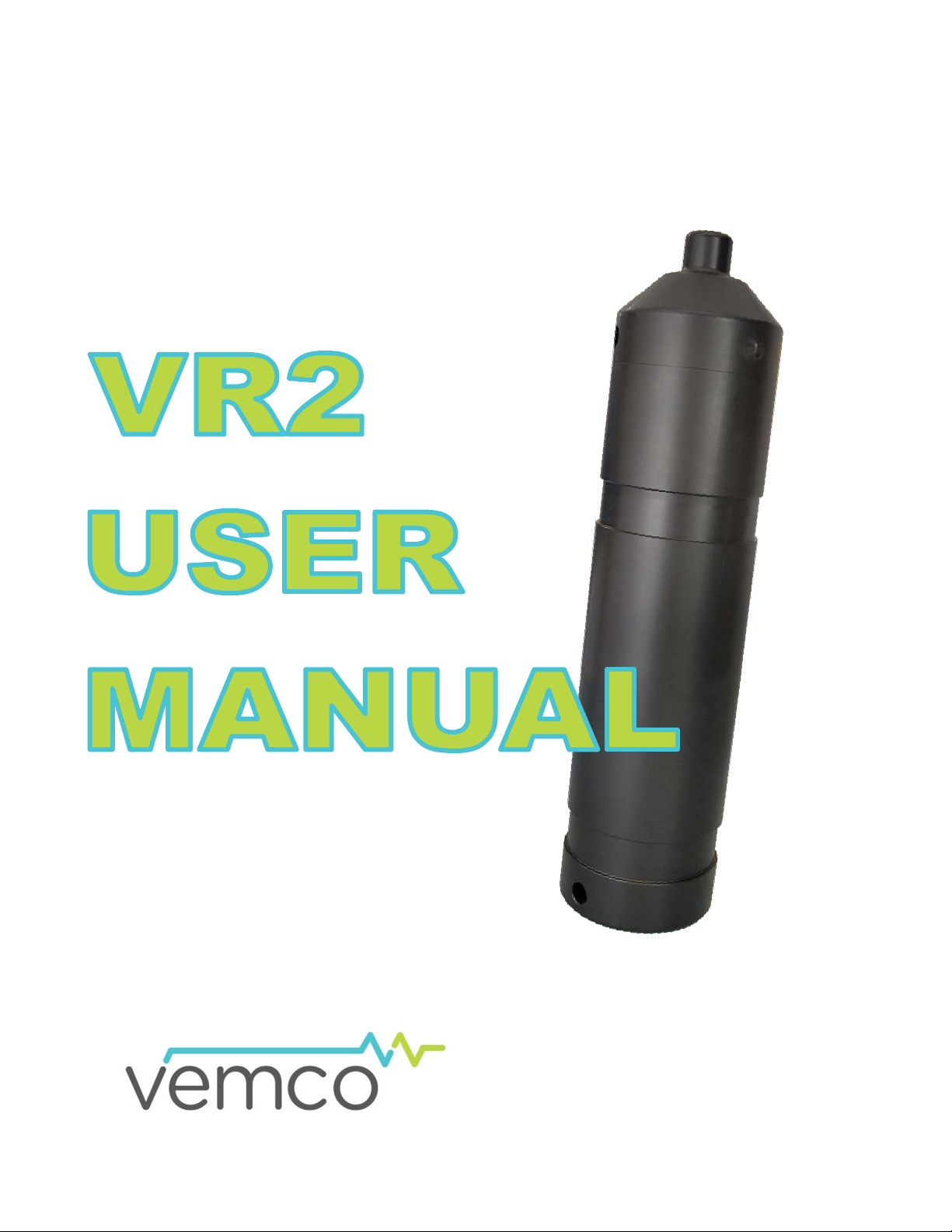
How to use the VR2
www.vemco.com
19 Sep 2013 DOC-4788-06
and with VUE software.
Page 2

Table of Contents
1 Introduction ........................................................................ 1
1.1 System Overview ................................................................................................................... 1
1.2 VR2 Case .............................................................................................................................. 2
1.2.1 Status Light (LED) ......................................................................................................... 3
1.2.2 Communication Probe Receptacle ................................................................................ 3
2 Getting Started .................................................................... 4
2.1 Testing ................................................................................................................................... 5
2.1.1 In-Air Test ...................................................................................................................... 5
2.1.2 In-Water Test ................................................................................................................ 6
3 Communication with VUE ....................................................... 7
3.1 Install VUE software .............................................................................................................. 7
3.2 Open database in VUE .......................................................................................................... 7
3.3 Connect to VR2 ..................................................................................................................... 8
3.4 Offload Data from VR2 Receiver ......................................................................................... 10
3.5 Initialize VR2 Receiver ......................................................................................................... 11
3.6 Change Code Map ............................................................................................................... 12
4 Deployment ....................................................................... 13
4.1 Deployment Facts/Tips ........................................................................................................ 13
4.1.1 Mooring ....................................................................................................................... 13
4.1.2 Spacing ....................................................................................................................... 13
4.1.3 Biofouling .................................................................................................................... 13
4.2 Mooring Line Attachment ..................................................................................................... 14
5 Maintenance ...................................................................... 16
5.1 Battery Replacement ........................................................................................................... 16
5.1.1 Open the VR2 Case .................................................................................................... 16
5.1.2 Remove Battery .......................................................................................................... 17
5.1.3 Insert Battery ............................................................................................................... 18
5.1.4 Close VR2 Case .......................................................................................................... 18
5.2 O-ring Care .......................................................................................................................... 19
5.2.1 Remove O-rings .......................................................................................................... 20
5.2.2 Clean O-ring Surfaces ................................................................................................. 20
5.3 O-ring Installation ................................................................................................................. 22
5.4 Storage ................................................................................................................................ 22
6 Additional Information .......................................................... 23
6.1 Flash Memory ...................................................................................................................... 23
6.2 Resume Study ..................................................................................................................... 23
6.3 Change VR PC Battery ........................................................................................................ 23
Page 3

7 Common Questions .............................................................. 24
© (2013) AMIRIX Systems Inc. All rights reserved. The information contained herein includes
their respective owners.
7.1 VUE related questions ......................................................................................................... 24
7.1.1 What is initialization? ................................................................................................... 24
7.1.2 Why does VUE create two .vrl file types? ................................................................... 24
7.1.3 What Date/Time format is my data stored in the receiver and displayed in VUE? ...... 24
7.1.4 How do I open the Options window? ........................................................................... 25
7.1.4.1 Display of location, units, and time .......................................................................... 25
7.1.4.2 Offload data settings ................................................................................................ 25
7.1.4.3 CSV file settings ...................................................................................................... 25
7.1.4.4 Other settings .......................................................................................................... 25
7.2 VR2 related questions ......................................................................................................... 26
7.2.1 How much detection range can I expect from my tags and receivers? ....................... 26
7.2.2 How long will my VR2 battery last? ............................................................................. 26
7.2.3 Does receiver orientation matter? ............................................................................... 26
7.2.4 At low tide my VR2 receiver will be exposed to direct sunlight, does this matter? ...... 26
8 Troubleshooting .................................................................. 27
8.1 VUE related troubleshooting ................................................................................................ 27
8.1.1 I cannot connect to my VR2 receiver .......................................................................... 27
8.1.2 These detected ID’s don’t belong to me ...................................................................... 27
8.2 VR2 case related troubleshooting ........................................................................................ 27
8.2.1 The threads have been damaged ............................................................................... 27
8.2.2 I think the case might be pressurized .......................................................................... 27
9 Appendix .......................................................................... 29
9.1 Cleaning Instructions ........................................................................................................... 29
9.2 Contact Information ............................................................................................................. 29
9.3 VR2 Specifications ............................................................................................................... 30
9.4 Warranty and Disclaimer ..................................................................................................... 31
9.5 Index .................................................................................................................................... 32
information which is confidential and proprietary to AMIRIX Systems Inc. and may not be used
or disclosed without prior written consent of AMIRIX Systems Inc.
The Bluetooth® word mark and logos are owned by the Bluetooth SIG, Inc. and any use of such
marks by AMIRIX Systems Inc. is under license. Other trademarks and trade names are those of
Page 4
static depth
Physical shocks to the receiver, such as bumping into a solid object, when it is
at any depth can result in a considerably higher pressure on the casing than
just the depth pressure and water may enter the VR2 case. If the O
their
receiver case. If you are suspicious that water has entered the receiver, then
follow the suggestions in
If the VR2 is not used in the manner specified by the
manufacturer protection may be impaired.
1 Introduction
1.1 System Overview
The VR2 is a submersible, acoustic receiver capable of identifying VEMCO coded transmitters. The receiver
operates on a factory set frequency and can decode various combinations of sensor and pingers. The VR2
receiver consists of electronics and hydrophone housed in a cylindrical corrosion resistant case. Its features
include a Smart LED (light emitting diode), two megabytes of data storage, a resume study feature, and a
replaceable battery (a single Lithium cell ) .
The VR2 records the pinger identification code number, date and time of each detection. This information is
stored in the receiver’s memory for later ret r ieval using a VR PC interface and a PC computer r unning VUE
software.
NOTE: As of January 2007, the VR2PC software has been replaced with the VEMCO User
Environment (VUE) software. VUE software is available at www.vemco.com/downloads/.
WARNING
The black VR2 pressure case and seal have a maximum
rating of 500 meters (730 psi).
-rings or
mating surfaces are dirty or damaged, then wat er may also enter the
section 8.2.2 for troubleshooting a pressurized case.
WARNING
VEMCO - VR2 Manual 1
Page 5
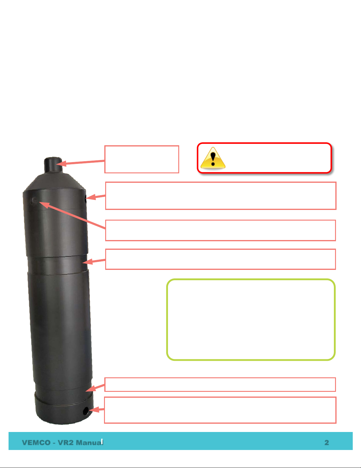
Cable Tie Groove: This is the second of the two grooves.
Hydrophone: the
Attachment Hole: This hole, which is almost 10 mm in diameter, is used with the
attachment details.
Cable Tie Groove: These grooves (there are two) are used to attach the VR2 to a
Probe Hole: Communication probe is inserted here. Hole i s stepped so the
Status Light (LED): The light flashes red to indicate the receiver’s status. Section
Do not bump the hydrophone or
unable to detect transmitters.
1.2 VR2 Case
The VR2 receiver is housed in the black plast ic high pressure case. The case consists of an out er cylinder that
is removed to install the D-cell Lithium battery, and the endcap which houses the hydrophone and connects to
the plastic internal casing. When the outer cylinder is removed, the internal casing protecting the electronics
can be seen.
A crucial part of the VR2 is the hydrophone, located at the top of the receiver. The hydr ophone is similar to a
microphone – it “listens” for sounds and transfers them to the electronics inside the receiver. Be very careful
not to bump the hydrophone or damage may occur that may prevent the receiver from detecting tags.
The VR2 case only needs to be opened when the battery must be installed or replaced.
receiver’s “microphone”
and most delicate part.
Communication Probe can only be inser ted from only one direction. Section 1.2.2
has more information on the Communication P robe.
1.2.1 has the full description.
line – see section 4.2.
the receiver may be damaged and
Status Light (LED) Meanings:
No flashes = not initialized or no power
2 quick flashes every 5 sec = Recording Mode
2 quick flashes every 10 sec = Memory Full
1 quick flash = acoustic ping received
1 bright, long flash = detection writt en to memory
Cable Tie Grooves to secure the VR2 while it is dep l oyed. Section 4.2 has more
VEMCO - VR2 Manual 2
Page 6
Status Light Flash (LED) meanings
Receiver is not initialized or the battery is
disconnected/depleted
Two quick flashes every 10
seconds
1.2.1 Status Light (LED)
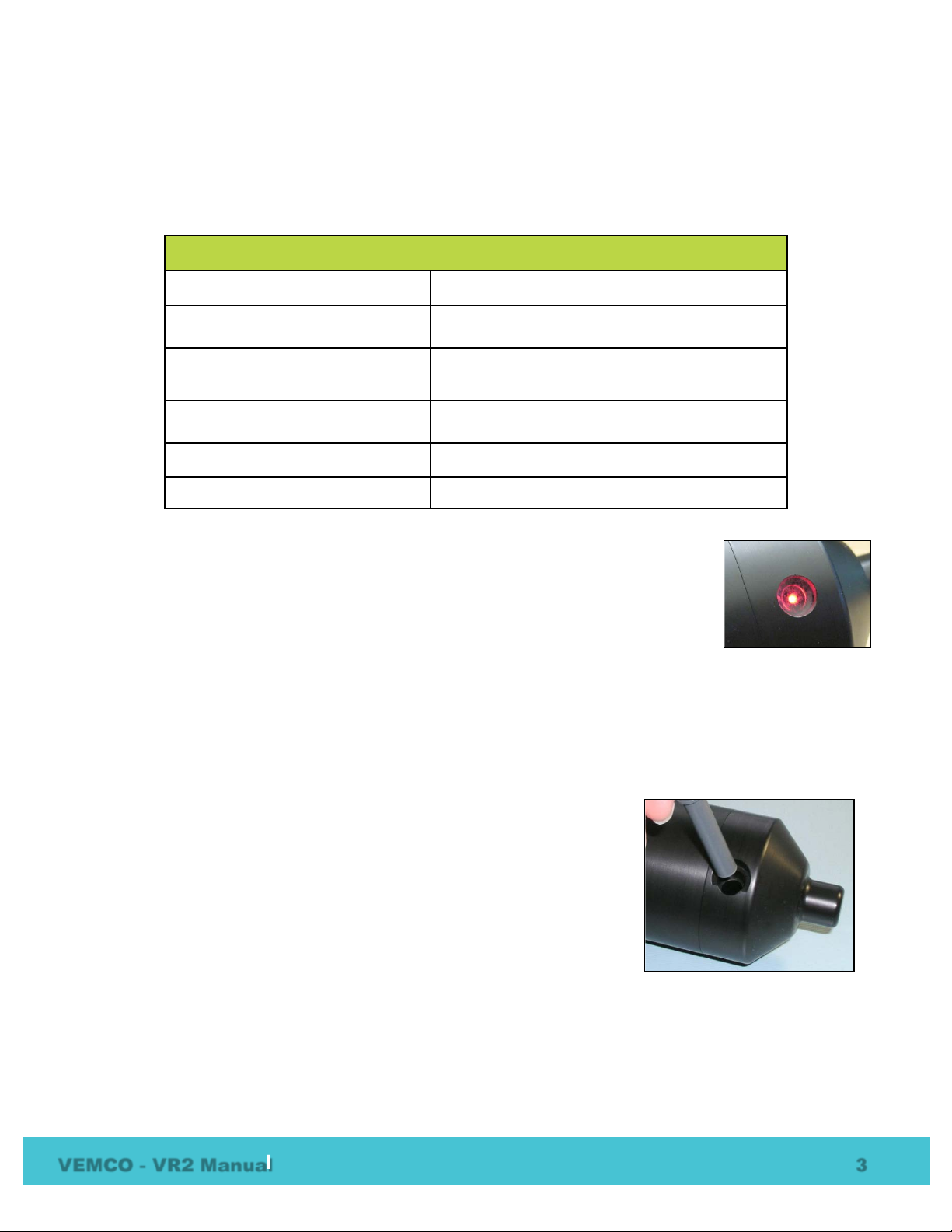
The red Status Light on the side of the VR2 case flashes based on the task being performed or the status of the
receiver. The flashes can be interpreted using the table below. The Status Light is an LED (Light Emitting
Diode) and has been referred to as such in past documentation.
VR2 LED Flashes Interpretation of Flashes
No flash
Two quick flashes every 5 seconds
One short flash An acoustic ping was received
One long flash A complete detection was written to memory
VR2 is in record mode (records any received
pings)
The VR2 memory full
When the VR2 is powered (see the Battery section), the Smart LED will emit three
quick flashes. After ten seconds, two long flashes will indicate that necessary
information was read from memory and the receiver is ready for initialization. The LED
will not flash again until the receiver has been in itialized. When the receiver has been
initialized (record mode), the LED emits two quick flashes every five seconds. A
received acoustic ping will be indicated with a short dim flash from the LED. A long
bright flash following a sequence (6-7) of short flashes indicates that a transmitter ID
code has been received and stored to memory. Two flashes every ten seconds from an initial ized receiver
indicates that the memory is full.
1.2.2 Communication Probe Receptacle
The VR2 receiver has a receptacle for the communication probe from the VR
PC computer interface. The receptacle, called the probe hole, is located on
the end-cap and is identified in the first photo on the previous page. The
probe hole is stepped to ensure that the communication probe is inserted
from only one direction. Remove any marine growth from the receptacle
before inserting the probe. Ensure that the probe is inserted until the O-ring
on the probe is fully seated.
VEMCO - VR2 Manual 3
Page 7

2 Getting Started
The list below is designed for users who are familiar with VEMCO equipment. Please read the manual
completely before using the VR2 receiver.
1. Install VUE software on a computer (see section 3.1).
2. Setup sensor transmitter information in VUE software (see VUE softwar e manual). This does not
have to be performed before deployment.
3. Open VR2 case (see section 5.1.1).
4. Install battery in VR2 receiver (see section 5.1.3).
5. Inspect and clean O-rings (section 5.2).
6. Close the VR2 case (section 5.1.4).
7. Perform an air test (see section 2.1.1).
8. *Initialize VR2 to begin recording study (see section 3.5). This will also erase the data recorded
during the air test.
9. Remove communication probe from VR2 receiver.
10. Deploy VR2 receiver (see section 4).
11. Retrieve VR2 receiver.
12. Establish commu nication between VR2 and VUE (see section 3.3).
13. *Offload data f r om VR2 receiver (see section 3.4).
14. Remove communication probe from VR2 receiver.
15. If study is continuing, re-deploy VR2. If study is not continuing, remove battery to stop recording
(see section 5.1.2).
*CAUTION: Ensure that your PC clock time is accurate! The VR2 has an internal clock that will be
synchronized with the PC clock. At the time of Initialization or Study Start, the VR2 records the PC
clock time in its memory. When the study is finished and data is downloaded, the VUE software
records the VR2 start and end times alon g with the PC clock time in the VUE database. Users should
be aware that the VR2 end time will most likely be different from the PC clock time. If users wish to
time- correct transmitter detection times, then they must ensure that the PC clock time is accurate at
Initialization and Study End. If more than one computer is used to initialize the receivers and load
data, then make sure the PC clock time is accurate on all computers.
VEMCO - VR2 Manual 4
Page 8
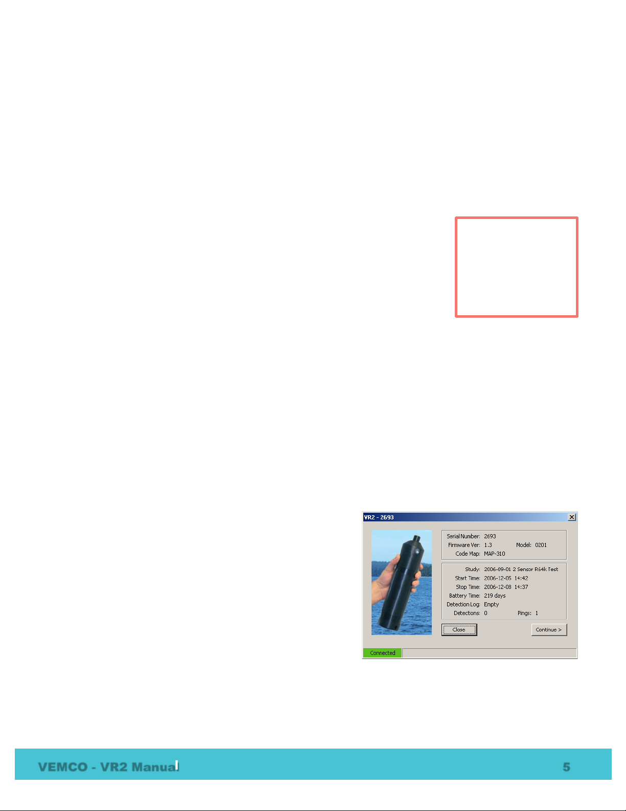
Receiver Control Window
2.1 Testing
Before deploying a VR2 receiver, we advise you conduct a test with a tag to verify that the VR2 is operating
properly. This test also creates a VRL file ( detection data file) containing all the configuration information
for this receiver – handy to keep as a record of the receiver’s configuration.
Tests should be performed in both air and water.
2.1.1 In-Air Test
The VR2 can detect coded pingers in air, but at a much reduced range (up to three
meters) compared to testing in water. Perform air tests away from electrical noise
sources such as motors, PC screens, or fluorescent lights. Before beginning th e test,
ensure the clock of the PC to be used is set to the correct time. Follow the steps
listed:
For VR2 receivers with firmware versions 1.01 or lower:
1. Open VUE software on your computer.
2. Insert the VR PC interface probe into the VR2.
3. Initialize a study and remove the prob e.
4. Activate a coded pinger transmitting o n the same frequency that the VR2 is set to receive (typically 69
kHz; refer to Transmitter Specifications manual for the pinger information). A VR100 receiver may be
used to audibly confirm when the pinger is transmitting.
5. Lay the VR2 receiver on its side with the transducer (pointed end) past the edge of a table.
6. Position the pinger up to 1 meter from the transducer.
7. Watch the LED on the VR2 receiver. The LED wil l flash briefly for each acoustic ping received. A long
bright flash occurs when the receiver has successfully recorded the ID.
8. After a few transmissions have been recorded, connect the VR2 to the VR PC interface and download the
data.
For VR2 receivers with firmware versions 1.02 or higher:
1. Open VUE software on your PC.
2. Insert the VR PC probe into the Probe Hole in the VR2.
3. When the receiver appears in the selectio n tree on the left
side of the window, double-click the receiver name to open
the Receiver Control Window.
4. Activate a coded pinger transmitting o n the same frequency
that the VR2 is set to receive (typically 69 kHz; refer to
Transmitter Specifications manual for the pinger
information). A VR100 receiver may be used to audibly
confirm when the pinger is transmitting.
5. Lay the VR2 receiver on its side with the transducer
(pointed end) past the edge of a table.
6. Position the pinger up to 1 meter from the transducer. Watch the LED on the VR2 receiver. The LED
will flash briefly for each acoustic pulse received. A long bright flash occurs when the receiver has
successfully recorded the ID memory.
Perform air tests
away from electrical
noise sources such
as motors, PC
screens, or
fluorescent lights.
VEMCO - VR2 Manual 5
Page 9

7. Watch the LED on the VR2 receiver. The LED wil l flash briefly for each acoustic ping r eceived. A long
flash occurs when the receiver is writing information to the memory.
8. Verify that the “Detections” and “Pings” numbers in the Receiver Control Window are increasin g.
Stop recording and retrieve the stored data (see the VUE manual for details).
2.1.2 In-Water Test
Tests performed in water are almost iden tical to the in-air test explained above. The only difference is that
the tags should be positioned farther from the receivers – 5 meters is suggested. In-water tests are often
performed to establish an ideal range for the VR2 receivers in the environment in which they are moored.
1. Initialize a study with your watch synchronized to the PC time.
2. Perform a Range Test. Details pertaining to Range Testing are found at www.vemco.com/customer-
service/?cs-tutorials.
VEMCO - VR2 Manual 6
Page 10
3 Communication with VUE
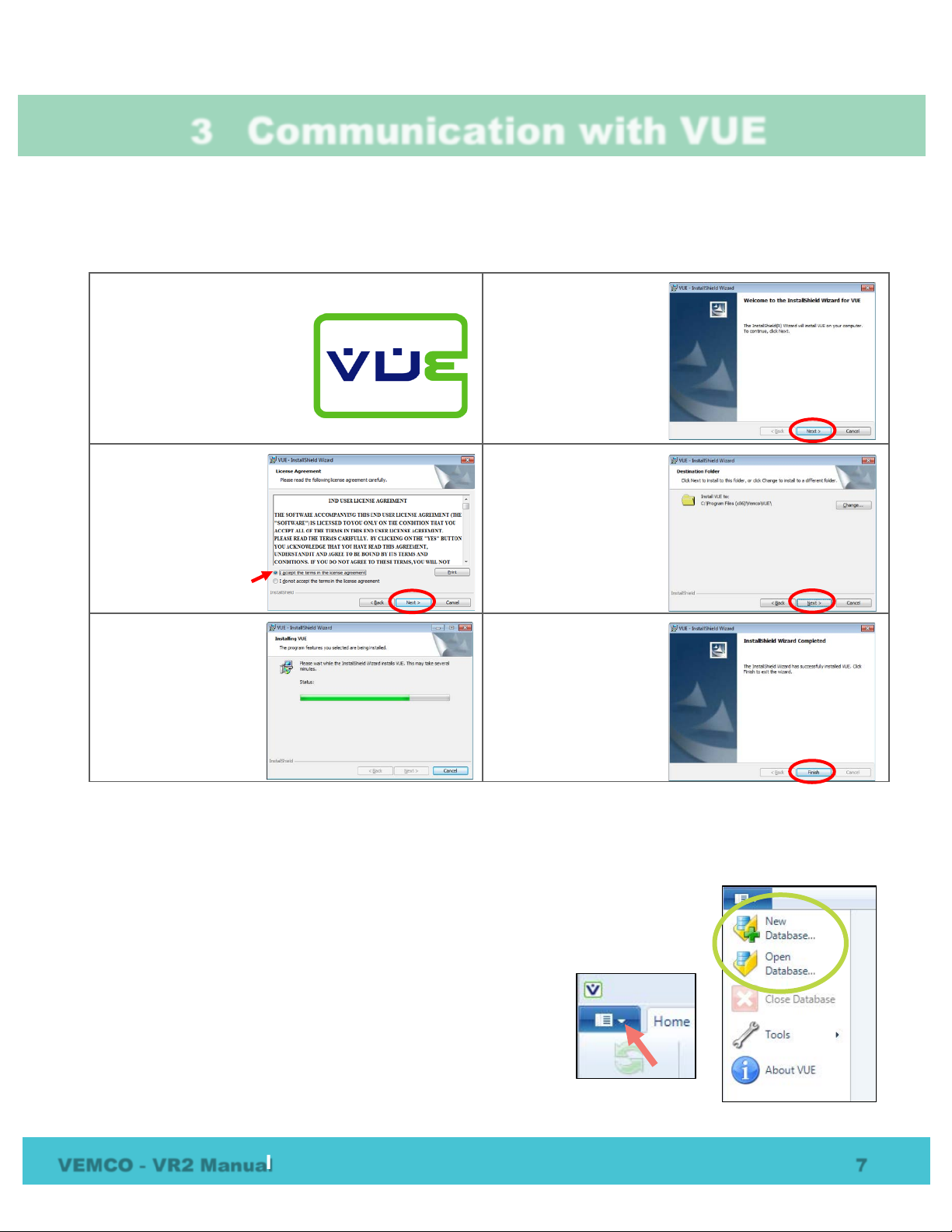
3.1 Install VUE software
The VUE software requires Windows XP SP2 , Windows VISTA, Windows 7, or Windows 8.
STEP 1
Run the latest “Install_VUE”
application file. The latest file
is always available from our
website, www.vemco.com.
STEP 3
Read the license
agreement and select
“I accept” and “Next” if
you agree to the terms.
STEP 5
Wait while the VUE
software is installed.
Click “Next” when it
becomes enabled.
STEP 2
Click “Next” when the
Install Shield Wizard
begins.
STEP 4
Click “Next” to install
VUE in the folder
shown, or click
“Change” to select a
difference folder.
STEP 6
Click “Finished” to exit
the setup wizard.
3.2 Open database in VUE
To create a new database in VUE or to open an existing database, select the VUE menu
button in the top left corner of the VUE software (see arrow below). Choose either
“New Database” or “Open Database” from the menu that appears (circled at right).
If you are opening a database created by an earlier version of VUE
(version 1.4.4 or older), you will receive a warning that the
database will be converted to the new ver sion of VUE and will no
longer be compatible with older versions of the software.
VEMCO - VR2 Manual 7
Page 11
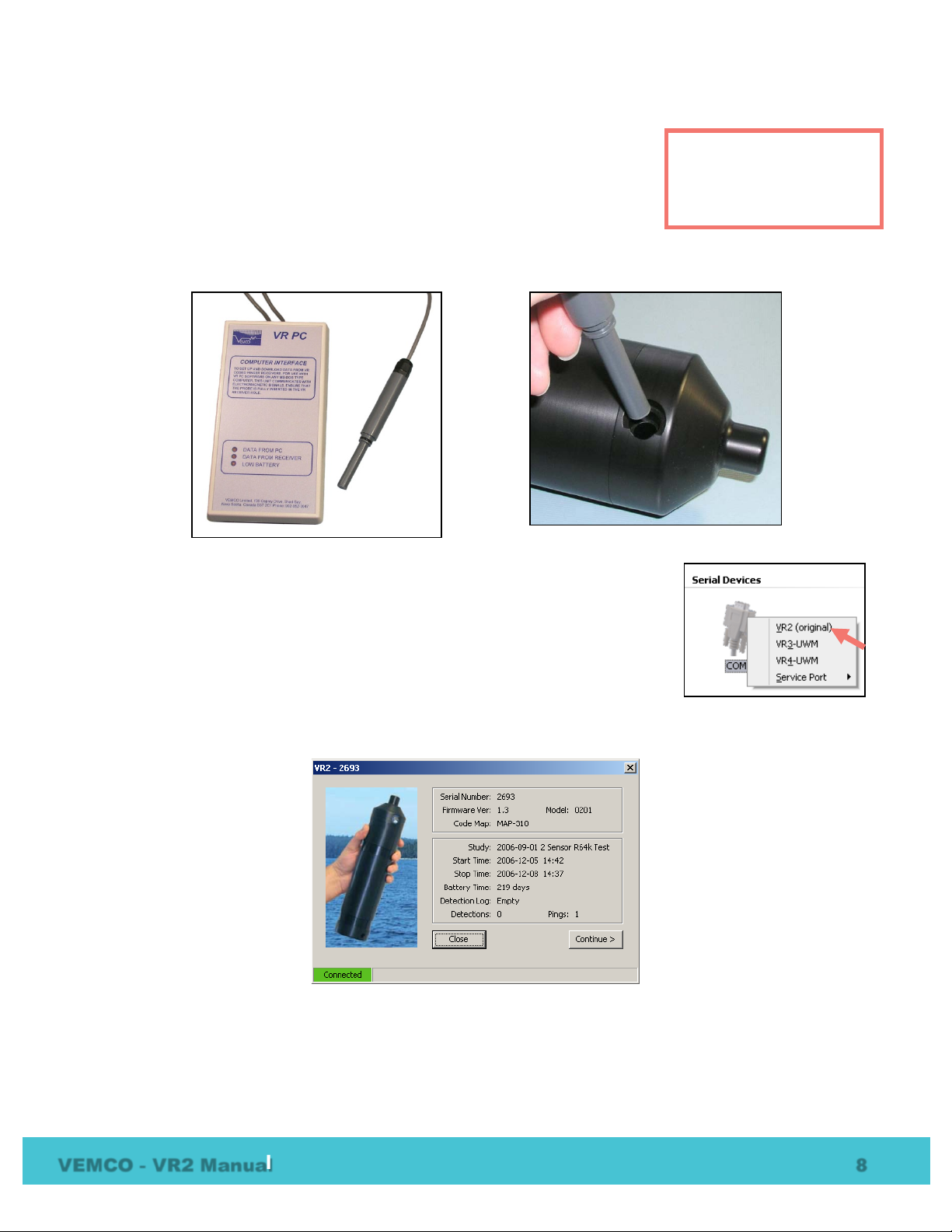
VR PC Interface with probe
Inserting probe in VR2
3.3 Connect to VR2
Open the VUE software and open a database. The software can be setup to
automatically open the last database used with the software on this computer
(see section 7.1.4).
Connect the VRPC Interface box to the serial port on the computer and make note of the serial port number.
Insert the VR PC Interface probe into the large hole in the VR2 as shown in the photo on the right below.
Open the Home tab in the VUE software and sel ect the correct COM (serial) port
number in the Serial Devices section of the window (see picture at right). A list of
receiver types will appear; select VR2 (original) from the list and wait for
communication to be established. The red status lights on the VRPC interface box
verify that communication is being established.
The Receiver Controller Window (RCW) will open and, after communicating with the VR2, list the status of
the receiver.
Continue to the next window (shown below) to verify that the PC time is correct. If the time shown in the
window is not correct, use the “Set Clock” button and change the time, date, and time zone so they are
correctly set to your local time.
A database must be open
for VUE to communicate
with a VR2.
VEMCO - VR2 Manual 8
Page 12
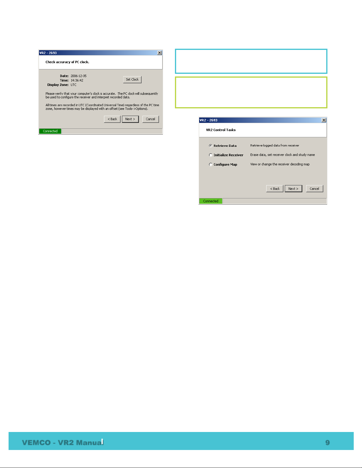
NOTE: The PC clock must be set to the correct
NOTE: “Set Clock” updates the PC clock, not the
local date, time, and time zone!
receiver clock. The receiver time will be changed to
the PC time when you initialize the receiver.
After ensuring the PC clock has been set cor r ectly
(including time zone), continue to the next window for a
selection of VR2 Control tasks (shown at ri ght). See
sections 3.4 to 3.6 for details on each task.
VEMCO - VR2 Manual 9
Page 13
NOTE: The UTC offset should only be used if
Verify the receiver you are communicating with is
the intended unit,
erasing receiver memory files, or data coul d be l ost.
The receiver name is displayed in the RCW.
3.4 Offload Data from VR2 Receiver
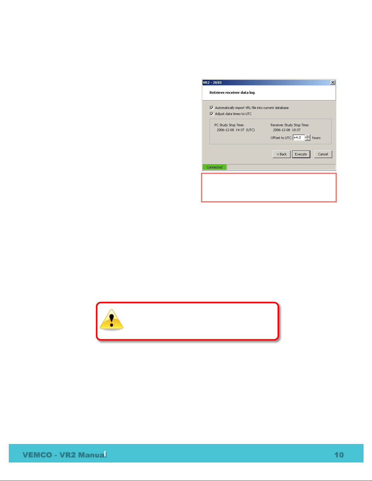
Select the radio button next to “Retrieve Data” in the VR2 Control Tasks list and then select “Next” to open
the “Retrieve receiver data” window ( shown at right).
“Automatically importing the VRL file into current
database” allows the data to be viewed immediately after
the data are recovered. For large data files, you may
choose to unselect this and import the data later. This will
speed up the offload process.
This option is provided to adjust the times to UTC. This is
only necessary if the receiver was initialized using the
VR2PC software. If the VR2 was initialized usin g the
VUE software, the times are already UTC and an
adjustment is not necessary.
To adjust the times to UTC, first click the “Adjust data
times to UTC” box. Select the correct offset based on the
difference between UTC and the receiver’s time. A
suggested offset is shown based on the PC clock and the
receiver’s clock. The PC UTC time is shown on the left and the receiver’s time is shown on the right. Set the
value in the “Offset to UTC” box to the hours that must be added or subtracted from the receiver’s time to
obtain the correct UTC time.
After the desired retrieval settings are made, the “Execute” button will begin t he process.
The data are stored in a VRL file which can b e imported later into this or another VUE database by using the
Import File feature explained in the VUE software manual.
VUE software allows you to communicate with up to seven receivers simultaneously. Since your PC can talk
to as many VR2 units as are connected to the PC, it is important that you ensure you are communicating with
the correct unit, particularly before initializing and erasing receiver memory files.
particularly before initializing and
data are being retrieved from a VR2 that was
initialized with the VR2PC software.
VEMCO - VR2 Manual 10
Page 14
It is vital that the PC clock be
correctly set to your local
time, including time zone,
before the VR2 is initialized.
Initializing the VR2 will erase
the receiver’s memory.
Retrieve all detection logs
before the VR2 is initialized.
3.5 Initialize VR2 Receiver
Initializing a receiver clears the receiver logs, sets the receiver clock,
and stores configuration information into the receiver memory.
Initialization is required to put the VR2 receiver into record mode.
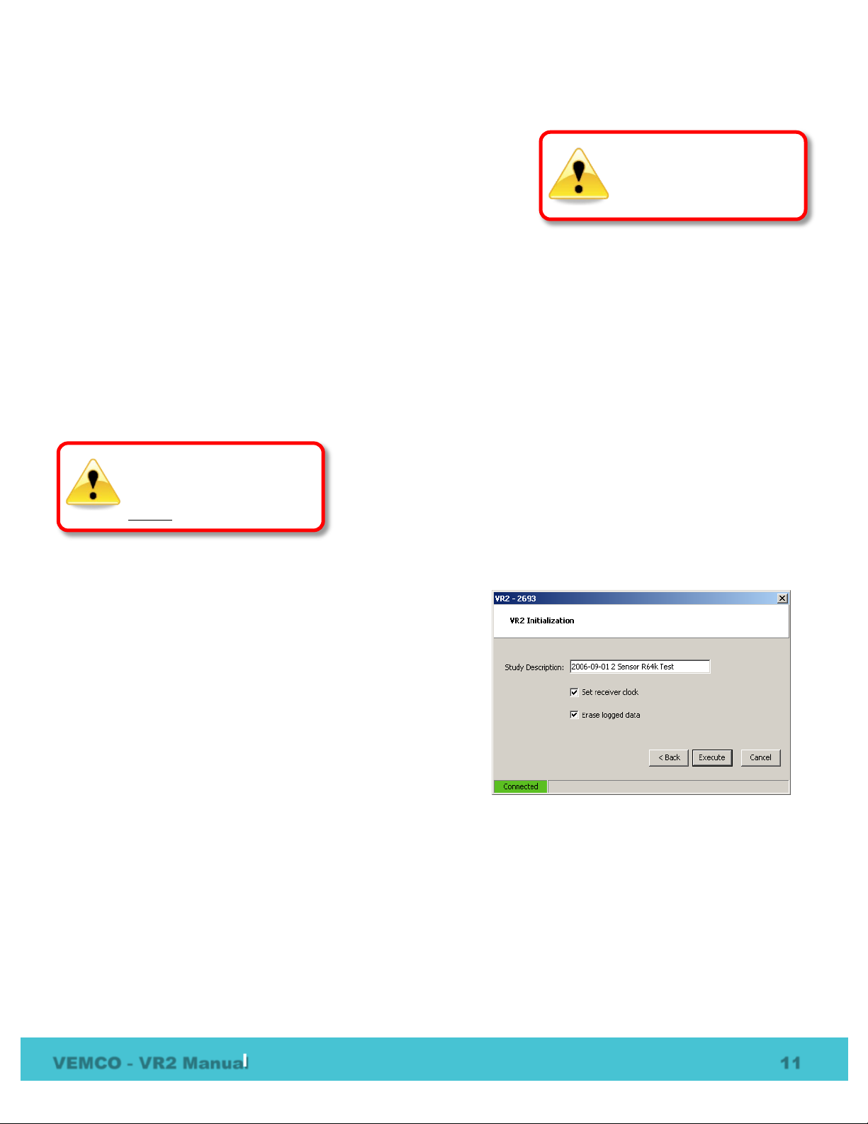
Select the radio button next to “Initialize Receiver” in the VR2 Control Tasks list and then select “Next” to
open the “VR2 Initialization” window (shown below).
The VR2 does not support the use of a separate Station (Location) Name stored into memory, however the
“Study Description Field “ can be used to include both a receiver name and location details.
A brief description or name of the study can be saved in the receiver’s memory and associated with the data.
This could be the location where the VR2 was deployed or the name of the study being conducted.
The receiver clock is to the PC clock and is used to time stamp the detections as they are stored in memory.
This is why it is vital that the PC clock be correct, including time zone, before the VR2 is initialized.
The initialization process clears the memory from the receiver,
NOTE: You will not be able to proceed un less Set Receiver Clock and Erase logged Data are both selected.
After the desired study description has been entered and Set
Receiver Clock and Erase logged Data are both selected,
click the “Execute” button to begin the initialization process.
Once you have initialized a receiver and are ready for
deployment, it is wise to test with a transmitter and then to
offload (retrieve) the data. This will create a VRL file which
contains all the configuration information for this receiver.
This file can be read later if required to verify that the VR2
initialized properly before deployment.
erasing all detections that are stored in memory. If there are data in
the VR2 that have not been retrieved, they must be retrieved before
the receiver is initialized.
VEMCO - VR2 Manual 11
Page 15
WARNING
detection data.
WARNING
erases data.
3.6 Change Code Map
A Code Map is programmed into every VR2 receiver. The Code map instructs the VR2 to decode a particular pattern of
tag transmissions.
detect and decode VEMCO transmitters.
The Code Map should be changed with caution. Configuring a receiver with an incorrect map may r esult in
lost detection data. To determine which VEMCO code map to use, visit www.vemco.com or consult your
VEMCO sales agent.
Configuring a receiver with a new map automatically erases the data log from the VR2. Please offload all
data before configuring with a code map.
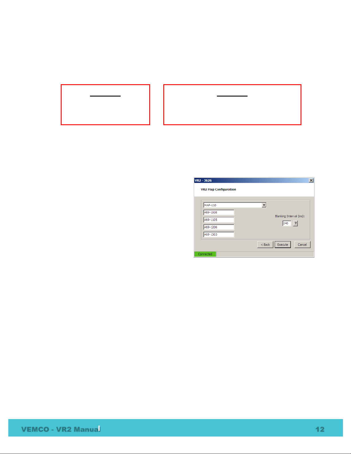
Select the radio button next to “Configure Map” in the VR2
Control Tasks list and then select “Next” to open the “VR2
Map Configuration” window (shown at right).
The “VR2 Map Configuration” window will automatically
display the current map used within the VR2.
VEMCO maps are listed in the top drop-down box.
Selecting one of these maps will automatically set the
corresponding tag types in the boxes below. Blanking
Interval is typically 240 milliseconds. Do not change this
value unless instructed by VEMCO Support.
The “Execute” button will start the configuration process to store the new map settings in the VR2.
The VR2 Map Configuration window is used to change the Code Map used by the VR2 to
Configuring a receiver with an
incorrect map may result in lost
Offload all data before configuring with a code
map. Configuring a receiver with a new map
VEMCO - VR2 Manual 12
Page 16
Never cover the Status Light (LED)/Release Valve.
The release valve
and must not be blocked by tape or paint.
4 Deployment
How a VR2 is deployed is driven by the environment it is being deployed in and the type of study being
performed. Some important points to keep in mind when designing a deployment plan for your VR2
receivers are explained here. The common method for attaching a VR2 to a mooring line is also given.
4.1 Deployment Facts/Tips
4.1.1 Mooring
VR2 receivers are moored in many configurations often reflecting the bathymetry and oceanographic/weather
conditions. A simple mooring design generally works well. However, in rougher conditions, heavier weights
and mooring lines are usually required. If a bottom mooring is desired, the VR2 should be positioned above
the floor such that it has an unobstructed “view” of tagged animals within their expected acoustic range.
Ensure the VR2’s hydrophone is unblocked (e.g. do not position an air filled buoy directly above the
hydrophone) and free of any significant biofouling. In high flow locations, you might conside r us ing hydr o
dynamically shaped buoys and low profile anchors.
For the best horizontal range, mount the VR2 r eceiver in a
vertical position. If the VR2 is deployed close to the bottom,
mount the VR2 with the hydrophone pointing up to the
surface. If the VR2 is deployed close to the surface in deep
water, you could position the VR2 so the hydrophone is
pointing down. Conduct range testing to determine the
optimum orientation.
4.1.2 Spacing
CAUTION: The hydrophone must
be kept free of mooring lines
and obstructions. Objects
around the hydrophone will
adversely affect the detection
range of the VR2 receiver.
Receiver spacing is generally determined based on range testing and historical ac oustic data. Our position is
that you should try to space receivers such that you achieve good detection probability in most or all weather
conditions. It is not always necessary to have 100% coverage if you have several other locations where you
know the animals will be passing through. However, if you wish to accurately quantify the passing of
animals through receiver locations then you should strive for 100% detection
probability. Typical spacing is usually between 100 and 1,000 meters.
4.1.3 Biofouling
Some customers use a rubber shrink tape, such as DAFLEX ST250 Cold Shrink Tape, available from Digikey
(W211-ND), to prevent biofouling on the VR2 receiver. It can be used to cover the entire receiver case or
just the Probe Hole and does not leave a glue residue when it’s remo ved. Another option is to use an
antifouling paint, such as Interlux Micron CSC.
VEMCO - VR2 Manual 13
See the Gate Design
tutorial at www.vemco.com
must be able to pop open if needed
Page 17
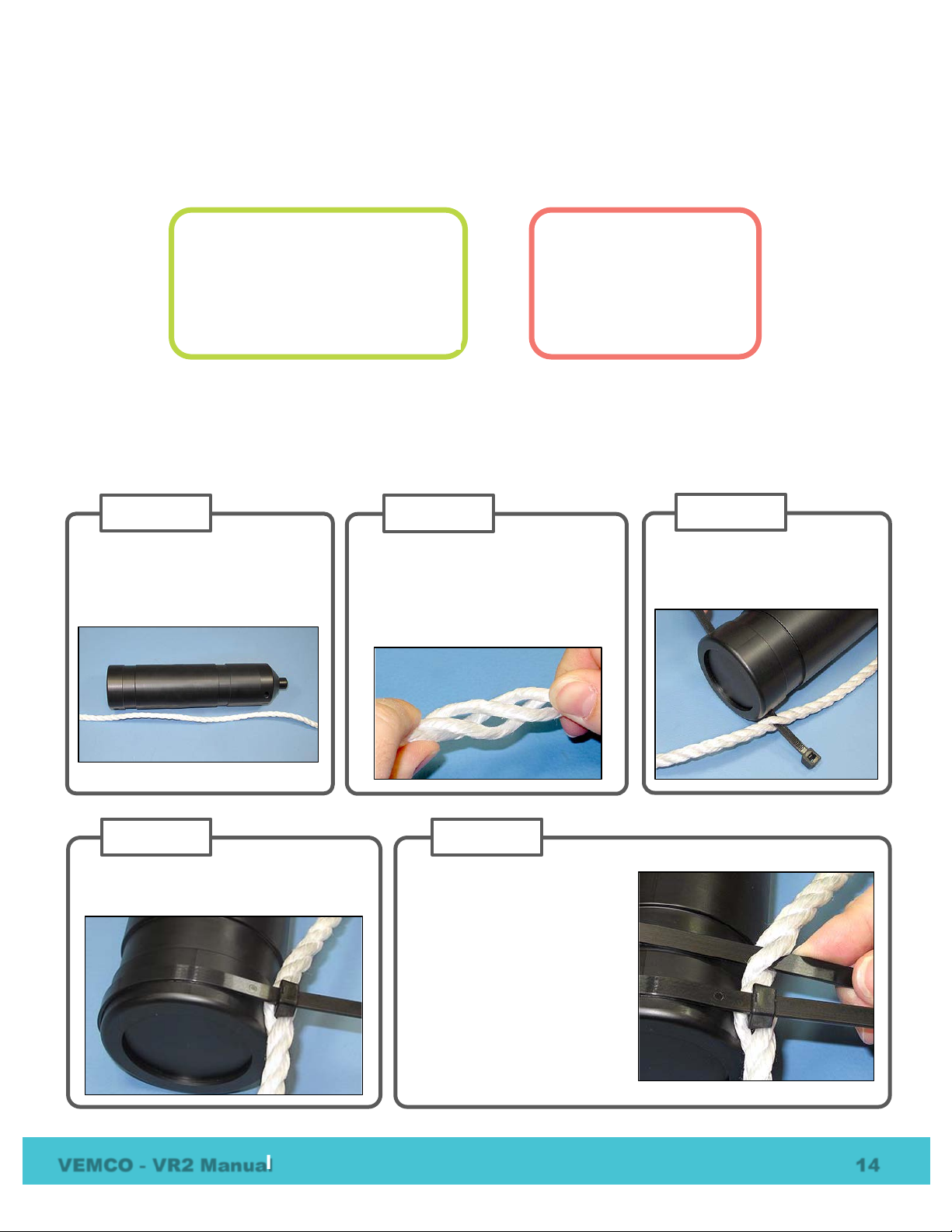
Twist the rope so the strands of the
rope separate from each other and
an opening in the rope is seen.
This is referred to as opening the
“warp in the rope”.
STEP 2
L
head of the cable tie is next to the rope.
STEP 4
Open the warp in the rope
again and slide another
cable tie through
lines up with the bottom half
of the lower groove
the body of the VR2
Tighten the cable tie so the
tie’s head is next to the
rope.
STEP 5
Non-reusable lashing cable ties
120 lb tensile strength
Identify the location on the rope
where the bottom of the VR2
receiver will be attached.
STEP 1
Slide one of the cable ties
through the center of the rope
and the Attachment Hole
STEP 3
4.2 Mooring Line Attachment
The common method used to attach a VR2 receiver to a mooring line is to use five cable ti es (zip tie or tiewrap) with the following characteristics:
A set of five cable ties is shipped with each new VR2 receiver and more may be purchased fro m VE MCO
(product number HWE 507450).
Follow the instructions listed below t o attach the VR2 receiver to the rope used as the mooring line. A
minimum rope size of 3/8" diameter nylon rope is suggested.
atch and tighten the cable tie so the
VEMCO - VR2 Manual 14
• 388 mm (15.25") lon g
• 7.5 mm (0.3") wide
• UV protected
•
Suggested minimum:
3/8" diameter
nylon rope
.
rope so it
around
.
Page 18
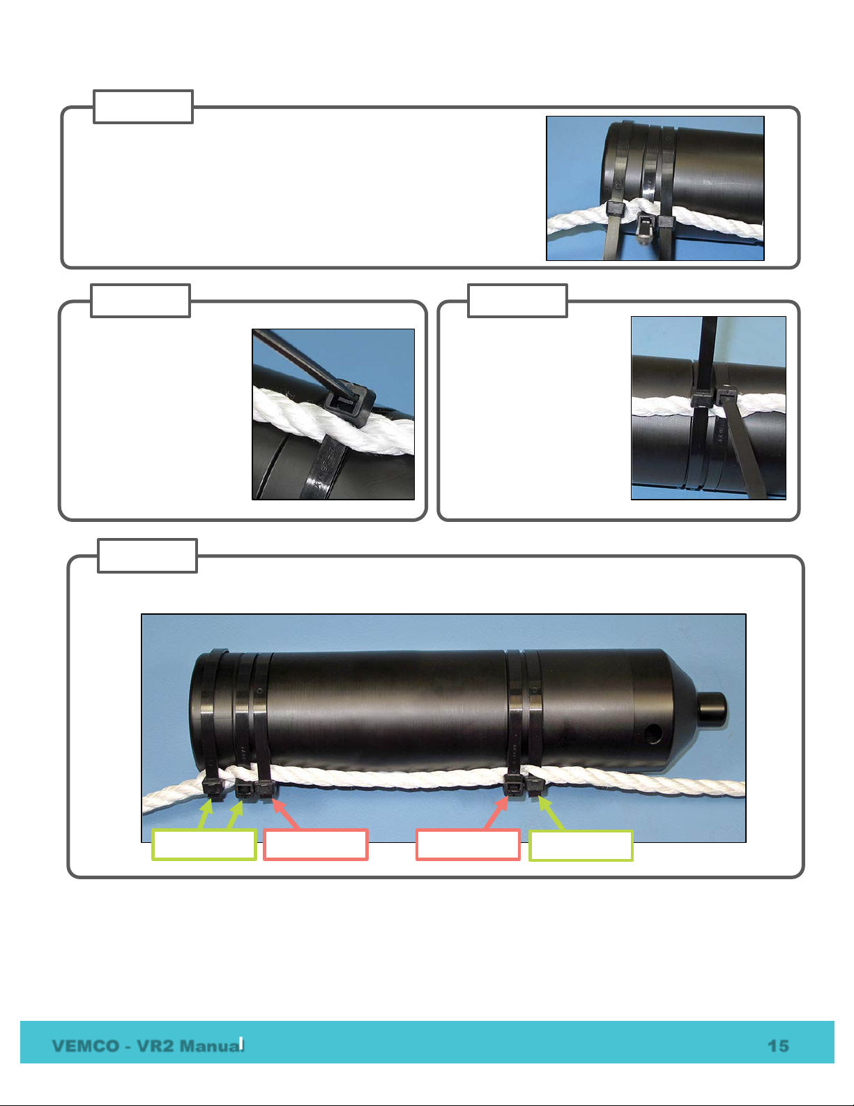
Wrap a third cable tie around the VR2 receiver and the rope so the
cable tie occupies the top half of the lower groove in the VR2 body.
The bottom half of the groove is already occupied by t he cable tie
from Step 5
Latch the cable tie
STEP 6
Wrap a
around the VR2 receiver
and the rope so the cable
tie occupies the
half of the groove
Step 7
tie so the head of the
cable tie is
STEP 8
Open the warp in the rope
next to the groove closest
to the hydrophone and
slide another cable tie
through rope so it lines up
with the
groove.
Tighten the cable tie so
the tie’s head is next to
the rope.
STEP 7
Trim the cable ties so there is no excess cable tie material and no sharp edges.
STEP 9
Through Rope
Around Rope
Through Rope
Around Rope
so the head of the cable tie is over the rope.
fifth cable tie
top half of that
. Latch the cable
IMPORTANT: Cut the cable ties when removing a VR2 from the mooring line. DO NOT re-use
VEMCO - VR2 Manual 15
cable ties. Use only new cable ties when deploying a VR2 receiver.
bottom
used in
over the rope.
Page 19
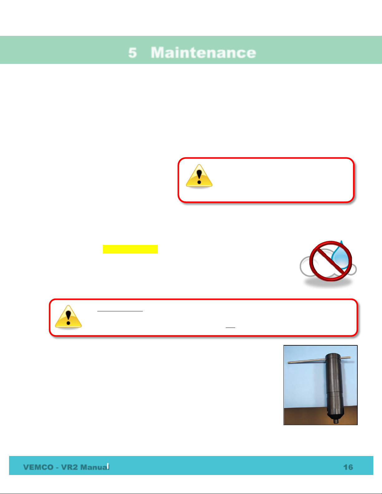
It is vitally important that the electronics insi de the receiver case do not come in contact
The internal casing surrounding the
enter the case and damage the electronics.
5 Maintenance
5.1 Battery Replacement
The VR2 receiver is housed in a black plastic high pressure case with an outer cylinder that is removed from
the receiver, revealing the internal casing protecting the electronics and allowing access to the D-cell Lithium
battery. The metal/PVC internal casing has an O-ring between the metal internal casing and the PVC battery
cup. This O-ring reduces vibration. It is not used for water protectio n. Do not grease this O-ring.
Replacing a battery in this VR2 requires four steps:
1. Opening the case (section 5.1.1)
2. Removing the battery (section 5.1.2)
3. Inserting the battery (section 5.1.3)
4. Closing the case (section 5.1.4)
5.1.1 Open the VR2 Case
electronics is not waterproof. Water, even
condensation from a humid environment, wi l l
Two steel rods are necessary to properly open and close the VR2 case. Every shipment of new VR2 receivers
includes a pair of steel rods.
1. Make sure there is absolutely no water on or near the VR2 case. Water, even in a small
quantity, can damage the VR2 internal circuits beyond repair. If the VR2 is attached to
a wet rope, remove the receiver from the rope before opening the case.
This also means that the electronics cannot b e exposed to a sudden change in
temperature and humidity which may cause condensation to develop on the
electronics.
with any water or the receiver will be damaged. For this reason, VEMCO recommends the
VR2 be opened in a controlled environment and not in the field or on the deck of a boat.
2. Place the VR2 on a clean, flat surface so the hydrophone (tapered end) is hanging
over the edge enough that the large hole is past the edge of the surface. DO NOT
let the receiver fall off the surface. TIP: A non-slip surface, such as a rubber mat,
helps keep the VR2 in place while opening it.
3. Insert one steel rod into the hole that runs through the diameter of the case near
the flat end of the VR2. Position it so most of the rod is on the left side of the
receiver as shown.
4. Place a hand on the back of the receiver to hold it in place. The back of the
receiver often “jumps” during Step 6 so be pre pared.
VEMCO - VR2 Manual 16
Page 20
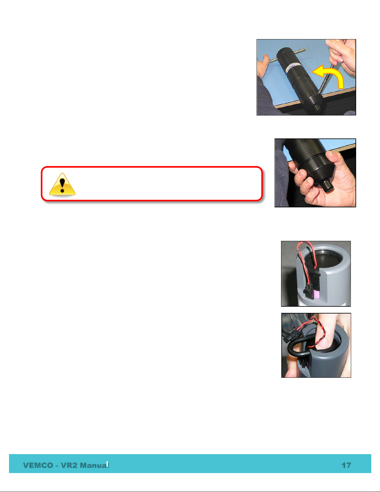
DO NOT impact the threads on the end-cap or they will dent
5. Insert the other steel rod into the hole in the Probe Hole on the end-cap
of the receiver and hold on to the rod – it will slide right through the hole
and potentially damage something below. Make sure the rod is fully
inserted into the hole or damage may occur to the Probe Hole.
6. Apply pressure to the rod in the Probe Hole to turn it in a counter-
clockwise direction when you are facing the hydrophone. The rod at the
back of the receiver acts as a brace while you apply pressure, but be
careful of it “jumping” off the flat surface.
7. Unscrew the hydrophone end from the main body.
8. Remove the steel rods from the VR2 case and set them aside.
9. Slide the end-cap and cylinder apart until the battery compartment has cleared
the cylinder. Be very careful not to damage the threads on the end-cap or the
VR2 won’t close and seal properly.
and prevent the VR2 case from closing. See section 8.2.1
for tips on thread care.
5.1.2 Remove Battery
1. Press the release lever on the battery connector and pull the connector apart. A
small and a small flat screw driver may help release the lever.
2. Press the back of the battery towards the body of the VR2 until the battery is not
pressing against the O-ring. There is a spring at the other end of the battery cup
so the battery will move.
3. Slip the O-ring from its groove as shown in the photo. The O-ring’s purpose is to
hold the battery from sliding out the end of the battery cup.
4. Slide the O-ring along the battery’s connector wires so they are separated from
each other.
5. Remove the battery.
VEMCO - VR2 Manual 17
Page 21
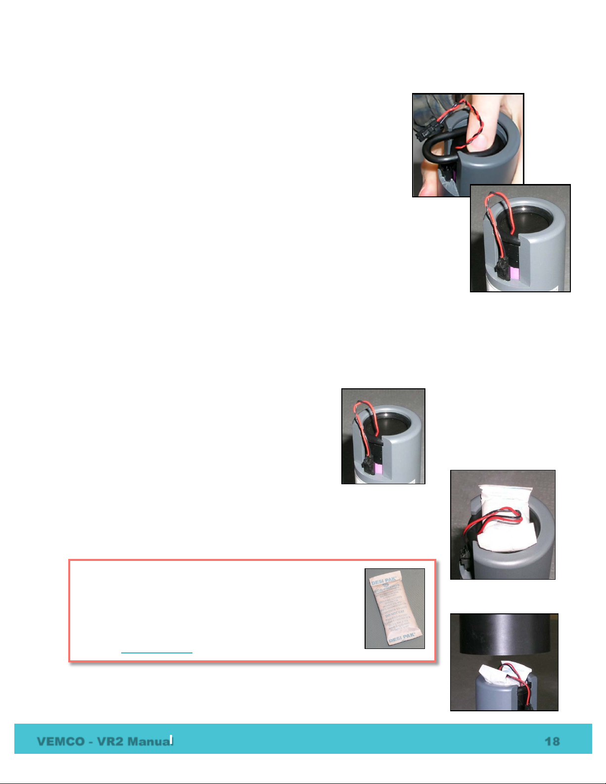
A desiccant pack has been included in the bottom of the VR2 to
reduce the occurrence of condensation
should remain in the receiver case during storage and deployment.
We recommend that you replace the desiccant pack with each
deployment and with each battery replacement cycle.
More information on the availability and usage of the
located
5.1.3 Insert Battery
1. Remove the O-ring from the groove in the battery cup if it hasn’t already
been removed.
2. Slide the wire-free end of the new battery into the battery cu p. The
connector wires should stick out the battery cup.
3. Thread the connector wires through the O-ring.
4. Press on the battery until the end of the battery is below the O-ring
groove.
5. Squeeze the O-ring into an oval shape and push it into the groove in the
battery cup as shown in the photo. Do not grease this O-ring.
6. Make sure the connector wires are not p inched in any way, especially between the
O-ring and the battery or case. Pinched wires can break internally and disrupt power
to the receiver.
7. Connect the Tadiran TL-5930/F battery to the VR2 connector in the proper orientation.
The two connector halves should lock together with a little click.
5.1.4 Close VR2 Case
Before deploying or storing a VR2 receiver, the case must be properly closed and sealed to prevent damage to
the electronics. Even humidity in the air can, over time, cause damage to the electronics so it’s very
important to keep the case sealed, with a functioning desiccant pack inside. Important information about
storing a VR2 is found in section 5.4.
1. Position the battery wire so it’s away f rom the end of
the battery cup.
2. Hold the receiver’s inner casing so the hydrophone is
pointing down.
3. Place a new desiccant pack on top of the battery compartment and fold the ends of
the pack over onto itself.
4. Fold the battery wires over so they are lying on top of the desiccant pack. This is
important to protect the wires from being pinched inside the tube.
in the VR2. This pack
at www.vemco.com.
5. Slide the cylinder down over the inner casing until the first threads are inside the
VEMCO - VR2 Manual 18
outer cylinder.
se packs is
Page 22
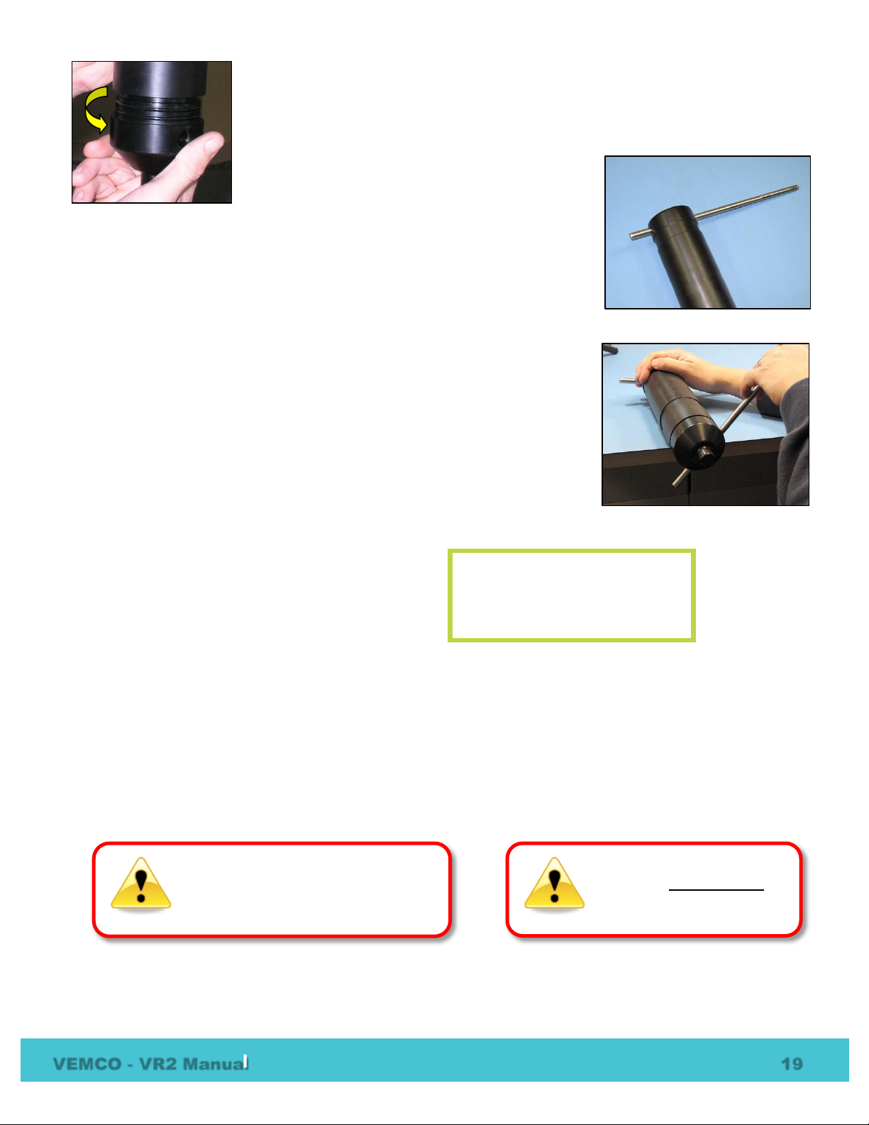
Each time an O-ring is
disturbed,
, it
must be checked
the unit is sealed again.
Improper care of the O-rings and their
mating surfaces can result in water
leaking into the receiver casing,
destroying the electronics.
6. Turn the end-cap in a counter-clockwise direction (when looking at the
hydrophone) with your hand until it becomes too hard to turn.
7. Place the VR2 on a clean, flat surface so the hydrophone is hanging over
the edge. DO NOT let the receiver fall off the surface.
8. Insert one steel rod into the hole that runs through the diameter of the case
near the flat end of the VR2.
9. Insert the other steel rod into the wider end of the Probe Hole on the end-
cap of the receiver. Make sure the rod is fully inserted or damage may
occur to the Probe Hole.
10. Place a hand on the back of the receiver to hold it in place.
11. Apply pressure to the rod in your hand to turn the end-cap in a clock-wise
direction when you are facing the hydrophone. The rod at the flat end of
the receiver acts as a brace while you apply pressure.
12. Continue moving the rod until the end-cap suddenly stops turning. DO
NOT continue to apply pressure on the rod or the receiver case will be
damaged. The gap between the end-cap and the outer cylinder will be
closed. Do not over tighten the end-cap or the receiver case will be damaged.
13. Remove the steel rods from the VR2 case.
14. Initialize the receiver (see section 3.5).
15. Deploy the VR2 receiver.
The VR2 must be initialized to
conduct a new study after the
battery has been replaced.
5.2 O-ring Care
O-rings located in the end-cap of the VR2 case are crucial to the watertight seal of the receiver. Each time a n
O-ring is disturbed, for any reason, it must be checked before the unit is sealed again. Something as simple
as a stray hair could be the difference bet ween a successful study and a damaged receiver.
Just as the O-rings are vital to a good seal, so are the O-ring surfaces. These surfaces hold the O-ring in
position and must also be clean and damage free or the VR2 case could flood with water.
for any reason
before
VEMCO - VR2 Manual 19
Page 23
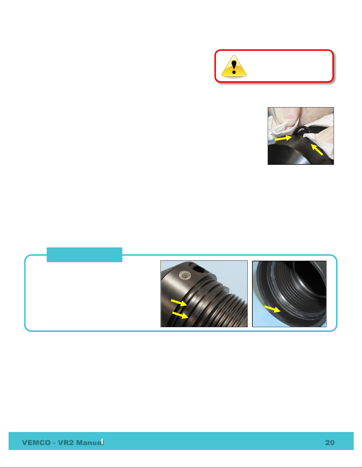
Do not use a sharp object
near O
surface could be damaged.
An O
touches. The VR2 has three, the two
grooves between the threads and the LED
on the end cap and the first flat section
inside the Outer Cylinder (2 cm).
O-Ring Surfaces
5.2.1 Remove O-rings
The O-rings must be removed from their grooves to allow the
O-rings and the grooves to be inspected and cleaned. Don’t use
a sharp object when removing the O-rings, which may damage
the groove surface.
-ring surfaces. The
1. Use a lint-free cloth to grip two points on the O-ring with your thumb and finger, approximately 5 cm
apart. It’s best to start with the O-ring farthest from the case threads.
2. Pull your thumb and finger towards each other while maintaining your grip on the
O-ring. This requires pressure against the O-ring and should produce a loop of
exposed O-ring.
3. Grab the exposed O-ring and pull it away from the end cap, so it moves along the
body of the receiver.
4. Repeat Steps 1 -3 for the other O-ring.
5. Clean any O-ring grease on the plastic casing.
5.2.2 Clean O-ring Surfaces
The O-ring surfaces must be clear of all debris and dirt.
An O-ring surface is any surface the O-ring t ouches. The VR2 has three, the two grooves the O-ring s sit in
and the smooth area inside the Outer Cylinder that sits between the threads and the end of the cylinder.
-ring surface is any surface the O-ring
It is vital that all O-ring surfaces are clean and damage free or water may work its way inside the case and
destroy the electronics within th e VR 2 receiver.
VEMCO - VR2 Manual 20
Page 24
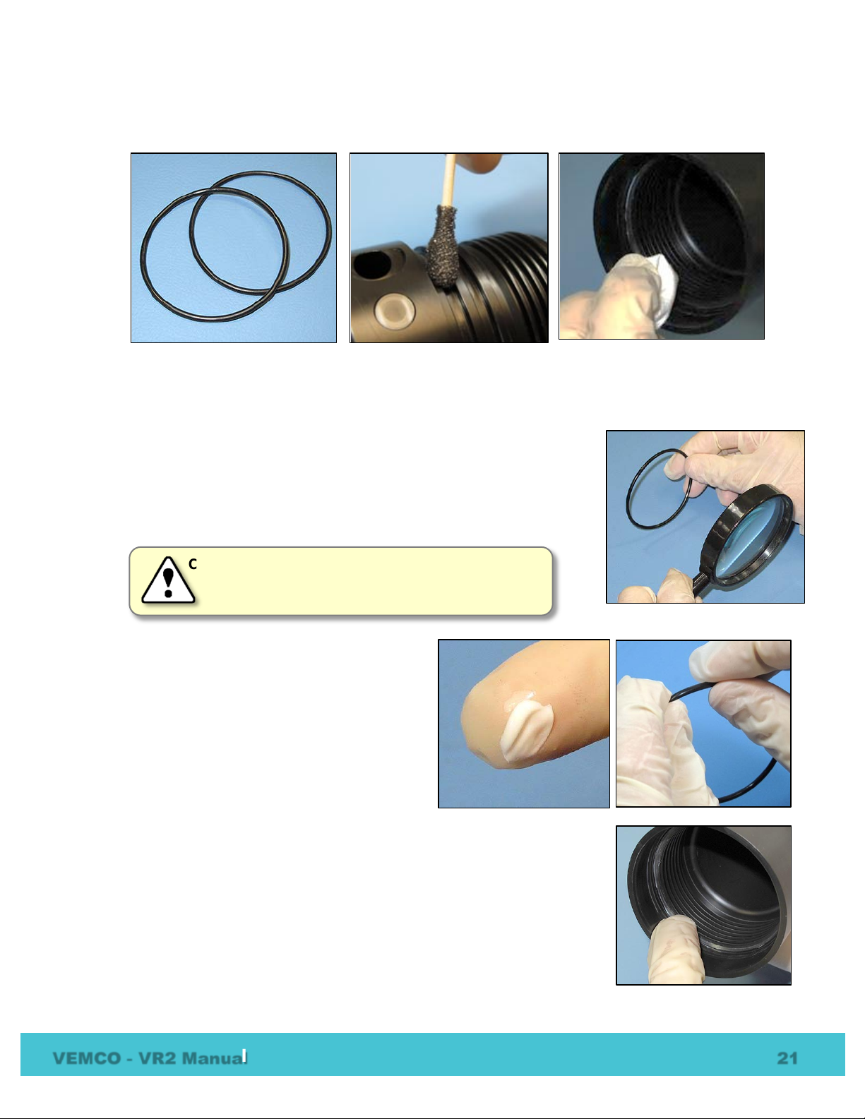
CAUTION: O-rings can stretch with cont i nued handling.
1. Use a lint-free cloth to clean the old grease and any debris from the O-rings and the O-ring surfaces. A
lint-free swab is very helpful for cleaning inside the grooves.
2. Inspect the O-ring surfaces for any scratches or debris – use a magnifying glass and a bright light.
Scratches in the O-ring groove would allow water to bypass the O-ring. If you find debris (dirt, dust,
hair, etc) inside a groove, then use a lint-free swab to remove it. If you find a scratch in any of the O-ring
surfaces, then contact our Support department.
3. Inspect the O-rings for debris and for any damag e. If there is any question
about the condition of an O-ring, we recommend it be replaced rather than
risk damage to the receiver and therefore your data. O-rings can be
purchased for VEMCO or locally. The replacement O-rings must be
PARKER #2-143 O-RING, 70 Bn NITRILE.
We advise that undamaged O-rings not be used
for more than three deployments.
4. Use your gloved fingers to evenly spread O-ring
grease (we suggest Molykote 55) over t he entire
surface of the O-ring until the O-ring is slippery
but doesn’t have clumps of grease on it. Too
much grease can cause an O-ring to “pop” out of
the groove while the case is being closed, giving
little protection from water entering the VR2.
5. While you have grease on your glove, spread a very thin layer of the grease –
enough to make the area appear shinny – around the O-ring surface on the
inside of the Outer Cylinder (the smooth area bet ween the threads and the end
of the case). You shouldn’t be able to see grease globs or streaks. This thin
layer of grease will make screwing the two pieces together again much easier
and will also help to create a better seal.
VEMCO - VR2 Manual 21
Page 25
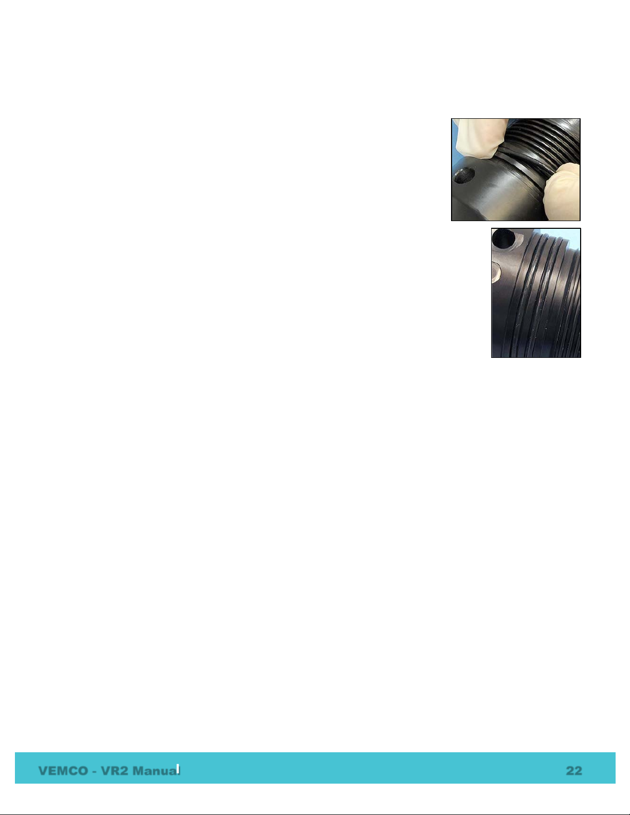
5.3 O-ring Installation
Now that the O-rings and O-ring surfaces are clean and prepared, we’re ready to install the new O-rings into
the case.
1. Slowly move one of the O-rings along the body of the VR2 to the end cap and
carefully lift it over the threads.
2. Push the O-ring into the first O-ring groove and check the circumference of
the receiver to make sure the entire O-ring is in the groove.
3. Slowly move the second O-ring over the VR2’s body, over the threads, and into the
remaining groove. Check that it’s entirely in the groove.
4. Clean any grease that may have gotten on the body of the receiver.
5. Place the receiver on a clean surface so the O-ri ngs remain debris and damage free.
5.4 Storage
Remove the battery from the receiver (section 5.1.2) to stop the VR2 from recording. This will prevent the
possibility of recording pings from noise sources during storage while saving battery life.
Be sure to store the VR2 in a safe location where the case will not be damaged. Also be sure th e temperature
of the receiver during storage does not exceed the operating temperature specified in section 9.3.
Do not initialize the VR2 prior to storage (data is not erased). Backup all offloaded data as soon as possible.
VEMCO - VR2 Manual 22
Page 26
6 Additional Information
6.1 Flash Memory
The VR2 receiver uses a non-volatile Flash Memory (memory that can retain stored information even when
not powered) to store valid detections of coded transmitters and the date/time at which the detection was
recorded. The VR2 will not continue to record r eceived data once the memory is full. The memory is
capable of storing more than 300,000 valid detections. If a valid detection is received every 45 seconds it will
require approximately 156 days to fill the VR2 memory (see table below).
Time required to fill 2 MB memory based on various detection times.
Valid detection every… Time to fill VR2 memory
30 Sec 104 days
45 Sec 156 days
60 Sec
90 Sec
208 days
312 days
6.2 Resume Study
After a VR2 Receiver has been initialized, it will continue to record data until the power is disconnected
(battery removed) except when it’s connected to the VR PC interface. When the VR PC interface’s probe is
inserted in the VR2 receiver, the study is stopped. Sixty seconds after the probe is removed from the receiver
the study will resume, unless the memory is full. This feature simplifies the process of downloading data
while in the field because receivers don’t need to be re-initialized before being re-deployed. If a study is
completed when the data is downloaded and the VR2 will not be deployed in the near future, remove the
battery from the receiver (see Battery secti on) to stop the receiver from recording.
6.3 Change VR PC Battery
To change the 9 volt battery in the VR PC computer interface:
1. Disconnect the serial cable between the VR PC and the computer.
2. Turn the interface case over and slide the b attery cover away from the case.
3. Remove the battery from the case and disconnect it.
4. Connect the replacement 9 volt alkaline battery,
5. Insert the battery into the case and replace the battery cover.
VEMCO - VR2 Manual 23
Page 27
7 Common Questions
7.1 VUE related questions
7.1.1 What is initialization?
Initialization, which is also referred to as starting a study, is a vital step required to configure your receiver
correctly. A VR2 receiver will not detect tags until it is initialized. During initialization, you can also input
the station name (location) where the VR2 will be deployed and set the receiver clock based on your
computer clock. The receiver clock is always updated based on your PC clock during
the initialization process. This information will be resident with the VR2 and will be
available during offload, regardless of whether you use the same computer or not.
Initialization also erases the receiver’s memory. Offload data from your receiver
before initializing it. When data is offloaded from a receiver, the VRL file created contains information about
how the receiver was initialized.
7.1.2 Why does VUE create two .vrl file types?
VR2 will not
detect tags until
it is initialized
When a VR2 is offloaded, VUE creates a detection file and an RLD data file. Both files have the “.vrl”
extension. VUE only imports the detection vrl file (e.g., VR2_2693_20120120_1.vrl or
VR2_2693_20120120_1.vrl ). The RLD data file (VR2180-RLD_2693_20120120_1.vrl or VR2RLD_2693_20120120_1.vrl) is used by VEMCO for diagnostic purposes and should be archived in case it is
required by our Support Department. The RLD data files have the letters “RLD” in the filename.
7.1.3 What Date/Time format is my data stored in the receiver and
displayed in VUE?
All detection data and events are stored i n the receiver in UTC (Coordinated Universal Ti me). UTC time is
calculated by your PC and stored in your receiver during initialization. Provided your computer time and the
Time Zone settings are correct and match, i.e. your computer time is correct for the time zone you have
selected, then your detection data will be stored in the correct UTC format at the time of initialization and
data offload. Exception: If a VR2 is initialized u sing older VRPC software the VR2 will likely store the local
time.
In VUE, your data is also stored in UTC format in the database. You can choose to display your detections in
UTC, your local time or in a different time zone. I t is important to know that regardless of what ever display
format you choose the detection data is stored in UTC in the VUE database.
Export: All detection data is exported only in UTC unless specified otherwise in VUE by selecting OPTIONS
– EXPORT – CUSTOM
Important: If you are importing detection data from an older format detection file (e.g., VR2*.000) you must
specify the time zone offset used when the receiver was initialized. Earlier VR2 receiver s were most often
initialized with the current PC local ti me unless the PC local time was set to UTC. Please co ntact us if you
VEMCO - VR2 Manual 24
Page 28
need assistance. Once these older files are imported into VUE, a new .vrl file will be created an d all
timestamps will be in UTC.
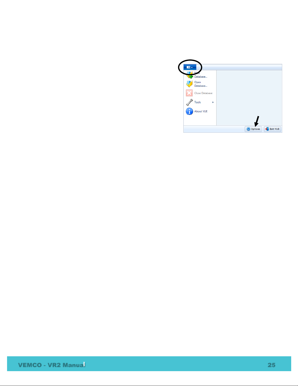
7.1.4 How do I open the Options window?
The Options window is accessed by selecting the VUE menu
(circled in picture at right) and clicking the “Options” button at
the bottom of the menu box (see arrow in picture at right). The
Options window contains the following tabs: Display , Offl oad,
Export, Devices, and Other.
7.1.4.1 Display of location, units, and time
The Display tab in the Options window allows the user to select
the format of various display options.
7.1.4.2 Offload data settings
The Offload tab in the Options window allows the Receiver Offload Storage Folder location to be changed by
clicking the “Change” button and selecting a different storage location for the offloaded data files. The
default directory location is created in “…\My Documents\Vemco\VUE\ReceiverLogs\”
Also, the offloaded file format can be chosen f r om the choices listed: VRL files only, VRL fi les and CSV
files, or VRL files and legacy VR2 files.
7.1.4.3 CSV file settings
The format of the CSV files created in VUE can be changed from the default format to either the Version 1.0
format or to a custom format in the Export tab of the Options window.
7.1.4.4 Other settings
The Other tab in the Options window allows the last database that was launched in VUE t o be automatically
open the next time VUE is opened. Also, th e default options settings and the hidden dialogs can be restored
to their default settings.
VEMCO - VR2 Manual 25
Page 29

7.2 VR2 related questions
7.2.1 How much detection range can I expect from my tags and receivers?
Detection range depends on so many factors that it is difficult to estimate without k nowledge of the
environment and prior experience with telemetry. Range depends on transmission power, signal absorption,
line of sight, reflection/refraction, multipath and environmental noise (man-made & natural), and the
receiving quality of the receiver/hyd r ophone. Typically areas that have clear wat er , sand or silt flat bottoms
and low current exhibit the greatest ranges. Conversely, areas with turbid water, complex rocky bottom
topography and high current exhibit low ranges. In all cases, extreme weather events and periods of high
wind (waves) may significantly reduce r ange.
In most cases greater transmission power output (dB) results in greater range. For example, in good
conditions a V7-VR2 range test could yield a range of 300-400 m and a V16-VR2 test could yield ranges of
800-1200 m. There are some exceptions where high power and a reflective and low noise environment may
cause detection breakdowns.
Please try our range calculator at www.vemco.com/customer-service/?cs-tutorials
a guide. One should always perform range testing to det ermine appropriate receiver spacing. F or the
enthusiast who wants to learn more about sound propagation try the widely accepted reference on underwater
sound by Urick (1983). (Urick, Robert J. Principles of Underwater Sound, 3rd Edition. New York. McGrawHill, 1983.).
7.2.2 How long will my VR2 battery last?
, but only use the results as
The VR2 receiver will typically last 15 months on a single Tadiran lithium battery (model TL-5930/F). TIP:
Write the installation date on the battery so you know how long the battery has been in use. We recommend
changing the battery within 12 months.
7.2.3 Does receiver orientation matter?
Generally, in most cases we recommend that a VR2 should be orientated with the hydrophone looking
upwards. This is typically because receivers are commonly moored closer to the seafloor than the surface. In
some situations it may be beneficial to mount the receiver with the hydrophone pointing towards the sea floor.
If a receiver is mounted near the surface or a considerable distance from the sea floor and if the researcher is
monitoring benthic creatures a bottom looking receiver may perform better because your tagged animals will
not be in a shadow zone (under the receiv er ) . If receiver orientation is a concern we recommend that you
perform range tests using both orientations.
7.2.4 At low tide my VR2 receiver will be exposed to d irect sunlight, does
this matter?
The VR2 receiver has a recommended op er ating temperature of between -5 to 40°C. If ther e is a chance that
your receiver will exceed either of these temperatures please consider another location for the receiver. Keep
in mind that direct sunlight on the black case can cause the receiver’s internal temperatu r e to be much higher
than the ambient temperature.
VEMCO - VR2 Manual 26
Page 30
8 Troubleshooting
8.1 VUE related troubleshooting
8.1.1 I cannot connect to my VR2 receiver
First, confirm that the 9 Volt battery in the VR PC does not need to be replaced. If this was no t the problem,
then confirm that the VR PC is connected to the correct Com port on the PC. Also, it’s possible that the
probe on the VR PC is not inserted far enough into the Probe Hole on the VR2. If you are still unable to
communicate with the unit, please conta ct VEMCO to receive RMA information and send the unit back to
VEMCO for assessment/repair.
8.1.2 These detected ID’s don’t belong to me
We would be very pleased to help connect you with th e owners of any unknown IDs. Please send a list of the
unknown ID’s and all associated receive r .vrl files to the VEMCO support team. VEMCO will first review
the data to identify false detections and provide you with a false detection repo r t. Then we’ll contact the tag
owners for all the valid detections and request that they contact you directly . Pl ease indicate if you are
willing to release your email address.
8.2 VR2 case related troubleshooting
8.2.1 The threads have been damaged
It’s very important that the threads on the end-cap are not dented or the outer cylinder will not thread onto the
end-cap properly. If the threads on the end -cap are slightly dented, use a sharp knife, such as an X-Acto
knife, to remove the deformed plastic until the sides of the thread are smooth and below the normal line of the
thread. It is important that there is nothing sticking out of the thread to damage the thread on the outer
cylinder or prevent the case from closing.
8.2.2 I think the case might be pressurized
When handled correctly, the VR2 pressure case and seal have a static depth rating of 500 meters (730 psi). If
the receiver experiences a pressure greater than this, then water may enter the case. NOTE: Physical shocks
to the receiver, such as bumping into a solid object, when it is at any depth can result in a considerably higher
pressure on the casing than just the depth pressure. Also, if the O-rings or their mating surfaces are dirty or
damaged, then water may enter the receiver case.
If water enters the receiver case under hig h pressure and the Release Valve was unabl e to open and equalize
the pressures, then some water and compressed air may still be in the case when it is return ed to the surface.
This can be identified by its increased weight and a sloshing sound when the case is moved. The VR2 case
will also be very difficult to open, if at all possible. If you are suspicious there is compressed air in the
VEMCO - VR2 Manual 27
Page 31
receiver case, then check for air or water leaking from seam in the case where the end-cap and outer cylinder
meet.
To check for... then...
water leakage
air leakage
dry the seam completely and watch for drops of water around
the seam
spread soapy water around the seam and watch for bubbles
indicating air escaping
If air and/or water are found leaking from the receiver case, do not attempt to remove the end-cap. Instead,
place the receiver in a safe place and cover it wi th a protective layer of towels, tarpaulins, etc. until the
leaking stops. If water is still in the case after t he air and/or water have finished leaking from the
case, then attempt to open the case with the steel rod kit. If it will open, do so very sl owly to allow
the compressed air to escape. If the case will n ot open using the steel rods, then it is under a greater
pressure than will allow the case to open. Contact VEMCO for further instructions.
When the pressure has been released from the VR 2 case, carefully unscrew the end-cap from the outer
cylinder (section 5.1.1). Use fresh water to rinse the internal parts of the VR2 while avoiding skin contact
with any battery electrolyte that may have escaped from the battery.
Do not attempt to re-use the VR2 receiver after water has been inside the case. The internal casing protecting
the electronics is not waterproof and the electronics will be destroyed by contact with water.
VEMCO - VR2 Manual 28
Page 32

9 Appendix
9.1 Cleaning Instructions
Clean the VR2 with a damp cloth and mild detergent. Do not use solvents. Do not use a scraper or abrasive
cleaner on the LED window or the seal surfaces.
9.2 Contact Information
Product manufactured by
VEMCO Division
AMIRIX Systems Inc.
20 Angus Morton Drive
Bedford, Nova Scotia
Canada B4B 0L9
Phone: +1-902-450-1700
Fax: +1-902-450-1704
Web Site:
www.vemco.com
VEMCO - VR2 Manual 29
Page 33
Dimensions
308 mm (12.125") overall length x 73 mm (2.875") diameter
Shipping & storage
temperature
1 - Tadiran TL-5930/F Lithium Inorganic battery or equivalent, 3.6 Volts
U.L. Component Recognition, MH 12193
Standard method: 5 non-reusable lashing cabl e ties, 388 mm (15.25") long,
HWE 507450).
WARNING
The VR2
(730 psi). Physical
shocks to the receiver, such as bumping into a soli d object, when it is at any depth can result
in a considerably higher pressure on the casing than just the depth pressure and water may
enter the VR2 case. If the O
may also enter the receiver case. If you are suspicious that water has entered the receiver,
then follow the suggestions in the Appendix f or troubleshooting a pressurized case.
9.3 VR2 Specifications
Receive Frequency 69.0 kHz
Operating temperature -5°C to +40 °C; Water in which VR2 is deployed must not freeze.
-5°C to +50°C
• Nominal capacity @ 4 mA, to 2 V 19 Ah
• Rated voltage 3.6 V
Battery
Battery Life Approximately 15 months (using Tadiran TL-5930/F)
• Maximum recommended c ontinuous current 230 mA
• Maximum pulse current ca pabi li ty 500 mA
• Weight 105 g (3.7 oz)
• Li metal content approx. 5 g
Memory 2 MB Flash memory (approx. 300000 detections)
Static depth rating 500 meters (730 psi)
Attachment:
7.5 mm (0.3") wide, UV protected, 120 lb tensile strength (VEMCO number
pressure case and seal have a static dept h rating of 500 meters
-rings or their mating surfaces are dirty or damaged, then water
VEMCO - VR2 Manual 30
Page 34

AMIRIX Systems Inc.
9.4 Warranty and Disclaimer
WARRANTY
AMIRIX Systems Inc., doing business under its trade name VEMCO, provides a one (1) year warranty period for the Product from date of shipment.
VEMCO warrants that on the date of shipment all Products manufactured by VEMCO are free from defects in material and workmanship under normal use and service. This warranty
applies to the components necessary for equipment upgrades, i.e. the VR1/VR2 to VR2W upgrade. With respect to transmitter products, while VEMCO is able to predict battery life with
some certainty, VEMCO cannot guarantee that these Products will remain functional while submerged for extended periods of time. This warranty does not apply to any equipment,
materials or design supplied by Buyer or a third party; re-battery services provided by VEMCO; Products for which VEMCO has not received payment; problems that results from: external
causes such as accident, abuse, misuse; servicing not authorized by VEMCO; usage not in accordance with Product instructions; failure to follow the Product instructions or failure to
perform preventative maintenance; usage of accessories, parts or components not supplied by VEMCO.
This warranty shall survive delivery only on the conditions and subject to the limitations set forth below.
NOTICE PERIODS
To receive a warranty remedy for a Product, Buyer must contact VEMCO’s Customer Support Department during the warranty period to receive the Return Material Authorization (“RMA”)
instructions. Each defective Product returned for warranty remedy must be shipped at the Buyer’s expense according to the RMA instructions and must include reasonable proof that the
claimed defect is due to a matter embraced within the warranty set forth above and that such defect did not result from any act or omission of Buyer, including but not limited to any failure
to operate and maintain the Product in accordance with VEMCO’s applicable written instructions.
REMEDY
VEMCO’s liability, and the Buyer’s exclusive remedy under this warranty, as to a defect in material or workmanship, is limited to the repair of such defect in the accessory, equipment or
part in which the defect appears or, at VEMCO’s option, to the replacement of such accessory, equipment or part with a similar item free from defect. As to any item repaired by VEMCO
or furnished as a replacement by VEMCO, VEMCO’s liability and the Buyer’s exclusive remedy to the repair or replacement of such item for any further defect in material or workmanship,
provided VEMCO receives written notice at Halifax, Nova Scotia, of such further defect from BUYER within ninety (90) days after the repaired or replaced item is shipped to BUYER and
provided that BUYER returns same to VEMCO as provided under “Notice Periods”.
RETURNED ITEMS
All repairs, replacements and corrections described above shall be performed by VEMCO at its plant at Halifax, Nova Scotia, or at such other place as may be mutually agreeable, and
with reasonable care and dispatch in order that the Product, accessory, equipment or part will not be kept out of service longer than necessary. Return to BUYER of a repaired,
replacement, or corrected accessory, equipment, part or Product shall be at VEMCO’s expense. Title to and risk of loss of the Product, accessory, equipment, or part returned to VEMCO
pursuant hereto shall at all times remain with the BUYER, except that title to a returned accessory, equipment, part, or Product shall pass to VEMCO concurrently with shipment to
BUYER of any item furnished by VEMCO to BUYER as a replacement therefore. VEMCO shall have only such responsibility for any Product, accessory, equipment, or part owned by the
BUYER and in the possession of VEMCO as is chargeable by law to a bailee for hire, but shall not be chargeable for loss of use thereof.
WEAR AND TEAR
Normal wear and tear and the need for regular maintenance shall not constitute a defect under this warranty.
DISCLAIMER AND RELEASE
THE WARRANTIES, OBLIGATIO NS AND LIABILITIES OF VEMCO AND T HE REMEDIES OF BUYER SET F ORTH HEREIN ARE EXCLUSIVE AND IN SUBSTITUTION FOR, AND
BUYER HEREBY WAIVES AND RENOUNCES, ALL OTHER WARRANTIES AND OBLIGATI ONS OF VEMCO AND ANY ASSIGNEE OF VEMCO AN D ALL RIGHTS, CLAIMS AND
REMEDIES OF BUYER AGAINST VEMCO, EXPRESS O R IMPLIED, ARISING BY LAW OR OTHERWISE, WITH RESPECT TO ANY NON-PERFORMANCE OR DEFECT IN THE
PRODUCT OR IN ANY OTHER THING DELIVERED UNDER THIS AGREEMENT, INCLUDING BUT NOT LIMITED TO:
(A) ANY IMPLIED WARRANTY OF MERCHANTABILITY OR FIT N ESS FO R A PARTICULAR PURPOSE;
(B) ANY IMPLIED WARRANTY ARISING OUT OF COURSE OF PERFOR MANC E, COURSE OF DEALING OR USAGE OF TRADE;
(C) ANY OBLIGATION, LIABILITY, CLAIM OR REMEDY IN TORT, WHETHER O R NOT ARISING FROM THE NEGLIGENCE OF VEMCO OR ANY
ASSIGNEE OF VEMCO, ACTUAL OR IMPUTED;
(D) ANY OBLIGATION, LIABILITY, RIGHT, CLAIM, OR REMEDY FOR LOSS OF OR DAMAGE TO THE PRODUCT, FOR LOSS OF USE, REVENUE, O R
PROFIT WITH RESPECT TO THE PRODUCT; OR FOR ANY OTHER DIRECT, INCIDENTAL OR CONSEQUENTIAL DAMAGES; AND
(E) VEMCO MAKES NO REPRESENTATION THAT THE PROD UCT WILL NOT INFRINGE ANY PATENT OR OTH ER RIGHTS OF ANY PERSON AND
BUYER AGREES TO INDEMNIFY VEMCO AND HO LD VEMCO HARMLESS FROM ANY AND AL L CLAIMS AND LIABILITIES WI TH RESPECT TO
SAME TOGETHER WITH ANY CLAIMS AND LIABIL ITI ES WIT H RESPECT T O ANY I NF RIN GEMENT OF ANY PAT ENT OR O THER RI GH TS OF AN Y
PERSON ARISING AS A RESULT OF BUYER'S PRODUCT S, TEC HN O L O GY, ACTIVITIES, OR OTHERWISE.
LICENSE AGREEMENT
VEMCO grants to the Buyer a limited, personal license, with no right to sub-license, to use the Intellectual Property (“IP”) and Embedded Software in the manner set out in the
Documentation. The Embedded Software and IP are not sold to Buyer. All property rights, including Intellectual Property Rights, remain with VEMCO. All rights related to the Embedded
Software not expressly licensed to the Buyer are reserved to VEMCO. BUYER shall not permit any person other than BUYER and its employees to use or make use of the Embedded
Software and/or IP. BUYER shall not, and shall not permit any third party to, modify, adapt, translate, reverse engineer, decompile, disassemble, or create derivative works based on the
Embedded Software and/or IP. This license is assigned to the Product with which you have acquired the Embedded Software and/or IP. If the Product purchased is a Transmitter product,
be advised that the license life is equal to the operational life.
EXPORT
Products and associated materials supplied or licensed hereunder may be subject to various export laws and regulations. It is the responsibility or BUYER to comply with such laws and
regulations.
NEGOTIATED AGREEMENT
It is fully understood by the parties that the price of the Product and other mutual agreements of the parties set forth in this agreement were arrived at in consideration of this warranty,
SPECIFICALLY INCLUDING THE WAIVER, RELEASE AND R EN U NC IATION BY BUYER SET FORTH ABOVE (DISCLAIMER AND R EL EASE).
Warranty and Disclaimer
VEMCO - VR2 Manual 31
Page 35

9.5 Index
Battery
Replacement, 16
Specifications, 30
Case
Introduction, 2
Opening, 16
Parts, 2
Communication probe receptacle, 3
Deployment
Fact and Tips, 13
Mooring line attachment, 14
Initialization
VR2, 11
What is it?, 24
Memory
Flash, 23
Options
Offloaded file types, 25
Options window, 25
O-rings
Cleaning surfaces, 20
Installing, 22
Removing, 20
Resume Study, 23
Status Light (LED)
Flash meanings, 2, 3
Storage, 22
Testing
In-water, 6
VR PC
Battery, 23
VR2
Change Code Map, 12
Communicating, 8
Offloading Raw data, 25
Retrieve Data, 10
VUE
VRL file types, 24
VEMCO - VR2 Manual 32
 Loading...