

Page 1

VR100 RECEIVER
OPERATING MANUAL
DOC-4536-13
December 13, 2012
VEMCO, a Division of AMIRIX Systems Inc.
Page 2

AMIRIX Systems Inc.
Warranty and Disclaimer
WARRANTY
AMIRIX Systems Inc., doing business under its trade name VEMCO, provides a one (1) year warranty period for the Product from date of shipment.
VEMCO warrants that on the date of shipment all Products manufactured by VEMCO are free from defects in material and workmanship under normal use and service. This warranty
applies to the components necessary for equipment upgrades, i.e. the VR1/VR2 to VR2W upgrade. With respect to transmitter products, while VEMCO is able to predict battery life with
some certainty, VEMCO cannot guarantee that these Products will remain functional while submerged for extended periods of time. This warranty does not apply to any equipment,
materials or design supplied by Buyer or a third party; re-battery services provided by VEMCO; Products for which VEMCO has not received payment; problems that results from: external
causes such as accident, abuse, misuse; servicing not authorized by VEMCO; usage not in accordance with Product instructions; failure to follow the Product instructions or failure to
perform preventative maintenance; usage of accessories, parts or components not supplied by VEMCO.
This warranty shall survive delivery only on the conditions and subject to the limitations set forth below.
NOTICE PERIODS
To receive a warranty remedy for a Product, Buyer must contact VEMCO’s Customer Support Department during the warranty period to receive the Return Material Authorization (“RMA”)
instructions. Each defective Product returned for warranty remedy must be shipped at the Buyer’s expense according to the RMA instructions and must include reasonable proof that the
claimed defect is due to a matter embraced within the warranty set forth above and that such defect did not result from any act or omission of Buyer, including but not limited to any failure
to operate and maintain the Product in accordance with VEMCO’s applicable written instructions.
REMEDY
VEMCO’s liability, and the Buyer’s exclusive remedy under this warranty, as to a defect in material or workmanship, is limited to the repair of such defect in the accessory, equipment or
part in which the defect appears or, at VEMCO’s option, to the replacement of such accessory, equipment or part with a simila r item free from defect. As to any item repaired by VEMCO
or furnished as a replacement by VEMCO, VEMCO’s liability and the Buyer’s exclusive remedy to the repair or replacement of such item for any further defect in material or workmanship,
provided VEMCO receives written notice at Halifax, Nova Scotia, of such further defect from BUYER within ninety (90) days after the repaired or replaced item is shipped to BUYER and
provided that BUYER returns same to VEMCO as provided under “Notice Periods”.
RETURNED ITEMS
All repairs, replacements and corrections described above shall be performed by VEMCO at its plant at Halifax, Nova Scotia, or at such other place as may be mutually agreeable, and
with reasonable care and dispatch in order that the Product, accessory, equipment or part will not be kept out of service longer than necessary. Return to BUYER of a repaired,
replacement, or corrected accessory, equipment, part or Product shall be at VEMCO’s expense. Title to and risk of loss of the Product, accessory, equipment, or part returned to VEMCO
pursuant hereto shall at all times remain with the BUYER, except that title to a returned accessory, equipment, part, or Product shall p ass to VEMCO concurrently with shipment to
BUYER of any item furnished by VEMCO to BUYER as a replacement therefore. VEMCO shall have only such responsibility for any Product, accessory, equipment, or part owned by the
BUYER and in the possession of VEMCO as is chargeable by law to a bailee for hire, but shall not be chargeable for loss of use thereof.
WEAR AND TEAR
Normal wear and tear and the need for regular maintenance shall not constitute a defect under this warranty.
DISCLAIMER AND RELEASE
THE WARRANTIES, OBLIGATIONS AND LIABILITIES OF VEMCO AND THE REMEDIES OF BUYER SET FORTH HEREIN ARE EXCLUSIVE AND IN SUBSTITUTION FOR,
AND BUYER HEREBY WAIVES AND RENOUNCES, ALL OTHER WARRANTIES AND OBLIGATIONS OF VEMCO AND ANY ASSIGNEE OF VEMCO AND ALL RIGHTS,
CLAIMS AND REMEDIES OF BUYER AGAINST VEMCO, EXPRESS OR IMPLIED, ARISING BY LAW OR OTHERWISE, WITH RESPECT TO ANY NON-PERFORMANCE OR
DEFECT IN THE PRODUCT OR IN ANY OTHER THING DELIVERED UNDER THIS AGREEMENT, INCLUDING BUT NOT LIMITED TO:
(A) ANY IMPLIED WARRANTY OF MERCHANTABILITY OR FITNESS FOR A PARTICULAR PURPOSE;
(B) ANY IMPLIED WARRANTY ARISING OUT OF COURSE OF PERFORMANCE, COURSE OF DEALING OR USAGE OF TRADE;
(C) ANY OBLIGATION, LIABILITY, CLAIM OR REMEDY IN TORT, WHETHER OR NOT ARISING FROM THE NEGLIGENCE OF VEMCO OR ANY ASSIGNEE OF VEMCO,
ACTUAL OR IMPUTED;
(D) ANY OBLIGATION, LIABILITY, RIGHT, CLAIM, OR REMEDY FOR LOSS OF OR DAMAGE TO THE PRODUCT, FOR LOSS OF USE, REVENUE, OR PROFIT WITH RESPECT
TO THE PRODUCT; OR FOR ANY OTHER DIRECT, INCIDENTAL OR CONSEQUENTIAL DAMAGES; AND
(E) VEMCO MAKES NO REPRESENTATION THAT THE PRODUCT WILL NOT INFRINGE ANY PATENT OR OTHER RIGHTS OF ANY PERSON AND BUYER AGREES TO
INDEMNIFY VEMCO AND HOLD VEMCO HARMLESS FROM ANY AND ALL CLAIMS AND LIABILITIES WITH RESPECT TO SAME TOGETHER WITH ANY CLAIMS AND
LIABILITIES WITH RESPECT TO ANY INFRINGEMENT OF ANY PATENT OR OTHER RIGHTS OF ANY PERSON ARISING AS A RESULT OF BUYER'S PRODUCTS,
TECHNOLOGY, ACTIVITIES, OR OTHERWISE.
LICENSE AGREEMENT
VEMCO grants to the Buyer a limited, personal license, with no right to sub-license, to use the Intellectual Property (“IP”) and Embedded Software in the manner set out in the
Documentation. The Embedded Software and IP are not sold to Buyer. All property rights, including Intellectual Property Rights, remain with VEMCO. All rights related to the Embedded
Software not expressly licensed to the Buyer are reserved to VEMCO. BUYER shall not permit any person other than BUYER and its employees to use or make use of the Embedded
Software and/or IP. BUYER shall not, and shall not permit any third party to, modify, adapt, translate, reverse engineer, decompile, disassemble, or create derivative works based on the
Embedded Software and/or IP. This license is assigned to the Product with which you have acquired the Embedded Software and/or IP. If the Product purchased is a Transmitter product,
be advised that the license life is equal to the operational life.
EXPORT
Products and associated materials supplied or licensed hereunder may be subject to various export laws and regulations. It is the responsibility or BUYER to comply with such laws and
regulations.
NEGOTIATED AGREEMENT
It is fully understood by the parties that the price of the Product and other mutual agreements of the parties set forth in this agreement were arri ved at in consideration of this warranty,
SPECIFICALLY INCLUDING THE WAIVER, RELEASE AND RENUNCIATION BY BUYER SET FORTH ABOVE (DISCLAIMER AND RELEASE).
© (2012) AMIRIX Systems Inc. All rights reserved. The information contained herein includes information which
is confidential and proprietary to AMIRIX Systems Inc. and may not be used or disclosed without prior written
consent of AMIRIX Systems Inc.
DOC-004536-13
Page 3

ATTENTION
It has come to VEMCO's attention that in rare instances it
is possible for the USB interface chips in certain computers
to experience permanent component failure when connected
to a USB device. These failures, which may relate to electric
static discharge damage, are not related to the specific USB
device connected to the computer and have been reported to
occur with cameras, scanners, printers, pocket PC
handheld devices, and MP3 players.
To reduce the risk of damage to the computer, some
computer manufacturers have recommended connecting
USB devices through a powered hub, rather than directly to
the computer. We have confirmed that the Dlink DUB-H4
USB 2.0 powered hub will allow the VR100 to operate
correctly.
We hope this information is helpful.
Warning
Permanent hearing loss may occur if the headphones or
internal speaker is used at high volume. Set the volume to a
safe level. Avoid turning up the volume to block out noisy
surroundings.
Warning
If the VR100 is not used in the manner specified by the
manufacturer, protection may be impaired.
Page 4

TABLE OF CONTENTS
1 INTRODUCTION ................................................................................................................................. 6
1.1 ABOUT VEMCO ............................................................................................................................. 6
1.2 SYSTEM REVIEW .......................................................................................................................... 6
1.3 USING THIS MANUAL ........................................................................................................................ 7
2 APPLICATIONS ................................................................................................................................... 8
2.1 QUICK SETUP .................................................................................................................................... 8
2.2 COMMON APPLICATIONS .................................................................................................................. 9
2.2.1 Set up a channel to monitor a continuous pinger ...................................................................... 9
2.2.2 Set up a channel to monitor a continuous sensor transmitter .................................................... 9
2.2.3 Set up a channel to monitor a coded tag .................................................................................. 10
2.2.4 Manually tracking a continuous pinger ................................................................................... 11
2.2.5 Manually tracking a coded tag ................................................................................................ 12
2.2.6 Enter slope and intercept for a continuous one-sensor transmitter .......................................... 13
2.2.7 Enter slope and intercept for a continuous two-sensor transmitter ......................................... 13
2.2.8 Enter slope and intercept for a coded sensor tag ..................................................................... 14
2.2.9 Take a GPS reading ................................................................................................................. 15
2.2.10 View Used Memory Level ...................................................................................................... 15
2.2.11 Clear VR100 Memory ............................................................................................................. 16
2.2.12 Using Signal Strength and Gain when tracking ...................................................................... 16
3 HARDWARE ....................................................................................................................................... 17
3.1 CASE ............................................................................................................................................... 17
3.1.1 Opening Case .......................................................................................................................... 17
3.1.2 Connectors............................................................................................................................... 18
3.1.2.1 Using connectors .............................................................................................................. 18
3.1.2.2 Using protective caps ....................................................................................................... 19
3.1.3 VR100 Front panel .................................................................................................................. 20
3.1.3.1 VR100 Front panel Explanations ..................................................................................... 21
3.2 ATTACHMENTS ............................................................................................................................... 22
3.2.1 Hydrophone ............................................................................................................................. 22
3.2.2 USB Cable ............................................................................................................................... 23
3.2.3 Headphones ............................................................................................................................. 24
3.3 MAINTENANCE ............................................................................................................................... 25
3.3.1 Charging Battery ..................................................................................................................... 25
3.3.1.1 Charge Indicator Lights ................................................................................................... 26
3.3.1 Maximizing Battery Service Life ............................................................................................ 27
3.3.2 Long-Term Storage ................................................................................................................. 27
4 OPERATION ....................................................................................................................................... 28
4.1 MAIN MENU .................................................................................................................................... 29
4.1.1 Main Menu Explanations ........................................................................................................ 29
4.2 MONITOR ......................................................................................................................................... 31
4.2.1 Monitor Screen Explanations .................................................................................................. 31
4.3 CONFIGURE ..................................................................................................................................... 33
4.3.1 Channel (1) .............................................................................................................................. 35
4.3.1.1 Enable a Channel ............................................................................................................. 35
Page 5

4.3.1.2 Configure channel ............................................................................................................ 35
4.3.1.2.1 Configure a Channel for a Continuous Pinger: ............................................................ 36
4.3.1.2.2 Configure a Channel for Coded Tags: .......................................................................... 36
4.3.1.2.3 Configure a Channel for Continuous Sensor transmitters (1 or 2 sensors): ................ 37
4.3.1.3 View Channel Configuration ........................................................................................... 37
4.3.2 System (2) ............................................................................................................................... 38
4.3.2.1 Time (2-1) ........................................................................................................................ 38
4.3.2.2 Contrast (2-2) ................................................................................................................... 39
4.3.2.3 Backlight (2-3) ................................................................................................................. 40
4.3.2.4 Battery (2-4) ..................................................................................................................... 40
4.3.2.5 Units (2-5) ........................................................................................................................ 40
4.3.2.6 Version (2-6) .................................................................................................................... 41
4.3.2.7 Reset to Factory Defaults (2-7) ........................................................................................ 41
4.3.3 Code Maps (3) ......................................................................................................................... 42
4.3.3.1 Understanding Code Maps ............................................................................................... 42
4.3.3.2 Viewing Code Maps ........................................................................................................ 42
4.3.4 Sensor Transmitters (4) ........................................................................................................... 43
4.3.4.1 Setting Up Coded Sensor Transmitters (4-1) ................................................................... 43
4.3.4.2 Setting Up One-sensor Continuous Sensor Transmitters (4-2) ........................................ 44
4.3.4.3 Setting Up Two-sensor Continuous Sensor Transmitters (4-3) ....................................... 44
4.3.5 Log (5) ..................................................................................................................................... 45
5 APPENDIX ........................................................................................................................................... 47
5.1 ADDITIONAL INFORMATION............................................................................................................ 47
5.1.1 GPS ......................................................................................................................................... 47
5.2 DETECTION PARAMETERS .............................................................................................................. 49
5.3 GLOSSARY ...................................................................................................................................... 50
5.4 TROUBLESHOOTING ........................................................................................................................ 51
5.5 VR100 HARDWARE VERSIONS ....................................................................................................... 52
5.6 SPECIFICATIONS .............................................................................................................................. 53
5.7 CLEANING INSTRUCTIONS .............................................................................................................. 53
5.8 CONTACT INFORMATION ................................................................................................................ 54
6 INDEX .................................................................................................................................................. 55
Page 6

1 INTRODUCTION
1.1 ABOUT VEMCO
VEMCO, a division of AMIRIX Systems Incorporated, is a leader in the design and manufacture of
oceanographic research tools and systems since 1979. VEMCO's product line ranges from miniature
acoustic transmitters and data loggers to large tracking, positioning, and monitoring systems. Data
communication methods include acoustic telemetry, radio modem, and under-water modem.
Please contact us at: www.vemco.com
1.2 SYSTEM REVIEW
The VR100 is a general-purpose ultrasonic, splash-resistant, receiver designed for manual tracking of
aquatic animals from small boats or for recording laboratory data. Its hardware architecture has been
developed to support a wide range of applications and transmitter types. It replaces the VR60 receiver.
All the VR100’s Digital Processing and Controller Functionality is software based and can be updated in
the field from a laptop. This allows new features, such as specialized tag detection algorithms and support
for new tag types, to be added during the life of the product and without the product having to return to the
factory.
The VR100 can detect continuous and coded tags on eight separate frequencies and at the same time. It
can also store the detections, along with the date/time and GPS location of the receiver at the time of the
detection, to be loaded to a computer for viewing or analysis. The communication between the computer
software and the VR100 travels through a supplied USB cable.
The internal gel-cell rechargeable battery can operate for approximately 12 hours with the backlight off
under normal operating conditions. Operating time with the backlight on is shorter. The VR100 can also
be operated while the battery is being charged from the supplied AC adapter or an external DC source,
allowing the receiver to continue to operate during the charging process. However, for the best noise
performance, the VR100 should be disconnected from the PC and charger as these devices can sometimes
add unwanted noise to the receiver.
The VR100 receiver is designed to operate with a hydrophone containing a high gain, low noise preamplifier powered by the receiver. An omni-directional hydrophone is provided as a standard accessory
(VH165). A high frequency omni-directional hydrophone (VH180) optimized for use with 180 kHz tags is
available as an option. The optional VH110 directional hydrophone enables the VR100 receiver to locate
and track a transmitter (see Applications, section 2).
Page 7
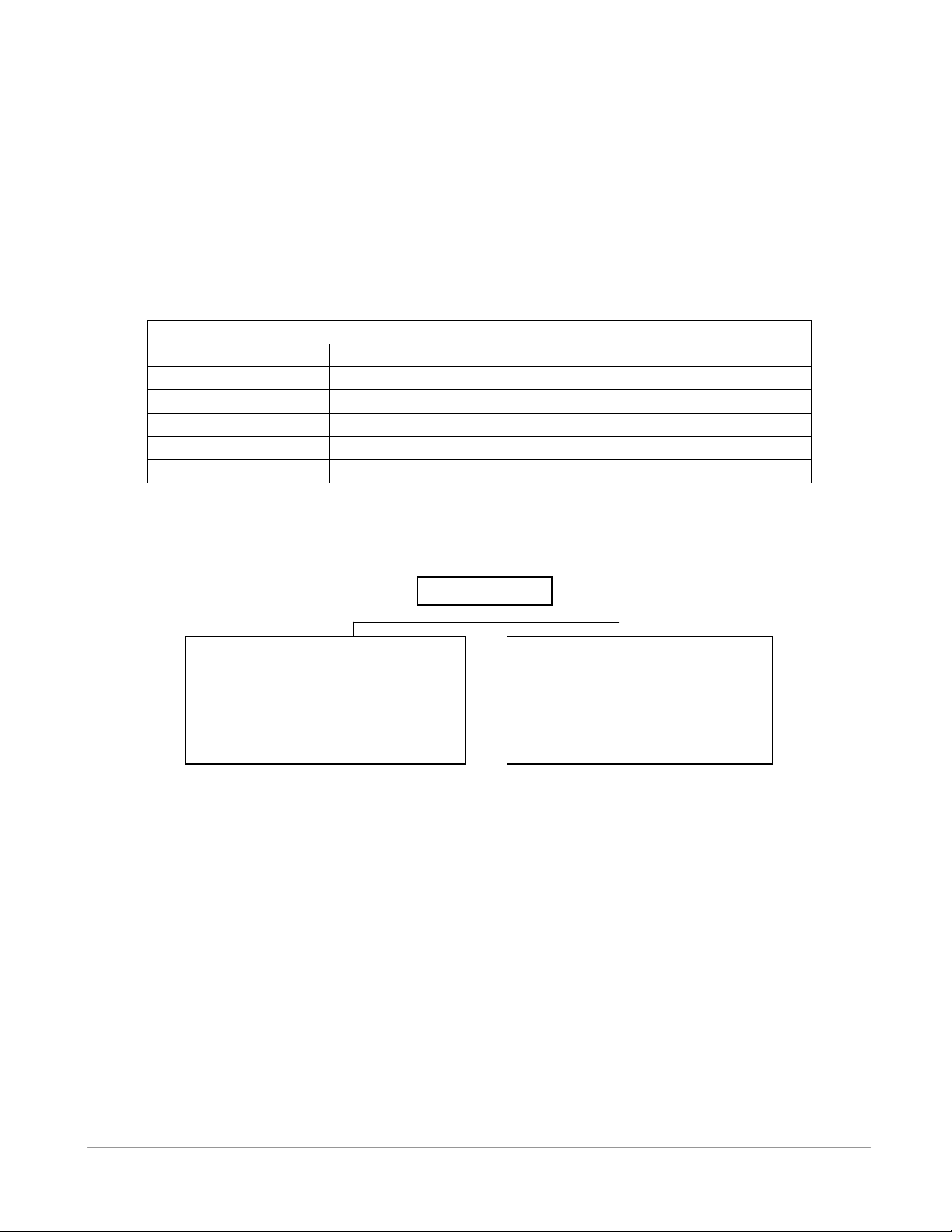
Table 1.3-1: Sections contained in this manual.
Section
Description
Introduction
Introduction to the VR100 and this manual.
Applications
Information on how to use the VR100 receiver.
Hardware
The VR100 case and attachments.
Operation
Information on how to use the buttons and LCD display.
Appendix
A glossary and additional information.
TAG
PINGER
These are tags that do not contain a
sensor and don’t transmit data information.
Pinger information is not entered in the
receiver.
SENSOR TRANSMITTER
These are tags that contain at least one
sensor. They transmit the sensor data.
Sensor transmitter information must be
entered in the receiver.
1.3 USING THIS MANUAL
This manual, the VR100 Operating Manual, contains the necessary information to care for the VR100
receiver and use it as a stand-alone unit. The receiver can be connected to a computer running the VR100
software and the necessary details are contained in the VR100 Software manual.
This manual is broken into major sections for easier use of the information found in the manual. These
sections, and a brief explanation, are listed in Table 1.3-1.
The manual refers to tags, pingers, and sensor transmitters. The relationship these three terms have with
each other is shown in the diagram below. A tag can be either a pinger or a sensor transmitter.
VEMCO – VR100 Receiver Operating Manual – Page 7
Page 8

2 APPLICATIONS
2.1 QUICK SETUP
The list below gives the order of actions needed to set up and use the VR100 receiver. The steps may
reference sections in this manual that contain more details about that step.
1. Open the lid of the VR100 case (see section 3.1.1).
2. Verify that the receiver is off by pressing the OFF button (see section 3.1.3).
3. Connect the hydrophone to the bulkhead connector on the side of the case (see section 3.1.2).
4. Power the VR100 receiver by pressing the ON button (see section 3.1.3).
5. Wait for the VR100 to boot up and display the Main screen (see section 4.1).
6. Set the display units to be used for sensor transmitters (see section 4.3.2.5).
7. Enter information for sensor transmitters (see section 4.3.4).
8. Configure channels for use during monitoring or tracking (see section 4.3.1.2).
9. Turn on the channels to be used (see section 4.3.1.1).
10. Make sure the backlight is in the Smart Mode (see section 4.3.2.3).
11. Adjust the LCD display contrast; if necessary (see section 4.3.2.2).
12. Deploy the hydrophone.
13. Monitor the deployed tags:
a. Set the gain to automatic or to a “reasonable” value (e.g. 12 dB) (see section 4.2).
b. Select a channel to monitor (see section 4.2).
c. Select the desired detection parameter level (see section 4.2).
d. Turn the audio on or off as desired (see section 4.2), and adjust the volume (see section 4.2).
14. Retrieve hydrophone.
15. Upload data to a computer if desired (see Software manual).
16. Turn the VR100 off when session is complete.
17. Disconnect the hydrophone from the VR100 case and replace the connector’s protective cap
(see section 3.1.2).
18. Charge the battery for next deployment (see section 3.3.1).
VEMCO – VR100 Receiver Operating Manual – Page 8
Page 9

2.2 COMMON APPLICATIONS
This section contains steps needed to perform common tasks on the VR100 receiver. The steps are
referenced to sections in the manual that contain more information on the topic.
2.2.1 Set up a channel to monitor a continuous pinger
A channel can be set up to monitor continuous pingers operating on the same frequency. All pingers
operating on that frequency will be detected, so normally an experiment uses a single continuous pinger
per frequency. Continuous pingers on other frequencies can be monitored on other channels. More detail
is given in section 4.3.1.2.
From the Main menu:
1. Press the right selection button to enter the “Config” menu.
2. Press “1” on the keypad.
3. Select the desired channel number on the keypad, or use the arrow buttons to move through the list of
channels until the cursor is over the desired channel.
4. Press the right selection button to select “Configure”.
5. Press the left selection button to “Edit” this channel, or press the right button to “Accept” the channel
configuration.
6. Use the arrow buttons to select “Cont pinger” and press the right selection button for “Next”.
7. Enter the desired frequency in kilohertz and select “Next”.
8. Enter the desired Blanking Interval and select “Next”. If the chosen blanking interval is outside the
recommended range, a confirmation screen appears to verify the blanking interval is the desired value.
9. Review the information on the screen.
10. Press the right selection button to “Accept” the configuration, or press the left selection button to
repeat the configuration process.
11. Verify that the cursor is over the channel you just set up. If it isn’t, use the up/down arrows until the
cursor is in position or press the corresponding number on the keypad.
12. Press the left selection button for “Set on” to turn this channel on. If you don’t want to turn the
channel on at this time, perform steps 11 and 12 at a future time.
2.2.2 Set up a channel to monitor a continuous sensor transmitter
A channel can be set up to monitor one continuous sensor transmitter. Other continuous sensor
transmitters are monitored on other channels. More detail is given in section 4.3.1.2.
From the Main menu:
1. Press the right selection button to enter the “Config” menu.
2. Press “1” on the keypad.
3. Select the desired channel number on the keypad, or use the arrow buttons to move through the list of
channels until the cursor is over the desired channel.
4. Press the right selection button for “Configure”. The current channel configuration is displayed in a
summary screen.
VEMCO – VR100 Receiver Operating Manual – Page 9
Page 10

5. Use the arrow buttons to select the type of continuous sensor transmitter to be monitored, either “Cont
1 Sensor” or “Cont 2 Sensor”.
6. Press the right selection button for “Next”.
7. Enter the serial number of the desired tag, or use the arrows to select it from the list, and select “Next”.
NOTE: The tag must be set up in the receiver before it can be monitored. See section 4.3.4.2 or
4.3.4.3 for how to set up a continuous sensor transmitter in the VR100 receiver.
8. Review the summary screen to verify that the information is correct.
9. Press the right selection button for “Accept”.
10. Select the channel to be set up by either using the up/down arrows or pressing the corresponding
number on the keypad.
11. Press the left selection button for “Set on” to turn this channel on. If you don’t want to turn the
channel on at this time, perform steps 10 and 11 at a future time.
2.2.3 Set up a channel to monitor a coded tag
A channel can be set up to monitor a large number of coded tags on one frequency. More detail is given in
section 4.3.1.2.
1. Select Config (right selection button).
2. Press “1” on the keypad.
3. Select the desired channel number on the keypad, or use the arrow buttons to move through the list of
channels until the cursor is over the desired channel.
4. Press the right selection button for “Configure”. The channel’s configuration is displayed in a
summary screen.
5. Select “Edit” with the left selection button to change the channel’s configuration or “Accept” with the
right selection button to return to the channel screen.
6. Use the up and down arrows to cycle through the four tag types until “Coded” is displayed and then
select “Next”.
7. Enter the frequency (usually 69 or 180 kHz) on the key pad and select “Next”. NOTE: If you make
an error, keep pressing the first number until the cursor returns to the first digit place.
8. Select the code map (see section 4.3.3) to be used on this channel by pressing the arrow buttons to
scroll through the list of code maps.
9. Press the right selection button to select “Next”.
10. Review the summary screen to verify that the information is correct.
11. Press the right selection button for “Accept”.
12. Verify that the cursor is over the channel you just set up. If it isn’t, use the up/down arrows until the
cursor is in position or press the corresponding number on the keypad.
13. Press the left selection button for “Set on” to turn this channel on. If you don’t want to turn the
channel on at this time, perform steps 12 and 13 at a future time.
VEMCO – VR100 Receiver Operating Manual – Page 10
Page 11
LT: 1 09:01:07
69.0kHz 45dB ▊▊▍
P 1050 ms
Near CH1 M24 Mute
TIP: If the animal being tracked is
operating in deeper water, then
adjust the angle of the directional
hydrophone so it’s pointing
downward as you get closer to the
tag. If you don’t adjust the angle, you
might miss the animal because the
hydrophone is looking at the surface
of the water instead of into its depth.
2.2.4 Manually tracking a continuous pinger
After a channel in the VR100 has been setup to detect the continuous pinger (see section 4.3.1.2.1) and the
pinger has been deployed, use the steps below to use the VR100 to track the pinger.
Tracking a tagged marine animal requires a directional hydrophone. The VR100 receiver is compatible
with the VH110 directional hydrophone. The directional hydrophone must be mounted on the end of a
pole so it can be rotated. It’s also helpful to mark which section of pole is facing in the same direction as
the black section of the hydrophone. This black section is the signal sensitive section of the hydrophone.
From the Main menu:
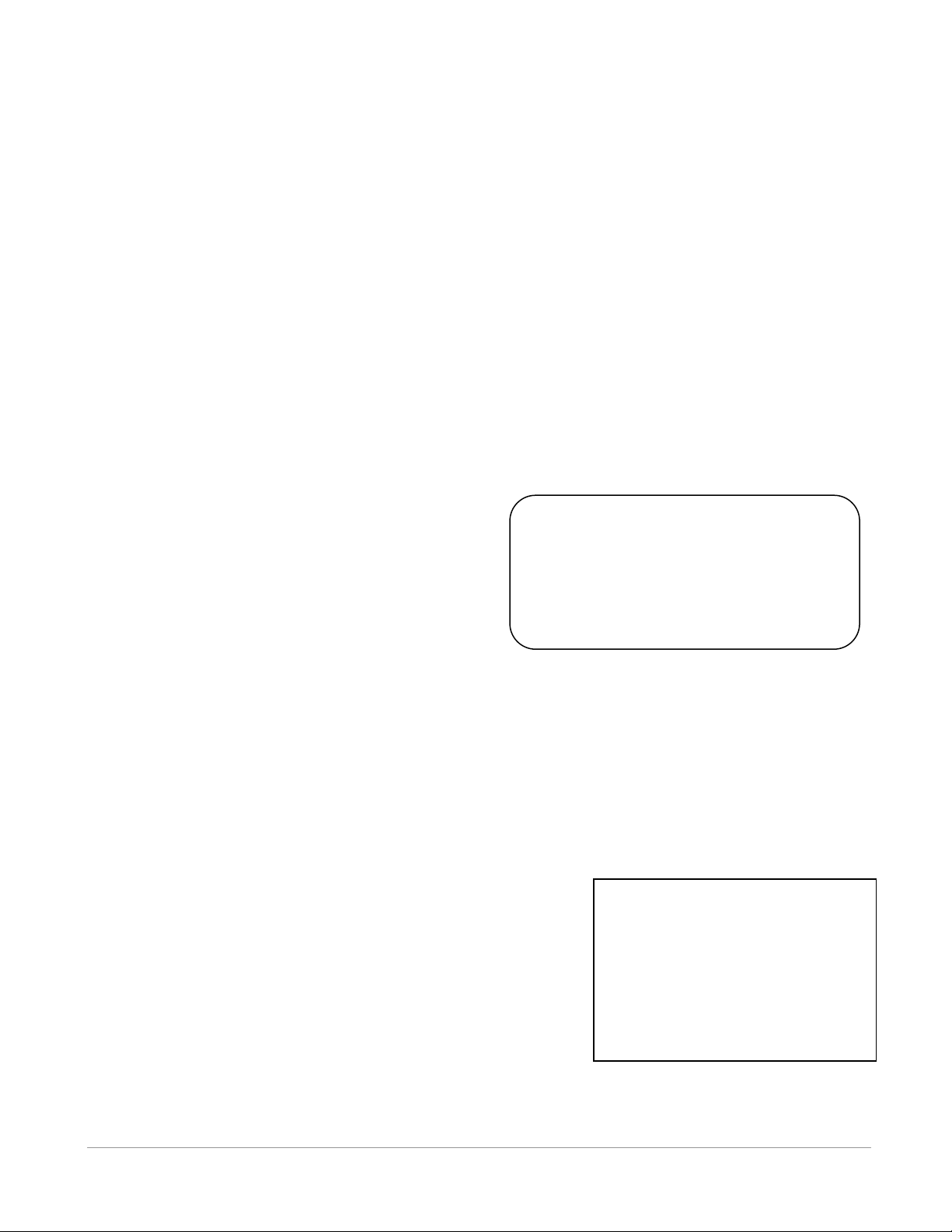
1. Select Monitor by pressing the left selection button. A screen on the VR100 will appear similar to the
sample below.
2. Press the channel number on the keypad to select the channel to be monitored.
3. Use the left selection button to select the desired level of Detection Parameter (see section 4.2). The
sample below has been set to Near. This setting is made on a per-channel basis so a channel must be
selected before this step can be performed.
4. Verify that the frequency shown is the desired frequency. If it isn’t, then the channel setup must be
edited (see section 4.3.1.2).
5. Deploy the directional hydrophone.
6. Use the audio output from either the speaker or
the headphones to listen for the deployed pinger.
You may need to rotate the hydrophone.
7. Ensure the receiver is in manual gain mode and
adjust the gain so that the pings are strong but not
saturating the receiver. Use the signal strength
meter as a guide (signal strength varies from 0 to
105 dB).
8. Watch the second line for the tag’s ping period (in milliseconds). The “P” indicates that the received
ping was from a continuous pinger. The time in seconds since the last ping was received is shown in
the top left corner. If the length of time is very large, the display will show 999 to indicate there
haven’t been any recent detections.
9. Slowly rotate the hydrophone rod in one direction. If the signal gets louder and stronger (the signal
strength level and bar graph increase) then continue to rotate the hydrophone in that direction. If the
signal gets softer and decreases, then reverse the rotation. When the signal is its strongest, the
hydrophone is pointing in the direction of the tag.
10. Move in the direction the hydrophone is pointing and watch/listen to the signal strength. If the signal
strength decreases, repeat step 10 until it increases again.
11. If necessary, adjust the gain so that the pings are strong but not
saturating the receiver.
Note: The gain setting is not critical and in most circumstances
satisfactory performance can be achieved without frequent gain
changes.
12. Continue this process of following the signal strength and
adjusting the gain until the signal strength is strong in all
directions (rotating the hydrophone doesn’t change the signal
strength). The tag is below the hydrophone.
VEMCO – VR100 Receiver Operating Manual – Page 11
Page 12

LT: 26 09:32:01
A69-1303 35dB ▊▊▏
# 154
Norm CH1 M18 Mute
2.2.5 Manually tracking a coded tag
After a channel in the VR100 has been setup to detect the coded pinger (see section 4.3.1.2.2) and the
pinger has been deployed, use the steps below to use the VR100 to track the pinger.
Tracking a tagged marine animal requires a directional hydrophone. The VR100 receiver is compatible
with the VH110 directional hydrophone. The directional hydrophone must be mounted on the end of a pole
so it can be rotated. It’s also helpful to mark which section of pole is facing in the same direction as the
black section of the hydrophone. This black section is the signal sensitive section of the hydrophone.
Tracking a coded tag is more difficult than tracking a continuous tag because coded tags transmit in ping
trains. A ping train is a burst of pings lasting 2-3 seconds followed with a delay that can be more than a
minute long (the delay length is determined by the customer at the time the tag is ordered). There is often
more than one tag in an area so you must determine which tag you’re tracking based on its ID number.
From the Main menu:
1. Select Monitor by pressing the left selection button. A screen on the VR100 will appear similar to the
sample below.
2. Press the channel number on the keypad to select the channel to be monitored.
3. Use the left selection button to select the desired level of Detection Parameter (sere section 4.2). The
sample below has been set to Norm.
4. Verify that the frequency shown is the desired
frequency. If it isn’t, then the channel setup must be
edited (see section 4.3.1.2).
5. Deploy the omni-directional VH165 hydrophone
and listen for coded tags in the area. Make note of
the code numbers and code spaces that are identified
and displayed in the second and third lines on the
screen. In the adjacent sample screen, the tag with
codespace A69-1303 and ID number 154 was
identified.
6. Remove the omni-directional hydrophone from the water and deploy the directional hydrophone.
7. Use the audio output from either the speaker or the headphones to listen for the deployed pinger.
8. Ensure the receiver is in manual gain mode and adjust the gain so that the pings are strong but not
saturating the receiver. Use the signal strength meter as a guide (signal strength varies from 0 to 105
dB).
9. The length of time since the last ping was received is shown in the top left corner. If the length of time
is very large, the display will show 999 to indicate there haven’t been any recent detections.
10. Slowly rotate the hydrophone rod in one direction. If the signal gets louder and stronger (the signal
strength level and bar graph increase) then continue to rotate the hydrophone in that direction. If the
signal gets softer and decreases, then reverse the rotation. When the signal is its strongest, the
hydrophone is pointing in the direction of the tag.
11. Move in the direction the hydrophone is pointing and watch/listen to the signal strength. If the signal
strength decreases, repeat step 11 until it increases again.
12. If necessary, adjust the gain so that the pings are strong but not saturating the receiver.
13. Continue this process of following the signal strength and adjusting the gain until the signal strength is
strong in all directions (rotating the hydrophone doesn’t change the signal strength). The tag is below
the hydrophone.
VEMCO – VR100 Receiver Operating Manual – Page 12
Page 13

NOTE: If the animal is operating in deeper water, then adjust the angle of the directional hydrophone so
it’s pointing downward as you get closer to the tag. If you don’t adjust the angle, you might miss
the animal because the hydrophone is looking at the surface of the water instead into its depth.
2.2.6 Enter slope and intercept for a continuous one-sensor transmitter
The tag’s information that must be entered in the VR100 is found in the Transmitter Specification manual
shipped with the tags. See section 4.3.4 for more details.
From the Main menu:
1. Select Config (right selection button).
2. Press “4” on the keypad.
3. Press “2” on the keypad.
4. If a list of serial numbers appears, press the left selection button to select “New”. Otherwise, go to
Step 5.
5. Enter the serial number of the tag and press “Next”.
6. Enter the tag’s operating frequency.
7. Enter the tag’s slope value.
8. Enter the tag’s intercept value.
9. Select the data type, either temperature or depth.
10. Enter the Minimum Period value.
11. Enter the Maximum Period value.
12. Press the right selection button to “Accept” this tag.
13. If more tags are to be entered, repeat steps 3 to 12.
14. Press the Menu button until the Main screen appears.
2.2.7 Enter slope and intercept for a continuous two-sensor transmitter
The tag’s information that must be entered in the VR100 is found in the Transmitter Specification manual
shipped with the tags. See section 4.3.4 for more details.
From the Main menu:
1. Select Config (right selection button).
2. Press “4” on the keypad.
3. Press “3” on the keypad.
4. If a list of serial numbers appears, press the left selection button to select “New”. Otherwise, go to
Step 5.
5. Enter the serial number of the tag and press “Next”.
6. Enter the tag’s operating frequency.
7. Enter the tag’s sync value (1150 is the default value).
8. Enter the tag’s first slope value.
9. Enter the tag’s first intercept value.
10. Select the data type for the first sensor (usually temperature).
11. Enter the tag’s second slope value.
12. Enter the tag’s second intercept value.
13. Select the data type for the second sensor (usually depth).
VEMCO – VR100 Receiver Operating Manual – Page 13
Page 14
NOTE: For coded two-sensor tags, two separate sensor tag entries are required – one for each tag ID
(sensor). Since the VR100 does not allow duplicate serial numbers in the sensor database, the serial
number for the second sensor entry must be different than the first sensor entry. We recommend that
you use the serial number provided on the specification sheet for the first sensor entry, and the same
serial number with a prefix for the second sensor entry. For example, using “20” as the prefix:
Sensor 1 SN: 1034857
Sensor 2 SN: 201034857
14. Enter the Minimum Period value.
15. Enter the Maximum Period value.
16. Press the right selection button to “Accept” this tag.
17. If more tags are to be entered, repeat steps 3 to 16.
18. Press the Menu button until the Main screen appears.
2.2.8 Enter slope and intercept for a coded sensor tag
The tag’s information that must be entered in the VR100 is found in the Transmitter Specification manual
shipped with the tags. See section 4.3.4.1 for more details.
From the Main menu:
1. Select Config (right selection button).
2. Press “4” on the keypad.
3. Press “1” on the keypad.
4. If a list of serial numbers appears, press the left selection button to select “New”. Otherwise, go to
Step 5.
5. Enter the serial number of the tag and press “Next”.
6. Enter the tag’s operating frequency.
7. Select the code space from the list provided by pressing the up or down arrow until the correct code
space name is shown on the display.
8. Enter the coded tag ID number.
9. Enter the tag’s slope value.
10. Enter the tag’s intercept value.
11. Select the data type, temperature, depth or acceleration.
12. Press the right selection button to “Accept” this tag.
13. If more tags are to be entered, repeat steps 3 to 13.
14. Press the Menu button until the Main screen appears.
VEMCO – VR100 Receiver Operating Manual – Page 14
Page 15
IMPORTANT
When the VR100 memory
is full, it must be erased
before more data can be
stored. Use the VR100HS
software to copy data to a
computer before erasing
the VR100’s memory.
Event Log
Event Count: 42500
Use: 50 % ▊▊▊
Erase
Press right selection
button to erase memory
Amount of
memory used
NOTE: Ensure that the GPS receiver has a position fix before manually logging GPS readings. If the
GPS receiver is not “locked” when the LOG GPS button is pressed, the request will be queued until a
GPS position fix is obtained.
2.2.9 Take a GPS reading
A GPS reading is automatically stored in the VR100’s memory with each detection if the GPS receiver is
“locked” (see section 5.1). Manual GPS readings can be taken while in the Monitor screen (see section 4.2)
and stored to memory by pressing the LOG GPS button on the front panel of the receiver (see section
3.1.3).
2.2.10 View Used Memory Level
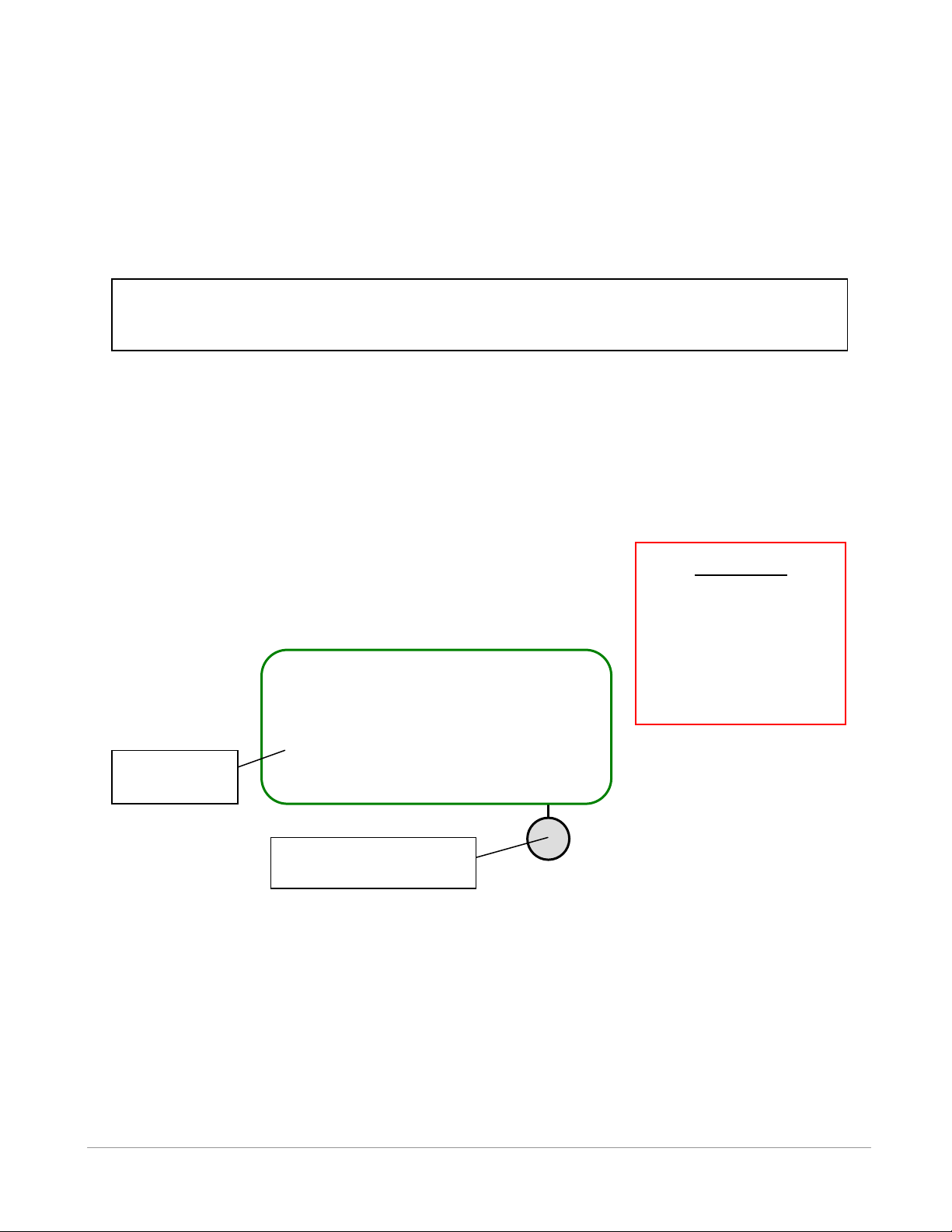
The Use line in the Event Log screen shows the percentage of log memory used in the VR100 receiver,
both numerically and graphically. When 100 % of the log memory is full, the memory must be erased
before more events can be logged; old data are not deleted, but new data will not be stored until the
memory is erased. To prevent loss of data, upload the VR100’s memory to your PC before erasing
the memory.
To erase memory using the VR100, from the Main menu on the VR100:
1. Select Config (right selection button).
2. Press “5” on the keypad.
VEMCO – VR100 Receiver Operating Manual – Page 15
Page 16
IMPORTANT: The signal strength reading is a relative measure of the voltage level present at the
receiver input (0dB = minimum measureable voltage, 105dB = full scale voltage). It is strictly a
relative measure of signal strength and cannot be used to measure the output power of a transmitter
in terms of dB re 1uPa @ 1m.
2.2.11 Clear VR100 Memory
When 100 % of the log memory is full, the memory must be erased before more events can be logged. The
memory is erased from either the Event Log screen (described below) or from within the PC software, but
the memory should only be erased after the log has been copied to a computer (see the software manual
for details).
To erase memory using the VR100, from the Main menu on the VR100:
1. Select Config (right selection button).
2. Press “5” on the keypad.
3. Press the right selection button to erase the data. It’s strongly recommended that data be loaded to a
computer using the VR100HS software before the memory is erased.
4. Confirm the erasure of the data by pressing the button identified in the confirmation window.
Erasing the event log will only erase the events that have occurred to the VR100 receiver and not the
channel settings or the sensor tag information.
2.2.12 Using Signal Strength and Gain when tracking
When tracking a tag using the VR100 and a directional hydrophone (the VH110 for example), the signal
strength will increase as the hydrophone approaches the tag. The gain must be set to manual (“M” appears
in the Monitor screen – see section 4.2) during this procedure.
When the signal strength bar graph is near full scale, the manual gain should be reduced so meter
variations will indicate transmitter direction as the hydrophone is turned. If the signal level indicator is at
the bottom of the scale, the gain should be increased to detect meter variations.
VEMCO – VR100 Receiver Operating Manual – Page 16
Page 17
WARNING
Never remove the receiver’s front panel
from the case or the internal components
could be irrevocably damaged. There are
no user-serviceable parts inside.
Opening the unit will void your warranty.
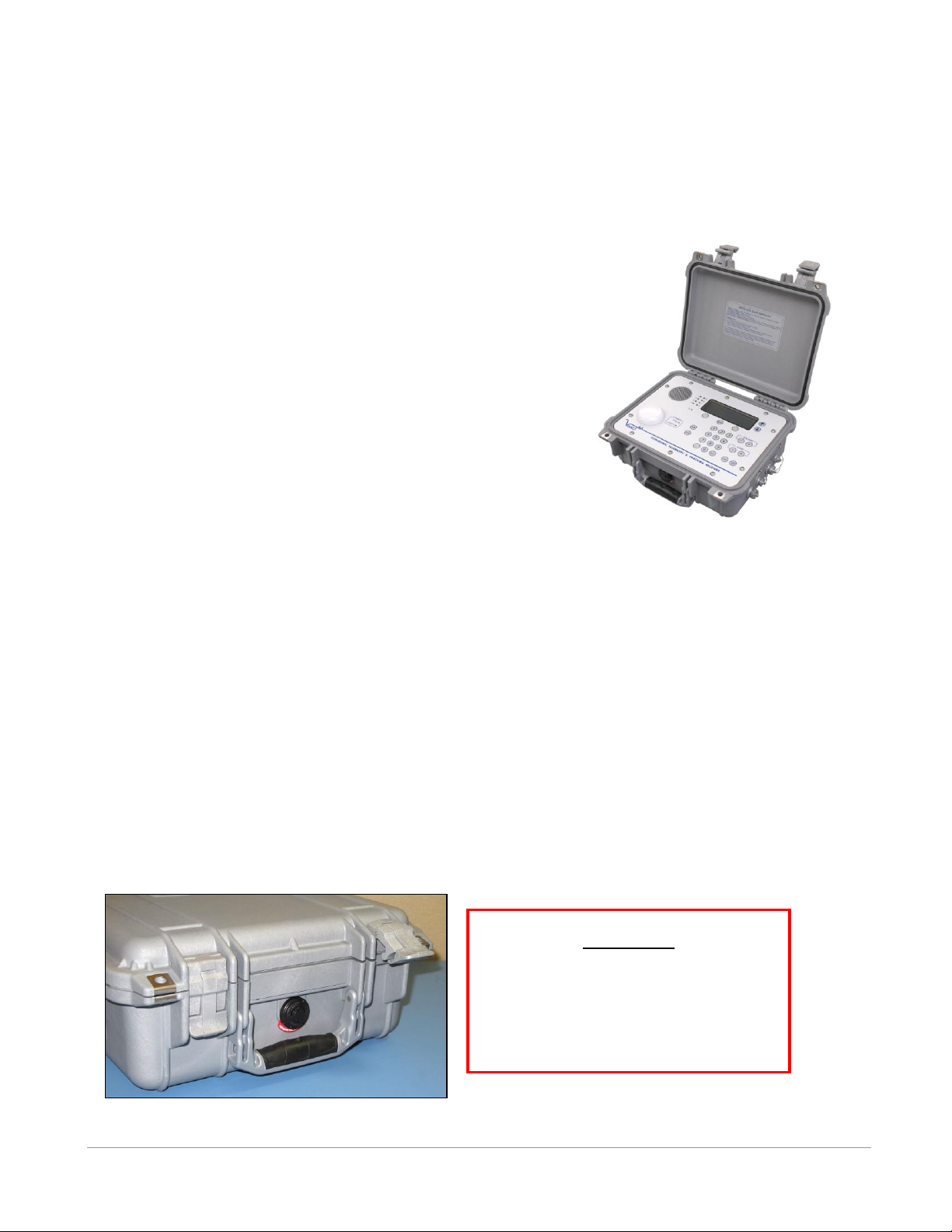
Latches and pressure relief vent on VR100 receiver.
3 HARDWARE
3.1 CASE
The VR100 receiver is housed in a strong, sealed, splash-resistant
case, as shown in the photo here. The cover of the case must be
opened to access the receiver’s front panel (see section 3.1.3) with
the LCD display and the soft-touch controls. A gel cell battery is
housed in the case to supply stand-alone power to the receiver.
There are connectors on the right side of the case for the
hydrophone, the USB computer connection, the battery charger, and
audio headphones (see section 3.2.2). The case should always be
latched closed while the receiver is being transported.
The VR100 receiver can be used during a light rain as long as the
hydrophone is connected to the case and the remaining three
protective caps are in place (see section 3.1.2.2). Water should be
wiped from the front panel with a dry cloth before it accumulates.
The USB cable, battery charger, and headphones should only be
used when the receiver is safe from exposure to water.
The case has a pressure relief vent to allow any pressure build-up in the case to release before the case is
opened. This vent is located between the latches on the side of the case, as seen in the photo below. A
manufacture’s tag is attached to the vent and should not be removed. Removing the tag may damage the
vent.
3.1.1 Opening Case
To open the VR100 case, follow the steps below.
1. Place the case on a stable, flat, horizontal surface so the VR100 label is on the top (facing up).
2. Lift one of the latches (see photo below) until it is horizontal. The latch will separate slightly as it is
moved, as the right latch shows in the photo below.
3. Lift the other latch until it is horizontal. Both latches can be raised together.
4. Lift the lid of the case so it is in the position shown in the photo above.
VEMCO – VR100 Receiver Operating Manual – Page 17
Page 18
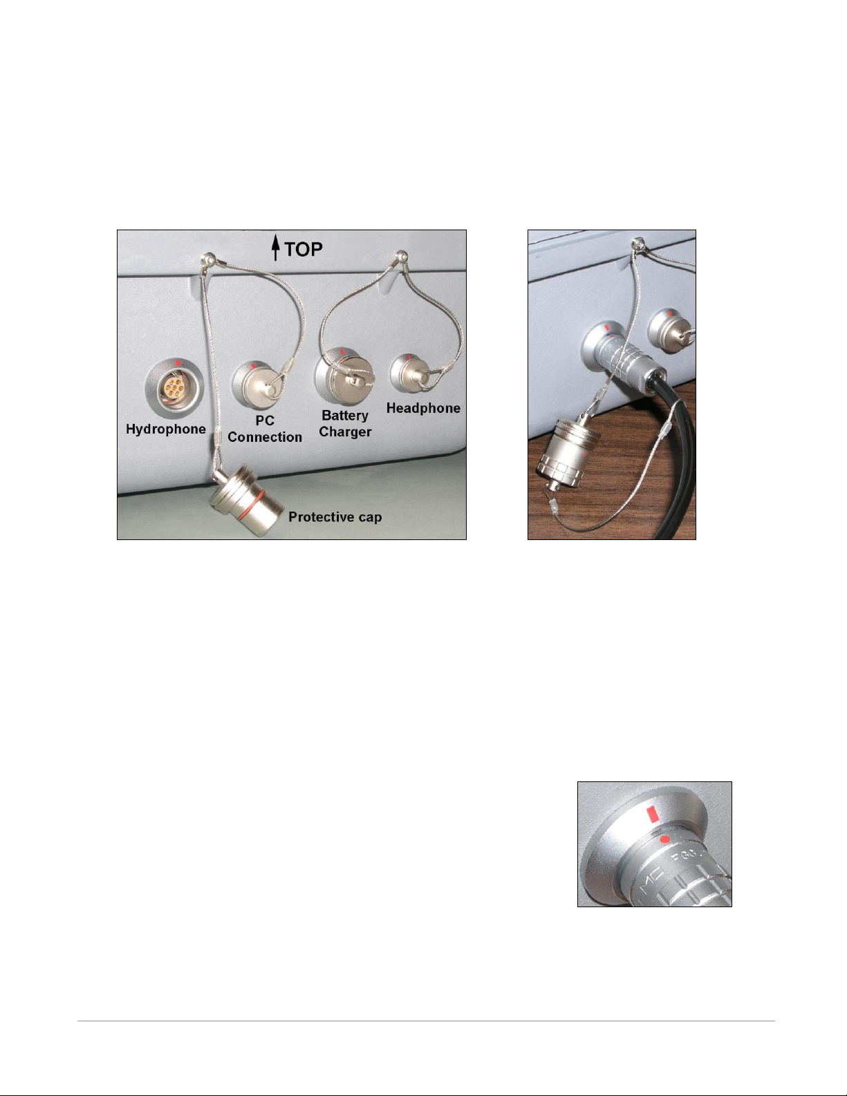
Connector halves properly
lined up.
Protective caps joined when
not in use.
Connectors and protective caps.
3.1.2 Connectors
There are four bulkhead connectors on the right side of the VR100 case for connecting the different
components of the VR100 system to the receiver (see photo below, on the left). The connectors are, from
left to right: hydrophone, PC connection, battery charger, and headphone.
Each bulkhead connector has a cap to protect the connector from contact with water. The protective cap
from the receiver’s hydrophone connector should be joined to the protective cap attached to the
hydrophone cable when the caps are not in use, as shown in the photo above and on the right.
WARNING: DO NOT get water in the connectors that attach to the VR100 receiver, such as the PC
connection cable or the headphone cable. Water will enter the connector to damage the cabling and
potentially damage the receiver.
3.1.2.1 Using connectors
The red dot on the end of the connector must line up with the red line on
the VR100’s connector, as shown in the photo on the right. The
connectors have unique grooves to prevent the wrong connector halves
from being placed together.
VEMCO – VR100 Receiver Operating Manual – Page 18
Page 19
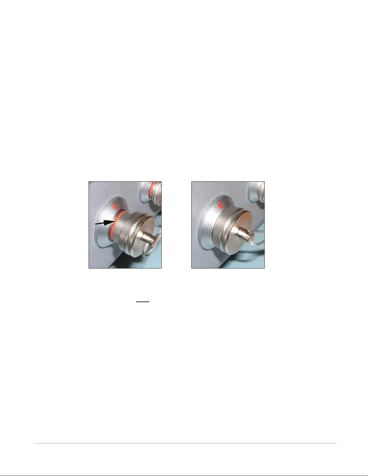
Connector protective cap – not
properly inserted in connector.
Connector protective cap –
properly inserted in connector.
3.1.2.2 Using protective caps
The connector’s protective cap is used to prevent water from entering the connector and damaging the
connector and possibly the receiver. With the cap properly in place, the VR100 is extremely splashresistant.
To properly install a connector protective cap:
1. Select the proper cap. The caps are in two sizes, small and large. The small caps are for the PC
communication connector and the headphone connector. The large caps are for the hydrophones and
the battery charger.
2. Check that the O-ring on the cap is clean and undamaged. The O-ring is identified by the arrow in the
photo below and on the left.
3. Insert the cap into the connector on the side of the VR100 case.
4. Press the cap into the connector until the lip of the cap is in contact with the connector ring on the
VR100 case. This is shown in the photo below and on the right.
WARNING: The protective caps must be in place on the receiver when a cable isn’t connected to the
bulkhead connectors. Water that comes in contact with exposed bulkhead connectors can damage
the receiver.
VEMCO – VR100 Receiver Operating Manual – Page 19
Page 20
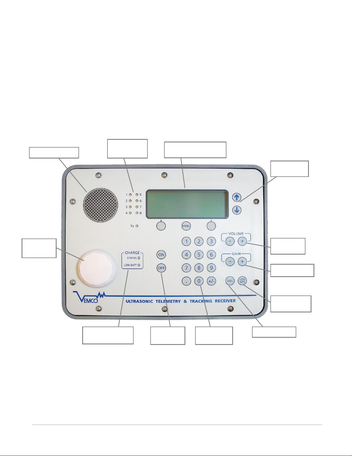
A) Audio speaker
B) Detection
indicators
C) LCD screen and
three related buttons
D) Up/Down
buttons
E) Volume
control
F) Gain control
G) LOG GPS
button
H) AGC button
I) Numeric
keypad
J) Power
buttons
K) Battery charge
indicators
L) GPS
antenna
3.1.3 VR100 Front panel
The VR100 receiver’s front panel allows the VR100 to be configured and allows deployed tags to be
monitored. The panel uses soft press keys for all its data entry and controls, increasing the receiver’s
ability to operate in a moist environment. The soft buttons are easy to wipe clean but still give the user a
“click” that can be both heard and felt to verify the button has been pressed. The different aspects of the
VR100 front panel are identified in the photo below with brief explanations in the following sections.
WARNING: Never remove the VR100’s front panel. There are no user-serviceable parts inside.
VEMCO – VR100 Receiver Operating Manual – Page 20
Page 21

3.1.3.1 VR100 Front panel Explanations
The explanations given below correspond with the photo of the VR100 face plate.
A) Audio speaker:
The speaker allows the pings received from acoustic tags on the active channel to be heard when the
VR100 is in Monitor mode (see section 4.2); when the VR100 is not in monitor mode, the audio is
muted. The sound can be muted within the Monitor screen (see section 4.2) and can be adjusted with
the volume buttons.
B) Detection indicators:
A detection indicator flashes a green light each time a ping is detected by the receiver. Each detection
indicator is numbered and corresponds to a receiver channel (see section 4.3.1). When a ping is
received on a channel, the corresponding detection indicator light will flash. For example, if indicator
2 flashes then we know that channel 2 received a ping.
NOTE: More than one detection indicator can flash at the same time if more than one channel is
active (turned on) and pings are simultaneously received on those channels. For example, if channels
1 through 3 are set up for different continuous tag types on 60 kHz then all three detection indicators
will flash when a ping is received on 60 kHz.
C) LCD screen and three related buttons:
The LCD screen is used to monitor tags and to configure the VR100. The use of the screen and the
three buttons immediately below it is explained in section 4.
D) Up/Down buttons:
The up and down buttons are used to move a cursor through a list displayed on the LCD screen (see
section 4.3).
E) Volume control:
The volume control will increase or decrease the volume of the audio signal heard from either the
speaker or the headphones (see section 3.2.3). The button marked with a plus symbol (+) increases the
volume and the button with the negative symbol (-) decreases the volume. The buttons can be held
down or pressed repeatedly for a larger change in volume. The Monitor screen (see section 4.2)
displays the volume level as “VOLXX” where the XX represents a numeric volume level.
F) Gain Control:
The gain control buttons will increase or decrease the gain level in steps of six decibels (6 dB). The
button marked with a plus symbol (+) increases the gain by 6 dB and the button with the negative
symbol (-) decreases the gain by 6 dB.
G) LOG GPS button:
The LOG GPS button is used for manual GPS recordings. Pressing the LOG GPS button while in the
Monitor screen will cause the next valid GPS position to be recorded to the VR100’s memory. If the
GPS is locked at the time the button is pressed, then the position will be recorded within 1 second. If
the GPS is not locked, then it could be much longer before the position is recoded. See section 5.1.1
for more information of GPS. NOTE: Manual GPS readings can only be taken while in the Monitor
screen (see section 4.2).
VEMCO – VR100 Receiver Operating Manual – Page 21
Page 22

H) AGC button:
The AGC (Automatic Gain Control) button toggles the gain level between automatic (AGC) and
manual. Use of the button is explained in section 4.2. AGC is explained in the Glossary (section 5.3).
I) Numeric keypad:
The numeric keypad is used to enter numbers while configuring the receiver (see section 4.3) or to
select specific channels while monitoring tags (see section 4.2).
J) Power buttons:
The power buttons turn on and off the VR100 receiver. The ON button will turn the VR100 on and
display the welcome screens while the receiver is booting up. The OFF button will begin the VR100’s
shut-down procedure.
K) Battery charge indicators:
The battery charge indicators show the status of the battery charging process and indicate when the
battery charge is low. More details about charging the battery are found in section 3.3.1.
L) GPS antenna:
The GPS antenna is contained inside the plastic “puck” for protection and attached to the front panel.
The GPS antenna is able to receive the GPS signals when the VR100 is outdoors, even with the case
lid closed. More information about the GPS is located in section 5.1.1.
3.2 ATTACHMENTS
3.2.1 Hydrophone
The hydrophone can be compared to a human ear where the VR100 is the human brain. Our ear hears the
noises around us and transfers them to the brain where the noises are analyzed and identified. The
hydrophone hears pings from acoustic tags in the water, as well as other noises in the environment such as
current flow, marine animals, and ship engines. It transfers all these noises to the VR100 receiver where
the pings are separated from the other noises using electronic filters. The pings are then identified and
recorded. The VR100 can’t function without a hydrophone.
The VR100 can be used with an omni-directional hydrophone (VH165 or VH180) or a directional
hydrophone (VH110). The hydrophone is connected to the VR100 through the bulkhead connector on the
side of the receiver (see section 3.1.2). Refer to the table on the following page to identify the correct
hydrophone for a particular application.
WARNING: DO NOT connect a hydrophone to the VR100 while the receiver is powered.
The protective cap attached to the hydrophone cable should be on the cable’s connector when the
hydrophone is not connected to the VR100 to prevent water from entering the hydrophone’s connector.
Water in the connector may enter the cabling and cause damage.
VEMCO – VR100 Receiver Operating Manual – Page 22
Page 23
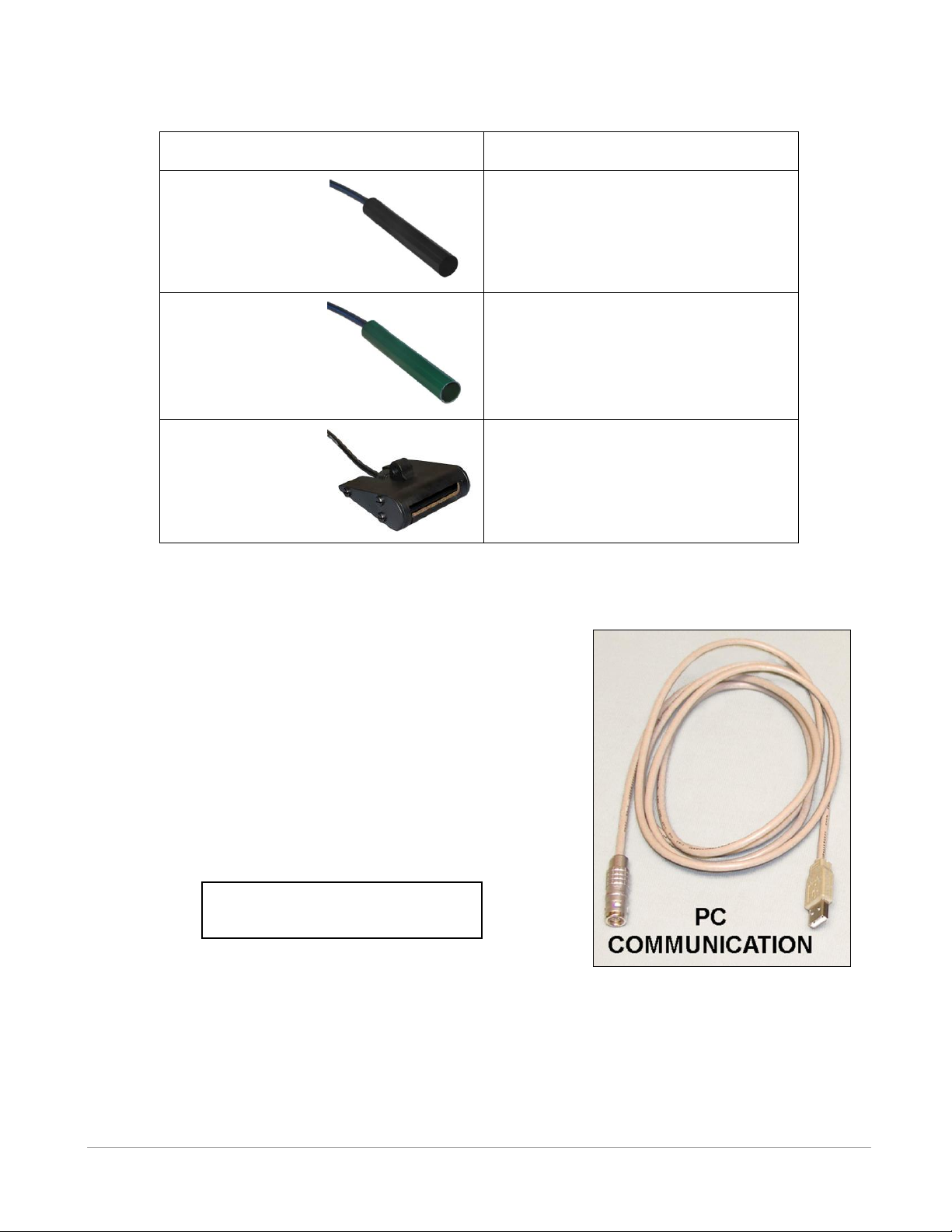
Hydrophone
Recommended Usage
VH165
Omni-directional
50-85 kHz
Black Housing
Monitoring and testing 69 kHz coded and
50 – 85 kHz continuous transmitters.
VH180
Omni-directional
180 kHz
Green Housing
Monitoring and testing 180 kHz coded
transmitters.
VH110
Directional
50-85 kHz
Black Transducer
Locating and tracking 69 kHz coded and
50 – 85 kHz continuous transmitters.
Please read the USB warning at
the front of the manual
3.2.2 USB Cable
The VR100 receiver is connected to a computer through an adapted
USB cable, shown in the photo here. The marine grade connector,
shown on the left in the photo, is connected to the second connector
from the left on the VR100 case (see section 3.1.2) and the USB
connector, shown on the right in the photo, is connected to a USB
port on the computer.
WARNING: Keep the USB cable dry when it is not in use. Water
could enter the connectors and damage the cable, which
could potentially damage the VR100 receiver.
VEMCO – VR100 Receiver Operating Manual – Page 23
Page 24

Warning
Permanent hearing loss may occur if the headphones or
internal speaker is used at high volume. Set the volume to a
safe level. Avoid turning up the volume to block out noisy
surroundings.
3.2.3 Headphones
A marine grade headphone jack is located on the side of the VR100 case (see section 3.1.2). A pair of
headphones with a matching jack is supplied by VEMCO.
WARNING: Do not allow the headphone connector to come in contact with water. Water could enter the
back of the connector and damage the headphone cable, which could potentially damage the
VR100 receiver.
VEMCO – VR100 Receiver Operating Manual – Page 24
Page 25
The VR100
battery fully
charges in
14 hours at
room
temperature.
AC Battery Charger
DC Battery Charger
3.3 MAINTENANCE
3.3.1 Charging Battery
When the internal gel-cell battery is fully charged, it will power the VR100 receiver for approximately 12
hours with the backlight off and under normal operating conditions. Operating time with the backlight on
is shorter. The VR100 can also be powered while the battery is being charged, allowing the receiver to
continue to operate during the charging process.
Follow the steps listed below to charge the VR100’s battery:
1. Place the receiver away from direct heat sources (including direct
sunlight) and in a horizontal position so the front panel is facing up.
It is best to charge the VR100 at room temperature.
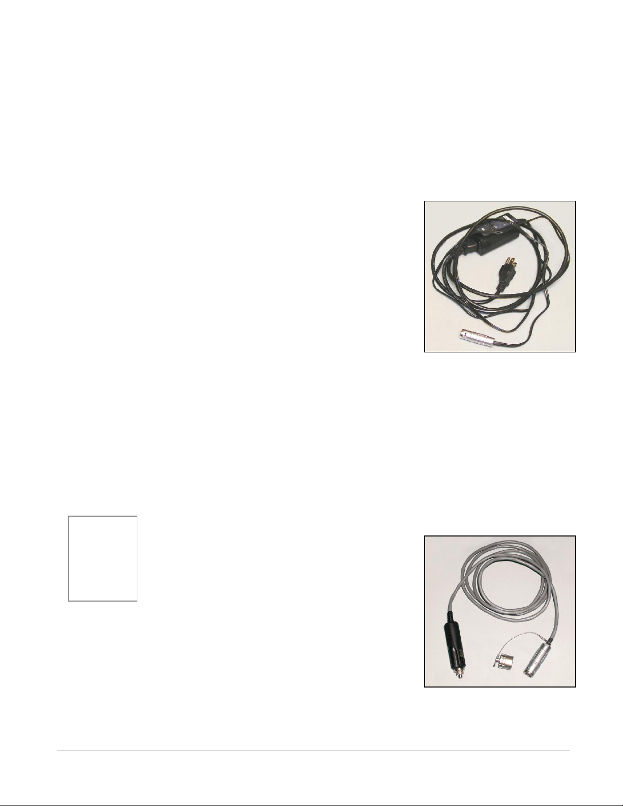
2. Select a battery charger based on the power supply type, either AC
or DC. Both chargers are pictured on this page. The AC charger
may require an adapter plug.
3. Plug the metal connector on the supplied battery charger into the
Power connector on the side of the VR100 case (see section 3.1.2).
The connector on the charger cable will only fit the Power
connector on the receiver and only in the correct orientation.
4. Plug the other end of the AC battery charger into a 50/60 Hz, 100 to
240V AC power source, or the DC battery charger into 12VDC power source.
The VR100 receiver is equipped with internal sensors that determine its position and internal temperature.
These sensors prevent the charging process if the receiver is positioned at a steep angle or upside down, or
if the internal temperature of the receiver is excessive. If the VR100 is tilted, the STATUS and LOW
BATT lights (also called LEDs) on the front panel will both flash and charging will not occur. To charge
the battery when both lights are flashing, unplug the VR100 charger and reposition the VR100 with the
front panel facing up before plugging the charger back into the power supply (see section 3.3.1.1). If the
internal temperature exceeds a safe limit, battery charging will be disabled until the receiver has cooled,
then it will automatically resume.
The VR100 battery charges in two stages, Fast and Float. The Fast Charge mode quickly
charges the battery most of the way, and the Float Charge
mode slowly charges it the rest of the way. The battery can
be left in Float Charge mode for an extended period without
damaging the battery. When the "STATUS" light is on
steady, the unit is in Fast Charge mode. When the light
begins flashing, the unit is mostly charged and is in Float
Charge mode. The unit can be used as soon as it enters Float Charge mode,
but it will not necessarily last the entire 12 hour battery life. To achieve the
12 hour battery life, the unit should be charged for 14 hours or more at room
temperature. At high ambient temperatures, charging may take longer
because the VR100 turns the charger off and on to control the internal
temperature.
VEMCO – VR100 Receiver Operating Manual – Page 25
Page 26
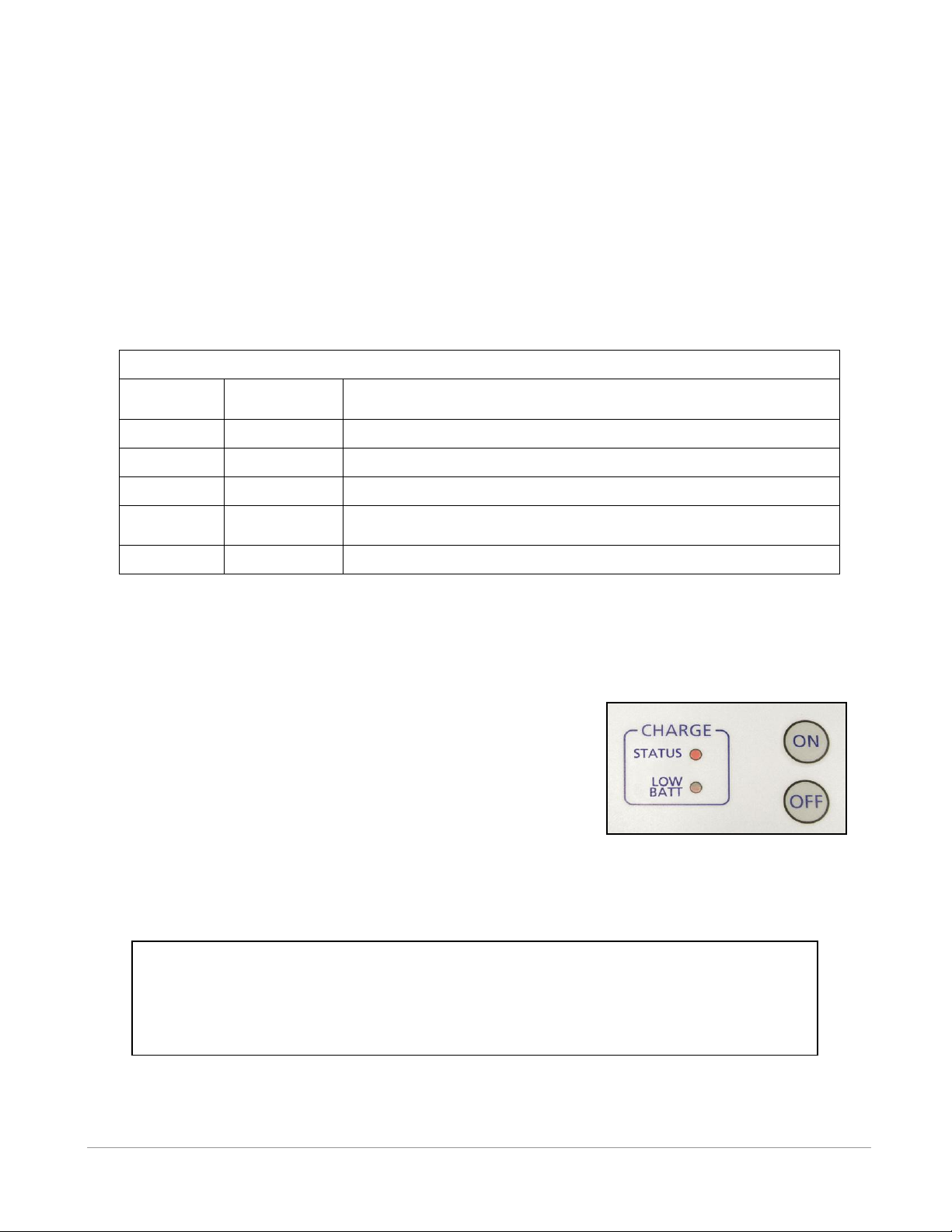
Table 3.3-1: Charge Indicator Lights.
STATUS
light
LOW BATT
light
Description
Flashing
Off
Battery is mostly charged and is in Float Charge mode
On Steady
Off
Battery is charging.
Off
Flashing
Battery is nearing discharge.
Off
On Steady
Battery is discharged and the VR100 is about to shut shown.
External power is required.
Flashing
Flashing
Tilt or Power System Fault has occurred – see paragraph below.
The VR100 can be safely used in a vertical position (front panel is perpendicular to the floor)
with an external power source connected but the battery WILL NOT CHARGE under this
condition. The “STATUS” and “LOW BATT” lights will both flash as long as the unit is vertical
and an external power source is connected. In this situation, the unit is being powered from the
external supply, and thus can be used indefinitely, regardless of the level of battery charge.
NOTE: The VR100 battery can be left in Float Charge mode for an extended period of time without
causing damage to the battery, but the receiver’s front panel must be facing up. A sensor is
included in the VR100 that prevents the receiver from being charged while the receiver is at a
steep angle or upside down.
3.3.1.1 Charge Indicator Lights
The “Charge” indicator lights (also called LED – “Light Emitting Diode”) on the VR100’s front panel are
the “STATUS” light and the “LOW BATT” light. These lights are to the left of the ON and OFF buttons
(see photo below). The meaning of these lights is explained in Table 3.3-1.
NOTE: The battery can be left in Float Charge mode for an extended period without damaging the battery.
If a Tilt or Power System Fault occurs, follow the steps below to clear the fault and resume normal
battery charging operation.
1. Ensure that the front panel of the VR100 is facing up.
2. Ensure that a proper power supply is connected to the VR100.
If the voltage is too high or too low, a Power System Fault
results.
3. Place the VR100 away from direct sources of heat (including
direct sunlight) and allow it to cool.
4. Unplug the external power supply and wait for the lights to
stop flashing
When these conditions have been met, plug the external power supply into the VR100 again. If both lights
continue to flash, unplug everything from the VR100 case (power supply, hydrophone, USB cable, and
headphones) and call VEMCO support at +1-902-450-1700 or email to [email protected].
VEMCO – VR100 Receiver Operating Manual – Page 26
Page 27

3.3.1 Maximizing Battery Service Life
The VR100 is powered by a rechargeable lead-acid gel battery. It is normal for the performance of all
rechargeable batteries to diminish gradually over time and with use, but with proper care the VR100
battery should provide a useful service life of several years.
The conditions that cause the most severe degradation of a battery are over-discharging it, and extreme
temperatures (whether operating or not). To protect against these, the VR100 will automatically shut itself
off if the battery is run down, and it manages its internal temperature by shutting down first the battery
charger then the entire receiver if necessary to keep the temperature below an acceptable limit.
To maximize the service life of your VR100 battery, follow these recommendations as much as possible:
Keep the battery fully charged and avoid completely discharging it. When you see the Low Battery
warning indicated on the LEDs, connect the charger. After each time you use the VR100, recharge
the battery even if it is not fully depleted. A series of partial discharges is gentler on the battery
than a deep discharge.
If the VR100 shuts itself down due to a fully discharged battery, do not turn it back on until you
have connected the charger.
Store, charge, and operate the VR100 between 15 C and 25 C if possible. Storing the VR100 long
term at 35 C will actually reduce the battery’s service life by a factor of about ½.
Store the VR100 under clean, dry, non-condensing conditions.
3.3.2 Long-Term Storage
The VR100’s battery slowly discharges during storage and will become discharged during long-term
storage. Storage over one year is considered long-term storage. If the VR100 is to be stored long-term,
then protect the battery by following one of the suggestions listed below.
1. Store the VR100 with the charger plugged in to an external power supply; OR
2. Charge the VR100 overnight at least once a year.
Observe the recommendations under section 3.3.1 Maximizing Battery Service Life
VEMCO – VR100 Receiver Operating Manual – Page 27
Page 28
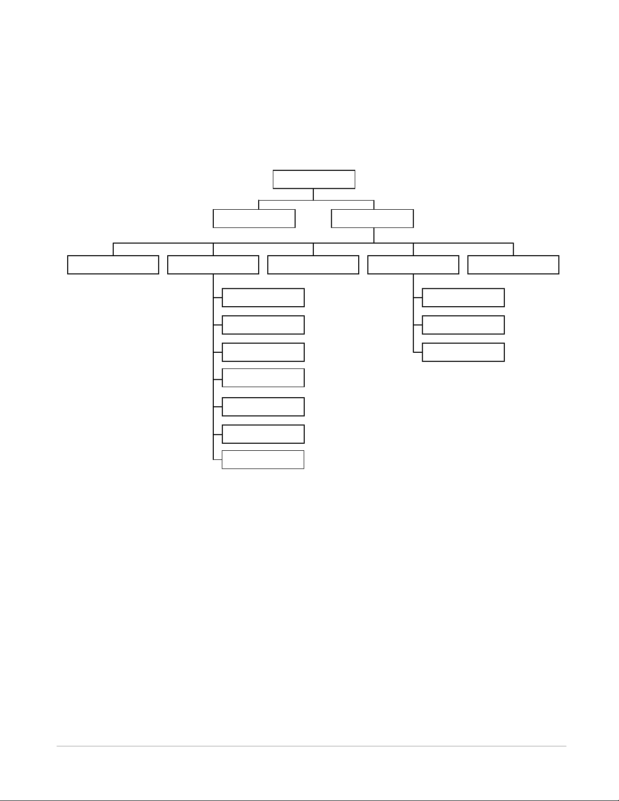
2. CONT. ONE
1. CODED
3. CONT. TWO
2. SYSTEM
3. CODE MAPS
4. SENSOR TAGS
5. LOG
1. CHANNEL
MAIN
MONITOR
CONFIG
2. CONTRAST
1. TIME
3. BACKLIGHT
5. UNITS
6. VERSION
7. RESET DEF
4. BATTERY
4 OPERATION
After the hardware is set-up as described in the Hardware section of this manual, the receiver is ready for
use. The VR100 receiver is menu-driven, beginning at the Main display. The menu options are mapped
out below and explained in detail in the sections to come.
When the VR100 is powered, the welcome screens appear while the receiver is booting up. After the boot
process is complete, the Main menu appears in the LCD screen. From the Main menu, there are two
selection options, Monitor and Configure (Config). Monitor is used to track and monitor acoustic tags. Its
features are described in the Monitor section (section 4.2). The Configure selection is used to configure
the VR100 receiver. This includes setting up tags, selecting code maps, turning channels on and off,
adjusting the contrast, turning on the backlight, and other features. The features are listed and explained in
the Configure section (see section 4.3).
NOTE: The “Monitor” option is only displayed in the Main menu screen when at least one channel has
been turned on. Setting up a channel and turning it on is explained in section 4.3.1.
VEMCO – VR100 Receiver Operating Manual – Page 28
Page 29
2012 10 17 13:45:09+
44.64100N 63.67090W
Sats: 7 SBAS
Monitor Config
E) Selection button
E) Selection button
G) GPS
Status lines
A) Date and time
B) Date/Time source
indicator
C)
Direction
Arrows
D) Action option
D) Action option
MENU
F) Menu button
4.1 MAIN MENU
The Main menu is the first display seen on the LCD screen after the receiver has booted up. It’s from this
point that the choice between monitoring tags and configuring the receiver is made.
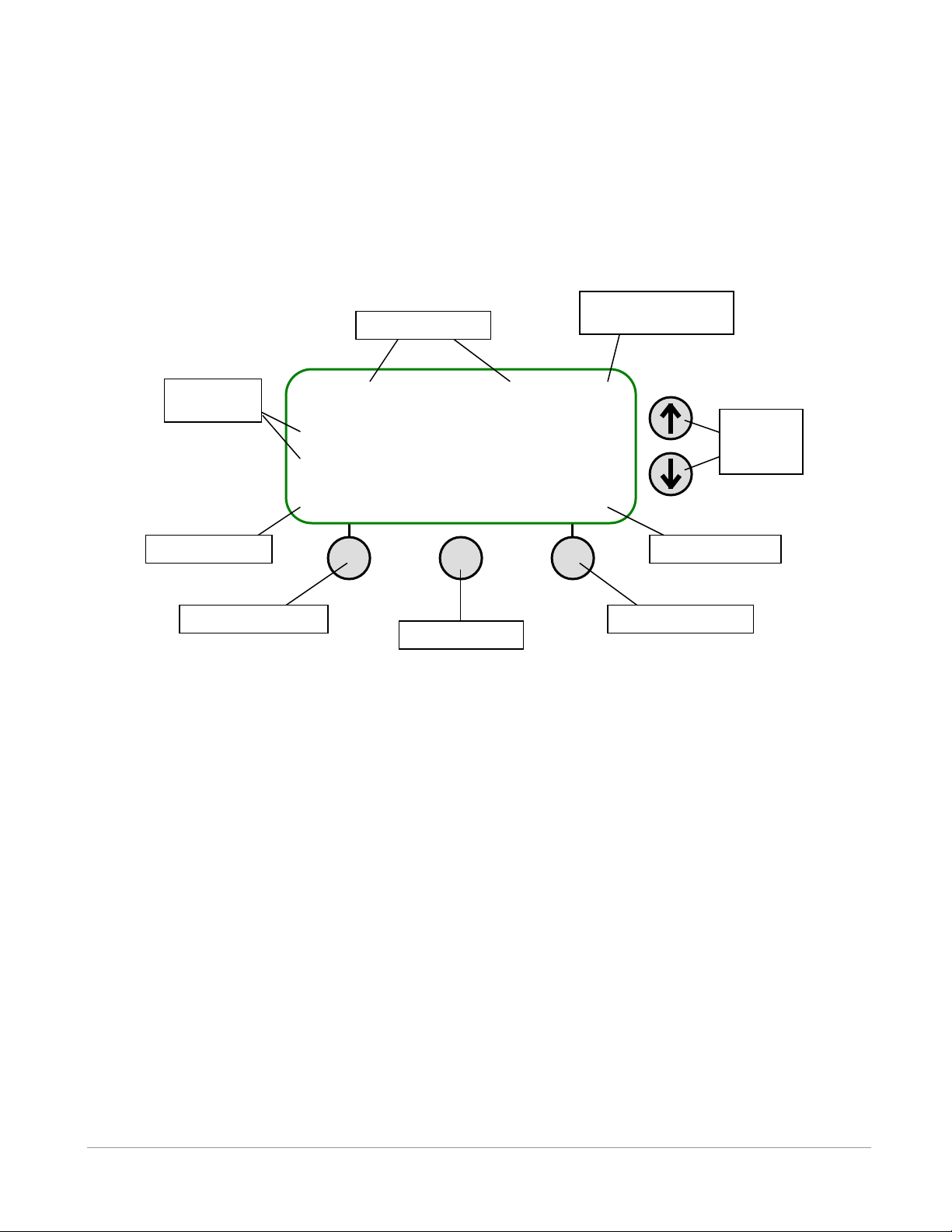
The LCD screen on the VR100 receiver has four lines for text, and each line may contain more than one
piece of information. The information found on the Main menu, and the buttons used with the screen, are
identified in the sketch and described below. These buttons will be used throughout the menu architecture.
4.1.1 Main Menu Explanations
The explanations given below correspond with the diagram of the Main menu above.
A) Date and time:
The date and time are displayed on the VR100’s screen in the format YYYY MM DD HH:MM:SS.
Both the date and time can be manually set to any moment on any day, but as soon as the GPS locks
the date and time will be corrected to the local time based on the Coordinated Universal Time (UTC)
and the offset entered in the VR100 by the user (see section 4.3.2.1).
B) Date/Time source indicator:
This symbol indicates if the date and time are synchronous with the GPS. A negative symbol (-)
indicates the date and time are not currently in sync. A positive symbol (+) indicates the date and time
are in sync with the GPS, which is Coordinated Universal Time (UTC). Section 5.3 has more
information on UTC.
VEMCO – VR100 Receiver Operating Manual – Page 29
Page 30

C) Direction arrows:
The direction arrows allow you to move through a list. If a single-head arrow, such as ↑ or ↓, is found
on the screen, then the list shown continues off the screen in the direction the arrow is pointing. Using
the arrow buttons will move the cursor through the list so the additional items can be seen.
The double-head arrow symbol (↕) on a line indicates that that particular line has a list of choices
associated with it. The list is viewed, one item at a time, by using the up or down arrow.
D) Action option:
Actions that can be performed are shown in one of these two locations, either the bottom left corner or
the bottom right corner of the screen. Common options are “Next” and “Select”. The action is
selected by pressing the soft selection button below the action word (labelled “E” in the diagram
above). A line on the front panel links the selection button with the action above it. If there is no text
in the action option location, then there is no action available.
E) Selection button:
Pressing a selection button will perform the action associated with the button. The action is displayed
in one of the Action option locations, labelled “D” in the diagram above. A line on the front panel
links the selection button with the action above it. The buttons are referred to as the left selection
button, which is on the left, and the right selection button, which is on the right.
F) Menu button:
The menu button moves up through the menu hierarchy. It may need to be pressed more than once to
get to the desired menu location. If “Next” or “Accept” are not displayed then the Menu button is used
to accept (save) the settings on the screen and move up the menu hierarchy. If “Next” or “Accept” are
displayed then pressing the Menu button will abandon the settings on the screen and move up the
menu hierarchy.
G) GPS status line 1:
The GPS location information is displayed on this line when the GPS is locked. If the GPS is not
locked then this line displays the GPS status. The different status messages are explained in the
Appendix (section 5.1.1).
GPS status line 2:
The number of satellites in view and SBAS indicator are shown on this line. Note that SBAS is
supported only on model VR100-200
VEMCO – VR100 Receiver Operating Manual – Page 30
Page 31
LT: 47 S3 07:23:11
A69-9002 50dB ▊▊▊
# 13643 0.3546 m/s2
Norm CH1 M12 Mute
J) Last detection elapsed
time, in seconds.
I) Transmitter code
space (coded tags)
or frequency
(continuous tags).
H) Tag ID number
and/or sensor
data
G) Detection
Parameter: Near,
Norm, or Far.
B) Time of last detection
C) Signal
strength with
bar graph
F) Channel
number
E) Gain level. M indicates
manual gain, A indicates
automatic gain (AGC).
D) Mute audio
speakers –
toggle on and off.
A) Coded ping train
identification.
4.2 MONITOR
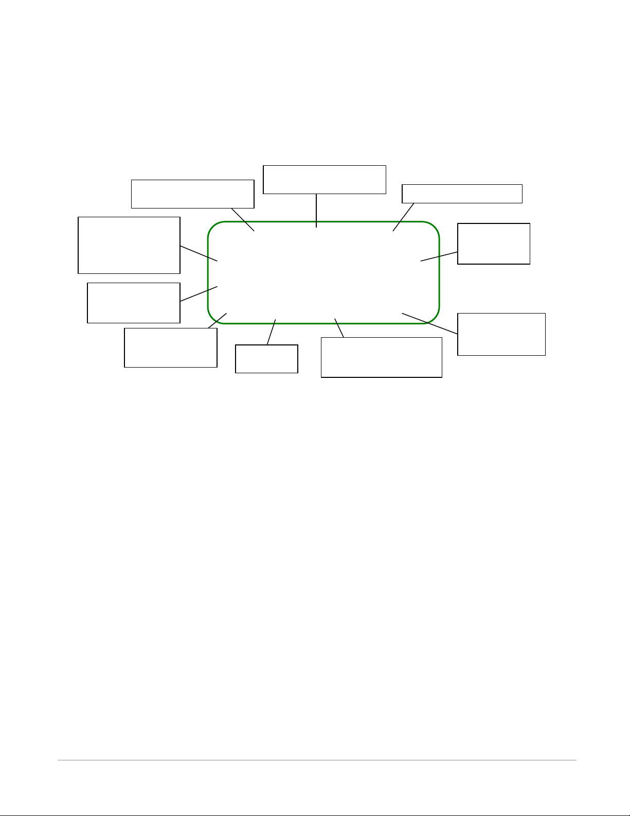
The Monitor feature displays real-time information, allowing active tags to be monitored or tracked. A
sample of how the screen appears in Monitor mode is shown below with labels identifying the information
shown on the screen. Explanations of the information are given in the section 4.2.1.
4.2.1 Monitor Screen Explanations
The explanations given below correspond with the diagram of the Monitor screen above.
A) Coded ping train identification:
This indicates which part of a coded ping train is being received. When the first interval, or sync of a
coded ping train is identified, which requires two pings, an “S” is displayed in the centre of the
Monitor’s top line. With each additional ping, a number is added to the S to indicate how many pings
were received in addition to the sync. When the ping train is complete, the information in the second
and third lines (item I and H in the diagram above) and the time elapsed since the last detection (item J
in the diagram above) are displayed.
B) Time of last detection:
The time, in hours, minutes, and seconds, of the last detection.
C) Signal strength:
The relative strength of the received signal, between 0 and 105 dB. The value is visually represented
on the bar graph to the right of the numeric value. The signal strength is cleared if a signal hasn’t been
received for more than 10 seconds.
IMPORTANT: The signal strength reading is a relative measure of the voltage level present at the
receiver input (0dB = minimum measureable voltage, 105dB = full scale voltage). It is strictly a
relative measure of signal strength and cannot be used to measure the output power of a transmitter in
terms of dB re 1uPa @ 1m.
VEMCO – VR100 Receiver Operating Manual – Page 31
Page 32

Table 4.2-1: Detection Parameter levels.
Parameter
Name
Detection Level
When to Use It
Near
Background noise is almost never mistaken
as a real ping (called a false detect), but
some real pings may be mistaken as
background noise and blocked.
Use when the VR100 is receiving too
many echo signals on the Norm
setting, such as when the tags are in
an enclosed area like a tank.
Norm
Not as aggressive as Near and not as
liberal as Far. Most real pings will be
detected but some background noise may
be mistaken as real pings.
Use this level for almost all
applications.
Far
Nothing is blocked. This allows almost all
real pings to be received but background
noise will be mistaken as real pings.
Use when the tags are far from the
hydrophone or the signal is weak.
This could increase the range.
D) Mute Audio:
The audio heard from either the speaker or headphones is muted by pressing the right selection button
below the word “Mute” in the Monitor screen.. When the Mute button is pressed, the audio is muted
and the word “Mute” briefly becomes “VOL00” to indicate that the volume is zero. The volume is
restored at the same level by pressing the Mute button again. The volume can be restored at a level
above or below the muted volume level by pressing the volume buttons on the front panel (see section
3.1.3).
When the volume level is changed, the “Mute” will change to “VOLXX” for a moment to indicate the
volume level. The XX in “VOLXX” is a numeric representation of the volume level.
E) Gain level:
The number shown indicates the amount of gain the receiver is using, in decibels (dB). The gain can
be manually increased or decreased using the Gain buttons on the front panel (see section 3.1.3). The
gain moves in steps of 6 dB (decibels) and can be changed either manually or automatically. An “M”
next to the gain number indicates the gain is in manual mode while an “A” indicates it’s in automatic
mode (AGC – Automatic Gain Control). The mode is toggled between automatic and manual by
pressing the AGC button on the front panel of the receiver (see section 3.1.3).
NOTE: Since the VR100 receiver has a wide dynamic range, the gain setting is not critical in most
situations. A good setting for general use is to set the gain manually to 12 dB. If the reported signal
strength is consistently greater than 90 dB, reduce the manual gain setting. When working at extended
ranges or if the reported signal strength is consistently weak, increase manual gain setting. In some
adverse situations where the manual gain control does not provide adequate results, try using the AGC
mode
F) Channel number:
The number next to the “CH” indicates the channel number being monitored. Press the number on the
keypad that corresponds with the channel number to monitor that channel.
G) Detection Parameter:
The detection parameter determines what is identified as a received ping and what is considered
background noise (see section 5.3). The three detection parameter settings available are listed in Table
4.2-1. A more detailed explanation is found in section 5.2.
VEMCO – VR100 Receiver Operating Manual – Page 32
Page 33
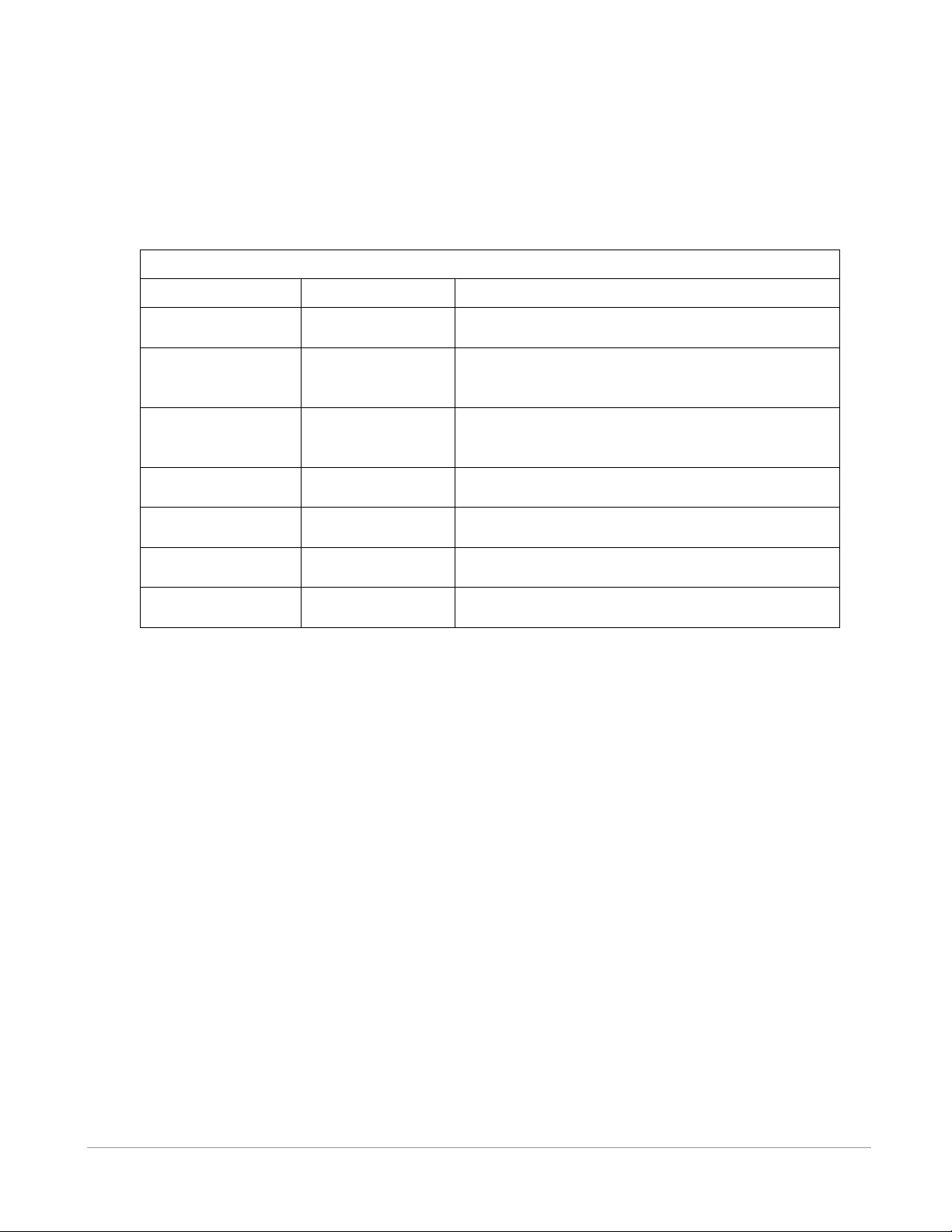
Table 4.2-2: Transmitter types as displayed on the second line of the Monitor screen.
Transmitter Type
Sample
Comments
Continuous pinger
P 1000 ms
“P” indicates the detection is from a continuous
pinger. The period is given in milliseconds (ms).
Continuous 1 sensor
S1 6.3°C
“S1” indicates the data is from a one-sensor
continuous transmitter. The data is shown in the
applicable units.
Continuous 2 sensor
S2 6.3°C 49.5m
“S2” indicates the data is from a two-sensor
continuous transmitter. The data is shown in the
applicable units.
Coded pinger
# 57452
“#” indicates that the coded pinger ID number
follows.
Coded sensor
(with units)
# 58 27.3m
The coded sensor ID number is given followed by
the data with applicable units.
Coded sensor
(without units)
# 8367 RAW=148
The coded sensor ID number is given followed by
the raw sensor data.
Undefined coded tag
Undefined Tag
Indicates a coded ping train was received that could
not be decoded.
H) Transmitter ID and Data:
Transmitter data is displayed as shown in Table 4.2-2. The sensor data received from a sensor
transmitter is displayed in the applicable units. The units shown on the Transmitter Type line are
configurable, as explained in section 4.3.2.5. Continuous sensor transmitters must be set up in the
receiver before they can be monitored (see sections 4.3.4.2 and 4.3.4.3). Data received from a coded
sensor transmitter that has not been set up in the receiver will be displayed as raw data.
I) Frequency / Code Space:
For coded tags, the code space is displayed (see section 5.3 for an explanation of code space). For
continuous pinger and continuous sensor tags the frequency being monitored on this channel is shown
in kilohertz (kHz). Instructions on setting the channel frequency are given in section 4.3.1.2.
J) Last detection elapsed time:
The length of time elapsed (in seconds) since the last detection (“LT” stands for “Last Time”). If the
time has been very long, the display will show 999 to indicate there haven’t been recent detections.
4.3 CONFIGURE
The Configure section of the VR100 receiver allows the receiver to be configured according to a user’s
needs. This includes setting up tags, selecting code maps, setting up channels, turning channels on and off,
adjusting the contrast, turning on the backlight, and setting the units. Each of these features is explained in
the sections to follow.
VEMCO – VR100 Receiver Operating Manual – Page 33
Page 34
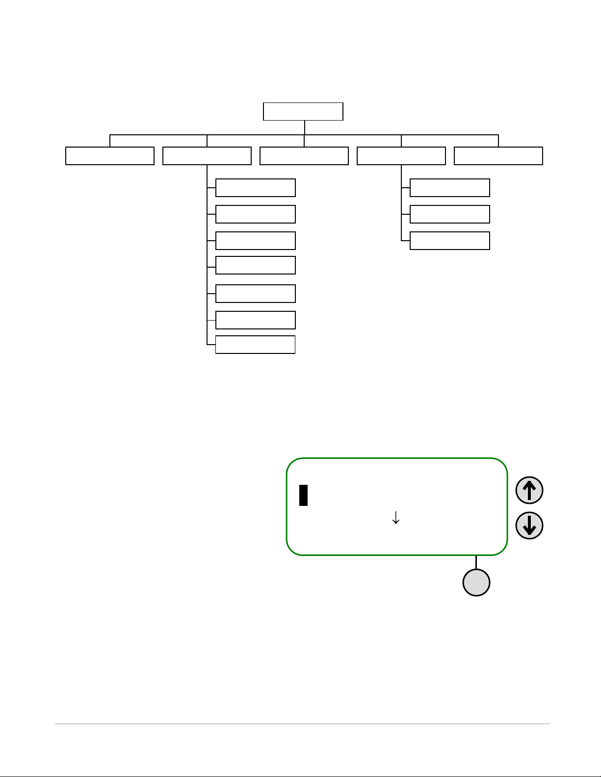
1 Channel
2 System
3 Code Maps
Select
2. CONT. ONE
1. CODED
3. CONT. TWO
2. SYSTEM
3. CODE MAPS
4. SENSOR TAGS
5. LOG
1. CHANNEL
CONFIG
2. CONTRAST
1. TIME
3. BACKLIGHT
5. UNITS
6. VERSION
7. RESET DEF
4. BATTERY
The Configure section has the menu structure displayed in the map below.
Each sub-menu option is associated with a number shown on the screen to the left of the selection, as
shown in the screen below. Selecting a sub-menu option can be performed by using the up and down
arrows on the front panel to move the cursor to the desired sub-menu and then pressing the right selection
button for the Select command. In the screen shown below, the System sub-menu is highlighted with a
flashing cursor. The down arrow in the screen (next to “Code Maps”) indicates that the list extends
downward. The remainder of the list can be accessed by using the down button. An up arrow will appear
in the top line if the list extends upward.
It’s also possible to select a sub-menu by
pressing the corresponding number on the
keypad. For example, the Backlight can be
accessed from the Configure main menu by
pressing the “2” button and then the “3” button
on the keypad. The menu numbers are
included in the previous map for easy
reference.
VEMCO – VR100 Receiver Operating Manual – Page 34
Page 35
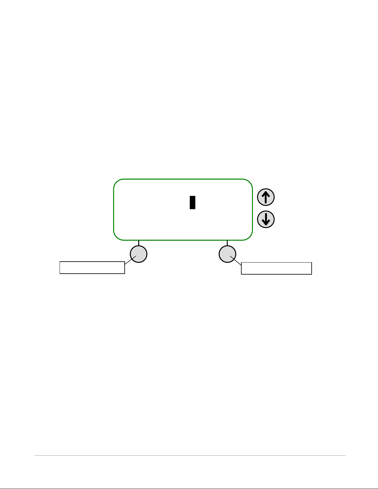
Configure Channel 1 2 3 4 5 6 7 8 ∗ ∗ Set On Configure
Right selection button
Left selection button
4.3.1 Channel (1)
A channel is a group of configuration settings used to listen to VEMCO tags. For example, a channel can
be configured to listen for continuous pingers that operate at 60 kHz. Another channel can be configured
to listen for coded tags operating at 69 kHz. There are eight channels in the VR100 receiver which means
that the receiver can monitor eight different configurations at one time.
When the Channel sub-menu is selected, the screen shown below appears so the desired channel can be
selected. Pressing the up or down arrow to the right of the screen will move the cursor through the list of
channel numbers. When the cursor is on the desired channel, press the right selection button to view or
edit the channel’s configuration.
The desired channel can also be highlighted by pressing the channel number on the keypad. For example,
press “2” on the keypad to highlight channel 2 and press the right selection button to configure the
channel.
4.3.1.1 Enable a Channel
A channel must be turned on before it can be monitored (see section 4.2). To turn a channel on, move the
cursor to the desired channel and then select “Set On” by pressing the left selection button. An asterisk
(∗) below the channel number indicates that channel is on. In the screen shown above, channels 2 and 5
are on. A channel is also turned off by pressing the left selection button when the channel is highlighted.
4.3.1.2 Configure channel
A channel must be configured to monitor deployed tags. When Configure is selected in the “Configure
Channel” screen (see previous page), a summary screen shows the current configuration of the selected
channel. Edit must be selected (press the left selection button) to change the configuration of the channel.
How the channel is configured depends on the type of tag being monitored on this channel. The three
methods are Continuous pingers, Coded, and Continuous sensor (1 or 2 sensors). The steps required for
each of these are listed below.
VEMCO – VR100 Receiver Operating Manual – Page 35
Page 36

4.3.1.2.1 Configure a Channel for a Continuous Pinger:
From the Main screen:
1. Select Config (right selection button).
2. Press “1” on the keypad.
3. Highlight the desired channel number on the keypad by using either the arrow buttons or the numeric
keypad.
4. Press the right selection button to select “Configure”. The channel’s configuration is displayed in a
summary screen.
5. Select “Edit” with the left selection button.
6. Use the up and down arrows to cycle through the four tag types until “Cont Pinger” is displayed and
then select “Next”.
7. Enter the frequency (in kHz) on the key pad and select “Next”. NOTE: If you make an error, keep
pressing the first number of the desired frequency until the cursor returns to the first digit place.
8. Enter the Blanking Interval in milliseconds and then select “Next”. The standard value for a Blanking
Interval is between 75 ms to 250 ms, but smaller or larger values can be used (minimum 50 ms). A
value outside the standard value range must be confirmed on the screen before it will be accepted.
4.3.1.2.2 Configure a Channel for Coded Tags:
From the Main screen:
1. Select Config (right selection button).
2. Press “1” on the keypad.
3. Highlight the desired channel number on the keypad by using either the arrow buttons or the numeric
keypad.
4. Press the right selection button to select “Configure”. The channel’s configuration is displayed in a
summary screen.
5. Select “Edit” with the left selection button.
6. Use the up and down arrows to cycle through the four tag types until “Coded” is displayed and then
select “Next”.
7. Enter the frequency (in kHz) on the keypad and select “Next”. NOTE: If you make an error, keep
pressing the first number until the cursor returns to the first digit place.
8. Select the code map (see section 4.3.3) to be used on this channel and then select “Next”. To use a
non-standard map, the map must be imported using the PC software before a channel can be
configured to use that map.
VEMCO – VR100 Receiver Operating Manual – Page 36
Page 37

4.3.1.2.3 Configure a Channel for Continuous Sensor transmitters
(1 or 2 sensors):
From the Main screen:
1. Select Config (right selection button).
2. Press “1” on the keypad.
3. Highlight the desired channel number on the keypad by using either the arrow buttons or the numeric
keypad.
4. Press the right selection button to select “Configure”. The channel’s configuration is displayed in a
summary screen.
5. Select “Edit” with the left selection button. Use the up and down arrows to cycle through the four tag
types until “Cont 1 Sensor” or “Cont 2 Sensor” is displayed, depending on the tag type, and then select
“Next”.
6. Select the serial number of the tag by either using the arrows to move through the list of tags setup in
the receiver, or by entering the serial number on the keypad and then select “Next”. If the serial
number isn’t setup in the receiver, an “ERR” message appears and the serial number must be entered
(see section 4.3.4.2 and 4.3.4.3).
7. Review the settings in the summary screen.
8. Select “Accept” to accept the configuration and return to the “Configure Channel” screen.
After the configuration settings have been entered, the summary screen displays the settings. The
configuration isn’t saved in the receiver until the “Accept” in the bottom right corner is selected (press the
right selection button). If the changes aren’t acceptable, then use the “Edit” option to repeat the
configuring process or the Menu button to leave the configuration of the channel without saving the
changes.
4.3.1.3 View Channel Configuration
The channel configuration can be either viewed or edited. How to edit the configuration is explained in
section 4.3.1.2. How to view the configuration is described in the steps below.
From the Main screen:
1. Select Config (right selection button).
2. Press “1” on the keypad.
3. Select the desired channel number on the keypad and press the right selection button for “Configure”.
The channel’s configuration is displayed in a summary screen.
4. Select “Accept” (right selection button) to return to the Channel window without making changes to
the channel’s configuration.
VEMCO – VR100 Receiver Operating Manual – Page 37
Page 38

Table 4.3-1: Some conversions from UTC to Standard (winter) Local times.
LOCAL TIME ZONES
CONVERSION
Pacific Standard Time
UTC – 8 hours
Mountain Standard Time
UTC – 7 hours
Central Standard Time
UTC – 6 hours
Eastern Standard Time
UTC – 5 hours
Atlantic Standard Time
UTC – 4 hours
Greenwich Mean Time
UTC
Central European Time
UTC + 1 hours
Eastern European Time
UTC + 2 hours
Moscow Time
UTC + 3 hours
Indian Standard Time
UTC + 5:30 hours
Australian Western Standard Time (China)
UTC + 8 hours
Japan/Korea Standard Time
UTC + 9 hours
Australian Eastern Standard Time
UTC + 10 hours
4.3.2 System (2)
The System menu, a sub-menu of the Config menu, contains seven sub-menus (in order listed in VR100)
Time, Contrast, Backlight, Battery, Units, Version, and Reset to Factory Defaults. Each sub-menu is
associated with a number shown on the screen to the left of the selection.
Selecting a sub-menu option can be performed by using the up and down arrows on the front panel to
move the cursor until the number associated with the desired sub-menu is highlighted and then use the
“Select” command by pressing the right selection button. Another method to select a sub-menu is to press
the corresponding number on the keypad.
4.3.2.1 Time (2-1)
The date and time are displayed on the VR100’s screen in the format YYYY MM DD HH:MM:SS.
Both the date and time can be manually set to any moment on any day, but as soon as the GPS locks the
date and time will be corrected to the local time based on the Coordinated Universal Time (UTC) and the
offset entered in the VR100 by the user.
The GPS system uses Coordinated Universal Time (UTC), the international time standard (see Glossary
for more information). The VR100 receiver will convert the UTC time to the local time as long as the
correct offset has been entered in the receiver (see steps listed below). The offset is the number of hours
behind (a negative value) or ahead (a positive value) of the UTC your local time zone is. For example,
VEMCO is located in the Atlantic Standard Time zone, which is four hours behind UTC. The offset value
“– 4” must be entered in the VR100 for the receiver to display the time at VEMCO. Samples of UTC
conversions are listed in Table 4.3-1.
VEMCO – VR100 Receiver Operating Manual – Page 38
Page 39
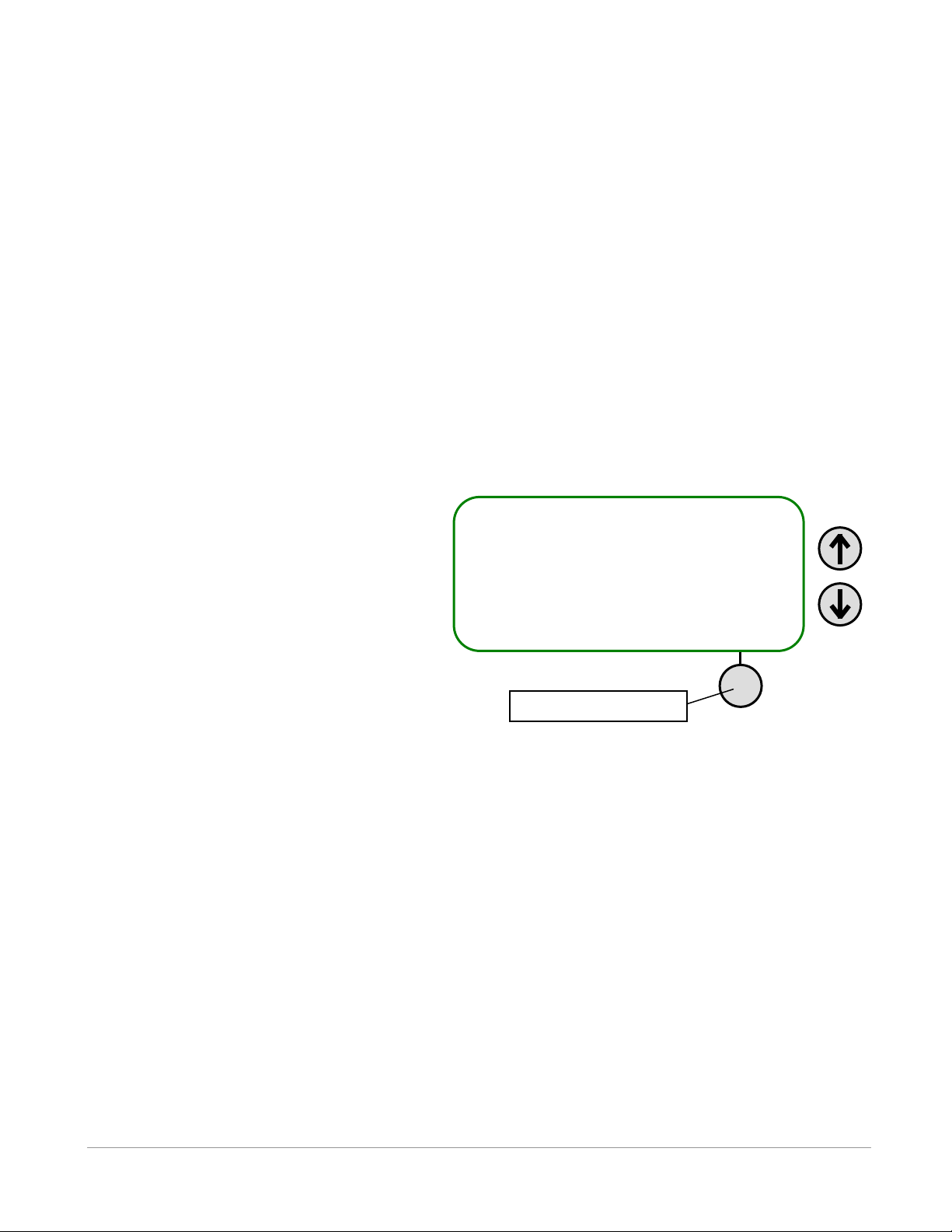
Set Local Time
2009 01 26 09:35:54
Set: 2009 01 26 USER
Accept
Right selection button
The UTC offset and the local date and time are set by following the steps below from the Main screen:
1. Select Config (right selection button).
2. Press “2” on the keypad.
3. Press “1” on the keypad.
4. Enter the UTC offset (see Table 4.3-1) on the keypad. This is a number between – 12.0 and 12.0. The
negative, if needed, must be entered before the number or the number will be erased and have to be reentered.
NOTE: One decimal place is available for time zones that have an offset of more than a multiple of an
hour. For example, Newfoundland Standard Time (NST) is 3.5 hours behind UTC so the offset value
“–3.5” would be entered.
5. Press the right selection button to accept the offset value. The screen shown below will appear for the
date and time to be set.
6. Use the up and down arrow buttons to move the cursor horizontally to the desired component of the
date/time.
7. Enter the new numbers on the keypad.
8. Repeat steps 6 and 7 until the date and time are entered as desired.
9. Press the right selection button to accept the changes.
The Set Local Time screen also displays the
date the time was last set and by whom, either
the user (USER), the GPS (GPS), or the PC
software (USB). If the display reads DFLT,
then either the time has never been set or the
time was lost if the battery was fully drained of
power and recharged. The time is maintained
as long as the battery is charged.
4.3.2.2 Contrast (2-2)
The contrast between the text and the background on the VR100’s screen can be adjusted. The contrast
should be set so the text on the screen is clearly visible without any of the background lines being visible.
To adjust the contrast, follow the steps below.
From the Main screen:
1. Select Config (right selection button).
2. Press “2” on the keypad.
3. Press “2” on the keypad.
4. Use the left selection button to decrease the contrast (Less) or the right selection button to increase the
contrast (More) to the desired level.
5. Press the MENU button to accept the changes.
VEMCO – VR100 Receiver Operating Manual – Page 39
Page 40

4.3.2.3 Backlight (2-3)
There are three options available for backlight operations, ON, OFF, and SMART. The ON option turns
the backlight on and it remains on until it is turned off using the OFF option. The backlight should only be
needed indoors and at night. Operating the VR100 with the backlight on will greatly reduce the operating
time between battery charges. The SMART option leaves the backlight off if the keypad is inactive but
will turn the backlight on for five seconds when a button is pressed on the keypad.
To change the backlight setting, from the Main screen:
1. Select Config (right selection button).
2. Press “2” on the keypad.
3. Press “3” on the keypad. The current backlight setting is displayed with an arrow symbol.
4. Press the up or down arrow button until the desired option is shown on the display.
5. Press the button attached to “Accept” to accept the change, or “Cancel” to exit the menu without
changing the backlight setting.
4.3.2.4 Battery (2-4)
The battery voltage level and internal status can be viewed on the VR100 receiver display by following the
steps listed below.
NOTE: If an external power source is connected to the receiver, then the voltage reported by the VR100 is
the voltage of the external power supply and not the internal battery. Turn off the receiver, unplug the
external power supply, and turn the VR100 on to read the battery voltage with the steps below.
From the Main screen:
1. Select Config (right selection button).
2. Press “2” on the keypad.
3. Press “4” on the keypad.
The values displayed from left to right are as follows:
R – regulated voltage
B – battery voltage
T – internal temperature (oC)
BT – battery temperature (oC, displays - - if not available1)
4.3.2.5 Units (2-5)
The temperature and depth units are selected on a global level. This means that all temperatures values on
all screens will have the temperature units selected in the Units sub-menu, and all depth values on all
screens will have the depth units selected in the Units sub-menu. The choices are listed in Table 4.3-2.
Follow the steps below to select the units.
1
Battery temperature is not available on VR100-100 receivers.
VEMCO – VR100 Receiver Operating Manual – Page 40
Page 41
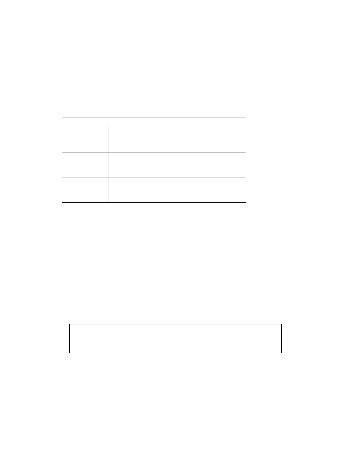
Table 4.3-2: Sensor Units available for global setting.
Temperature
Degrees Centigrade (°C)
Degrees Fahrenheit (°F)
Depth
Meters (m)
Feet (ft)
Pounds per square inch (PSI)
Acceleration
Meters per second per second (m/s2)
Feet per second per second (ft/s2)
G (units gravitational force)
WARNING:
The Reset command removes all sensor transmitters from the tag database
and clears the channel configurations.
From the Main screen:
1. Select Config (right selection button).
2. Press “2” on the keypad.
3. Press “5” on the keypad.
4. Press “1” for temperature units or “2” for depth units.
5. Use the arrow buttons to move through the list of unit options (shown in Table 4.3-2) until the desired
unit is seen on the screen, with the flashing cursor.
6. Press “Select” (right selection button).
4.3.2.6 Version (2-6)
The version sub-menu contains information pertaining to this particular receiver, such as the serial number
and the firmware version number. This information is only needed if it is requested during your
communications with VEMCO.
4.3.2.7 Reset to Factory Defaults (2-7)
The Reset to Factory Defaults option will return the VR100 to the factory default settings, removing all
sensor transmitters from the tag database and clearing the channel configurations. A confirmation window
will appear to verify that this is the desired action before the receiver is reset. Do not perform other tasks
on the VR100 while the settings are being returned to the factory default values (approximately eight
seconds).
VEMCO – VR100 Receiver Operating Manual – Page 41
Page 42

TABLE 4.3-3: Current VEMCO Code Maps
Map Name
Code Spaces2
Notes
MAP-113
A69-1105, A69-1303,
A69-1601, A69-1602,
A69-9001/9002,
A69-9004, A69-9006
Default Map for 69 kHz Coded Tags
MAP-311
A81-1008, A81-1105,
A81-1206, A81-1303
Default Map for 81 kHz Coded Tags
MAP-413
A180-1701, A180-1702
Default Map for 180 kHz Coded Tags
4.3.3 Code Maps (3)
4.3.3.1 Understanding Code Maps
There are three default code maps used with VEMCO coded tags, MAP-113 for 69 kHz, MAP-413 for 180
kHz and MAP-311 for 81 kHz. These maps are installed by default. Several legacy maps can be installed
on the receiver using the VR100HS PC Software, but should only be used if directed by Vemco Customer
Support. The current default map definitions are listed in Table 4.3-3.
IMPORTANT: VEMCO tag datasheets will contain a Code Space name which fully defines the tag
parameters necessary for the receiver. Ensure that you select a Code Map that contains all the code
spaces required for your tags.
4.3.3.2 Viewing Code Maps
To view the Code Spaces supported by each map, follow the steps listed below.
From the Main screen:
1. Select Config (right selection button).
2. Press “3” on the keypad.
3. Select the desired code map number on the keypad.
4. Select “View” by pressing the right selection button.
5. Use the arrow buttons to cycle through the Code Spaces supported by the Code Map.
2
Code Space is new nomenclature for VEMCO tag types. It has been introduced to remove ambiguity over tag
parameters. VEMCO tag datasheets will contain a code space name.
VEMCO – VR100 Receiver Operating Manual – Page 42
Page 43

NOTE
Only tags with
sensors need
to be entered
in the receiver.
Pingers don’t
need to be
entered.
4.3.4 Sensor Transmitters (4)
The Sensor transmitters menu, a sub-menu of the Config menu, contains three sub-menus. Each sub-menu
allows sensor transmitters to be set up in the receiver so the data will be displayed in the correct units. A
total of 750 sensor transmitters may be set up in the receiver at one time. The sub-menus are (in order):
Coded, Cont One, and Cont Two.
When the VR100 has 750 tags setup, meaning the tag storage capabilities are full, a
new tag can’t be entered until an existing tag is deleted. To delete a tag, first
highlight the tag by either scrolling through the list of entered serial numbers or by
entering the serial number on the keypad. When the desired tag is highlighted,
select Delete in the bottom left corner of the screen (press the left selection button).
A confirmation screen will appear to verify that you want to delete the tag. Note that
the delete function is only available when the sensor database is full.
Information must be entered for sensor transmitters for the data to be displayed in the correct units. Data
received from coded sensor transmitters can be displayed without this information stored in the receiver,
but it will be raw data and need to be converted manually. The necessary information is entered by
following the steps below.
4.3.4.1 Setting Up Coded Sensor Transmitters (4-1)
From the Main screen:
1. Select Config (right selection button).
2. Press “4” on the keypad.
3. Select number 1 from the list of sub-menus.
NOTE: If there are no previously setup tags, then the receiver will go directly to the New tag screen
and the process will begin with step 5.
4. Select sensor transmitter:
a. If editing an existing sensor transmitter:
i. Highlight the desired tag by either scrolling through the list of entered serial numbers or
entering the serial number on the keypad.
ii. Select “Edit” by pressing the right selection button.
b. If entering a new sensor transmitter:
i. Select “New” by pressing the left selection button.
5. Enter the serial number.
6. Enter the frequency in kilohertz (kHz).
7. Select the code space from the list provided by pressing the up or down arrow until the correct code
space name is shown on the display.
8. Enter the Tag ID number.
9. Enter the slope from the Transmitter Specification manual. A negative symbol (if applicable) can be
entered before or after the number is entered by pressing the “+/−” button on the keypad.
10. Enter the intercept from the Transmitter Specification manual. A negative symbol (if applicable) can
be entered before or after the number is entered by pressing the “+/−” button on the keypad.
11. Select the data type - depth, temperature or acceleration.
12. Press the right selection button to select “Accept”.
VEMCO – VR100 Receiver Operating Manual – Page 43
Page 44

NOTE: For coded two-sensor tags, two separate sensor tag entries are required – one for each tag ID
(sensor). Since the VR100 does not allow duplicate serial numbers in the sensor database, the serial
number for the second sensor entry must be different than the first sensor entry. We recommend that
you use the serial number provided on the specification sheet for the first sensor entry, and the same
serial number with a prefix for the second sensor entry. For example, using “20” as the prefix:
Sensor 1 SN: 1034857
Sensor 2 SN: 201034857
4.3.4.2 Setting Up One-sensor Continuous Sensor Transmitters (4-2)
From the Main screen:
1. Select Config (right selection button).
2. Press “4” on the keypad.
3. Select number 2 from the list of sub-menus.
NOTE: If there are no previously setup tags, then the receiver will go directly to the New tag screen
and the process will begin with step 5.
4. Select sensor transmitter:
a. If editing an existing sensor transmitter:
i. Highlight the desired tag by either scrolling through the list of entered serial numbers or
entering the serial number on the keypad.
ii. Select “Edit” by pressing the right selection button.
b. If entering a new sensor transmitter:
i. Select “New” by pressing the left selection button.
5. Enter the serial number and press “Next”.
6. Enter the frequency in kilohertz (kHz) and press “Next”.
7. Enter the slope from the Transmitter Specification manual and press “Next”. A negative symbol (if
applicable) can be entered before or after the number is entered by pressing the “+/−” button on the
keypad.
8. Enter the intercept from the Transmitter Specification manual and press “Next”. A negative symbol (if
applicable) can be entered before or after the number is entered by pressing the “+/−” button on the
keypad.
9. Select the data type - depth or temperature and press “Next”.
10. Enter the Minimum Period value found in the Transmitter Specification manual and press “Next”. The
default value is 200 ms.
11. Enter the Maximum Period value found in the Transmitter Specification manual and press “Next”.
The default value is 2500 ms. NOTE: If the Maximum Period entered is not greater than the
Minimum period then the settings will revert to the default values.
12. Press the MENU button to exit the coded sensor transmitter setup screen.
4.3.4.3 Setting Up Two-sensor Continuous Sensor Transmitters (4-3)
From the Main screen:
1. Select Config (right selection button).
2. Press “4” on the keypad.
VEMCO – VR100 Receiver Operating Manual – Page 44
Page 45

3. Select number 3 from the list of sub-menus.
NOTE: If there are no previously setup tags, then the receiver will go directly to the New tag screen
and the process will begin with step 5.
4. If editing an existing tag:
a. Highlight the desired tag by either scrolling through the list of entered serial numbers or entering
the serial number on the keypad.
b. Select Edit in the bottom right corner.
c. Skip to Step 6.
5. If entering a new tag, select New in the bottom left corner.
6. Enter the serial number and press “Next”.
7. Enter the frequency in kilohertz (kHz) and press “Next”.
8. Press “Next” if the sync value is 1150 ms. Otherwise, enter the sync value and press “Next”. The
sync value is found in the Transmitter Specification manual.
9. Enter the slope for sensor 1 from the Transmitter Specification manual and press “Next”. A negative
symbol (if applicable) can be entered before or after the number is entered by pressing the “+/−”
button on the keypad.
10. Enter the intercept for sensor 1 from the Transmitter Specification manual and press “Next”. A
negative symbol (if applicable) can be entered before or after the number is entered by pressing the
“+/−” button on the keypad.
11. Select the data type for sensor 1, usually temperature, and press “Next”.
12. Enter the slope for sensor 2 from the Transmitter Specification manual and press “Next”. A negative
symbol (if applicable) can be entered before or after the number is entered by pressing the “+/−”
button on the keypad.
13. Enter the intercept for sensor 2 from the Transmitter Specification manual and press “Next”. A
negative symbol (if applicable) can be entered before or after the number is entered by pressing the
“+/−” button on the keypad.
14. Select the data type for sensor 2, usually depth, and press “Next”.
15. Enter the Minimum Period value found in the Transmitter Specification manual and press “Next”. The
default value is 200 ms is the default.
16. Enter the Maximum Period value found in the Transmitter Specification manual and press “Next”.
The default value is 2500 ms. NOTE: If the Maximum Period entered is not greater than the
Minimum period then the settings will revert to the default values.
17. Press the right selection button to select “Accept”.
4.3.5 Log (5)
The Event Log screen contains the number of recorded events and the percentage of log memory used. It
also contains the option to erase the event log.
The Event Count line reports the number of events stored to memory. An event is either a detected ping
from a tag, a GPS position fix, or a system action (like a start up, a change to the receiver’s configuration,
etc.). The number of events increases until the memory is full at approximately 85000 events.
The Use line in the Event Log screen shows the percentage of log memory used in the VR100 receiver,
both numerically and graphically. When 100 % of the log memory is full, the memory must be erased
before more events can be logged.
VEMCO – VR100 Receiver Operating Manual – Page 45
Page 46
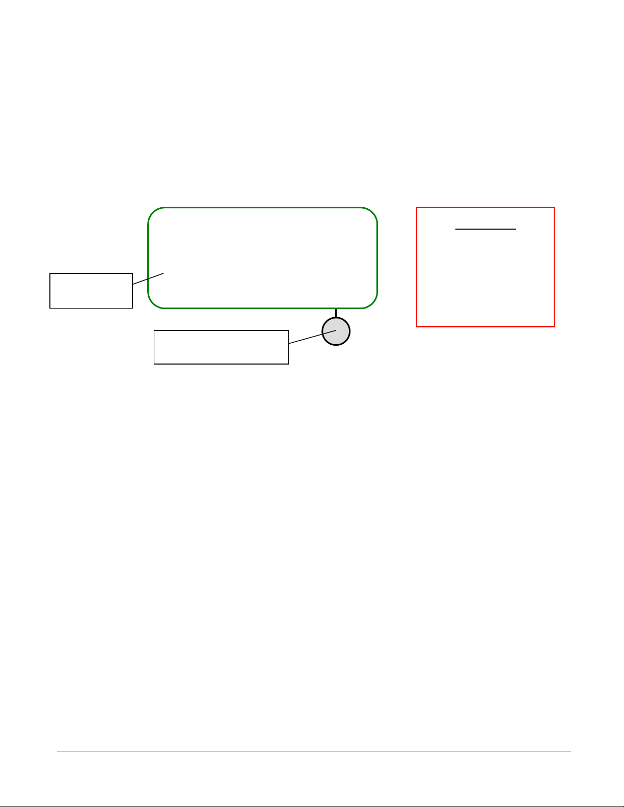
IMPORTANT
When the VR100 memory
is full, it must be erased
before more data can be
stored. Use the VR100HS
software to copy data to a
computer before erasing
the VR100’s memory.
Event Log
Event Count: 42500
Use: 50 % ▊▊▊
Erase
Press right selection
button to erase memory
Amount of
memory used
The event log memory is erased by first pressing the right selection button. A confirmation window
appears before the log is erased so the log can’t be accidentally erased. Erasing the event log will only
erase the events that have occurred to the VR100 receiver and not the channel settings or the sensor tag
information.
The memory can be erased from either the Event Log screen or from within the PC software, but the
memory should only be erased after the log has been copied to a computer (see the software manual for
details).
VEMCO – VR100 Receiver Operating Manual – Page 46
Page 47

IMPORTANT
The VR100 internal GPS is designed to provide accurate time sync data for the system clock and
GPS coordinates for the purpose of marking approximate position whenever a VEMCO transmitter
is detected within acoustic range (up to 2 km distance). The VR100 GPS was not intended to
provide precise tracking positions or as a navigation aid designed to assist in planning routes. The
VR100 GPS is not to be used for any applications in which the reliability or accuracy could result in
a situation of personal injury.
For optimal GPS operation ensure that you are using the latest version of VR100 firmware
version 3.2.0 or later.
Check version using Config menu 2 System 6 Version MCORE
We recommend that you use a WAAS enabled handheld GPS receiver along with the VR100.
The Global Positioning System (GPS) is operated by the U.S. Government, which is solely
responsible for the accuracy and maintenance of the GPS network. The accuracy of position fixes
can be affected by the periodic adjustments to GPS satellites made by the U.S. government and
are subject to change in accordance with the Department of Defence civil GPS user policy and the
Federal Radio navigation Plan. Accuracy can also be affected by poor satellite geometry and
obstructions, like buildings and large trees, and boat canopies.
5 APPENDIX
5.1 ADDITIONAL INFORMATION
5.1.1 GPS
The GPS (Global Positioning System) works by coordinating position information from multiple satellites.
It needs to see three satellites to get a good position fix. Once it sees even one satellite, it can download an
almanac from that satellite to get an idea of where to expect other satellites to be located, and therefore get
its three satellites faster.
On the VR100 receiver screen, when the GPS is locked and getting position fixes then the longitude and
latitude will be displayed on the second line of the main menu, in decimal degrees:
XX.XXXXXA XXX.XXXXXB
where X is a digit (0-9), A is N (North) or S (South), and B is E (East) or W (West).
When the VR100 is not locked, the GPS message displayed will be one of those listed in Table 5.1-1. The
status of the GPS is updated every 5 seconds.
VEMCO – VR100 Receiver Operating Manual – Page 47
Page 48
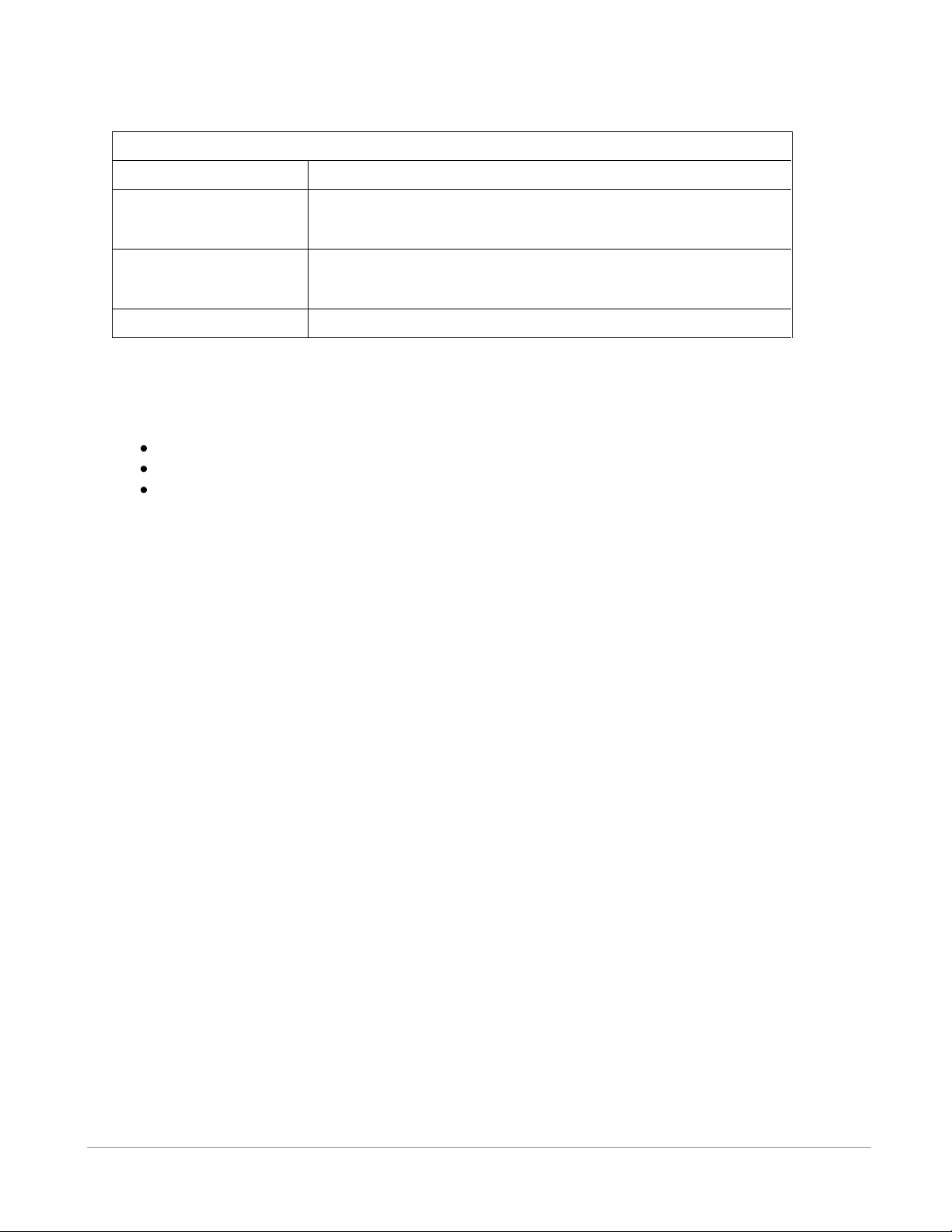
Table 5.1-1: GPS status messages.
Display
Meaning
Getting Fix
GPS is searching for satellites. The GPS must see at least 3
satellites for a minimum of 15 seconds to begin giving position
fixes.
High PDOP
GPS sees at least 3 satellites, but cannot get a fix because satellite
PDOP is too high. This indicates the satellites in view are not
positioned well enough to provide a reliable fix.
Rcvr Fault
GPS Antenna is broken; report to VEMCO for instructions
The accuracy of GPS fixes can be improved by a Satellite Based Augmentation System (SBAS), which is
only available is certain areas of the world. The VR100-200 hardware version supports these SBAS
services, depending on your geographic location:
WAAS (North America)
EGNOS (Europe)
MSAS (Japan)
The VR100 will utilize SBAS if the signal is detected, and this will be indicated by displaying “SBAS” on
the third line of the main menu screen.
This feature is not supported by the VR100-100 hardware version.
VEMCO – VR100 Receiver Operating Manual – Page 48
Page 49
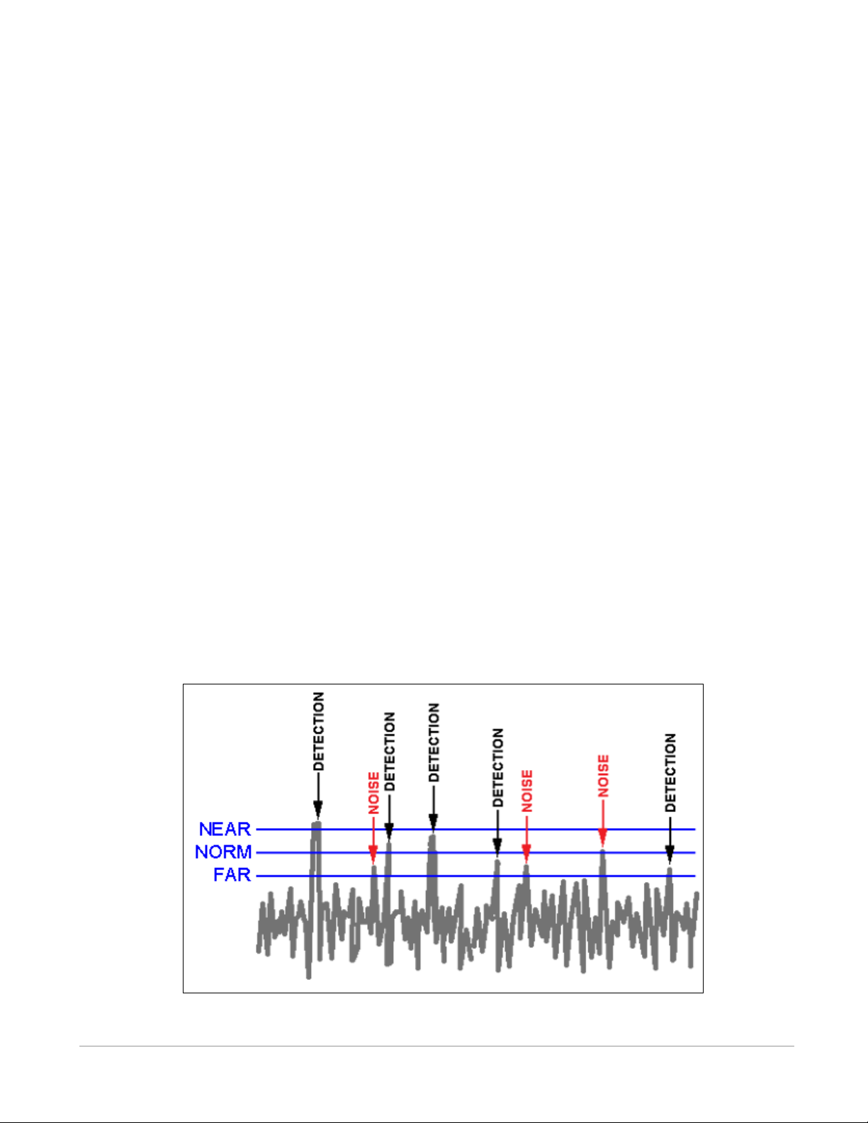
NOTE: This example has been exaggerated for illustration purposes. In most cases there
will be no false detections with Near or Norm, and very few with Far.
5.2 DETECTION PARAMETERS
The detection parameter levels are used to determine how a real signal, referred to as a detection, is
distinguished from background noise. The VR100 constantly receives a signal similar to the one shown in
the drawing below. This usually includes a large amount of background noise from sources such as noises
in the hydrophone’s environment, electronic components in the receiver, etc. A “cut-off” level must be
selected to decide what is a genuine detection and what is a spike in the background noise. A spike in the
background noise that is mistakenly identified as a detection is called a “false-detection”. The VR100
allows the user to select one of three levels to be used to determine what is considered a genuine detection.
These levels are Near, Norm, and Far.
1. NEAR: This is the “safest” detection level because it rejects anything that could be noise, nearly
eliminating false-detections. Unfortunately, it may reject fainter signals that are real. In the sketch
below, everything over the “Near” line is considered a genuine detection. In this case, only one
signal (the first one) was accepted. The other four signals were incorrectly considered to be
background noise and weren’t included. Use the “Near” level when the “Norm” level is receiving
too many echoes. This can happen when the tags are in an enclosed area like a tank.
2. NORM: This is the medium level. It rejects some noise but also allows some noise to be mistaken
as detections (false-detections). This level will correctly accept more detections than the “Near”
setting but will still mistake some genuine signal as background noise. In the sketch below,
everything over the “Norm” line is considered a genuine detection. In this case, four signals were
accepted – the first three were genuine detections and the last was noise. Use the “Norm” level for
general use.
3. FAR: This level has more false detections. All genuine detections will be accepted, but a larger
number of false-detections will also be accepted. In the sketch below, everything over the “Far”
line is considered a genuine detection. In the sample below, eight detections were reported but
only five of them were genuine detections. The other three detections were actually noise (false-
detections). Use the “Far” level when the tags are far from the hydrophone and the signals
received from the tags are weak.
VEMCO – VR100 Receiver Operating Manual – Page 49
Page 50

5.3 GLOSSARY
Automatic Gain Control (AGC): Automatic Gain Control changes the gain level as the VR100
deems necessary without input from the user. The VR100 uses signal strength to determine if the
gain level should increase, decrease, or remain constant. In most conditions, the VR100 should be
used in the manual gain mode. Section 4.2 explains how to switch between manual and automatic
gain control.
Blanking Interval: The Blanking Interval is the length of time (in milliseconds) after an acoustic signal
has been received on a given channel in which the VR100 will ignore any subsequent signals on
that same channel. This is to eliminate the reception of echoes by the receiver.
Background noise: Background noise is the total noise from all sources other than the sound of interest.
Channel: A channel in the VR100 is a group of configuration settings used to listen to VEMCO tags.
For example, a channel can be configured to listen for continuous pingers that operate at 60 kHz.
Another channel can be configured to listen for coded tags operating at 69 kHz. Up to eight
channels can be monitored simultaneously.
Code Map: A Code Map describes a collection of Code Spaces. When a receiver is configured with a
particular Code Map, it can detect and decode all the types of transmitters in that map. See Table
4.3-3 for a list of supported maps. MAP-113 is the current default map for 69kHz transmitters and
allows the VR100 to properly detect and decode all currently supported VEMCO Tags.
Code Space: Code Space describes all the parameters that a receiver needs to properly decode each tag.
These parameters include the numbers of pulses, the coding technique, the length of the first
interval etc. Tag specification sheets will always include a Code Space value. Users must ensure
that they select a code map that contains the code space(s) of the tags they are detecting.
A69-1303 is an example of a valid Code Space label. The “A69” indicates an Acoustic Tag
operating at a frequency of 69 kHz. The “1303” is a unique number that is understood by the
receiver firmware to determine how to detect and decode the tags. The VR100 Receiver will report
tag detections as Code space and ID#. It is important to note that a tag that transmits a Code spaceID#, e.g., A69-1303-2056, is a different transmitter then one with a label of A69-1206-2056. The
ID codes are the same but the Code Space is different and uniquely identified by the VR100!
Coded tags: Coded tags transmit a series of acoustic pings to form an ID (identity) number recognized
by the receiver. The pings form a “ping train” that is usually followed by either a fixed or random
delay. The type and length of the delay is set at the time the tag is ordered and cannot be changed
once the tag is built.
Continuous tags: Continuous tags transmit the acoustic pings continuously, without delays between
transmissions. Continuous tags are available with or without sensors.
Coordinated Universal Time (UTC): UTC is the international time standard. It is the current term for
what was commonly referred to as Greenwich Mean Time (GMT). Zero (0) hours UTC is
midnight in Greenwich, England, which lies on the zero longitudinal meridian. Samples of the
conversion factor needed to convert from UTC to the local time zone are found in Table 4.3-1.
VEMCO – VR100 Receiver Operating Manual – Page 50
Page 51
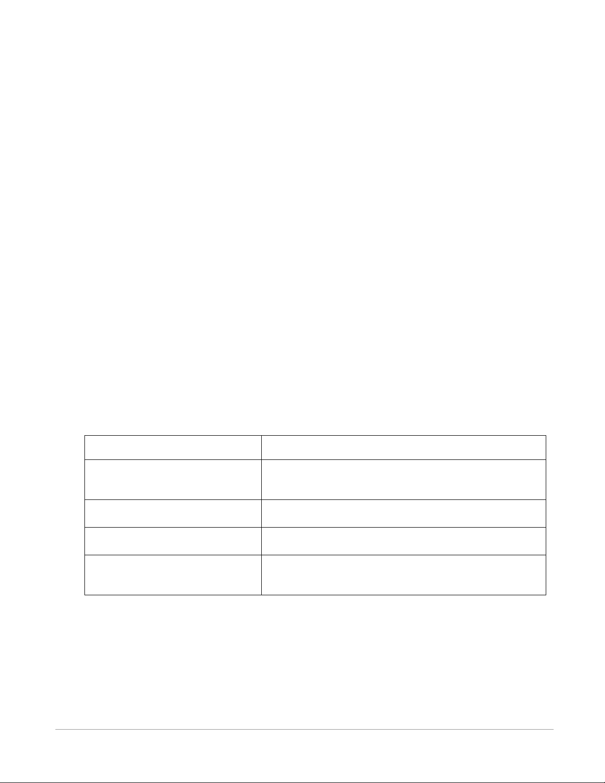
Trouble
Possible Solution
Can’t hear audio signal but detection
indicator light is flashing.
1. Volume is too low.
2. Audio is muted (see section 4.2.1).
3. Headphones are plugged into VR100.
Display blinks and receiver makes a
repeated clicking sound.
Battery is low and needs to be re-charged (see section 3.3.1).
Receiver won’t turn on after I turned
it off.
The battery may need to be charged (see section. 3.3.1).
Computer does not see the receiver
when the USB cable is plugged in.
1. Turn VR100 off and then back on.
2. If using an external USB hub, as suggested (see front of
manual), then check that the hub is powered.
Decibel (dB): A decibel is a logarithmic unit used for measuring the strength of a signal. A decibel is
one tenth of a "bel".
Detection Parameters: The detection parameter determines what is identified as a received ping and
what is considered background noise (see section 4.2.1).
Pinger: A VEMCO tag that contains no sensors. It can have either a coded or continuous transmission
schedule.
Position dilution of precision (PDOP): PDOP is a unitless measure that indicates when satellite
geometry will provide the most accurate results. A low PDOP indicates the satellites are nicely
arranged to give a good position. The PDOP may be improved by facing the VR100 GPS antenna
towards the equator where more satellites are located.
Tag: A VEMCO tag is an acoustic transmitter that is attached to a marine creature and transmits an
acoustic signal. The acoustic signal is received by a VEMCO receiver. VEMCO tags can transmit
either a coded or continuous signal, with or without sensor data. After a tag is powered, it will
continue to broadcast according to factory setup until powered down.
Sensor transmitter: A VEMCO tag that has at least one sensor. The type of sensor is usually included
in the transmitter’s name. For example, a V16P has a pressure (depth) sensor and the V16T has a
temperature sensor. A sensor transmitter can also have either a coded or continuous transmission
schedule.
5.4 TROUBLESHOOTING
VEMCO – VR100 Receiver Operating Manual – Page 51
Page 52
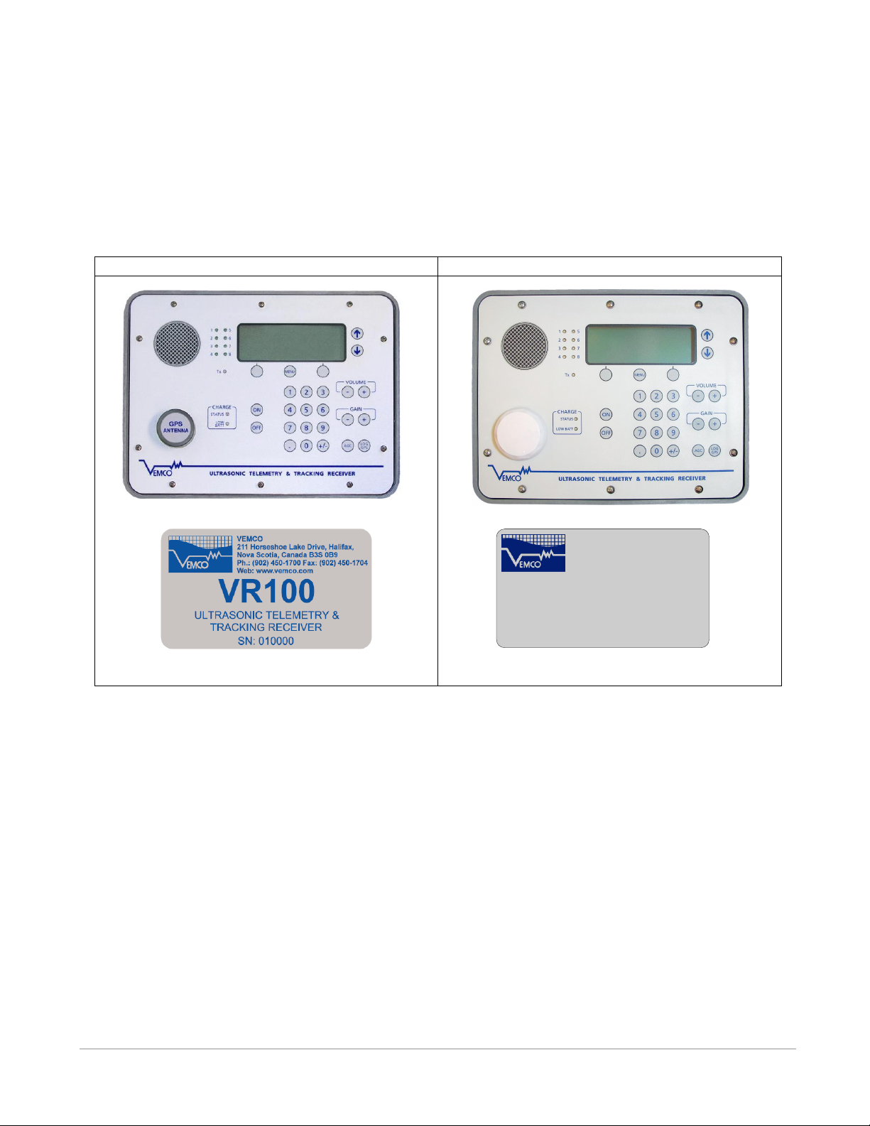
VR100-100
VR100-200
VEMCO
+1-902-450-1700
www.vemco.com
VR100
ULTRASONIC TELEMETRY &
TRACKING RECEIVER
PN: VR100-200 SN: XXXXXX
5.5 VR100 HARDWARE VERSIONS
There are two major versions of the VR100 hardware covered by this manual, VR100-100 and VR100-
200. You can identify the hardware version of your VR100 by observing the nameplate label and the GPS
antenna. Both models provide the same acoustic receiver functionality, but VR100-200 has a new GPS and
antenna with improved performance specifications and support for WAAS, EGNOS and MSAS
augmentation for enhanced accuracy.
VEMCO – VR100 Receiver Operating Manual – Page 52
Page 53
Product name:
VR100 Ultrasonic Telemetry & Tracking Receiver
Frequency Range:
12 to 200 kHz
Operating Temperature:
-15°C to +40°C. Battery life will be reduced below 0°C.
Ingress Protection Rating:
IPX5; see section 3.1 for details
Battery Life:
Approximately 12 hours when operating between 10°C and 40 °C
with backlight off, less with backlight on.
AC Power Supply:
(battery charger)
100-240V; 50/60Hz; 0.80A max
Indoor use, altitude up to 2,000 m., maximum relative humidity is
80%, mains supply voltage fluctuations up to 10% of the nominal
voltage, overvoltage category II, pollution degree 2.
DC Power Supply:
10 - 15VDC; 3A max
Physical Dimensions:
34 cm x 32 cm (with handle extended) x 15 cm
Physical Weight:
VR100-200: 6.5 kg
VR100-100: 5.2 kg
GPS Accuracy:
VR100-200:
Horizontal: < 5 meters (16 feet), 90% typical* (GPS only)
< 4 meters (13 feet), 90% typical* (with WAAS, EGNOS
or MSAS)
VR100-100:
Horizontal: < 9 meters (30 feet), 90% typical*
GPS only (does not support augmentation such as WAAS, EGNOS
or MSAS)
VR100 firmware 3.0.3 or later required
* Subject to accuracy degradation under the United States Department of Defense-imposed
Selective Availability Program.
WAAS = Wide Area Augmentation System; EGNOS=European Geostationary Navigation
Overlay Service; MSAS=Multi-functional Satellite Augmentation System
5.6 SPECIFICATIONS
5.7 CLEANING INSTRUCTIONS
Clean VR100 with a damp cloth and mild detergent.
Do not use solvents. Do not use abrasive cleaners. Do not allow oils, resins, paints, or similar gummy
materials to enter the case vent – these can clog the vent and prevent it from operating properly, possibly
creating a safety hazard.
VEMCO – VR100 Receiver Operating Manual – Page 53
Page 54

5.8 CONTACT INFORMATION
Product manufactured by
VEMCO Division
AMIRIX Systems Inc.
211 Horseshoe Lake Drive
Halifax, Nova Scotia
Canada B3S 0B9
Phone: +1-902-450-1700
Fax: +1-902-450-1704
Web Site: www.vemco.com
Email: [email protected]
VEMCO – VR100 Receiver Operating Manual – Page 54
Page 55

AGC, 22, 32, 50
Background noise, 32, 50
Battery
Charge indicator lights, 26
Charging, 25
Storage, 27
Voltage level, 40
Case
Connectors, 18
Front panel, 20
Opening, 17
Channel, 8, 9, 10, 11, 21, 32, 35, 37, 50
Configure, 35
Turn on, 35
View configuration, 37
Coded Maps
Understanding, 42
Viewing, 42
Connectors, 18
Protective cap, 8, 18, 19, 22
Using, 18
Detection parameter, 8, 32, 49, 51
Event Count, 45
Front panel
Audio speakers, 21
Detection indicators, 21
Gain control, 21
LCR screen, 21
Volume control, 21
Gain, 8, 16, 21, 32, 50
6 INDEX
GPS, 6, 29, 45, 47
Antenna, 22
Button, 21
Status line, 30
Headphones, 11, 12, 17, 21, 32
Headphone jack, 24
Hydrophone, 6, 8, 11, 12, 17, 18, 22, 49
LCR screen
Backlight, 40
Contrast, 39
Main menu, 29
Memory
Erase Event log, 16, 45
View amount used, 15, 45
Mute, 32
Reset to Factory Defaults, 41
Sensor transmitter
Intercept, 13, 14, 43, 44, 45
Setup coded, 43
Setup continuous, 44
Slope, 13, 14, 43, 44, 45
Used with VR100, 43
Storage, 27
Tag
Pinger, 7, 9, 11, 12, 33, 36
Sensor Transmitter, 7, 9, 13, 33, 51
Units, 8, 40
USB cable, 23
UTC, 29, 38, 50
VEMCO – VR100 Receiver Operating Manual – Page 55
 Loading...