

Page 1
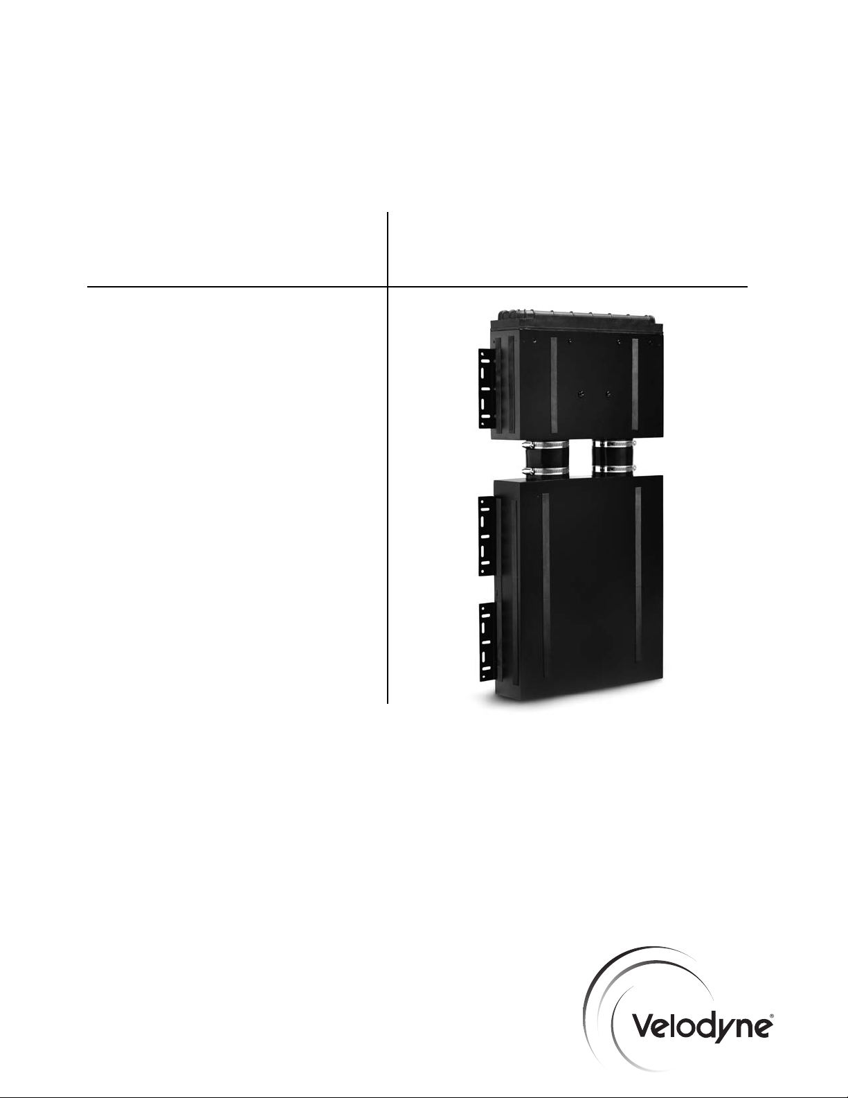
SC-IW
(In-Wall)
Subwoofer
SubContractorTMSeries
INSTALLATION
MANUAL
Page 2
Caution!
.
www.velodyne.com
SC-IW Installation Manual
i
Page 3
Attention!
.
www.velodyne.com
SC-IW Installation Manual
ii
Page 4

Vorsicht!
.
www.velodyne.com
SC-IW Installation Manual
iii
Page 5
Attenzione!
.
www.velodyne.com
SC-IW Installation Manual
iv
Page 6

Table of Contents
P
roduct Overview.................................................................................................1
- Driver Technology ...........................................................................................1
- Cabinet Technology .........................................................................................1
Installation Overview .............................................................................................3
New Construction Installation - Standard Grille .........................................................4
New Construction Installation - Designer Grille .......................................................15
Retro-Fit Installation - Designer Grille ....................................................................25
Retro-Fit Installation - Standard Grille ....................................................................38
Other Velodyne Subwoofer Products .....................................................................53
.
www.velodyne.com
SC-IW Installation Manual
V
Page 7
Product Overview
T
he SC-IW (In-Wall) subwoofer can be installed in a variety of locations and positions in any given
installation. Although this product is extremely versatile and flexible in its uses, it has been
specifically designed for two major applications - New Construction Installations and Retro-Fit
Installations in structures made of traditional 2x4 studs with 16 inch spacing, on-center.
This document provides the detailed process for properly installing the SC-IW into a wall. The
SC-IW is designed to be powered by the SC-1250 subwoofer amplifier. For maxiumum
performance, it is strongly recommended that only the SC-1250 be used to power the SC-IW.
The user’s manual for the SC-1250 subwoofer amplifier provides the details on connectivity and
proper configuration of the SC-IW after installation.
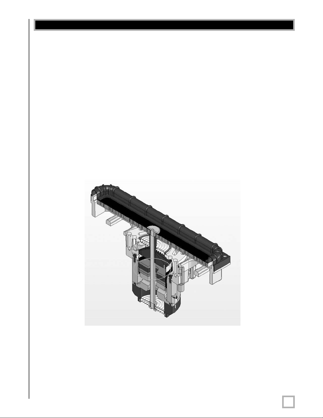
Driver Technology
The SC-IW subwoofer utilizes new and innovative patent-pending driver technology that has been
created specifically for the custom installation market. The SC-IW driver was specially designed
to maximize in-wall subwoofer performance while significantly reducing wall vibration. The driver
uses "dual tandem spider design" along with a pr
an extremely long-throw driver capable of producing very high sound pressure levels. Below is
a cross section of the SC-IW driver.
opriety neodymium motor structure providing
Cabinet Technology
Complimenting the cutting edge technology in the SC-IW driver is the cabinet, again specially
designed for in-wall installations. The SC-IW cabinet wall utilizes a propriety multilayer "sandwich"
material consisting of two 1.0 mm aluminum plates sur
fiberboard (MDF) which is laminated under high pressure to create an extremely rigid cabinet
design that has the density and performance of traditional high end cabinets utilizing 3/4 or 1
inch MDF.
.
www.velodyne.com
rounding 2.5 mm of medium density
SC-IW Installation Manual
1
Page 8
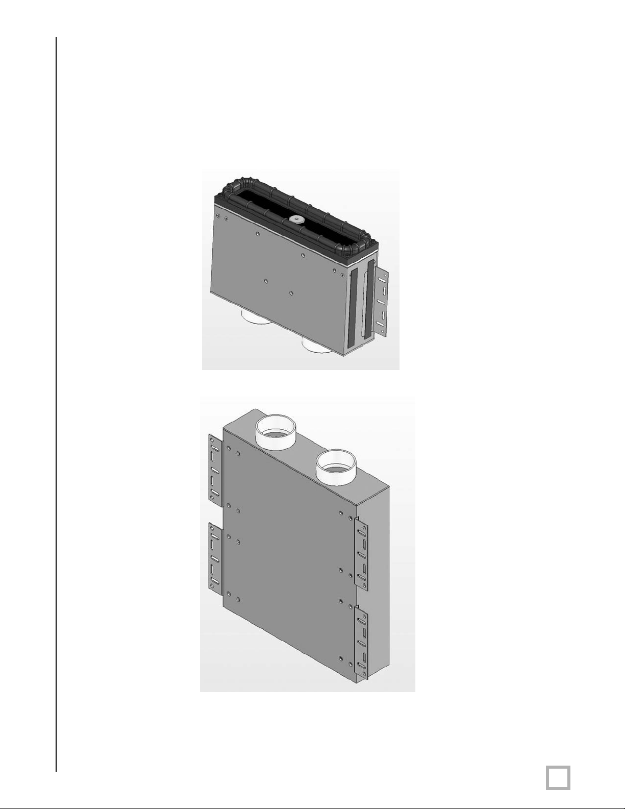
T
he SC-IW consists of two cabinets — the “driver module” and the “back box.” (a.k.a. the
“Enclosure”). Unlike other in-wall products where a back box may be optional, the SC-IW
r
equires both enclosures, unaltered, for every installation. In new construction situations, the
back box is in installed first (for example, at the framing or rough out stage), and the driver
module is installed later in the trim out stage. In retrofit situations both boxes are typically
installed together.
The driver module assembly is shown below. It uses a unique bracing system in that the driver
acts as the "internal bracing structure" for the speaker enclosure.
The in-wall back box contains internal bracing to minimize cabinet flex and wall vibration.
The driver module and the back box ar
supplied hose clamps. This linking system provides the installer the flexibility to either install the
two boxes together in the wall or separately prior to installation.
.
www.velodyne.com
e connected thr
ough two r
ubber conduits, sealed with
SC-IW Installation Manual
2
Page 9

T
he SC-IW comes in two completely separate cartons — the SC-IWBB (Back Box) and the
SC-IWDVR (Driver).
Parts included with the SC-IWBB rough install kit:
• In-wall back box - Qty 1
• Mudring for "retro fit" installation - Qty 1
• Installation manual - Qty 1
• Installation hardware
Parts included with the SC-IWDVR driver module:
• SC-IW driver module - Qty 1
• Clamp ring - Qty 2
• Standard grille - Qty 1
• Designer grille - Qty 1
• Hardware
• Installation manual - Qty 1
Installation Overview
You must first decide how the SC-IW is to be installed — whether new or retrofit installation,
and whether you are using the standard or designer grille. Remember that in all cases the grille
can be painted to match the room’s de´cor.
Consider the following information when deciding how the SC-IW will be installed.
CONSTRUCTION NEW RETROFIT
Standard Benefits: Benefits:
Grille
Designer Benefits: Benefits:
Grille
• Allows pre-installation of the back box Provides easiest servicing for the driver
at minimal risk and expense
• Provides easiest servicing for the driver
• No risk to the subwoofer during this installation
drywall/paint/finish processes
See page 4 for a description of
this installation
• Provides the smallest grille available Provides the smallest grille available
Considerations:
• Must install both back box and driver See page 25 for a description of
cabinet at frame out stage — higher risk this installation
of theft or damage to the subwoofer
• Difficult to service driver as drywall must
be removed to remove driver module
See page 38 for a description of
.
www.velodyne.com
See page 15 for a description of
this installation
SC-IW Installation Manual
3
Page 10
New Construction Installation — Standard Grille
N
ote:This installation process assumes that the installer has access to the open framed 2x4
studded wall with 16 inch spacing. In the event that the stud spacing is larger, an additional
2x4 or other spacer can be used to fill the space between the SC-IW back box and the
neighboring stud.
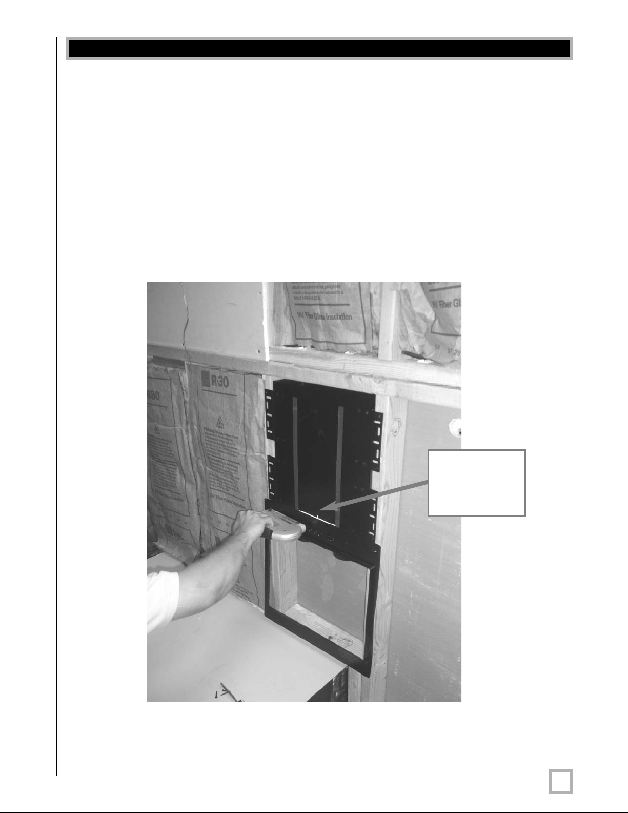
Step 1 - Install Mudring
Unpack the first carton (SC-IWBB) and place the contents on the floor. Remove the mudring
from the packaging. At this time the decision needs to be made about which direction the woofer
will fire (up or down) and therefore where the grille will be located on the wall. Typically the woofer
will fire downwards and the grille will be located near the floor. (Remember to consider
baseboards and other trim work that might be used on the house in this case.) Once you have
decided where to place the grille, staple the mudring to the studs as shown in figure 1.
Align mud
ring to line
on the
back box.
Figure 1: Install Mudring - The back box is used for reference position only — it is installed in the next step.
.
www.velodyne.com
SC-IW Installation Manual
4
Page 11
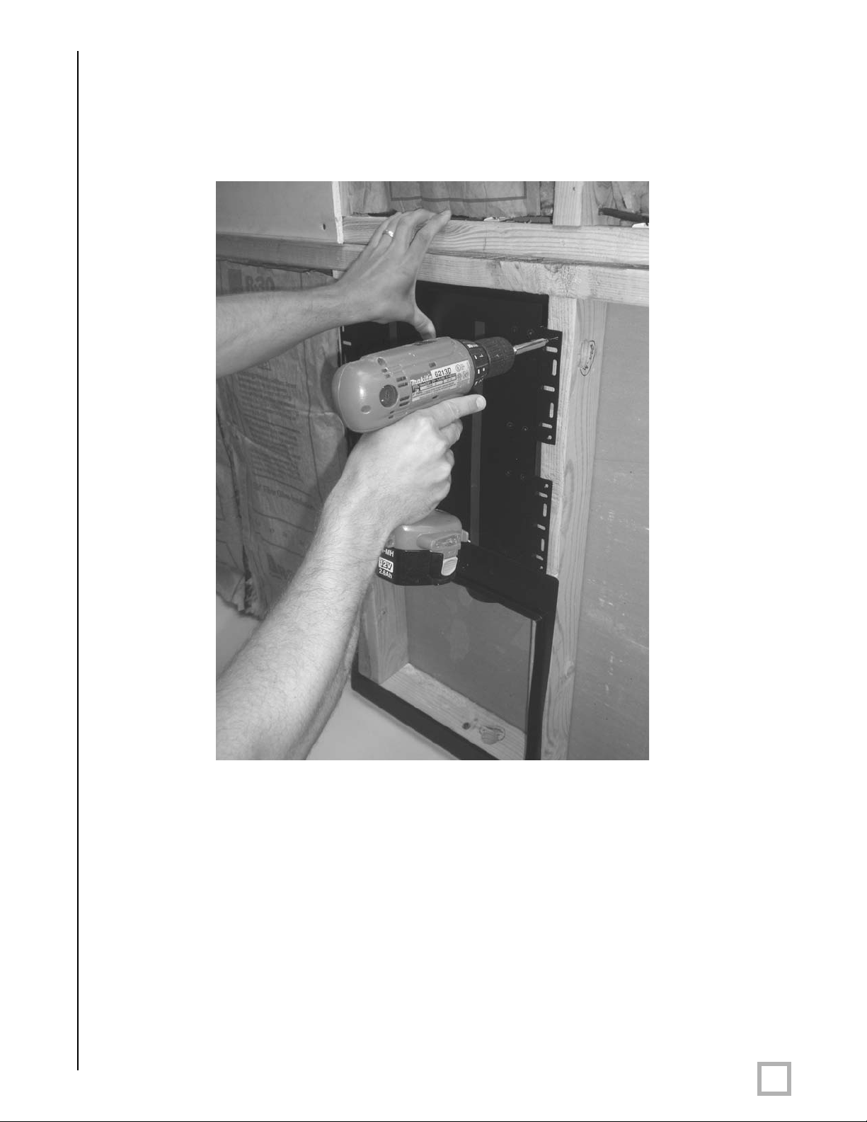
S
tep 2 - Install Back Box
O
nce the mudring is stapled into place, the back box should be installed using eight of the phillips
drive flat head screws included in the package. When installing the back box, the mudring
should be aligned to the white line on the cabinet. Once the mudring and the back box are
aligned, install the back box as shown.
Figure 2: Install Back Box
.
www.velodyne.com
SC-IW Installation Manual
5
Page 12
S
tep 3 - Route Wire
R
oute the wire from the location where the electronics gear is located to where the SC-IW will
be. There is "extra space" between the studs and the back box in the event that the wire has
to pass along the side of the back box to the driver module.
Figure 3: Route Wire
Step 4 - Cover Rubber Couplings
If the installation is not going to be finished right away, Velodyne recommends "taping" or
otherwise “covering” the two connecting tubes to prevent paint, drywall and/or foreign objects
from entering the back box.
.
www.velodyne.com
SC-IW Installation Manual
6
Page 13
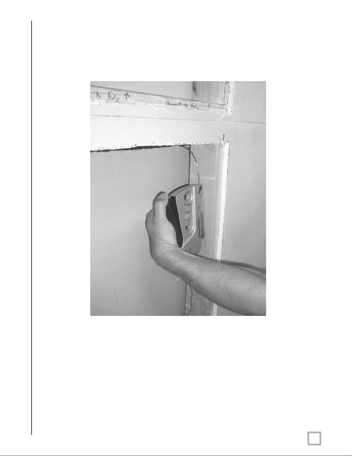
S
tep 5 - Finish Wall
T
he wall can now be finished in a traditional fashion utilizing the appropriate drywall thickness,
standard texturing and finishing methods. Be sure to advise the "finishing” contractors that they
are to drywall up to the edge of the mudring, as the mudring is the place holder for the
installation of the driver module and standard grille.
e 4: Finish Wall
Figur
Note: Steps 6 through 14 presume that you have obtained and are ready to install the
-IWDVR (In-W
SC
Step 6 - Verify Drywall was Properly Installed
Once the wall is finished, the installer must revisit the installation site and verify that the
contractors have properly used the mudring as their guide leaving an opening that is
oximately 16 1/2” x 13 1/4”.
appr
.
www.velodyne.com
all Driver Module).
SC-IW Installation Manual
7
Page 14
S
tep 7 - Remove Mudring
A
t this point, the mudring can be removed. It should be easily removed by "pulling it through"
the drywall opening. After it is removed, discard.
Figure 5: Remove Mudring
.
www.velodyne.com
SC-IW Installation Manual
8
Page 15
S
tep 8 - Place Clamp Rings on Driver Module
R
emove the two clamp rings from the packaging and place a clamp ring onto each of the
bottom edges of the tubes.
Note: The position of the clamp ring is critical. Make sure that the screw section of the ring
is on either side of the tube and not on the front or the back. Please see picture below.
Screw must
face outward
Figure 6: Clamp Ring Placement
.
www.velodyne.com
SC-IW Installation Manual
9
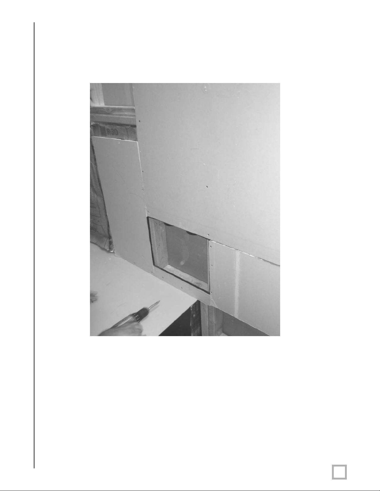
Page 16
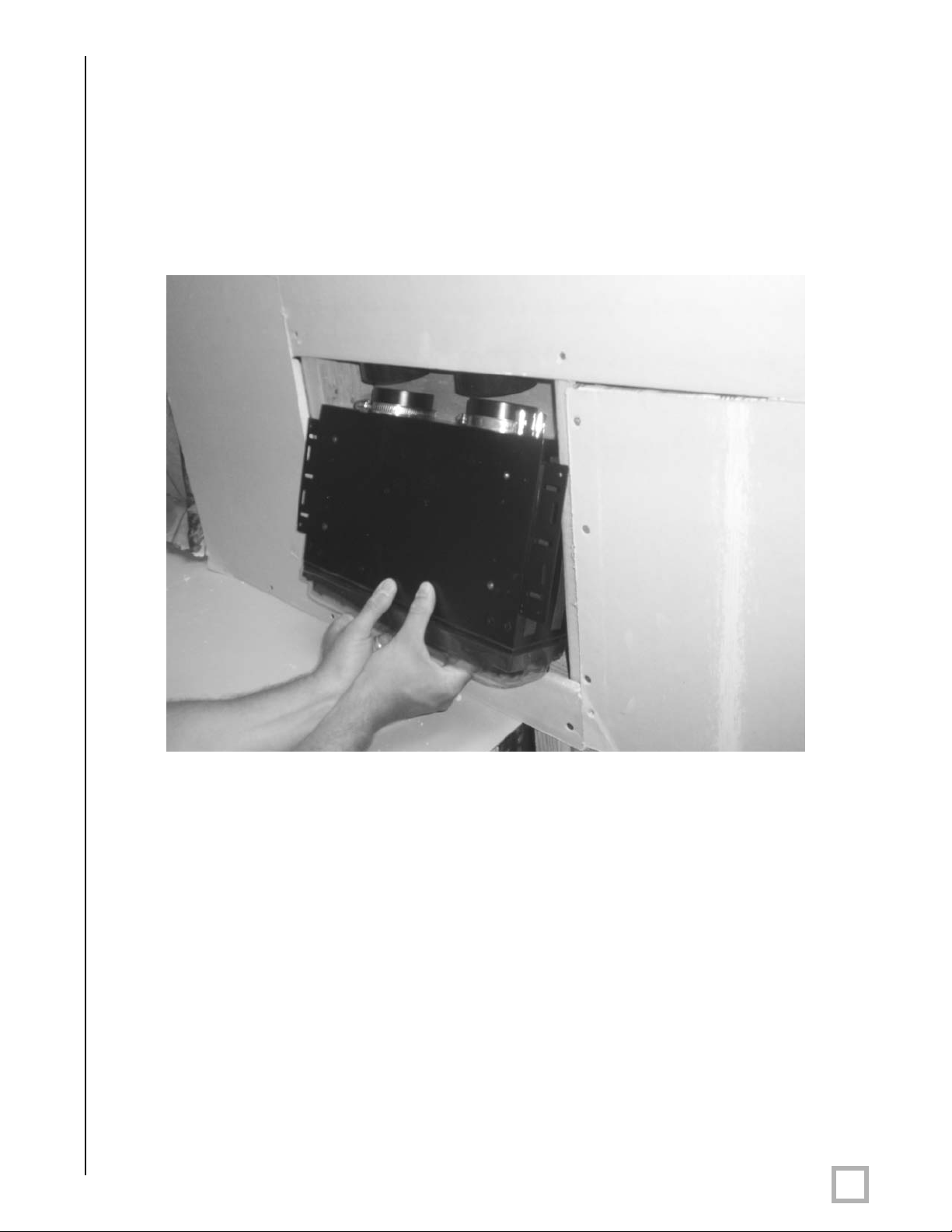
S
tep 9 - Install Driver Module
I
nsert the driver module assembly through the opening left in the wall by the mudring and slide
the plastic tubes onto the two connection tubes The connection tubes should slide all the way
down onto the surface of the driver module assembly. Once the tubes are flush with the driver
module, firmly tighten the two clamp rings to seal the rubber coupling to the plastic tube.
Note: The silicon rubber tubes should slide over the tubes protruding from the driver module
and the clamp rings should slide over the silicon rubber tubes.
Figure 7: Driver Module Installation
Note: It is critical that a good air seal be achieved between the back box and the driver module.
Be sure to properly tighten all clamps. Test the seal by listening to the connection with test
audio material after the install is complete.
.
www.velodyne.com
SC-IW Installation Manual
10
Page 17
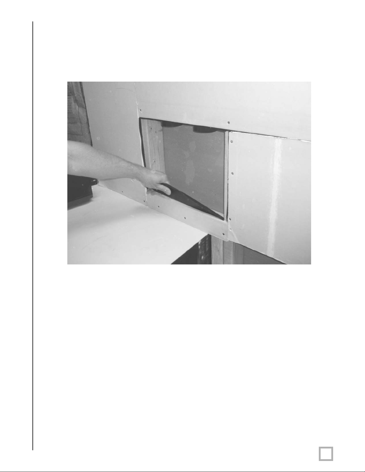
S
tep 10 - Remove Metal Grille
O
btain the standard grille with integrated scoop and remove the metal grille insert, as shown,
in the picture below.
Figure 8: Metal Grille Insert Removal
Note: The grille can be painted to match the de´cor. The supplied paint mask can be used to
paint the grille frame while the metal grille insert can be painted separately.
.
www.velodyne.com
SC-IW Installation Manual
11
Page 18
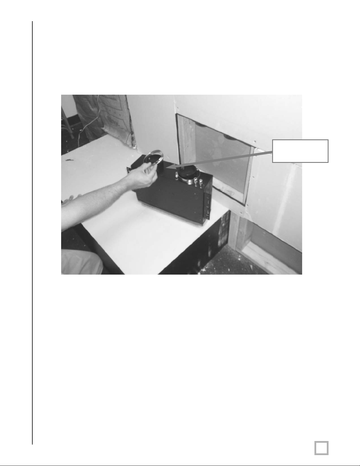
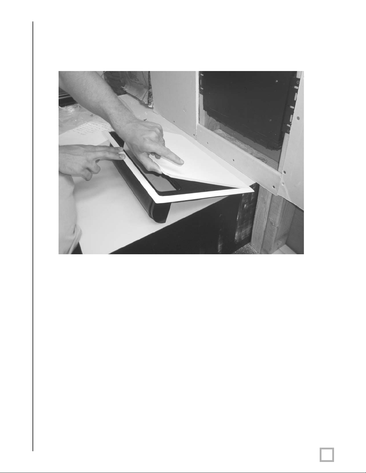
S
tep 11 - Install Grille Frame
I
nstall the plastic grille onto the driver module using the four included machine screws. The
grille hardware should easily be installed into the side of the cabinet. Tighten using the supplied
allen wrench.
Figure 9: Grille Frame Installation
.
www.velodyne.com
SC-IW Installation Manual
12
Page 19

S
tep 12 - Secure Grille
I
nstall two pan head phillips screws (provided) into standard grille into bottom left and bottom
right holes.
Figure 10: Secure Grille
.
www.velodyne.com
SC-IW Installation Manual
13
Page 20

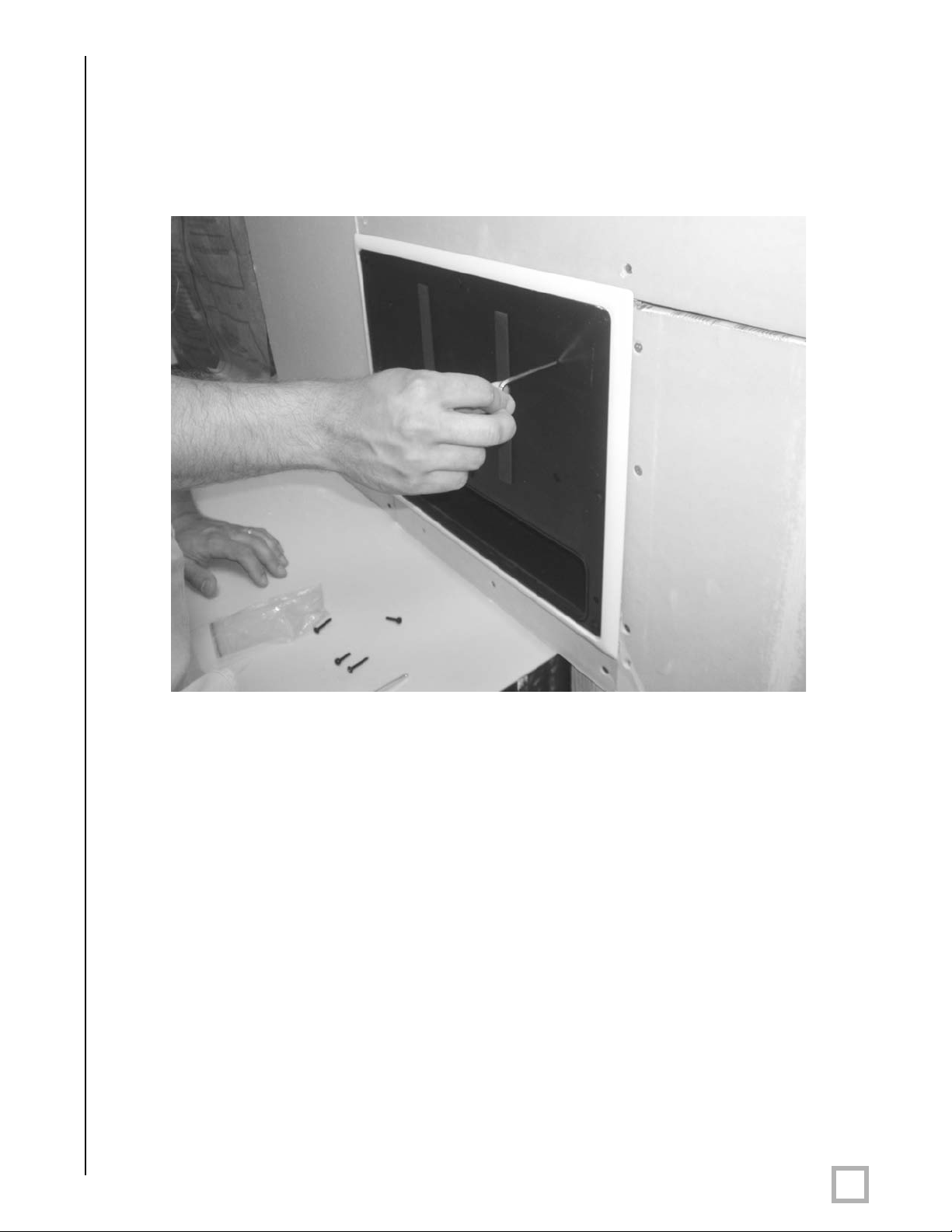
S
tep 13 - Install Metal Grille Insert
Figure 11: Metal Grille Insert Installation
Step 14 - Installation Complete
The installation is complete. Test the
installation with bass audio material
and check for buzzes, rattles, and air
leaks and address accordingly.
.
www.velodyne.com
Figure 12: Completed Installation
SC-IW Installation Manual
14
Page 21

New Construction Installation — Designer Grille
N
ote:This installation process assumes that the installer has access to the open framed 2x4
studded wall with 16 inch spacing. (In the event that the stud spacing is larger, an additional
2x4 or other spacer can be used to fill the space between the SC-IW back box and the
neighboring stud.)
Step 1 - Assemble Cabinet and Driver Modules Together
Remove both the back box and driver modules from the packaging and place them on a clean
surface. Place the back box with the two silicon rubber tubes facing upward. Remove the two
clamp rings from the packaging and place them over the tubes.
Figures 13a and 13b: Cabinet and Driver
Module Assembly
Note: Leave the paint cover on the driver to pr
and finishing process.
.
www.velodyne.com
event damage during the installation, painting
SC-IW Installation Manual
15
Page 22

S
tep 2 - Mark Installation Location
M
easure from the bottom (or top if the SC-IW is to fire upwards) of the designer grille’s lowest
(or highest) position 6 3/8” up along the stud and mark the stud in this location. This location
will determine the bottom edge of the bracket on the driver module.
6 3/8”
e 14: Mark Installation Location
Figur
.
www.velodyne.com
SC-IW Installation Manual
16
Page 23

S
tep 3 - Route Wire
R
oute the wire from the location where the electronics gear is located to where the SC-IW will
be. There is "extra space" between the studs and the back box in the event that the wire has
to pass along the side of the back box to the driver module.
e 15: Route Wire
Figur
.
www.velodyne.com
SC-IW Installation Manual
17
Page 24

S
tep 4 - Secure Subwoofer to Wall
A
fter the location has been determined, securely fasten the subwoofer to the studs. Velodyne
provides 12 screws for this purpose.
Figure 16: Secure Subwoofer
.
www.velodyne.com
SC-IW Installation Manual
18
Page 25

S
tep 5 - Connect Speaker Wire to Subwoofer
C
onnect the previously routed speaker wire to the subwoofer taking care to match the positive
wire to the red terminal and the negative wire to the black terminal. The spring loaded binding
post will hold and secure the wire in place.
Figure 17: Speaker Wire Installation
.
www.velodyne.com
SC-IW Installation Manual
19
Page 26

S
tep 6 - Install Filler Panel
V
elodyne provides an MDF filler panel to fill the distance between the driver module and the
drywall. This filler panel also acts as a guide for the standard grille. The filler panel easily
installs using the four flat head screws and included allen wrench. Be sure to orientate the filler
panel as shown such that the tapered edge faces way from the driver.
Tapered
Edge
Tapered
Tapered
Edge
Edge
Figure 18: Filler Panel Installation
.
www.velodyne.com
Straight
Edge
SC-IW Installation Manual
20
Page 27

S
tep 7 - Install Template Place Holder
C
ut out the part of the installation template that outlines the designer grille. Affix the template
to the studs at the bottom of the filler panel as shown.
e 19: Template Place Holder Installation
Figur
.
www.velodyne.com
SC-IW Installation Manual
21
Page 28

S
tep 8 - Finish Wall
T
he wall can now be finished in a traditional fashion utilizing the appropriate drywall thickness,
standard texturing and finishing methods. Be sure to advise the "finishing” contractors that they
are to drywall up to the edge of the template, as the template is the place holder for the
installation of the designer template grille.
Figure 20: Finish Wall
Step 9 - Verify Drywall was Properly Installed
Once the wall is finished, the installer must revisit the installation site and verify that the
contractors have properly used the mudring as their a guide leaving an opening that is
oximately 17 1/2” x 4 1/2”.
appr
.
www.velodyne.com
SC-IW Installation Manual
22
Page 29

S
tep 10 - Install Designer Grille
R
emove metal grille insert from the plastic grille and insert into opening into the wall. The grille
should then be affixed to the studs using the four included phillips drive pan head screws.
Figures 21a and 21b: Designer Grille Installation
.
www.velodyne.com
SC-IW Installation Manual
23
Page 30

S
tep 11 - Install Metal Insert into Plastic Grille Frame
Figure 22: Metal Insert Installation
Step 12 - Finished Grille
Figur
e 23: Finished Grille Installation
.
www.velodyne.com
SC-IW Installation Manual
24
Page 31

Retro-Fit Installation with Designer Grille
S
tep 1 - Decide on Subwoofer Orientation and Grille Location
The first decision for a retrofit installation is which way the subwoofer will face (up or down),
and therefore where the designer grille will be located on the wall (near the floor or ceiling).
Once the location is decided, locate the 2x4 studs, spaced 16 inches on center. After the
general area of the studs is located, determine the exact location of the studs as detailed in
the picture below. There are many methods to do this. Shown is the use of a “drywall saw”
used horizontally to find the edge of each stud.
.
Figure 24: Subwoofer Orientation and Grille Location
.
www.velodyne.com
SC-IW Installation Manual
25
Page 32

S
tep 2 - Cut Out Drywall Per Template
O
nce the studs have been located, place the supplied designer grille template on the wall. After
the template is secured to the wall with either staples or tape, score the drywall along the lines
as detailed on the template.
Figure 25: Cut Out Drywall Per Template
Note: Two templates are provided, one for the designer grille and one for the standard grille.
Be sure to use the correct template!
.
www.velodyne.com
SC-IW Installation Manual
26
Page 33

S
tep 3 - Remove Drywall After it is Scored
A
fter the drywall is scored, remove the template and the drywall as indicated. The cutout after
removal is shown in figures 26a and 26b.
Figures 26a and 26b: Drywall Removal
.
www.velodyne.com
SC-IW Installation Manual
27
Page 34

S
tep 4 - Run Speaker Wire from Amplifier Location to In-Wall Subwoofer
R
oute the wire from the location where the electronics gear is located to where the SC-IW will
be. There is extra space between the studs and the box in the event that the wire has to pass
along the side of the back box to the driver module.
Figure 27: Speaker Wire Installation
Note: 14 A
.
www.velodyne.com
WG or lar
ger wire is recommended.
SC-IW Installation Manual
28
Page 35

S
tep 5 - Assemble Cabinet and Driver Modules Together
R
emove both the back box and driver modules from the packaging and place them on a clean
surface. Place the back box with the two silicon rubber tubes facing upward. Remove the two
clamp rings from the packaging and place them over the tubes.
Figures 28a and 28b: Cabinet and Driver Module Assembly
Note: Leave the paint cover on the driver to pr
and finishing process.
.
www.velodyne.com
event damage during the installation, painting
SC-IW Installation Manual
29
Page 36

S
tep 6 - Mark Installation Location
M
easure from the bottom of the cutout 6 3/8” up along the stud and mark the stud in this
location. This location will determine the bottom edge of the bracket on the driver module.
6 3/8”
e 29: Mark Installation Location
Figur
.
www.velodyne.com
SC-IW Installation Manual
30
Page 37

S
tep 7 - Install Subwoofer into Opening
A
fter the in-wall subwoofer assembly is complete, and the mounting position marked, orient the
assembly inside the wall. In this installation example we have decided to face the unit downward.
It is critical at this point that the top of the cabinet module is aligned with the top of the cutout
and that the brackets are 6 3/8” from the bottom of the cutout.
Figure 30: Subwoofer Installation
6 3/8”
.
www.velodyne.com
SC-IW Installation Manual
31
Page 38

S
tep 8 - Secure Subwoofer to Wall
A
fter the location has been determined, securely fasten the subwoofer to the studs. Velodyne
provides 12 screws for this purpose.
Figure 31: Secure Subwoofer
.
www.velodyne.com
SC-IW Installation Manual
32
Page 39

S
tep 9 - Connect Speaker Wire to Subwoofer
C
onnect the previously routed speaker wire to the subwoofer taking care to match the positive
wire to the red terminal and the negative wire to the black terminal. The spring loaded binding
post will hold and secure the wire in place.
e 32: Connect Speaker Wire
Figur
.
www.velodyne.com
SC-IW Installation Manual
33
Page 40

S
tep 10 - Install Filler Panel
V
elodyne provides an MDF filler panel to fill the distance between the driver module and the
drywall. This filler panel also acts as a guide for the designer grille. The filler panel easily installs
using the four flat head screws and included allen wrench. Be sure to orientate the filler panel
as shown such that the tapered edge faces way from the driver.
Tapered
Edge
Tapered
Edge
Figure 33: Filler Panel Installation
Straight
Edge
Taper
Edge
ed
.
www.velodyne.com
SC-IW Installation Manual
34
Page 41

S
tep 11 - Install Drywall Above Filler Plate
A
fter the filler plate is secured to the driver module, install a replacement piece of drywall above
the filler plate in the opening. This drywall should be securely fastened to the studs using
drywall screws.
Figure 34: Drywall Installation
Step 12 - T
After the SC--IW is installed into the wall, the wall should be taped, textured, blended and then
painted to match the existing wall. Note the grille can also be painted to match the de´cor.
Note: The paint cover should be remain on the driver until this step is complete.
.
www.velodyne.com
ape, Mud, T
exture and Paint Wall
SC-IW Installation Manual
35
Page 42

S
tep 13 - Install Designer Grille
R
emove metal grille insert from the plastic grille and insert into opening into the wall. The grille
should then be affixed to the studs using the four included phillips drive pan head screws.
Figures 35a and 35b: Designer Grille Installation
.
www.velodyne.com
SC-IW Installation Manual
36
Page 43

S
tep 14 - Install Metal Insert into Plastic Grille Frame
Figure 36: Metal Insert Installation
Step 15 - Finished Grille
Figure 37: Finished Grille Installation
.
www.velodyne.com
SC-IW Installation Manual
37
Page 44

Retro-Fit Installation with Standard Grille
S
tep 1 - Decide on Subwoofer Orientation and Grille Location
The first decision for a retrofit installation is which way the subwoofer will face (up or down),
and therefore where the standard grille will be located on the wall (near the floor or ceiling).
Once the location is decided, locate the 2x4 studs, spaced 16 inches on center. After the
general area of the studs is located, the installer needs to determine the exact location of the
studs as detailed in the picture below. There are many methods to do this. Shown is the use of
a drywall saw used horizontally to find the edge of each stud.
Figure 38: Subwoofer Orientation and Grille Location
.
www.velodyne.com
SC-IW Installation Manual
38
Page 45

S
tep 2 - Cut Out Drywall Per Template
O
nce the studs have been located, place the supplied standard grille template on the wall. After
the template is secured to the wall with either staples or tape, score the drywall along the lines
as detailed on the template.
Figure 39: Cut Out Drywall
Note: Two templates are provided, one for the designer grille and one for the standard grille.
Be sure to use the correct template!
.
www.velodyne.com
SC-IW Installation Manual
39
Page 46

S
tep 3 - Remove Drywall After it is Scored
A
fter the drywall is scored, remove the template and the drywall as indicated. The cutout after
removal is shown in figures 40a and 40b.
Figures 40a and 40b: Drywall Removal
.
www.velodyne.com
SC-IW Installation Manual
40
Page 47

S
tep 4 - Run Speaker Wire from Amplifier Location to In-Wall Subwoofer
R
oute the wire from the location where the electronics gear is located to where the SC-IW will
be. There is extra space between the studs and the box in the event that the wire has to pass
along the side of the back box to the driver module.
Figure 41: Speaker Wire Installation
.
www.velodyne.com
SC-IW Installation Manual
41
Page 48

S
tep 5 - Assemble Cabinet and Driver Modules Together
R
emove both the back box and driver modules from the packaging and place them on a clean
surface. Place the back box with the two silicon rubber tubes facing upward. Remove the two
clamp rings from the packaging and place them over the tubes.
Figures 42a and 42b: Cabinet and Driver Module Assembly
Note: Leave the paint cover on the driver to pr
and finishing process.
.
www.velodyne.com
event damage during the installation, painting
SC-IW Installation Manual
42
Page 49

S
tep 6 - Mark Installation Location
M
easure from the bottom of the cutout 5 3/8” up along the stud and mark the stud in this
location. This location will determine the bottom edge of the bracket on the driver module.
5 3/8”
e 43: Mark Installation Location
Figur
.
www.velodyne.com
SC-IW Installation Manual
43
Page 50

S
tep 7 - Install Subwoofer into Opening
A
fter the in-wall subwoofer assembly is complete, orientate the assembly inside the wall. In this
installation example we have decided to face the unit downward. It is critical at this point that
the top of the cabinet module is aligned with the top of the cutout and that the brackets are
5 3/8” from the bottom of the cutout.
Figure 44: Subwoofer Installation
5 3/8”
.
www.velodyne.com
SC-IW Installation Manual
44
Page 51

S
tep 8 - Secure Subwoofer to Wall
A
fter the location has been determined, securely fasten the subwoofer to the studs. Velodyne
provides 12 screws for this purpose.
Figure 45: Secure Subwoofer
.
www.velodyne.com
SC-IW Installation Manual
45
Page 52

S
tep 9 - Connect Speaker Wire to Subwoofer
C
onnect the previously routed speaker wire to the subwoofer taking care to match the positive
wire to the red terminal and the negative wire to the black terminal. The spring loaded binding
post will hold and secure the wire in place.
e 46: Speaker Wir
Figur
.
www.velodyne.com
e Installation
SC-IW Installation Manual
46
Page 53

S
tep 10 - Install Filler Panel
V
elodyne provides an MDF filler panel to fill the distance between the driver module and the
drywall. This filler panel also acts as a guide for the standard grille. The filler panel easily
installs using the four flat head screws and included allen wrench. Be sure to orientate the filler
panel as shown such that the tapered edge faces way from the driver.
Tapered
Edge
Tapered
Tapered
Edge
Edge
Figure 47: Filler Panel Installation
.
www.velodyne.com
Straight
Edge
SC-IW Installation Manual
47
Page 54

S
tep 11 - Install Drywall Above Filler Plate
A
fter the filler plate is secured to the driver module, install a replacement piece of drywall above
the filler plate in the opening. This drywall should be securely fastened to the studs using
drywall screws.
Figure 48: Drywall Installation
Step 12 - Tape, Mud, Texture and Paint Wall
After the V
blended and then painted to match the existing wall. It is not required to finish the filler plate
as it will be removed in the next step.
Note the grille can also be painted to match the de´cor. The supplied paint masks can be used
to paint the grille frame while the metal grille insert can be painted separately.
Note: The paint cover should be remain on the driver until this step is complete.
.
www.velodyne.com
elodyne subwoofer is installed into the wall, the wall should be taped, textured,
SC-IW Installation Manual
48
Page 55

S
tep 13 - Remove Metal Grille
R
emove the filler plate. Obtain the standard grille with integrated scoop and remove metal grille
insert, as shown, in the picture below.
Figure 49: Metal Grille Insert Removal
.
www.velodyne.com
SC-IW Installation Manual
49
Page 56

S
tep 14 - Install Grille Frame
I
nstall the plastic grille onto the driver module using the four included machine screws. The
grille hardware should easily be installed into the side of the cabinet. Tighten using the supplied
allen wrench.
Figure 50: Grille Frame Installation
.
www.velodyne.com
SC-IW Installation Manual
50
Page 57

S
tep 15 - Secure Grille
I
nstall two pan head phillips screws (provided) into standard grille into bottom left and bottom
right holes.
Figure 51: Secure Grille
.
www.velodyne.com
SC-IW Installation Manual
51
Page 58

S
tep 16 - Install Metal Grille Insert
Figure 52: Metal Grille Insert Installation
Step 17 - Installation Complete
The installation is complete. Test the
installation with bass audio material and
check for buzzes, rattles, and air leaks
and address accordingly.
The grille can also be painted to match
the de´cor if desired.
.
www.velodyne.com
Figure 53: Completed Installation
SC-IW Installation Manual
52
Page 59

Other Velodyne Subwoofer Products
110V
DD Series
DD-10
DD-12
DD-15
DD-18
Digital Drive 1812
Signature Edition
DLS-R Series
DLS-3500R
DLS-3750R
DLS-4000R
DLS-5000R
DPS Series
DPS-10
MiniVee™
SMS™-1
SPL-R Series
SPL-800R
SPL-1000R
SPL-1200R
-1500R
SPL
VRP Series
VRP-1000
VRP-1200
VX Series
VX-10
230V
DD Series
DD-10
DD-12
DD-15
DD-18
Digital Drive 1812
Signature Edition
CHT-R Series
CHT-8R
CHT-10R
CHT-12R
CHT-15R
SMS™ -1
SPL-800i
SPL-R Series
SPL-800R
SPL-1000R
SPL-1200R
-1500R
SPL
DPS-12
.
www.velodyne.com
SC-IW Installation Manual
53
Page 60

LIMITED WARRANTY
VELODYNE ACOUSTICS, Inc. (“VELODYNE”) warrants all electronics and powered subwoofers for a period of two
years and full range speakers for a period of five years. All VELODYNE products have a warranty from the date of
purchase against defects in materials and workmanship subject to the following conditions:
1. VELODYNE is not responsible for defects which result from the use of an amplifier or controller other than
the one originally supplied with the unit (subwoofer) or defects which result from modifications or repairs
made by any component of the system by anyone other than a VELODYNE factory authorized
service representative.
2. This warranty is void if any repairs or service covered by the terms of this warranty are made to any
component of the system by anyone other than a VELODYNE factory authorized service representative.
3. VELODYNE is not responsible for damage caused by accidents, abuse, misuse, natural or personal disaster
or unauthorized modification. The VELODYNE products are not intended for professional or commercial use
and VELODYNE is not responsible for damage resulting from such use.
4. The VELODYNE product warranty is limited to units that are purchased from authorized VELODYNE dealers
and finalized within authorized dealer locations.
5. This warranty is nontransferable under any condition.
TO OBTAIN SERVICE
Information regarding service may be obtained from the dealer from whom you purchased the unit, or by contacting
VELODYNE customer service. Warranty service must be performed by a VELODYNE factory authorized service
representative within the warranty period set forth above. If VELODYNE determines the unit is defective, VELODYNE
will, at VELODYNE’s option, repair or replace the product at no charge if the product is forwarded prepaid to a factory
authorized service representative. Products forwarded to the factory authorized service representative should be
shipped securely and properly packaged, insured and freight prepaid.
63-SCIWBB REV B SEP06
.
www.velodyne.com
Velodyne Acoustics, Inc.
Morgan Hill, CA 95037
408.465.2800 voice
408.779.9208 service fax
Service E
Product E
Technical E
345 Digital Drive
408.779.9227 fax
.velodyne.com
www
-mail: service@velodyne.com
-mail: help@velodyne.com
-mail: techhelp@velodyne.com
SC-IW Installation Manual
54
 Loading...