

Page 1
"Ifyou k
"... it's safe to say that when it comes to woofin , done right,
Velodyne's bigger models are probably the safest bet there is."
"... we
this jun ior varsity Velodyne."
now
subwoofers, you
just
sat there marvelling at the
know
about
sheer
Veladyne."
power
and
majesty of
~
8
10/1012XII
-Corey Greenberg
Home Theater Technology
Face Off: Comparison of five subwoofers
Model Tested: VA-1012X
Velodyne
1070 Commercial St. Suite #101
Web Site: http//www.velodyne.com
E-mail: velodyne@earthlink.net
/F
ebruary 1995
Aco
ustics, Inc.
San Jose
408.436.7270 voice
408.436.7276 fax
,'
CA 95112
Owner's Ma
Velod
AudiolVideo SubwQofer
ne
nu
System
al
@ Printed on recycledpaper.
Page 2
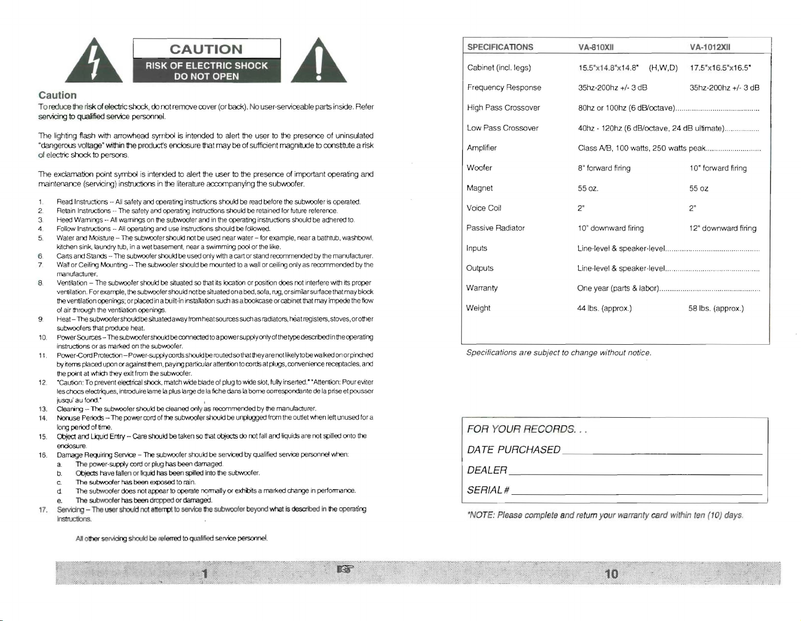
SPECIFICAnONS VA-810XII
VA·1012X1I
A
IIiiiiII
•• • • •
A
Caution
To reduce the risk ofelectric shock,00 not r
se rvicing
toqualified service
Th e lighting
"dangerous
01
electric shock to pe
The exclama
maintenance (servicing) instructions in theliterature
1. ReadInstructions -- Allsafetyandooera
2. RetainInstructions--Thesafetyandoperating inst
3. HeedWamings .- Allwamingsonmesubwooteraro intheoperatinginstructions shouldbe adheredto.
4. Follow Instructions --Alloperatingard use instructionsshouldbe followed.
5. Waferand Moisture - The
6. carts and Stands--Thesubwoclershouldbeusedonly
7. Wallor Ceiling Mounting-- The subv.oofershouldbe mountedtoa wallorceilingonlyas recommended by the
8. Ventilation- Thesubv.ootershouldbe situatedso
9. Heat- Thesubv.oofershouldbes;tuatedawayfromheatsourcessuchasradiators,beatregisters,stoves,orother
10 Power
11.
12. "caution:To preventelectrical
13. Clearing -- 'The subv.oofer should be cleaned only as recommerd ed by
14.
15. Olject and
16. DamageReqJiringService--
17. 5ervdrg - The
flash with arrowhe ad symbol is intended to alert the user to the presence of uninsulated
voltage"'Nithin the product's enclosure that
tion point symbol is intended to alert the
kitchensink, laundrytub,in a wet basement,neara swimming
mamJlacturer.
verrtilation.For
theventilationqJenings;orplacedina
of air
subwoofers that produce heat.
ructioflS
inst
Power
by
~enns
thepointatwhichtheyexitfrom thesubwoofer.
leschocs
jusqu'
Non..ise
IorYJ
enclosure.
a.
b.
c. The subwoolerhas been exposed to rain.
d. The su
e.
InstIUCllons.
exarrote, thesobwoolershouldro tbesituatedona
lt1rou
gh the
Sources--Thesubv.oofershouldbeconnectedtoapowersupplyonlyofthetypedescribed intheoperating
or as marked on the subwooler.
~ord
P
rotectioo
placeduponoragainstmern,
e1
ectriques,introduirelame Iaplus large delafichedans Iabornecorrespondante de la prise el pousser
au fond:
Periods--Thepowercordofthe
pe
roo
of time.
lXlud
The power-supply cordorplug has been damaged.
OJjects havefallen or
b'M:xJf
The subv.oolerhas beendrcpped or damaged.
personnel
rsons.
subwoote
ventilation
ooenros.
- Power-supplycordsshouldberoutedsothattheyarero tlikelytobewalkedonorpinched
shod< , matchw'de bladeof plug to w'de slot, fUllyinserted." "A
Er1Iry
- careshouldbe takenso thatotiects dorot falland liquidsare rot spilledonto the
Thesebwootershould be servicedby qualified servicepersonnelwhen:
lQJ
er
does
rot aroea r to operate m rmally or
use
rsrouklnot
emov
e cover (or
.
trq
instructionsshouldbereadbeforethesubwcoferis operated.
rshouldnotbe used near water - for example,near a bathtub,washbowl,
built-in
iflStallationsuchasabookcaseorcabinetthatmayimpedethe flow
paYing
particularatterrtiontocordsatplugs,convenience
suowoot
idhas
been
spilled into thesubwoofer.
atterrpt
toservicethe
back
). Nouser-serviceablepartsinside. Refer
may
be of sufficient magnibJde tocons1itule a risk
user
to the pre
accomp
anying the subwoo fer.
ructons
shouldbe retainedfor futurereference.
witha cartorstand recommerdedby themanufacturer.
mat
~
s
locationor poston does not interfere
er shouldbeunpluggedfromtheoutletwtlen leftunusedfora
Slbwooler
serc
e of important operating and
pool or the like.
bed
,sofa,rug,orsimilarsurfacethatmayblock
receptacles,
tterrt
lt1
e manufacturer.
exl1iJit
s a marked charge in performance.
beycrowhat is
descrt>ed
in the
'-\1th ~ proper
ion: Poureviter
opern
and
ting
Cabi net (incl.
Freq
High Pass C
L
ow
Amplifier
oofer
W
Ma
gnet
Voice Coil 2"
Pa
ssive
Inpu ts
Ou tputs
W arr
Weight
Specifications are subject to change without notice.
uency
Respon
Pas s Cros
Radiator
anty
leg
s) 15.5' x 14.8' x1
rossove
sover
se
r
35hz-2
80hz or 100hz
40hz - 120 hz (6 dB/
Cla ss
8" f
orwar
55 oz.
10' do
Line-level
Line-le vel
One year (parts
44 Ibs. (approx.)
4.8'
(H
,W
00hz +/-3 dB
(6
dB/oct
ave) ..
octave
AlB ,
100
watts,
250
d firing 10' forw ard firing
wnw
ard firing 12" down ward firin g
&
speaker
-level.
&
speak
er-level .....
& l
abor)
17.5' x16.5 ' x16
,D)
35hz-200hz
, 24
dB
ulti
watts
peak
55
2"
58 Ibs. (approx.)
mate)
0l
.5'
+/- 3 dB
....
FOR YOUR RECORDS. . .
DATE PURCHASED _
OEALER _
SERIAL# _
'NOTE: Please completeandreturnyour warranty card withinten(10) days.
..
..
All other servicing shook! be referred to quafifiedservice
personnel
.
Page 3

several minutes when there is no longer any signal at the inputs.
If you plan to leave the \{A-810/1012XII unused for an extended
period of time,we recommendthat you turnoff the unitby the master
power switch on the rear panel .
Troubleshooting & Service
Before seeking service for
re-check all systems. Following is a simple troubleshooting guide to
assist you.
1. Verify unit is plugged in and power outlet used is active.
power
2. Is
3. Is auto turn on/off set properly?
4. Is unit receiving an input signal from your source?
5. Have all controls on subwoofer (volume, crossover, phase,
etc.) been properly set?
6. If unit has been running at high levels, one of the protection
circuits may be engaged.
If the protection circuitry is active, the unit may cycle on and off until
operating parameters return to normal. Under more serious conditions , the unit may shut off comp)etely. Normal operation will return
upon cooling, but you may be required to turn the power off and then
on again to reset the unit.
The following conditions require service by a qualified technician :
1. The power cord has become damaged.
2. The unit does not appear to operate normally or exhibits a
marked change in performance.
3. The unit has been exposed to water.
4. Some part of the cabinet or circuitry is physically damaged.
Thank
switch on?
Has
the built-in amplifier overheated?
Has
the speaker's voice coil started to heat up?
you
for
your
VA-810/1012XII subwoofer, please
purchasing a Velodyne!
Congratulations!
Cong ratulations on your purchase of a Velodyne VA-810/1012XII
subwoofer system. This system represents the state of the art in
accurate low frequency reproduction. Read and follow the instructions below to insure safe and proper system operation.
Warning!
To
prevent
rain or moisture . To
enclosure or
equipment
refer
Prior to installation
Please unpack the system carefully. Remove all staples used to
seal the carton as they can scratch the cabinet. Please save the
carton and all packaging materials for future use. Record the serial
number
reference.
fire or shock hazard, do
avoid
electrical shock, do not open
amp
chassis cover. Please observe all warnings on the
itself. There are no user serviceable
all
service questions to
in the space provided on the warranty card for future
your
not
expose this equipment to
pans
inside . Please
authorized Velodyne dealer.
speaker
Product Features & Controls
• Built-in 100 watt (RMS) power amplifier
• Adjustable (40 to 120hz) low-pass crossover with bypass option
• Selectable (80 or 100hz) high-pass crossover
• Line-level inputs
• Speaker-level inputs
tions
• Signal sensing auto turn on/off with bypass option
• Variable volume control
• selectable phase control (0 or 180 degrees)
• Detachable power cord (available on some versions)
• Magnetically shielded for video use
• Dual staggered low-pass crossover; 12dB/octave initial, 24dB/
octave ultimate
• Gain compression circuit to protect woofer from over excursion
• Input overload protection
& outputs
& outputs with 5 way binding post connec-
Page 4

Installation
Yournew VA-810/1012XIIsubwoofersystem provides for a number
of installation options. Read all the installation information below in
order to determine which installation option is best for your system.
Remember to perform all installation procedures with system
powe r turned off.
Inputs
Your new VA-810/1012XIIsubwoofer isequippedwith both speakerlevel and line-level inputs. Use the LINE-IN jacks when connecting
your subwoofer to a pre-amp, signal processor, or line-level crossover.
The
FROM AMPLIFIER jacks connect directly to the speaker
outputs of a integrated amplifier or receiver. Your amplifier section
will notice no additional loading effects when you use these inputs
because of their high impedance.
Note
00
not use both LINE-IN
neously.
Volume control
This control allows you to balance the output from the subwoofer to
the main speakers in your system. This contr.olshould be set to
achieve similar volume level from both the main speakers and
subwoofer.
and
FROM
AMPLIFIER
inputs simulta-
same channel.
Keep in mind that frequency response and output level carl be
drastically influenced by placement depending on the acoustic
properties of the listening room. Ty pically the VA-810/1012XII will
sound louder when placed next to a wall or in a corner.
Caution!
The VAseries sub woofers have amplifiers built into the cabinet. 0 0
not
place the cabinet next to sources of heat such as furnace
registers, radiators, etc. The
power
cord should be routed in 'Such
a way that it will not be walked on, pinched, or compressed in any
way.
Regardless of whereyou install your VA-81 0/1012XIIsubwoofer, it
must remain in an upright position (passive radiator facing downward) . Using, shipping, or otherwise storing the VA-810/1012XII
subwoofer in any other position for an extended period of time may
result in damage to the unit not covered by warranty.
The
VA-810/1012XII Subwoofer is magnetically shielded to reduce
magnetic emission from its cabinet to increase the number of
possibl e locations available for placement. However, this shielding
maynot beadequatefor all installations.Certaintypes of televisions
are particularly sensitive to stray magnetic fields . If your television
produces distorted colors after installation of your VA-810/1012XII
subwoofer, simply increase the distance between your television
and the VA-810/1012XII until normal color and operation is returned.
Low-pass crossover
Both sets of inputs sum the left and right channels together and the
resulting signal is passed through an adjustable low-pass crossover
before being amplified. The crossover control allows you to adjust
the upper limit of the subwoofer's frequency response from 40 to
120 hz. The subwoofer's response will begin rolling off above the
frequency you set this control to.
You should set the crossover frequency to obtain a smooth and
seamless transition from the subwoofer to the main speakers in
your system.
frequency output.
Ifyour main speakersaresmaller units withlimited low
~
/I)
U
may wish tochoose a higherfrequency (such
Care
Do not use any harsh detergents or chemicals to clean the cabinet.
Abrasives, detergents, or clean ing solutions may damage the finish
on the cabinet. We recommend using a damp cloth to clean the
cabinet.
During normal conditions, the VA-810/1012X II subwoofer may be
left on continuously without any problems. The unitisequipped with
a signal sensing turn on/off that will automatically turn on the unit
when a signal is prese nt at the inputs and turn off the unit after
of
oot
er
Page 5

Figu re 2 : Installation using speaker-level (from amplifier) inputs
....
~
,6E\ . -
'
,'QW
:-t
.
.. E:::H
,,--
w
'
- -'-.-l~O @~r-""'
iHiHi)
~
'.
MA IN
(s p ea ke r
INTEGRATED
:::J.
11Th.
-
-.'0JI--T T
....
~~:
Ii)
- - -
OUTPUT
-leve
AMP I
[lID]
;;
~
o
l
~
"'
_ . ---'
(iHi)
Ii)
@@
~,
RECE
S
l )
IVER
li
SATE
.
ACl.
@
,!n
LLITE
~
V~od
- -- -- -
~~I:':.
SPEAKERS
yn
':.
-::.r:="
___ I
as 100-120hz) than you would with larger speakers which have
greaterlow frequency output. With larger speakers, you mighi start
e
with this control set lower, such as 80hz.
A bypass switch is also provided if you wish to use an external
crossover. If you are not using an external crossover, we recommend that you use the one provided within the unit for optimum
performanc e.
Phase adjust
This control allows you the ability to compensate for having the
subwoofer in a different location than the main speakers. Ideally,
you will have the sound from the subwoofer reach the listening
position the same time as the sound from the main speakers,
However,ifthe distance from the listening position to the subwoofer
and thedistance from listeningpositionto themain speakers differs ,
the sound from each will reach your ears at a different time.
This control allows the signal to be delayed 180 degrees so the
output of the subwoofer will blend in to that of your main speak ers
without any cancellation.
ment
Interconnect cables
When installing your VA-810/1012XII using the line-level inputs/
outputs , you should use standard shielded phono cables. Always
keep the lines as short as practical to minimize noise.
When using the speaker-level inputs/outputs, use the same quali ty
speaker cable to your subwoofer as you run to your satellites.
'/ac
em
ent
The VA-81 0/1012XII operates at very low frequencies which are
primarily non-directional. While it is recommended that the subwooferbe placed on the same plane as the satellite speakers, room
and system conditions often dictate otherwise. See your dealer for
help in placement.
' When using a pair of VA-810/1012XII subwoofers in stereo, it is
preferable to place each subwoofer adjacent to the satellite of the
Auto
turn
on
switch
The auto turn on switch allows the user to bypass the auto turn on
function ifdesired. When set in the "auto"mode with main poweron,
the VA-1008/121Owillturn itself on when an input signal is present.
If no signal is present, after several minute s the unit will shut itself
off. When set in the "on " mode, the auto turn on/off function is
bypassed and the unit will be on whenever the main power switch
is on.
High
pass
crossover
This switch selects the frequency for the high pass crossover. This
crossover is functional on both line and speaker-level outputs.
Smaller speakers with limited low frequency output may prefer the
higher 100hz se
them. Larger speakers with greater low frequency output may be
able to handle the 80hz setting without strain.
Power
The masterpowerswitch is located on the right half ofthe unit. This
rocker style switch isthe main
switch
lli
switch
ng which will reduce the low frequencies sent to
onloff for the unit. This switch should
con tin ued.
..
Page 6

be set to position 1 for on (up), 0 for off (down).
ac
hable
Det
Allows for easy replacement should the original be damaged.
power cord
(available on some versions)
amplifier and speaker. Combining both an external crossover and the
one internal to the subwoofer may result in low output and increased
noise. In these cases,to optimizeyour subwoofer performance you
should bypass the internal crossover in your
Velodyne subwoofer .
Line-lev
Figure 1 shows connection to a pre-amplifier's main outputs and
returning them to your amplifier inputs.
When installed in this fashion, your satellite speakers will be
crossed overat 80/1
amplifier and speakers thus. enabling them to do a better job
reproducing highfrequencies.By utiliZingthis method ,you will have
a bi-amplified system , gaining improved power and headroom for
your system.
.:
~
r----:OU
T-_
@@
PRE·AMP
MAIN OUTPUT S
RIGHT
el
connection
OO
hz,which removes the lowerbass from your
Figure 1: Installation using line-l evel (line in) inputs
~
.
.-
~
cilllJ
MA IN IN PUTS
RIGHT LEFT
...
........
.'o:l,ut:l •
:
'j~~.~:I ~
IH I O H PA•• 100
'_
.~
L
~
@ @
LEFT
J
.01
IJJ
,.-out--tu,-
@@
..
@@
Vel
~~E~-:z=.
i •
AMP
odyn
LIFI ER
e
••
1
MAIN OUTPUTS
RIGHT LEFT
To bypass the crossover within the subwoofer, simply locate the
switch marked "out / in" on the back panel of the subwoofer and set
to the "out" position. This will eliminate the internal crossover function.
Note
If not using an external crossover, you should use the built-in
crossove r for optimal performance.
Subwoofer out from
AN
Processor
From thelow pass output of yoursignal processor Install into right or
left RCA line in connector in the back of the subwoofer or use a "Y"
connector adapter into both right and left RCA line in connectors in
the back of the subwoofer.
Speaker-level connectio n
Figure 2 shows an easy way to connect your VA·810/1012XII
subwoofer directly to your receiver or integrated amplifier.
When connected in this fashion, your satellite speakers will be
crossed over at 80/1OOhz, which removes the lower bass from your
speakers thus, enabling them to do a better job reproducing high
freque ncies.
TO SATELLITE S
A
word
about
The Velodyne subwooferis designedto operate using the fullrange
audio signal for input when using the built-in crossover. Some
surround sound processors/receivers, including the
systemwith their .1 channeloutput,have a "subwooferout"jackthat
isalreadycrossed overanddesignedto beusedwith aconventional
subwoofer
outputs
PEAK
ERS
Dolby
AC3
You may also connect your satellites directly to your receiver or
amplifieralong with the subwooferif youwish to bypass the internal
high-pass crosso ver.
Caution
To avoid damage toy
polarity when m
(negative) to black. Be sure that all connections are tight,
there are no loose strands or frayed wires. cootmuec .
!
our
main amplifier,be sure to maintain correct
aki
ngall connections. Red(positive)to red,
and
and
black
that
 Loading...