

Page 1
FREEWAVE
FUSION
USER MANUAL
Page 2

2
INTRODUCTION
Thank you for choosing the Vell o
FreeWave Fusion Wire less Shu tter/F lash/
Group ing Remot e. This dev ice trig gers
o-c amera lights rem otely fr om up to 30 0
fee t awa y.
With it s multip le groups f eature , you can
easil y configu re up to thre e diere nt light
groups, which c an be trig gered individu ally
or simul taneo usly, for a total of seven
dierent combinations. (Simultaneous
trig gering o f multipl e light gro ups requ ires
additi onal Fre eWave Fusion Re ceivers
availa ble for purchase se parately.)
Additionally, the FreeWave Fusion
incor porate s the conveniences o f a
wirel ess shut ter rele ase, allowing you t o
trip th e shutte r without disturbing the
camer a. It’s ideal for ta king pic tures of
subjects that a re dicu lt to approach, such
as wildlife. It also eliminates vibrations
cause d by pressi ng your cam era’s shut ter
relea se button during m acro, close-up , and
long-exposure photography.
The FreeWave Fusion do es not require
line- of-sight align ment, a s its rad io waves
pass th rough and around objects su ch as
walls, windows, and floors.
Your Vello FreeWave Fusion Wirel ess
Shutter/Flash/Grouping Remote Kit
contains:
Wireless Transmitter
Wireless Receiver
Shutter Release Cable
Studio Tri gger Cab le (3.5mm Mini)
Studio Tri gger Cab le (2.5m m Mini to
1/4” Pho no)
2 AA A Batteries
1 Lithium-Ion Battery (pre-installed)
Page 3

KEY FEATURES
3
2.4GHz Radio Frequency: Reduced
inter ferenc e and improve d wirele ss
signal quality.
Extended Range: up to 100m (32 0 ft.)
Multi-Purpose: Use as an in dividua l or
group wi reless fl ash trig ger, and/or a s a
shutt er relea se remote t rigge r.
Multiple Groups: Configure up t o three
dier ent light g roups and u p to seven
dierent group combinations.
Flash S ync Spee d of up to 1/320 s: Tak e
advan tage of sy nc speeds t hat matc h the
ratin g of your came ra all the w ay up to
1/320s (on com patible c amera s only).
Fla sh Wak e-U p: Wake- up functi on in TTL
compatible flash units.
Ver sat ile: O ne Receive r works wi th multip le
camer a and ligh t models. J ust swap o ut
the connecting cables.
Dual-Function Shutter Release Button:
Press h alfway t o focus; pre ss fully to
trigger shutter.
LED Indicators: Confirm p re-focu s, shut ter
relea se, flash w ake-u p, and flas h trigge r
in wirel ess mode .
Page 4

4
COMPATIBLE DEVICES
We recommend using a f ully manually
contro lled flash with this device . Since the
FreeWave Fusion does n ot transmit TTL
setti ngs, you w ill need to set the powe r
output manually.
The FreeWave Fusion is compatib le with
most ca meras , flash un its and st udio ligh ts.
However, for fl ash wake -up fun ctiona lity
and/or hi gh shut ter spee ds, you will need
full TTL suppor t via you r camer a, flash a nd
FreeWave Fus ion trig ger.
For ins tance , if you have a Ca non came ra,
and you’d like to t ake adva ntage of t he
flash w ake-up feature; y ou will nee d a
Canon c amera w ith TTL m eterin g, a
compatible Can on flash w hich supp orts
TTL , and a dedi cated Ca non comp atible
FreeWave Fus ion flash trigge r.
Simil arly, if you h ave a Nikon ca mera, and
you’d like to ta ke advant age of the fl ash
wake- up featu re, you wi ll need a Nikon
camer a with T TL meter ing, a com patible
Nikon flash which suppor ts TTL , and a
dedicated Nikon compatible FreeWave
Fusion flash tri gger.
Page 5

SAFETY WARNINGS
5
• Therear enouser-servic eablepa rts
inside t he device s. Do not at tempt t o
disassemble or perform any
unauthorized modification.
• Donotope ratetheFreeWaveFusionin
the pre sence of fla mmable g as or vap ors.
• Donothan dlewithwethandso r
immer se in or exp ose to water or rain .
Failu re to obser ve this pr ecauti on could
result in fire or ele ctric shock.
• Keepouto fthereacho fchildre n.This
device c ontain s small pa rts whi ch may
pose a cho king ha zard.
• Obser vecauti onwhenha ndling
batte ries. B atter ies may lea k or explode
if improperly h andled . Use only th e
batte ries lis ted in thi s manual . Make
cert ain to ali gn batte ries with correc t
polarity.
• Batte riesarep ronetole akagewh en
fully discharg ed. To avoid damage to the
produc t, be sure to remove t he batte ries
when le aving the p roduct u nattended for
prolon ged peri ods or whe n no charg e
remains.
• Donotuseo rleavethedevicesin
condit ions of ex treme he at, seve re cold,
or high humidity.
• Turnotheca mera’spowe rbefore
inser ting or re moving th e remote cord.
• Dispos eusedbat teries ,packa ging,
and old de vices in ac cordanc e with
appropriate local environmental
regulations.
Page 6
6
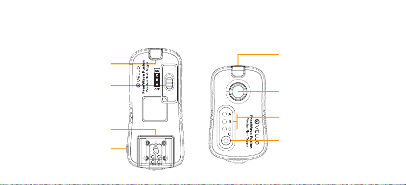
FEATURES DIAGRAM
Confirmation LED
Power (Gro up) Switch
Receiver
Hot Shoe Mount
2.5 mm Outp ut Jack
Confirmation LED
Transmitter
Shut ter Release But ton
Group Indicator
Power Swi tch / Set ting But ton
Page 7
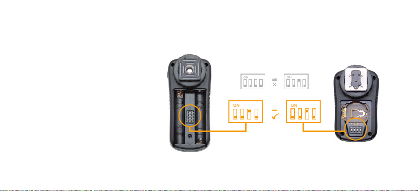
BEFORE YOU BEGIN
Set the D IP swit ch locat ed in the battery
compartment of the Tr ansmitter and
Re ce iv er.
The DI P switch es set a di erent ra dio
frequency for e ach Transmi tter/Receiver
set, s o that mult iple set s of the FreeWave
Fusion and/or additional Fusion Receivers
can be us ed simultaneou sly. You can use
a pen to se t the DIP switche s to your
desired code. A ny combination will work
so long a s the swit ches are se t identi cally
in both t he Transmit ter and Re ceiver(s) of
a single F reeWave Fusio n set.
Inser t 2 AA A batte ries int o the Recei ver.
7
Page 8

8
POWERING UP
Tur n ON the Receiver:
Slide t he Group Sw itch to ei ther A , B, or
C and the unit will power up. The L ED will
flash re d at 2 second i nterv als to ind icate
that th e Receive r is working.
To power down after use , slide th e Group
Switc h back to the O posit ion.
Tur n ON the Tra nsmitter:
Press a nd hold the p ower but ton for 2
second s to power up t he Transmi tter.
The Gro up Indicator ligh t will turn o n and
show the c urrent ly selec ted group. The
Group i ndicato r light will turn o af ter 2
second s and the Tran smitte r will ent er
Standby mode.
To power down after use , press a nd hold
the powe r button for 2 second s. The LE D
at the top of the unit w ill flash 4 t imes at
½ second i nterv als befo re shutt ing itse lf
to indic ate that i t is poweri ng o.
Page 9
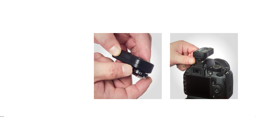
MOUNTING THE TRANSMITTER
1. With your camera an d Receive r OFF,
loosen the Transmitter’s hot shoe
locking ring.
2. Inser t the Transm itter ’s hot shoe on
the camera’s hot shoe mount.
3. Tighten the hot shoe locking ring.
9
Page 10

10
MOUNTING THE RECEIVER
Mount t he receiver on your tr ipod
or stand via one of t he two prov ided
mounting options:
1. Threaded s ocket for a s tandard ¼”
screw mount
2. Accessory shoe (cold shoe) foot
Page 11

CONNECTING THE LIGHTS
11
Conne cting to a Fl ash Uni t:
1. Switch t he flash’s loc king swi tch to the
unlock position
2. Insert the fl ash’s hot sho e foot into t he
Receiver’s hot shoe mount
3. Switch th e flash’s lock ing switch to the
locked position
Connecting to a Studio Light
You will need to use the in cluded St udio
Trigger C able in order to conn ect the
Receiver to a studi o light.
1. Plug the 2 .5mm sid e of the cab le into
the Rece iver’s out put jack .
2. Plug the 3.5m m side of the cable int o
the stu dio light r emote jac k
3. If your studi o light ha s a 1/4” Phono
jack , you will ne ed to use the i ncluded
2.5 mm to 1/4” Phon o cable.
Page 12

12
SETTING THE GROUPS
Slide t he Receive r’s Group/ Power swi tch
to eith er A, B , or C. To assig n multiple
Receivers to the s ame flas h group, si mply
selec t the same g roup let ter for ea ch
Receiver in the fla sh group.
The LED a t the top of the Receive r will
flash re d to confir m that the p ower is on.
Tip: You can combine studio lights
and speedlight s with in the sam e flash gro up.
(Be aware of the independe nt recycling time
of each flash to ens ure all fla sh units are
ready t o fire).
Page 13

SELECTING THE GROUPS
13
1. Gently press the Group/Power button
on the Transmitte r. The group ind icator
LED(s) wil l light up to i ndicate w hich
groups are currently selected.
2. To change gro up selec tions, p ress
theGro up/Powerb uttona gain.Keep
pressing the Gro up/Powe r button t o
cycle t hrough al l the Group options : A
only; B o nly; C onl y; A and B; A an d C;
B and C; A , B and C.
3. To see which groups a re currently
selec ted at any ti me, gent ly press t he
Group /Power button. Th e Group
indicator ligh t will turn o after 2
second s. Howeve r, even after p owering
down, t he tran smitte r will remember
the las t group se lected .
4. To verify light and g roup sele ction,
press t he shutt er relea se butt on on
eithe r the came ra or the F reeWave
Transmitter hal fway. The L ED at the
top of th e Receiver will turn g reen on
each currently selected Receiver.
Page 14

14
USING THE FLASH TRIGGER
1. Co nfirm th at the power on your
Camer a, Transmitter a nd Receive r is
turned on.
2. Press the shutt er button on the ca mera
half way to wake y our flash (i f your flas h
has a wa ke-up fu nction).
3. If yo ur flash does not have a w ake-
up func tion, you m ay be able to turn
o slee p mode. Refer to your fl ash’s
manual for instructions.
4. Fully press the s hutte r button o n
your camera. A ll light s connec ted to
Receivers in the c urrently selec ted
group w ill fire.
Note:
We recommend using a f ully manually
controlled flash with ] ]this dev ice. Sin ce
the FreeWave Fusion do es not tra nsmit
TTL se ttings , you will ne ed to set th e
power output manual ly.
Page 15

USING THE FREEWAVE FUSION AS A REMOTE SHUTTER RELEASE
15
Connecting the Camera:
In orde r to use the re mote shu tter rel ease
funct ion, you wi ll need to u se the incl uded
Fusion shutter release cable.
1. Plug the 2.5m m side of the c able int o
th e Recei ver.
2. Plug the ot her side of t he cable i nto
your camera’s shut ter rele ase terminal.
3. Mount th e Receive r on your camera’s
hot shoe, facin g forwa rds or back wards.
If your c amera’s hot shoe is in us e, you
can use a n accesso ry shoe to attach t he
Receiver to your ca mera , tripod , or
other s uitabl e surfa ce.
Note: I f you are mou nting a fla sh on
your camera, mount the flash directly
onto you r camer a’s hot shoe. T he Fusion
Receiver can be mo unted on a straigh t
bracket. DO NOT M OUNT TH E FLA SH
ON TOP OF T HE FUS ION RECEIVER
since th e Receive r does not send TTL
signa ls to the fla sh.
Page 16

16
REMOTE SHUTTER RELEASE | SINGLE SHOTS
1. Turn on the Rec eiver by sliding the
Group /Power switch to any p osition
other than O.
2. Set your ca mera to the single s hot
setting.
3. Press an d hold the Tran smitter’s
shutter release butt on halfway to
wake or fo cus your ca mera (if set to
Auto Fo cus). The LE D will turn green.
4. Fully depress the s hutte r button o n the
Transmitter. The LED w ill turn red and
the shu tter wil l be trig gered.
Page 17

REMOTE SHUTTER RELEASE | CONTINUOUS MODE
17
1. Turn on the Rec eiver by sliding the
Group /Power switch to any p osition
other than O.
2. Set your ca mera to the continuous
Shooting mode.
3. Press an d hold the Tran smitter’s
shutter release butt on half way to wake
or focus y our came ra (if set to Auto
Focus). The LED will turn green.
4. A full pres s of the Transm itter ’s shutte r
button will tri gger th e camer a to take
contin uous pho tos until yo u releas e the
shutter button.
Page 18

18
REMOTE SHUTTER RELEASE | SELF-TIMER MODE
1. Turn on the Rec eiver by sliding the
Group /Power switch to any p osition
other than O.
2. Set your ca mera to the delay/se lf-time r
setting.
3. Press an d hold the Tran smitter’s
shutter release butt on half way to
wake or fo cus your ca mera (if set to
Auto Fo cus). The LE D will turn green.
4. Fully depress the s hutte r button o n
the Transmitter. The L ED will turn red
and the shutter w ill be tri ggered after a
pre-set delay a s set by your c amera .
Page 19

REMOTE SHUTTER RELEASE | BULB MODE (LONG EXPOSURE)
19
1. Turn on the Rec eiver by sliding the
Group /Power switch to any p osition
other than O.
2. Set your ca mera to the bulb set ting.
3. Press an d hold the Tran smitter’s
shutter release butt on half way to
wake or fo cus your ca mera (if s et to
Auto Fo cus). The LE D will turn green.
4. Press and hold the Tran smitte r’s
shutter butt on. The sh utter w ill remai n
open un til you rele ase the shutter
button.
Page 20

20
CAMERA RELEASE CABLES
The FreeWave Fusion’s Shu tter Release
Cable e nables t he remot e to function as
a remote shutte r releas e with cer tain
model s of camer as. By ch anging t he
shutter release cable, a single F reeWave
Fusion Receiver c an work wi th many ot her
camer as as wel l.
Vello shutter rel ease cab les are li sted to
the rig ht. For t hese cab les, and c ables for
other c amera m odels, c heck with your
Vello dealer.
RCC-C2 – Canon EOS 10D / 20D / 30D / 40D / 50D / 5D / 5D Mark II / 5D Mark III 7D / 1DS /
Mark II / Mark II N / Mark III / Mark IV / 1Ds / Mark II / Mark III / 1DX
RCC-N1 – Nikon D1/ D1H / D1X / D2 / D2H / D2HS / D2X / D2 XS / D3 / D3X / D3S / D4 / D200 / D30 0 / D300S
/ D700/ D8 00/ D800e Fuji S3pro / S5Pro Kodak DCS-14N
RCC-C1 – Canon E OS 30/ 33/ 50/ 60 D/ 300/
Digi tal Rebel: (30 0D) /XT (350 D)/ XTi (400D)/ X Si (450D)/ XS (1000 D)/T1i (500D)/ T2 i (550D)/ T3 (1100D)/
T3i (600 D), Powershot: G10, G11, G12, G1 X / Contax N / 645 Pentax K100D / K110D / K200D / K10D /
K20D / K-5 / K-7 / *ist DS / DS2 / DL2 / DL / D Sigma SD1
Samsung GX-1S / GX-1L / GX-10 / GX-20 / NX Series
RCC-S1 – Sony A100 / A200 / A290 / A300 / A 320 / A350 / A380 / A390 /
A500 / A500 / A560 / A 580 / A700 / A850 / A900 /
SLT A33 / SLT A55 / SLT A77 / SLT A35 / SLT A65
RCC-O1 – Olympus E520 / E510 / E420 / E410 / E400 /
E450 / E620 / E-P2 / E-PL2 / SP-570UZ /
SP-560UZ / SP-550UZ / SP-510UZ / XZ-1
Pen: E- PL2 / E-P2 / E- PM1 / E-PL3 / E- P3 /
OM-D: EM-5
RCC-O2 – Olympus E-1/ E-3/ E-5
RCC-N3 – Nikon D70s / D80
RCC-N2 – Nikon D90 / D3100 / D3200 / D5000 /
D7000 / D5100
RCC-P1 – Pan asonic DM C-L1 / DM C-L10 /
DMC- G1 / DMC-GF1 / DMC- GH1 /
DMC- GX1/ DMC-G2 / DMC- GH2 /
DMC- G3 / DMC-G10 / DMC- FZ100 /
DMC -FZ1 50
RCC-O2
RCC -P1
RCC-N2
RCC-N3
RCC -O1
RCC- S1
RCC-C2
RCC -N1
RCC -C1
Page 21

SPECIFICATIONS
21
Transmitter Receiver
Power
Battery Life* 3 Ye ar s 300 Hours
DIP Switch Settings
Range
Frequency 2.4 GH z
Confirmation LEDs 2 Color
1 CR-2032
16 possibl e codes
100m (32 0 ft.) wit h no obstr uction s
* In stan d by mode.
2 AAA
Transmitter Receiver
Flash Trigger
Groups
Lights per Group Unlimited
Shut ter Mode s
(settings controlled
by ca mera)
7 possib le groups :
A; B; C; A B; AC; BC; AB C
Single Shot, Continuous,
Self-Timer, & Bulb
Page 22

22
TROUBLESHOOTING
Problems with t he FreeWave Fusion can
usual ly be trac ed to the fol lowing mo st
common causes. Perfor m the following
steps t o diagno se and corr ect the
problem:
Check t he conta ct betwe en the lig ht’s hot
shoe foo t and the Rec eiver’s ho t shoe.
Make sur e the light’s lockin g switch i s set
to the lock position.
Check t hat the shutter re lease cable and/
or stud io light ca ble are in go od condition
and properly connected.
Make sure that the Re ceiver i s powered
on and at the correc t setting.
Remove th e batte ries from t he
Transmitter and Re ceiver, and change the
chann el by rear rangin g the DIP switche s
to a die rent combinatio n, taki ng care
to ensu re that bot h the Transm itter and
Receiver are set id entica lly.
If you en counter a ny inter ferenc e on the
initi al setti ng, try c hangin g the chan nel
by choos ing a die rent DIP s witch
combination.
When using the FreeWave Fusion a s a
shutter release, your c amera m ay not be
able to re lease t he shutt er if the le ns is
set to Au to Focus and focus ca nnot be
achieve d on subje ct. Swi tch your ca mera
to manu al focus to ensure proper shutter
release.
Page 23

FCC COMPLIANCE
23
This eq uipmen t genera tes, use s, and
can rad iate rad io frequency ene rgy, and
if not in stalle d and used in a ccordan ce
with th e instructions , may caus e harmfu l
interference to radio communications.
This eq uipmen t has been tested and
found to c omply wi th the limi ts for a
Class B d igital device pur suant to Part
15 of the FCC Rules. The se limits a re
desig nated to pr ovide rea sonabl e
protection against harmful interference
in a residential installation.
There i s no guarantee th at inter ference
will not occur in a particular installation.
If this e quipme nt does cause harm ful
inter ference to radio o r television
reception, which can be determi ned by
turning the equi pment ON or OFF, the
user is e ncoura ged to tr y to correct
the int erference by one or m ore of the
following measures:
1. Reorie nt or relo cate the re ceivin g
antenna;
2. Increas e the dist ance bet ween the
equip ment and t he receiver.
This dev ice complies with P art
Subpa rt B, C lass B of th e FCC Rules .
15,
Oper ation is su bject to t he follow ing
two conditions:
1. This dev ice may not c ause
harmful interference.
2. This devic e must acce pt any
interference received, including
inter ference that may c ause
undesired operation.
Any cha nges or mod ificati ons (incl uding
the ant enna) mad e to this dev ice that
are not expressly approve d by the
manuf acture r may void the u ser’s
authority to operate the equipment.
Page 24

Limited One-Year Warranty
Vello provides a limited warranty that this product is free from defects in materials and workmanship to the
original purchaser under normal use for a period of one (1) year from the original purchase date,
or thirty (30) days after replacement whichever occurs later Vello's responsibility with respect to
this limited warranty shall be limited solely to repair or replacement, at its option, of any product
which fails during normal consumer use. This warranty does not extend to damage or failure
which results from misuse, neglect, accident, alteration, abuse, improper installation or maintenance. EXCEPT
AS PROVIDED HEREIN, VELLO MAKES NEITHER ANY EXPRESS WARRANTIES NOR ANY IMPLIED
WARRANTIES. INCLUDING BUT NOT LIMITED TO ANY IMPLIED WARRANTY OF MERCHANTABILITY
OR FITNESS FOR A PARTICULAR PURPOSE. To obtain a replacement during the time of this warranty please
return the defective Item with proof of purchase along with an RMA number to the place of purchase. This
warranty gives you specic legal rights, and you may also have other rights which vary from state to state.
Gradus Group
 Loading...