

Page 1
D
R
W
A
K
L
U
E
O
C
O
S
W
-
T
-
2
N
G
W
W
R
0
D
W
V
COLOU
KLEURE
EFFET
EFECTO
FARBEN
P
WASH
N WASH
ASH C
WASH
-WASHE
L
FFECT
-EFFEC
ULEUR
OLOR -
FFEKT -
24 x 1
- 24 x 1
24 LED
4 LEDs
24 x 1W
4
RGB LE
RGB-L
GB DE
RGB DE
RGB-LE
1
Ds
EDS
1
1W
s
USER M
GEBRUI
NOTICE
MANUA
BEDIEN
NUAL
ERSHA
D’EMPL
DEL U
NGSAN
NDLEIDI
I
UARIO
LEITUN
G
Page 2
o
v
o
P
i
t
v
s
n
e
yc
c
v
m
4
k
s
e
A
t
c
m
y
t
e
a
e
G
r
e
k
c
0
e
o
p
u
0
r
m
o
P
n
a
r
e
b
h
e
p
c
r
h
r
e
r
e
d
e
e
u
d
a
s
L
o
t
o
y
d
e
t
c
h
t
e
a
a
e
a
t
o
n
c
g
o
r
e
s
x
t
d
g
away
a
W
p
y
d
n
t
e
a
s
e
e
h
h
h
c
s
v
n
t
o
2
o
g
t
x
c
a
t
F
a
d
s
r
yo
n
n
e
p
t
H
a
e
e
tag
o
H
g
m
m
(e.g
V
C
r
n
2
f
e
d
s
e
E
o
n
e
d
n
H
r
o
e
t
a
e
2
W
a
t
e
e
p
c
o
e
h
a
V
o
i
e
t
r
E
y
o
n
t
s
f
y
p
h
e
a
s
W
r
n
h
r
t
c
a
c
e
y
1.
Introduct
T
all residen
Im
portant en
If i
n doubt, co
Th
ank you for
de
ice was da
Th
e VDPLW2
m
unting brac
2.
Safety In
VD
This
the e
a sp
rec
Be v
Do n
LW24
on
s of the Eu
ironmental
mbol on th
vironment.
cialized co
ling service.
ntact your l
hoosing HQ
aged in tra
01 is a 4-ch
et, 1 x powe
tructions
ry careful d
t touch the
1 – CO
opean Uni
information
e device or
Do not disp
pany for rec
Respect the
cal waste
OWER! Pl
sit, don't ins
nnel, DMX cable and t
ring the ins
evice durin
OUR
n
about this
he package
se of the uni
cling. This
local enviro
isposal au
ase read th
all or use it
ontrolled wa
is manual.
allation: tou
operation
ASH E
roduct
indicates th
t (or batterie
evice shoul
mental rule
horities.
manual tho
nd contact
h effect usi
hing live wi
s the housi
FECT -
t disposal o
s) as unsort
be returne
.
oughly befor
ur dealer.
24 x 1W L
es can caus
heats up.
4 x 1
the device
d municipal
to your dis
bringing thi
Ds. Conten
life-threate
RGB L
fter its lifec
waste; it sh
ributor or to
s device into
ts: 1 x VDPL
ning electro
Ds
cle could ha
uld be take
a local
service. If t
W2401, 1 x
hocks.
m
to
e
•
Damage ca
will not acc
•
qualified
•
Do not swit
against da
•
This device
person carr
Make sure
•
•
Do not crim
•
Disconnect
•
Do not look
•
Keep the d
•
Note that d
•
Keep the d
3.
General
•
This device
used indoo
•
Lighting eff
Do not sha
•
•
Select a lo
distance of
•
Use an app
Kee
this device
Unpl
used by disr
pt responsi
echnician s
h the devic
age by leav
falls under
hat the avail
p the power
the device f
directly at t
vice away f
vice away f
is designed
s with an alt
cts are not
e the devic
ation where
ropriate saf
the main
out the ele
mage caus
uidelines
.5m betwee
from r
lead before
ard of cer
ility for any
ould install
on immedi
ing it switch
rotection cl
tric connec
able voltage
cord and pr
om the mai
e light sour
om splashin
d by user m
om children
for professi
rnating cur
esigned for
. Avoid brut
the device i
n the device’
ty cable to fi
in and mois
opening the
ain guidelin
nsuing def
nd service t
tely after it
d off until it
ss I. It is the
ion.
does not ex
tect it again
s to clean it
e as sensiti
and drippi
odifications
and unauth
nal use on s
ent of max.
permanent
force when
protected a
s light outpu
the device
ure.
housing.
s in this ma
cts or probl
is device.
as been ex
as reached
refore essen
eed the vol
t damage.
or when it is
e people m
liquids. N
o the devic
rised users.
30VAC/50
peration: re
installing or
ainst extre
and any illu
e, in disc
.
DLS
ual is not c
ms.
osed to cha
room temp
tial that the
age stated i
ave an auth
not in use.
go into epi
ver put obje
is not cove
s, theatres,
z.
ular operati
operating th
e heat, dus
inated surf
8).
vered by th
es in tem
rature.
evice be ea
the specifi
orised deale
andle the p
leptic seizur
cts filled wit
ed by the w
etc. The
n breaks w
device.
and moistu
ce.
warranty a
erature. Pro
rthed. Have
ations of thi
r replace it i
wer cord b
if they do.
liquid on to
rranty.
D
PLW2401 s
ll prolong th
e. Respect
d the deale
ect the devi
qualified
manual.
necessary.
the plug onl
of the devi
ould only b
ir lives.
minimum
e
.
e.
VD
PLW2401
2
HQPO
ER
Page 3

• Familiarise yourself with the functions of the device before actually using it. Do not allow operation by unqualified
people. Any damage that may occur will most probably be due to unprofessional use of the device.
• Use the original packaging if the device is to be transported.
• All modifications of the device are forbidden for safety reasons.
• Only use the device for its intended purpose. All other uses may lead to short circuits, burns, electroshocks,
crash, etc. Using the device in an unauthorised way will void the warranty.
4. Installation
a) Mounting the Device
• Have the device installed by a qualified person, respecting EN 60598-2-17 and all other applicable norms.
• The carrying construction must be able to support 10 times the weight of the device for 1 hour without deforming.
• The installation must always be secured with a secondary attachment e.g. a safety cable.
• Never stand directly below the device when it is being mounted, removed or serviced. Have a qualified technician
check the device once a year and once before you bring it into service.
• Install the device in a location with few passers-by that is inaccessible to unauthorised persons.
• Overhead mounting requires extensive experience: calculating workload limits, determining the installation
material to be used… Have the material and the device itself checked regularly. Do not attempt to install the
device yourself if you lack these qualifications as improper installation may result in injuries.
• Adjust the desired inclination angle via the mounting bracket and tighten the bracket screws.
• Make sure there is no flammable material within a 0.5m radius of the device.
• Have a qualified electrician carry out the electric connection.
• Connect the device to the mains with the power plug. Do not connect it to a dimming pack.
• The installation has to be approved by an expert before the device is taken into service.
b) Fuse
• Only fit or replace a fuse when the device is unplugged from the mains.
• Replace a blown fuse with a fuse of the same type and rating (see “Technical Specifications”):
1. Remove the fuse holder under the power socket at the back of the device.
2. Remove the old fuse and install a new one.
3. Replace the fuse holder.
5. Use
Auto Mode
Set the DIP switches according to the table below:
ON OFF Function
1,2,3 4,5,6,7,8,9,10 Red
4,5,6 1,2,3,7,8,9,10 Green
7,8 1,2,3,4,5,6,9,10 Blue
7,9 1,2,3,4,5,6,8,10 Fast colour change
7,8,9 2,3,4,5,6,7,10 Slow colour change
1,9 2,3,4,5,6,7,8,10
Strobe mode, colour and speed change according
to the setting of the other DIP switches
VDPLW2401 HQPOWER
3
Page 4
Master/Slave Mode
Master Mode Slave Mode
ON Function ON Function
1,2,3 Red
4,5,6 Green
7,8 Blue
7,9 Automatic 7-colour fast changing
1,10 Slave function
8,9 Automatic 7-colour slow changing
1,9 Frequently flashing from red to green to blue
DMX Mode
Set the desired DMX address using DIP switches 1 to 9:
SW1 SW2 SW3 SW4 SW5 SW6 SW7 SW8 SW9 SW10
1 2 4 8 16 32 64 128 256 ON
6. DMX
DMX512 Connection
Connect the provided XLR cable to the female 3-pin XLR output of your controller and the other side to the male 3pin XLR input of the VDPLW2401. Multiple VDPLW2401s can be linked through serial linking. The linking cable
should be a two-core screened cable with XLR input and output connectors.
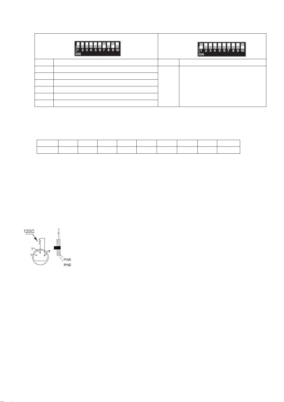
DMX512 Chain with Termination
A DMX terminator is recommended for installations where the DMX cable has to run a
long distance or is in an electrically noisy environment (e.g. discos). The terminator
prevents corruption of the digital control signal by electrical noise. The DMX terminator is
simply an XLR plug with a 120Ω resistor between pins 2 and 3, which is then plugged into
the XLR output socket of the last device in the chain.
Please see illustrations.
DMX Start Address
All DMX-controlled devices need a digital start address so that the correct device responds to the signals. This start
address is the channel number from which the device starts to “listen” to the DMX controller. Enter the correct
number and read it from the display located on the base of the VDPLW2401.
You can use the same starting address for a whole group of devices or enter an individual one for every device.
When all devices have the same address, all the VDPLW2401s will “listen” to the control signal on one particular
channel. In other words: changing the settings of one channel will affect all devices simultaneously. If you set
different addresses, each device will “listen” to a separate channel number. Changing the settings of one channel will
only affect the device in question.
VDPLW2401 HQPOWER
4
Page 5
Detailed DMX Values per Channel
Channel Function From To Description
1 Dimmer/Shutter
2 Red 0 255 From 0 to 100% output
3 Green 0 255 From 0 to 100% output
4 Blue 0 255 From 0 to 100% output
0 152 Dimmer from 0 to 100%
153 255 Strobe function from slow to fast
7. Cleaning and Maintenance
1. All screws should be tightened and free of corrosion.
2. The housing, visible parts, mounting supports and the installation location (e.g. ceiling, suspension, trussing)
should not be deformed, modified or tampered with e.g. do not drill extra holes in mounting supports, do not
change the location of the connections.
3. Moving mechanic parts must not show any signs of wear and tear.
4. The electric power supply cables must not show any damage. Have a qualified technician maintain the device.
5. Disconnect the device from the mains prior to maintenance activities.
6. Wipe the device regularly with a moist, lint-free cloth. Do not use alcohol or solvents.
7. There are no user-serviceable parts.
8. Contact your dealer for spare parts if necessary.
8. Technical Specifications
LEDs 24 x 1W RGB
Flash Rate 18Hz
DMX512 4 channels
DMX Connection 3-pin XLR
Power Supply max. 230VAC/50Hz
Power Consumption max. 36W
Fuse F2A, 250VAC (5 x 20mm) (order code FF2N)
Dimensions 210 x 135 x 125mm
Total Weight 2.5kg
Max. Ambient Temperature 45°C
Max. Housing Temperature 60°C
Use this device with original accessories only. Velleman nv cannot be held responsible in the event of
damage or injury resulted from (incorrect) use of this device. For more info concerning this product, please
visit our website www.hqpower.com. The information in this manual is subject to change without prior
notice.
VDPLW2401 HQPOWER
5
Page 6
aBeHe
a
P
z
ywegg
b
yc
t
n
w
jd
d
o
s
d
r
v
m
b
gs
k
ge
c
o
e
e
s
e
o
e
e
o
s
r
k
c
e
1
a
y
e
n
e
u
r
L
s
i
o
e
diging
n
s
r
n
n
s
o
d
n
u
e
n
o
g
g
e
n
s
U
s
a
e
e
d
a
e
n
a
e
o
u
k
u
e
o
(t
o
t
d
r
d
s
s
o
m
m
s
e
h
a
g
W
d
n
b
d
t
o
n
ge
e
b
e
w
g
a
o
n
a
u
v
w
a
u
s
e
e
g
t
g
F
d
z
a
o
n
e
a
n
a
o
d
a
oang
a
m
gh
r
.
e
p
d
n
G
l
e
jd
n
l
a
jn
h
jk
g
a
p
e
e
e
t
n
5
e
e
s
w
W
s
e
j
t
e
h
b
w
e
a
e
g
o
jn
e
t
t
d
n
e
n
L
u
m
t
e
e
o
s
g
a
e
n
v
ga
t
e
ge
o
a
n
W
e
g.
n
u
0
1.
Inleiding
A
n alle inge
langrijke m
bt u vrage
D
nk u voor u
be
schadigd ti
2.
Veilighei
VD
Wee
te ve
Raa
LW240
etenen van
ilieu-inform
Dit s
mbool op h
eworpen, di
niet
ij het gewo
rec
lage. U mo
plaa
selijke milie
, contactee
aankoop!
ens het tran
sinstruct
voorzichtig
mijden.
het toestel
de Europe
t toestel sch
dan de pla
ees deze h
es
bij de install
– KLE
tie betreff
t toestel of
e huishoud
t dit toestel
wetgeving.
port, install
iet aan wan
REN
e Unie
nde dit pro
e verpakki
de kan toe
lijke afval; h
aar uw ver
atselijke au
ndleiding gr
er het dan
tie: raak ge
neer het in
ASH-E
uct
geeft aan
rengen aan
et moet bij e
eler of naar
oriteiten in
ndig voor u
iet en raadp
n kabels aa
ebruik is: d
FECT -
at, als het
het milieu.
en gespecia
een lokaal r
ake verwi
het toestel i
leeg uw dea
n die onder
behuizing
24 x 1
a zijn leven
ooi dit toest
iseerd bedri
cyclagepun
ering.
gebruik ne
er.
troom staa
ordt warm.
RGB-
cyclus word
l (en event
terechtko
brengen. R
mt. Werd h
om dodelijk
EDS
t
ele batterije
en voor
especteer d
t toestel
e elektrosho
n)
cks
•
De garantie
de verantw
•
Laat dit toe
•
Om bescha
temperatuu
•
Dit toestel
technicus
•
De beschik
De voedin
•
Trek de ste
•
Wanneer u
•
bepaalde
•
Kijk niet re
•
Schade do
•
Houd dit to
3.
Algemen
•
Dit toestel i
gebruiken
•
Lichteffecte
•
Schud het t
Installeer h
•
m tussen d
•
Maak het t
Bes
herm dit toe
Verz
geldt niet v
alt onder be
het toestel v
htstreeks in
n aansluiten
n zijn niet o
estel vast m
ker u ervan
ordelijkheid
tel installer
te ver
schommeli
oet de elekt
are netspa
kabel mag
ker uit het
ur. Dit is no
r wijziginge
stel uit de b
richtlijn
ontworpen
estel niet d
t toestel we
lichtuitgan
tel tegen re
dat het toes
or schade d
afwijzen vo
n en onderh
mijden, zet
en. Wacht
chermings
ische aansl
ning mag ni
iet omgepl
topcontact
or het eers
rmaal en de
e lichtbron.
die de geb
urt van kin
n
voor profes
op een wis
tworpen vo
oreen. Ver
van extre
van het toe
t een gesc
en en voch
tel niet aan
oor het ne
r defecten o
ouden door
het toestel
tot het toest
lasse I, wat
iting verzor
t hoger zijn
oid of besch
rek niet aan
gebruikt, k
eventuele r
De lichtbro
uiker heeft
eren en onb
ioneel gebr
elspanning
r continue
ijd brute kr
e temperat
tel en het b
ikte veilighe
igheid.
esloten is o
ren van bep
f problemen
en gescho
est niet aa
l op kamert
il zeggen d
en.
dan de spa
adigd zijn. L
de kabel!) v
n dit gepaar
ok of geur z
kan bij gev
ebracht
evoegden.
ik op podia,
an maximu
erking: regel
cht tijdens d
ren, vochti
lichte oppe
idskabel (bv
een stroom
alde richtli
die hier rec
lde technicu
onmiddelli
mperatuur
t het toeste
ning in de s
at uw deal
ordat u het
gaan met
l geleidelijk
elige mens
an het toes
in disco's, e
230 VAC/
matige ond
e installatie
eid en stof.
vlak.
VDLSC8).
bron alvoren
en in deze
tstreeks ver
s.
nadat het
ekomen is.
l geaard mo
ecificaties
r zo nodig e
toestel reini
en lichte ro
aan verdwi
n leiden tot
el vallen nie
z. U mag di
0 Hz.
rbrekingen
n de bedie
Zorg voor e
s het te ope
andleiding
and mee h
erd blootge
t zijn. Een
chteraan de
n nieuwe k
t en als u h
kontwikkeli
en.
en aanval
t onder de
toestel enk
oen ze lan
ing van dit t
n minimum
en.
n uw dealer
uden.
teld aan
eschoolde
handleidin
bel plaatse
t niet gebrui
en een
an epilepsie
rantie.
l binnensh
r meegaan.
estel.
fstand van
zal
.
kt.
.
is
,5
VD
PLW2401
6
HQPO
ER
Page 7

• Leer eerst de functies van het toestel kennen voor u het gaat gebruiken. Ongeschoolde personen mogen dit
toestel niet gebruiken. Meestal is beschadiging het gevolg van onprofessioneel gebruik.
• Gebruik de oorspronkelijke verpakking wanneer u het toestel vervoert.
• Om veiligheidsredenen mag de gebruiker geen wijzigingen aanbrengen aan het toestel.
• Gebruik het toestel enkel waarvoor het gemaakt is. Andere toepassingen kunnen leiden tot kortsluitingen,
brandwonden, elektrische schokken, enz. Bij onoordeelkundig gebruik vervalt de garantie.
4. Installatie
a) Het toestel monteren
• Laat een geschoolde technicus dit toestel installeren conform EN 60598-2-17 en andere toepasselijke normen.
• De constructie waaraan het toestel wordt bevestigd, moet gedurende 1 uur 10 x het gewicht van dit toestel
kunnen dragen zonder te vervormen.
• Maak het toestel ook vast met een veiligheidskabel.
• Sta nooit recht onder het toestel wanneer u het monteert, verwijdert of schoonveegt. Laat het toestel controleren
door een geschoolde technicus voor u het in gebruik neemt en laat het 1 x per jaar volledig nakijken.
• Installeer dit toestel op een plaats waar niemand langs moet lopen, kan neerzitten of het toestel kan aanraken.
• Een degelijke praktijkervaring is vereist voor de plaatsing van dit toestel. U moet de maximumbelasting van de
draagconstructie kunnen berekenen, weten welk constructiemateriaal u kunt gebruiken en u moet het gebruikte
materiaal en het toestel af en toe laten nakijken. Monteer het toestel niet zelf indien u er geen ervaring mee heeft.
Een slechte montage kan leiden tot verwondingen.
• Regel de gewenste invalshoek door middel van de montagebeugel en draai de regelschroeven stevig aan.
• Verwijder alle brandbaar materiaal in een straal van 0,5 m rond het toestel.
• Een geschoolde elektricien moet het toestel aansluiten.
• Sluit het toestel via de stekker aan op het lichtnet. Sluit het niet aan op een dimmerpack.
• De installatie moet voor het eerste gebruik gekeurd worden door een expert.
b) Zekering
• U mag een zekering enkel plaatsen of vervangen wanneer het toestel niet is aangesloten op het lichtnet.
• Vervang een gesprongen zekering door een zekering van hetzelfde type en met dezelfde specificaties (zie
‘Technische specificaties’). Ga als volgt te werk:
1. Verwijder de zekeringhouder onder de voedingsaansluiting achteraan het toestel.
2. Verwijder de oude zekering en breng de nieuwe in.
3. Plaats de zekeringhouder weer in de behuizing.
5. Gebruik
Automatische aansturing
Stel de DIP-schakelaars in volgens de tabel hieronder:
ON OFF Functie
1,2,3 4,5,6,7,8,9,10 Rood
4,5,6 1,2,3,7,8,9,10 Groen
7,8 1,2,3,4,5,6,9,10 Blauw
7,9 1,2,3,4,5,6,8,10 Snelle kleurverandering
7,8,9 2,3,4,5,6,7,10 Trage kleurverandering
1,9 2,3,4,5,6,7,8,10
Stroboscoop, kleur- en snelheidsverandering
volgens instelling van de andere DIP-schakelaars
VDPLW2401 HQPOWER
7
Page 8

M
a
M
e
M
uma
g
M
M
A
tGeU kWa
a
awa
r
n
g
1
l
ge
i
nang
u
n
e
u
r
c
k
n
s
t
n
M
R
n
p
e
e
o
i
X
l
i
s
a
v
s
d
v
k
k
g
t
S
d
D
u
e
d
g
w
t
e
m
e
v
l
e
a
r
t
e
W
6
e
U
e
c
s
s
s
e
o
z
e
-
h
g
n
s
a
e
p
o
t
a
s
e
e
VDP
r
X
s
t
n
gdig
e
a
VDPL
e
h
e
n
S
2
r
a
m
a
e
D
t
a
n
n
e
1
N
r
o
ga
r
t
d
a
s
o
M
a
d
g
w
W
d
n
m
s
k
e
r
n
ster-slaves
Maste
turing
Slave
X-aansturi
D
S
lecteer het
6.
DMX
D
X512-aans
Sl
it de mee
nnelijke 3-p
be
hulp van ee
uit
saansl
D
X512-kete
D
X-startadr
ll
e DMX-gest
Di
digitale sta
ef het corre
unt één en
nneer u éé
w
nneer u de i
W
nneer u ver
nneer u de i
ON
1,2,3
4,5,6
7,8
7,9
8,9
1,9
ewenste D
SW
1
uiting
leverde XL
n XLR-inga
seriële kop
itingen.
met eindw
s
tadres is het
te nummer
el startadre
enkel start
nstellingen
nstellingen
Functie
Roo
Groen
Blauw
Snelle, au
Trage, au
Flisten va
tomatische
omatische
rood naar
X-adres me
SW2
2
-kabel aan
eling. Gebr
erstand
E
en DMX ein
n omgevin
e
c
rruptie van
n
ets meer da
LR-stekker
Z
ie de illustra
urde toeste
len hebben
kanaalnum
n en lees h
gebruiken
dres instelt,
oor 1 kanaa
chillende a
ressen inst
an een kan
SW3
4
van de V
leurverande
leurverande
roen naar b
DIP-schak
W4 S
8 1
e vrouwelijk
PLW2401.
ik daarvoor
weerstand i
met veel el
het digitale
n een XLR-
ordt dan aa
ie links.
en digitaal
er van waa
t af op de di
oor een gro
zullen alle t
verandert,
lt, dan luist
al verandert
ring (7)
ing (7)
lauw
laar 1 tot 9:
5 SW6
32
3-pin XLR
kunt versc
een 2-aderi
s aanbevole
ktrische rui
ontrolesign
tekker met
ngesloten o
uitgang van
eidene
e afgesche
als de DM
(bv. een di
al door elek
en weersta
de XLR-uit
tartadres n
rop het toes
play onder
p toestellen
estellen ‘lui
ullen alle to
rt elk toestel
, zal enkel h
el ‘luistert’ n
an uw
of u kunt p
teren’ naar
stellen er t
naar een a
t toestel op
ON
1,10
SW7
64
, zodat h
Functie
SW8
128
de controlle
LW2401’s
mde kabel
-kabel vrij l
cotheek). D
rische ruis.
d van 120 Ω
ang van he
t juiste toes
ar het sign
W2401.
r toestel ee
etzelfde ka
elijk op rea
der kanaal.
dat kanaal r
Slave
W9 SW
56 O
en de ande
an elkaar k
et XLR in
ng is of wo
eindweers
e DMX ein
van pin 2 n
laatste toe
tel reageert
al van de D
nieuw start
aal. Met an
eren.
Met andere
ageren.
0
e kant van
ppelen met
ng- en
dt gebruikt i
and voorko
weerstand i
ar 3. Deze
tel in de ree
p de signal
X controlle
dres ingeve
ere woorde
oorden:
e
t
s.
n.
.
n.
:
VD
PLW2401
8
HQPO
ER
Page 9

Gedetailleerde DMX-waarden per kanaal
Kanaal Functie Van Tot Omschrijving
1 Dimmer/Sluiter
2 Rood 0 255 Van 0 tot 100 %
3 Groen 0 255 Van 0 tot 100 %
4 Blauw 0 255 Van 0 tot 100 %
0 152 Dimmer van 0 tot 100 %
153 255 Stroboscoop van traag naar snel
7. Reiniging en onderhoud
1. Alle gebruikte schroeven moeten goed zijn aangespannen en mogen geen sporen van roest vertonen.
2. De behuizing, de lenzen, de montagebeugels en de montageplaats (bv. het plafond of het gebinte) mogen niet
vervormd zijn of aangepast worden (geen extra gaten in montagebeugels, aansluitingen niet verplaatsen, enz.)
3. Mechanisch bewegende delen mogen geen sporen van slijtage vertonen en mogen niet onregelmatig bewegen.
4. De voedingskabels mogen niet beschadigd zijn. Laat het toestel onderhouden door een geschoolde technicus.
5. Ontkoppel het toestel van het lichtnet voor u aan onderhoudswerkzaamheden begint.
6. Maak het toestel geregeld schoon met een vochtige, niet pluizende doek. Gebruik geen alcohol of solvent.
7. De gebruiker mag geen onderdelen vervangen.
8. Bestel eventuele reserveonderdelen bij uw dealer.
8. Technische specificaties
Leds 24 RGB-leds van elk 1 W
Flitssnelheid 18 Hz
DMX512 4 kanalen
DMX-aansluiting 3-pin XLR
Voeding max. 230 VAC/50 Hz
Verbruik max. 36 W
Zekering F2A, 250 VAC (5 x 20 mm) (ordercode FF2N)
Afmetingen 210 x 135 x 125 mm
Gewicht 2,5 kg
Max. omgevingstemperatuur 45 °C
Max. temperatuur behuizing 60 °C
Gebruik dit toestel enkel met originele accessoires. Velleman nv is niet aansprakelijk voor schade of
kwetsuren bij (verkeerd) gebruik van dit toestel. Voor meer informatie over dit product, zie
www.hqpower.com. De informatie in deze handleiding kan te allen tijde worden gewijzigd zonder
voorafgaande kennisgeving.
VDPLW2401 HQPOWER
9
Page 10

uDeEn
o
p
P
i
o
h
prégle
e
m
i
d
s
n
s
r
a
m
e
e
a
e
s
m
e
e
u
p
a
é
a
0
e
y
'
a
a
o
t
v
gé
é
t
e
r
n
e
n
n
r
n
e
o
e
p
a
p
d
a
a
e
'
l
r
t
f
t
u
L
o
b
p
r
s
ê
s
a
a
s
a
o
s
à
o
r
e
e
q
l
t
S
c
o
a
n
e
s
s
m
e
o
ê
n
a
o
n
p
s
e
v
e
é
e
l
d
L
n
’
u
c
c
o
t
e
é
e
d
m
é
r
e
e
e
o
C
u
e
e
m
V
u
o
î
2
i
’
d
e
a
o
a
e
r
s
u
n
s
d
d
n
è
2
s
n
e
p
e
î
R
e
c
e
i
u
v
s
e
'
p
p
n
s
h
2
s
n
o
é
u
e
E
e
e
.
e
i
e
m
e
c
e
'
n
C
a
E
n
r
o
W
r
e
d
.
c
e
.
s
1.
Introduct
A
x résidents
s informati
cas de qu
N
us vous re
l’a
pareil a été
2.
Prescript
VD
Ce s
l'env
déc
équi
Être
Ne p
LW24
on
de l'Union
ns environ
mbole sur l
ironnement.
ets municip
ements us
mentation l
stions, con
ercions de
endomma
ons de s
rudent lors
s toucher l’
1 – EFF
uropéenn
nementales
appareil ou
Ne pas jete
ux non suje
és à votre
cale relative
acter les a
otre achat !
pendant le
curité
de l’installati
ppareil lors
ET WA
importante
'emballage i
un appareil
s au tri séle
ournisseur
à la protecti
torités loc
ire la prése
transport, n
on : toucher
u’il est en s
H COU
s concerna
ndique que l
électrique o
tif ; une dé
u à un servi
on de l’envir
les pour éli
te notice at
pas l’install
un câble so
rvice : le b
EUR -
t ce produ
élimination
électroniqu
hèterie trait
e de recycl
nnement.
mination.
entivement
r et consult
s tension p
îtier chauffe
4 LED
t
’un appareil
e (et des pil
ra l’appareil
e local. Il
vant la mis
r votre reve
ut causer d
!
GB D
en fin de vi
s éventuell
en question
onvient de r
en service
ndeur.
s électroch
1W
peut pollue
s) parmi les
Renvoyer l
specter la
e l’appareil
cs mortels.
s
Si
•
La garantie
revendeur
•
Confier l’in
•
Ne pas bra
attendre ju
•
Cet apparei
qualifié doit
•
La tension
Le câble d’
•
câble d’ali
Débrancher
•
La premièr
•
Toute fumé
•
Ne pas rega
•
Les domm
•
Garder votr
3.
Directive
•
Cet apparei
appareil à l’
•
Un effet lu
Éviter de s
•
•
Choisir un
Respecter
•
Fixer l’appa
Prot
Débr
ne s’appliqu
éclinera tou
tallation et l’
cher l’appa
qu’à ce que
l ressort à la
établir la co
éseau ne p
limentation
entation si n
l’appareil s’il
mise en se
rder directem
l a été dével
intérieur et l
ineux n’est
couer l’app
ndroit où l’a
ne distance
reil à l’aide
er l’appare
ncher le câ
ou odeur d
es occasio
VDPLW24
général
il contre la p
ble d'alimen
e pas aux d
e responsa
ntretien à u
eil après ex
l’appareil ait
classe de p
nexion élec
ut pas dépa
e peut pas
écessaire.
’est pas utili
vice peut s’
isparaîtra gr
ent la source
nés par de
01 hors de l
s
ppé pour u
connecter
as conçu p
reil et traiter
pareil est p
minimum d
’un câble d
uie et l’humi
ation avant
mmages su
ilité pour le
n personnel
osition à de
atteint la te
otection I, c
trique.
ser la tensi
tre replissé
é ou pour le
ccompagne
duellement
lumineuse c
modificatio
portée de
age profes
une sourc
ur une opér
l’appareil a
otégé contr
0,5 m entre
sécurité ad
dité.
'ouvrir le bo
rvenus en n
problèmes
qualifié.
variations
pérature a
qui impliqu
n mentionn
ou endomm
ettoyer. Tire
r d’un peu d
.
mme ceci p
s à l’appar
ersonnes n
ionnel dans
de courant
ation contin
ec circonsp
la poussièr
la sortie lu
quat (p.ex.
tier.
ligeant ce
t les défaut
e températ
biante ava
e que l’appa
e dans les
agé. Deman
la fiche pour
fumée ou
ut entraîner
il par le clie
n qualifiées
des discoth
A de max.
e. Des pau
ction penda
, l’humidité
ière de l’ap
DLSC8).
taines direct
qui en rés
re. Afin d’é
t de l’utiliser
reil doit être
pécification
der à votre r
débrancher l
’une odeur
es crises d’é
t, ne tombe
et de jeune
ques, des t
30 VCA/50
es régulière
t l’installati
et des temp
areil et la s
ves de cett
ltent.
iter des do
.
mis à la terr
à la fin de
vendeur de
appareil ; no
articulière.
ilepsie chez
t pas sous l
enfants.
éâtres, etc.
Hz.
prolongero
n et l’opérat
ratures ext
rface illumin
notice et vo
mages,
. Un techni
ette notice.
renouveler l
pas le câbl
’est normal
certains gen
garantie.
mployer ce
t sa vie.
ion.
êmes.
ée.
tre
ien
e
.
.
t
VD
PLW2401
10
HQPO
ER
Page 11

• Se familiariser avec le fonctionnement de l’appareil avant de l’utiliser. Ne pas permettre pas aux personnes non
qualifiées d’opérer cet appareil. La plupart des dégâts sont causés par un usage non professionnel.
• Transporter l’appareil dans son emballage originel.
• Toute modification de l’appareil est interdite pour des raisons de sécurité.
• N’utiliser votre VDPLW2401 qu’à sa fonction prévue. Tout autre usage peut causer des courts-circuits, des
brûlures, des électrochocs etc. Un usage impropre annule d'office la garantie.
4. Installation
a) Montage de l’appareil
• Un technicien qualifié doit installer l’appareil en respectant EN 60598-2-17 et toute autre norme applicable.
• La construction portante de l’appareil doit être capable de supporter 10 x le poids de l’appareil pendant une
heure, sans qu’une déformation de la construction en résulte.
• Fixer votre VDPLW2401 à l’aide d’un câble de sécurité (sécurité supplémentaire).
• Éviter de vous positionner en dessous de l’appareil pour l’enlever ou lors du montage ou du nettoyage. Un
technicien qualifié doit réviser l’appareil avant la mise en service. Organiser une révision minutieuse annuelle.
• Installer l’appareil à un endroit où personne ne peut passer ou s’asseoir et où personne ne peut le toucher.
• L’installation de cet appareil exige une solide expérience pratique : le calcul de la charge max. de la construction,
les matériaux d’installation requis etc. De temps en temps, un technicien qualifié doit vérifier la construction
portante et l’appareil même. Ne pas essayer d’installer cet appareil vous-même si vous n’avez pas les
qualifications requises ; une installation incorrecte peut entraîner des blessures.
• Déterminer l’angle d’inclinaison au moyen de l’étrier de montage et serrer les vis de montage.
• Enlever tout matériau inflammable dans un rayon de 0,5 m autour de l’appareil.
• Un électricien qualifié doit établir la connexion électrique.
• Brancher l’appareil sur le réseau électrique par la fiche d’alimentation. Ne pas le brancher sur un bloc de
puissance.
• Un expert doit approuver l’installation avant qu’elle puisse être prise en service.
b) Fusible
• Débrancher l’appareil du réseau électrique avant de remplacer un fusible.
• Remplacer un fusible sauté par un exemplaire identique (voir « Spécifications techniques ») :
1. Retirer le porte-fusible situé à l’arrière de l’appareil à l’aide d’un tournevis adapté.
2. Retirer l’ancien fusible et le remplacer.
3. Réinsérer le porte-fusible dans l’appareil.
5. Emploi
Pilotage automatique
Placer les interrupteurs selon la table ci-dessous :
ON OFF Fonction
1,2,3 4,5,6,7,8,9,10 Rouge
4,5,6 1,2,3,7,8,9,10 Vert
7,8 1,2,3,4,5,6,9,10 Bleu
7,9 1,2,3,4,5,6,8,10 Transition de couleurs rapide
7,8,9 2,3,4,5,6,7,10 Transition de couleurs lente
1,9 2,3,4,5,6,7,8,10
Stroboscope, transition de couleurs et vitesse
variable selon les interrupteurs DIP
VDPLW2401 HQPOWER
11
Page 12

Pilotage maître/esclave
Maître Esclave
ON Fonction ON Fonction
1,2,3 Rouge
4,5,6 Vert
7,8 Bleu
7,9 Transition 7 couleurs rapide automatique
1,10 Esclave
8,9 Transition 7 couleurs lente automatique
1,9 Clignotement de rouge à vert à bleu
Pilotage DMX
Adresser le projecteur en plaçant les interrupteurs selon la table ci-dessous :
SW1 SW2 SW3 SW4 SW5 SW6 SW7 SW8 SW9 SW10
1 2 4 8 16 32 64 128 256 ON
6. DMX
Connexion DMX512
Connecter le câble à fiche XLR inclus à la sortie XLR femelle à 3 broches de votre contrôleur et l’autre fiche XLR
mâle à 3 broches à l’entrée du VDPLW2401. Il est possible de relier plusieurs VDPLW2401 à partir d’une connexion
sérielle. Utiliser un câble de connexion blindé à 2 conducteurs avec des connecteurs d’entrée et de sortie XLR.
Connexion DMX512 avec une résistance de terminaison
Une résistance de terminaison DMX est à recommander si le câble DMX doit couvrir une
grande distance ou s’il est utilisé dans un environnement avec beaucoup de bruit
électrique (p.ex. une discothèque). La résistance de terminaison prévient la corruption du
signal de contrôle numérique par le bruit électrique. La résistance de terminaison DMX
n’est rien d’autre qu’une fiche XLR avec une résistance de 120 Ω de broche 2 vers broche
3 (voir illustration à gauche). Cette fiche XLR est connectée à la sortie XLR du dernier
appareil de la série.
Adresse de départ DMX
Tous les appareils pilotés par un signal DMX demandent une adresse de départ DMX pour assurer que les appareils
corrects réagissent sur les signaux de contrôle. Cette adresse de départ numérique indique le numéro de canal sur
lequel l’appareil écoute le contrôleur DMX. Déterminer cette adresse avec les interrupteurs DIP au dos de l’appareil.
Vous avez le choix entre une seule adresse de départ pour toute une série d’appareils ou une adresse de départ par
appareil. Dans le cas d’une seule adresse, tous les appareils « écouteront » les mêmes signaux, sur un seul canal.
Tous les appareils seront donc influencés lorsque vous changez les réglages d’un seul canal. Avec des adresses de
départ individuelles, chaque appareil « écoutera » son propre canal. Par conséquent, un ajustement des réglages
d’un canal n’influence que l'appareil sur ce canal.
VDPLW2401 HQPOWER
12
Page 13

Valeurs DMX détaillées par canal
Canal Fonction De À Description
1 Gradateur/Obturateur
0 152 Gradation de 0 à 100 %
153 255 Stroboscope de lent à rapide
2 Rouge 0 255 De 0 à 100%
3 Vert 0 255 De 0 à 100%
4 Bleu 0 255 De 0 à 100%
7. Nettoyage et entretien
1. Serrer les écrous et les vis et vérifier qu’ils ne rouillent pas.
2. Le boîtier, les lentilles, les supports de montage et la construction portante ne peuvent pas être déformés,
adaptés ou bricolés p.ex. pas de trous additionnels dans un support, ne pas déplacer les connexions etc.
3. Les parties mécaniques mobiles ne peuvent pas être usées ou bouger de manière irrégulière.
4. Les câbles d'alimentation ne peuvent pas être endommagés. Un technicien qualifié doit entretenir l’appareil.
5. Débrancher l’appareil avant de le nettoyer.
6. Essuyer l’appareil régulièrement avec un chiffon humide non pelucheux. Éviter l’usage d’alcool et de solvants.
7. Il n’y a aucune pièce maintenable par l’utilisateur.
8. Commander des pièces de rechange éventuelles chez votre revendeur.
8. Spécifications techniques
LED 24 LED RGB de 1 W
Vitesse des éclats 18 Hz
DMX512 4 canaux
Connexion DMX XLR 3 broches
Alimentation max. 230 VCA/50 Hz
Consommation max. 36 W
Fusible F2A, 250 VCA (5 x 20 mm) (réf. FF2N)
Dimensions 210 x 135 x 125 mm
Poids 2,5 kg
Température ambiante max. 45 °C
Température max. du boîtier 60 °C
N’employer cet appareil qu’avec des accessoires d’origine. SA Velleman ne sera aucunement responsable
de dommages ou lésions survenus à un usage (incorrect) de cet appareil. Pour plus d’information
concernant cet article, visitez notre site web www.hqpower.com. Toutes les informations présentées dans
cette notice peuvent être modifiées sans notification préalable.
VDPLW2401 HQPOWER
13
Page 14

l
e
P
c
n
n
í
s
y
s
a
r
o
c
ó
e
o
é
Aseg
d
e
e
e
e
c
e
e
g
o
r
d
a
a
a
a
o
x
c
n
e
s
z
e
c
d
a
e
p
e
e
a
o
n
a
a
r
0
o
s
r
t
m
a
d
a
o
r
e
m
p
c
o
o
V
W
n
e
n
e
e
e
y
s
o
t
o
r
j
a
f
n
s
d
n
s
v
n
A
e
s
v
a
a
a
c
i
gr
yo
y
o
s
e
e
r
r
r
e
r
o
d
a
r
s
n
n
a
L
s
a
s
n
g
e
b
o
o
s
e
c
a
a
n
e
e
c
e
f
t
p
e
VD
o
c
e
4
l
a
r
s
o
n
g
e
a
e
e
a
a
u
m
arg
o
c
é
o
y
C
n
t
v
ga
e
ja
R
v
a
n
u
a
e
e
r
e
l
o
a
S
s
a
E
a
b
e
r
u
e
s
m
a
r
o
u
W
a
e
e
s
1.
Introduc
A
os ciudada
Im
portantes i
R
spete las le
Si
tiene duda
¡G
racias por h
ap
arato ha suf
2.
Instrucci
VD
Este s
medio
empre
Cuid
¡No t
LW240
ión
os de la U
formacion
mbolo en e
ambiente. N
a especiali
es locales
, contacte
ber compra
ido algún d
nes de s
do durante
que el apa
1 – EFE
ión Europ
s sobre el
te aparato o
o tire este a
ada en reci
n relación c
on las aut
o el
DPL
ño en el tra
uridad
la instalació
ato durante
CTO W
a
edio ambi
el embalaje
arato (ni la
laje. Devuel
n el medio
ridades loc
2401! Lea
sporte no lo
: puede suf
u operació
SH CO
nte concer
indica que,
pilas, si las
a este apar
mbiente.
les para re
tentamente
instale y pó
ir una peligr
: la caja se
OR - 2
niente a est
i tira las mu
hubiera) en
to a su dist
iduos.
las instrucci
ase en co
sa descar
alienta!
LEDs
e producto
estras inser
a basura do
ibuidor o a l
nes del ma
tacto con s
eléctrica al
GB D
ibles, podrí
méstica; de
unidad de
ual antes d
distribuido
tocar los ca
1W
n dañar el
e ir a una
reciclaje loc
usarlo. Si
.
bles con un
l.
l
•
Los daños
distribuidor
•
La instalaci
•
No conecte
llegue a la t
•
Este aparat
conexión el
•
•
No aplaste
afilada. Si
•
Desconect
siempre del
•
No mire dir
•
Los daños
•
El desgast
•
Mantenga
3.
Normas
•
Este aparat
uso en inte
•
No ha sido
aparato.
•
No agite el
•
Seleccione
Respete un
•
Fije el apar
No e
Des
úrese
ponga este
onecte el ca
ausados po
no será res
n y el mant
el aparato s
mperatura
pertenece
ctrica debe
e que la te
l cable de
s necesario,
siempre el
enchufe pa
ctamente a
ausados po
mecánico n
l VDPLW24
enerales
ha sido di
iores y coné
iseñado pa
parato. Evi
un lugar de
distancia
to con un c
equipo a llu
ble de alime
r descuido d
onsable de
nimiento d
i ha estado
mbiente.
a la clase d
llevarla a ca
sión de red
limentación
pida a su di
parato si n
a desconec
la fuente de
r modificaci
o está cubie
1 le
os del
eñado para
ctelo a una
a un uso ini
e usar exce
ontaje don
e mín. 0.5m
ble de segu
ia ni humed
tación de l
las instruc
ingún daño
ben ser real
xpuesto a
protección
bo un técnic
no sea ma
protéjalo c
tribuidor re
va a usarlo
ar el cable d
luz. Esto pu
nes no auto
to por la ga
lcance de p
uso profesio
uente de co
terrumpido.
iva fuerza d
e el aparat
entre la sali
ridad adecu
ad.
red antes d
iones de se
u otros prob
zados por p
andes cam
I, por lo tant
o cualificad
r que la ten
ntra posibl
mplazar el
durante un l
e red, nunc
de causar u
izadas, no
antía.
rsonas no
nal en una d
riente CA d
Introduzca
urante la ins
no esté ex
a de luz y
do (p.ej.
abrir la ca
uridad de
lemas result
rsonal esp
ios de temp
, es esenci
.
ión indicad
s daños ca
able de ali
o períod
del propio
ataque epil
stán cubiert
apacitadas
iscoteca, un
máx. 230V
recuenteme
alación y la
uesto a pol
l área ilumin
LSC8).
.
ste manual i
ntes.
cializado.
ratura. Esp
l que el apa
en las esp
sados por a
entación.
de tiempo
able.
ptico.
s por la gar
niños.
teatro, etc.
A / 50Hz.
te una pau
reparación.
o, humedad
ada.
nvalidarán s
re hasta qu
ato esté pu
cificaciones.
ún tipo de
antes de li
ntía.
ólo está pe
a para prol
y temperat
garantía y
e el aparato
sto a tierra.
uperficie
piarlo. Tire
mitido para
ngar la vida
ras extrema
su
La
l
del
.
VD
PLW2401
14
HQPO
ER
Page 15

• Familiarícese con el funcionamiento del aparato. Sólo personas cualificadas pueden manejar este aparato. La
mayoría de los daños son causados por un uso inadecuado.
• Transporte el aparato en su embalaje original.
• Por razones de seguridad, las modificaciones no autorizadas del aparato están prohibidas.
• Utilice sólo el VDPLW2401 para las aplicaciones descritas en este manual a fin de evitar p.ej. cortocircuitos,
quemaduras, descargas eléctricas, explosión de la lámpara, etc. Un uso desautorizado puede causar daños y
anula la garantía completamente.
4. Instalación
a) Montaje del aparato
• Respete la directiva EN 60598-2-17 y toda norma nacional antes de instalar el aparato. La instalación debe ser
realizada por un técnico especializado.
• El soporte donde irá el aparato, debe ser capaz de sostener 10 veces el peso de éste durante una hora, sin que
se produzca una deformación de dicho soporte.
• Fije siempre el VDPLW2401 con un cable de seguridad (seguridad adicional).
• Evite ponerse debajo del aparato durante el montaje, la limpieza, etc. Un técnico especializado debe revisar el
aparato antes de la puesta en marcha. Después, debe revisarlo una vez al año.
• Instale el aparato fuera del alcance de personas no autorizadas y en un lugar con poca gente.
• La instalación de este aparato exige una sólida experiencia práctica: debe poder calcular la carga máx. del
soporte, debe conocer los materiales necesarios para la instalación, etc. De vez en cuando, una verificación de la
estructura y del aparato mismo debe ser llevada a cabo por un técnico especializado. No intente instalar este
aparato si no tiene las cualificaciones requeridas; una instalación incorrecta puede causar lesiones.
• Ajuste el ángulo de inclinación a su gusto mediante un soporte de montaje y fije los tornillos del soporte.
• Quite todo material inflamable en un radio de 0.5m alrededor del aparato.
• La conexión eléctrica debe llevarla a cabo un electricista cualificado.
• Conecte el aparato a la red eléctrica con la conexión de alimentación. Normalmente, no se conectan efectos
luminosos a dimmer packs (reguladores).
• Un experto debe probar la instalación antes de la puesta en marcha.
b) Fusible
• Desconecte el aparato de la red eléctrica antes de reemplazar el fusible.
• Reemplace un fusible fundido por otro del mismo tipo (véase « Especificaciones ») :
1. Desatornille el portafusibles de la parte trasera del aparato con un destornillador adecuado.
2. Saque el fusible fundido y reemplácelo.
3. Vuelva a poner el portafusibles en su lugar.
5. Uso
Modo automático
Ponga los interruptores según la siguiente lista:
ON OFF Función
1,2,3 4,5,6,7,8,9,10 Rojo
4,5,6 1,2,3,7,8,9,10 Verde
7,8 1,2,3,4,5,6,9,10 Azul
7,9 1,2,3,4,5,6,8,10 Cambio de color rápido
7,8,9 2,3,4,5,6,7,10 Cambio de color lento
1,9 2,3,4,5,6,7,8,10
Estroboscopio, cambio de color y velocidad
variable según los interruptores DIP
VDPLW2401 HQPOWER
15
Page 16

Modo maestro/esclavo
Maestro Esclavo
ON Función ON Función
1,2,3 Rojo
4,5,6 Verde
7,8 Azul
7,9 Cambio de color automático, rápido (7)
1,10 Esclave
8,9 Cambio de color automático, lento (7)
1,9 Parpadeo de rojo a verde a azul
Modo DMX
Dirija el proyector al poner los interruptores según la siguiente lista:
SW1 SW2 SW3 SW4 SW5 SW6 SW7 SW8 SW9 SW10
1 2 4 8 16 32 64 128 256 ON
6. DMX
Conexión DMX512
Conecte la salida XLR hembra de polos del controlador a la entrada XLR macho, 3 polos del VDPLW2401 con el
cable XLR (incluido). Es posible conectar varios VDPLW2401 en serie. Use un cable de conexión blindado de 2
conductores con conectores XLR de entrada y de salida.
Conexión DMX-512 con una terminación DMX
Se recomienda una terminación si el cable DMX debe cubrir una gran distancia o si se
usa en un medio ambiente con mucho ruido eléctrico (ej. una discoteca). La
terminación impide que el ruido eléctrico corrompa
terminación DMX no es más que un conector XLR con una resistencia de 120Ω de polo
2 a polo 3. Este conector XLR está conectado a la salida XLR del último aparato de la
serie.
Seleccionar la dirección inicial DMX
Si se usa una señal DMX, cada aparato tiene su propia dirección inicial DMX para asegurar que los aparatos
reaccionen a las señales de control correctas. Esta dirección inicial digital es el primer canal en el cual el aparato
reaccionará a las señales DMX del controlador DMX. Determine esta función con los interruptores DIP de la parte
trasera del aparato.
Es posible elegir entre una sola dirección inicial para toda una serie de aparatos o una dirección inicial por aparato.
Con una sola dirección inicial para una serie de aparatos, todos los aparatos reaccionarán sincronizadamente a la
misma señal. Por lo tanto, cambiar los ajustes de un solo canal afecta a los ajustes de todos los canales. Con varias
direcciones iniciales, cada aparato reaccionará independientemente. Por lo tanto, cambiar los ajustes de un solo
canal sólo afecta al canal en cuestión.
la señal de control numérico. La
VDPLW2401 HQPOWER
16
Page 17

V
a
EVeDMCo
A
o
mPe
i
snu
a
nWi
t
e
A
n
u
n
m
s
e
p
n
o
o
X
m
p
a
a
e
D
n
h
w
s
m
r
a
yc
b
o
n
e
RVe
A
i
s
a
d
a
e
u
c
x
j
c
a
n
a
.
0
s Sy
f
yk
s
m
e
e
l
s
r
t
u
s
e
b
o
R
d
f
w
s
R
r
A
5
5
5
5
5 y
p
s
o
u
m
o
e
D
a
2
3
2
g
e
d
W
d
V
n
d
n
c
s
s
r
ga
o
e
a
H
x
e
a
a
F
z
n
d
n
r
h
%
n
o
a
a
n
d
o
f
o
2
s
e
h
r
h
e
a
o
n
o
y
g
n
e
w
e
a
o
y
E
e
o
r
e
W
q
t
a
lores DMX
Canal
1
2
3
4
7.
Limpieza
1.
priete bie
2.
No modifiq
las conexio
Las partes
3.
4.
No dañe lo
5.
Desconect
6.
Limpie el a
7.
El usuario
Contacte c
8.
8.
Especific
L
D
locidad de l
X512
nexión DM
li
mentación
C
nsumo
Fu
sible
Di
ensiones
so
Te
mperatura a
Te
mperatura
lice este a
Ut
le
iones caus
estra págin
m
nual sin pr
specificad
Fu
Dimm
manten
las tuercas
e la caja, lo
es, etc.
óviles no p
cables de
el aparato
arato regul
o habrá de
n su distrib
aciones
s destellos
XLR 3 bro
mbiente má
áx. de la ca
arato sólo
dos por u
web www
vio aviso.
s por cana
ción
r/Shutter
ojo
rde
zul
miento
los tornillo
soportes y
ueden most
limentación.
e toda fuen
rmente con
fectuar el m
idor si nece
hes
.
a
on los acc
uso (inde
hqpower.c
De
0 1
153 2
0 2
0 2
0 2
verifique
las ópticas
ar ningún ra
Contacte c
e antes de li
n paño hú
antenimient
ita piezas d
24 LE
18 Hz
4 can
máx.
máx.
F2A,
210 x
2,5 kg
45°C
60 °C
sorios ori
ido) de est
m. Se pue
Descrip
2 Dimmer
5 Estrobo
5 De 0 a 1
5 De 0 a 1
5 De 0 a 1
que no hay
.ej. no talad
tro de des
n un técnic
mpiarlo.
edo. Evite
de ningun
recambio.
RGB de 1
les
30 VCA/50
6 W
50 VCA (5
135 x 125 m
inales. Vell
aparato. P
en modific
ión
de 0 a 100
copio de le
00%
00%
00%
eñales de
e agujeros
ste y debe
especializa
l uso de alc
pieza salvo
W
z
20 mm) (re
m
man NV no
ra más inf
r las espec
to a rápido
xidación.
dicionales e
estar bien
o para inst
hol y de dis
el fusible.
. FF2N)
será respo
rmación s
ificaciones
n un soport
quilibradas.
lar el aparat
lventes.
sable de d
bre este pr
el conteni
o no modifi
o.
ños ni
ducto, visi
do de este
ue
e
V
PLW24
1.
Einführu
A
alle Einwo
chtige Um
Diese
seine
Batte
spezi
ör
liches Rec
Fa
lls Zweifel
VD
PLW2401
ner der Eu
eltinformat
mbol au
Lebensz
ien) nicht al
lisierten Fir
ling-Untern
estehen, w
1 – FA
ropäischen
ionen über
dem Produ
lus der Um
unsortierte
a zwecks
hmen retou
nden Sie s
BEN-
Union
ieses Pro
kt oder der
elt Schade
Hausmüll;
ecycling ent
niert werde
ich für Ents
ASHEF
ukt
erpackung
zufügen ka
ie Einheit o
sorgt werde
. Respektie
orgungsric
17
EKT -
eigt an, das
n. Entsorge
er verwend
. Diese Ein
en Sie die ö
tlinien an I
4 x 1W
die Entsor
n Sie die Ei
ten Batteri
eit muss an
tlichen Um
re örtliche
RGB-L
ung dieses
heit (oder v
n müssen v
den Händle
eltvorschrift
Behörde.
Ds
Produktes n
rwendeten
n einer
oder ein
n.
HQPO
ch
ER
Page 18

Wi
rnic
u
h
d
i
s
e
s
c
n
A
gu
e
f
h
K
n
ä
S
A
e
e
r
s
t
m
s
n
h
n
K
n
a
e
d
n
G
s
s
d
e
s
n
b
d
U
n
d
r
r
l
n
m
e
n
g
e
r
h
d
t
n
s
s
P
n
e
u
n
g
d
o
u
n
u
u
h
m
d
o
e
m
G
e
e
c
u
s
c
s
e
ä
R
N
e
g
n
a
a
o
c
e
q
r
v
N
e
n
G
o
a
n
m
e
a
r
h
a
e
g
a
B
e
e
s
t
b
n
o
d
ä
g
e
n
h
r
e
W
e
h
e
t
gs
s
g
s
v
c
p
e
u
s
tung
a
r
t
c
e
a
N
e
a
t
n
eg
t
n
o
ä
VDL
s
t
d
v
e
.
,
G
g
v
k
w
e
b
n
u
a
n
B
n
k
t
d
d
t
v
b
g
g
e
e
u
n
b
s
h
n
h
s
G
u
W
r
k
5
e
z
e
r bedanken
so
fältig durc
ht und wen
2.
Sicherhe
•
Bei Schäde
Garantiean
•
Lassen Sie
•
Nehmen Si
wurde. Las
•
Der Aufbau
Der elektris
•
Vergewisse
beschriebe
•
chten Sie
Beschädi
•
Trennen Si
an der Griff
•
Blicken Sie
werden kön
•
Bei Schäde
•
Mechanisc
•
Halten Sie
3.
Allgemei
•
Dieses Ger
Verwenden
•
Lichteffekte
•
Vermeiden
•
chten Sie
extremen T
cm zwische
•
Sichern Sie
•
Nehmen Si
Sie das Ge
des Geräte
•
Verwenden
•
Eigenmäch
•
Verwenden
Schäden a
Kurzschlus
Seie
leben
. Überprüfe
en Sie sich
tshinweis
Sie vorsich
sgefährliche
Berü
Schü
tzen Sie da
Tren
n, die durch
pruch. Für
dieses Gerä
das Gerät
en Sie das
des Geräte
rn Sie sich,
in dieser B
darauf, das
ngen soll ei
das Gerät
läche an un
niemals dire
nen.
n verursacht
er Schaden
Sie das Ge
eignen sich
ie Erschütte
bei der Wah
n den Lichta
das Gerät
das Gerät
ät nicht von
das Ergeb
Sie die Ori
ige Veränd
Sie das Ge
, Brandwun
ns für den
ren Sie da
en Sie das
he Anschlu
inder und
e Richtli
t wurde für
mperature
Produkt fü
auf des VD
Sie, ob Tra
n Ihren Hä
ig bei der In
elektrisch
Gehäuse w
Gerät vor
Gerät vom
Nichtbeacht
araus result
t von einem
icht sofort i
erät solan
entspricht
s darf nur v
ass die anz
dienungsa
die Netzleit
e Fachkraft
ei Nichtben
ziehen Sie
kt in die Lic
durch eigen
werden nich
nbefugte vo
ien
en professi
ät nur in Inn
nicht für per
ungen. Verm
des Installa
ausgesetzt
ustritt vom
it einem ge
rst in Betrie
Personen b
is von unfa
inalverpack
rungen sind
ät nur für An
ren und erli
en, elektris
LW1600! L
nsportschäd
dler.
tallation: F
n Schlag zu
hrend des
egen und F
etz bevor Si
ng der Bedi
ierende Fol
Fachmann i
Betrieb, na
e ausgesch
er Schutzkl
n einer Fa
schließend
leitung.
ng nicht ge
das Kabel e
tzung und
nie an der
tquelle da b
mächtige Ä
t durch die
Gerät fern
nellen Eins
nräumen u
anenten B
eiden Sie roh
tionsortes d
wird (siehe “
erät und de
igneten Sic
b, nachdem
dienen, die
hmännische
ng, wenn d
aus Sicherh
wendungen
cht der Gar
hem Schla
sen Sie die
en vorliegen
ssen Sie kei
vermeiden.
etriebs nich
uchte.
das Gehä
enungsanlei
eschäden ü
stallieren u
chdem es v
ltet, bis es
sse I. Gem
hkraft durch
Netzspann
uetscht od
setzen.
or jeder Rei
etzleitung.
i empfindlic
derungen e
arantie ged
.
tz auf Bühn
d mit einer
trieb: eine r
e Gewalt wä
rauf, dass d
Technisch
zu beleuch
erheitsfan
Sie sich mit
sich nicht mi
r Bedienun
s Gerät tran
itsgründen
beschrieben
antieanspru
, Lampenex
e Bedienun
. Sollte dies
ne Kabel an
t, denn das
se öffnen.
verurs
ernimmt de
d warten.
n einem kal
ie Zimmerte
ß den Vors
eführt werd
ung nicht hö
r durch sch
igung vom
en Mensch
lischt der G
ckt.
en, in Disco
echselspa
elmäßige
rend der Ins
as Gerät kei
Daten”). S
eten Oberfl
eil (z.B.
einen Funk
t dem Gerät
.
portiert wer
erboten.
in dieser B
h. Jede and
losion, usw
sanleitung
der Fall sein
die unter S
ehäuse hei
cht werden,
Hersteller
en in einen
mperatur err
hriften muss
n.
her ist als di
rfe Kanten
etz. Fasse
n epileptisc
rantieanspr
heken, The
nung von m
Pause verlä
allation und
em Staub,
rgen Sie für
che.
SC8).
ionen vertra
auskennen.
en soll.
dienungsanl
ere Verwen
verbunden.
or Inbetrie
, verwenden
rom stehen
zt auf.
erlischt der
eine Haftun
armen Rau
eicht hat.
das Gerät
Netzspann
eschädigt w
Sie dazu d
he Anfälle a
ch.
tern, usw. e
ax. 230VAC
ert die Le
edienung de
einer Feuc
einen Absta
ut gemacht
Meist ist die
eitung son
ung ist mit
nahme
Sie das Ge
m einen
.
m gebracht
eerdet sein.
ung
rden kann.
n Netzstec
sgelöst
tworfen.
/ 50Hz.
ensdauer.
Gerätes.
tigkeit und
d von min.
aben. Lass
Beschädigu
t kann dies
efahren wi
ät
Bei
er
0
n
ng
u
VD
PLW2401
18
HQPO
ER
Page 19

4. Installation
a) Das Gerät montieren
• Lassen Sie das Gerät von einem Fachmann und gemäß den EN 60598-2-17 und allen anderen zutreffenden
Normen installieren.
• Die Konstruktion muss während einer Stunde eine Punktlast von maximal 10 x dem Gewicht des Gerätes tragen
können, ohne dass Verformung verursacht wird.
• Das Gerät muss immer mit einer zweiten Befestigung z.B. mit einem Sicherheitskabel gesichert werden.
• Stehen Sie während der Montage, Entfernung oder Wartung nie direkt unter dem Gerät. Lassen Sie das Gerät
jährlich und vor der Inbetriebnahme von einem Fachmann prüfen.
• Montieren Sie das Gerät an einem Ort, wo niemand es berühren kann und wo wenige Leute vorübergehen.
• Eine gründliche praktische Erfahrung ist für die Installation des Gerätes notwendig: Sie müssen die max.
Belastung der Tragkonstruktion berechnen können, wissen welches Konstruktionsmaterial Sie verwenden dürfen.
Außerdem müssen Sie das verwendete Material und das Gerät regelmäßig nachsehen lassen. Montieren Sie das
Gerät nie selber wenn Sie damit keine Erfahrung haben. Eine schlechte Montage kann Verletzungen verursachen.
• Regeln Sie den Neigungswinkel über den Montagebügel und drehen Sie die Schrauben fest an.
• Entfernen Sie alle entflammbaren Materialen in einem Abstand von 0.5m.
• Lassen Sie das Gerät von einem qualifizierten Elektriker anschließen.
• Schließen Sie das Gerät über den Stecker an das Netz an. Lichteffekte sollten im Allgemeinen nicht über
Dimmerpacks geschaltet werden.
• Die Installation muss vor Inbetriebnahme von einem Experten genehmigt werden.
b) Sicherung
• Trennen Sie das Gerät vor dem Sicherungswechsel von der Netzspannung.
• Ersetzen Sie eine Sicherung nur durch eine Sicherung desselben Typs und derselben Leistung (siehe
“Technische Daten”). Vorgehensweise:
1. Entfernen Sie den Sicherungshalter unter dem Stromversorgungsanschluss auf der Rückseite des
Gerätes.
2. Entfernen Sie die defekte Sicherung und setzen Sie eine neue Sicherung gleichen Typs ein.
3. Bringen Sie den Sicherungshalter wieder in das Gehäuse ein.
5. Anwendung
Automatischer Modus
Stellen Sie die DIP-Schalter ein (siehe Tabelle):
ON OFF Funktion
1,2,3 4,5,6,7,8,9,10 Rot
4,5,6 1,2,3,7,8,9,10 Grün
7,8 1,2,3,4,5,6,9,10 Blau
7,9 1,2,3,4,5,6,8,10 Schneller Farbwechsel
7,8,9 2,3,4,5,6,7,10 Langsamer Farbwechsel
1,9 2,3,4,5,6,7,8,10
Stroboskop, Farb- und Geschwindigkeitswechsel
gemäß Einstellung der anderen DIP-Schalter
VDPLW2401 HQPOWER
19
Page 20

M
a
M
ä
M
ekön
M
M
dGeauf
eStaWewe
e
e
m
r
e
1
c
e
r
e
e
f
m
e
i
E
e
e
e
b
6
g
h
Eüw
K
S
w
p
t
t
e
u
r
K
h
ü
s
S
X
v
t
s
e
d
S
r
n
a
v
d
h
e
S
W
6
g
n
M
n
e
s
s
e
a
n
a
n
s
o
n
r
ge
n
e
0
t
n
r
a
n
t
s
n
e
a
e
n
g
i
u
S
g
o
o
S
2
o
c
d
n
P
h
e
r
c
g
n
o
a
1
Nng
L
e
s
u
g
m
s
e
r
W
e
e
r
g
s
m
e
n
ster-Slave
Maste
odus
Slave
X-Modus
D
W
hlen Sie di
6.
DMX
D
X512-Ans
V
rbinden Sie
nen mehre
un
d mit XLR Ei
D
X-512-Kett
D
X-Startadr
Je
es Gerät m
rät auf die ri
Signale vo
Fu
ß des VDPL
Si
können m
rtadresse e
rden mehre
nn Sie die
D
finieren Sie
Si
die Einstell
ON
1,2,3
4,5,6
7,8
7,9
8,9
1,9
gewünscht
SW
1
hluss
e VDPLW1
n- und Aus
uss eine se
chtigen Kon
W1600.
hrere Gerät
ngeben.
re Geräte a
instellungen
mehrere Ad
ungen für 1
Funktion
Rot
Grün
Blau
Schneller,
Langsam
Blitze von
automatisc
r, automatis
rot nach gr
DMX-Adre
SW2
2
in XLR-Ka
el mit dem
00 in Serie
angsverbind
mit Absc
lusswiders
s empfiehlt
berbrücken
ird (z.B. Di
ontrollesign
tecker mit
ird dann in
sse
arate DMXrollesignale
DMX-Con
roller reagie
auf eine ei
f eine Start
für 1 Kanal
essen, so fu
anal verän
SW3
4
er Farbwec
cher Farbw
n nach blau
se mit DIP-
W4 S
8 1
LR-Ausgan
erbinden. D
ung erfolge
and
sich eine D
muss oder i
kothek). Die
als durch el
inem Wider
en XLR-Au
tartadresse
reagiert. Die
t. Geben Si
zelne Start
dresse defi
erändern, ä
nktionieren
ern, werde
sel (7)
chsel (7)
chalter 1 bi
9:
5 SW6
32
des Contr
ie Verbindu
llers und de
muss mit
.
X-Terminie
einer Um
Terminieru
ktrisches G
tand von 12
ang am le
haben wen
digitale Sta
diese Start
dresse defi
iert, so funk
ndern sich d
lle Geräte u
nur die Ein
ung wenn d
bung mit vi
verhindert
räusch. Die
Ω zwische
zten Gerät
ein DMX-S
tadresse ist
dresse ein
ieren oder
ionieren alle
ie Einstellun
nabhängig v
tellungen v
ON
1,10
SW7
64
Funktion
SW8
128
XLR-Einga
inem zweip
s DMX-Kab
lem elektris
Korruption
DMX-Termi
Pol 2 und
esteckt. Sie
nal verwen
der erste Ka
nd lesen Si
ie können p
Geräte syn
en aller Ka
neinander.
n diesem K
Slave
W9 SW
56 O
des VDP
ligen gesch
el eine groß
hen Geräu
es digitalen
ierung ist n
ol 3. Dieser
e Abbildun
det wird, da
nal, auf den
sie vom Di
o Gerät ein
hron. Mit an
äle.
Mit anderen
nal geände
0
W1600. Si
irmten Kabe
Distanz
ch verwend
r ein XLR-
XLR-Stecke
links.
it das richti
der Projekto
play auf de
neue
deren Wort
Worten: we
t.
l
t
e
r
n:
n
VD
PLW2401
20
HQPO
ER
Page 21

Detaillierte DMX-Werte pro Kanal
Kanal Funktion Von Bis Umschreibung
1 Dimmer/Shutter
0 152 Dimmer von 0 bis 100 %
153 255 Stroboskop von langsam bis schnell
2 Rot 0 255 Von 0 bis 100 %
3 Grün 0 255 Von 0 bis 100 %
4 Blau 0 255 Von 0 bis 100 %
7. Reinigung und Wartung
1. Alle verwendeten Schrauben müssen fest angespannt werden und dürfen keine Rostspuren zeigen.
2. Das Gehäuse, die Linsen, die Montagebügel und der Montageort (z.B. Decke oder Gebinde) dürfen nicht
angepasst werden, z.B. bohren Sie keine zusätzlichen Löcher in Montagebügel, verändern Sie die Anschlüsse
nicht, usw.
3. Die mechanisch bewegenden Teile dürfen keinen Verschleiß aufweisen.
4. Sorgen Sie dafür, dass die Netzkabel nicht beschädigt werden. Lassen Sie das Gerät von einer Fachkraft
installieren.
5. Trennen Sie das Gerät vom Netz ehe Sie mit den Servicearbeiten anfangen.
6. Verwenden Sie zur Reinigung ein feuchtes Tuch. Verwenden Sie auf keinen Fall Alkohol oder irgendwelche
Lösungsmittel.
7. Außer die Sicherung gibt es keine zu wartenden Teile.
8. Bestellen Sie eventuelle Ersatzunterteile bei Ihrem Fachhändler.
8. Technische Daten
LEDs 24 x 1W Farb-LEDs
Blitzgeschwindigkeit 18 Hz
DMX512 4 Kanäle
DMX-Anschluss 3-pin XLR
Stromversorgung max. 230 VAC/50 Hz
Stromverbrauch max. 36 W
Sicherung F2A, 250 VAC (5 x 20 mm) (Bestell-Nr. FF2N)
Abmessungen 210 x 135 x 125 mm
Gewicht 2,5 kg
Max. Umgebungstemperatur 45°C
Max. Temperatur Gehäuse
Verwenden Sie dieses Gerät nur mit originellen Zubehörteilen. Velleman NV übernimmt keine Haftung für
Schaden oder Verletzungen bei (falscher) Anwendung dieses Gerätes. Für mehr Informationen zu diesem
Produkt, siehewww.hqpower.com. Alle Änderungen ohne vorherige Ankündigung vorbehalten.
60 °C
VDPLW2401 HQPOWER
21
 Loading...