

Page 1
M
D
O
O
L
C
A
K
L
U
E
O
R
A
W
G
A
L
N
O
O
O
D
X
E
s
I
O
U
T
R
2
2
I
1
E
3
W
E
D
G
R
H
R
B
A
B
E
B
V
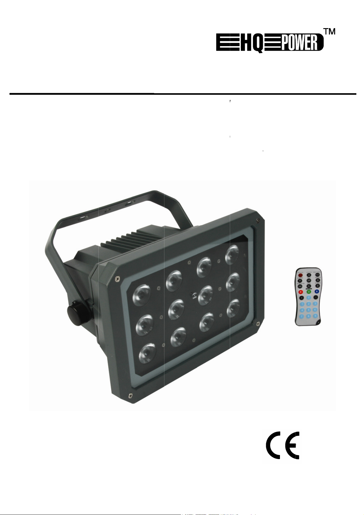
OUTD
LEDPR
PROJE
FOCO
LED-S
- 12 x
OR L
JECT
CTEU
ED P
HEIN
3W R
L
D FLO
R VO
DEL
RA E
ERF
B LED
F
DLIG
R BUI
'EXTÉ
TERIO
R FÜR
1
HT - 1
ENHU
IEUR
RES ANW
0
x 3
S - 12
- 12 L
2 LE
NDUN
BRIG
x 3 W
D RV
s RGB
IM
G
T RG
GB-L
3 W
3W
UßEN
B
LEDs
DS
EREICH
U
SER M
EBRUI
G
OTICE
N
ANUA
B
EDIEN
NUAL
ERSH
D’EMP
DEL U
NGSA
NDLE
OI
SUARI
LEIT
DING
NG
Page 2
D
oImenIf
hint
h3 Weff
OUTD
O
r
e
e
y
u
a
I
m
F
D
e
v
c
e
p
e
d
e
d
e
a
m
r
o
d
a
d
e
1
f
.
a
o
m
E
o
e
e
h
e
r
o
c
i
s
t
v
u
a
d
o
n
e
e
a
w
a
y
a
y
u
e
s
n
v
e
o
O
r
e
d
u
w
R
™
u
r
n
h
o
e
f
e
s
o
n
a
s
a
d
e
o
e
e
e
G
b
c
t
o
p
r
r
o
i
o
i
u
t
e
I
o
c
a
v
n
o
e
e
I
p
o
h
a
h
h
n
u
e
d
o
d
w
q
h
a
h
r
t
g
g
M
h
n
s
g
s
t
e
a
f
a
g
e
s
e
u
p
e
a
C
t
c
r
o
m
u
p
e
v
o
n
h
H
i
c
e
r
V
i
t
8
R
a
s
h
g
m
a
h
e
f
u
i
w
s
t
u
E
R
d
f
y
a
d
d
n
g
e
1
. Int
all resid
T
portant
vironment
in doubt,
ank you fo
T
o service.
to
the Velle
e VDPLO
T
RGB LE
ects.
2
. Saf
oducti
This
symbol on
lifec
mun
icipal wast
ld be retu
sho
contact y
r choosing
f the devi
1203RGB
Be
ele
troshocks.
OR L
nts of th
nvironm
cle could
l rules.
an® Serv
s. It offer
ty Ins
ery caref
D FL
n
Europea
ntal info
the devic
arm the e
; it shoul
ned to yo
ur local
HQPOWE
e was dam
ce and Q
is a powe
excellent
ructio
l during t
ODLI
n Union
mation a
or the pa
nvironmen
be taken
r distribut
aste dis
! Please
aged in tra
ality War
ful LED flo
colour mix
s
e installati
HT W
out this
kage indic
. Do not d
to a specia
r or to a l
osal aut
ead the m
nsit, don't
anty on t
dlight for
ng throug
n: touchi
TH RE
roduct
tes that d
ispose of t
lized comp
cal recycli
orities.
nual thoro
install or u
e final pa
outdoor u
DMX con
g live wir
OTE
isposal of
e unit (or
any for re
g service.
ughly befo
e it and c
es of this
e and feat
rol or the
s can caus
ONT
he device
batteries)
ycling. Thi
Respect t
e bringing
ntact your
anual.
res 12 hi
re-progra
life-thre
OLLE
fter its
as unsorte
device
e local
this device
dealer. Re
h-quality
med
tening
er
•
Damage c
and the d
A qualifie
•
This devic
•
a qualifie
Make sur
•
this manu
•
Do not cri
if necessa
•
Disconnec
by the plu
•
Do not lo
•
Keep the
top of the
•
Note that
•
Mechanic
•
Keep the
3
. Gen
This devic
•
VDPLOF
Lighting e
•
their lives
Do not sh
•
Select a l
•
a minimu
Use an ap
•
Ke
p this devi
Un
lug the m
aused by
aler will n
technicia
falls und
person ca
that the a
l.
p the po
y.
t the devic
g only.
k directly
evice awa
device.
damage c
l wear and
evice awa
eral G
is design
203RGB
fects are
ke the de
cation wh
distance
propriate s
ce away fr
ins lead b
isregard o
t accept r
should in
r protecti
rry out the
vailable vo
er cord a
e from the
t the light
from spl
used by u
the LEDs
from chil
idelin
d for use
hould be c
ot design
ice. Avoid
re the dev
f 0.5 m b
afety cabl
m rain an
fore open
certain g
sponsibili
tall and s
n class I.
electric c
ltage does
d protect i
mains to
source as
shing and
er modific
re not co
ren and u
s
on stage, i
nnected t
d for perm
brute forc
ice is prot
tween the
to fix the
d moisture
ng the ho
idelines in
y for any
rvice this
t is theref
nnection.
not excee
t against d
lean it or
sensitive p
dripping li
tions to t
ered by w
nauthorise
discos, t
an altern
anent ope
when ins
cted again
device’s li
device (e.
.
sing.
this manu
nsuing de
evice.
re essenti
the volta
amage. Ha
hen it is n
eople may
uids. Nev
e device i
rranty.
d users.
eatres, as
ating curr
ation: reg
alling or o
st extrem
ht output
. VDLSC7
l is not co
ects or pr
l that the
e stated i
ve an aut
ot in use.
go into ep
r put obje
not cover
well as fo
nt of 230
lar operat
erating th
heat, dus
nd any illu
or VDLSC
ered by t
blems.
device be
the speci
orised dea
andle the
leptic seiz
ts filled w
d by the
outdoor u
AC/50 Hz.
on breaks
e device.
and mois
minated s
8).
e warrant
arthed. H
ications of
ler replace
power cor
re if they
th liquid o
arranty.
e. The
will prolon
ure. Resp
rface.
ve
it
o.
ct
V
PLOF1203R
GB
2
HQPOW
R™
Page 3
• Familiarise yourself with the functions of the device before actually using it. Do not allow
operation by unqualified people. Any damage that may occur will most probably be due to
unprofessional use of the device.
• Use the original packaging if the device is to be transported.
• All modifications of the device are forbidden for safety reasons.
• Only use the device for its intended purpose. All other uses may lead to short circuits, burns,
electroshocks, crash, etc. Using the device in an unauthorised way will void the warranty.
4. Installation
• Have the device installed by a qualified person, respecting EN 60598-2-17 and all other applicable
norms.
• The carrying construction must be able to support 10 times the weight of the device for 1 hour
without deforming.
• The installation must always be secured with a secondary attachment e.g. a safety cable.
• Never stand directly below the device when it is being mounted, removed or serviced. Have a
qualified technician check the device once a year and once before you bring it into service.
• Install the device in a location with few passers-by that is inaccessible to unauthorised persons.
• Overhead mounting requires extensive experience: calculating workload limits, determining the
installation material to be used… Have the material and the device itself checked regularly. Do not
attempt to install the device yourself if you lack these qualifications as improper installation may
result in injuries.
• Adjust the desired inclination angle via the mounting bracket and tighten the bracket screws.
• Make sure there is no flammable material within a 0.5 m radius of the device.
• Have a qualified electrician carry out the electric connection.
• Connect the device to the mains with the power plug. Do not connect it to a dimming pack.
• The installation has to be approved by an expert before the device is taken into service.
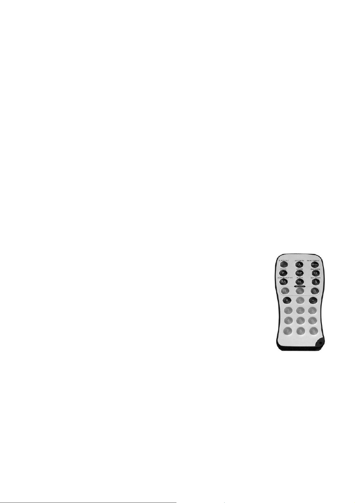
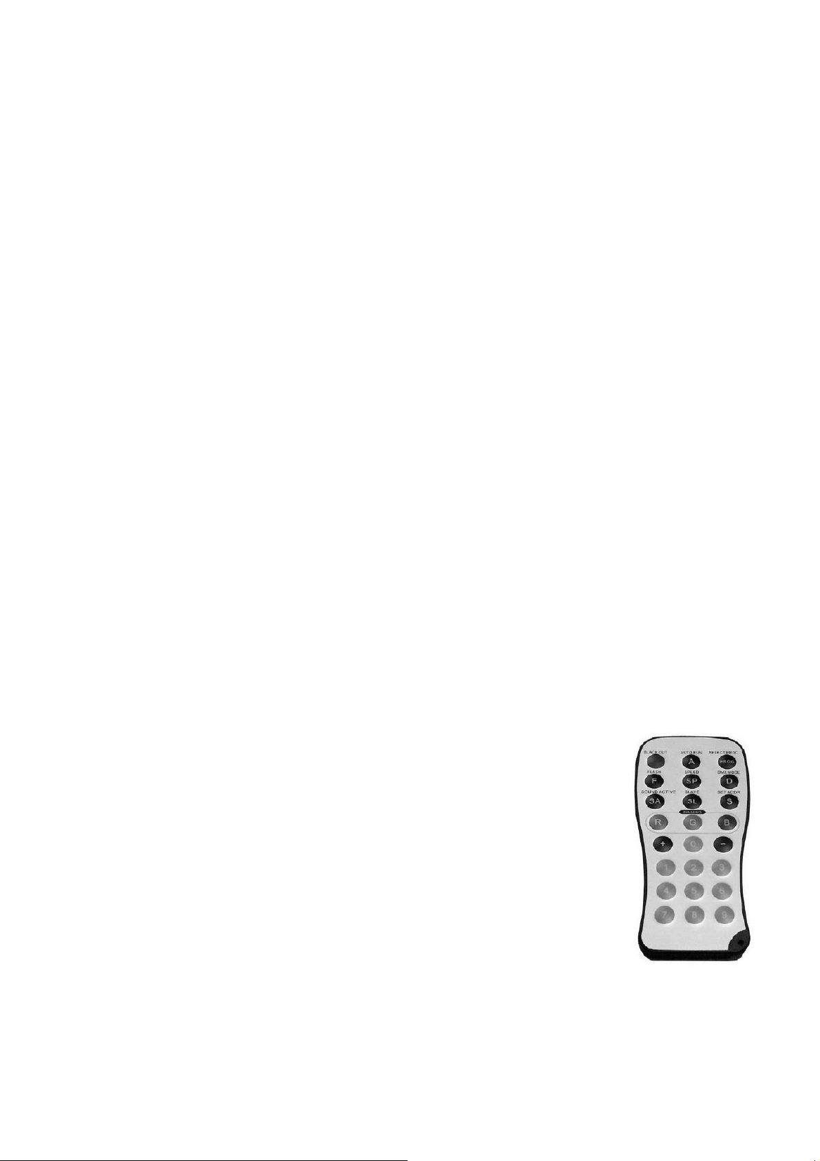
5. Remote Control Description
1. BLACK OUT button: set the light output on or off.
2. A button: set the unit to the automatic pre-programmed effects.
3. PROG button: select one of the 7 pre-programmed colour effects by
pressing the + or - button.
4. F button: flash button, set the flash on or off. Flashing can be
increased or decreased with the + and – buttons.
5. SP button: set the running speed. The button is available only in
colour jumping or colour fading, increasing or decreasing with the +
and – buttons.
6. D button: set the unit in DMX mode.
7. SA button: set the unit in sound mode (this option is unavailable for
outdoor lighting).
8. SL button: set the unit in slave mode.
9. number buttons: set the DMX address.
6. DMX
Address Setting
Set the DMX address of your VDPLOF1203RGB using the included remote control.
Examples:
Address Setting: 245
1. Press the S button; the red LEDs are on: you can start to set the address.
2. Press numeric button #2; the green LEDs are on: 2 (hundreds) setting successful.
3. Press numeric button #4; the blue LEDs are on: 4 (tens) setting successful.
4. Press numeric button #5; all the LEDs are on: complete setting successful.
VDPLOF1203RGB HQPOWER™
3
Page 4
Address Setting: 002
1. Press the S button; the red LEDs are on: you can start to set the address.
2. Press numeric button #0; the green LEDs are on: 0 (hundreds) setting successful.
3. Press numeric button #0; the blue LEDs are on: 0 (tens) setting successful.
4. Press numeric button #2; all the LEDs are on: complete setting successful.
Detailed DMX Values per Channel
Channel Function From To Description
1 Red 0 255 From 0 – 100 %
2 Green 0 255 From 0 – 100 %
3 Blue 0 255 From 0 – 100 %
4 Dimmer 0 255 From 0 – 100 %
5 Shutter
0 10 Closed
11 255 S>F strobe
DMX512 Connection
Connect the provided XLR cable to the female 3-pin XLR output of your controller and the other side
to the male 3-pin XLR input of the VDPLOF1203RGB. Multiple VDPLOF1203RGBs can be linked
through serial linking. The linking cable should be a two-core screened cable with XLR input and
output connectors.
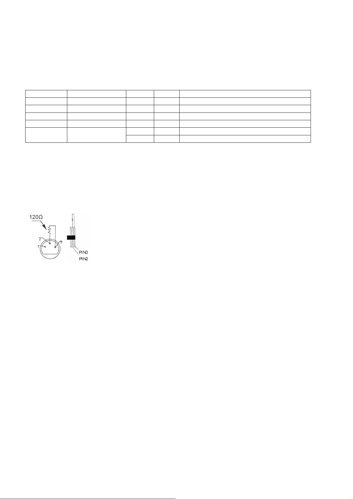
DMX512 Chain with Termination
A DMX terminator is recommended for installations where the DMX cable has
to run a long distance or is in an electrically noisy environment (e.g. discos).
The terminator prevents corruption of the digital control signal by electrical
noise. The DMX terminator is simply an XLR plug with a 120 Ω resistor
between pins 2 and 3, which is then plugged into the XLR output socket of
the last device in the chain.
Please see illustrations.
DMX Start Address Setting
All DMX-controlled devices need a digital start address so that the correct device responds to the
signals. This start address is the channel number from which the device starts to “listen” to the DMX
controller. Enter the correct number and read it from the display located on the base of the
VDPLOF1203RGB.
You can use the same starting address for a whole group of devices or enter an individual one for
every device. When all devices have the same address, all the VDPLOF1203RGBs will “listen” to
the control signal on one particular channel. In other words: changing the settings of one channel
will affect all devices simultaneously. If you set different addresses, each device will “listen” to a
separate channel number. Changing the settings of one channel will only affect the device in
question. In the case of the 5-channel VDPLOF1203RGB, you will have to set the start address of
the first VDPLOF1203RGB to 1, the second VDPLOF1203RGB to 6 (1 + 5), the third to 13 (6 + 5)
and so on.
7. Cleaning and Maintenance
1. All screws should be tightened and free of corrosion.
2. The housing, visible parts, mounting supports and the installation location (e.g. ceiling,
suspension, trussing) should not be deformed, modified or tampered with e.g. do not drill extra
holes in mounting supports, do not change the location of the connections.
3. Moving mechanic parts must not show any signs of wear and tear.
4. The electric power supply cables must not show any damage. Have a qualified technician
maintain the device.
5. Disconnect the device from the mains prior to maintenance activities.
6. Wipe the device regularly with a moist, lint-free cloth. Do not use alcohol or solvents.
7. There are no user-serviceable parts.
8. Contact your dealer for spare parts if necessary.
VDPLOF1203RGB HQPOWER™
4
Page 5

8. Technical Specifications
Power Supply 230 VAC/50 Hz
Power Consumption 50 W
Dimensions 300 x 210 x 175 mm (without bracket)
Total Weight 6 kg
LEDs 12 x 3 W RGB
Beam Angle 40°
IP Rating IP65
DMX512 Connection 3-pin XLR
Controller
Power Supply 3 V CR2025 battery
Power Consumption 60 mW
Dimensions 110 x 46 x 7 mm
Weight 22 g
Use this device with original accessories only. Velleman nv cannot be held responsible in
the event of damage or injury resulted from (incorrect) use of this device. For more info
concerning this product, please visit our website www.hqpower.com. The information in
this manual is subject to change without prior notice.
© COPYRIGHT NOTICE
This manual is copyrighted. The copyright to this manual is owned by Velleman nv. All
worldwide rights reserved. No part of this manual may be copied, reproduced, translated or reduced
to any electronic medium or otherwise without the prior written consent of the copyright holder.
VDPLOF1203RGB HQPOWER™
5
Page 6

D
L
aBeHe
ahe
e
ode
EDPR
O
e
g
s
d
n
p
r
e
1
e
d
edod
s
rope
a
o
l
e
k
n
e
u
k
e
p
o
e
o
c
o
ge
l
t
f
p
o
e
d
c
o
t
i
s
n
s
h
t
t
v
e
v
d
l
r
s
p
a
e
w
s
d
g
d
p
s
t
R
u
b
e
t
t
r
e
z
c
n
t
e
t
a
r
d
n
e
a
g
t
l
t
s
jn
e
e
E
n
d
a
w
n
g
e
d
r
r
e
n
e
e
a
n
n
r
D
t
p
S
d
e
e
h
y
c
o
h
g
e
k
e
o
o
z
g
d
a
g
o
a
A
t
a
m
a
b
e
t
s
e
n
e
n
n
t
v
e
v
C
m
N
a
m
s
m
d
n
n
l
s
b
n
s
e
p
r
t
e
e
u
e
D
n
i
n
w
e
w
n
a
s
n
a
e
e
e
m
e
o
e
i
h
n
E
e
r
n
e
d
s
v
n
e
g
1
. Inl
n alle in
A
langrijke
bt u vrag
nk u voor
D
t toestel b
VDPLOF
D
h
ogwaardig
ingebouw
2
. Veil
JECTO
iding
ezetenen
milieu-in
ymbool o
Dit
wor
t weggew
eve
tuele batt
ges
ecialiseer
naa
een lokaa
en, conta
uw aanko
schadigd
203RGB
e effecte
igheid
s voorzic
We
elijke elek
RGB-led
R VOO
van de E
ormatie
het toest
rpen, dit
rijen) nie
bedrijf te
l recyclag
teer dan
p! Lees de
ijdens het
s een krac
van elk 3
.
instru
tig bij de i
roshocks
BUIT
ropese U
etreffen
l of de ver
oestel sch
bij het ge
echtkome
punt bren
de plaats
e handlei
transport,
htige proje
W. Deze p
ties
stallatie:
e vermijd
NHUI
ie
e dit pro
pakking g
de kan to
one huis
voor rec
en. Respe
lijke aut
ing grondi
installeer
ctor voor
ojector bi
aak geen
n.
MET
uct
eft aan da
brengen a
oudelijke
clage. U
teer de pl
riteiten
g voor u h
et dan nie
ebruik bui
dt een uit
abels aan
FSTA
, als het n
an het mili
fval; het
oet dit toe
atselijke
etreffen
t toestel i
t en raadpl
enshuis e
tekende k
die onder
DSBE
zijn leve
eu. Gooi d
oet bij ee
tel naar u
ilieuwetg
e de ver
gebruik
eeg uw de
is uitgeru
eurmengi
troom sta
IENIN
scyclus
t toestel (
verdeler
ving.
ijdering.
eemt. We
ler.
t met 12
g via DMX
n om
G
n
of
d
of
•
De garant
en uw de
rechtstree
•
Laat dit t
Dit toeste
•
geschoold
•
De beschi
handleidi
•
De voedin
kabel plaa
•
Trek de st
het niet g
•
Wanneer
rookontwi
geleidelijk
•
Kijk niet r
van epile
•
Houd dit t
gevuld m
•
Schade d
garantie.
•
Mechanis
•
Houd dit t
3
. Al
Dit toeste
•
dit toestel
Lichteffec
•
langer me
Be
cherm dit
zeker u er
Ve
nen.
ie geldt ni
ler zal de
ks verban
estel insta
valt onde
technicu
bare nets
g.
gskabel m
tsen.
ekker uit h
bruikt.
het toest
keling en
aan verd
chtstreek
sie.
estel uit
t vloeistof
or wijzigin
he schade
estel uit
mene
is ontwor
enkel aan
en zijn nie
egaan.
oestel teg
an dat he
t voor sch
erantwoo
mee hou
leren en o
bescherm
moet de
anning m
g niet om
et stopcon
l voor het
een bepaa
ijnen.
in de lich
e buurt va
op het toe
en die de
en de leds
e buurt va
richtli
en voor g
luiten op
ontworpe
n regen e
toestel ni
de door h
delijkheid
en.
derhoude
ingsklasse
lektrische
g niet hog
eplooid of
act (trek
eerst geb
de geur.
bron. De li
n opspatte
tel.
gebruiker
vallen nie
n kinderen
en
bruik op
en wissels
n voor con
vochtigh
t aangesl
t negeren
fwijzen v
door een
I, wat wil
aansluitin
er zijn dan
beschadig
iet aan de
uikt, kan d
it is norm
chtbron ka
nde en dru
heeft aang
onder de
en onbev
odia en in
panning v
tinue werk
id.
ten is op
van bepaa
or defecte
geschoold
eggen dat
verzorge
de spanni
zijn. Laa
kabel!) vo
it gepaard
al en de e
n bij gevo
ppelende
ebracht aa
arantie.
egden.
disco’s als
n 230 VA
ing: regel
en stroom
lde richtlij
of proble
technicu
het toest
.
g in de s
uw deale
ordat u he
gaan met
entuele ro
lige mens
loeistoffen
n het toest
voor gebr
/50 Hz.
atige ond
ron alvor
en in dez
men die hi
.
l geaard
ecificaties
zo nodig
toestel re
en lichte
ok of geur
n leiden t
. Plaats ge
el vallen n
ik buitens
rbrekinge
ns het te
handleidi
r
oet zijn. E
achteraan
en nieuwe
inigt en al
zal
t een aan
n objecte
et onder d
uis. U ma
doen ze
g
n
e
u
al
V
PLOF1203R
GB
6
HQPOW
R™
Page 7
• Schud het toestel niet dooreen. Vermijd brute kracht tijdens de installatie en de bediening van dit
toestel.
• Installeer het toestel weg van extreme temperaturen, vochtigheid en stof. Zorg voor een
minimumafstand van 0,5 m tussen de lichtuitgang van het toestel en het belichte oppervlak.
• Maak het toestel vast met een geschikte veiligheidskabel (bv. VDLSC7 of VDLSC8).
• Leer eerst de functies van het toestel kennen voor u het gaat gebruiken. Ongeschoolde personen
mogen dit toestel niet gebruiken. Meestal is beschadiging het gevolg van onprofessioneel gebruik.
• Gebruik de oorspronkelijke verpakking wanneer u het toestel vervoert.
• Om veiligheidsredenen mag de gebruiker geen wijzigingen aanbrengen aan het toestel.
• Gebruik het toestel enkel waarvoor het gemaakt is. Andere toepassingen kunnen leiden tot
kortsluitingen, brandwonden, elektrische schokken, enz. Bij onoordeelkundig gebruik vervalt de
garantie.
4. Installatie
• Laat een geschoolde technicus dit toestel installeren conform EN 60598-2-17 en andere
toepasselijke normen.
• De constructie waaraan het toestel wordt bevestigd, moet gedurende 1 uur 10 x het gewicht van
dit toestel kunnen dragen zonder te vervormen.
• Maak het toestel ook vast met een veiligheidskabel.
• Sta nooit recht onder het toestel wanneer u het monteert, verwijdert of schoonveegt. Laat het
toestel controleren door een geschoolde technicus voor u het in gebruik neemt en laat het 1 x per
jaar volledig nakijken.
• Installeer dit toestel op een plaats waar niemand langs moet lopen, kan neerzitten of het toestel
kan aanraken.
• Een degelijke praktijkervaring is vereist voor de plaatsing van dit toestel. U moet de
maximumbelasting van de draagconstructie kunnen berekenen, weten welk constructiemateriaal
u kunt gebruiken en u moet het gebruikte materiaal en het toestel af en toe laten nakijken.
Monteer het toestel niet zelf indien u er geen ervaring mee heeft. Een slechte montage kan leiden
tot verwondingen.
• Regel de gewenste invalshoek door middel van de montagebeugel en draai de regelschroeven
stevig aan.
• Verwijder alle brandbaar materiaal in een straal van 0,5 m rond het toestel.
• Een geschoolde elektricien moet het toestel aansluiten.
• Sluit het toestel via de stekker aan op het lichtnet. Sluit het niet aan op een dimmerpack.
• De installatie moet voor het eerste gebruik gekeurd worden door een expert.
5. Omschrijving van de afstandsbediening
1. BLACK OUT: in- of uitschakelen van de lichtuitgang.
2. A: inschakelen van de ingebouwde effecten.
3. PROG: selecteren van een van de 7 ingebouwde effecten via de +- of
–-toets op de afstandbediening.
4. F: in- of uitschakelen van het flitseffect en instellen via de +- of –toets op de afstandbediening.
5. SP: instellen van de loopsnelheid. via de +- of –-toets op de
afstandbediening (enkel bij onmiddellijke of geleidelijke
kleurovergang).
6. D: inschakelen van de DMX-sturing.
7. SA: inschakelen van de muzieksturing (niet beschikbaar bij gebruik
buitenshuis).
8. SL: instellen van de slavemodus.
9. cijfertoetsen: instellen van het DMX-adres.
VDPLOF1203RGB HQPOWER™
7
Page 8

D
6
d
o
e
M
uanVDee
M
lop
g
w
aWaanop
X
l
X
:
o
o
o
o
o
o
o
o
r
g
v
0
e
-
d
s
e
d
1
g
é
d
n
n
o
e
e
e
o
e
e
e
wFun
oGroBlaDimSlu
X
n
a
t
m
e
t
n
t
e
O
h
e
e
l
h
e
e
l
p
a
p
o
e
n
e
r
e
n
b
d
e
n
s
G
e
e
e
e
l
u
g
e
n
m
M
n
R
k
e
e
v
b
e
e
m
n
n
n
n
s
e
e
a
t
t
t
a
s
s
s
s
g
%
%
%
%
o
t
i
a
d
a
a
e
o
e
e
d
e
e
d
.
n
b
v
n
d
e
t
p
e
a
g
e
i
g
o
a
L
e
s
e
y
k
E
r
e
a
h
n
t
. DM
resinstel
A
el het DM
St
orbeelden
V
Adresinst
1. Druk
2. Druk
3. Druk
4. Druk
Adresinst
1. Druk
2. Druk
3. Druk
4. Druk
detaillee
G
Kanaal
1
2
3
4
5
X512-aa
D
it de mee
Sl
dere kant
PLOF12
n 2-aderig
DMX512
a.
X-starta
D
e DMX-ge
Al
de signal
si
naal van
u
VDPLOF
U
kunt één e
rtadres in
st
nneer u é
dere woor
reageren.
-sturi
ing
-adres va
elling: 245
p S; de r
p cijferto
p cijferto
p cijferto
elling: 002
p S; de r
p cijferto
p cijferto
p cijferto
de DMX-
R
nsluiting
eleverde
an de ma
3RGB’s a
afgesche
keten me
res
tuurde to
n. Dit digi
e DMX co
203RGB.
nkel starta
even.
n enkel s
en: wann
uw VDPL
de leds lic
ts nr. 2; d
ts nr. 4; d
ts nr. 5; a
de leds lic
ts nr. 0; d
ts nr. 0; d
ts nr. 2; a
aarden
ctie
od
en
uw
mer
iter
LR-kabel
nelijke 3-
n elkaar k
rmde kabe
eindwe
en DMX ei
E
ebruikt in
g
indweersta
e
lektrische
e
et een we
a
angesloten
il
lustratie li
stellen he
ale starta
troller. Ge
dres gebru
artadres i
er u de in
F1203R
ten op: u
groene l
blauwe l
le leds lich
ten op: u
groene l
blauwe l
le leds lich
er kanaa
van
0
0
0
0
0
11
an de vro
in XLR-in
ppelen m
l met XLR i
rstand
dweersta
en omgev
nd voorko
uis. De D
rstand va
op de XL
ks.
ben een di
res is het
f het corr
iken voor
stelt, zulle
tellingen
B in met
kunt nu h
ds lichten
ds lichten
ten op: vo
kunt nu h
ds lichten
ds lichten
ten op: vo
Tot O
255 Va
255 Va
255 Va
255 Va
10 Ge
255 S>
welijke 3ang van d
t behulp v
ngang- en
d is aanbe
ing met ve
t corrupti
X eindwe
120 Ω v
-uitgang v
gitaal star
anaalnum
cte numm
en groep
n alle toes
oor 1 kan
ehulp van
t adres in
op: 2 (hon
op: 4 (tien
lledig inge
t adres in
op: 0 (hon
op: 0 (tien
lledig inge
schrijvin
0 – 100
0 – 100
0 – 100
0 – 100
loten
F strobosc
pin XLR-ui
VDPLOF
an een ser
uitgangsa
volen als d
el elektrisc
e van het
rstand is n
n pin 2 na
n het laat
adres nodi
mer van w
er in en le
oestellen
ellen ‘luist
al verand
de afstan
tellen.
derdtallen)
tallen) ing
teld.
tellen.
derdtallen)
tallen) ing
teld.
op
gang van
1203RGB
ële koppel
nsluitinge
e DMX-ka
he ruis (b
igitale co
iets meer
r 3. Deze
ste toestel
g, zodat h
arop het
s het af o
f u kunt p
ren’ naar
rt, zullen
sbedienin
ingesteld.
steld.
ingesteld.
steld.
e controll
U kunt ve
ing. Gebru
.
el vrij lan
. een disc
trolesigna
an een X
XLR-stekk
in de reek
t juiste to
oestel ‘luis
de displa
r toestel e
hetzelfde
lle toestell
.
r en de
rscheidene
k daarvoo
is of word
theek). D
l door
-stekker
r wordt d
. Zie de
stel reage
tert’ naar
onderaa
en nieuw
anaal. Me
en er tegel
t
n
ert
et
ijk
V
PLOF1203R
GB
8
HQPOW
R™
Page 9

Wanneer u verschillende adressen instelt, dan luistert elk toestel naar een ander kanaal. Met andere
woorden: wanneer u de instellingen van een kanaal verandert, zal enkel het toestel op dat kanaal
reageren.
In het geval van de 5-kanaals VDPLOF1203RGB, zult u het startadres van het eerste toestel op 1
moeten instellen, van het tweede toestel op 6 (1 + 5), van het derde op 13 (6 + 5), enz.
7. Reiniging en onderhoud
1. Alle gebruikte schroeven moeten goed zijn aangespannen en mogen geen sporen van roest
vertonen.
2. De behuizing, de lenzen, de montagebeugels en de montageplaats (bv. het plafond of het
gebinte) mogen niet vervormd zijn of aangepast worden (geen extra gaten in montagebeugels,
aansluitingen niet verplaatsen, enz.)
3. Mechanisch bewegende delen mogen geen sporen van slijtage vertonen en mogen niet
onregelmatig bewegen.
4. De voedingskabels mogen niet beschadigd zijn. Laat het toestel onderhouden door een
geschoolde technicus.
5. Ontkoppel het toestel van het lichtnet voor u aan onderhoudswerkzaamheden begint.
6. Maak het toestel geregeld schoon met een vochtige, niet pluizende doek. Gebruik geen alcohol of
solvent.
7. De gebruiker mag geen onderdelen vervangen.
8. Bestel eventuele reserveonderdelen bij uw dealer.
8. Technische specificaties
Voeding 230 VAC/50 Hz
Verbruik 50 W
Afmetingen 300 x 210 x 175 mm (zonder beugel)
Gewicht 6 kg
Leds 12 x 3 W RGB
Kijkhoek 40°
IP-norm IP65
DMX512-aansluiting 3-pin XLR
Controller
Voeding 3 V-batterij type CR2025
Verbruik 60 mW
Afmetingen 110 x 46 x 7 mm
Gewicht 22 g
Gebruik dit toestel enkel met originele accessoires. Velleman nv is niet aansprakelijk voor
schade of kwetsuren bij (verkeerd) gebruik van dit toestel. Voor meer informatie over dit
product, zie www.hqpower.com. De informatie in deze handleiding kan te allen tijde
worden gewijzigd zonder voorafgaande kennisgeving.
© AUTEURSRECHT
Velleman nv heeft het auteursrecht voor deze handleiding.
Alle wereldwijde rechten voorbehouden. Het is niet toegestaan om deze handleiding of gedeelten
ervan over te nemen, te kopiëren, te vertalen, te bewerken en op te slaan op een elektronisch
medium zonder voorafgaande schriftelijke toestemming van de rechthebbende.
VDPLOF1203RGB HQPOWER™
9
Page 10

D
P
uDeproEn
o
ales
ROJE
C
r
n
a
s
t
s
t
s
e
u
e
a
t
1
é
é
s
Être
c
t
b
v
n
e
t
n
c
r
e
m
g
e
p
m
e
é
t
e
e
e
u
o
R
o
n
v
e
e
r
r
c
d
e
e
c
é
o
o
m
a
e
à
q
o
d
f
t
r
s
t
e
é
N
e
D
p
e
m
e
s
o
h
a
s
s
t
e
u
n
e
t
d
s
o
o
o
r
e
g
a
o
e
n
É
p
o
v
i
a
m
c
n
é
t
t
g
r
r
e
s
t
f
d
a
n
U
u
a
s
e
n
d
é
v
l
a
u
e
t
m
e
a
n
s
n
n
E
m
e
t
r
a
e
s
s
d
u
e
a
a
s
d
d
v
1
e
a
e
r
p
d
a
,
d
é
e
u
B
d
t
f
r
s
e
é
e
e
E
D
v
e
à
l
t
n
e
e
s
z
1
. Int
x réside
A
s inform
tection d
cas de q
us vous r
N
se
rvice de l’
nsulter vo
co
VDPLOF
Le
ute qualit
h
effets pr
2
. Pre
oducti
ts de l'U
tions en
Ce
ymbole su
peu
polluer l'
pile
éventuell
trai
era l’appa
un
ervice de
l’environn
mercions
ppareil. Si
re revend
203RGB
. Ce proje
programm
prudent l
éle
trochocs
TEU
estions,
cripti
DEL
n
ion euro
ironnem
r l'appareil
nvironne
s) parmi l
eil en que
ecyclage l
ement.
ontacter
e votre ac
l’appareil
ur.
st un puis
teur offre
s.
ns de
rs de l’ins
ortels.
'EXT
éenne
ntales im
ou l'embal
ent. Ne pa
s déchets
tion. Renv
cal. Il con
les autor
at ! Lire l
été endo
ant proje
un excelle
écurit
allation :
RIE
ortantes
lage indiq
s jeter un
municipau
yer les éq
ient de re
tés local
présente
magé pe
teur DEL d
t mixage
oucher un
R AV
concerna
e que l’éli
ppareil él
x non suje
uipements
pecter la
s pour éli
notice atte
dant le tr
’extérieur
e couleurs
câble sou
C TÉL
nt ce pro
ination d’
ctrique ou
s au tri sé
usagés à
églementa
mination.
ntivement
nsport, ne
t intègre
depuis un
tension p
ÉCOM
uit
un apparei
électroniq
lectif ; une
otre fourn
tion locale
avant la m
pas l’insta
2 DEL RV
pilotage D
ut causer
MAN
l en fin de
e (et des
déchèteri
isseur ou
relative à
ise en
ller et
de 3 W
MX ou dep
es
E
ie
a
uis
•
La garanti
notice et
résultent.
•
Confier l’i
Cet appar
•
terre. Un
La tensio
•
cette noti
Le câble d
•
renouvele
•
Débranch
non pas le
•
La premiè
C’est nor
•
Ne pas re
certains g
•
Tenir l’ap
un liquide
•
Les dom
la garanti
•
L’usure m
•
Garder vo
3
. Dir
Cet appar
•
usage à l’
•
Un effet l
prolonger
V
PLOF1203R
Pro
éger l’app
Dé
rancher le
e ne s’appl
otre reven
stallation
il ressort
echnicien
réseau ne
e.
’alimentati
le câble
r l’appareil
câble.
re mise en
al. Toute
arder direc
ns.
areil à l’éc
sur l’appa
ages occa
.
canique e
re project
ctives
il a été d
xtérieur.
mineux n’
nt sa vie.
GB
reil contr
câble d'ali
ique pas a
deur décli
t l’entreti
la classe
ualifié doi
peut pas
n ne peut
’alimentati
s’il n’est pa
service pe
umée ou
ement la s
art d’éclab
eil.
ionnés pa
les DEL n
ur hors d
énér
veloppé p
e connect
st pas co
la pluie e
mentation
x domma
era toute
n à un pe
de protecti
établir la
épasser la
pas être r
on si néce
utilisé ou
ut s’accom
deur dispa
urce lumin
ussures e
des modi
e tombent
la portée
les
ur usage
r cet app
çu pour u
l’humidit
avant d'ou
es surven
esponsabi
sonnel qu
on I, ce q
connexion
tension m
plissé ou
saire.
pour le net
pagner d’u
raîtra grad
euse com
de jailliss
ications à l
pas sous l
de person
ans des di
reil qu’à u
e opératio
10
.
rir le boîti
us en négli
ité pour le
lifié.
i implique
électrique.
entionnée
ndommag
oyer. Tirer
n peu de f
uellement.
e ceci peut
ments. N
’appareil p
garantie.
es non qu
cothèque
e source
continue.
er.
geant cert
problèm
que l’appa
ans les s
é. Deman
la fiche pou
mée ou d’
entraîner d
jamais pl
r le client
lifiées et
et des th
e courant
Des paus
ines direc
s et les dé
eil doit êt
écification
er à votre
r débranch
une odeur
es crises d’
cer d’obje
ne tombe
e jeunes
âtres tout
CA de 230
s régulièr
ives de ce
auts qui e
e mis à la
à la fin d
revendeur
r l'appareil
particulièr
pilepsie ch
t contenan
nt pas sou
nfants.
comme un
VCA/50 H
s
HQPOW
te
de
;
.
ez
t
.
R™
Page 11

• Éviter de secouer l’appareil et traiter l’appareil avec circonspection pendant l’installation et
l’opération.
• Choisir un endroit où l’appareil est protégé contre la poussière, l’humidité et des températures
extrêmes. Respecter une distance minimum de 0,5 m entre la sortie lumière de l’appareil et la
surface illuminée.
• Fixer l’appareil à l’aide d’un câble de sécurité adéquat (p.ex. VDLSC7 ou VDLSC8).
• Se familiariser avec le fonctionnement de l’appareil avant de l’utiliser. Ne pas permettre pas aux
personnes non qualifiées d’opérer cet appareil. La plupart des dégâts sont causés par un usage
non professionnel.
• Transporter l’appareil dans son emballage originel.
• Toute modification de l’appareil est interdite pour des raisons de sécurité.
• N’utiliser votre projecteur qu’à sa fonction prévue. Tout autre usage peut causer des courts-
circuits, des brûlures, des électrochocs etc. Un usage impropre annule d'office la garantie.
4. Installation
• Un technicien qualifié doit installer l’appareil en respectant EN 60598-2-17 et toute autre norme
applicable.
• La construction portante de l’appareil doit être capable de supporter 10 x le poids de l’appareil
pendant une heure, sans qu’une déformation de la construction en résulte.
• Fixer votre projecteur à l’aide d’un câble de sécurité (sécurité supplémentaire).
• Éviter de vous positionner en dessous de l’appareil pour l’enlever ou lors du montage ou du
nettoyage. Un technicien qualifié doit réviser l’appareil avant la mise en service. Organiser une
révision minutieuse annuelle.
• Installer l’appareil à un endroit où personne ne peut passer ou s’asseoir et où personne ne peut le
toucher.
• L’installation de cet appareil exige une solide expérience pratique : le calcul de la charge max. de
la construction, les matériaux d’installation requis etc. De temps en temps, un technicien qualifié
doit vérifier la construction portante et l’appareil même. Ne pas essayer d’installer cet appareil
vous-même si vous n’avez pas les qualifications requises ; une installation incorrecte peut
entraîner des blessures.
• Déterminer l’angle d’inclinaison au moyen de l’étrier de montage et serrer les vis de montage.
• Enlever tout matériau inflammable dans un rayon de 0,5 m autour de l’appareil.
• Un électricien qualifié doit établir la connexion électrique.
• Brancher l’appareil sur le réseau électrique par la fiche d’alimentation. Ne pas le brancher sur un
bloc de puissance.
• Un expert doit approuver l’installation avant qu’elle puisse être prise en service.
5. Description de la télécommande
1. BLACK OUT : activation/désactivation de la sortie lumineuse.
2. A : activation/désactivation des programmes intégrés.
3. PROG: sélection d’un des 7 programmes et configuration depuis les
touches +/- sur la télécommande.
4. F : activation/désactivation des éclats et configuration depuis les
touches +/- sur la télécommande.
5. SP : configuration de la vitesse depuis les touches +/- sur la
télécommande (uniquement lors d’une transition de couleurs subite
ou graduelle).
6. D : activation du mode de pilotage DMX.
7. SA : activation du mode de pilotage par le son (option non disponible
lors d’une utilisation en extérieur).
8. SL : activation du mode esclave.
9. touches numériques : adressage DMX.
VDPLOF1203RGB HQPOWER™
11
Page 12

6. Pilotage DMX
Adressage
Adresser votre VDPLOF1203RGB depuis la télécommande.
Exemples :
Adresse : 245
1. Enfoncer la touche S ; les DEL rouges s’allument : le mode d’adressage est activé.
2. Enfoncer la touche numérique n° 2 ; les DEL vertes s’allument : adressage 2 (centaines).
3. Enfoncer la touche numérique n° 4 ; les DEL bleues s’allument : adressage 4 (dizaines).
4. Enfoncer la touche numérique n° 5 ; toutes les DEL s’allument : adressage complet.
Adresse : 002
1. Enfoncer la touche S ; les DEL rouges s’allument : le mode d’adressage est activé.
2. Enfoncer la touche numérique n° 0 ; les DEL vertes s’allument : adressage 0 (centaines).
3. Enfoncer la touche numérique n° 0 ; les DEL bleues s’allument : adressage 0 (dizaines).
4. Enfoncer la touche numérique n° 2 ; toutes les DEL s’allument : adressage complet.
Valeurs DMX détaillées par canal
Canal Fonction De À Description
1 Rouge 0 255 De 0 – 100 %
2 Vert 0 255 De 0 – 100 %
3 Bleu 0 255 De 0 – 100 %
4 Graduateur 0 255 De 0 – 100 %
5 Obturateur
Connexion DMX512
Connecter le câble à fiche XLR inclus à la sortie XLR femelle à 3 broches de votre contrôleur et
l’autre fiche XLR mâle à 3 broches à l’entrée du VDPLOF1203RGB. Il est possible de relier plusieurs
VDPLOF1203RGB à partir d’une connexion sérielle. Utiliser un câble de connexion blindé à 2
conducteurs avec des connecteurs d’entrée et de sortie XLR.
Connexion DMX512 avec une résistance de terminaison
Une résistance de terminaison DMX est à recommander si le câble DMX doit
couvrir une grande distance ou s’il est utilisé dans un environnement avec
beaucoup de bruit électrique (p.ex. une discothèque). La résistance de
terminaison prévient la corruption du signal de contrôle numérique par le
bruit électrique. La résistance de terminaison DMX n’est rien d’autre qu’une
fiche XLR avec une résistance de 120 Ω de broche 2 vers broche 3 (voir
illustration à gauche). Cette fiche XLR est connectée à la sortie XLR du
dernier appareil de la série.
Adresse de départ DMX
Tous les appareils pilotés par un signal DMX demandent une adresse de départ DMX pour assurer
que les appareils corrects réagissent sur les signaux de contrôle. Cette adresse de départ numérique
indique le numéro de canal sur lequel l’appareil écoute le contrôleur DMX. Déterminer cette adresse
avec les interrupteurs DIP au dos de l’appareil. Vous avez le choix entre une seule adresse de départ
pour toute une série d’appareils ou une adresse de départ par appareil. Dans le cas d’une seule
adresse, tous les appareils « écouteront » les mêmes signaux, sur un seul canal. Tous les appareils
seront donc influencés lorsque vous changez les réglages d’un seul canal. Avec des adresses de
départ individuelles, chaque appareil « écoutera » son propre canal. Par conséquent, un ajustement
des réglages d’un canal n’influence que l'appareil sur ce canal. Pour le VDPLOF1203RGB à 5
0 10 Fermé
11 255 Stroboscope S>F
VDPLOF1203RGB HQPOWER™
12
Page 13

canaux, l’adresse de départ du premier appareil est 1, du deuxième 6 (1 + 5), du troisième 13 (6 +
5), etc.
7. Nettoyage et entretien
1. Serrer les écrous et les vis et vérifier qu’ils ne rouillent pas.
2. Le boîtier, les lentilles, les supports de montage et la construction portante ne peuvent pas être
déformés, adaptés ou bricolés p.ex. pas de trous additionnels dans un support, ne pas déplacer
les connexions etc.
3. Les parties mécaniques mobiles ne peuvent pas être usées ou bouger de manière irrégulière.
4. Les câbles d'alimentation ne peuvent pas être endommagés. Un technicien qualifié doit entretenir
l’appareil.
5. Débrancher l’appareil avant de le nettoyer.
6. Essuyer l’appareil régulièrement avec un chiffon humide non pelucheux. Éviter l’usage d’alcool et
de solvants.
7. Il n’y a aucune pièce maintenable par l’utilisateur.
8. Commander des pièces de rechange éventuelles chez votre revendeur.
8. Spécifications techniques
Alimentation 230 VCA/50 Hz
Consommation 50 W
Dimensions 300 x 210 x 175 mm (sans étrier)
Poids 6 kg
DEL 12 x 3 W RVB
Angle de rayonnement 40°
Indice IP IP65
Connexion DMX51 XLR à 3 broches
Contrôleur
Alimentation pile 3 V type CR2025
Consommation 60 mW
Dimensions 110 x 46 x 7 mm
Poids 22 g
N’employer cet appareil qu’avec des accessoires d’origine. SA Velleman ne sera
aucunement responsable de dommages ou lésions survenus à un usage (incorrect) de cet
appareil. Pour plus d’information concernant cet article, visitez notre site web
www.hqpower.com. Toutes les informations présentées dans cette notice peuvent être
modifiées sans notification préalable.
© DROITS D’AUTEUR
SA Velleman est l’ayant droit des droits d’auteur pour cette notice.
Tous droits mondiaux réservés.
Toute reproduction, traduction, copie ou diffusion, intégrale ou partielle, du contenu de cette notice
par quelque procédé ou sur tout support électronique que se soit est interdite sans l’accord préalable
écrit de l’ayant droit.
VDPLOF1203RGB HQPOWER™
13
Page 14

D
mme
ran
a
3Wlos
FOCO
r
d
s
s
a
a
d
h
s
a
r
t
d
s
c
e
a
a
e
e
t
T
p
i
g
o
t
a
o
e
A
ó
c
c
p
u
n
e
a
n
n
s
u
a
o
e
e
o
T
r
m
o
e
t
o
F
ge
o
E
X
u
b
a
d
s
D
a
r
s
l
d
r
n
a
e
s
é
r
d
t
n
c
B
s
p
s
e
O
d
b
r
a
a
3
f
o
a
d
e
h
n
n
a
s
s
m
e
e
a
s
e
p
E
a
o
a
r
c
u
n
c
p
i
e
e
p
a
e
n
s
a
d
a
e
o
a
p
e
r
n
A
r
l
n
n
e
u
s
s
u
n
d
g
e
a
a
u
n
n
o
e
A
e
s
D
e
e
c
o
a
a
e
b
c
r
c
e
s
b
c
o
é
a
s
e
C
n
r
A
u
v
a
s
d
r
D
o
a
n
p
a
.
e
e
h
r
s
u
.
E
o
e
o
o
1
. Int
los ciuda
A
portante
I
dio ambie
Si
tiene du
acias por
G
tes de usa
m
rcha. Si e
VDPLOF1
El
de alta c
efectos p
2
. Ins
Este
podrí
basur
su dis
Cui
cab
LED P
oducci
anos de l
informa
ímbolo en
n dañar el
doméstic
tribuidor o
nte.
as, conta
aber com
rlo. Verifiq
el caso,
203RGB e
lidad. Est
eprogram
ruccio
ado dura
les con un
RA E
n
a Unión E
iones so
este apara
medio am
a; debe ir
a la unida
te con la
rado el V
e si el ap
o conecte
s un poten
proyecto
dos.
es de
te la insta
voltaje pel
TERI
ropea
re el me
to o el em
biente. No
una emp
de recicl
autorid
PLOF120
rato ha su
el aparato
te proyect
ofrece un
eguri
ación: pu
igroso.
RES C
io ambie
alaje indi
tire este a
esa espec
je local. R
des local
RGB! Lea
rido algún
a la red y
r LED par
excelent
ad
de sufrir u
ON M
te conce
a que, si ti
arato (ni l
alizada en
spete las
s para re
atentame
daño en e
óngase e
el uso en
mezcla d
a peligros
NDO
niente a
ra las mue
as pilas, si
reciclaje.
eyes local
siduos.
te las inst
l transport
contacto
exteriores
colores p
a descarg
DIST
ste prod
tras inser
las hubier
evuelva e
s en relaci
rucciones
antes de
on su dist
con 12 LE
r un contr
eléctrica
NCIA
cto
ibles,
) en la
te aparat
ón con el
el manual
la puesta
ibuidor.
s RGB de
l DMX o p
l tocar los
a
n
r
•
Los daños
garantía y
•
La instala
No conect
•
que el ap
Este apar
•
puesto a t
•
Asegúres
No aplast
•
superficie
•
Desconec
limpiarlo.
Puede pro
•
olor desa
•
No mire d
•
No expon
p.ej. un fl
•
Los daños
•
El desgas
•
Mantenga
3
. Nor
Este apar
•
permitido
230VCA/5
•
No ha sid
prolongar
No agite
•
No
exponga e
De
conecte el
causados
su distrib
ión y el m
el aparat
rato llegu
to perten
ierra. La c
de que la
el cable d
afilada. Si
e siempre
ire siemp
ducirse hu
arecerá p
rectament
a el apara
rero, en e
causados
e mecánic
el VDPLO
mas
to ha sido
para el us
0Hz.
diseñado
la vida del
l aparato.
te equipo
cable de a
por descui
idor no se
ntenimie
si ha est
a la temp
ce a la cla
nexión el
tensión de
e alimenta
es necesa
el aparato
e del ench
o u olor
co a poco.
a la fuen
o a ningú
l aparato.
por modifi
y los LED
1203RG
nerale
diseñado
en interio
para un u
aparato.
vite usar
a lluvia o
limentació
o de las i
á respons
to deben
do expue
ratura a
e de prot
ctrica deb
red no se
ción y prot
io, pida a
si no va a
ufe para d
urante la
e de luz.
tipo de s
aciones n
s no están
lejos del
ara uso p
res y coné
o ininterru
xcesiva f
umedad.
de la red
struccione
ble de nin
er realizad
to a grand
biente.
cción I. Po
llevarse a
mayor qu
éjalo contr
u distribui
usarlo dur
sconectar
rimera pu
sto puede
lpicadura
autorizad
cubiertos
lcance de
ofesional
telo a una
mpido. Int
erza dura
antes de a
de seguri
gún daño
s por per
es cambio
r lo tanto,
cabo por
e la tensió
posibles
or reempl
nte un lar
el cable d
sta en m
causar un
goteo. N
s, no está
or la gara
personas
n una disc
fuente de
oduzca fr
te la instal
brir la caj
dad de est
otros pro
onal espe
de tempe
es esencial
n técnico
indicada
años cau
azar el ca
o periodo
red, nun
rcha. Es n
taque epil
nca pong
n cubierto
tía.
o capacita
teca, un t
corriente
cuenteme
ación y la
.
manual i
lemas res
ializado.
ratura. Es
que el ap
ualificado
n las esp
ados por a
le de alim
de tiempo
a del propi
rmal y el
ptico.
un objeto
por la ga
das y niño
atro, etc.
A de máx.
te una pa
eparación
validarán
ultantes.
ere hasta
rato esté
cificacione
lgún tipo d
ntación.
o antes de
o cable.
umo o el
con líquid
antía.
.
Sólo está
sa para
su
s.
e
,
V
PLOF1203R
GB
14
HQPOW
R™
Page 15

• Seleccione un lugar de montaje donde el aparato no esté expuesto a polvo, humedad y
temperaturas extremas. Respete una distancia de mín. 0.5m entre la salida de luz y el área
iluminada.
• Fije el aparato con un cable de seguridad adecuado (p.ej. VDLSC7 o VDLSC8).
• Familiarícese con el funcionamiento del aparato. Sólo personas cualificadas pueden manejar este
aparato. La mayoría de los daños son causados por un uso inadecuado.
• Transporte el aparato en su embalaje original.
• Por razones de seguridad, las modificaciones no autorizadas del aparato están prohibidas.
• Utilice sólo el VDPLOF1203RGB para aplicaciones descritas en este manual a fin de evitar p.ej.
cortocircuitos, quemaduras, descargas eléctricas, etc. Un uso desautorizado puede causar daños
y anula la garantía completamente.
• Un experto debe probar la instalación antes de la puesta en marcha.
4. Instalación
• Respete la directiva EN 60598-2-17 y toda norma nacional antes de instalar el aparato. La
instalación debe ser realizada por un técnico especializado.
• El soporte donde irá el aparato, debe ser capaz de sostener 10 veces el peso de éste durante una
hora, sin que se produzca una deformación de dicho soporte.
• Fije siempre el VDPLOF1203RGB con un cable de seguridad (seguridad adicional).
• Evite ponerse debajo del aparato durante el montaje, la limpieza, etc. Un técnico especializado
debe revisar el aparato antes de la puesta en marcha. Después, debe revisarlo una vez al año.
• Instale el aparato fuera del alcance de personas no autorizadas y en un lugar con poca gente.
• La instalación de este aparato exige una sólida experiencia práctica: debe poder calcular la carga
máx. del soporte, debe conocer los materiales necesarios para la instalación, etc. De vez en
cuando, una verificación de la estructura y del aparato mismo debe ser llevada a cabo por un
técnico especializado. No intente instalar este aparato si no tiene las cualificaciones requeridas;
una instalación incorrecta puede causar lesiones.
• Ajuste el ángulo de inclinación a su gusto mediante un soporte de montaje y fije los tornillos del
soporte.
• Quite todo material inflamable en un radio de 0.5m alrededor del aparato.
• Pregunte a un electricista cómo hacer la conexión eléctrica.
• Conecte el aparato a la red eléctrica con la conexión de alimentación. Normalmente, no se
conectan efectos luminosos a dimmer packs (reguladores).
• Un experto debe probar la instalación antes de la puesta en marcha.
5. Descripción del mando a distancia
1. BLACK OUT: activación/desactivación de la salida luminosa.
2. A: activación/desactivación de los programas incorporados.
3. PROG: selección de uno de los 7 programas y configuración con las
teclas +/- del mando a distancia.
4. F: activación/desactivación de los destellos y configuración con las
teclas +/- del mando a distancia.
5. SP: configuración de la velocidad con las teclas +/- del mando a
distancia (sólo durante un cambio de color inmediato o gradual).
6. D: activación del modo de control DMX.
7. SA: activación del modo de control por la música (esta opción no
está disponible al utilizar el aparato en exteriores).
8. SL: activación del modo esclavo.
9. teclas con las cifras: dirección DMX.
VDPLOF1203RGB HQPOWER™
15
Page 16

6. Control DMX
Dirección
Introduzca la dirección por el mando a distancia.
Ejemplos:
Dirección: 245
1. Pulse la tecla S; los LEDs rojos se iluminan: el modo para seleccionar una dirección está
activado.
2. Pulse la tecla con el n° 2; los LEDs verdes se iluminan: dirección 2 (centenas).
3. Pulse la tecla con el n° 4; los LEDs azules se iluminan: dirección 4 (decenas).
4. Pulse la tecla con el n° 5; todos los LEDs se iluminan: está terminado la introducción de la
dirección.
Adresse : 002
1. Pulse la tecla S; los LEDs rojos se iluminan: el modo para seleccionar una dirección está
activado.
2. Pulse la tecla con el n° 0; los LEDs verdes se iluminan: dirección 0 (centenas).
3. Pulse la tecla con el n° 0; los LEDs azules se iluminan: dirección 0 (decenas).
4. Pulse la tecla con el n° 2; todos los LEDs se iluminan: está terminado la introducción de la
dirección.
Valores DMX detallados por canal
Canal Función De A Descripción
1 Rojo 0 255 De 0 – 100 %
2 Verde 0 255 De 0 – 100 %
3 Azul 0 255 De 0 – 100 %
4 Dimmer 0 255 De 0 – 100 %
5 Shutter
Conexión DMX512
Conecte el cable con conector XLR (incl.) a la salida XLR hembra de 3 polos del controlador y el otro
conector XLR macho de 3 polos a la entrada del VDPLOF1203RGB. Es posible conectar varios
VDPLOF1203RGB en serie. Use un cable blindado de doble hilo conductor con conectores XLR de
entrada y de salida.
Conexión DMX-512 con una terminación DMX
Se recomienda una terminación si el cable DMX debe cubrir una gran
distancia o si se usa en un medio ambiente con mucho ruido eléctrico (ej.
una discoteca). La terminación impide que el ruido eléctrico corrompa la
señal de control numérico. La terminación DMX no es más que un conector
XLR con una resistencia de 120Ω de polo 2 a polo 3. Este conector XLR está
conectado a la salida XLR del último aparato de la serie. Véase la figura a la
izquierda.
Dirección inicial DMX
Si se usa una señal DMX, cada aparato tiene su propia dirección inicial DMX para asegurar que los
aparatos reaccionen a las señales de control correctas. Esta dirección inicial digital es el primer canal
en el cual el aparato reaccionará a las señales DMX del controlador DMX. Determine esta función con
los interruptores DIP de la parte trasera del aparato.
Es posible elegir entre una sola dirección inicial para toda una serie de aparatos o una dirección
inicial por aparato. Con una sola dirección inicial para una serie de aparatos, todos los aparatos
reaccionarán sincronizadamente a la misma señal. Por lo tanto, cambiar los ajustes de un solo canal
VDPLOF1203RGB HQPOWER™
0 10 Cerrado
11 255 Estroboscopio S>F
16
Page 17

afecta a los ajustes de todos los canales. Con varias direcciones iniciales, cada aparato reaccionará
independientemente. Por lo tanto, cambiar los ajustes de un solo canal sólo afecta al canal en
cuestión.
En el caso del VDPLOF1203RGB de 5 canales, la dirección inicial del primer aparato es 1.
Introduzca 6 (1 + 5) para el segundo aparato, introduzca 13 (6 + 5) para el tercer aparato, etc.
7. Limpieza y mantenimiento
1. Apriete bien las tuercas y los tornillos y verifique que no hay señales de oxidación.
2. No modifique la caja, los soportes y las ópticas p.ej. no taladre agujeros adicionales en un
soporte o no modifique las conexiones, etc.
3. Las partes móviles no pueden mostrar ningún rastro de desgaste y deben estar bien equilibradas.
4. No dañe los cables de alimentación. Contacte con un técnico especializado para instalar el
aparato.
5. Desconecte el aparato de toda fuente antes de limpiarlo.
6. Limpie el aparato regularmente con un paño húmedo. Evite el uso de alcohol y de disolventes.
7. El usuario no habrá de efectuar el mantenimiento de ninguna pieza.
8. Contacte con su distribuidor si necesita piezas de recambio.
8. Especificaciones
Alimentación 230 VCA/50 Hz
Consumo 50 W
Dimensiones 300 x 210 x 175 mm (sin soporte de montaje)
Peso 6 kg
LED 12 x 3 W RGB
Ángulo del haz 40°
Grado de protección IP IP65
Conexión DMX51 XLR con 3 polos
Controlador
Alimentación 230 VCA/50 Hz
Consumo pila de 3 V tipo CR2025
Consumo 60 mW
Dimensiones 110 x 46 x 7 mm
Peso 22 g
Utilice este aparato sólo con los accesorios originales. Velleman NV no será responsable
de daños ni lesiones causados por un uso (indebido) de este aparato. Para más
información sobre este producto, visite nuestra página web www.hqpower.com. Se
pueden modificar las especificaciones y el contenido de este manual sin previo aviso.
© DERECHOS DE AUTOR
Velleman NV dispone de los derechos de autor para este manual del usuario.
Todos los derechos mundiales reservados. Está estrictamente prohibido reproducir, traducir, copiar,
editar y guardar este manual del usuario o partes de ello sin previo permiso escrito del derecho
habiente.
VDPLOF1203RGB HQPOWER™
17
Page 18

D
L
n
eweFaBe
i
emiüb
ED-S
C
f
w
m
e
u
e
e
s
p
e
n
d
F
w
h
eSpa
h
e
n
e
S
a
e
n
e
a
S
t
s
e
e
g
e
c
e
W
g
r
a
a
m
S
e
t
s
W
s
h
d
a
ü
e
ä
e
h
a
ä
d
r
d
d
t
t
c
e
d
R
M
s
n
o
b
n
c
n
Ü
D
e
i
n
t
v
o
a
n
f
S
n
t
g
t
c
e
s
e
D
t
A
R
o
s
o
e
n
e
S
d
n
u
e
e
d
i
r
h
a
e
e
c
g
e
e
t
n
r
N
c
u
t
t
r
!
a
c
w
e
e
s
n
i
e
z
i
s
t
e
n
e
m
p
V
u
G
t
s
r
y
h
n
i
n
s
n
w
e
a
d
d
l
r
e
n
f
r
d
c
t
U
d
a
;
s
e
n
e
u
e
r
e
s
r
h
e
r
N
r
r
i
g
r
e
e
ß
r
h
k
e
s
e
e
b
n
D
c
e
E
H
s
e
F
g
e
t
t
e
HEIN
ERFE
FÜR
NWE
DUN
IM A
ßENB
EREIC
1
. Ein
alle Ein
A
W
ichtige U
rden. Die
w
rden. Res
lls Zweif
hörde.
r bedanke
W
In
betriebnah
se
in, verwen
r VDPLO
D
t 12 hoch
er DMX od
2
. Sic
Dies
Prod
Einh
verw
Sei
füh
ührun
ohner de
weltinfo
s Symbol
ktes nach
it (oder ve
ndeten B
e Einheit
ektieren
l bestehe
uns für d
me sorgfäl
en Sie da
1203RGB
ertigen 3
er eingeba
erheit
n Sie wäh
nnung ste
ren.
r Europäi
matione
uf dem Pr
seinem Le
rwendeten
tterien mü
uss an de
ie die örtli
n, wende
n Kauf de
ig durch.
Gerät nic
ist ein leis
-RGB-LE
ute Effekt
hinwe
rend der I
enden Lei
IT FE
chen Uni
über die
dukt oder
enszyklus
Batterien)
ssen von e
Händler
hen Umw
Sie sich
s VDPLOF
berprüfen
ht und we
tungsstark
s. Dieser
.
se
stallation
ungen kö
NBED
n
es Produ
der Verpa
der Umwe
nicht als
iner spezia
der ein ör
ltvorschrif
für Entso
1203RGB
Sie, ob Tr
den Sie si
r Schein
cheinwerf
es Geräte
nte zu leb
IENUN
kt
kung zeig
lt Schaden
nsortierte
lisierten Fi
liches Rec
en.
gungsric
Lesen Sie
nsportsch
h an Ihre
erfer für d
r bietet ei
s sehr vor
nsgefährli
G
an, dass
zufügen k
Hausmüll
ma zweck
cling-Unt
tlinien a
diese Bedi
äden vorli
Händler.
e Anwend
e ausgez
ichtig: das
chen elekt
ie Entsorg
nn. Entso
die Einhe
Recyclin
rnehmen
Ihre örtl
enungsanl
gen. Sollt
ng im Au
ichnete Fa
Berühren
ischen Sc
ung diese
gen Sie di
t oder
entsorgt
etourniert
iche
itung vor
dies der
enbereich
bmischun
von unter
lägen
all
•
Bei Schäd
Garantiea
Haftung.
•
Lassen Si
Nehmen
•
Raum geb
erreicht h
•
Der Aufba
geerdet s
•
Vergewiss
Netzspan
•
Achten Si
werden k
•
Trennen
den Netzs
•
Bei der er
normal un
•
Blicken Si
ausgelöst
•
Setzen Si
mit Flüssi
•
Bei Schäd
•
Mechanis
•
Halten Si
Sc
ützen Sie
Tre
nnen Sie d
n, die dur
spruch. F
dieses G
ie das Ger
racht wurd
t.
u des Gerä
in. Der el
ern Sie sic
ung besch
darauf, d
nn. Bei Be
ie das Ger
ecker an
ten Inbet
d Rauch o
niemals
werden kö
das Gerä
keit befüll
n verursa
her Schad
Kinder un
as Gerät
s Gerät v
ch Nichtbe
r daraus r
rät von ei
t nicht so
e. Lassen
tes entspri
ktrische A
, dass die
rieben in d
ss die Ne
schädigun
t bei Nich
er Griffflä
iebnahme
er Geruch
irekt in di
nnen.
keiner Flü
en Gegen
ht durch
n und LE
Unbefug
or Regen
m Netz b
chtung d
esultieren
em Fachm
ort in Betr
ie das Ge
cht der Sc
schluss d
anzuschli
ieser Bedi
zleitung ni
en soll ein
benutzun
he an und
kann es zu
werden all
Lichtquell
ssigkeit wi
tände, wi
igenmäch
s werden
e vom Ge
nd Feucht
vor Sie da
r Bedienu
e Folgesch
ann install
eb, nachd
ät solange
utzklasse
rf nur von
ßende Net
nungsanle
ht gequet
e Fachkraf
und vor j
ziehen Sie
Rauch- u
mählich v
e da bei e
z.B. Tro
z.B. eine
ige Änder
icht durch
ät fern.
e.
Gehäuse
gsanleitun
äden über
eren und
m es von
ausgesch
I. Gemäß
einer Fach
spannung
tung.
cht oder
das Kabe
der Reinig
nie an de
d Geruchs
rschwinde
pfindliche
- oder Sp
ase, auf
ngen erlis
die Garan
öffnen.
g verursac
immt der
arten.
inem kalt
ltet, bis e
en Vorsch
kraft durc
nicht höh
urch scha
ersetzen.
ung vom
Netzleitun
rzeugung
.
n Mensche
itzwasser,
as Gerät.
ht der Ga
ie gedeckt
ht werden,
Hersteller
n in einen
die Zimm
iften mus
geführt w
r ist als di
fe Kanten
etz. Fasse
g.
kommen.
n epileptis
aus. Stell
antieanspr
.
erlischt d
eine
warmen
rtempera
das Gerä
rden.
eschädigt
Sie dazu
ies ist
he Anfälle
n Sie kein
uch.
r
ur
V
PLOF1203R
GB
18
HQPOW
R™
Page 19

3. Allgemeine Richtlinien
• Dieses Gerät wurde für den professionellen Einsatz auf Bühnen, in Discotheken, Theatern, usw.
entworfen. Verwenden Sie das Gerät nur in Innenräumen und mit einer Wechselspannung von
max. 230VAC / 50Hz.
• Das Gerät eignet sich nicht für permanenten Betrieb: eine regelmäßige Pause verlängert die
Lebensdauer.
• Vermeiden Sie Erschütterungen. Vermeiden Sie rohe Gewalt während der Installation und Bedienung
des Gerätes.
• Achten Sie bei der Wahl des Installationsortes darauf, dass das Gerät keinem Staub, keiner
Feuchtigkeit und extremen Temperaturen ausgesetzt wird. Beachten Sie eine minimale Entfernung
von 0.5m zwischen der Lichtausbeute und irgendeiner beleuchteten Fläche.
• Machen Sie das Gerät mit einem geeigneten Sicherheitskabel fest (z.B. VDLSC7 oder VDLSC8).
• Nehmen Sie das Gerät erst in Betrieb, nachdem Sie sich mit seinen Funktionen vertraut gemacht
haben. Lassen Sie das Gerät nicht von Personen bedienen, die sich nicht mit dem Gerät
auskennen. Meist ist die Beschädigung des Gerätes das Ergebnis von unfachmännischer
Bedienung.
• Verwenden Sie die Originalverpackung, wenn das Gerät transportiert werden soll.
• Eigenmächtige Veränderungen sind aus Sicherheitsgründen verboten.
• Verwenden Sie das Gerät nur für Anwendungen beschrieben in dieser Bedienungsanleitung
sonst kann dies zu Schäden am Produkt führen und erlischt der Garantieanspruch. Jede andere
Verwendung ist mit Gefahren wie Kurzschluss, Brandwunden, elektrischem Schlag, usw.
verbunden.
4. Installation
• Lassen Sie das Gerät von einem Fachmann und gemäß den EN 60598-2-17 und allen anderen
zutreffenden Normen installieren.
• Die Konstruktion muss während einer Stunde eine Punktlast von maximal 10 x dem Gewicht des
Gerätes tragen können, ohne dass Verformung verursacht wird.
• Das Gerät muss immer mit einer zweiten Befestigung z.B. mit einem Sicherheitskabel gesichert
werden.
• Stehen Sie während der Montage, Entfernung oder Wartung nie direkt unter dem Gerät. Lassen
Sie das Gerät jährlich und vor der Inbetriebnahme von einem Fachmann prüfen.
• Montieren Sie das Gerät an einem Ort, wo niemand es berühren kann und wo wenige Leute
vorübergehen.
• Eine gründliche praktische Erfahrung ist für die Installation des Gerätes notwendig: Sie müssen
die max. Belastung der Tragkonstruktion berechnen können, wissen welches
Konstruktionsmaterial Sie verwenden dürfen. Außerdem müssen Sie das verwendete Material und
das Gerät regelmäßig nachsehen lassen. Montieren Sie das Gerät nie selber wenn Sie damit keine
Erfahrung haben. Eine schlechte Montage kann Verletzungen verursachen.
• Regeln Sie den Neigungswinkel über den Montagebügel und drehen Sie die Schrauben fest an.
• Entfernen Sie alle entflammbaren Materialen in einem Abstand von 0.5m.
• Lassen Sie das Gerät von einem qualifizierten Elektriker anschließen.
• Schließen Sie das Gerät an das Hauptnetz und nicht an einen Dimmer an.
• Die Installation muss vor Inbetriebnahme von einem Experten genehmigt werden.
5. Umschreibung der Fernbedienung
1. BLACK OUT: den Lichtausgang ein- oder ausschalten.
2. A: die eingebauten Effekte einschalten.
3. PROG: einer der 7 eingebauten Effekte über die +- oder –-Taste der
Fernbedienung auswählen.
4. F: Den Blitzeffekt ein- oder ausschalten und über die +- oder –-Taste
der Fernbedienung einstellen.
5. SP: die Laufgeschwindigkeit über die +- oder –-Taste der
Fernbedienung einstellen (nur bei einer sofortigen oder allmählichen
Farbveränderung).
6. D: die DMX-Steuerung einschalten.
VDPLOF1203RGB HQPOWER™
19
Page 20

D
d
e
e
M
ede
e-K
M
M
ddaers
eein
A
L
a
X
n
i
e
k
k
k
k
e
k
k
k
k
n
e
X
r
e
m
c
a
m
a
k
e
n
u
r
r
k
RGr
mShu
KLR
g
b
A
DGK
Dzw
s
t
r
s
e
g
n
-
V
e
e
n
d
L
u
w
t
e
d
n
o
G
c
n
e
2
X
R
e
d
m
w
e
d
n
e
a
e
e
b
D
D
h
D
D
h
m
n
n
n
n
s
ö
T
n
e
R
X
e
a
X
m
s
n
n
n
n
%
%
%
%
k
c
e
r
m
e
n
r
V
r
n
g
s
e
e
t
s
e
e
t
d
b
M
s
W
n
a
G
0
e
s
e
s
e
r
0
i
e
h
u
L
r
p
E
t
n
g
e
6
. DM
ressenei
A
ellen Sie d
St
ispiele:
B
Adressen
1. Drüc
2. Drüc
3. Drüc
4. Drüc
Adressen
1. Drüc
2. Drüc
3. Drüc
4. Drüc
taillierte
D
Kanal
1
2
3
4
5
X512-A
D
rbinden Si
V
m 3-pol.
S
rie schalte
upplung e
X-512-K
D
X-Starta
D
es Gerät
Je
mit das ri
te Kanal,
St
artadresse
können
Si
e neue St
7. S
8. S
9. Z
: die Musi
: den Slav
hlentaste
-Mod
stellung
e DMX-Ad
instellung
en Sie auf
en Sie die
en Sie die
en Sie die
instellung
en Sie auf
en Sie die
en Sie die
en Sie die
DMX-We
Fun
Bl
Di
schluss
ein XLR-
-Eingan
n. Die Ver
folgen.
tte mit
dresse
uss eine
htige Gerä
uf den de
ein und le
ehrere G
rtadresse
steuerun
modus ei
: die DMX
s
esse vom
: 245
S; die rot
Ziffertaste
Ziffertaste
Ziffertaste
: 002
S; die rot
Ziffertaste
Ziffertaste
Ziffertaste
te pro Ka
tion
ot
ün
au
mer
tter
abel mit
des VDP
indung m
bschluss
s empfiehl
E
istanz übe
eräusch v
orruption
MX-Termi
ischen P
a
m letzten
eparate D
auf die ri
Projektor
en Sie sie
räte auf ei
eingeben.
einschalt
stellen.
Adresse ei
DPLOF1
n LEDs leu
Nr. 2; die
Nr. 4; die
Nr. 5; alle
n LEDs leu
Nr. 0; die
Nr. 0; die
Nr. 2; alle
al
von
0
0
0
0
0
11
em 3-pol.
OF1203
ss mit ein
iderstan
sich eine
rbrücken
rwendet
es digitale
ierung ist
l 2 und Pol
erät gest
MX-Starta
htigen Ko
auf Signal
vom Displ
e einzeln
n (nicht v
nstellen.
03RGB ü
chten: Sie
grünen LE
blauen LE
LEDs leuc
chten: Sie
grünen LE
blauen LE
LEDs leuc
Bis U
255 Vo
255 Vo
255 Vo
255 Vo
10 Ge
255 S>
LR-Ausga
GB. Sie k
m zweipol
DMX-
ird (z.B. D
n Kontroll
nur ein XL
3. Dieser
ckt. Siehe
Startadre
erm
uss oder i
resse hab
trollesign
vom DM
y auf de
rfügbar be
er die Fer
können nu
s leuchte
s leuchten
ten: völlig
können nu
s leuchte
s leuchten
ten: völlig
schreibu
0 – 100
0 – 100
0 – 100
0 – 100
chlossen
F Strobos
ng der Ste
nnen vers
igen gesch
inierung w
einer Um
iskothek).
signals du
-Stecker
LR-Steck
Abbildung
n wenn ei
le reagiert
-Controlle
Fuß des
se definie
i Anwendu
bedienun
n die Adre
: 2 (Hund
: 4 (Zehn
eingestell
n die Adre
: 0 (Hund
: 0 (Zehn
eingestell
g
op
uerung un
hiedene V
irmten Ka
nn das D
gebung mi
Die Termin
ch elektri
it einem
r wird dan
links.
DMX-Sig
. Die digit
reagiert.
DPLOF12
en oder Si
ng im Auß
ein.
se einstell
rte) einge
r) eingest
.
se einstell
rte) einge
r) eingest
.
die ande
DPLOF12
el mit XLR
X-Kabel e
t vielem el
ierung ver
ches Gerä
iderstand
n in den X
al verwen
le Startad
eben Sie
3RGB.
e können
nbereich).
en.
tellt.
llt.
en.
tellt.
llt.
e Seite mi
3RGB in
-Stecker u
ne große
ktrischen
indert
sch. Die
von 120Ω
-Ausgan
det wird,
esse ist d
diese
ro Gerät
d
r
V
PLOF1203R
GB
20
HQPOW
R™
Page 21

Werden mehrere Geräte auf eine Startadresse definiert, so funktionieren alle Geräte synchron. Mit
anderen Worten: wenn Sie die Einstellungen für 1 Kanal verändern, ändern sich die Einstellungen
aller Kanäle.
Definieren Sie mehrere Adressen, so funktionieren alle Geräte unabhängig voneinander. Mit anderen
Worten: wenn Sie die Einstellungen für 1 Kanal verändern, werden nur die Einstellungen von diesem
Kanal geändert.
Im Fall des 5-Kanal VDPLOF1203RGB, werden Sie die Startadresse der ersten Einheit auf 1, der
zweiten Einheit auf 6 (1 + 5), der dritten Einheit auf 13 (6 + 5) usw., einstellen müssen.
7. Reinigung und Wartung
1. Alle verwendeten Schrauben müssen fest angespannt werden und dürfen keine Rostspuren
zeigen.
2. Das Gehäuse, die Linsen, die Montagebügel und der Montageort (z.B. Decke oder Gebinde) dürfen
nicht angepasst werden, z.B. bohren Sie keine zusätzlichen Löcher in Montagebügel, verändern Sie
die Anschlüsse nicht, usw.)
3. Mechanische bewegende Teile dürfen keine Spuren von Verschleiß aufweisen.
4. Sorgen Sie dafür, dass die Netzkabel nicht beschädigt sind. Lassen Sie das Gerät von einer
Fachkraft warten.
5. Trennen Sie das Gerät vom Netz ehe Sie mit den Servicearbeiten anfangen.
6. Verwenden Sie zur Reinigung ein feuchtes, fusselfreies Tuch. Verwenden Sie auf keinen Fall
Alkohol oder irgendwelche Lösungsmittel.
7. Die Teile dürfen nicht eigenmächtig ersetzt werden.
8. Bestellen Sie eventuelle Ersatzteile bei Ihrem Fachhändler.
8. Technische Daten
Stromversorgung 230 VAC/50 Hz
Stromverbrauch 50 W
Abmessungen 300 x 210 x 175 mm (ohne Halterung)
Gewicht 6 kg
LEDs 12 x 3 W RGB
IP-Schutzart IP65
DMX512-Anschluss 3-pin XLR
Controller
Stromversorgung 3 V-Batterie Typ CR2025
Stromverbrauch 60 mW
Abmessungen 110 x 46 x 7 mm
Gewicht 22 g
Verwenden Sie dieses Gerät nur mit originellen Zubehörteilen. Velleman NV übernimmt
keine Haftung für Schaden oder Verletzungen bei (falscher) Anwendung dieses Gerätes.
Für mehr Informationen zu diesem Produkt, siehe www.hqpower.com. Alle Änderungen
ohne vorherige Ankündigung vorbehalten.
© URHEBERRECHT
Velleman NV besitzt das Urheberrecht für diese Bedienungsanleitung.
Alle weltweiten Rechte vorbehalten. Ohne vorherige schriftliche Genehmigung des Urhebers ist es
nicht gestattet, diese Bedienungsanleitung ganz oder in Teilen zu reproduzieren, zu kopieren, zu
übersetzen, zu bearbeiten oder zu speichern.
VDPLOF1203RGB HQPOWER™
21
Page 22

Velleman® Service and Quality Warranty
Velleman® has over 35 years of experience in the electronics world and
distributes its products in more than 85 countries.
All our products fulfil strict quality requirements and legal stipulations in the
EU. In order to ensure the quality, our products regularly go through an extra
quality check, both by an internal quality department and by specialized
external organisations. If, all precautionary measures notwithstanding,
problems should occur, please make appeal to our warranty (see guarantee
conditions).
General Warranty Conditions Concerning Consumer Products (for
EU):
• All consumer products are subject to a 24-month warranty on production
flaws and defective material as from the original date of purchase.
• Velleman® can decide to replace an article with an equivalent article, or to
refund the retail value totally or partially when the complaint is valid and a
free repair or replacement of the article is impossible, or if the expenses are
out of proportion.
You will be delivered a replacing article or a refund at the value of 100% of
the purchase price in case of a flaw occurred in the first year after the date of
purchase and delivery, or a replacing article at 50% of the purchase price or a
refund at the value of 50% of the retail value in case of a flaw occurred in the
second year after the date of purchase and delivery.
• Not covered by warranty:
- all direct or indirect damage caused after delivery to the article (e.g. by
oxidation, shocks, falls, dust, dirt, humidity...), and by the article, as well as
its contents (e.g. data loss), compensation for loss of profits;
- frequently replaced consumable goods, parts or accessories such as
batteries, lamps, rubber parts, drive belts... (unlimited list);
- flaws resulting from fire, water damage, lightning, accident, natural
disaster, etc. …;
- flaws caused deliberately, negligently or resulting from improper handling,
negligent maintenance, abusive use or use contrary to the manufacturer’s
instructions;
- damage caused by a commercial, professional or collective use of the article
(the warranty validity will be reduced to six (6) months when the article is
used professionally);
- damage resulting from an inappropriate packing and shipping of the article;
- all damage caused by modification, repair or alteration performed by a third
party without written permission by Velleman®.
• Articles to be repaired must be delivered to your Velleman® dealer, solidly
packed (preferably in the original packaging), and be completed with the
original receipt of purchase and a clear flaw description.
• Hint: In order to save on cost and time, please reread the manual and
check if the flaw is caused by obvious causes prior to presenting the article
for repair. Note that returning a non-defective article can also involve
handling costs.
• Repairs occurring after warranty expiration are subject to shipping costs.
• The above conditions are without prejudice to all commercial warranties.
The above enumeration is subject to modification according to the
article (see article’s manual).
Velleman® service- en kwaliteitsgarantie
Velleman® heeft ruim 35 jaar ervaring in de elektronicawereld en verdeelt in
meer dan 85 landen.
Al onze producten beantwoorden aan strikte kwaliteitseisen en aan de
wettelijke bepalingen geldig in de EU. Om de kwaliteit te waarborgen,
ondergaan onze producten op regelmatige tijdstippen een extra
kwaliteitscontrole, zowel door onze eigen kwaliteitsafdeling als door externe
gespecialiseerde organisaties. Mocht er ondanks deze voorzorgen toch een
probleem optreden, dan kunt u steeds een beroep doen op onze waarborg
(zie waarborgvoorwaarden).
Algemene waarborgvoorwaarden consumentengoederen (voor
Europese Unie):
• Op alle consumentengoederen geldt een garantieperiode van 24 maanden
op productie- en materiaalfouten en dit vanaf de oorspronkelijke
aankoopdatum.
• Indien de klacht gegrond is en een gratis reparatie of vervanging van een
artikel onmogelijk is of indien de kosten hiervoor buiten verhouding zijn, kan
Velleman® beslissen het desbetreffende artikel te vervangen door een
gelijkwaardig artikel of de aankoopsom van het artikel gedeeltelijk of volledig
terug te betalen. In dat geval krijgt u een vervangend product of
terugbetaling ter waarde van 100% van de aankoopsom bij ontdekking van
een gebrek tot één jaar na aankoop en levering, of een vervangend product
tegen 50% van de kostprijs of terugbetaling van 50 % bij ontdekking na één
jaar tot 2 jaar.
• Valt niet onder waarborg:
- alle rechtstreekse of onrechtstreekse schade na de levering veroorzaakt aan
het toestel (bv. door oxidatie, schokken, val, stof, vuil, vocht...), en door het
toestel, alsook zijn inhoud (bv. verlies van data), vergoeding voor eventuele
winstderving.
- verbruiksgoederen, onderdelen of hulpstukken die regelmatig dienen te
worden vervangen, zoals bv. batterijen, lampen, rubberen onderdelen,
aandrijfriemen... (onbeperkte lijst).
- defecten ten gevolge van brand, waterschade, bliksem, ongevallen,
natuurrampen, enz.
- defecten veroorzaakt door opzet, nalatigheid of door een onoordeelkundige
behandeling, slecht onderhoud of abnormaal gebruik of gebruik van het
toestel strijdig met de voorschriften van de fabrikant.
- schade ten gevolge van een commercieel, professioneel of collectief gebruik
van het apparaat (bij professioneel gebruik wordt de garantieperiode herleid
tot 6 maand).
- schade veroorzaakt door onvoldoende bescherming bij transport van het
apparaat.
- alle schade door wijzigingen, reparaties of modificaties uitgevoerd door
derden zonder toestemming van Velleman®.
• Toestellen dienen ter reparatie aangeboden te worden bij uw Velleman®-
verdeler. Het toestel dient vergezeld te zijn van het oorspronkelijke
aankoopbewijs. Zorg voor een degelijke verpakking (bij voorkeur de originele
verpakking) en voeg een duidelijke foutomschrijving bij.
• Tip: alvorens het toestel voor reparatie aan te bieden, kijk nog eens na of
er geen voor de hand liggende reden is waarom het toestel niet naar behoren
werkt (zie handleiding). Op deze wijze kunt u kosten en tijd besparen. Denk
eraan dat er ook voor niet-defecte toestellen een kost voor controle
aangerekend kan worden.
• Bij reparaties buiten de waarborgperiode zullen transportkosten
aangerekend worden.
• Elke commerciële garantie laat deze rechten onverminderd.
Bovenstaande opsomming kan eventueel aangepast worden
naargelang de aard van het product (zie handleiding van het
betreffende product).
Garantie de service et de qualité Velleman®
Velleman® jouit d’une expérience de plus de 35 ans dans le monde de
l’électronique avec une distribution dans plus de 85 pays.
Tous nos produits répondent à des exigences de qualité rigoureuses et à des
dispositions légales en vigueur dans l’UE. Afin de garantir la qualité, nous
soumettons régulièrement nos produits à des contrôles de qualité
supplémentaires, tant par notre propre service qualité que par un service
qualité externe. Dans le cas improbable d’un défaut malgré toutes les
précautions, il est possible d’invoquer notre garantie (voir les conditions de
garantie).
Conditions générales concernant la garantie sur les produits grand
public (pour l’UE) :
• tout produit grand public est garanti 24 mois contre tout vice de production
ou de matériaux à dater du jour d’acquisition effective ;
• si la plainte est justifiée et que la réparation ou le remplacement d’un article
est jugé impossible, ou lorsque les coûts s’avèrent disproportionnés,
Velleman® s’autorise à remplacer ledit article par un article équivalent ou à
rembourser la totalité ou une partie du prix d’achat. Le cas échéant, il vous
sera consenti un article de remplacement ou le remboursement complet du
prix d’achat lors d’un défaut dans un délai de 1 an après l’achat et la
livraison, ou un article de remplacement moyennant 50% du prix d’achat ou
le remboursement de 50% du prix d’achat lors d’un défaut après 1 à 2 ans.
• sont par conséquent exclus :
- tout dommage direct ou indirect survenu à l’article après livraison (p.ex.
dommage lié à l’oxydation, choc, chute, poussière, sable, impureté…) et
provoqué par l’appareil, ainsi que son contenu (p.ex. perte de données) et
une indemnisation éventuelle pour perte de revenus ;
- tout bien de consommation ou accessoire, ou pièce qui nécessite un
remplacement régulier comme p.ex. piles, ampoules, pièces en caoutchouc,
courroies… (liste illimitée) ;
- tout dommage qui résulte d’un incendie, de la foudre, d’un accident, d’une
catastrophe naturelle, etc. ;
- out dommage provoqué par une négligence, volontaire ou non, une
utilisation ou un entretien incorrects, ou une utilisation de l’appareil contraire
aux prescriptions du fabricant ;
- tout dommage à cause d’une utilisation commerciale, professionnelle ou
collective de l’appareil (la période de garantie sera réduite à 6 mois lors d’une
utilisation professionnelle) ;
- tout dommage à l’appareil qui résulte d’une utilisation incorrecte ou
différente que celle pour laquelle il a été initialement prévu comme décrit
dans la notice ;
- tout dommage engendré par un retour de l’appareil emballé dans un
conditionnement non ou insuffisamment protégé.
- toute réparation ou modification effectuée par une tierce personne sans
l’autorisation explicite de SA Velleman® ; - frais de transport de et vers
Velleman® si l’appareil n’est plus couvert sous la garantie.
• toute réparation sera fournie par l’endroit de l’achat. L’appareil doit
nécessairement être accompagné du bon d’achat d’origine et être dûment
conditionné (de préférence dans l’emballage d’origine avec mention du
défaut) ;
• tuyau : il est conseillé de consulter la notice et de contrôler câbles, piles,
etc. avant de retourner l’appareil. Un appareil retourné jugé défectueux qui
s’avère en bon état de marche pourra faire l’objet d’une note de frais à
charge du consommateur ;
• une réparation effectuée en-dehors de la période de garantie fera l’objet de
frais de transport ;
• toute garantie commerciale ne porte pas atteinte aux conditions
susmentionnées.
La liste susmentionnée peut être sujette à une complémentation
selon le type de l’article et être mentionnée dans la notice d’emploi.
Velleman® Service- und Qualitätsgarantie
Velleman® hat gut 35 Jahre Erfahrung in der Elektronikwelt und vertreibt
seine Produkte in über 85 Ländern.
Alle Produkte entsprechen den strengen Qualitätsforderungen und
gesetzlichen Anforderungen in der EU. Um die Qualität zu gewährleisten
werden unsere Produkte regelmäßig einer zusätzlichen Qualitätskontrolle
unterworfen, sowohl von unserer eigenen Qualitätsabteilung als auch von
externen spezialisierten Organisationen. Sollten, trotz aller
Vorsichtsmaßnahmen, Probleme auftreten, nehmen Sie bitte die Garantie in
Anspruch (siehe Garantiebedingungen).
Allgemeine Garantiebedingungen in Bezug auf Konsumgüter (für die
Europäische Union):
• Alle Produkte haben für Material- oder Herstellungsfehler eine
Garantieperiode von 24 Monaten ab Verkaufsdatum.
• Wenn die Klage berechtigt ist und falls eine kostenlose Reparatur oder ein
Austausch des Gerätes unmöglicht ist, oder wenn die Kosten dafür
unverhältnismäßig sind, kann Velleman® sich darüber entscheiden, dieses
Produkt durch ein gleiches Produkt zu ersetzen oder die Kaufsumme ganz
oder teilweise zurückzuzahlen. In diesem Fall erhalten Sie ein Ersatzprodukt
oder eine Rückzahlung im Werte von 100% der Kaufsumme im Falle eines
Defektes bis zu 1 Jahr nach Kauf oder Lieferung, oder Sie bekommen ein
Ersatzprodukt im Werte von 50% der Kaufsumme oder eine Rückzahlung im
Werte von 50 % im Falle eines Defektes im zweiten Jahr.
VDPLOF1203 HQPOWER™
22
Page 23

• Von der Garantie ausgeschlossen sind:
- alle direkten oder indirekten Schäden, die nach Lieferung am Gerät und
durch das Gerät verursacht werden (z.B. Oxidation, Stöße, Fall, Staub,
Schmutz, Feuchtigkeit, ...), sowie auch der Inhalt (z.B. Datenverlust),
Entschädigung für eventuellen Gewinnausfall.
- Verbrauchsgüter, Teile oder Zubehörteile, die regelmäßig ausgewechselt
werden, wie z.B. Batterien, Lampen, Gummiteile, Treibriemen, usw.
(unbeschränkte Liste).
- Schäden verursacht durch Brandschaden, Wasserschaden, Blitz, Unfälle,
Naturkatastrophen, usw.
- Schäden verursacht durch absichtliche, nachlässige oder unsachgemäße
Anwendung, schlechte Wartung, zweckentfremdete Anwendung oder
Nichtbeachtung von Benutzerhinweisen in der Bedienungsanleitung.
- Schäden infolge einer kommerziellen, professionellen oder kollektiven
Anwendung des Gerätes (bei gewerblicher Anwendung wird die
Garantieperiode auf 6 Monate zurückgeführt).
- Schäden verursacht durch eine unsachgemäße Verpackung und
unsachgemäßen Transport des Gerätes.
- alle Schäden verursacht durch unautorisierte Änderungen, Reparaturen oder
Modifikationen, die von einem Dritten ohne Erlaubnis von Velleman®
vorgenommen werden.
• Im Fall einer Reparatur, wenden Sie sich an Ihren Velleman®-Verteiler.
Legen Sie das Produkt ordnungsgemäß verpackt (vorzugsweise die
Originalverpackung) und mit dem Original-Kaufbeleg vor. Fügen Sie eine
deutliche Fehlerumschreibung hinzu.
• Hinweis: Um Kosten und Zeit zu sparen, lesen Sie die Bedienungsanleitung
nochmals und überprüfen Sie, ob es keinen auf de Hand liegenden Grund
gibt, ehe Sie das Gerät zur Reparatur zurückschicken. Stellt sich bei der
Überprüfung des Geräts heraus, dass kein Geräteschaden vorliegt, könnte
dem Kunden eine Untersuchungspauschale berechnet.
• Für Reparaturen nach Ablauf der Garantiefrist werden Transportkosten
berechnet.
• Jede kommerzielle Garantie lässt diese Rechte unberührt.
Die oben stehende Aufzählung kann eventuell angepasst werden
gemäß der Art des Produktes (siehe Bedienungsanleitung des
Gerätes).
Garantía de servicio y calidad Velleman®
Velleman® disfruta de una experiencia de más de 35 años en el mundo de la
electrónica con una distribución en más de 85 países.
Todos nuestros productos responden a normas de calidad rigurosas y
disposiciones legales vigentes en la UE. Para garantizar la calidad, sometimos
nuestros productos regularmente a controles de calidad adicionales, tanto por
nuestro propio servicio de calidad como por un servicio de calidad externo. En
el caso improbable de que surgieran problemas a pesar de todas las
precauciones, es posible apelar a nuestra garantía (véase las condiciones de
garantía).
Condiciones generales referentes a la garantía sobre productos de
venta al público (para la Unión Europea):
• Todos los productos de venta al público tienen un período de garantía de 24
meses contra errores de producción o errores en materiales desde la
adquisición original;
• Si la queja está fundada y si la reparación o la sustitución de un artículo es
imposible, o si los gastos son desproporcionados, Velleman® autoriza
reemplazar el artículo por un artículo equivalente o reembolsar la totalidad o
una parte del precio de compra. En este caso, recibirá un artículo de recambio
o el reembolso completo del precio de compra al descubrir un defecto hasta
un año después de la compra y la entrega, o un artículo de recambio al 50%
del precio de compra o la sustitución de un 50% del precio de compra al
descubrir un defecto después de 1 a 2 años.
• Por consiguiente, están excluidos entre otras cosas:
- todos los daños causados directamente o indirectamente al aparato y su
contenido después de la entrega (p.ej. por oxidación, choques, caída,...) y
causados por el aparato, al igual que el contenido (p.ej. pérdida de datos) y
una indemnización eventual para falta de ganancias;
- partes o accesorios que deban ser reemplazados regularmente, como por
ejemplo baterías, lámparas, partes de goma, ... (lista ilimitada)
- defectos causados por un incendio, daños causados por el agua, rayos,
accidentes, catástrofes naturales, etc. ;
- defectos causados a conciencia , descuido o por malos tratos, un
mantenimiento inapropiado o un uso anormal del aparato contrario a las
instrucciones del fabricante;
- daños causados por un uso comercial, profesional o colectivo del aparato (el
período de garantía se reducirá a 6 meses con uso profesional) ;
- daños causados por un uso incorrecto o un uso ajeno al que est está
previsto el producto inicialmente como está descrito en el manual del usuario
;
- daños causados por una protección insuficiente al transportar el aparato.
- daños causados por reparaciones o modificaciones efectuadas por una
tercera persona sin la autorización explicita de SA Velleman® ;
- se calcula gastos de transporte de y a Velleman® si el aparato ya no está
cubierto por la garantía.
• Cualquier reparación se efectuará por el lugar de compra. Devuelva el
aparato con la factura de compra original y transpórtelo en un embalaje
sólido (preferentemente el embalaje original). Incluya también una buena
descripción del defecto ;
• Consejo: Lea el manual del usuario y controle los cables, las pilas, etc.
antes de devolver el aparato. Si no se encuentra un defecto en el artículo los
gastos podrían correr a cargo del cliente;
• Los gastos de transporte correrán a carga del cliente para una reparación
efectuada fuera del periode de garantía.
• Cualquier gesto comercial no disminuye estos derechos.
La lista previamente mencionada puede ser adaptada según el tipo de
artículo (véase el manual del usuario del artículo en cuestión)
VDPLOF1203 HQPOWER™
23
 Loading...