

Page 1
V
EUSGENO
A
EIN
D
D
D
R
E
D
R
E
J
A
O
I
RUAL
L
R
T
U
C
N
F
S
T
3
1
E
Z
4
W
E
DPL
M
INI LE
M
INI LE
M
INI HE
M
INI JU
M
INI-LE
L
D PAR
JB
PAR B
PAR B
SE À P
GO DE
PAR-L
MINI
R6
ATTEN
VENLI
AR LED
ILUMI
CHTEF
AMPA
– 16 X
HT –
– 16 X
ACIÓN
EKT-S
CENIC
W
6 X 3
3W
PAR L
T – 16
NA – 1
D – 16
X 3W
6 X 3W
X 3W
M
B
ER MAN
BRUIKE
TICE D’
NUAL D
DIENUN
STRUKC
SHAND
MPLOI
EL USUA
GSANLEI
A OBS
EIDING
IO
UNG
GI
15
20
25
31
9
Page 2

VDPLDJBAR6
V. 02 – 01/06/2012 2 ©Velleman nv
Page 3
VDPLDJBAR6
*: not inc. – niet meegelev. – non incl. – no incl. – nicht mitgeliefert – nie za.
terminator
eindweerstand
résistance de terminaison
terminación
Terminierung
terminator
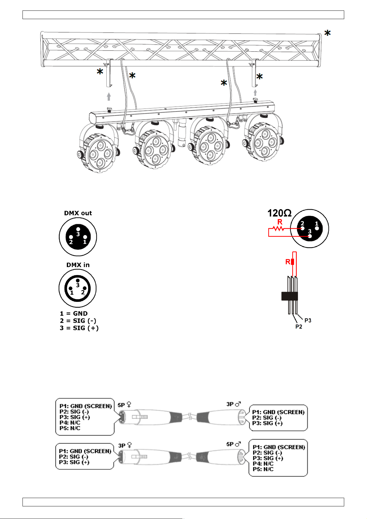
How to turn the controller line from 3-pins into 5-pins (plug and socket).
Controller line van 3-pin naar 5-pin aanpassen (stekker en contact).
Modifier la ligne du contrôleur de 3 broches en 5 broches (fiche et contact).
Modificar la línea del controlador de 3 polos y 5 polos (conector y contacto).
Die Controller-Linie von 3-Pin nach 5-Pin anzupassen (Stecker und Kontakt).
Zamiana zcza sterownika z 3 wtykami na zcze z 5 wtykami (wtyczka i gniazdo).
V. 02 – 01/06/2012 3 ©Velleman nv
Page 4
.
oIm
t
.
.
o
n
n
m
w
t
e
m
.
p
s
e
e
e
d
E
t
h
n
t
a
n
Q
d
u
a
o
s
a
s
t
o
a
a
r
a
e
f
A
d
S
d
n
t
r
c
l
g
a
e
e
y
s
y
n
e
c
c
g
p
o
n
m
d
y
m
i
h
V
t
o
.
h
a
w
c
r
p
h
d
r
i
c
W
a
n
d
R
N
t
c
t
o
e
h
o
m
u
a
e
s
g
f
e
v
e
v
r
e
o
s
f
t
D
a
g
r
s
e
d
b
u
n
i
t
b
d
p
m
p
o
w
t
c
n
n
c
c
r
u
n
l
c
.
c
u
DPLDJBA
6
1
Intr
T
all reside
portant e
Th
ank you for
If
he device
2
Safe
This
symbol on t
har
the enviro
shou
ld be taken
distri
butor or to
If in
doubt, co
choosing H
duction
ts of the
vironmen
as damage
y Instr
Be very c
electrosh
Always di
activities
Indoor u
uropean U
al informa
e device o
ment. Do n
o a speciali
local recy
tact your l
Power™! P
in transit,
ctions
reful durin
cks.
connect m
re perform
e only. Ke
USE
ion
ion about
the packag
ot dispose
zed compan
ling service
ocal waste
ease read t
don't install
the install
ins power
d. Handle t
p this devi
R MA
his produ
e indicates
f the unit (
y for recycli
Respect th
disposal a
e manual t
or use it an
tion: touchi
hen device
he power c
e away for
UAL
t
hat disposa
r batteries)
ng. This de
local envi
uthorities.
oroughly b
d contact y
ng live wire
not in use o
rd by the pl
rain, mois
l of the devi
as unsorte
ice should
onmental r
fore bringi
ur dealer.
can cause
r when serv
ug only.
ture, splash
ce after its l
municipal
e returned
les.
g this devi
life-threate
cing or mai
ing and drip
ifecycle cou
aste; it
o your
e into servi
ing
tenance
ping liquids
d
e.
•
This devic
qualified p
•
Make sure
•
Do not cri
necessary
•
Use an ap
•
Install the
substance
•
Respect a
3
Gen
Keep this
Caution:
Do not s
• epilep
• temp
• perm
There are
and/or sp
falls unde
erson carry
that the av
p the pow
ropriate sa
VDPLDJB
.
minimum di
ral Gui
device awa
device heat
are directl
tic seizure i
rarily loss o
nent (irrev
no user-ser
re parts.
protection
out the ele
ilable volta
r cord and
ety cable t
R6 at a mi
stance of 1
elines
from child
up during
at the lig
sensitive
f sight (flas
rsible) eye
viceable pa
lass I. It is
tric connect
e does not
rotect it ag
fix the dev
imal distan
between t
en and una
use.
ht source,
eople
blindness)
amage.
ts inside th
therefore e
ion.
exceed the
ainst dama
ce (e.g. VD
e of 0.5 m
he device’s
thorized us
s this may
device. Re
sential that
voltage sta
e. Have an
LSC7 or V
rom flamm
ight output
ers.
cause
er to an au
the device
ed in the sp
authorised
LSC8).
ble and ex
and any illu
horized dea
e earthed.
ecifications
ealer repla
losive obje
minated su
ler for servi
Have a
of this man
e it if
ts or
face.
e
al.
Re
fer to the V
•
Familiaris
unqualifie
device.
V.
02 – 01/06/2
lleman®
Keep this
Protect thi
yourself wi
people. An
012
ervice an
evice awa
s device fro
th the funct
y damage t
Quality
from dust
shocks a
ons of the
at may occ
arranty on
nd extrem
d abuse. A
evice befor
ur will most
4
the last pa
temperatu
oid brute fo
actually u
probably b
es of this
es.
rce when o
ing it. Do n
due to unp
anual.
erating the
t allow ope
rofessional
device.
ration by
se of the
©Vellema
nv
Page 5
VDPLDJBAR6
• All modifications of the device are forbidden for safety reasons. Damage caused by user modifications to
the device is not covered by the warranty.
• Only use the device for its intended purpose. All other uses may lead to short circuits, burns, electroshocks,
lamp explosion, crash, etc. Using the device in an unauthorised way will void the warranty.
• Damage caused by disregard of certain guidelines in this manual is not covered by the warranty and the
dealer will not accept responsibility for any ensuing defects or problems.
• A qualified technician should install and service this device.
• Do not switch the device on immediately after it has been exposed to changes in temperature. Protect the
device against damage by leaving it switched off until it has reached room temperature.
• This device is designed for professional use on stage, in discos, theatres, etc. The VDPLDJBAR6 should
only be used indoors with an alternating current of 230 VAC/50 Hz.
• Lighting effects are not designed for permanent operation: regular operation breaks will prolong their lives.
• Keep this manual for future reference.
4. Features
• ultra-light weight: special for DJ and mobile use
• movable spots, per spot there are 4 tri-colour LEDs for a smooth colour mixing
• preprogrammed modes, with presets for colours and RGB programs
• auto mode speed adjustable, and built-in microphone for sound activation
• easy control via included foot pedal, with black-out function.
5. Overview
Refer to the illustrations on pages 2 and 3 of this manual.
A connector for LED spot (4x) J DIP switch
B earth terminal K mounting points
C power socket + fuse L horizontal fixing knob
D tripod securing knob M vertical fixing knob (2 per spot)
E DMX input N LEDs (4 per spot)
F DMX output O program selection pedal
G microphone P sound control pedal
H microphone sensitivity control knob Q freeze pedal
I connector for footswitch R blackout pedal
6. Mounting instructions
6.1 Choosing a Mounting Location
The VDPLDJBAR6 batten has been designed for indoor environments at temperatures up to 40°C. For
proper operation, the unit must be operated with an unobstructed air convection to its metal housing.
Do not:
• Operate the batten in environments with an ambient temperature higher than 40°C and a relative humidity
• Operate the batten in a closed environment smaller than 10 m³ unless forced air convection is provided.
higher than 75%.
6.2 Secure Mounting
Risk of injury. Overhead mounting requires extensive experience: calculating workload limits,
determining the installation material to be used… Have the material and the device itself checked
regularly. Do not attempt to install the device yourself if you lack these qualifications as improper
installation may result in injuries.
The VDPLDJBAR6 batten is designed to be mounted either on a tripod (not incl.) or on a truss (not incl.) using
2 truss clamps (not incl.).
Tripod:
• Carefully follow the instructions that came with your tripod.
• Make sure that the diameter of the inserted tripod tube is not less than 25 mm as otherwise secure
mounting cannot be guaranteed.
V. 02 – 01/06/2012 5 ©Velleman nv
Page 6
VDPLDJBAR6
• Slide the VDPLDJBAR6 over the tripod and secure it tightly by turning the knob [D] clockwise.
Truss mounting:
• Have the batten installed by a qualified person, respecting EN 60598-2-17 and all other applicable norms.
• The carrying construction must be able to support 10 times the weight of the batten for 1 hour without
deforming.
• Remove both bolts [K] from the batten and replace them by 2 truss clamps (not incl.).
Note: ALWAYS mount the batten with two clamps!
• The installation must always be secured with a secondary attachment e.g. a safety cable.
• Never stand directly below the batten when it is being mounted, removed or serviced. Have a qualified
technician check the batten once a year and once before you bring it into service.
• Install the batten in a location with few passers-by that is inaccessible to unauthorised persons.
• Make sure there is no flammable material within a 0.5 m radius of the batten.
• The installation has to be approved by an expert before the device is taken into service.
4-way footswitch:
Connect the footswitch to the light fixture [I].
6.3 DMX-512 connection
Refer to the illustrations on page 3 of this manual.
• When applicable, connect an XLR cable to the female 3-pin XLR output of a controller (not incl.) and the
other side to the male 3-pin XLR input [E] of the VDPLDJBAR6. Multiple VDPLDJBAR6s can be linked
through serial linking. The linking cable should be a dual core, screened cable with XLR input and output
connectors.
• A DMX terminator is recommended for installations where the DMX cable has to run a long distance or is in
an electrically noisy environment (e.g. discos). The terminator prevents corruption of the digital control
signal by electrical noise. The DMX terminator is simply an XLR plug with a 120 resistor between pins 2
and 3, which is then plugged into the XLR output socket [F] of the last device in the chain.
6.4 Connection to the AC Power Supply
The AC socket providing power to the VDPLDJBAR6 batten must be properly and separately
earthed. Do not use any other AC cords than the one provided or any other AC cord not
authorized by the manufacturer.
• Have a qualified electrician carry out the electric connection.
• Connect the batten to the mains with the power plug [C]. Make sure the used mains circuit is protected by
a 30mA Residual Current Device (RCD). Do not connect it to a dimming pack.
• Replace a blown fuse only with an identical fuse (F2A/250V).
7. Operation
Refer to the illustrations on page 2 of this manual.
The VDPLDJBAR6 can operate in five modes: sound controlled, automatic mode, master/slave mode,
DMX controlled mode or foot switch mode.
Sound controlled mode
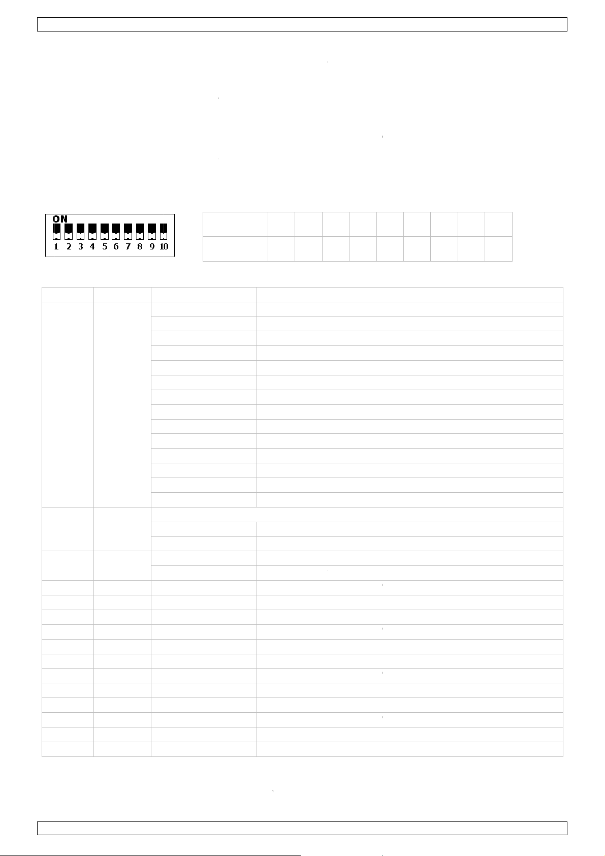
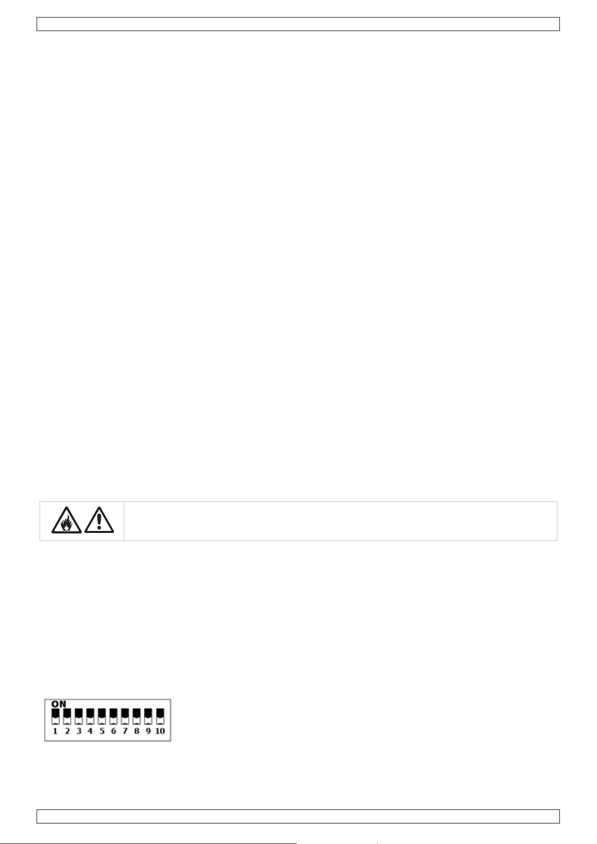
1. Set DIP switch 10 to the OFF-position to enable sound controlled mode.
2. Set the microphone [G] sensitivity with the sensitivity knob [H].
Automatic mode
1. Set DIP switch 9 to the ON-position and DIP switch 10 to the OFF-position to enable automatic mode.
2. Set the program speed with switches 1 to 3.
Master/slave mode
1. Connect multiple VDPLDJBAR6’s as described in §6.
2. Set the master VDPLDJBAR6 to sound controlled or automatic mode.
3. Set DIP switch 1 and 10 on the slaves to ON to enable slave mode.
V. 02 – 01/06/2012 6 ©Velleman nv
Page 7
M
hCHCHCHCH
H
H
H
HCHCHCHCH
H
HCH
oNo
w
o
e
d
n
,
I
h
tpro
adim
o
o
o
o
o
o
o
o
o
o
o
o
e
t
h
v
e
e
d
e
a
n
t
o
w
i
a
r
g
v
e
J
(
p
wval
e
v
0
2
4
6
8
0
2
4
6
8
0
2
4
5
h
0
5
0
5
5
5
5
5
5
5
5
5
5
5
5
5
V
e
t
e
u
e
s
H
e
n
t
u
C
m
s
e
e
e
e
V
R
r
c
a
a
o
e
e
e
w
o
o
o
o
R
r
e
o
t
e
e
r
1
a
a
%
0
0
%
0
0
%
0
0
%
0
0
r
e
C
f
(
e
e
e
e
f
n
2
n
c
f
e
D
X controll
•
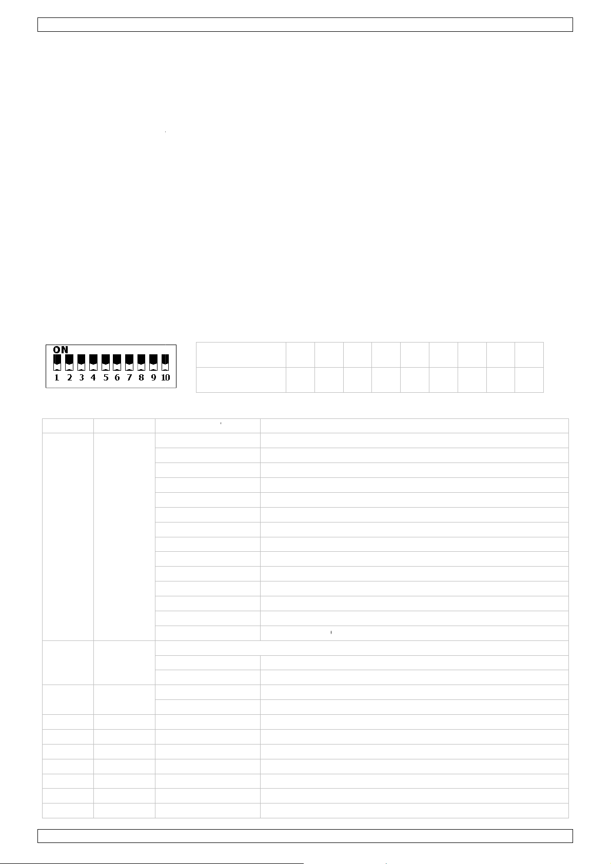
Set DIP s
•
All DMX-c
This digita
controller.
be set for
•
When all
channel. I
set individ
one chann
•
In case of
(CH1~15)
•
Use the D
ed mode
itch 10 to t
ntrolled de
l start addr
The same s
very devic
evices have
other wor
ual address
el will only
the 15-cha
the second
P switches
e ON-posit
ices need a
ss is the ch
tarting add
.
the same a
s: changin
s, each de
ffect the d
nel VDPLD
unit to 16
o set the a
on to enabl
digital star
nnel numb
ess can be
ddress, all t
the setting
ice will “list
vice in que
BAR6, you
1 + 15) (C
propriate D
DPLDJBA
DMX cont
address so
r from whi
sed for a w
he units will
s of one ch
n” to a sep
tion.
will have t
16~30), th
MX address.
6
olled mode.
that the co
h the devic
hole group
“listen” to
nnel will aff
rate chann
set the sta
third to 3
rect device
starts to “l
f devices o
he control s
ct all devic
l number.
t address o
(16 + 15)
responds to
isten” to th
an individu
ignal on on
s simultan
hanging th
the first u
(CH31~45),
the signals.
DMX
al address
particular
ously. If yo
settings o
it to 1
and so on.
an
u
•
Refer to t
C
annel Fu
1
2
3 str
4 sp
C
5 sp
C
6 sp
C
7 sp
C
8 sp
9 sp
10 sp
11 sp
12 sp
C
13 sp
C
14 sp
15 sp
ot controll
F
te: the foo
e table bel
nction
au
o
grams
m
ster
mer
obe
t1
t1
t1
t2
t2
t2
t3
t3
t3
t4
t4
t4
r
controller
w for an ov
DMX-512
000 ~ 0
010 ~ 0
030 ~ 0
050 ~ 0
070 ~ 0
090 ~ 1
110 ~ 1
130 ~ 1
150 ~ 1
170 ~ 1
190 ~ 2
210 ~ 2
230 ~ 2
250 ~ 2
function w
no
000 ~ 0
001 ~ 2
000 ~ 0
001 ~ 2
000 ~2
000 ~2
000 ~2
000 ~2
000 ~2
000 ~2
000 ~2
000 ~2
000 ~2
000 ~2
000 ~2
000 ~2
ill only wor
s
itch
ue
rview of th
alue Co
9 off
9 Pro
9 Pro
9 Pro
9 Pro
9 Pro
9 Pro
9 Pro
9 Pro
9 Pro
9 Pro
9 Pro
9 Au
5 so
en CH1 or
0 off
5 di
0 off
5 fla
5 red
5 gre
5 blu
5 red
5 gre
5 blu
5 red
5 gre
5 blu
5 red
5 gre
5 blu
k when the
1 2
1 2
control sig
trol Progr
gram 1
gram 2
gram 3
gram 4
gram 5
gram 6
gram 7
gram 8
gram 9
gram 10
gram 11
o mode, int
nd controll
H3 active
ming 0 ~ 1
h from slo
dimming fr
en dimming
dimming f
dimming fr
en dimming
dimming f
dimming fr
en dimming
dimming f
dimming fr
en dimming
dimming f
DPLDJBA
3 4
4 8
nals per ch
ams
rnal progr
d mode
0%
to fast
m 0 ~ 100
from 0 ~ 1
rom 0 ~ 10
m 0 ~ 100
from 0 ~ 1
rom 0 ~ 10
m 0 ~ 100
from 0 ~ 1
rom 0 ~ 10
m 0 ~ 100
from 0 ~ 1
rom 0 ~ 10
6 is set to
5 6
16 32
nnel.
ms
0%
%
0%
%
0%
%
0%
%
automatic o
7 8
64 128
r sound con
9
56
trolled mod
.
V.
02 – 01/06/2
012
7
©Vellema
nv
Page 8
VDPLDJBAR6
Unplug the power cord from the VDPLDJBAR6 and connect the foot controller to the foot controller jack [I].
Reconnect the power cord.
Foot controller functions:
Press to select a built-in program.
1x white
2x red
3x green
pedal 1
(O)
preset
4x blue
5x yellow
6x violet
7x cyan
8x colour change every second, continuous loop
9x colour fade every 3 seconds, continuous loop
pedal 2
(P)
pedal 3
(Q)
pedal 4
(R)
sound
controlled
freeze hold chasing programs (8 & 9)
black out
press to enter sound controlled mode
press pedal 1 to quit sound controlled mode
Press at any time to switch off all LEDs. Press again to return to previous setting.
Hold for strobe function.
8. Cleaning and Maintenance
• All screws should be tightened and free of corrosion.
• The housing, visible parts, mounting supports and the installation location (e.g. ceiling, suspension,
trussing) should not be deformed, modified or tampered with e.g. do not drill extra holes in mounting
supports, do not change the location of the connections.
• Moving mechanic parts must not show any signs of wear and tear.
• The electric power supply cables must not show any damage. Have a qualified technician maintain the
device.
• Disconnect the device from the mains prior to maintenance activities.
• Wipe the device regularly with a moist, lint-free cloth. Do not use alcohol or solvents.
• There are no user-serviceable parts.
• Contact your dealer for spare parts if necessary.
9. Technical Specifications
power supply 230VAC ~ 50Hz
fuse F2A/250V
power consumption 50W
LED 16 x 3W tri-colour LEDs
beam angle 15°
dimensions 950 x 45 x 230mm
total weight 6kg
Use this device with original accessories only. Velleman nv cannot be held responsible in the event
of damage or injury resulted from (incorrect) use of this device.
For more info concerning this product and the latest version of this manual, please visit our website
www.hqpower.eu.
The information in this manual is subject to change without prior notice.
© COPYRIGHT NOTICE
The copyright to this manual is owned by Velleman nv. All worldwide rights reserved.
No part of this manual may be copied, reproduced, translated or reduced to any electronic medium or otherwise
without the prior written consent of the copyright holder.
V. 02 – 01/06/2012 8 ©Velleman nv
Page 9
.
aBeHeDa
.
.
e
m
y
g
e
c
g
w
d
g
e
k
g
g
t
h
m
V
a
r
h
b
o
c
e
n
r
o
t
e
e
e
j
a
m
e
b
m
a
g
o
c
®
R
p
r
f
h
n
e
a
h
a
d
m
e
n
o
k
n
d
n
g
o
g
k
a
s
m
a
n
e
k
V
R
t
k
e
e
e
g
c
n
r
r
h
g
e
k
w
w
g
e
t
j
R
N
a
a
a
g
t
r
a
c
v
a
e
z
o
v
t
a
e
c
D
u
e
e
d
e
n
n
o
d
u
e
e
d
v
o
c
e
w
k
h
d
i
o
C
n
w
v
e
c
e
e
o
r
n
r
e
n
e
a
e
e
.
DPLDJBA
6
1
Inlei
A
n alle ing
langrijke
bt u vrage
nk u voor u
be
schadigd tij
2
Veili
ding
zetenen v
Dit s
weg
batt
tere
bren
n, contact
ilieu-info
mbool op
eworpen, d
rijen) niet
htkomen v
en. Respe
aankoop!
ens het tra
heidsi
Wees voo
elektrosh
Trek de s
u het niet
Gebruik h
vloeistoff
GEB
n de Euro
matie bet
et toestel o
it toestel sc
ij het gewo
or recyclag
teer de pla
er dan de
Lees deze
nsport, inst
structie
zichtig bij
cks te ver
ekker uit h
gebruikt.
t toestel e
n.
UIKE
ese Unie
effende di
de verpak
ade kan to
e huishoud
. U moet di
tselijke mili
plaatselijk
andleiding
lleer het da
s
e installatie
ijden.
t stopconta
kel binne
SHA
product
ing geeft a
brengen a
elijke afval;
t toestel na
uwetgevin
autoritei
rondig voo
n niet en ra
: raak geen
t (trek niet
shuis. Bes
DLEI
n dat, als h
n het milie
het moet bi
r uw verdel
.
en betreff
u het toest
dpleeg uw
kabels aan
aan de kab
herm tege
ING
et na zijn le
. Gooi dit t
j een gespe
er of naar e
nd de ver
l in gebrui
dealer.
ie onder st
l!) voordat
regen, voc
enscyclus
estel (en e
ialiseerd b
n lokaal re
ijdering.
neemt. W
room staan
u het toest
tigheid en
ordt
entuele
drijf
yclagepunt
rd het toest
om dodelijk
l reinigt en
pspattend
el
ls
•
Dit toestel
geschoold
De beschi
•
handleidin
De voedin
•
plaatsen.
Maak het
•
Installeer
•
stoffen.
•
Zorg voor
Houd buit
Let op: d
Kijk niet
• epilep
• tijdeli
• perm
te voorko
Er zijn ge
reserveon
valt onder
technicus
bare netsp
.
skabel ma
oestel vast
et toestel
een minimu
n het berei
it toestel w
rechtstree
sieaanvalle
ke blindhei
nente en o
en.
n door de
derdelen, c
eschermin
oet de ele
nning mag
niet besch
met een ge
p een mini
mafstand v
k van kinde
rdt zeer wa
s in de lic
bij gevoeli
(flitsblindh
herroepelij
ebruiker ve
ntacteer u
sklasse I,
trische aan
niet hoger z
digd zijn of
chikte veili
umafstand
n 1 m tuss
en en onbe
m tijdens h
tbron om
e personen
id)
e schade a
rvangbare o
dealer.
at wil zegg
sluiting ver
ijn dan de s
ingekort w
heidskabel
van 0,5 m
n de lichtui
oegden.
et gebruik.
n de ogen
nderdelen i
n dat het t
orgen.
panning in
rden. Laat
(bv. VDLSC
an ontvlam
gang van h
dit toestel.
estel geaar
e specificat
w dealer z
7 of VDLS
bare en exp
t toestel e
Voor onde
moet zijn.
es achteraa
nodig een
8).
losieve voo
het belicht
houd of
Een
n de
ieuwe kab
werpen of
oppervlak
l
3
Alge
Ra
adpleeg de
V.
02 – 01/06/2
ene ri
elleman
Bescherm
Bescherm
012
htlijne
service- e
tegen stof
tegen scho
n kwaliteit
n extreme
ken. Vermi
sgarantie
emperatur
d brute kra
9
chteraan d
n.
ht tijdens
ze handleid
e bediening
ing.
.
©Vellema
nv
Page 10
VDPLDJBAR6
• Leer eerst de functies van het toestel kennen voor u het gaat gebruiken. Ongeschoolde personen mogen dit
toestel niet gebruiken. Meestal is beschadiging het gevolg van onprofessioneel gebruik.
• Om veiligheidsredenen mag u geen wijzigingen aanbrengen. Schade door wijzigingen die de gebruiker heeft
aangebracht valt niet onder de garantie.
• Gebruik het toestel enkel waarvoor het gemaakt is. Andere toepassingen kunnen leiden tot kortsluitingen,
brandwonden, elektrische schokken, enz. Bij onoordeelkundig gebruik vervalt de garantie.
• De garantie geldt niet voor schade door het negeren van bepaalde richtlijnen in deze handleiding en uw
dealer zal de verantwoordelijkheid afwijzen voor defecten of problemen die hier rechtstreeks verband mee
houden.
• Laat dit toestel installeren en onderhouden door een geschoolde technicus.
• Om beschadiging te vermijden, zet u het toestel best niet aan onmiddellijk nadat het werd blootgesteld aan
temperatuurschommelingen. Wacht tot het toestel op kamertemperatuur gekomen is.
• Dit toestel is ontworpen voor professioneel gebruik op podia, in disco's, enz. U mag dit toestel enkel
binnenshuis gebruiken en aansluiten op een wisselspanning van 230 VAC/50 Hz.
• Lichteffecten zijn niet ontworpen voor continue werking: regelmatige onderbrekingen doen ze langer
meegaan.
• Bewaar deze handleiding voor verdere raadpleging.
4. Eigenschappen
• uiterst licht: speciaal voor dj's en mobiel gebruik
• richtbare spots, per spot zijn er 4 driekleurige LEDS voor vloeiende kleurovergangen
• voorgeprogrammeerde modi, met ingestelde kleurwaardes en RGB programma's
• snelheid automodus instelbaar, en ingebouwde microfoon voor geluidssturing
• eenvoudige bediening via meegeleverde voetpedaal, met 'black out' (alles uit) functie.
5. Omschrijving
Raadpleeg de afbeeldingen op pagina’s 2 en 3 van deze handleiding.
A aansluiting voor led spot (4x) J DIP- schakelaar
B aansluiting aarding K montagepunten
C aansluiting stroomkabel + zekering L horizontale positieknop
D beveiligingsknop statief M verticale positieknop (2 per spot)
E DMX ingang N leds (4 per spot)
F DMX uitgang O voetpedaal programmaselectie
G microfoon P voetpedaal muzieksturing
H gevoeligheidsregeling microfoon Q voetpedaal freeze
I aansluiting voor voetpedaal R black-out voetpedaal (alle leds uit)
6. Voorbereiding
6.1 Keuze van de montageplaats
De VDPLDJBAR6 werd ontworpen voor gebruik binnenshuis aan temperaturen lager dan 40°C.
Voorzie een aangepaste ventilatie en richt deze naar de metalen behuizing van de spots.
Het is niet aan te raden om:
• De spots te gebruiken in een omgeving met een omgevingstemperatuur hoger dan 40°C en een relatieve
• De spots te gebruiken in een ruimte kleiner dan 10 m³ tenzij er ventilatie is voorzien.
vochtigheid hoger dan 75%.
6.2 Montage
Gevaar voor verwondingen. Een degelijke praktijkervaring is vereist voor de plaatsing van dit
toestel. U moet de maximumbelasting van de draagconstructie kunnen berekenen, weten welk
constructiemateriaal u kunt gebruiken en u moet het gebruikte materiaal en het toestel af en toe laten
nakijken. Monteer het toestel niet zelf indien u er geen ervaring mee heeft. Een slechte montage kan
leiden tot verwondingen.
Monteer de VDPLDJBAR6 op een statief (niet meegelev.) of aan een draagstructuur (truss, niet meegelev.)
met behulp van twee trussklemmen (niet meegelev.).
V. 02 – 01/06/2012 10 ©Velleman nv
Page 11
VDPLDJBAR6
Statief:
• Volg nauwlettend de instructies die bij het statief werden meegeleverd.
• Zorg ervoor dat de diameter van de statiefbuis minstens 25 mm bedraagt om een goede bevestiging te
garanderen.
• Plaats de VDPLDJBAR6 op het statief en draai de beveiligingsknop [D] stevig aan (rechtsom).
Montage aan draagstructuur:
• Laat een geschoolde technicus dit toestel installeren conform EN 60598-2-17 en andere toepasselijke
normen.
• De constructie waaraan het toestel wordt bevestigd, moet gedurende 1 uur 10 x het gewicht van dit toestel
kunnen dragen zonder te vervormen.
• Verwijder beide bouten [K] uit de drager en vervang ze door twee trussklemmen (niet meegelev.).
Opmerking: monteer de VDPLDJBAR6 ALTIJD met twee klemmen.
• Maak het toestel ook vast met een veiligheidskabel.
• Sta nooit recht onder het toestel wanneer u het monteert, verwijdert of schoonveegt. Laat het toestel
controleren door een geschoolde technicus voor u het in gebruik neemt en laat het 1 x per jaar volledig
nakijken.
• Installeer dit toestel op een plaats waar niemand langs moet lopen, kan neerzitten of het toestel kan
aanraken.
• Verwijder alle brandbaar materiaal in een straal van 0,5 m rond het toestel.
• De installatie moet voor het eerste gebruik gekeurd worden door een expert.
4-wegs voetpedaal:
Sluit de voetpedaal aan op de draagbalk [I].
6.3 DMX512-aansluiting
Raadpleeg de afbeeldingen op pagina 3 van deze handleiding.
• Indien van toepassing, sluit een XLR-kabel aan de vrouwelijke 3-pin XLR-uitgang van een controller (niet
meegelev.) en de andere kant van de mannelijke 3-pin XLR-ingang [E] van de VDPLDJBAR6. U kunt
verscheidene VDPLDJBAR6’s aan elkaar koppelen met behulp van een seriële koppeling. Gebruik daarvoor
een 2-aderige afgeschermde kabel met XLR ingang- en uitgangsaansluitingen.
• Een DMX eindweerstand is aanbevolen als de DMX-kabel vrij lang is of wordt gebruikt in een omgeving met
veel elektrische ruis (bv. een discotheek). De eindweerstand voorkomt corruptie van het digitale
controlesignaal door elektrische ruis. De DMX eindweerstand is niets meer dan een XLR-stekker met een
weerstand van 120 van pin 2 naar 3. Deze XLR-stekker wordt dan aangesloten op de XLR-uitgang [F]
van het laatste toestel in de reeks.
6.4 Aansluiting op het voedingsnet
Koppel de spot aan een afzonderlijk geaard stopcontact. Gebruik geen andere voedingskabel
dan deze meegeleverd met de spot of een voedingskabel die niet door de fabrikant werd
goedgekeurd.
• Een geschoolde elektricien moet het toestel aansluiten.
• Sluit het toestel via de stekker [C] aan op het lichtnet. Zorg dat het gebruikte voedingscircuit beveiligd is
met een aardlekschakelaar van 30 mA. Sluit het niet aan op een dimmerpack.
• Vervang een opgeblazen zekering enkel door een identieke zekering (F2A/250V).
7. Gebruik
Raadpleeg de afbeeldingen op pagina 2 van deze handleiding.
De VDPLDJBAR6 beschikt over vijf aanstuurfuncties: muzieksturing, automatische sturing,
master/slavefunctie, DMX- of voetpedaalsturing.
Muzieksturing
1. Plaats DIP-schakelaar 10 in de OFF-stand om de muzieksturing in te schakelen.
2. Regel de gevoeligheid van de microfoon [G] met de instelknop [H].
V. 02 – 01/06/2012 11 ©Velleman nv
Page 12
u
a
M
aCHCH
HCH
HCHCH
H
HCH
e
-
k
o
e
e
e
-
-
g
D
o
u
w
u
w
s
n
t
o
m
o
o
o
o
o
o
o
o
e
P
f
o
k
s
d
d
5
m
e
s
t
h
d
m
b
k
n
e
e
D
v
-
r
w
a
5
5
5
5
5
5
5
V
P
e
h
n
p
g
e
n
k
6
r
c
m
o
o
o
o
o
o
o
o
o
o
o
t
u
H
m
s
o
o
o
o
o
R
r
3
e
s
d
n
(
21 2
e
d
0
v
v
v
z
r
n
r
k
v
4
8
m
%
0
0
%
0
0
%
m
e
t
e
n
t
t
6
3
r
e
t
a
t
p
6
1
n
n
d
e
n
5
A
tomatisch
1.
Plaats DIP
in te scha
Stel de pr
2.
ster/slav
M
1.
Koppel m
Schakel d
2.
Plaats DIP
3.
X-sturing
D
•
Plaats DIP
Alle DMX-
•
signalen.
de DMX-c
een nieuw
•
Wanneer
woorden:
Wanneer
woorden:
•
In het gev
moeten in
(CH31~45
•
Stel het st
sturing
schakelaar
elen.
grammasn
functie
erdere VD
muziek- o
schakelaar
schakelaar
estuurde t
it digitale s
ntroller. U
startadres i
een enkel
anneer u
verschillen
anneer u
al van de 1
tellen, van
), enz.
artadres in
9 in de ON-
lheid in me
LDJBAR6’s
automatisc
1 en 10 op
10 op ON o
estellen he
tartadres is
unt één en
ngeven.
tartadres i
e instelling
de adressen
e instelling
-kanaals V
het tweede
et behulp
tand en DI
DIP-schak
zoals omsc
e sturing i
e slaves o
de DMX-s
ben een di
het kanaaln
el startadr
stelt, zullen
n voor 1 ka
instelt, da
n van een
PLDJBAR
toestel op 1
an DIP-sch
DPLDJBA
-schakelaa
laars 1 tot
reven ond
op het ma
ON om de
turing in te
itaal starta
ummer van
s gebruiken
alle toestel
naal verand
luistert elk
anaal vera
, zult u het
6 (1 + 15)
akelaars 1 t
6
10 in de O
.
r §6.
tertoestel.
slavefunctie
schakelen.
res nodig,
waarop het
voor een g
len ‘luistere
ert, zullen a
toestel naa
dert, zal en
startadres
CH16~30),
t 9 (binair)
FF-stand o
in te schak
odat het jui
toestel ‘luis
oep toestell
’ naar hetz
lle toestelle
een ander
el het toes
an het eers
van het der
.
de automa
len.
ste toestel
ert’ naar h
en of u kun
lfde kanaal
er tegelijk
kanaal. Met
el op dat k
e toestel o
de op 31 (1
tische sturi
eageert op
t signaal va
per toestel
. Met ander
op reagere
andere
naal reager
1 (CH1~1
+ 15)
g
e
n
.
en.
)
•
Raadpleeg
k
naal fu
1
2
C
3 str
4 sp
C
5 sp
6 sp
7 sp
C
8 sp
C
9 sp
10 sp
de tabel hi
ctie
au
o
pr
grams
ma
ster
di
mer
boscoop
t1
t1
t1
t2
t2
t2
t3
ronder voo
DMX512-
000 ~ 0
010 ~ 0
030 ~ 0
050 ~ 0
070 ~ 0
090 ~ 1
110 ~ 1
130 ~ 1
150 ~ 1
170 ~ 1
190 ~ 2
210 ~ 2
230 ~ 2
250 ~ 2
et van toep
Ni
000 ~ 0
001 ~ 2
000 ~ 0
001 ~ 2
000 ~2
000 ~2
000 ~2
000 ~2
000 ~2
000 ~2
000 ~2
DIP
waa
rde
een overzi
aarde o
09 off
29 pr
49 pr
69 pr
89 pr
09 pr
29 pr
49 pr
69 pr
89 pr
09 pr
29 pr
49 au
55 m
00 off
55 di
00 off
55 fla
schakelaa
ssing als C
5 ro
5 gr
5 bla
5 ro
5 gr
5 bla
5 ro
1
ht van de s
schrijving
gramma 1
gramma 2
gramma 3
gramma 4
gramma 5
gramma 6
gramma 7
gramma 8
gramma 9
gramma 10
gramma 11
o mode, int
ziekgestuur
1 of CH3 g
men 0 ~ 1
h van traag
d dimmen
en dimmen
uw dimmen
d dimmen
en dimmen
uw dimmen
d dimmen
3
4
ignalen per
rne progra
e modus
eselecteerd
0%
naar snel
an 0 ~ 100
van 0 ~ 10
van 0 ~ 10
an 0 ~ 100
van 0 ~ 10
van 0 ~ 10
an 0 ~ 100
5
16
kanaal.
ma’s
zijn
%
%
%
%
7
2 64
8 9
28 256
V.
02 – 01/06/2
012
12
©Vellema
nv
Page 13

VDPLDJBAR6
kanaal functie DMX512-waarde omschrijving
CH11 spot3 000 ~255 groen dimmen van 0 ~ 100%
CH12 spot3 000 ~255 blauw dimmen van 0 ~ 100%
CH13 spot4 000 ~255 rood dimmen van 0 ~ 100%
CH14 spot4 000 ~255 groen dimmen van 0 ~ 100%
CH15 spot4 000 ~255 blauw dimmen van 0 ~ 100%
Voetpedaal
Opmerking: Het voetpedaal functioneert enkel indien de automatische of muzieksturing geselecteerd is.
Ontkoppel de voedingsstekker en koppel het voetpedaal aan de ingang [I]. Steek de voedingsstekker terug in
het stopcontact.
Functies:
Duwen om een ingebouwd programma te selecteren.
1x wit
2x rood
3x groen
pedaal 1
(O)
vooraf ingesteld
4x blauw
5x geel
6x violet
7x cyaan
8x kleurverandering om de seconde, doorlopende lus
9x kleurenovergang om de 3 seconden, doorlopende lus
pedaal 2
(P)
pedaal 3
(Q)
pedaal 4
(R)
muzieksturing
functie ‘freeze’ stopzetten van chaser programma’s (8 & 9)
functie
‘black out’
duwen om in muziekgestuurde modus te gaan
duwen op pedaal 1 om de muziekgestuurde modus te verlaten
Duwen om de leds uit te schakelen. Opnieuw duwen om terug te keren naar de
vorige instellingen. Ingedrukt houden voor stroboscoopeffect
8. Reiniging en onderhoud
• Alle gebruikte schroeven moeten goed zijn aangespannen en mogen geen sporen van roest vertonen.
• De behuizing, de lenzen, de montagebeugels en de montageplaats (bv. het plafond of het gebinte) mogen
niet vervormd zijn of aangepast worden (geen extra gaten in montagebeugels, aansluitingen niet
verplaatsen, enz.)
• Mechanisch bewegende delen mogen geen sporen van slijtage vertonen en mogen niet onregelmatig
bewegen.
• De voedingskabels mogen niet beschadigd zijn. Laat het toestel onderhouden door een geschoolde
technicus.
• Ontkoppel het toestel van het lichtnet voor u aan onderhoudswerkzaamheden begint.
• Maak het toestel geregeld schoon met een vochtige, niet pluizende doek. Gebruik geen alcohol of solvent.
• De gebruiker mag geen onderdelen vervangen.
• Bestel eventuele reserveonderdelen bij uw dealer.
9. Technische specificaties
voeding 230VAC ~ 50Hz
zekering F2A/250V
verbruik 50W
leds 16 x 3W driekleurige leds
stralingshoek 15°
afmetingen 950 x 45 x 230mm
gewicht 6kg
V. 02 – 01/06/2012 13 ©Velleman nv
Page 14

VDPLDJBAR6
Gebruik dit toestel enkel met originele accessoires. Velleman nv is niet aansprakelijk voor schade of
kwetsuren bij (verkeerd) gebruik van dit toestel.
Voor meer informatie over dit product en de laatste versie van deze handleiding, zie
www.hqpower.eu.
De informatie in deze handleiding kan te allen tijde worden gewijzigd zonder voorafgaande
kennisgeving.
© AUTEURSRECHT
Velleman nv heeft het auteursrecht voor deze handleiding. Alle wereldwijde rechten voorbehouden.
Het is niet toegestaan om deze handleiding of gedeelten ervan over te nemen, te kopiëren, te vertalen, te
bewerken en op te slaan op een elektronisch medium zonder voorafgaande schriftelijke toestemming van de
rechthebbende.
V. 02 – 01/06/2012 14 ©Velleman nv
Page 15

.
uDeEnNo
p
.
.
o
s
t
y
e
o
e
e
m
a
s
e
’
r
e
c
r
n
o
n
s
e
n
v
t
e
Ê
e
e
t
n
e
s
u
o
u
e
t
p
n
a
e
A
e
gé
d
r
n
p
x
s
a
t
’
t
n
t
e
m
n
m
e
o
p
a
e
u
m
V
C
a
e
v
s
s
d
e
v
n
.
I
e
s
r
a
i
e
é
é
p
R
M
e
e
t
u
c
t
n
p
u
j
s
t
p
m
e
5
u
n
c
s
I
p
n
é
c
e
o
e
o
o
u
j
a
e
m
7
o
a
x
s
r
t
c
s
v
t
8
a
p
m
a
e
s
e
r
e
s
d
t
q
u
m
a
f
n
s
o
c
DPLDJBA
6
1
Intr
A
x résident
s informa
cas de qu
us vous re
l’a
pareil. Si l’
2
Con
Ce s
pollu
parm
Renv
resp
duction
de l'Unio
ions envir
mbole sur l'
r l'environ
i les déchet
yer les équ
cter la régl
stions, co
ercions de
ppareil a é
ignes d
tre prud
mortels.
Débranch
l'appareil
Utiliser ce
projection
europée
nnementa
appareil ou
ement. Ne
municipau
ipements u
mentation l
tacter les
otre achat
é endomm
sécuri
nt lors de l
r l’appareil
; non pas le
appareil u
s d’eau.
NOTI
ne
les import
l'emballage
as jeter un
non sujets
agés à votr
ocale relati
autorités l
! Lire la pré
gé pendant
é
installation
s’il n’est pa
câble.
iquement
E D’E
ntes conc
indique que
appareil él
au tri sélec
fournisse
e à la prote
ocales pou
ente notice
le transpor
: toucher u
utilisé ou
à l'intérie
PLO
rnant ce
l’éliminatio
ctrique ou
if ; une dé
r ou à un s
tion de l’en
r éliminati
attentivem
, ne pas l’in
câble sous
our le nett
r. Protéger
roduit
d’un appa
lectronique
hèterie trai
rvice de re
vironnemen
n.
nt avant la
staller et co
tension peu
yer. Tirer la
de la pluie,
eil en fin d
(et des pile
era l’appar
yclage local
t.
mise en se
nsulter votr
t causer de
fiche pour
de l’humidi
vie peut
éventuelle
il en questi
. Il convient
vice de
revendeur
électrocho
ébrancher
é et des
)
n.
de
.
s
•
Cet appar
technicien
La tension
•
notice.
Le câble d
•
renouvele
Fixer l’app
•
Installer l
•
explosif.
Respecter
•
Garder ho
Attentio
Ne pas r
• de cri
• d’ave
• d’end
Il n’y a a
éventuell
il ressort à
qualifié doi
réseau ne
alimentatio
le câble d’
areil à l’aid
VDPLDJB
une distanc
rs de la por
: le boîtier
garder dir
e d’épilepsi
glement te
mmageme
cune pièce
s chez votr
la classe de
établir la c
eut pas dé
ne peut p
limentation
d’un câble
R6 à une d
minimum
ée des enfa
du spot cha
ctement
e chez les p
poraire (a
t permane
aintenable
revendeur
protection
nnexion él
asser la ten
s être repli
si nécessai
de sécurité
istance min
de 1 m entr
nts et des p
uffe pendan
ans la sou
rsonnes su
euglement
t et irréver
par l’utilisa
, ce qui im
ctrique.
sion mentio
sé ou endo
e.
déquat (p.
male de 0,
la sortie l
ersonnes n
t l’usage.
rce lumine
ettes
par éclair)
ible de l’œil
eur. Comm
lique que l’
nnée dans l
magé. De
x. VDLSC
m de tout
mière de l’
n autorisée
se afin d’é
.
ander des p
ppareil doit
s spécificat
ander à vo
ou VDLSC
bjet ou pro
ppareil et l
.
iter les ris
ièces de rec
être mis à l
ions à la fin
tre revende
).
duit inflam
surface illu
ues
hange
a terre. Un
de cette
r de
able ou
minée.
3
Dire
Se
référer à la
•
Se familia
non qualifi
V.
02 – 01/06/2
tives
garantie
Protéger c
Protéger c
iser avec le
ées d’opére
012
nérales
e service
ontre la po
ontre les ch
fonctionne
cet appare
t de qualit
ssière. Prot
ocs et le tra
ent de l’ap
il. La plupar
Vellema
ger contre
iter avec cir
areil avant
t des dégât
15
® en fin de
la chaleur e
onspection
de l’utiliser.
sont causé
notice.
trême.
pendant l’o
Ne pas per
par un us
ération.
ettre pas
ge non pro
ux personn
essionnel.
©Vellema
es
nv
Page 16

VDPLDJBAR6
• Toute modification est interdite pour des raisons de sécurité. Les dommages occasionnés par des
modifications par le client ne tombent pas sous la garantie.
• N’utiliser le spot qu’à sa fonction prévue. Tout autre usage peut causer des courts-circuits, des brûlures,
des électrochocs, etc. Un usage impropre annule d'office la garantie.
• La garantie ne s’applique pas aux dommages survenus en négligeant certaines directives de cette notice et
votre revendeur déclinera toute responsabilité pour les problèmes et les défauts qui en résultent.
• Confier l’installation et l’entretien à un personnel qualifié.
• Ne pas brancher l’appareil après exposition à des variations de température. Afin d’éviter des dommages,
attendre jusqu’à ce que l’appareil ait atteint la température ambiante avant de l’utiliser.
• Cet appareil a été développé pour usage professionnel dans des discothèques, des théâtres, etc. Employer
cet appareil à l’intérieur et le connecter à une source de courant CA de 230 VCA/50 Hz.
• Un effet lumineux n’est pas conçu pour une opération continue. Des pauses régulières prolongeront sa vie.
• Garder cette notice pour toute référence ultérieure.
4. Caractéristiques
• très léger : conçu spécialement pour DJ et usage mobile
• spots orientables, chaque spot est prévu de 4 LED tricolores pour une transition de couleurs aisée
• modes préprogrammés, avec des valeurs de couleurs préprogrammées et des programmes RGB
• vitesse du mode automatique ajustable , microphone incorporé pour le pilotage de la musique
• utilisation facile grâce au pédalier livré, avec fonction 'black out' (tout éteint).
5. Description
Voir illustrations page 2 et 3 de ce mode d’emploi.
A connexion pour spot à LED (4x) J interrupteur DIP
B connexion à la terre K points de montage
C connexion pour câble conducteur + fusible L bouton de positionnement horizontal
D bouton moleté du trépied M bouton de positionnement vertical (2 par spot)
E entrée DMX N LED (4 par spot)
F sortie DMX O pédalier sélection de programme
G microphone P pédalier pour le pilotage de son
H réglage de la sensibilité du microphone Q pédalier avec fonction ‘freeze’
I connexion pour pédalier R pédalier avec fonction 'black out'
6. Préparation
6.1 Choix d’un emplacement de montage
Les spots ont été conçus pour une utilisation dans un environnement à l’intérieur et avec des
températures jusqu’à 40°C. Prévoir une ventilation suffisante dirigée vers le boîtier métallique des
Ne pas :
• utiliser les spots lors d’une température ambiante supérieure à 40°C et un taux d’humidité supérieur à 75%
• utiliser les spots dans un environnement d’un volume inférieur à 10 m³ à moins de prévoir une ventilation
spots.
directe vers les spots.
6.2 Montage
Risque de blessures. L’installation de cet appareil exige une solide expérience pratique : le calcul de
la charge max. de la construction, les matériaux d’installation requis etc. De temps en temps, un
technicien qualifié doit vérifier la construction portante et l’appareil même. Ne pas essayer d’installer
cet appareil vous-même si vous n’avez pas les qualifications requises ; une installation incorrecte peut
entraîner des blessures.
Monter la herse VDPLDJBAR6 sur un trépied (pas livré) ou sur un ancrage (pas livré) à l’aide de deux colliers
d’ancrage (pas livrés).
Trépied :
• Suivre soigneusement les instructions fournies avec votre trépied.
• S’assurer que le tube du trépied a un diamètre d’au moins 25 mm pour garantir une fixation solide.
V. 02 – 01/06/2012 16 ©Velleman nv
Page 17

VDPLDJBAR6
• Monter la VDPLDJBAR6 sur le trépied et serrer le bouton moleté [D] fermement (vers la droite).
Montage sur armature :
• Un technicien qualifié doit installer l’appareil en respectant EN 60598-2-17 et toute autre norme applicable.
• La construction portante de l’appareil doit être capable de supporter 10 x le poids de l’appareil pendant une
heure, sans qu’une déformation de la construction en résulte.
• Enlever les deux écrous [K] de l’armature et remplacer-les par deux colliers d’ancrage (pas livrés).
Remarque : monter la VDPLDJBAR6 TOUJOURS avec deux colliers d’ancrage.
• Fixer les spots à l’aide d’un câble de sécurité (sécurité supplémentaire).
• Éviter de vous positionner en dessous de l’appareil pour l’enlever ou lors du montage ou du nettoyage. Un
technicien qualifié doit réviser l’appareil avant la mise en service. Organiser une révision minutieuse
annuelle.
• Installer l’appareil à un endroit où personne ne peut passer ou s’asseoir et où personne ne peut le toucher.
• Enlever tout matériau inflammable dans un rayon de 0,5 m autour de l’appareil.
• Un expert doit approuver l’installation avant qu’elle puisse être prise en service.
Pédalier 4-voies :
Connecter le pédalier à l’armature d’éclairage [I].
6.3 Connexion DMX512
Voir illustrations page 3 de ce mode d’emploi.
• Si nécessaire, connecter un câble à fiche XLR à la sortie XLR femelle à 3 broches de votre contrôleur (non
incl.) et l’autre fiche XLR mâle à 3 broches à l’entrée [E] de la VDPLDJBAR6. Il est possible de relier
plusieurs VDPLDJBAR6 à partir d’une connexion sérielle. Utiliser un câble de connexion blindé à
2 conducteurs avec des connecteurs d’entrée et de sortie XLR.
• Une résistance de terminaison DMX est à recommander si le câble DMX doit couvrir une grande distance ou
s’il est utilisé dans un environnement avec beaucoup de bruit électrique (p.ex. une discothèque). La
résistance de terminaison prévient la corruption du signal de contrôle numérique par le bruit électrique. La
résistance de terminaison DMX n’est rien d’autre qu’une fiche XLR avec une résistance de 120 de
broche 2 vers broche 3. Cette fiche XLR est connectée à la sortie XLR [F] du dernier appareil de la série.
6.4 Connexion au réseau
Veiller à ce que la prise de courant à laquelle les spots sont connectés soit séparément mise
à la terre. Ne pas utiliser un cordon d’alimentation autre que celui fourni avec les spots ou un
cordon autorisé par le fabricant.
• Un électricien qualifié doit établir la connexion électrique.
• Brancher l’appareil sur le réseau électrique par la fiche d’alimentation [C]. Veiller à ne brancher la
VDPLDJBAR6 que sur un circuit protégé par un disjoncteur différentiel de 30 mA. Ne pas le brancher sur
un bloc de puissance.
• Remplacer un fusible grillé seulement par un fusible identique (F2A/250V).
7. Emploi
Voir illustrations page 2 de ce mode d’emploi.
Le VDPLDJBAR6 intègre cinq modes de pilotage : pilotage par le son, pilotage automatique, mode
maître/esclave, pilotage DMX ou avec pédalier.
Pilotage par le son
1. Placer l’interrupteur DIP 10 en position OFF pour activer le mode de pilotage par le son.
2. Régler la sensibilité du microphone [G] avec le bouton de réglage [H].
Pilotage automatique
1. Placer l’interrupteur DIP 9 en position ON et l’interrupteur DIP 10 en position OFF pour activer le mode de
pilotage automatique.
2. Configurer la vitesse de programme avec les interrupteurs 1 à 3.
Mode maître/esclave
1. Interconnecter plusieurs VDPLDJBAR6 comme décrit sous §6.
2. Activer le mode de pilotage par le son ou automatique sur l’appareil-maître.
V. 02 – 01/06/2012 17 ©Velleman nv
Page 18

l
HCHCHCHCHCHCHCHCHCHCHCH
H
HCH
X
p
c
e
p
d
D
5
g
o
dmaî
o
t
t
t
t
t
t
t
t
t
t
t
t
I
I
t
g
e
u
o
d
0
N
u
s
e
r
a
c
a
x
è
r
M
0
0
0
0
0
1
1
1
1
1
2
2
2
2
e
0
2
0
2
2
2
2
2
2
2
2
2
2
2
2
2
V
e
d
e
a
q
a
e
n
P
e
f
o
o
o
o
o
o
o
o
o
o
o
o
o
c
f
f
a
a
a
a
a
a
a
a
a
a
a
a
R
s
C
e
u
a
e
u
1
2
2
0
1
t
e
u
r
e
u
r
e
u
r
e
u
r
e
d
s
p
g
o
a
p
a
t
1
0
0
1
0
0
1
0
0
1
0
0
t
n
e
3
r
é
s
n
A
1
n
s
m
3.
Placer l’int
Pi
otage DM
•
Placer l’int
•
Tous les a
appareils
numéro d
de départ
•
Dans le ca
Tous les a
adresses
ajustemen
•
Pour le V
16 (1 + 1
•
Sélectionn
errupteur D
errupteur D
pareils pilo
orrects réa
canal sur l
pour toute
s d’une seul
pareils ser
e départ in
t des réglag
PLDJBAR6
) (CH16~3
er l’adresse
P 1 et 10 s
P 10 en po
és par un s
issent sur l
quel l’appa
ne série d’
e adresse, t
nt donc infl
ividuelles,
es d’un can
à 15 canau
), du troisi
de départ à
r les appar
ition ON po
ignal DMX d
s signaux
eil écoute l
ppareils ou
ous les app
uencés lors
haque app
l n’influenc
, l’adresse
me 31 (16
l’aide des i
DPLDJBA
ils esclave
ur activer le
emandent u
e contrôle.
contrôleur
une adress
reils « éco
ue vous ch
reil « écout
que l'appa
de départ d
+ 15) (CH3
terrupteurs
6
en position
mode de pi
ne adresse
ette adres
DMX. Vous
de départ
teront » les
ngez les ré
ra » son pr
reil sur ce c
premier a
~45), etc.
DIP 1 à 9 (
ON pour ac
lotage DMX.
e départ D
e de dépar
avez le choi
ar appareil.
mêmes sig
lages d’un
pre canal.
nal.
pareil est 1
mode binair
tiver le mod
MX pour as
numérique
x entre une
aux, sur u
seul canal.
Par conséqu
(CH1~15),
e).
e esclave.
urer que le
indique le
seule adres
seul canal.
vec des
ent, un
du deuxiè
se
e
nal fon
ca
C
1
2
3 str
4 spo
5 spo
6 spo
7 spo
8 spo
9 spo
10 spo
11 spo
12 spo
C
13 spo
C
14 spo
15 spo
ction
pro
aut
gra
tre
boscope
rammes
matiques
uateur
1
1
1
2
2
2
3
3
3
4
4
4
inter
valeu
valeur D
000 ~
010 ~
030 ~
050 ~
070 ~
090 ~
110 ~
130 ~
150 ~
170 ~
190 ~
210 ~
230 ~
250 ~
e s’appliqu
000 ~
001 ~
000 ~
001 ~
000 ~
000 ~
000 ~
000 ~
000 ~
000 ~
000 ~
000 ~
000 ~
000 ~
000 ~
000 ~
upteur DI
r
X512 d
09 of
29 pr
49 pr
69 pr
89 pr
09 pr
29 pr
49 pr
69 pr
89 pr
09 pr
29 pr
49 m
55 m
pas si les
00 of
55 va
00 of
55 fla
55 gr
55 gr
55 gr
55 gr
55 gr
55 gr
55 gr
55 gr
55 gr
55 gr
55 gr
55 gr
1
1
scription
gramme 1
gramme 2
gramme 3
gramme 4
gramme 5
gramme 6
gramme 7
gramme 8
gramme 9
gramme 1
gramme 1
de automa
de pilotage
anaux CH1
riation de 0
sh de lent v
duateur ro
duateur ve
duateur bl
duateur ro
duateur ve
duateur bl
duateur ro
duateur ve
duateur bl
duateur ro
duateur ve
duateur bl
3
4
ique, progr
par le son
ou CH3 son
~ 100%
rs rapide
ge de 0 ~
t de 0 ~ 1
u de 0 ~ 1
ge de 0 ~
t de 0 ~ 1
u de 0 ~ 1
ge de 0 ~
t de 0 ~ 1
u de 0 ~ 1
ge de 0 ~
t de 0 ~ 1
u de 0 ~ 1
4 5
8 16
mmes inte
sélectionn
00%
0%
0%
00%
0%
0%
00%
0%
0%
00%
0%
0%
6 7
2 64
nes
s
8 9
28 256
V.
02 – 01/06/2
012
18
©Vellema
nv
Page 19

VDPLDJBAR6
Le pédalier
Remarque : Le pédalier fonctionne uniquement en modes de pilotage automatique et par le son.
Déconnecter le câble d’alimentation de la VDPLDJBAR6 et connecter le pédalier à l’entrée [I]. Réinsérer la
fiche d’alimentation dans la prise de courant.
Fonctions :
Appuyer pour sélectionner un programme intégré.
1x blanc
2x rouge
3x vert
pédalier 1
(O)
préprogrammé
4x bleu
5x jaune
6x violet
7x cyan
8x variation de couleur chaque seconde, en boucle fermée
9x transition de couleur toutes les 3 secondes, en boucle fermée
pédalier 2
(P)
pédalier 3
(Q)
pédalier 4
(R)
pilotage par le son
fonction ‘freeze’ arrêter programmes de poursuite (8 & 9)
fonction ‘black out’
appuyer pour entrer en mode pilotage par le son
appuyer sur pédalier 1 pour quitter le mode pilotage par le son
Appuyer n’importe quand pour éteindre toutes les LED. Appuyer de nouveau
pour revenir à la configuration précédente. Maintenir enfoncé pour effet
stroboscopique.
8. Nettoyage et entretien
• Serrer les écrous et les vis et vérifier qu’ils ne rouillent pas.
• Le boîtier, les lentilles, les supports de montage et la construction portante ne peuvent pas être déformés,
adaptés ou bricolés p.ex. pas de trous additionnels dans un support, ne pas déplacer les connexions etc.
• Les parties mécaniques mobiles ne peuvent pas être usées ou bouger de manière irrégulière.
• Les câbles d'alimentation ne peuvent pas être endommagés. Un technicien qualifié doit entretenir l’appareil.
• Débrancher l’appareil avant de le nettoyer.
• Essuyer l’appareil régulièrement avec un chiffon humide non pelucheux. Éviter l’usage d’alcool et de
solvants.
• Il n’y a aucune pièce maintenable par l’utilisateur.
• Commander des pièces de rechange éventuelles chez votre revendeur.
9. Spécifications techniques
alimentation 230VCA ~ 50Hz
consommation F2A/250V
fusible 50W
LED 16 LED tricolores de 3W
angle du faisceau 15°
dimensions 950 x 45 x 230mm
poids 6kg
N’employer cet appareil qu’avec des accessoires d’origine. SA Velleman ne sera aucunement
responsable de dommages ou lésions survenus à un usage (incorrect) de cet appareil. Pour plus
d’information concernant cet article et la dernière version de cette notice, visiter notre site web
www.hqpower.eu. Toutes les informations présentées dans cette notice peuvent être modifiées
sans notification préalable.
© DROITS D’AUTEUR
SA Velleman est l’ayant droit des droits d’auteur pour cette notice. Tous droits mondiaux réservés.
Toute reproduction, traduction, copie ou diffusion, intégrale ou partielle, du contenu de cette notice par quelque
procédé ou sur tout support électronique que se soit est interdite sans l’accord préalable écrit de l’ayant droit.
V. 02 – 01/06/2012 19 ©Velleman nv
Page 20

.
lImSi
.
.
o
a
e
c
a
a
h
r
a
c
e
a
n
m
e
a
e
p
n
U
o
r
s
e
a
g
o
t
a
c
d
a
e
o
e
e
o
n
e
n
o
d
A
p
o
p
e
u
L
n
g
s
é
e
e
o
g
r
n
i
n
e
a
d
g
m
d
u
t
a
d
u
V
L
m
a
h
e
n
e
t
u
e
a
n
n
o
e
l
r
ó
a
a
o
c
0
m
t
n
n
R
U
o
u
a
s
m
r
e
u
o
s
s
e
o
e
a
é
t
s
y
a
r
s
u
b
R
e
s
m
r
s
a
u
a
q
p
n
g
f
a
V
o
m
p
e
c
a
a
o
b
e
c
e
r
n
C
e
o
n
o
s
a
e
o
p
e
c
o
m
n
é
n
o
m
ó
e
s
n
a
o
e
c
o
1
Intr
A
os ciudad
portantes
tiene dud
¡G
racias por h
Si
el aparato
2
Inst
Este
el m
No ti
espe
Resp
ducció
nos de la
informaci
símbolo en
dio ambien
re este apa
ializada en
ete las leye
s, contact
ber compr
a sufrido al
uccione
M
nión Euro
nes sobre
este aparat
te.
ato (ni las
reciclaje. D
locales en
con las a
do el VDP
ún daño e
s de se
NUA
ea
el medio a
o el embal
ilas, si las
vuelva est
relación co
toridades
DJBAR6! L
el transpor
uridad
DPLDJBA
DEL
biente c
je indica q
ubiera) en l
aparato a
el medio a
locales pa
a atentam
e no lo inst
6
SUA
ncernient
e, si tira la
basura do
u distribuid
biente.
a residuos
nte las inst
le y pónga
IO
a este pr
muestras i
éstica; de
or o a la uni
.
ucciones d
e en conta
ducto
nservibles,
e ir a una
dad de reci
l manual an
to con su di
odrían dañ
mpresa
laje local.
tes de usarl
stribuidor.
r
.
•
Este apar
tierra. La
•
Asegúrese
•
No aplast
afilada. Si
Fije el apa
•
Instale el
•
Respete u
•
Cuidado d
conectad
Desconec
limpiarlo.
Utilice el
tipo de sa
Mantenga
¡Ojo! La
No mire
• un at
• cegue
• lesion
El usuario
distribuid
to pertenec
onexión elé
de que la t
el cable de
es necesari
rato con un
parato a u
a distancia
urante la in
a la red el
e siempre
Tire siempr
parato sól
lpicadura o
el aparato l
aja del apa
irectame
que epilépt
ra temporal
s permane
no habrá d
r si necesit
a la clase
ctrica debe
nsión de re
alimentació
, pida a su
cable de se
a distancia
de mín. 1
talación: p
ctrica.
l aparato si
del enchuf
en interio
oteo.
ejos del alc
ato se calie
te a la fue
co en perso
(ceguera p
tes e irrev
efectuar e
piezas de
e protecci
llevarse a c
d no sea m
n y protéjal
distribuidor
uridad ade
mínima de
entre la sa
ede sufrir
no va a usa
para desc
res. No exp
nce de per
ta durante
te lumino
nas sensibl
r destello)
rsibles del
mantenimi
ecambio.
n I. Por lo t
bo por un t
yor que la
contra po
reemplazar
uado (p.ej.
,5m de cua
lida de luz
na peligros
rlo durante
nectar el c
onga este e
onas no ca
su operació
a para evit
s
jo.
nto de nin
nto, es ese
cnico cuali
ensión indic
ibles daños
el cable de
VDLSC7 o
lquier objet
el área ilu
descarga
n largo pe
ble de red,
uipo a lluvi
acitadas y
.
ar
una pieza.
ncial que el
icado.
ada en las
causados p
limentació
DLSC8).
o product
inada.
léctrica al t
íodo de tie
nunca del p
a, humedad
iños.
ontacte co
aparato est
specificacio
r algún tip
.
inflamable
car un cabl
po o antes
ropio cable.
ni a ningún
su
puesto a
es.
de superfi
o explosivo.
de
ie
3
Nor
Vé
ase la Gara
•
Familiaríc
La mayorí
Por razon
•
causados
V.
02 – 01/06/2
as gen
ntía de ser
No expo
No agite
se con el fu
de los dañ
s de seguri
or modifica
012
rales
vicio y cali
ga este eq
el aparato.
ncionamien
s son caus
ad, las mo
ciones no a
ad Velle
ipo a polvo
Evite usar e
o del apara
dos por un
ificaciones
torizadas,
an ® al fin
. No expong
xcesiva fue
o. Sólo per
uso inadec
o autorizad
o están cu
20
l de este m
a este equi
za durante
onas cualifi
ado.
as del apar
iertos por l
anual del u
o a temper
l manejo y
adas pued
to están pr
garantía.
uario.
turas extre
la instalaci
n manejar
hibidas. Lo
as.
n.
ste aparat
daños
©Vellema
.
nv
Page 21

VDPLDJBAR6
• Utilice sólo el VDPLDJBAR6 para aplicaciones descritas en este manual a fin de evitar p.ej. cortocircuitos,
quemaduras, descargas eléctricas, etc. Un uso desautorizado puede causar daños y anula la garantía
completamente.
• Los daños causados por descuido de las instrucciones de seguridad de este manual invalidarán su garantía
y su distribuidor no será responsable de ningún daño u otros problemas resultantes.
• La instalación y el mantenimiento deben ser realizados por personal especializado.
• No conecte el aparato si ha estado expuesto a grandes cambios de temperatura. Espere hasta que el
aparato llegue a la temperatura ambiente.
• Este aparato ha sido diseñado para uso profesional en una discoteca, un teatro, etc. y es apto para un uso
sólo en interiores. Conéctelo a una fuente de corriente CA de 230VCA / 50Hz.
• No ha sido diseñado para un uso ininterrumpido. Introduzca frecuentemente una pausa para prolongar la
vida del aparato.
• Guarde este manual del usuario para cuando necesite consultarlo.
4. Características
• muy ligero: ideal para pinchadiscos y el uso móvil
• focos orientables, cada foco incluye 4 LEDs tricolores para una transición suave de colores
• modos preprogramados, los valores de los colores y los programas RGB están programados
• velocidad del modo automático programable y control por la música gracias al micrófono incorporado
• fácil de utilizar gracias al interruptor de pie (incl.), con función 'blackout' (desactivar todo).
5. Descripción
Véase las figuras en la página 2 de este manual del usuario.
A conexión para foco con LEDs (4x) J interruptor DIP
B conexión a tierra K puntos de montaje
C conexión para el cable de alimentación + fusible L botón de fijación horizontal
D botón de seguridad para el pie M botón de fijación vertical (2 por foco)
E entrada DMX N LEDs (4 por foco)
F salida DMX O interruptor de pie para seleccionar el programa
G micrófono P interruptor de pie para el control por la música
H botón de ajuste para la sensibilidad del micrófono Q interruptor de pie para la función « freeze »
I conexión para el interruptor de pie R interruptor de pie para la función « blackout »
(todos los LEDs están desactivados)
6. Preparación
6.1 Seleccionar un lugar de montaje
El foco ha sido diseñado para un uso en interiores y con temperaturas hasta 40°C. Prevea una
ventilación suficiente dirigida hacia la caja metálica del foco.
NO:
• Utilice el foco con una temperatura ambiente superior a 40°C y una humedad superior al 75%.
• Utilice el foco en un lugar inferior a 10 m³ salvo al prever una ventilación directa hacia el foco.
6.2 Montaje
Riesgo de lesiones. La instalación de este aparato exige una sólida experiencia práctica: el cálculo de
la carga máx. de la construcción, los materiales de instalación requeridos, etc. De vez en cuando, un
técnico cualificado debe controlar la construcción portante y el aparato mismo. No intente instalar este
aparato usted mismo si no tiene las cualificaciones requeridas; una instalación incorrecta puede causar
lesiones.
Fije el VDPLDJBAR6 con dos abrazaderas (no incl.) al pie (no incl.) o a la barra (truss, no incl.)
Pie:
• Siga cuidadosamente las instrucciones que acompañan al trípode.
• Asegúrese de que el diámetro del tubo del pie sea de min. 25mm para garantizar una fijación segura.
V. 02 – 01/06/2012 21 ©Velleman nv
Page 22

VDPLDJBAR6
• Fije el VDPLDJBAR6 al pie y atornille el botón de seguridad [D] firmemente (en el sentido de las agujas
del reloj).
Montar la barra:
• Respete la directiva EN 60598-2-17 y toda norma nacional antes de instalar el aparato. La instalación debe
ser realizada por un técnico especializado.
• El soporte donde irá el aparato, debe ser capaz de sostener 10 veces el peso de éste durante una hora, sin
que se produzca una deformación de dicho soporte.
• Quite los dos tornillos [K] de la barra y reemplácelos por dos abrazaderas (no incl.).
Observación: monte SIEMPRE el VDPLDJBAR6 con dos abrazaderas.
• Fije siempre el VDPLDJBAR6 con un cable de seguridad (seguridad adicional).
• Evite ponerse debajo del aparato durante el montaje, la limpieza, etc. Un técnico especializado debe revisar
el aparato antes de la puesta en marcha. Después, debe revisarlo una vez al año.
• Instale el aparato fuera del alcance de personas no autorizadas y en un lugar con poca gente.
• Quite todo material inflamable en un radio de 0.5m alrededor del aparato.
• Un experto debe probar la instalación antes de la puesta en marcha.
Interruptor de pie de 4 vías:
Conecte el interruptor de pie a la barra [I].
6.3 Conexión DMX512
Véase las figuras en la página 3 de este manual del usuario.
• Si fuera necesario, conecte un cable con conector XLR (no incl.) a la salida XLR hembra de 3 polos del
controlador y el otro conector XLR macho de 3 polos a la entrada [E] del VDPLDJBAR6. Es posible
conectar varios VDPLDJBAR6 en serie. Use un cable blindado de doble hilo conductor con conectores XLR
de entrada y de salida VDPLDJBAR6.
• Se recomienda una terminación si el cable DMX debe cubrir una gran distancia o si se usa en un medio
ambiente con mucho ruido eléctrico (ej. una discoteca). La terminación impide que el ruido eléctrico
corrompa la señal de control numérico. La terminación DMX no es más que un conector XLR con una
resistencia de 120 de polo 2 a polo 3. Este conector XLR está conectado a la salida XLR [F] del último
aparato de la serie.
6.4 Conexión a la rojo
Asegúrese de que el enchufe al que está conectado el foco esté puesto a tierra por separado.
Utilice sólo el cable de alimentación entregado con el foco o un cable autorizado por el
fabricante.
• Pregunte a un electricista cómo hacer la conexión eléctrica.
• Conecte el aparato a la rojo eléctrica con la conexión de alimentación [C]. Asegúrese de que sólo conecte el
VDPLDJBAR6 a un circuito protegido por un disyuntor de corriente residual (RCD) de 30mA. Normalmente,
no se conectan efectos luminosos a dimmer packs (reguladores).
• Reemplace un fusible fundido sólo por uno del mismo tipo (F2A/250V).
7. Uso
Véase las figuras en la página 2 de este manual del usuario.
El VDPLDJBAR6 incorpora cinco modos de control: control por la música, control automático, modo
maestro/esclavo, control DMX o modo interruptor de pie.
Control por la música
1. Ponga el interruptor DIP 10 en la posición OFF para activar el modo de control por la música.
2. Ajuste la sensibilidad del micrófono [G] con el botón de ajuste [H].
Control automático
1. Ponga el interruptor DIP 9 en la posición ON y el interruptor DIP 10 en la posición OFF.
2. Ajuste la velocidad del programa con el interruptor de 1 a 3.
Modo maestro/esclavo
1. Interconecte varios VDPLDJBAR6 (véase §6).
2. Active el modo de control por la música o el control automático en el aparato-maestro.
V. 02 – 01/06/2012 22 ©Velleman nv
Page 23

o
aCH
HCH
HCHCHCHCHCHCH
H
HCHCH
H
n
n
u
n
o
d
o
m
e
e
n
g
o
e
r
o
o
o
o
o
o
o
o
o
o
o
o
M
e
e
n
a
C
s
J
1
n
s
e
p
a
o
ñ
1
l
r
m
X
0
0
0
0
0
1
1
1
1
1
2
2
2
2
0
2
0
2
2
2
2
2
2
2
2
2
2
2
2
2
V
o
s
n
ó
n
a
t
P
e
e
f
o
o
o
o
o
o
o
o
o
o
o
o
o
3
f
f
u
f
u
u
u
u
u
u
u
u
u
u
u
R
e
r
r
ó
M
r
a
c
n
a
2
2
c
t
n
n
e
a
g
p
s
e
+
o
4
8
m
ú
X
i
r
c
o
3
s
o
e
z
o
e
z
o
e
z
o
e
u
e
d
a
e
~
1
0
0
0
0
0
0
0
0
0
0
0
n
t
c
e
3.
Ponga el i
C
ntrol DMX
•
Ponga el i
Si se usa
•
reaccione
aparato re
para toda
•
Con una s
sincroniza
de todos l
tanto, ca
•
En el caso
segundo a
•
Seleccion
terruptor D
terruptor D
na señal D
a las señal
accionará a
una serie d
la direcció
amente a l
s canales.
biar los aju
del VDPLD
parato 16 (
la direcció
IP 1 y 10 d
IP 10 en la
X, cada ap
s de contr
las señales
aparatos o
inicial para
misma se
on varias d
tes de un s
BAR6 de 1
+ 15) (CH
inicial con
los aparat
osición ON
rato tiene
l correctas.
DMX del co
una direcci
una serie d
al. Por lo ta
irecciones i
olo canal só
5 canales, l
6~30), del
os interrup
DPLDJBA
s esclavos
para activa
u propia di
Esta direcci
trolador D
n inicial po
e aparatos,
nto, cambia
iciales, cad
lo afecta al
dirección i
tercer apar
ores DIP de
6
n la posició
el modo d
ección inici
n inicial di
X. Es posibl
aparato.
todos los a
r los ajuste
aparato re
anal en cu
icial del pri
to 31 (16
1 a 9 (mod
ON para a
control DM
l DMX para
ital es el pr
e elegir ent
aratos reac
de un solo
accionará in
stión.
mer aparat
15) (CH31
binario).
ctivar el mo
X.
asegurar q
mer canal
e una sola
ionarán
canal afect
dependient
es 1 (CH1
~45), etc.
do esclavo.
e los apara
n el cual el
irección ini
a los ajust
mente. Por
15), del
os
ial
s
lo
Vé
ase la sigui
C
nal Fu
1
C
2
3 est
C
4 foc
5 foc
6 foc
7 foc
8 foc
9 foc
10 foc
C
11 foc
C
12 foc
13 foc
14 foc
C
15 foc
nte lista pa
ción
pro
ramas
aut
máticos
dim
mer
ma
stro
oboscopio
1
1
1
2
2
2
3
3
3
4
4
4
inte
valo
ra un resu
Valor DM
000 ~
010 ~
030 ~
050 ~
070 ~
090 ~
110 ~
130 ~
150 ~
170 ~
190 ~
210 ~
230 ~
250 ~
in función s
000 ~
001 ~
000 ~
001 ~
000 ~
000 ~
000 ~
000 ~
000 ~
000 ~
000 ~
000 ~
000 ~
000 ~
000 ~
000 ~
ruptor DI
r
en de las s
-512 D
09 of
29 Pr
49 Pr
69 Pr
89 Pr
09 Pr
29 Pr
49 Pr
69 Pr
89 Pr
09 Pr
29 Pr
49 m
55 m
i CH1 o CH
00 of
55 of
00 aj
55 of
55 de
55 aj
55 aj
55 aj
55 aj
55 aj
55 aj
55 aj
55 aj
55 aj
55 aj
55 aj
1
1
ñales para
scripción
grama 1
grama 2
grama 3
grama 4
grama 5
grama 6
grama 7
grama 8
grama 9
grama 10
grama 11
do automá
do controla
es activo
ste de la in
stello de le
ste de la in
ste de la in
ste de la in
ste de la in
ste de la in
ste de la in
ste de la in
ste de la in
ste de la in
ste de la in
ste de la in
3
4
ada canal.
ico, progra
do por la m
tensidad de
to a rápido
tensidad de
tensidad de
tensidad de
tensidad de
tensidad de
tensidad de
tensidad de
tensidad de
tensidad de
tensidad de
tensidad de
5
16
as interno
sica
luz 0 ~ 100
luz (color r
luz (color v
luz (color a
luz (color r
luz (color v
luz (color a
luz (color r
luz (color v
luz (color a
luz (color r
luz (color v
6 7
2 64
%
jo) 0 ~ 10
rde) 0 ~ 1
ul) 0 ~ 10
jo) 0 ~ 10
rde) 0 ~ 1
ul) 0 ~ 10
jo) 0 ~ 10
rde) 0 ~ 1
ul) 0 ~ 10
jo) 0 ~ 10
rde) 0 ~ 1
8 9
28 256
%
0%
%
%
0%
%
%
0%
%
%
0%
V.
02 – 01/06/2
012
23
©Vellema
nv
Page 24

VDPLDJBAR6
Interruptor de pie
Nota: el interruptor de pie funciona sólo en el modo de control automático y el modo de control por la música .
Desconecte el cable de alimentación del VDPLDJBAR6 y conecte el interruptor de pie a la entrada [I]. Vuelva
a conectar el aparato a la red eléctrica.
Funciones:
Pulse para seleccionar un programa incorporado.
1x blanco
2x rojo
3x verde
interruptor de
pie 1 (O)
ajustes
preprogramados
4x azul
5x amarillo
6x violeta
7x cian
8x cambio de color cada segundo, bucle infinito
9x transición de colores cada 3 segundos, bucle infinito
interruptor de
pie 2 (P)
interruptor de
pie 3 (Q)
interruptor de
pie 4 (R)
control por la
música
función
« freeze »
función
« black out»
pulse para entrar en el modo controlado por la música
pulse interruptor de pie 1 para salir del modo controlado por la música
Desactivar los programas « chase » (seguimiento) (8 & 9)
Pulse en cualquier momento para desactivar todos los LEDs. Vuelva a
pulsar para volver al ajuste anterior. Mantenga pulsado para la función
estroboscópica.
8. Limpieza y mantenimiento
• Apriete bien las tuercas y los tornillos y verifique que no hay señales de oxidación.
• No modifique la caja, los soportes y las ópticas p.ej. no taladre agujeros adicionales en un soporte o no
modifique las conexiones, etc.
• Las partes móviles no pueden mostrar ningún rastro de desgaste y deben estar bien equilibradas.
• No dañe los cables de alimentación. Contacte con un técnico especializado para instalar el aparato.
• Desconecte el aparato de toda fuente antes de limpiarlo.
• Limpie el aparato regularmente con un paño húmedo. Evite el uso de alcohol y de disolventes.
• El usuario no habrá de efectuar el mantenimiento de ninguna pieza.
• Contacte con su distribuidor si necesita piezas de recambio.
9. Especificaciones
alimentación 230VAC ~ 50Hz
fusible F2A/250V
consumo 50W
LEDs 16 LEDs tricolores de 3W
ángulo del haz 15°
dimensiones 950 x 45 x 230mm
gewicht 6kg
Utilice este aparato sólo con los accesorios originales. Velleman NV no será responsable de daños ni
lesiones causados por un uso (indebido) de este aparato. Para más información sobre este producto
y la versión más reciente de este manual del usuario, visite nuestra página www.hqpower.eu. Se
pueden modificar las especificaciones y el contenido de este manual sin previo aviso.
© DERECHOS DE AUTOR
Velleman NV dispone de los derechos de autor para este manual del usuario. Todos los derechos
mundiales reservados.
Está estrictamente prohibido reproducir, traducir, copiar, editar y guardar este manual del usuario o partes de
ello sin previo permiso escrito del derecho habiente.
V. 02 – 01/06/2012 24 ©Velleman nv
Page 25

.
nWiFa
rGe
.
.
e
ü
o
w
e
e
l
e
c
e
u
e
e
e
e
B
e
e
n
S
ge
a
E
m
u
e
t
r
e
e
S
e
S
h
a
e
A
,
B
s
n
A
t
R
e
D
e
b
u
e
r
c
e
D
r
h
t
e
e
S
r
l
u
e
t
n
a
e
g
r
e
a
ä
V
N
P
c
e
w
e
E
6
ä
r
n
ö
e
e
v
ä
L
n
h
c
g
S
n
b
R
N
g
g
c
e
b
h
e
f
d
n
a
n
o
r
a
e
n
e
S
U
g
e
n
i
i
c
a
e
e
ü
s
B
d
u
d
ä
s
e
w
D
e
r
u
s
B
s
o
G
m
s
e
o
b
e
m
a
e
n
n
g
g
ä
r
a
g
C
x
n
n
e
z
u
DPLDJBA
6
1
Einf
A
alle Einw
chtige Um
lls Zweifel
Wi
r bedanken
so
gfältig dur
rät nicht un
2
Sich
Diese
nach
verw
müss
Händ
Umw
hrung
hner der
eltinfor
s Symbol a
seinem Leb
ndeten Bat
n von eine
er oder ein
ltvorschrift
bestehen,
uns für den
h. Überprüf
d wenden S
rheitsh
Seien Sie
Spannung
Trennen
den Netzs
BE
uropäisch
ationen ü
f dem Prod
nszyklus d
erien) nicht
spezialisie
örtliches Re
n.
wenden Si
Kauf des V
n Sie, ob T
ie sich an I
inweise
während de
stehenden
ie das Gerä
tecker an d
IENU
n Union
er dieses
kt oder der
r Umwelt S
als unsorti
ten Firma z
ycling-Unt
sich für
PLDJBAR
ansportsch
ren Händle
r Installatio
Leitungen k
bei Nichtb
r Grifffläch
GSA
rodukt
Verpackun
haden zufü
rtes Hausm
ecks Recy
rnehmen re
ntsorgung
! Lesen Sie
den vorlieg
.
des Gerät
nnte zu le
nutzung un
an und zie
LEIT
zeigt an, d
en kann. E
üll; die Einh
ling entsor
tourniert w
srichtlinie
diese Bedie
en. Sollte d
s sehr vors
ensgefährli
d vor jeder
en Sie nie
NG
ass die Ent
ntsorgen Si
eit oder ver
t werden.
rden. Resp
an Ihre ö
nungsanleit
es der Fall
chtig: das
hen elektri
Reinigung v
n der Netzl
orgung dies
die Einheit
endeten B
iese Einheit
ktieren Sie
tliche Beh
ng vor Inb
ein, verwe
erühren vo
chen Schlä
m Netz. Fa
eitung.
es Produkte
(oder
tterien
muss an de
die örtliche
rde.
triebnahm
den Sie das
unter
en führen.
ssen Sie da
s
n
u
•
Der Aufba
sein. Der
Vergewiss
•
beschrieb
Achten Si
•
kann. Bei
Machen Si
•
Sorgen Si
•
Gegenstä
Beachten
•
Fläche.
Verwende
Feuchte.
Halten Si
Achtung:
Blicken
• epilep
• zeitlic
• perm
zu vermei
Es gibt ke
des Gerät
lektrische
rn Sie sich
n in dieser
darauf, da
eschädigu
das Gerät
für einen
den oder S
ie eine min
n Sie das G
Kinder und
Berühren
ie nicht di
tische Anfäl
e Blindheid
nente und
den.
ine zu wart
s entsprich
nschluss da
dass die a
edienungs
s die Netzl
gen soll ein
mit einem
bstand von
offen.
imale Entfe
rät nur im
Unbefugte
ie das Geh
ekt in die
e bei empfi
(Blitzblind
nwiderrufli
nden Teile.
der Schutz
rf nur von e
zuschließen
nleitung.
itung nicht
e Fachkraft
eeigneten
min. 0,5 m
nung von 1
Innenber
om Gerät
use währen
ichtquelle
dlichen Me
eid)
he Augensc
Bestellen Si
klasse I. Ge
iner Fachkr
de Netzspa
equetscht
das Kabel e
icherheitsk
zwischen d
m zwische
ich. Schütz
ern.
des Betrie
, um
schen
häden
e eventuell
mäß den Vo
ft durchgef
nung nicht
der durch
setzen.
bel fest (z.
m Gerät un
der Lichta
n Sie das
bs nicht, de
Ersatzteile
rschriften
hrt werden
höher ist al
charfe Kant
. VDLSC7
entflamm
sbeute und
erät vor Re
nn das Geh
bei Ihrem F
uss das Ge
.
die Netzsp
n beschädi
der VDLS
aren und e
irgendeiner
en und
use heizt a
achhändler.
ät geerdet
nnung
t werden
8).
plosiven
beleuchtete
.
n
3
All
Si
he Vellem
V.
02 – 01/06/2
meine
n® Servic
Schützen
012
ichtlini
- und Qu
Sie das Ger
n
litätsgara
t vor Stau
tie am End
. Schützen
25
dieser Be
ie das Ger
ienungsanl
t vor extre
itung.
en Temper
aturen.
©Vellema
nv
Page 26

VDPLDJBAR6
Vermeiden Sie Erschütterungen. Vermeiden Sie rohe Gewalt während der Installation und
Bedienung des Gerätes.
• Nehmen Sie das Gerät erst in Betrieb, nachdem Sie sich mit seinen Funktionen vertraut gemacht haben.
Lassen Sie das Gerät nicht von Personen bedienen, die sich nicht mit dem Gerät auskennen. Meist ist die
Beschädigung des Gerätes das Ergebnis von unfachmännischer Bedienung.
• Eigenmächtige Veränderungen sind aus Sicherheitsgründen verboten. Bei Schäden verursacht durch
eigenmächtige Änderungen erlischt der Garantieanspruch.
• Verwenden Sie das Gerät nur für Anwendungen beschrieben in dieser Bedienungsanleitung sonst kann dies
zu Schäden am Produkt führen und erlischt der Garantieanspruch. Jede andere Verwendung ist mit
Gefahren wie Kurzschluss, Brandwunden, elektrischem Schlag, usw. verbunden.
• Bei Schäden, die durch Nichtbeachtung der Bedienungsanleitung verursacht werden, erlischt der
Garantieanspruch. Für daraus resultierende Folgeschäden übernimmt der Hersteller keine Haftung.
• Lassen Sie dieses Gerät von einem Fachmann installieren und warten.
• Das Gerät bei Temperaturschwankungen nicht sofort einschalten. Schützen Sie das Gerät vor
Beschädigung, indem Sie es ausgeschaltet lassen bis es akklimatisiert ist (Zimmertemperatur erreicht hat).
• Dieses Gerät wurde für den professionellen Einsatz auf Bühnen, in Discotheken, Theatern, usw. entworfen
und eignet sich nur für die Anwendung im Innenbereich. Verwenden Sie das Gerät mit einer
Wechselspannung von 230VAC / 50Hz.
• Das Gerät eignet sich nicht für permanenten Betrieb: eine regelmäßige Pause verlängert die Lebensdauer.
• Bewahren Sie diese Bedienungsanleitung für künftige Einsichtnahme auf.
4. Eigenschaften
• sehr leicht: ideal für Discjockeys und den mobilen Einsatz
• schwenk- und neigbare Scheinwerfer, jeder Scheinwerfer hat 4 dreifarbige LEDs für fließende
Farbübergänge
• vorprogrammierte Modi, mit eingestellten Farbwerten und RGB-Programmen
• einstellbare Geschwindigkeit des automatischen Modus und Musiksteuerung über eingebautes Mikrofon
• einfache Bedienung über den mitgelieferten Füßschalter, mit 'Blackout'-Funktion (alles ausschalten)
5. Umschreibung
Siehe Abbildungen, Seite 2 dieser Bedienungsanleitung.
A Anschluss für LED-Scheinwerfer (4x) J DIP-Schalter
B Masse-Anschluss K Montagepunkte
C Anschluss Stromkabel + Sicherung L horizontale Einstellknopf
D Sicherheitsknopf Stativ M vertikale Einstellknopf (2 pro Scheinwerfer)
E DMX-Eingang N LEDs (4 pro Scheinwerfer)
F DMX-Ausgang O Fußschalter für die Programmauswahl
G Mikrofon P Fußschalter für die Musiksteuerung
H Einstellknopf für die Empfindlichkeit des Mikrofons Q Fußschalter für die Freeze-Funktion
I Anschluss für den Fußschalter R Fußschalter für die Blackout-Funktion (alle
LEDs ausgeschaltet)
6. Vorbereitung
6.1 Den Montageort auswählen
Der VDPLDJBAR6 wurde für die Anwendung im Innenbereich bei Temperaturen niedriger als 40°C
entworfen. Sorgen Sie für eine geeignete Ventilation und richten Sie diese auf das Metallgehäuse des
Verwenden Sie den Scheinwerfer nicht:
• in einer Umgebung mit einer Umgebungstemperatur höher als 40°C und eine relative Feuchte höher
• in einem Raum kleiner als 10 m³ wenn es keine Ventilation gibt.
V. 02 – 01/06/2012 26 ©Velleman nv
Scheinwerfers.
als 75%.
Page 27

VDPLDJBAR6
6.2 Montage
Gefahr vor Verletzungen. Für die Installation des Gerätes ist eine solide praktische Erfahrung
notwendig. Sie müssen die Höchstlast einer Tragkonstruktion berechnen können, wissen welches
Baumaterial Sie verwenden können und Sie müssen das verwendete Material und das Gerät ab und zu
kontrollieren lassen. Montieren Sie das Gerät nie selber wenn Sie keine Erfahrung damit haben. Eine
schlechte Montage kann zu Verletzungen führen.
Befestigen Sie den VDPLDJBAR6 am Stativ (nicht mitgeliefert) oder an der Traverse (Truss, nicht mitgeliefert)
über zwei Traversenhalter (nicht mitgeliefert).
Stativ:
• Befolgen Sie sorgfältig die dem Stativ beiliegenden Anweisungen.
• Der Durchmesser des Rohres muss mindestens 25mm sein, um eine sichere Befestigung zu gewährleisten.
• Befestigen Sie den VDPLDJBAR6 am Stativ und drehen Sie den Sicherheitsknopf [D] gut fest (im
Uhrzeigersinn).
Befestigung an der Traverse:
• Lassen Sie das Gerät von einem Fachmann und gemäß den EN 60598-2-17 und allen anderen zutreffenden
Normen installieren.
• Die Konstruktion muss während einer Stunde eine Punktlast von maximal 10 x dem Gewicht des Geräts
tragen können, ohne dass Verformung verursacht wird.
• Entfernen Sie beide Bolzen [K] aus der Traverse und ersetzen Sie diese durch zwei Traversenhalter (nicht
mitgeliefert).
Bemerkung: Montieren Sie den VDPLDJBAR6 IMMER mit zwei Traversenhaltern.
• Das Gerät muss immer mit einer zweiten Befestigung z.B. mit einem Sicherheitskabel gesichert werden.
• Stehen Sie während der Montage, Entfernung oder Wartung nie direkt unter dem Gerät. Lassen Sie das
Gerät jährlich und vor der Inbetriebnahme von einem Fachmann prüfen.
• Montieren Sie das Gerät an einem Ort, an dem es wenig Vorübergehende gibt und der unzugänglich ist für
Unbefugte.
• Achten Sie darauf, dass sich kein entflammbares Material in einem Umkreis von 50 cm befindet.
• Die Installation muss vor Inbetriebnahme von einem Experten genehmigt werden.
4-Wege-Fußschalter:
Verbinden Sie den Fußschalter mit der Traverse [I].
6.3 DMX512-Anschluss
Siehe Abbildungen, Seite 3 dieser Bedienungsanleitung.
• Wenn nötig, so verbinden Sie ein XLR-Kabel mit dem 3-Pin XLR-Ausgang der Steuerung (nicht mitgeliefert)
und die andere Seite mit dem 3-Pin XLR-Eingang [E] des VDPLDJBAR6. Sie können verschiedene
VDPLDJBAR6 in Serie schalten. Verwenden Sie ein zweipoliges abgeschirmtes Kabel mit XLR Ein- und
Ausgangsanschlüssen.
• Ein DMX-Abschlusswiderstand ist empfehlenswert für Installationen, bei denen das DMX-Kabel lang ist oder
in einer Umgebung mit vielem elektrischem Rauschen (z.B. Discos). Der Abschlusswiderstand verhindert
Störung des digitalen Steuersignals durch elektrisches Rauschen. Der DMX-Abschlusswiderstand ist nur eine
XLR-Buchse mit einem 120 Widerstand zwischen 2 und 3, die den XLR-Ausgang [F] des letzten Geräts in
der Kette angeschlossen wird.
6.4 Anschluss an das Netz
Verbinden Sie den Scheinwerfer mit einer separat geerdeten Steckdose. Verwenden Sie nur
das mit dem Scheinwerfer mitgelieferten Netzkabel oder ein Netzkabel, das vom Hersteller
genehmigt worden ist.
• Lassen Sie das Gerät von einem qualifizierten Elektriker anschließen.
• Schließen Sie das Gerät an das Hauptnetz [C] und nicht an einen Dimmer an. Beachten Sie, dass der
verwendete Kreis mit einem mit einem Fehlerstrom-Schutzschalter (RCD) von 30 mA geschützt ist.
• Ersetzen Sie eine durchgebrannte Sicherung nur durch eine des gleichen Typs (F2A/250V).
7. Anwendung
Siehe Abbildungen, Seite 2 dieser Bedienungsanleitung.
Das Gerät verfügt über fünf Ansteuerfunktionen: Musiksteuerung, automatische Steuerung, Master-
/Slave-Funktion, DMX-Steuerung oder Fußschalter-Modus.
V. 02 – 01/06/2012 27 ©Velleman nv
Page 28

u
u
a
M
a
HCHCH
u
e
e
e
e
e
v
S
e
u
e
g
k
n
n
e
a
t
e
n
e
h
n
o
g
s
m
o
e
d
e
w
n
e
k
e
e
u
s
e
e
n
e
V
s
F
s
e
A
m
v
N
u
a
w
n
R
C
e
-
2
t
V
u
[
h
e
u
X
t
n
ü
n
e
h
S
d
e
e
f
o
o
o
o
o
o
o
o
o
o
o
u
H
f
m
f
R
n
m
f
P
e
g
a
u
t
ä
e
g
e
t
i
9
r
g
r
r
3
1
n
a
e
1
r
t
d
f
.
e
n
1
.
e
c
c
h
r
n
d
d
d
ä
m
n
a
h
v
S
n
u
C
2
n
a
-
e
e
M
siksteuer
1.
Stellen Si
2.
Regeln Si
A
tomatisch
1.
Stellen Si
einzuschal
2.
Stellen Si
ster-/Sla
M
1.
Verbinden
2.
Schalten
Stellen Si
3.
X-Steuer
D
•
Stellen Si
Alle DMX-
•
reagieren
Steuerung
verwende
Wenn alle
•
empfange
zur gleich
anderen K
beeinfluss
Im Falle d
•
zweiten Ei
müssen.
Stellen Si
•
ng
DIP-Schalt
die Empfin
Steuerun
DIP-Schalt
ten.
die Gesch
e-Funktio
Sie mehrer
ie die Musi
DIP-Schalt
ng
DIP-Schalt
esteuerten
ann. Diese
empfängt
oder eine
Geräte dies
. Mit ander
n Zeit beei
nal Signal
.
s 7-Kanal
heit auf 16
die Startad
r 10 auf O
lichkeit de
g
r 9 auf ON
indigkeit d
VDPLDJB
- oder auto
r 1 der Sla
r 10 auf O
Geräte bra
digitale Sta
nd ausführt
eparate St
lbe Startad
n Worten,
flusst. Wen
empfange
DPLDJBA
(1 + 15) (
resse mit d
F um die M
Mikrofons
und DIP-Sc
s Programs
R6. Siehe
atische St
e-Geräte a
um de DM
chen eine d
rtadresse is
. Sie könne
rtadresse f
resse habe
enn Sie di
n Sie versc
. Wenn Sie
6, werden
H16~30),
n DIP-Scha
DPLDJBA
siksteueru
G] mit de
alter 10 au
mit den DI
§6.
uerung auf
f ON um di
-Steuerun
igitale Start
die Kanaln
dieselbe S
r jedes Ger
, werden si
Einstellun
iedene Adr
die Einstellu
ie die Star
er dritten E
ltern 1 bis
6
g einzusch
Einstellkno
OFF um di
-Schaltern
dem Maste
Slave-Fun
einzuschal
dresse, so
mmer, von
artadresse
t eingeben
auf einem
en von ein
ssen einstel
ngen änder
adresse des
nheit auf 3
ein (binär)
lten.
pf [H].
automatis
bis 3 ein.
gerät ein.
ktion einzus
en.
ass das ric
der das Ge
ür eine gan
spezifische
m Kanal än
len, wird je
, wird nur
ersten Ger
(16 + 15)
he Steueru
chalten.
tige Gerät
ät die Befe
ze Gruppe
Kanal das
ern, werde
es Gerät a
as besagte
tes auf 1 (
(CH31~45)
g
uf die Sign
le der DMX
on Geräten
teuersignal
alle Gerät
f einem
Gerät
H1~15), d
usw. einstel
le
r
len
•
Siehe nac
K
nal Fu
C
1
2
3 Str
folgende Li
ktion
aut
matische
Pro
ramme
ter-
Ma
Di
mer
boskop
DIP
Wer
te für eine
DMX-51
000 ~
010 ~
030 ~
050 ~
070 ~
090 ~
110 ~
130 ~
150 ~
170 ~
190 ~
210 ~
230 ~
250 ~
ohne Funk
000 ~
001 ~
000 ~
001 ~
Schalter
t
Übersicht d
-Wert B
009 of
029 Pr
049 Pr
069 Pr
089 Pr
109 Pr
129 Pr
149 Pr
169 Pr
189 Pr
209 Pr
229 Pr
249 Au
255 M
ion wenn C
000 Of
255 Di
000 Of
255 Bli
1 2
1 2
r Signale p
schreibun
gram 1
gram 2
gram 3
gram 4
gram 5
gram 6
gram 7
gram 8
gram 9
gram 10
gram 11
tomatische
sikgesteue
1 oder CH
men 0 ~
tzen von la
3 4
4 8
o Kanal.
Modus, int
ter Modus
aktiv ist
00%
gsam auf s
5 6
16 32
rne Progra
hnell
7 8
64 128
me
9
56
V.
02 – 01/06/2
012
28
©Vellema
nv
Page 29

VDPLDJBAR6
Kanal Funktion DMX-512-Wert Beschreibung
CH4 Scheinwerfer 1 000 ~255 Rot dimmen von 0 ~ 100%
CH5 Scheinwerfer 1 000 ~255 Grün dimmen von 0 ~ 100%
CH6 Scheinwerfer 1 000 ~255 Blau dimmen von 0 ~ 100%
CH7 Scheinwerfer 2 000 ~255 Rot dimmen von 0 ~ 100%
CH8 Scheinwerfer 2 000 ~255 Grün dimmen von 0 ~ 100%
CH9 Scheinwerfer 2 000 ~255 Blau dimmen von 0 ~ 100%
CH10 Scheinwerfer 3 000 ~255 Rot dimmen von 0 ~ 100%
CH11 Scheinwerfer 3 000 ~255 Grün dimmen von 0 ~ 100%
CH12 Scheinwerfer 3 000 ~255 Blau dimmen von 0 ~ 100%
CH13 Scheinwerfer 4 000 ~255 Rot dimmen von 0 ~ 100%
CH14 Scheinwerfer 4 000 ~255 Grün dimmen von 0 ~ 100%
CH15 Scheinwerfer 4 000 ~255 Blau dimmen von 0 ~ 100%
Fußschalter
Bemerkung: Der Fußschalter funktioniert nur wenn Sie den automatischen Modus oder Musiksteuerung
ausgewählt haben.
Trennen Sie den Netzstecker und verbinden Sie den Fußschalter mit dem Eingang [I]. Verbinden Sie das Gerät
wieder mit dem Netz.
Funktionen:
Drücken Sie, um ein eingebautes Programm auszuwählen.
1x Weiß
2x Rot
3x Grün
Fußschalter 1
(O)
vorprogrammi
erte
Einstellungen
4x Blau
5x Gelb
6x Violett
7x Cyan
8x Farbwechsel jede Sekunde, Endlosschleife
9x Farbübergang alle 3 Sekunden, Endlosschleife
Fußschalter 2
(P)
Fußschalter 3
(Q)
Fußschalter 4
(R)
musikgesteuer
ter Modus
FreezeFunktion
Black outFunktion
Drücken Sie, um in den musikgesteuerten Modus zu gelangen
Drücken Sie Fußschalter 1 um den musikgesteuerten Modus zu verlassen
Die Chase-Programme ausschalten (8 & 9)
Drücken Sie egal wann, um alle LEDs auszuschalten. Drücken Sie wieder, um
zur vorigen Einstellung zurückzukehren. Halten Sie gedrückt für die
Stroboskop-Funktion.
8. Reinigung und Wartung
• Alle verwendeten Schrauben müssen fest angespannt werden und dürfen keine Rostspuren zeigen.
• Das Gehäuse, die Linsen, die Montagebügel und der Montageort (z.B. Decke oder Gebinde) dürfen nicht
angepasst werden, z.B. bohren Sie keine zusätzlichen Löcher in Montagebügel, verändern Sie die
Anschlüsse nicht, usw.)
• Mechanische bewegende Teile dürfen keine Spuren von Verschleiß aufweisen.
• Sorgen Sie dafür, dass die Netzkabel nicht beschädigt sind. Lassen Sie das Gerät von einer Fachkraft
warten.
• Trennen Sie das Gerät vom Netz ehe Sie mit den Servicearbeiten anfangen.
• Verwenden Sie zur Reinigung ein feuchtes, fusselfreies Tuch. Verwenden Sie auf keinen Fall Alkohol oder
irgendwelche Lösungsmittel.
• Die Teile dürfen nicht eigenmächtig ersetzt werden.
• Bestellen Sie eventuelle Ersatzteile bei Ihrem Fachhändler.
V. 02 – 01/06/2012 29 ©Velleman nv
Page 30

VDPLDJBAR6
9. Technische Daten
Stromversorgung 230VAC ~ 50Hz
Sicherung F2A/250V
Stromverbrauch 50W
LEDs 16 dreifarbige LEDs von 3W
Abstrahlwinkel 15°
Abmessungen 950 x 45 x 230mm
Gewicht 6kg
Verwenden Sie dieses Gerät nur mit originellen Zubehörteilen. Velleman NV übernimmt keine
Haftung für Schaden oder Verletzungen bei (falscher) Anwendung dieses Gerätes. Für mehr
Informationen zu diesem Produkt und die neueste Version dieser Bedienungsanleitung, siehe
www.hqpower.eu. Alle Änderungen ohne vorherige Ankündigung vorbehalten.
© URHEBERRECHT
Velleman NV besitzt das Urheberrecht für diese Bedienungsanleitung. Alle weltweiten Rechte
vorbehalten.
Ohne vorherige schriftliche Genehmigung des Urhebers ist es nicht gestattet, diese Bedienungsanleitung ganz
oder in Teilen zu reproduzieren, zu kopieren, zu übersetzen, zu bearbeiten oder zu speichern.
V. 02 – 01/06/2012 30 ©Velleman nv
Page 31

.
aW od
z
uy
.
.
oins
ę
t
m
e
u
k
k
k
p
a
z
r
e
e
e
p
w
.
c
a
r
a
z
c
b
n
z
l
d
e
a
e
n
m
c
w
r
r
u
o
e
e
e
c
a
w
e
l
m
c
o
r
N
o
n
e
o
z
a
H
a
e
e
j
y
u
r
k
s
c
j
n
s
e
h
w
o
l
z
V
K
ż
w
z
w
m
z
n
ę
s
z
g
e
r
z
y
e
c
e
d
e
a
z
d
o
.
o
e
R
O
ó
m
y
ó
m
o
p
z
d
c
a
ó
y
c
b
k
e
w
t
u
t
c
o
u
w
o
m
y
s
e
n
i
y
ł
s
k
a
n
a
o
w
m
y
c
a
n
e
m
K
e
i
u
u
a
n
p
y
n
c
z
c
e
a
y
o
w
y
z
a
y
e
l
w
e
n
8
1
Wst
Ni
niejsza ins
W
żne infor
razie wąt
padów.
D
ikujemy z
si
z instrukcj
wa urzd
2
Inst
Nini
jszy symbol
prod
zwy
ych pojem
recy
recy
liwości na
wybór pro
enia oraz n
p
rukcja pr
acje doty
ktu moe
lingiem. Ur
lingiem. Na
obsugi. J
ukcje b
I
eznaczona
zące ochr
umieszczo
y szkodliw
ikach na od
dzenie m
ley przestr
eży skont
uktu firmy
li urzdzen
ley skont
zpiecz
STRU
jest dla u
ny środo
y na urzd
dla rodo
pady. W ty
na przeka
ega lokal
ktować si
QPower™!
ie zostao u
ktowa si
ństwa
DPLDJBA
CJA
ytkownik
iska
eniu bd o
iska. Nie u
celu nale
a dystrybu
ych przepis
z lokalny
Przed rozp
zkodzone
e sprzedaw
6
BSŁU
w w kraja
pakowaniu
ieszcza z
skontakto
torowi lub l
w dotyczc
i władza
czciem u
odczas tran
c.
GI
h Unii Eur
znacza, e
ytych urz
a si z fir
kalnej firmi
ych ochron
i zajmują
tkowania n
portu, nie
pejskiej
yrzucenie
dze (bd
zajmuj
e zajmujc
rodowisk
ymi się ut
ley dokad
aley mont
uytego
baterii) w
si
j si
.
lizacją
nie zapozna
wa ani
•
Urzdzeni
elektryczn
•
Naley up
Nie zagina
•
powinien
Do monta
•
Zainstalo
•
substancji
Naley za
•
podwietl
Podczas i
napicie
Kiedy urz
konserwa
trzyma
Wyłączni
wilgoci,
Chroni u
Uwaga:
Nie kier
• atak
• przej
• trwa
W urzdz
uzyskania
sprzedaw
podlega kl
powinien
wni si,
kabla zasi
rzeprowadz
u urzdzeni
a VDPLDJ
howa mini
n powierz
stalacji nal
moe prow
dzenie nie
yjne nale
ycznie za
e do użytk
ozpryskami
zdzenie p
rzdzenie n
wać wzro
pilepsji u o
ciow utrat
(nieodwra
niu nie zna
czci serw
.
sie ochron
ykonywa
napicie ni
ajcego i c
a autoryzo
a naley st
BAR6 w od
aln odleg
hni.
y zachowa
adzi do za
est uywan
odczy u
wtyczk.
wewnątr
i ciekajc
zed dziemi
agrzewa si
u bezpośr
ób podatny
wzroku (l
alne) uszko
duj si cz
isowych i/lu
oci I, dlat
pecjalista.
przekracz
roni go pr
any sprze
sowa odp
egoci min
o o wart
szczególn
raajcego
lub gdy pr
zdzenie o
pomiesz
mi cieczami
i nieupowa
podczas pr
dnio na źr
h
pota olnie
zenie oczu
ci, które w
b zamienny
go te niez
wartoci o
ed uszkodz
awca.
wiedni prze
0,5 m od a
ci 1 m mi
ostrono
yciu pora
eprowadza
zasilania si
zeń. Chron
.
nionymi u
cy.
dło świat
niowa)
magaj ob
h naley s
dne jest z
relonej w
niem. W ra
ód zabezpi
wopalnych
dzy strumie
: dotknici
nia prde
e s prace
eciowego.
urzdzeni
tkownikam
a, gdy mo
ugi przez
ontaktowa
pewnienie
specyfikacj
zie koniecz
eczajcy (n
i wybuchow
iem wietl
przewodó
elektryczn
serwisowe l
abel zasilaj
przed des
.
e to wywo
ytkownika
si z autor
ziemienia.
ch niniejsz
oci, wymia
. VDLSC7
ch obiektó
ym urzdz
pod
m.
ub
cy naley
czem,
:
. W celu
zowanym
Poczenia
j instrukcji.
n kabla
ub VDLSC
lub
nia, a kad
).
3
Info
Pr
sz zapozn
trukcji.
V.
02 – 01/06/2
macje
si z info
Chroni u
012
ólne
rmacjami w
zdzenie pr
czci Vell
ed kurzem
man® Usł
i wysokimi
31
gi i gwar
emperatura
ncja jakoś
mi.
i na kocu
niniejszej
©Vellema
nv
Page 32

VDPLDJBAR6
Chroni urzdzenie przed wstrzsami i uytkowa wycznie zgodnie z przeznaczeniem. Podczas
obsugi urzdzenia unika uywania siy.
• Przed rozpoczciem pracy z urzdzeniem naley zapozna si z jego funkcjami. Zabrania si uytkowania
urzdzenia przez niewykwalifikowane osoby. Wszelkie moliwe uszkodzenia s zazwyczaj spowodowane
nieprofesjonaln obsug urzdzenia.
• Wprowadzanie zmian w urzdzeniu jest zabronione ze wzgldów bezpieczestwa. Naley pamita, e
uszkodzenia spowodowane przez zmiany wprowadzone przez uytkownika nie s objte gwarancj.
• Urzdzenia naley uywa jedynie zgodnie z przeznaczeniem. Jakiekolwiek uytkowanie niezgodnie z
przeznaczeniem moe prowadzi do zwarcia, poparze, poraenia prdem, wybuchu lampy, wypadku itd. i
spowoduje uniewanienie gwarancji.
• Gwarancja nie obejmuje uszkodze powstaych w wyniku nieprzestrzegania niniejszej instrukcji, a
sprzedawca nie ponosi odpowiedzialnoci za wynike uszkodzenia lub problemy.
• Urzdzenie powinien instalowa i serwisowa wykwalifikowany technik.
• Nie wcza urzdzenia bezporednio po wystpieniu zmiany temperatury. Chroni urzdzenie przed
uszkodzeniem wyczajc je dopóki nie osignie temperatury pokojowej.
• Urzdzenie jest przeznaczone do profesjonalnego zastosowania wewntrz pomieszcze na scenach, w
dyskotekach, teatrach itp., przy zasilaniu prdem przemiennym 230 VAC/ 50 Hz.
• Efekty wietlne nie s przystosowane do cigej pracy: regularne przerwy w pracy wydu ywotno
urzdzenia.
• Niniejsz instrukcj naley zachowa na przyszo.
4. Właściwości
• niezwykle niska masa: urzdzenie przenone, zaprojektowane specjalnie dla DJ-ów
• ruchome reflektory, kady reflektor zosta wyposaony w 4 trójkolorowe diody LED, zapewniajce doskonae
efekty wietlne
• wstpnie zaprogramowane tryby pracy z ustawieniami kolorów i programów RGB
• automatyczny tryb pracy z ustawieniami szybkoci oraz wbudowany mikrofon do aktywacji dwikiem
• atwe sterowanie dziki przecznikowi podogowemu, funkcja wygaszenia
5. Opis
Patrz rysunki na stronie 2 i 3 niniejszej instrukcji.
A zcze do reflektorów LED (4x) J segmentowy przecznik dwustanowy
B zacisk uziomowy K ruby montaowe
C gniazdko sieciowe + bezpiecznik L poziome pokrto nastawcze
D pokrto zabezpieczajce statyw M pionowe pokrto nastawcze (2 na reflektor)
E wejcie DMX N diody LED (4 na reflektor)
F wyjcie DMX O przecznik podogowy do wyboru programów
G mikrofon P przecznik podogowy do regulacji dwikiem
H pokrto do regulacji czuoci mikrofonu Q przecznik podogowy do funkcji zatrzymania
I gniazdko przecznika podogowego R przecznik podogowy do funkcji zaciemniania
6. Instrukcje montażu
6.1 Wybór miejsca montażu
Rampa sceniczna VDPLDJBAR6 zostaa zaprojektowana z myl o zastosowaniach wewntrznych, w
temperaturach nieprzekraczajcych 40°C. W celu zapewnienia bezawaryjnej pracy podczas obsugi
Nie należy:
• uywa rampy w miejscach o temperaturze otoczenia przekraczajcej 40°C i o wilgotnoci wzgldnej
• uywa rampy w zamknitych pomieszczeniach o powierzchni poniej 10m
V. 02 – 01/06/2012 32 ©Velleman nv
naley zapewni niezakócony dostp powietrza do metalowej obudowy urzdzenia.
ponad 75%.
3
, o ile nie zapewniono
wymuszonego obiegu powietrza.
Page 33

VDPLDJBAR6
6.2 Bezpieczny montaż
Ryzyko obrażeń ciała. Monta nadziemny wymaga duego dowiadczenia: obliczanie limitów
obcienia, wybór materiaów montaowych ... Urzdzenie oraz materiay naley regularnie
kontrolowa. Bez wymaganego dowiadczenia nie naley próbowa samodzielnie instalowa
urzdzenia, gdy moe to prowadzi do obrae ciaa.
Rampa VDPLDJBAR6 zostaa zaprojektowana z myl o montau na statywie (nie zaczono) lub belce
kratowej (nie zaczono) przy pomocy dwóch zacisków (nie zaczono).
Statyw:
• Naley dokadnie przestrzega instrukcji obsugi statywu.
• Upewni si, e rednica woonej rurki statywu jest nie mniejsza ni 25 mm; w przeciwnym wypadku
bezpieczny monta nie moe by zapewniony.
• Przymocowa urzdzenie do statywu i zabezpieczy je mocno dokrcajc pokrto [D] w kierunku
przeciwnym do ruchu wskazówek zegara.
Montaż na belce kratowej:
• Instalacj rampy powinna przeprowadzi wykwalifikowana osoba, zgodnie z norm EN 60598-2-17 i innymi
odnonymi normami.
• Konstrukcja nona musi utrzyma przez godzin bez odksztacania obci
enie 10 razy wiksze ni masa
rampy.
• Wyj obie ruby [K] z rampy i zastpi je 2 zaciskami belki kratowej (nie zaczone).
Uwaga: ZAWSZE naley mocowa ramp z zastosowaniem 2 zacisków!
• Instalacja musi by zawsze zabezpieczona dodatkowym elementem, np. przewodem bezpieczestwa.
• Podczas montau, zdejmowania lub serwisowania nigdy nie stawa bezporednio pod ramp. Raz do roku
oraz przed rozpoczciem uytkowania ramp naley podda kontroli przeprowadzanej przez
wykwalifikowanego technika.
• Ramp naley zamontowa w mao uczszczanym miejscu oraz w taki sposób, aby bya niedostpna dla
nieupowanionych uytkowników.
• Naley upewni si, e w promieniu 0,5 m od urzdzenia nie znajduje si materia
atwopalny.
• Przed rozpoczciem uytkowania urzdzenia instalacja musi zosta zatwierdzona przez eksperta.
4-drożny przełącznik podłogowy:
Podczy przecznik podogowy do oprawy owietleniowej [I].
6.3 Złącze DMX-512
Patrz rysunek na stronie 3 niniejszej instrukcji.
• O ile dotyczy, podczy przewód XLR do wyjcia eskiego XLR z trzema wtykami sterownika (nie
zaczono), a drugi koniec kabla do wejcia XLR z trzema wtykami [E] urzdzenia VDPLDJBAR6.
Urzdzenia VDPLDJBAR6 mog by poczone ze sob za pomoc cza szeregowego. Jako cza naley
uywa kabla dwurdzeniowego ekranowanego z wejciem XLR i zczami wyjciowymi.
• Do instalacji wymagaj
cych zastosowania przewodu DMX na dugich odcinkach lub instalacji w miejscach, w
których wystpuj szumy elektryczne (np. w dyskotekach), zaleca si uywanie terminatora DMX.
Terminator zapobiega przekamaniu cyfrowego sygnau sterujcego wywoanemu szumem elektrycznym.
Terminator DMX to wtyczka XLR z opornikiem 120 zainstalowanym midzy wtykiem 2 i 3, wkadana do
gniazda wyjciowego XLR [F] ostatniego urzdzenia w szeregu.
6.4 Podłączenie do źródła zasilania prądem przemiennym (AC)
Gniazdo AC zapewniajce zasilanie rampy VDPLDJBAR6 musi by odpowiednio i oddzielnie
uziemione. Nie uywa przewodu AC innego ni doczony ani adnego innego przewodu AC,
który nie jest zatwierdzony przez producenta.
• Poczenia przewodów elektrycznych powinny by wykonane przez wykwalifikowanego elektryka.
• Podczy wtyczk zasilajc rampy [C] do zasilania sieciowego. Naley upewni si, e stosowany obwód
zasilajcy jest zabezpieczony wycznikiem rónicowoprdowym (RCD) 30mA. Nie podcza urzdzenia do
dimmera.
• Stopiony bezpiecznik naley zastpi wycznie identycznym bezpiecznikiem (F1A/250V).
7. Obsługa
Patrz rysunek na stronie 2 niniejszej instrukcji.
Rampa VDPLDJBAR6 moe dziaa w piciu trybach: sterowania dźwiękiem, automatycznym,
uprzywilejowanym / zależnym, DMX oraz podłogowym.
V. 02 – 01/06/2012 33 ©Velleman nv
Page 34

y
y
y
y
a
H
a
o
w
t
o
w
r
i
a
p
c
o
O
o
e
y
a
y
d
d
5
r
k
k
m
u
n
g
/
A
a
a
M
o
s
z
z
a
y
G
y
o
a
y
n
w
y
o
d
y
y
y
X
z
r
D
~
~
~
~
~
~
~
~
~
~
~
~
~
~
V
w
c
e
o
z
n
y
D
r
X
d
m
a
z
z
o
A
1
m
e
w
r
r
r
r
r
r
r
r
r
r
r
Tr
Tr
R
t
o
p
w
e
b
z
a
s
e
w
m
o
e
3
p
n
e
t
n
c
z
d
n
w
w
n
t
m
z
g
ó
e
a
o
z
e
k
z
o
e
s
c
a
c
y
e
2
n
y
w
y
z
Tr
b sterow
1.
Aby uruch
(wy.).
2.
Wyregulo
Tr
b automa
1.
Aby uruch
segmento
Ustawi p
2.
b uprzyw
Tr
1.
Urzdzeni
2.
Ustawi u
automaty
3.
Aby uruch
w pozycji
Tr
b DMX
•
Aby uruch
Wszystkie
•
celu popra
urzdzeni
urzdze l
Jeeli wsz
•
sterowani
miaa wp
kade urz
kanau b
W przypa
•
1 (CH1~1
(CH31~45
Aby ustaw
•
nia dźwię
mi tryb re
a czuo
yczny
mi tryb a
y przecz
dko pro
lejowany
VDPLDJB
rzywilejow
znym.
mi tryb z
N (w.).
mi tryb D
urzdzenia
wnego reag
zaczyna „s
ub mona u
stkie urzd
za pomoc
w jednocze
dzenie bd
zie wic mi
ku 15-kana
), drugiego
) itd.
i odpowied
iem
gulacji dwi
ikrofonu [
tomatyczn
ik dwustan
ramu uyw
zależny
R6 pocz
ne urzdze
leny, usta
X, ustawi
sterowane z
wania na s
ucha" ster
tawi oddzi
enia posia
jednego ok
nie na wsz
ie „suchao
a wpyw t
owej ramp
urzdzenia
ni adres DM
kiem, usta
] uywaj
, ustawi s
wy 10 w p
jc przec
jak opisa
ie VDPLDJ
i segment
segmentow
a pomoc
gnay. Cyf
wnika DM
elny adres
aj ten sa
relonego k
stkie urzd
” sygnaów
lko na odn
VDPLDJB
na 16 (1 +
, uy seg
DPLDJBA
i segmen
pokrta d
gmentowy
zycji OFF (
ników 1-3.
o w punkci
BAR6 w try
owy przec
przeczni
MX wymag
owy adres
. Jeden adr
la kadego
adres, wó
nau. Inny
enia. Jeeli
a pomoc
ne urzdz
R6, naley
5) (CH16~
entowych
6
owy prze
regulacji c
rzecznik
y.).
6.
ie sterowa
nik dwusta
k dwustano
j zastoso
tartowy to
s startowy
urzdzenia.
czas wszys
i sowy: z
ustawione
ddzielnego
nie.
ustawi adr
0), trzecie
rzecznik
znik dwust
uoci mikr
wustanowy
ia dwikie
nowy 1 i 10
y 10 w po
ania cyfrow
umer kana
moe by st
kie jednost
iana ustawi
ostan odd
kanau. Zmi
es startowy
o urzdzeni
w dwustan
nowy 10 w
fonu [H].
9 w pozycji
m lub trybi
w urzdzen
ycji ON (w.
go adresu
u, za pomo
osowany dl
i bd „su
e jednego
ielne adres
ana ustawi
pierwszego
a na 31 (16
wych.
pozycji OFF
ON (w.), a
iach zalen
).
tartowego
którego
caej grup
ha” sygna
kanau bd
, wówczas
jednego
urzdzenia
+ 15)
ch
ów
ie
na
•
W celu sp
K
nał fun
C
1
awdzenia s
ramy
prog
matyczne
auto
cja
pr
wa
gnaów ste
Wartość
000
010
030
050
070
090
110
130
150
170
190
210
230
250
ełącznik
rtość
owania dan
MX-512 P
009
029 P
049 P
069 P
089 P
109 P
129 P
149 P
169 P
189 P
209 P
229 P
249
255
1 2
1 2
go kanau
rogram st
y.
ogram 1
ogram 2
ogram 3
ogram 4
ogram 5
ogram 6
ogram 7
ogram 8
ogram 9
ogram 10
ogram 11
yb automa
yb sterowa
3 4
4 8
aley skorz
rowania
yczny, prog
ia dwiki
5 6
16 32
ysta z poni
ramy wewn
m
7 8
64 128
szej tabeli.
trzne
9
56
V.
02 – 01/06/2
012
34
©Vellema
nv
Page 35

VDPLDJBAR6
Kanał funkcja Wartość DMX-512 Program sterowania
funkcja wy. przy uruchomionym CH1 lub CH3
000 ~ 000 wy.
001 ~ 255 sterowanie wiatem 0 ~ 100%
000 ~ 000 wy.
001 ~ 255 miganie: wolno/szybko
CH2
CH3
uprzywilejowany
dimmer
efekt
stroboskopowy
CH4 reflektor 1 000 ~255 wiato czerwone ciemniajce si od 0 ~ 100%
CH5 reflektor 1 000 ~255 wiato zielone ciemniajce si od 0 ~ 100%
CH6 reflektor 1 000 ~255 wiato niebieskie ciemniajce si od 0 ~ 100%
CH7 reflektor 2 000 ~255 wiato czerwone ciemniajce si od 0 ~ 100%
CH8 reflektor 2 000 ~255 wiato zielone ciemniajce si od 0 ~ 100%
CH9 reflektor 2 000 ~255 wiato niebieskie ciemniajce si od 0 ~ 100%
CH10 reflektor 3 000 ~255 wiato czerwone ciemniajce si od 0 ~ 100%
CH11 reflektor 3 000 ~255 wiato zielone ciemniajce si od 0 ~ 100%
CH12 reflektor 3 000 ~255 wiato niebieskie ciemniajce si od 0 ~ 100%
CH13 reflektor 4 000 ~255 wiato czerwone ciemniajce si od 0 ~ 100%
CH14 reflektor 4 000 ~255 wiato zielone ciemniajce si od 0 ~ 100%
CH15 reflektor 4 000 ~255 wiato niebieskie ciemniajce si od 0 ~ 100%
Przełącznik podłogowy
Uwaga: Przecznik podogowy dziaa jedynie wtedy, gdy rampa VDPLDJBAR6 pracuje w trybie
automatycznym lub trybie regulacji dwikiem.
Odczy przewód zasilajcy od VDPLDJBAR6 i podczy przecznik podogowy do gniazdka przecznika
podogowego [I]. Ponownie podczy przewód zasilajcy.
Funkcje przecznika podogowego:
Wcisn, aby wybra program wbudowany
1x biae
2x czerwone
3x zielone
przełącznik 1
(O)
ustawienia
zaprogramowane
4x niebieskie
5x óte
6x fioletowe
7x niebiesko-zielone
8x zmiana koloru co sekund; cykl cigy
9x zmiana koloru co 3 sekundy; cykl cigy
przełącznik 2
(P)
przełącznik 3
(Q)
przełącznik 4
(R)
sterowanie
dwikiem:
funkcja
zatrzymania
funkcja
zaciemnienia
wcisn, aby wczy tryb sterowania dwikiem
wcisn przełącznik 1, aby wyczy tryb sterowania dwikiem
zatrzymuje programy (8 i 9)
Wcisn w dowolnym momencie, aby wyczy wszystkie diody LED.
Wcisn ponownie, aby powróci do poprzednich ustawie. Przytrzyma,
aby wybra funkcj stroboskopu.
8. Czyszczenie i konserwacja
• Naley upewni si, e wszystkie ruby s dokrcone i bez ladów korozji.
• Obudowa, widoczne czci, podpory montaowe oraz miejsce instalacji (np. sufit, podwieszenie, belka
kratowa) nie powinny by odksztacone, modyfikowane oraz nie mona wprowadza w nich zmian (np.
wiercc dodatkowe otwory w podporach montaowych) ani zmienia pooenia podcze.
• Ruchome czci mechaniczne nie mog nosi ladów zuycia.
• Przewody zasilajce nie mog by uszkodzone. Monta urzdzenia powinien przeprowadzi wykwalifikowany
technik.
• Przed rozpoczciem konserwacji naley odczy urzdzenie od zasilania sieciowego.
• Regularnie przeciera urzdzenie wilgotn, niepozostawiaj
rozpuszczalników.
V. 02 – 01/06/2012 35 ©Velleman nv
c ladów ciereczk. Nie stosowa alkoholu ani
Page 36

VDPLDJBAR6
• W urzdzeniu nie ma czci, które wymagaj prac serwisowych wykonywanych przez uytkownika.
• W celu uzyskania czci zamiennych naley skontaktowa si ze sprzedawc
9. Specyfikacja techniczna
zasilanie 230VAC ~ 50Hz
bezpiecznik F2A/250V
zuycie mocy 50W
diody LED Trójkolorowe diody LED 16x 3W
kt padania wizki wiata 15°
wymiary 950 x 45 x 230mm
masa cakowita 6kg
Urządzenie może być używane wyłącznie z oryginalnymi akcesoriami. Firma Velleman nv nie ponosi
odpowiedzialności w przypadku uszkodzeń lub obrażeń ciała powstałych w wyniku (nieprawidłowej)
obsługi urządzenia.
Więcej informacji o produkcie oraz najnowsza wersja niniejszej instrukcji obsługi znajdują się na
stronie www.hqpower.eu.
Informacje zawarte w niniejszej instrukcji obsługi mogą ulec zmianie bez wcześniejszego
powiadomienia.
© PRAWA AUTORSKIE ZASTRZEŻONE
Firma Velleman nv. posiada prawa autorskie do niniejszej instrukcji. Wszelkie prawa zastrzeżone.
adna cz niniejszej instrukcji nie moe by kopiowana, powielana, tumaczona lub przenoszona na noniki
elektroniczne lub modyfikowana w inny sposób bez wczeniejszej pisemnej zgody waciciela praw autorskich.
V. 02 – 01/06/2012 36 ©Velleman nv
Page 37

Velleman® Service and Quality Warranty
Since its foundation in 1972, Velleman® acquired extensive
experience in the electronics world and currently distributes its
products in over 85 countries.
All our products fulfil strict quality requirements and legal stipulations
in the EU. In order to ensure the quality, our products regularly go
through an extra quality check, both by an internal quality
department and by specialized external organisations. If, all
precautionary measures notwithstanding, problems should occur,
please make appeal to our warranty (see guarantee conditions).
General Warranty Conditions Concerning Consumer Products
(for EU):
• All consumer products are subject to a 24-month warranty on
production flaws and defective material as from the original date of
purchase.
• Velleman® can decide to replace an article with an equivalent
article, or to refund the retail value totally or partially when the
complaint is valid and a free repair or replacement of the article is
impossible, or if the expenses are out of proportion.
You will be delivered a replacing article or a refund at the value of
100% of the purchase price in case of a flaw occurred in the first
year after the date of purchase and delivery, or a replacing article at
50% of the purchase price or a refund at the value of 50% of the
retail value in case of a flaw occurred in the second year after the
date of purchase and delivery.
• Not covered by warranty:
- all direct or indirect damage caused after delivery to the article
(e.g. by oxidation, shocks, falls, dust, dirt, humidity...), and by the
article, as well as its contents (e.g. data loss), compensation for loss
of profits;
- consumable goods, parts or accessories that are subject to an aging
process during normal use, such as batteries (rechargeable, nonrechargeable, built-in or replaceable), lamps, rubber parts, drive
belts... (unlimited list);
- flaws resulting from fire, water damage, lightning, accident, natural
disaster, etc.…;
- flaws caused deliberately, negligently or resulting from improper
handling, negligent maintenance, abusive use or use contrary to the
manufacturer’s instructions;
- damage caused by a commercial, professional or collective use of
the article (the warranty validity will be reduced to six (6) months
when the article is used professionally);
- damage resulting from an inappropriate packing and shipping of the
article;
- all damage caused by modification, repair or alteration performed
by a third party without written permission by Velleman®.
• Articles to be repaired must be delivered to your Velleman® dealer,
solidly packed (preferably in the original packaging), and be
completed with the original receipt of purchase and a clear flaw
description.
• Hint: In order to save on cost and time, please reread the manual
and check if the flaw is caused by obvious causes prior to presenting
the article for repair. Note that returning a non-defective article can
also involve handling costs.
• Repairs occurring after warranty expiration are subject to shipping
costs.
• The above conditions are without prejudice to all commercial
warranties.
The above enumeration is subject to modification according to
the article (see article’s manual).
Velleman® service- en kwaliteitsgarantie
Velleman® heeft sinds zijn oprichting in 1972 een ruime ervaring
opgebouwd in de elektronicawereld en verdeelt op dit moment
producten in meer dan 85 landen. Al onze producten beantwoorden
aan strikte kwaliteitseisen en aan de wettelijke bepalingen geldig in
de EU. Om de kwaliteit te waarborgen, ondergaan onze producten op
regelmatige tijdstippen een extra kwaliteitscontrole, zowel door onze
eigen kwaliteitsafdeling als door externe gespecialiseerde
organisaties. Mocht er ondanks deze voorzorgen toch een probleem
optreden, dan kunt u steeds een beroep doen op onze waarborg (zie
waarborgvoorwaarden).
Algemene waarborgvoorwaarden consumentengoederen
(voor Europese Unie):
• Op alle consumentengoederen geldt een garantieperiode van 24
maanden op productie- en materiaalfouten en dit vanaf de
oorspronkelijke aankoopdatum.
• Indien de klacht gegrond is en een gratis reparatie of vervanging
van een artikel onmogelijk is of indien de kosten hiervoor buiten
verhouding zijn, kan Velleman® beslissen het desbetreffende artikel
te vervangen door een gelijkwaardig artikel of de aankoopsom van
het artikel gedeeltelijk of volledig terug te betalen. In dat geval krijgt
u een vervangend product of terugbetaling ter waarde van 100% van
de aankoopsom bij ontdekking van een gebrek tot één jaar na
aankoop en levering, of een vervangend product tegen 50% van de
kostprijs of terugbetaling van 50 % bij ontdekking na één jaar tot 2
jaar.
• Valt niet onder waarborg:
- alle rechtstreekse of onrechtstreekse schade na de levering
veroorzaakt aan het toestel (bv. door oxidatie, schokken, val, stof,
vuil, vocht...), en door het toestel, alsook zijn inhoud (bv. verlies van
data), vergoeding voor eventuele winstderving.
- verbruiksgoederen, onderdelen of hulpstukken die onderhevig zijn
aan veroudering door normaal gebruik zoals bv. batterijen (zowel
oplaadbare als niet-oplaadbare, ingebouwd of vervangbaar), lampen,
rubberen onderdelen, aandrijfriemen... (onbeperkte lijst).
- defecten ten gevolge van brand, waterschade, bliksem, ongevallen,
natuurrampen, enz.
- defecten veroorzaakt door opzet, nalatigheid of door een
onoordeelkundige behandeling, slecht onderhoud of abnormaal
gebruik of gebruik van het toestel strijdig met de voorschriften van
de fabrikant.
- schade ten gevolge van een commercieel, professioneel of collectief
gebruik van het apparaat (bij professioneel gebruik wordt de
garantieperiode herleid tot 6 maand).
- schade veroorzaakt door onvoldoende bescherming bij transport
van het apparaat.
- alle schade door wijzigingen, reparaties of modificaties uitgevoerd
door derden zonder toestemming van Velleman®.
• Toestellen dienen ter reparatie aangeboden te worden bij uw
Velleman®-verdeler. Het toestel dient vergezeld te zijn van het
oorspronkelijke aankoopbewijs. Zorg voor een degelijke verpakking
(bij voorkeur de originele verpakking) en voeg een duidelijke
foutomschrijving bij.
• Tip: alvorens het toestel voor reparatie aan te bieden, kijk nog
eens na of er geen voor de hand liggende reden is waarom het
toestel niet naar behoren werkt (zie handleiding). Op deze wijze kunt
u kosten en tijd besparen. Denk eraan dat er ook voor niet-defecte
toestellen een kost voor controle aangerekend kan worden.
• Bij reparaties buiten de waarborgperiode zullen transportkosten
aangerekend worden.
• Elke commerciële garantie laat deze rechten onverminderd.
Bovenstaande opsomming kan eventueel aangepast worden
naargelang de aard van het product (zie handleiding van het
betreffende product).
Garantie de service et de qualité Velleman®
Depuis 1972, Velleman® a gagné une vaste expérience dans le
secteur de l’électronique et est actuellement distributeur dans plus de
85 pays.
Tous nos produits répondent à des exigences de qualité rigoureuses
et à des dispositions légales en vigueur dans l’UE. Afin de garantir la
qualité, nous soumettons régulièrement nos produits à des contrôles
de qualité supplémentaires, tant par notre propre service qualité que
par un service qualité externe. Dans le cas improbable d’un défaut
malgré toutes les précautions, il est possible d’invoquer notre
garantie (voir les conditions de garantie).
Conditions générales concernant la garantie sur les produits
grand public (pour l’UE) :
• tout produit grand public est garanti 24 mois contre tout vice de
production ou de matériaux à dater du jour d’acquisition effective ;
• si la plainte est justifiée et que la réparation ou le remplacement
d’un article est jugé impossible, ou lorsque les coûts s’avèrent
disproportionnés, Velleman® s’autorise à remplacer ledit article par
un article équivalent ou à rembourser la totalité ou une partie du prix
d’achat. Le cas échéant, il vous sera consenti un article de
remplacement ou le remboursement complet du prix d’achat lors
d’un défaut dans un délai de 1 an après l’achat et la livraison, ou un
article de remplacement moyennant 50% du prix d’achat ou le
remboursement de 50% du prix d’achat lors d’un défaut après 1 à 2
ans.
• sont par conséquent exclus :
- tout dommage direct ou indirect survenu à l’article après livraison
(p.ex. dommage lié à l’oxydation, choc, chute, poussière, sable,
impureté…) et provoqué par l’appareil, ainsi que son contenu (p.ex.
perte de données) et une indemnisation éventuelle pour perte de
revenus ;
- toute pièce ou accessoire nécessitant un remplacement causé par
un usage normal comme p.ex. piles (rechargeables comme non
rechargeables, intégrées ou remplaçables), ampoules, pièces en
caoutchouc, courroies… (liste illimitée) ;
- tout dommage qui résulte d’un incendie, de la foudre, d’un
accident, d’une catastrophe naturelle, etc. ;
- out dommage provoqué par une négligence, volontaire ou non, une
utilisation ou un entretien incorrect, ou une utilisation de l’appareil
contraire aux prescriptions du fabricant ;
- tout dommage à cause d’une utilisation commerciale,
professionnelle ou collective de l’appareil (la période de garantie sera
réduite à 6 mois lors d’une utilisation professionnelle) ;
- tout dommage à l’appareil qui résulte d’une utilisation incorrecte ou
différente que celle pour laquelle il a été initialement prévu comme
décrit dans la notice ;
- tout dommage engendré par un retour de l’appareil emballé dans
un conditionnement non ou insuffisamment protégé.
- toute réparation ou modification effectuée par une tierce personne
sans l’autorisation explicite de SA Velleman® ; - frais de transport de
et vers Velleman® si l’appareil n’est plus couvert sous la garantie.
• toute réparation sera fournie par l’endroit de l’achat. L’appareil doit
nécessairement être accompagné du bon d’achat d’origine et être
dûment conditionné (de préférence dans l’emballage d’origine avec
mention du défaut) ;
• tuyau : il est conseillé de consulter la notice et de contrôler câbles,
piles, etc. avant de retourner l’appareil. Un appareil retourné jugé
défectueux qui s’avère en bon état de marche pourra faire l’objet
d’une note de frais à charge du consommateur ;
• une réparation effectuée en-dehors de la période de garantie fera
l’objet de frais de transport ;
• toute garantie commerciale ne porte pas atteinte aux conditions
susmentionnées.
La liste susmentionnée peut être sujette à une
complémentation selon le type de l’article et être mentionnée
dans la notice d’emploi.
Page 38

Garantía de servicio y calidad Velleman®
Desde su fundación en 1972 Velleman® ha adquirido una amplia
experiencia como distribuidor en el sector de la electrónica en más de
85 países. Todos nuestros productos responden a normas de calidad
rigurosas y disposiciones legales vigentes en la UE. Para garantizar la
calidad, sometemos nuestros productos regularmente a controles de
calidad adicionales, tanto a través de nuestro propio servicio de
calidad como de un servicio de calidad externo. En el caso
improbable de que surgieran problemas a pesar de todas las
precauciones, es posible recurrir a nuestra garantía (véase las
condiciones de garantía).
Condiciones generales referentes a la garantía sobre
productos de venta al público (para la Unión Europea):
• Todos los productos de venta al público tienen un período de
garantía de 24 meses contra errores de producción o errores en
materiales desde la adquisición original;
• Si la queja está fundada y si la reparación o sustitución de un
artículo no es posible, o si los gastos son desproporcionados,
Velleman® autoriza reemplazar el artículo por un artículo equivalente
o reembolsar la totalidad o una parte del precio de compra. En este
caso, usted recibirá un artículo de recambio o el reembolso completo
del precio de compra si encuentra algún fallo hasta un año después
de la compra y entrega, o un artículo de recambio al 50% del precio
de compra o el reembolso del 50% del precio de compra si encuentra
un fallo después de 1 año y hasta los 2 años después de la compra y
entrega.
Por consiguiente, están excluidos entre otras cosas:
- todos los daños causados directa o indirectamente al aparato (p.ej.
por oxidación, choques, caída,...) y a su contenido (p.ej. pérdida de
datos) después de la entrega y causados por el aparato, y cualquier
indemnización por posible pérdida de ganancias;
- partes o accesorios, que estén expuestos al desgaste causado por
un uso normal, como por ejemplo baterías (tanto recargables como
no recargables, incorporadas o reemplazables), bombillas, partes de
goma, etc. (lista ilimitada);
- defectos causados por un incendio, daños causados por el agua,
rayos, accidentes, catástrofes naturales, etc.;
- defectos causados a conciencia, descuido o por malos tratos, un
mantenimiento inapropiado o un uso anormal del aparato contrario a
las instrucciones del fabricante;
- daños causados por un uso comercial, profesional o colectivo del
aparato (el período de garantía se reducirá a 6 meses con uso
profesional);
- daños causados por un uso incorrecto o un uso ajeno al que está
previsto el producto inicialmente como está descrito en el manual del
usuario;
- daños causados por una protección insuficiente al transportar el
aparato.
- daños causados por reparaciones o modificaciones efectuadas por
una tercera persona sin la autorización explícita de Velleman®;
- se calcula gastos de transporte de y a Velleman® si el aparato ya
no está cubierto por la garantía.
• Cualquier artículo que tenga que ser reparado tendrá que ser
devuelto a su distribuidor Velleman®. Devuelva el aparato con la
factura de compra original y transpórtelo en un embalaje sólido
(preferentemente el embalaje original). Incluya también una buena
descripción del fallo;
• Consejo: Lea el manual del usuario y controle los cables, las pilas,
etc. antes de devolver el aparato. Si no se encuentra un defecto en el
artículo los gastos podrían correr a cargo del cliente;
• Los gastos de transporte correrán a carga del cliente para una
reparación efectuada fuera del período de garantía.
• Cualquier gesto comercial no disminuye estos derechos.
La lista previamente mencionada puede ser adaptada según el
tipo de artículo (véase el manual del usuario del artículo en
cuestión).
Velleman® Service- und Qualitätsgarantie
Seit der Gründung in 1972 hat Velleman® sehr viel Erfahrung als
Verteiler in der Elektronikwelt in über 85 Ländern aufgebaut.
Alle Produkte entsprechen den strengen Qualitätsforderungen und
gesetzlichen Anforderungen in der EU. Um die Qualität zu
gewährleisten werden unsere Produkte regelmäßig einer zusätzlichen
Qualitätskontrolle unterworfen, sowohl von unserer eigenen
Qualitätsabteilung als auch von externen spezialisierten
Organisationen. Sollten, trotz aller Vorsichtsmaßnahmen, Probleme
auftreten, nehmen Sie bitte die Garantie in Anspruch (siehe
Garantiebedingungen).
Allgemeine Garantiebedingungen in Bezug auf Konsumgüter
(für die Europäische Union):
• Alle Produkte haben für Material- oder Herstellungsfehler eine
Garantieperiode von 24 Monaten ab Verkaufsdatum.
• Wenn die Klage berechtigt ist und falls eine kostenlose Reparatur
oder ein Austausch des Gerätes unmöglich ist, oder wenn die Kosten
dafür unverhältnismäßig sind, kann Velleman® sich darüber
entscheiden, dieses Produkt durch ein gleiches Produkt zu ersetzen
oder die Kaufsumme ganz oder teilweise zurückzuzahlen. In diesem
Fall erhalten Sie ein Ersatzprodukt oder eine Rückzahlung im Werte
von 100% der Kaufsumme im Falle eines Defektes bis zu 1 Jahr nach
Kauf oder Lieferung, oder Sie bekommen ein Ersatzprodukt im Werte
von 50% der Kaufsumme oder eine Rückzahlung im Werte von 50 %
im Falle eines Defektes im zweiten Jahr.
• Von der Garantie ausgeschlossen sind:
- alle direkten oder indirekten Schäden, die nach Lieferung am Gerät
und durch das Gerät verursacht werden (z.B. Oxidation, Stöße, Fall,
Staub, Schmutz, Feuchtigkeit, ...), sowie auch der Inhalt (z.B.
Datenverlust), Entschädigung für eventuellen Gewinnausfall.
- Verbrauchsgüter, Teile oder Zubehörteile, die durch normalen
Gebrauch dem Verschleiß ausgesetzt sind, wie z.B. Batterien (nicht
nur aufladbare, sondern auch nicht aufladbare, eingebaute oder
ersetzbare), Lampen, Gummiteile, Treibriemen, usw. (unbeschränkte
Liste).
- Schäden verursacht durch Brandschaden, Wasserschaden, Blitz,
Unfälle, Naturkatastrophen, usw.
- Schäden verursacht durch absichtliche, nachlässige oder
unsachgemäße Anwendung, schlechte Wartung, zweckentfremdete
Anwendung oder Nichtbeachtung von Benutzerhinweisen in der
Bedienungsanleitung.
- Schäden infolge einer kommerziellen, professionellen oder
kollektiven Anwendung des Gerätes (bei gewerblicher Anwendung
wird die Garantieperiode auf 6 Monate zurückgeführt).
- Schäden verursacht durch eine unsachgemäße Verpackung und
unsachgemäßen Transport des Gerätes.
- alle Schäden verursacht durch unautorisierte Änderungen,
Reparaturen oder Modifikationen, die von einem Dritten ohne
Erlaubnis von Velleman® vorgenommen werden.
• Im Fall einer Reparatur, wenden Sie sich an Ihren Velleman®Verteiler. Legen Sie das Produkt ordnungsgemäß verpackt
(vorzugsweise die Originalverpackung) und mit dem OriginalKaufbeleg vor. Fügen Sie eine deutliche Fehlerbeschreibung hinzu.
• Hinweis: Um Kosten und Zeit zu sparen, lesen Sie die
Bedienungsanleitung nochmals und überprüfen Sie, ob es keinen auf
de Hand liegenden Grund gibt, ehe Sie das Gerät zur Reparatur
zurückschicken. Stellt sich bei der Überprüfung des Gerätes heraus,
dass kein Geräteschaden vorliegt, könnte dem Kunden eine
Untersuchungspauschale berechnet.
• Für Reparaturen nach Ablauf der Garantiefrist werden
Transportkosten berechnet.
• Jede kommerzielle Garantie lässt diese Rechte unberührt.
Die oben stehende Aufzählung kann eventuell angepasst
werden gemäß der Art des Produktes (siehe
Bedienungsanleitung des Gerätes).
Velleman ® usługi i gwarancja jakości
Od czasu założenia w 1972, Velleman® zdobył bogate doświadczenie
w dziedzinie światowej elektroniki. Obecnie firma dystrybuuje swoje
produkty w ponad 85 krajach.
Wszystkie nasze produkty spełniają surowe wymagania jakościowe
oraz wypełniają normy i dyrektywy obowiązujące w krajach UE. W
celu zapewnienia najwyższej jakości naszych produktów, przechodzą
one regularne oraz dodatkowo wyrywkowe badania kontroli jakości,
zarówno naszego wewnętrznego działu jakości jak również
wyspecjalizowanych firm zewnętrznych. Pomimo dołożenia wszelkich
starań czasem mogą pojawić się problemy techniczne, prosimy
odwołać się do gwarancji (patrz warunki gwarancji).
Ogólne Warunki dotyczące gwarancji:
• Wszystkie produkty konsumenckie podlegają 24-miesięcznej
gwarancji na wady produkcyjne i materiałowe od daty zakupu.
• W przypadku, gdy usterka jest niemożliwa do usunięcia lub koszt
usunięcia jest nadmiernie wysoki Velleman ® może zdecydować o
wymianie artykuł
kwotę. Zwrot gotówki może jednak nastąpić z uwzględnieniem
poniższych warunków:
- zwrot 100% ceny zakupu w przypadku, gdy wada wystąpiła w ciągu
pierwszego roku od daty zakupu i dostawy
- wymiana wadliwego artykułu na nowy, wolny od wad z odpłatnością
50% ceny detalicznej lub zwrot 50% kwoty ceny nabycia w
przypadku gdy wada wystąpiła w drugim roku od daty zakupu i
dostawy.
u na nowy, wolny od wad lub zwrócić zapłaconą
• Produkt nie podlega naprawie gwarancyjnej:
- gdy wszystkie bezpośrednie lub pośrednie szkody spowodowane są
działaniem czynników środowiskowych lub losowych (np. przez
utlenianie, wstrząsy, upadki, kurz, brud, ...), wilgotności;
- gwarant nie ponosi odpowiedzialności za szkody wynikających z
utraty danych;
- produkty konsumenckie, części zamienne lub akcesoria podatne na
process starzenia, wynikającego z normalnego użytkowania, np:
baterie (ładowalne, nieładowalne, wbudowane lub wymienne),
żarówki, paski napędowe, gumowe elementy napędowe...
(nieograniczona lista);
- usterka wynika z działania pożaru, zalania wszelkimi cieczami,
uderzenia pioruna, upadku lub klęski żywiołowej, itp.;
- usterka wynika z zaniedbań eksploatacyjnych tj. umyślne bądź
nieumyślne zaniechanie czyszczenia, konserwacji, wymiany
materiałów ekspolatacyjnych, niedbalstwa lub z niewłaściwego
obchodzenia się lub niezgodnego użytkowania z instrukcją
producenta;
- szkody wynikające z nadmiernego użytkowania gdy nie jest do tego
celu przeznaczony tj. działalność komerycjna, zawodowa lub wspólne
użytkowanie przez wiele osób - okres obowiązywania gwarancji
zostanie obniżony do 6 (sześć) miesięcy;
- Szkody wynikające ze źle zabezpieczonej wysyłki produktu;
- Wszelkie szkody spowodowane przez nieautoryzowaną naprawę,
modyfikację, przeróbkę produktu przez osoby trzecie jak również bez
pisemnej zgody firmy Velleman ®.
• Uszkodzony produkt musi zostać dostarczony do sprzedawcy ®
Velleman, solidnie zapakowany (najlepiej w oryginalnym
opakowaniu), wraz z wyposażeniem z jakim produkt został
sprzedany. W przypadku wysyłki towaru w opakowaniu innym niż
oryginalnym ryzyko usterki produktu oraz tego skutki przechodzą na
właściciela produktu. Wraz z niesprawnym produktem należy
dołączyć jasny i szczegółowy opis jego usterki, wady;
• Wskazówka: Aby zaoszczę
szczegółowo zapoznać się z instrukcja obsługi; czy przyczyną wady
są okoliczności techniczne czy też wynikaja wyłącznie z
nieznajomości obsługi produktu. W przypadku wysyłki sprawnego
produktu do serwisu nabywca może zostać obciążony kosztmi obsługi
oraz transportu.
• W przypadku napraw pogwarancyjnych lub odpłatnych klient ponosi
dodatkowo koszt wysyłki produktu do i z serwisu.
wymienione wyżej warunki są bez uszczerbku dla wszystkich
komercyjnych gwarancji.
Powyższe postanowienia mogą podlegać modyfikacji w
zależności od wyrobu (patrz art obsługi).
dzić na kosztach i czasie, proszę
 Loading...