

Page 1
VDL215EQ – DUAL 15-BAND GRAPHIC EQUALIZER
1. Introduction
Thank you for buying the VDL215EQ! Please read the manual thoroughly before bringing this device into service.
If the device was damaged in transit, don't install or use it and contact your dealer.
2. Safety Instructions
Be very careful during the installation: touching live wires can cause life-threatening electroshocks.
Keep this device away from rain and moisture.
• Damage caused by disregard of the guidelines in this manual or by user modifications is not covered by the
warranty and the dealer will not accept responsibility for any ensuing defects or problems.
• A qualified technician should install and service this device.
• Do not switch the device on immediately after it has been exposed to changes in temperature. Protect the device
against damage by leaving it switched off until it has reached room temperature.
• Make sure that the available voltage does not exceed the voltage stated in the specifications of this manual.
• Do not crimp the power cord and protect it against damage. Have an authorised dealer replace it if necessary.
• Disconnect the device from the mains to clean it or when it is not in use. Handle the power cord by the plug only.
• Keep the device away from children and unauthorised users.
3. General Guidelines
• This device is designed for professional use in discos, theatres, etc. The VDL215EQ should only be used indoors,
connected to an alternating current of max. 230V AC/50Hz.
• Do not shake the device. Avoid brute force when installing or operating the device.
• Install the device where it is protected against extreme heat (see “7. Technical Specifications”), dust and moisture.
• Familiarise yourself with the functions of the device before actually using it. Do not allow operation by unqualified
people. Any damage that may occur will most probably be due to unprofessional use of the device.
• Use the original packaging if the device is to be transported.
• All modifications of the device are forbidden for safety reasons.
• Only use the device for its intended purpose. Using the device in an unauthorised way will void the warranty.
4. Installation
• The VDL215EQ is designed to be mounted in a standard 19" equipment rack or in a portable case.
• Install the device in a location where few people pass by and that is unreachable for unauthorised persons.
5. Commands and Connectors
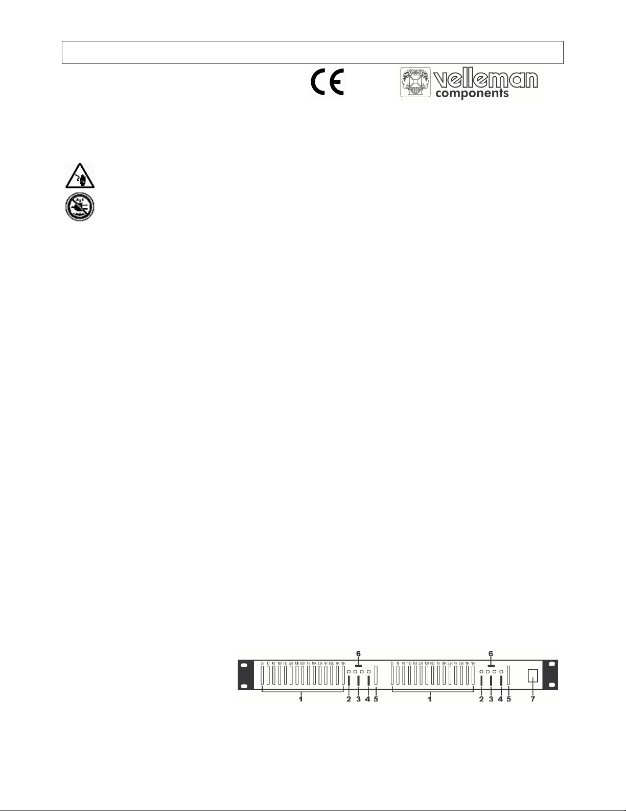
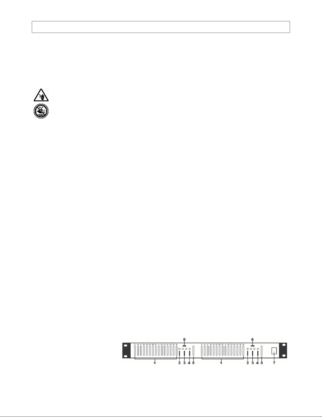
a. Front Panel - Commands
1. EQ level controls
2. EQ on/off button
3. EQ Range selection (6/12dB)
4. Low cut button (sets 30Hz to -6dB)
5. Channel level control
6. Peak indicator (red LED): lower the level (#5) if this LED remains lit continuously.
7. On/off switch
Fig.1
VDL215EQ 1 VELLEMAN
Page 2

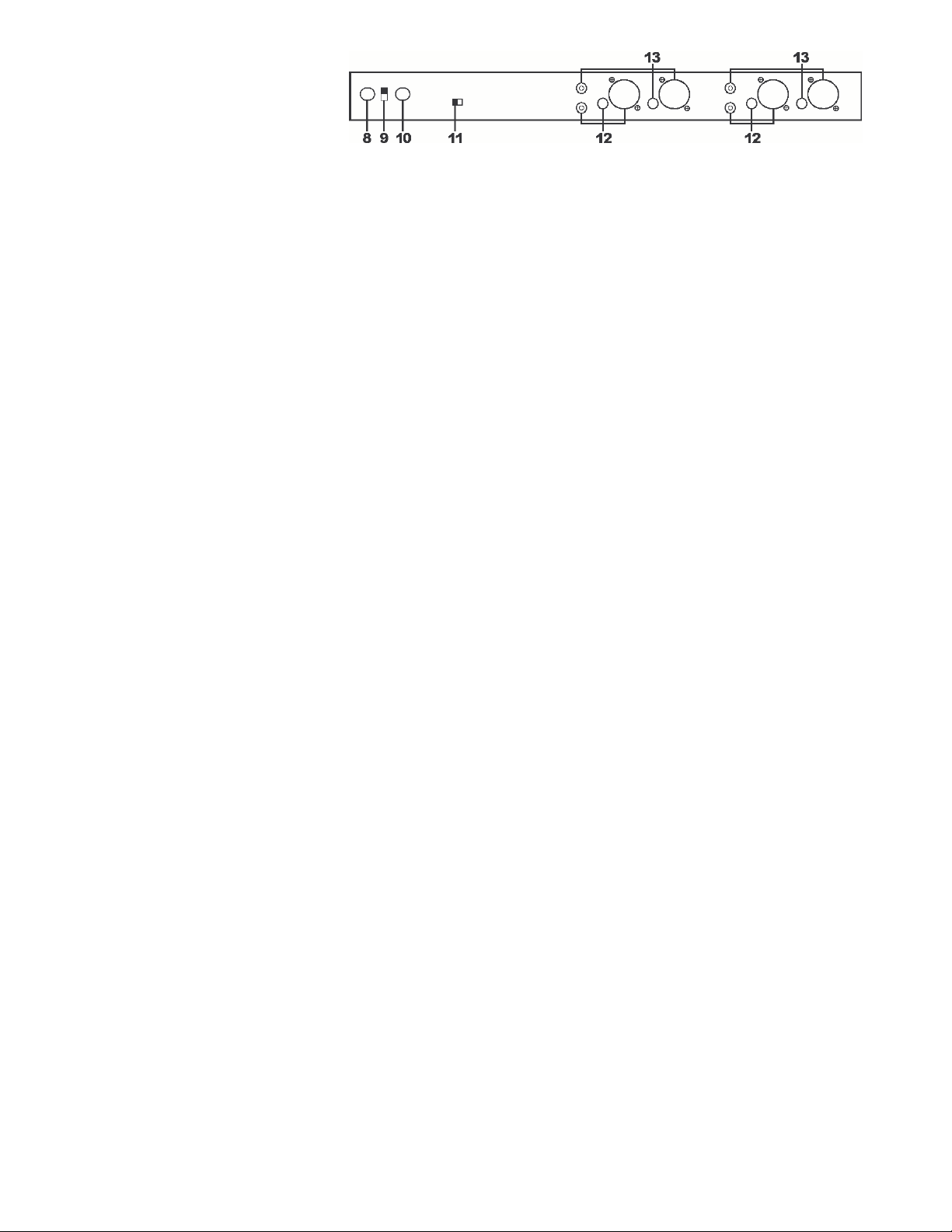
b. Rear Panel – Connections
8. Power cord
9. 110/220V power switch
10. Fuse holder
11. Ground lifting switch: to disconnect the signal ground from chassis ground
12. Output connectors (RCA, XLR and 6.3mm = ¼"TRS)
13. Input connectors (RCA, XLR and 6.3mm = ¼"TRS)
The RCA connections are unbalanced: pin = Hi (+) and sleeve = ground.
The TRS (Tip Ring Sleeve) connectors are balanced and wired as tip = Hi (+), ring = Lo (-) and sleeve = ground.
For unbalanced operation, use the tip as Hi (+) and the sleeve as ground.
The XLR connectors are balanced and wired as pin1 = ground, pin2 = Hi (+) and pin3 = Lo (-).
For unbalanced operation, use pin 2 as Hi (+) and pin 1 as ground.
Fig.2
6. Signal Levels
Signal levels from –10dBu to +4dBu are considered normal and there is a minimum tolerance of 20dB above these.
Never connect a microphone directly to an equalizer. Microphones have to be connected to a preamplifier first.
7. Chassis Grounding
The rear panel of this unique equalizer is equipped with a ground-lifting switch. Excessive humming or buzzing once
the system has been installed indicates a ground incompatibility between your equalizer and the other equipment in
the system. Several combinations can be attempted. Note: ALWAYS TURN OFF YOUR AMPLIFIERS BEFORE
CHANGING GROUND. Try different combinations on units equipped with ground-lifting switches or make sure that
all chassis are connected to earth ground through the mounting screws fixing the front panel to the rack.
8. Operating instructions
The equalizer is equipped with an activation switch (fig.1 #2) with a LED indicator. When the activation switch is ON,
the red LED will be lit and the equalizer settings will be used. When the switch is off, the red LED is off and the
device is in bypass mode: the signal will flow through at unity gain.
Also included is a 6/12dB range selection switch (fig.1 #3): the 6dB range has a green LED, the 12dB range a red one.
A 'low cut' switch (fig.1 #4) is provided as well: this switch sets the 30Hz level to -6dB.
A level control slider (fig.1 #5) controls the output with its range of -∞ to +6dB.
Note: In case of excessive gain, the red peak LED (fig.1 #6) will light up when the signal comes to within 3dB of the
clipping level. There is no problem if this occurs occasionally and the LED only flashes from time to time ; if the LED
is lit continuously, the user should readjust the level control. Below are some tips for the initial setup.
1. Put the channel level controls (fig.1 #5) on the front panel on the central indentation (0dB).
2. Put the equalizer in the bypass position.
3. Put all slide controls on the central indentation (0dB).
4. Select the 6dB range (fig.1 #3 ; green LED on).
5. Apply a signal to the system.
6. Engage the equalizer mode.
7. If the PEAK (overload) LED is lit : turn down the level control.
8. You may now start equalizing your system.
9. Switch to the 12dB range (red LED is lit) if the 6db range does not provide sufficient gain.
VDL215EQ 2 VELLEMAN
Page 3

9. Cleaning and Maintenance
1. All screws should be tightened and free of corrosion.
2. The housing and visible parts should not be deformed, modified or tampered with.
3. The electric power supply cables must not show any damage. Have a qualified technician maintain the device.
4. Disconnect the device from the mains prior to maintenance activities.
5. Wipe the device regularly with a moist, lint-free cloth. Do not use alcohol or solvents.
6. There are no user-serviceable parts, apart from the fuse.
10. Technical Specifications
Equalizer Bands 2 x 15, ISO Spacing, 25Hz to 16KHz
Equalizer Type Constant Q
Equalizer Travel 20mm (central indentation)
Equalizer Range +/-6dB or +/-12dB (selectable)
Inputs/Outputs RCA unbalanced
3-pin XLR actively balanced / unbalanced
6.3mm (1/4") TRS actively balanced / unbalanced
Input Impedance 20K Ohms Bal. ; 15K Ohms Unbal.
Maximum Input Level +22dBm (Level Control in central indentation)
Output Impedance Typ. < 150 Ohms
Maximum Output Level +22dBm (2K Ohms), +18dBm (600 Ohms)
PEAK LED Threshold 3dB (below clipping level)
Low-Cut Filter 30Hz, -6dB
Frequency Response 20Hz – 20KHz +/-1dB
THD + Noise <0.01% (20Hz – 20KHz +4dBm)
IM Distortion (SMPTE) <0.0005% (+4dBm)
Signal to Noise Ratio 110dB Below Max. Level (A-weighted)
Channel Separation 60dB (1KHz)
Line Voltage 200-240Vac, 50Hz/ 110Vac, 60Hz
Fuse 250Vac, 0.5A (order code FU0.5N)
Dimensions (WxHxD) 48.2x4.4x21cm = 19x1.75x8.2"
Weight 2.2kg = 4.8lbs
The information in this manual is subject to change without prior notice.
VDL215EQ 3 VELLEMAN
Page 4
VDL215EQ – 2 x 15-BANDS GRAFISCHE EQUALIZER
1. Inleiding
Dank u voor uw aankoop! Lees deze handleiding grondig voor u het toestel in gebruik neemt. Als het toestel werd
beschadigd tijdens het transport, installeer het dan niet en raadpleeg uw dealer.
2. Veiligheidsinstructies
Wees voorzichtig bij de installatie: raak geen kabels aan die onder stroom staan om
dodelijke elektroshocks te vermijden.
Bescherm dit toestel tegen regen en vochtigheid.
• De garantie geldt niet voor schade door wijzigingen aan het toestel of door het negeren van de richtlijnen in deze
handleiding. Uw dealer zal de verantwoordelijkheid afwijzen voor gerelateerde defecten of problemen.
• Laat dit toestel installeren en onderhouden door een geschoolde technicus.
• Om beschadiging te vermijden, zet u het toestel best niet aan onmiddellijk nadat het werd blootgesteld aan
temperatuurschommelingen. Wacht tot het toestel op kamertemperatuur gekomen is.
• De beschikbare netspanning mag niet hoger zijn dan de spanning in de specificaties achteraan de handleiding.
• De voedingskabel mag niet omgeplooid of beschadigd zijn. Laat uw dealer zo nodig een nieuwe kabel plaatsen.
• Trek de stekker uit het stopcontact (trek nooit aan de kabel!) voor u het toestel reinigt en als u het niet gebruikt.
• Hou dit toestel uit de buurt van kinderen en onbevoegden.
3. Algemene Richtlijnen
• Dit toestel is ontworpen voor professioneel gebruik in disco's enz. U mag dit toestel enkel binnenshuis gebruiken
door het aan te sluiten op een wisselspanning van maximum 230Vac/50Hz.
• Schud het toestel niet dooreen. Vermijd brute kracht tijdens de installatie en de bediening van dit toestel.
• Bescherm het toestel tegen extreme temperaturen (zie “10. Technische specificaties”), vochtigheid en stof.
• Leer eerst de functies van het toestel kennen voor u het gaat gebruiken. Ongeschoolde personen mogen dit
toestel niet gebruiken. Meestal is beschadiging het gevolg van onprofessioneel gebruik.
• Gebruik de oorspronkelijke verpakking wanneer u het toestel vervoert.
• Om veiligheidsredenen mag de gebruiker geen wijzigingen aanbrengen aan het toestel.
• Gebruik het toestel enkel waarvoor het gemaakt is. Bij onoordeelkundig gebruik vervalt de garantie.
4. Installatie
• De VDL215EQ is ontworpen voor montage in een standaard 19" rack of in een draagbare koffer.
• Installeer dit toestel op een plaats waar niemand het kan aanraken en waar niet veel mensen voorbijkomen.
5. Bedieningsknoppen en aansluitingen
a. Voorzijde - Bediening
1. EQ niveauregelaars
2. Drukknop EQ aan/uit
3. Selectie bereik EQ (6/12dB)
4. 'Low cut'-knop (zet 30Hz op -6dB)
5. Regeling geluidsniveau van het kanaal
6. Peak indicator (rode LED): zet het volume lager (#5) als deze LED continu oplicht.
7. On/off-schakelaar
Fig.1
VDL215EQ 4 VELLEMAN
Page 5
b. Achterzijde – Aansluitingen
8. Voedingskabel
9. Spanningschakelaar 110/220V
10. Zekeringhouder
11. 'Ground lifting' schakelaar: om de aarde van het signaal te scheiden van die van het toestel
12. Uitgangaansluitingen (RCA, XLR en 6.3mm = ¼"TRS)
13. Ingangaansluitingen (RCA, XLR en 6.3mm = ¼"TRS)
De RCA aansluitingen zijn niet gebalanceerd: pin = Hi (+) en de 'sleeve' = massa.
De TRS (Tip Ring Sleeve) aansluitingen zijn gebalanceerd met tip = Hi (+), ring = Lo (-) en 'sleeve' = massa.
Voor niet-gebalanceerde aansluiting wordt dit tip = Hi (+) en 'sleeve' = massa.
De XLR aansluitingen zijn gebalanceerd met pin1 = massa, pin2 = Hi (+) en pin3 = Lo (-).
Voor niet-gebalanceerde aansluiting wordt dit pin 2 = Hi (+) en pin 1 = massa.
Fig.2
6. Volume van het signaal
Volumes van –10dBu tot +4dBu worden als normaal beschouwd en het toestel heeft een tolerantie van minimum
20dB boven deze niveaus. Verbind een microfoon nooit rechtstreeks met een equalizer. Een microfoon moet altijd
eerst naar een voorversterker gaan.
7. Massa van het chassis
Het achterpaneel van de equalizer is uitgerust met een massa-ontkoppelingsschakelaar. Wanneer het systeem na
de installatie te veel brom- of zoemgeluiden produceert, wil dit zeggen dat de massa van de equalizer onverenigbaar
is met de massa van de andere toestellen van uw systeem. U kunt verschillende combinaties uitproberen. Let wel:
SCHAKEL DE VERSTERKERS UIT VÓÓR U DE MASSA WIJZIGT. Probeer verschillende combinaties uit met
toestellen die uitgerust zijn met een massa-ontkoppelingsschakelaar of zorg er voor dat alle behuizingen geaard zijn
via de schroeven waarmee het frontpaneel op het rack vastzit.
8. Bedieningsinstructies
De equalizer beschikt over een activeringsschakelaar (fig.1 #2) met LED-indicator. Wanneer de schakelaar op ON
staat, brandt de rode LED en worden de instellingen van de equalizer gebruikt. Staat de schakelaar niet aan, dan
brandt de LED niet en staat het toestel in "bypass": het signaal wordt ongewijzigd doorgestuurd naar de uitgang.
De VDL215EQ heeft ook een keuzeschakelaar voor het bereik (fig.1 #3): 6dB (groene LED) of 12dB (rode LED).
Ook een 'Low cut'-schakelaar (fig.1 #4) is voorzien: hiermee zet u de frequenties rond 30Hz op -6dB.
U beschikt ook over een volumeregelaar (fig.1 #5) met een bereik van -∞ tot +6dB.
Opmerking: Bij te grote versterking zal de rode piek LED (fig.1 #6) knipperen wanneer het signaal het piekniveau tot
op 3dB benadert. Er is geen probleem als de LED zo nu en dan knippert, maar de gebruiker moet het volume
aanpassen wanneer de LED doorlopend brandt. Hieronder vindt u enkele tips om uw systeem af te stellen:
1. Plaats de draairegelingen voor het kanaalniveau in de neutrale stand (0dB). U vindt ze op het frontpaneel.
2. Plaats de equalizer in de bypass stand.
3. Plaats alle schuifregelaars in de neutrale stand (0dB).
4. Selecteer het 6dB bereik (fig.1 #3 ; groene LED brandt).
5. Stuur het signaal door het systeem.
6. Schakel de equalizer mode in.
7. Indien de PEAK LED (overbelasting) oplicht: verminder het volume.
8. U kunt de equalizer nu bijregelen.
9. Schakel over op het 12dB bereik (rode LED) indien het 6dB bereik voor onvoldoende versterking zorgt.
VDL215EQ 5 VELLEMAN
Page 6

9. Reiniging en onderhoud
1. Alle gebruikte schroeven moeten goed zijn aangespannen en mogen geen sporen van roest vertonen.
2. De behuizing en zichtbare onderdelen mogen niet vervormd zijn of aangepast worden.
3. De voedingskabels mogen niet beschadigd zijn. Laat het toestel onderhouden door een geschoolde technicus.
4. Ontkoppel het toestel van het lichtnet voor u aan onderhoudswerkzaamheden begint.
5. Maak het toestel geregeld schoon met een vochtige, niet pluizende doek. Gebruik geen alcohol of solvent.
6. De gebruiker mag geen onderdelen vervangen op de zekering na.
10. Technische specificaties
Equalizerbanden 2 x 15, ISO Spacing, 25Hz tot 16KHz
Type Equalizer Constant Q
Regelhoogte 20mm (neutrale stand)
Bereik Equalizer +/-6dB of +/-12dB (selecteerbaar)
Ingangen/uitgangen RCA niet gebalanceerd
3-pin XLR actief gebalanceerd / ongebalanceerd
6.3mm (1/4") TRS actiefl gebalanceerd / ongebalanceerd
Ingangimpedantie 20K Ohms gebal. ; 15K Ohms ongebal.
Maximum ingangsniveau +22dBm (Niveauregelaar in neutrale stand)
Uitgangimpedantie Typ. < 150 Ohms
Maximum uitgangsniveau +22dBm (2K Ohms), +18dBm (600 Ohms)
Peak (piek) LED drempel 3dB (onder piekniveau)
High-Pass Filter 20Hz, -18dB/Octaaf
Frequentieweergave 20Hz – 20KHz +/-1dB
THD + Lawaai <0.01% (20Hz – 20KHz +4dBm)
IM Distorsie (SMPTE) <0.0005% (+4dBm)
Signaal/ruisverhouding 110dB onder max. niveau (A-gewogen)
Kanaalscheiding 60dB (1KHz)
Voedingsspanning 200-240Vac, 50Hz / 110Vac, 60Hz
Zekering 250Vac, 0.5A (bestelcode FU0.5N)
Afmetingen (BxHxD) 48,2cm x 4,4cm x 21cm
Gewicht 2.2kg
De informatie in deze handleiding kan te allen tijde worden gewijzigd zonder voorafgaande kennisgeving.
VDL215EQ 6 VELLEMAN
Page 7

VDL215EQ – EGALISEUR GRAPHIQUE A 2 x 15 BANDES
1. Introduction
Nous vous remercions de votre achat ! Lisez le présent manuel attentivement avant la mise en service de l'appareil.
Si l’appareil a été endommagé pendant le transport, ne l'installez pas et consultez votre revendeur.
2. Prescriptions de sécurité
Soyez prudent lors de l'installation : toucher un câble sous tension peut causer des électrochocs mortels.
Protégez l'appareil contre la pluie et l'humidité.
• La garantie ne s'applique pas aux dommages par des modifications à l'appareil ou par la négligence des directives
de ce manuel. Votre revendeur déclinera toute responsabilité pour les problèmes et défauts qui en résultent.
• Un technicien qualifié doit s'occuper de l'installation et de l’entretien.
• Ne branchez pas l'appareil après exposition à des variations de température. Afin d’éviter des dommages,
attendez jusqu’à ce que l'appareil ait atteint la température ambiante avant de l'utiliser.
• La tension réseau ne peut pas dépasser la tension mentionnée dans les spécifications à la fin de ce manuel.
• Le câble d'alimentation ne peut pas être replissé ou endommagé. Votre revendeur peut le renouveler si nécessaire.
• Débranchez l’appareil s’il n’est pas utilisé ou pour le nettoyer. Tirez la fiche pour le débrancher; non pas le câble.
• Gardez votre VDL215EQ hors de la portée de personnes non qualifiées et de jeunes enfants.
3. Directives générales
• Cet appareil a été développé pour usage professionnel dans des discothèques, des théâtres, etc. Employez cet
appareil à l'intérieur et avec une source de courant CA de max. 230Vac/50Hz.
• Evitez de secouer l'appareil et traitez l'appareil avec circonspection pendant l'installation et l'opération.
• Choisissez un endroit où l’appareil est protégé contre la poussière, l’humidité et des températures extrêmes.
• Familiarisez-vous avec le fonctionnement de l'appareil avant de l’utiliser. Ne permettez pas aux personnes non
qualifiées d'opérer cet appareil. La plupart des dégâts sont causés par un usage non professionnel.
• Transportez l'appareil dans son emballage originel.
• Toute modification de l’appareil est interdite pour des raisons de sécurité.
• N’utilisez votre VDL215EQ qu’à sa fonction prévue. Un usage impropre annule d'office la garantie.
4. Installation
• Cet égaliseur est conçu pour être monté dans un rack standard de 19" ou dans un coffret portable.
• Installez l’appareil hors de portée des personnes non autorisées. Evitez les endroits populeux.
5. Boutons et connexions
a. Panneau frontal - boutons
1. Glissières niveau d'égalisation
2. Bouton égaliseur on/off
3. Sélecteur portée d'égalisation (6/12dB)
4. Bouton pour coupage des fréquences basses ("Low cut": met les fréquences autour du 30Hz à -6dB)
5. Glissière pour niveau de volume du canal
6. Témoin Peak (surcharge) (LED rouge): baissez le niveau (#5) quand cette LED est illuminée en continu.
7. Interrupteur
Fig.1
VDL215EQ 7 VELLEMAN
Page 8

b. Panneau arrière – Connexions
8. Fil d'alimentation
9. Sélecteur 110/220V
10. Porte-fusible
Fig.2
11. Commutateur de déconnexion de masse: pour débrancher la masse du signal du châssis mis à la terre
12. Connecteurs de sortie (RCA, XLR et 6.3mm = ¼"TRS)
13. Connecteurs d'entrée (RCA, XLR et 6.3mm = ¼"TRS)
Les connecteurs RCA sont non balancés: broche = Hi (+) et manche = masse.
Les connecteurs TRS (Tip Ring Sleeve) sont balancés: pointe = Hi (+), anneau = Lo (-) et manche = masse.
Pour connexion non balancée, pointe = Hi (+) et la manche sert comme masse.
Les connecteurs XLR sont balancés et câblés: broche1 = masse, broche 2 = Hi (+) et broche 3 = Lo (-).
Pour connexion non balancée, broche2 = Hi (+) et broche1 = masse.
6. Volume du signal
Des volumes de –10dBu à +4dBu sont considérés normales et l'appareil a une tolérance min. de 20dB au-dessus de
ces niveaux-là. Ne connectez jamais un microphone directement sur un égaliseur. Un microphone doit d'abord être
connecté à un préamplificateur.
7. Masse du châssis
Le panneau arrière de l'égaliseur est équipé d'un commutateur de déconnexion de masse. Il se peut toujours que le
système produise trop de ronflement après son installation. Ceci indique que la masse de l'égaliseur est incompatible
avec les autres appareils du système. Il y a plusieurs combinaisons que vous pouvez essayer. Remarquez qu'il faut
ETEINDRE LES AMPLIFICATEURS AVANT DE CHANGER LA MASSE. Essayez plusieurs combinaisons avec des
appareils équipés d'un commutateur de déconnexion de masse ou vérifiez si tous les châssis sont mis à la terre via
les vis du rack du panneau frontal.
8. Instructions de commande
L'égaliseur dispose d'un commutateur d'activation (fig.1 #2) avec un indicateur LED. Quand le commutateur est ON,
la LED rouge s’allume et les réglages de l'égaliseur sont utilisés. Si le commutateur est OFF, l'appareil est en mode
'bypass' et le signal d'entrée est immédiatement envoyé à la sortie.
Vous pouvez modifier la portée des glissières (fig.1 #3): 6dB (LED verte) ou 12dB (LED rouge).
Il y a également une fonction 'Low cut' (coupage des fréquences basses – fig.1 #4) qui met le niveau 30Hz à -6dB.
L'appareil est équipé d'un réglage de volume par canal (fig.1 #5) dont la plage est de -∞ à +6dB.
Remarque: En cas de gain excessif, la LED de pointe rouge clignotera lorsque le signal atteint une intensité sonore
de 3dB en dessous du niveau "peak" (pointe). Il n'y a aucun problème si cette intensité sonore est atteinte de temps
en temps (LED clignote). Si, par contre, la LED reste allumée constamment, l'utilisateur doit diminuer le volume.
Quelques tuyaux utiles pour installer et régler votre système :
1. Mettez les glissières pour le niveau des canaux (fig.1 #5) dans la position neutre (0dB).
2. Mettez l’égaliseur dans le mode bypass (fig.1 #2).
3. Mettez toutes les glissières dans la position neutre (0dB).
4. Sélectionnez la plage 6dB (fig.1 #3 - LED verte s’allume).
5. Appliquez le signal au système.
6. Quittez le mode bypass.
7. Si la LED PEAK (surcharge) s’allume: diminuez le volume.
8. L'égaliseur peut maintenant être réglé.
9. Sélectionnez la plage 12dB (LED rouge s'allume) si le gain livré par la plage de 6dB est insuffisant.
VDL215EQ 8 VELLEMAN
Page 9

9. Nettoyage et entretien
1. Serrez les écrous et les vis et vérifiez qu'ils ne rouillent pas.
2. Le boîtier et les parties visibles ne peuvent pas être déformés, adaptés ou bricolés.
3. Les câbles d'alimentation ne peuvent pas être endommagés. Un technicien qualifié doit entretenir l’appareil.
4. Débranchez l'appareil avant de le nettoyer.
5. Essuyez l'appareil régulièrement avec un chiffon humide non pelucheux. Evitez l'usage d'alcool et de solvants.
6. Il n’y a pas de parties maintenables par l’utilisateur à part le fusible.
7. Commandez des pièces de rechange éventuelles chez votre revendeur.
10. Spécifications techniques
Bandes égaliseur 2 x 15, Espacement ISO, 25Hz à 16KHz
Type égaliseur Constant Q
Hauteur glissières 20mm (avec position neutre)
Plage glissières +/-6dB of +/-12dB (commutable)
Entrées/sorties RCA non balancé
XLR à 3 broches, activement balancé / non balancé
6.3mm (1/4") TRS activement balancé / non balancé
Impédance d'entrée 20K Ohms bal. ; 15K Ohms non bal.
Niveau d'entrée max. +22dBm (en position neutre)
Impédance de sortie Typ. < 150 Ohms
Niveau de sortie max. +22dBm (2K Ohms), +18dBm (600 Ohms)
Seuil d'activation de la LED PEAK 3dB (sous niveau PEAK)
Filtre Low cut 30Hz, -6dB
Réponse en fréquence 20Hz – 20KHz +/-1dB
THD + Bruit <0.01% (20Hz – 20KHz +4dBm)
Distorsion IM (SMPTE) <0.0005% (+4dBm)
Rapport S/B 110dB sous niveau max.(pondéré en A)
Séparation des canaux 60dB (1KHz)
Tension d'alimentation 200-240Vca, 50Hz / 110Vca, 60Hz
Fusible 250Vca, 0.5A (référence FU0.5N)
Dimensions (LaxHxP) 48,2cm x 4,4cm x 21cm
Poids 2.2kg
Toutes les informations présentées dans ce manuel peuvent être modifiées sans notification préalable.
VDL215EQ – ECUALIZADOR GRÁFICO DE 2 x 15 BANDAS
1. Introducción
¡Gracias por haber comprado el VDL215EQ! Lea cuidadosamente las instrucciones del manual antes de usarlo.
Si el aparato ha sufrido algún daño en el transporte no lo instale y póngase en contacto con su distribuidor.
2. Instrucciones de seguridad
Cuidado durante la instalación: puede sufrir una peligrosa descarga eléctrica al tocar los cables con un
voltaje peligroso
No exponga este equipo a lluvia o humedad.
VDL215EQ 9 VELLEMAN
Page 10

• Daños causados por descuido de las instrucciones de seguridad de este manual invalidarán su garantía y su
distribuidor no será responsable de ningún daño u otros problemas resultantes.
• La instalación y el mantenimiento deben ser realizados por personal especializado.
• No conecte el aparato si ha estado expuesto a grandes cambios de temperatura. Espere hasta que el aparato
llegue a la temperatura ambiente.
• Asegúrese de que la tensión de red no sea mayor que la tensión indicada en las especificaciones.
• No aplaste el cable de alimentación y protéjalo contra posibles daños causados por algún tipo de superficie
afilada. Si es necesario, pida a su distribuidor reemplazar el cable de alimentación.
• Desconecte siempre el aparato si no va a usarlo durante un largo periodo de tiempo o antes de limpiarlo. Tire
siempre del enchufe para desconectar el cable de red, nunca del propio cable.
• Mantenga el VDL215EQ lejos del alcance de personas no autorizadas y niños.
3. Normas generales
• Este aparato ha sido diseñado para un uso profesional en discotecas, teatros, etc. Utilice este aparato en
interiores y conectado a una fuente de corriente CA de máx. 230Vac/50Hz.
• No agite el aparato. Evite usar excesiva fuerza durante la instalación y la reparación.
• Seleccione un lugar de montaje donde el aparato no esté expuesto a polvo, humedad y calor extremo.
• Familiarícese con el funcionamiento del aparato. Sólo personas cualificadas pueden operar con este aparato. La
mayoría de los daños son causados por un uso inadecuado.
• Transporte el aparato en su embalaje original.
• Por razones de seguridad, las modificaciones no autorizadas del aparato están prohibidas.
• Utilice sólo el VDL215EQ para aplicaciones descritas en este manual. Un uso desautorizado puede causar daños
y anula la garantía completamente.
4. Instalación
• Este ecualizador ha sido diseñado para montarlo en un rack estándar de 19" o en una caja portátil.
• Instale el aparato fuera del alcance de personas no autorizadas y en un lugar con poca gente.
5. Botones y conexiones
a. Panel frontal - botones
1. Deslizadores para el ajuste del
nivel EQ
2. Botón ecualizador ON/OFF
3. Selector para el alcance EQ (6/12dB)
4. Botón para cortar las frecuencias bajas ("Low cut": pone las frecuencias de 30Hz a -6dB)
5. Deslizador para el nivel de volumen del canal
6. Indicador Peak (sobrecarga) (LED rojo): disminuya el nivel (#5) si este LED se ilumina de forma continua.
7. Interruptor
b. Panel trasero – Conexiones
8. Cable de alimentación
9. Selector 110/220V
10. Portafusible
11. Conmutador de desconexión de masa: para desconectar la masa de la señal del chasis puesto a tierra
12. Conectores de salida (RCA, XLR y 6.3mm = ¼"TRS)
13. Conectores de entrada (RCA, XLR y 6.3mm = ¼"TRS)
Fig.1
Fig.2
VDL215EQ 10 VELLEMAN
Page 11

Los conectores RCA no están balanceados: polo = Hi (+) y funda = masa.
Los conectores TRS (Tip Ring Sleeve) están balanceados: punta = Hi (+), anillo = Lo (-) y funda = masa.
Para una conexión no balanceada, punta = Hi (+) y la funda sirve de masa.
Los conectores XLR están balanceados y cableados: polo 1 = masa, polo 2 = Hi (+) y polo 3 = Lo (-).
Para una conexión no balanceada, polo2 = Hi (+) y polo1 = masa.
6. Volumen de la señal
Los volúmenes de –10dBu a +4dBu se consideran normales y el aparato tiene una tolerancia mín. de 20dB encima
de estas niveles. Nunca conecte un micrófono directamente a un ecualizador. Primero, conecte un micrófono a un
preamplificador.
7. Masa del chasis
El panel trasero del ecualizador está equipado con un conmutador de desconexión de masa. Siempre es posible que
el sistema produzca demasiado zumbido e interferencias después de la instalación. Esto indica que la masa del
ecualizador es incompatible con los otros aparatos del sistema. Hay varias combinaciones que puede intentar.
Tenga en cuenta que debe DESACTIVAR LOS AMPLIFICADORES ANTES DE CAMBIAR LA MASA. Intente varias
combinaciones con aparatos equipados de un conmutador de desconexión de masa o verifique si todos los chasis
están puestos a tierra a través de los tornillos del rack del panel frontal.
8. Manual del usuario
El ecualizador tiene un conmutador de activación (fig.1 #2) con un indicador LED. Si el conmutador está activado
(ON), el LED rojo se ilumina y los ajustes del ecualizador se utilizan. Si el conmutador está desactivado (OFF), el
aparato está en modo 'bypass': la señal de entrada se envía inmediatamente a la salida.
Puede modificar el alcance de los deslizadores (fig.1 #3): 6dB (LED verde) o 12dB (LED rojo).
También hay una función 'Low cut' (cortar las frecuencias bajas – fig.1 #4) que pone el nivel de 30Hz a -6dB.
El aparato está equipado con un ajuste de volumen por canal (fig.1 #5) cuyo alcance es de -∞ a +6dB.
Observación: En caso de una ganancia excesiva, el LED "peak" (pico) rojo parpadeará si la señal llega a una
intensidad sonora de 3dB debajo del nivel "peak". No hay ningún problema si llega a esta intensidad sonora de vez
en cuando (LED parpadea). Si, al contrario, el LED queda iluminado de forma continua, disminuya el volumen. A
continuación están algunos consejos útiles para instalar y ajustar su sistema:
1. Coloque los deslizadores para el nivel de los canales (fig.1 #5) en la posición neutral (0dB).
2. Coloque el ecualizador en el modo "bypass" (fig.1 #2).
3. Coloque todos los deslizadores en la posición neutral (0dB).
4. Seleccione el rango 6dB (fig.1 #3 - LED verde se ilumina).
5. Envíe la señal por el sistema.
6. Salga del modo "bypass".
7. Si el LED PEAK (sobrecarga) se ilumina: disminuya el volumen.
8. Ahora, puede ajustar el ecualizador.
9. Seleccione el rango 12dB (LED rojo se ilumina) si la ganancia suministrada por el rango de 6dB no es suficiente.
9. Limpieza y mantenimiento
1. Apriete bien las tuercas y los tornillos y verifique que no hay señales de oxidación.
2. No modifique la caja, los soportes y las conexiones, etc.
3. No dañe los cables de alimentación. Contacte con un técnico especializado para instalar el aparato.
4. Desconecte el aparato de toda fuente antes de limpiarlo.
5. Limpie el aparato regularmente con un paño húmedo sin pelusas. Evite el uso de alcoholes y disolventes.
6. Sólo se puede reemplazar el fusible.
7. Contacte con su distribuidor si necesita piezas de recambio.
VDL215EQ 11 VELLEMAN
Page 12

10. Especificaciones
Bandas ecualizador 2 x 15, Espaciado ISO, de 25Hz a 16KHz
Tipo de ecualizador Q constante
Altura deslizadores 20mm (en posición neutral)
Alcance ecualizador +/-6dB o +/-12dB (conmutable)
Entradas/salidas RCA sin balancear
XLR de 3 polos, activamente balanceado / sin balancear
6.3mm (1/4") TRS activamente balanceado / sin balancear
Impedancia de entrada 20K Ohms balanceado ; 15K Ohms sin balancear
Nivel de entrada máx. +22dBm (en posición neutral)
Impedancia de salida Típ. < 150 Ohms
Nivel de salida máx. +22dBm (2K Ohms), +18dBm (600 Ohms)
Umbral de activación del LED PEAK 3dB (bajo el nivel PEAK)
Filtro "Low cut" 30Hz, -6dB
Respuesta en frecuencia 20Hz – 20KHz +/-1dB
THD + ruido <0.01% (20Hz – 20KHz +4dBm)
Distorsión IM (SMPTE) <0.0005% (+4dBm)
Relación señal / ruido 110dB bajo el nivel máx. (ponderado en A)
Separación de los canales 60dB (1KHz)
Tensión de alimentación 200-240Vca, 50Hz / 110Vca, 60Hz
Fusible 250Vca, 0.5A (referencia FU0.5N)
Dimensiones (AnxAlxP) 48,2cm x 4,4cm x 21cm
Peso 2.2kg
Se pueden modificar las especificaciones y el contenido de este manual sin previo aviso.
VDL215EQ – 2 X 15-BAND GRAPHISCHER EQUALIZER
1. Einführung
Danke für den Kauf des VDL215EQ! Bitte lesen Sie vor Inbetriebnahme diese Bedienungsanleitung sorgfältig durch.
Überprüfen Sie, ob Transportschäden vorliegen. Sollte dies der Fall sein, verwenden Sie das Gerät nicht und wenden
Sie sich an Ihren Händler.
2. Sicherheitsvorschriften
Seien Sie während der Installation des Gerätes sehr vorsichtig: das Berühren von unter Spannung
stehenden Leitungen könnte zu lebensgefährlichen elektrischen Schlägen führen.
Keinem Regen oder keiner Feuchte aussetzen.
• Bei Schäden, die durch Nichtbeachtung der Bedienungsanleitung verursacht werden, erlischt der
Garantieanspruch. Für daraus resultierende Folgeschäden übernimmt der Hersteller keine Haftung.
• Installation und Wartung sind einer autorisierten Fachkraft vorbehalten.
• Schalten Sie das Gerät nicht direkt ein wenn es Temperaturschwankungen ausgesetzt wurde. Um Schaden zu
vermeiden, schalten Sie das Gerät nicht an bevor es Zimmertemperatur erreicht hat.
• Vergewissern Sie sich, dass die anzuschließende Netzspannung nicht höher ist als die in dieser
Bedienungsanleitung erwähnte Netzspannung.
• Crimpen Sie das Stromkabel nicht und schützen Sie es vor Beschädigung. Lassen Sie, falls nötig, das Kabel von
einem Fachmann ersetzen.
VDL215EQ 12 VELLEMAN
Page 13

• Trennen Sie das Gerät bei Nichtbenutzung und vor jeder Reinigung vom Netz. Fassen Sie dazu den Netzstecker
an der Grifffläche an und ziehen Sie nie an der Netzleitung.
• Von Kindern und Unbefugten fern halten.
3. Allgemeine Richtlinien
• Dieses Gerät ist für den professionellen Einsatz in Discotheken, Theatern usw. konzipiert worden. Der VDL215EQ
darf nur im Innenbereich und bei einer Wechselspannung von max. 230V AC/50Hz verwendet werden.
• Vermeiden Sie Erschütterungen. Vermeiden Sie rohe Gewalt während der Installation und Bedienung des
Gerätes.
• Achten Sie bei der Wahl des Installationsortes darauf, dass das Gerät keinem Staub, keiner Feuchtigkeit und
extremen Temperaturen ausgesetzt wird (siehe "10. Technische Daten").
• Nehmen Sie das Gerät erst in Betrieb, nachdem Sie sich mit seinen Funktionen vertraut gemacht haben. Lassen
Sie das Gerät nicht von Personen bedienen, die sich nicht mit dem Gerät auskennen. Meist ist die Beschädigung
des Gerätes das Ergebnis von unfachmännischer Bedienung.
• Verwenden Sie die Originalverpackung, wenn das Gerät transportiert werden soll.
• Verwenden Sie das Gerät nur für Anwendungen beschrieben in dieser Bedienungsanleitung sonst kann dies zu
Schäden am Produkt führen und erlischt der Garantieanspruch. Jede andere Verwendung ist mit Gefahren wie
Kurzschluss, Brandwunden, elektrischem Schlag, Lampenexplosion, usw. verbunden.
4. Installation
• Der VDL215EQ wurde zur Montage in einem gängigen 19" Rack oder tragbaren Gehäuse entworfen.
• Montieren Sie das Gerät an einer Stelle, an der es wenig Vorübergehende gibt und unzugänglich für Unbefugte
ist.
5. Befehle und Anschlüsse
a. Frontplatte - Befehle
1. EQ-Pegel Bedienelemente
2. EQ EIN/AUS-Taste
3. EQ-Bereichsauswahl (6/12dB)
4. 'Low Cut'-Taste (von 30Hz bis -
6dB)
5. Lautstärkeregelung des Kanals
6. Spitzenanzeige (rote LED): senken Sie den Pegel wenn diese LED Ständig brennt (#5).
7. EIN-/AUS-Schalter
b. Rückplatte - Anschlüsse
8. Stromkabel
9. 110/220V EIN/AUS-Schalter
10. Sicherungshalter
11. 'Ground Lifting'-Schalter: um die Signalmasse von der Chassismasse zu trennen.
12. Ausgangsanschlüsse (RCA (Cinch), XLR und 6.3mm = ¼" TRS (Stereoklinkenanschlüsse)
13. Eingangsanschlüsse (RCA, XLR und 6.3mm = ¼"TRS)
Die RCA (Cinch)-Anschlüsse sind unsymmetrisch: Pin = Hi (+) und Sleeve = Masse.
Die (Tip Ring Sleeve) Stereoklinkenanschlüsse sind symmetrisch und verkabelt als Tip (Spitze) = Hi (+), Ring = Lo (-)
und Sleeve (Schaft) = Masse
Für unsymmetrischen Betrieb, verwenden Sie Tip als Hi (+) und Sleeve als Masse.
Abb. 1
Abb. 2
VDL215EQ 13 VELLEMAN
Page 14

Die XLR-Anschlüsse sind symmetrisch und verkabelt als Pin1 = Masse, Pin2 = Hi (+) und Pin3 = Lo (-).
Für unsymmetrischen Betrieb, verwenden Sie Pin 2 als Hi (+) und Pin 1 als Masse.
6. Signalpegel
Signalpegel (Lautstärke) von –10dBu bis +4dBu werden als normal betrachtet und es gibt eine minimale Toleranz
von 20dB über diesen Werten. Schließen Sie nie unmittelbar ein Mikrofon an einen Equalizer an; Mikrofone müssen
zuerst an einen Vorverstärker angeschlossen werden.
7. Chassismasse
Die Rückplatte dieses einzigartigen Equalizers ist mit einem 'Ground-Lifting'-Schalter ausgestattet. Überhöhtes
Gebrumm oder Summen wenn das System installiert ist, weist auf eine Masseninkompatibilität zwischen dem
Equalizer und anderen Geräten im System hin. Verschiedene Kombinationen können versucht werden. Hinweis:
SCHALTEN SIE IMMER DIE VERSTÄRKER AUS BEVOR SIE DIE MASSE ÄNDERN. Versuchen Sie verschiedene
Kombinationen bei Einheiten ausgestattet mit 'Ground-Lifting'-Schaltern und achten Sie darauf, dass alle Gehäuse
über die Schrauben, mit denen die Frontplatte am Rack befestigt sind, geerdet sind.
8. Bedienungsanweisungen
Der Equalizer ist mit einem Aktivierungsschalter (1) mit einer LED-Anzeige ausgestattet. Wenn der
Aktivierungsschalter auf ON steht, wird die rote LED brennen und werden die Equalizer-Einstellungen verwendet
werden. Wenn der Schalter aus steht, brennt die rote LED nicht und ist das Gerät im Bypass-Modus: das Signal wird
mit 'Einheitsverstärkung 'durchfließen' .
Auch gibt es einen 6/12dB Wahlschalter (Abb.1 #3): der 6dB-Bereich hat eine grüne LED, der 12dB-Bereich hat eine
rote.
Ein 'Low Cut' Schalter (Abb.1 #4) wird auch mitgeliefert. Dieser Schalter schaltet den 30Hz-Bereich auf -6dB.
Ein Schiebeschalter für die Lautstärkeregelung (Abb.1 #5) steuert den Ausgang mit einem Bereich von -∞ bis +6dB.
Hinweis: Bei einer sehr großen Verstärkung, wird die rote LED (Spitzenanzeige) (Abb.1 #6) aufleuchten wenn sich
das Signal bis auf 3dB dem Begrenzungspegel nähert. Das ist kein Problem wenn die LED nur ab und zu blinkt;
wenn die LED ständig brennt, muss der Benutzer die Lautstärke anpassen. Unten finden Sie einige Hinweise für die
Anfangskonfiguration.
1. Stellen Sie die Lautstärke der Kanäle (Abb.1 #5) auf die mittlere Markierung (0dB) auf der Frontplatte.
2. Stellen Sie den Equalizer in die Bypass-Position.
3. Stellen Sie alle Schiebeschalter auf die die mittlere Markierung (0dB).
4. Wählen Sie den 6dB-Bereich (Abb.1 #3 ; grüne LED eingeschaltet ).
5. Senden Sie dem System ein Signal
6. Aktivieren Sie den Equalizer-Modus
7. Wenn die Spitzenanzeige PEAK LED brennt: mindern Sie die Lautstärke
8. Jetzt können Sie Ihr System abstimmen
9. Schalten Sie auf den 12dB-Bereich um (rote LED brennt) wenn der 6db-Bereich nicht genügend Verstärkung
bietet.
9. Reinigung und Wartung
1. Alle Schrauben müssen fest angeschraubt sein und dürfen keine Rostspuren aufweisen.
2. Das Gehäuse und die sichtbaren Teile dürfen nicht deformiert, modifiziert oder unbefugt verwendet sein.
3. Die Stromkabel dürfen nicht beschädigt sein. Lassen Sie das Gerät von einem Techniker warten.
5. Reinigen Sie das Gerät regelmäßig mit einem feuchten, flusenfreien Tuch. Verwenden Sie keinen Alkohol oder
keine Lösungsmittel.
6. Es gibt keine wartbaren Teile, außer die Sicherung.
VDL215EQ 14 VELLEMAN
Page 15

10. Technische Daten
Equalizer Bandbreite 2 x 15, ISO Spacing, 25Hz bis 16KHz
Equalizertyp Constant Q
Equalizer Travel 20mm (central indentation)
Equalizerbereich +/-6dB or +/-12dB (selectable)
Eingänge/Ausgänge RCA unsymmetrisch
3-polig XLR aktiv symmetrisch/unsymmetrisch
6.3mm (1/4") TRS aktiv symmetrisch/unsymmetrisch
Eingangsimpedanz 20K Ohms Bal. ; 15K Ohms Unbal.
Maximaler Eingang +22dBm (Lautstärkeregelung/ mittlere Markierung)
Ausgangsimpedanz Typ. < 150 Ohm
Maximaler Ausgang +22dBm (2K Ohm), +18dBm (600 Ohm)
PEAK LED 3dB (unter Begrenzung)
Low-Cut Filter 30Hz, -6dB
Frequenzrespons 20Hz – 20KHz +/-1dB
THD + Geräusch <0.01% (20Hz – 20KHz +4dBm)
IM Verformung (SMPTE)<0.0005% (+4dBm)
Signal/Rauschabstand 110dB unter max. Pegel (A-bewertet)
Kanaltrennung 60dB (1KHz)
Netzspannung 200-240Vac, 50Hz/ 110Vac, 60Hz
Sicherung 250Vac, 0.5A (Artikelnummer FU0.5N)
Abmessungen (BxHxT) 48.2x4.4x21cm = 19x1.75x8.2"
Gewicht 2.2kg = 4.8lbs
Alle Änderungen vorbehalten
VDL215EQ 15 VELLEMAN
 Loading...