

Velleman NVR4 Quick Installation Manual
NVR4
EN
16-CH ANNEL HD NE TWOR K VID EO RECORDER – HDMI – ONVIF
– EAGLE EYES
NL
HD NETWERK VIDEORECORDE R M ET 16 KANALEN – HDMI –
ONVIF – EAGLE EYES
FR
ENREGISTREUR VIDÉO RÉS EAU H D À 16 CANAUX - HDMI -
ONVIF - EAGL E E YES
ES
GRABADOR DE VÍDEO EN R ED D E AL TA D EFI NIC IÓ N DE 16
CANALES - HDMI - ONVIF - EAG LE EYES
DE
16-K ANAL HOC HAU FLÖS EN DER N ET ZWER K-VIDEOREKORDER -
HDMI - ONVIF - EA GLE EYES
QUICK INSTA LLAT ION GUIDE 3
KORTE HANDLEIDIN G 13
GUIDE D 'INSTALLATION RAPIDE 23
GUÍA RÁPID A 33
SCHNELLEINSTIEG 43
NVR4
V. 01 – 14/04/2014 2 ©Velleman nv
EN - Connection diagra m
NL - Aansluitdiagram
FR – Schéma de conn exi on
ES - E squema de connexi on
DE - Anschlussdiagramm
NVR4
V. 01 – 14/04/2014 3 ©Velleman nv
QUICK INSTALLATION GUIDE
1. Introduction
To al l residents of the European Union
Important environmental information about this product
This symbol on the device or the package indicates that disposal of the device after its lifecycle could
harm the environment. Do not dispose of the unit (or batteries) as unsor te d munici pal was te ; it
sho ul d be taken to a specializ ed company for recycling. This device should be retur n ed to you r
distributor or to a local recycling service. Respect the local environmental rules.
If in doubt, contact your local waste disposal authorities.
Thank you for choosing Velleman! Please read the manual thoroughly before bringing this device into service. If
the device was damaged in transit, don't install or use it and contact your dealer.
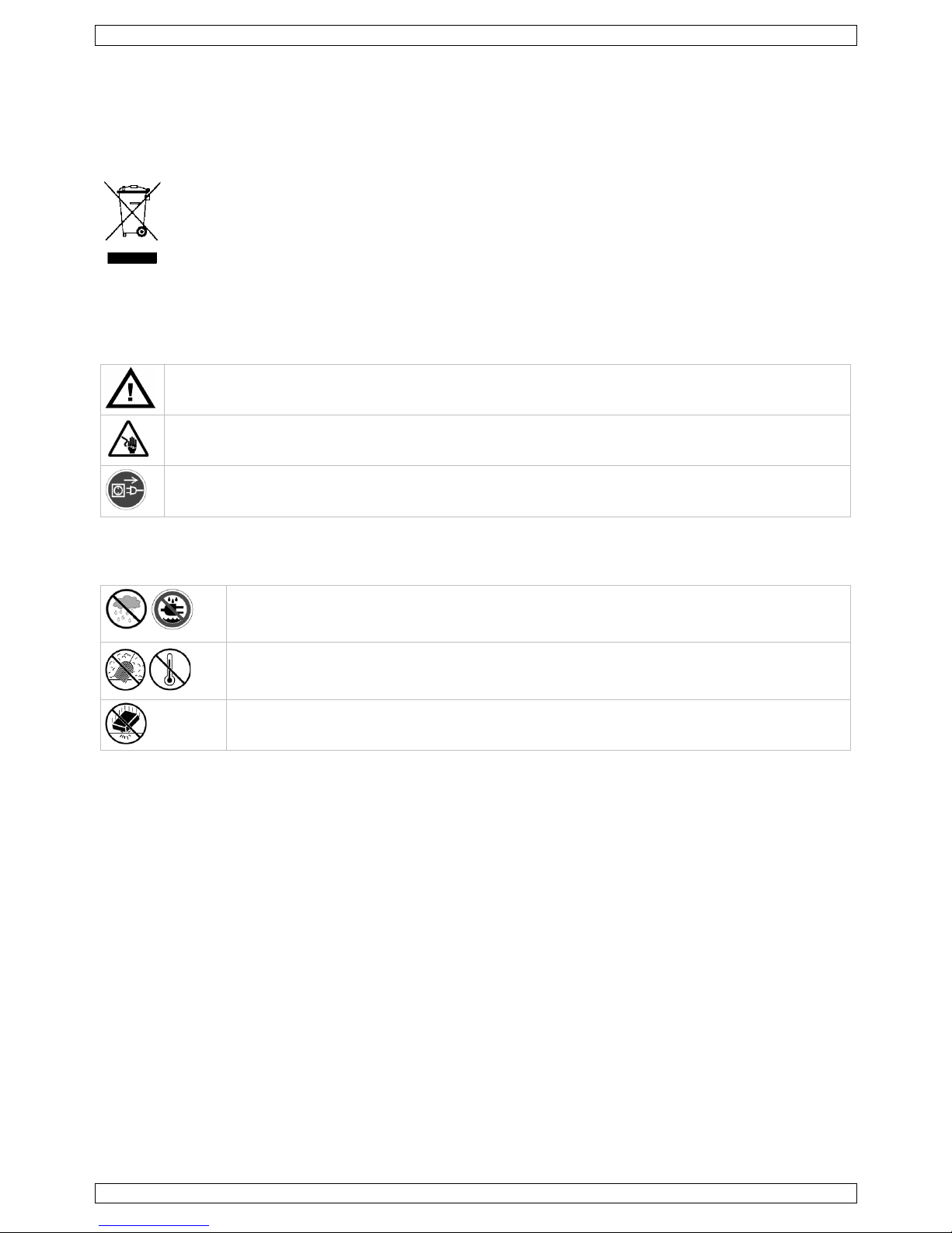
2. Safety Instruction s
Keep this devi ce away from children and unauthorized users.
Risk of electroshock when opening the cover. Touching live wires can cause life-threatening
electroshocks.
Always disconnect mains power when device not in use or when servicing or maintenance activities
are performed. Handle the pow er co rd by the plu g only.
3. General Guidelines
Refer to the Velleman ® Service and Qualit y Wa rranty on the last pages of this man u al.
Indoor use only. Keep this device away from rain, moisture, splashing and
dripp in g liqu ids .
Never put o bj ects filled with liquid on top of or close to the device.
Keep this device away fro m dust and extreme temperatures. Make sure the ventilation
openings are clear at all times. For sufficient air circulation, leave at least 1" (±2.5 cm) in
front of the openings.
Protect this device from shock s and abu s e. Avoid b rute force when oper ating the device.
• Familiarise yourself with the functions of the device before actually using i t.
• All modifications of the device are forbidden fo r safety reasons. Damage caused by user modifications to
the devi ce is not co vered by the warran ty.
• Only use the device for its intended purpose. Using the device in an unauthorised way will void the
warranty.
• Damage caused by disregard of cer tain guidelines in this manual is not covered by the warranty and the
deal er will n ot accept responsibility for any ensuing defec ts or problems .
• Keep this manual fo r fu tur e referen c e.
• DO NOT use this product to violate privacy laws or perform other illegal activities.
4. Features
• full high definition recording
• recording throughput: 16 channels
• 1920 x 1080 pixels (full HD): 480 IPS, 120 Mbps
• mobile surveillance via free EagleEyes software on iPhone, iPad, and Android
• mobil e phone connection vi a GPRS, 3G data or Wi-Fi
• GUI (Graphical User Interface) display and USB mouse
• high compatibility and off site backup:
o compatible with all major IP cameras that are ONVIF ce r tified
o eSATA interface to conn e c t a dis k ar r a y (up to 4-bay dis k ar r ay with R A ID 0 and 1)
o works with free Central Management System (CMS) softwar e fo r offsi te b ac k u p
NVR4
V. 01 – 14/04/2014 4 ©Velle ma n nv
• local an d r emote control compl etely independent
• HDMI video output resolution up to 1080p
• automati c in teg r ated Dynamic Domain Name Service (D DNS): free service
• USB mouse: incl.
• IR remote cont rol: incl.
Optional hardware
• hard disk: HD500GB/S, HD1TB/S, HD2TB/S
• monitor: MONSCA9
• HDMI cable: PAC400Tx series and PAC400Gx series
• compatible IP cameras: CAMIP16, CAMIP17, CAMIP18, CAMIP19
• router: EM4544, EM4543, EM4571, PCRT1
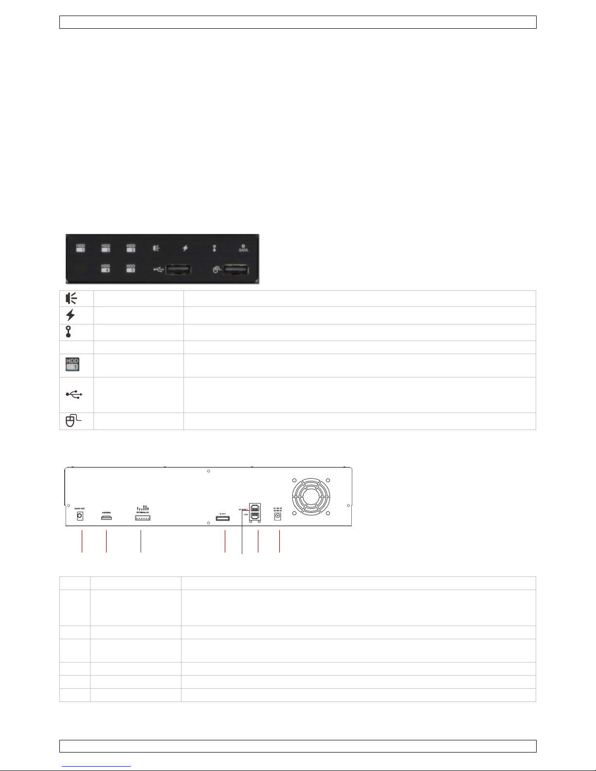
5. Overview
Fr on t pa nel
alarm LED indicator: an alarm event occurs
wan LED indicator: the NVR is co nnected to internet
lan LED indicator: the NVR is co nnected to the LAN
SATA
LED indicator: SATA hard disk is active
HDD1 to HDD5
LED indicator: up to 5 hard disks ar e installed in the NVR and connected well
(3 HDD wit h qui ck-loc k inst allation )
US B por t
Insert a co mpatible USB flash drive for video backup.
Note: Fo r the li s t of co mp atible USB flash drives, r efer to the full manual on the
CD-ROM.
mou se po rt Insert a mouse (included).
Back panel
1
AUDI O OUT
Connect to an amplifier audio line-in.
2
HDMI video output
port
Con nect to a moni tor that supports high-defi nition video output (HDMI port ).
Note: Use an appr opriate adapter (not incl.) to connect a monitor with VGA o r
composite connectors.
3
External I/O
RS 485 port
4 eSATA
This po r t is used to conn ec t a storag e devic e suppo r ting eSATA interface; for
in stance, an external disk array.
5 WAN Connect to internet via an 8P8C (RJ45) network cable
6
LAN
Connect to local IP cameras via an 8P8C (RJ45 ) network cable.
7 DC 19V IN Connect to the power supply adapter (incl.).
1 2 3 4 5 6 7

NVR4
V. 01 – 14/04/2014 5 ©Velle ma n nv
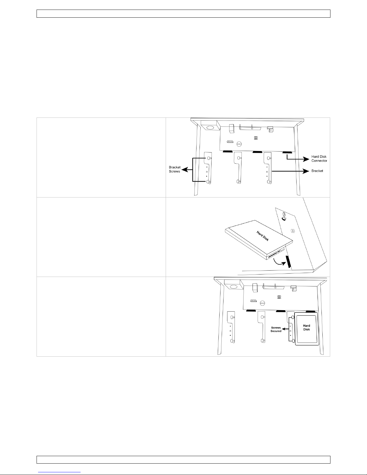
6. Installing a ha r d disk drive
Preparation
• Make sure to unplug the device from the mains bef o re servicing and do not touch any electronic circuitry to
avoid electr osta t ic discharge .
• Obtain a sui table hard disk (not included), type SATA. The hard disk must be formatted.
• You can install up to 3 with the qui ck lock system (shown below).
• If you want to use a green hard di s k, use only a dis k d esig ned especially for sur veil lance to ensure the
device works properly.
1. Loos en th e screws an d remo ve the top
cover.
2. Locate the hard disk connector and b racket
in the device. The screws are attached to
the br acket.
3. With the PCB sid e facing down, align the
hard disk with the har d disk pow e r & sata
port, and insert the hard disk.
4. Fasten the hard disk to the bracket with the
built-in screws.
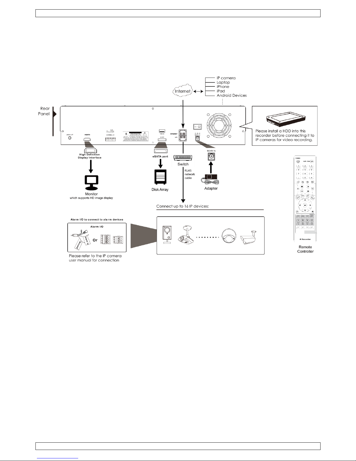
7. Connection Diagram
• You can connect up to 16 IP cameras.
• To e nsure that auto ma tic confi guratio n works well , connect and switch on the IP cameras first. Only then
switch on the NVR.
• This device requires a minimum of network installation knowledge.
• To access the NVR remotely with your mobile d evic e or l ap top, you need to connec t the NVR recorder to the
Internet. F or details, pl eas e refer to the setup manual on
www.surveillance-download.com/user/network_setup/network_setup_recorder.pdf.
Connecting the IP camera (plug and play)
Refer to the ill ustrati on on p a ge 2 for the s e tu p diagram.
1. Connect the camera to a hub/switch.
2. Wait until the camer a is configured automatically and the images appear on the monitor.
NVR4
V. 01 – 14/04/2014 6 ©Velle ma n nv
Notes
The rec order will automaticall y confi g u r e the IP addr es s of a camera connected by LAN if:
• The co n n e c ted IP camera is ou r brand’s IP camera.
• The default I P co nfiguration method of the camera i s s et to DHCP (def ault setti n g).
• The camera is power ed on b efo r e the r eco rder is powered on.
8. Information and Menus on the Screen
Key lock / unlock
To lock or unlock NVR local operation, cli c k (lock) or ( unlock) o n the N VR status panel. Wh en yo u
unl ock NV R local ope r a tion, the system asks you to enter a user name and password.
Note: The def aul t user name and password are "admin". Differen t u s er types have different access righ ts to
NVR functi ons. For details, refer to the full manual on the CD-ROM.
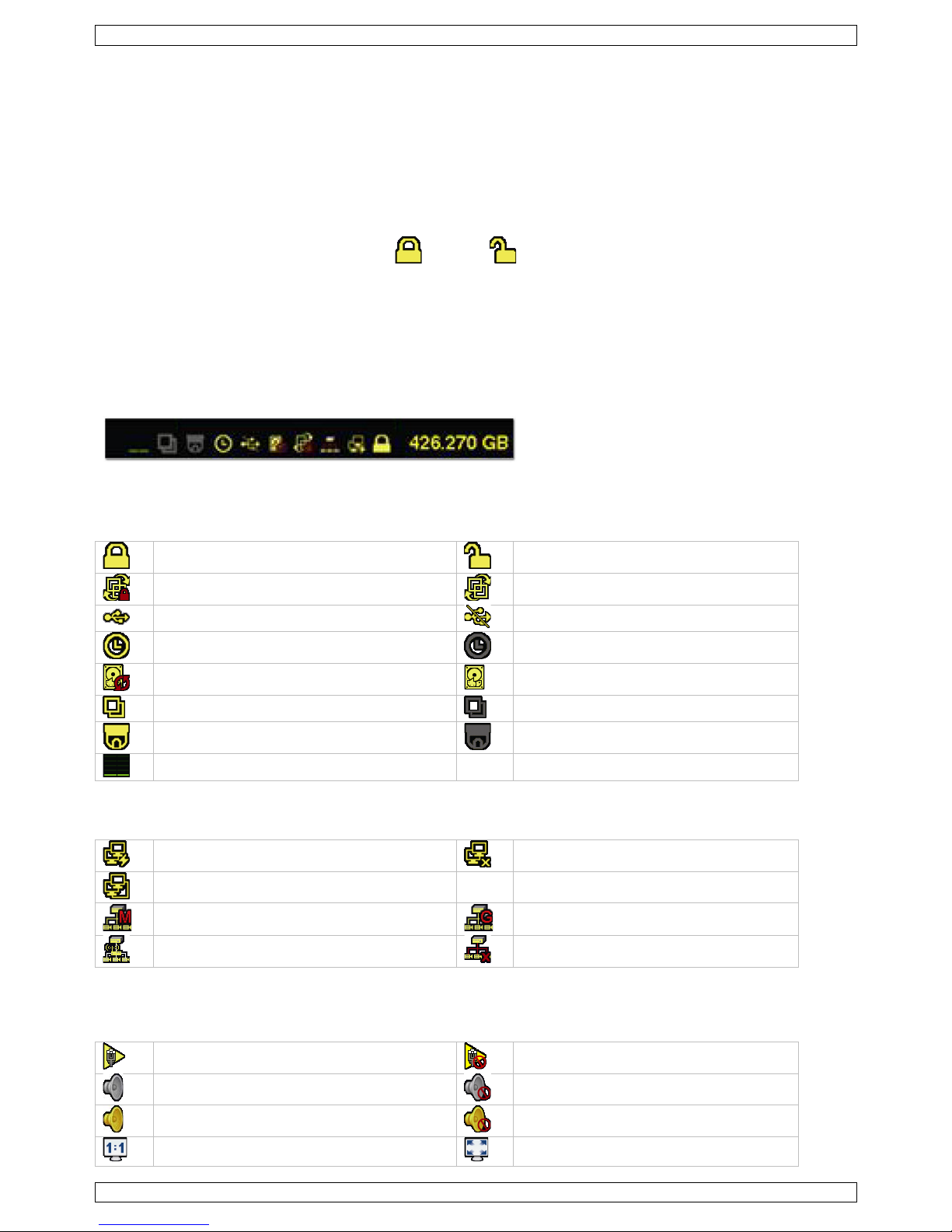
8.2 NVR and Network Status Icons
The status icons for NVR and network are displayed on the upper right corner of the sc reen (next to the
available har d di sk spac e).
The icons displayed may vary depending on your situation or configuration.
The pos sible icons are:
NV R status Icons
key lock
key unlock
channel lock
channel unlock
USB fl as h dri ve / devi c e co n n ec ted
no USB device co nnected
timer recording on
timer recording off
overw ri te on
overw ri te off
sequenc e mode on
sequenc e mode of f
PTZ mode on
PTZ mode off
CPU load
Network Status Icons
(WAN) internet connected
(WAN) internet disconnected
(WAN) local connec tio n
(LAN) auto mode – Mbit/s
(LAN) auto mode – Gbit/s
(LAN ) DH C P / static IP mode
(LAN) camera disconnected
Cha nnel Status
The Channel Status icons are displayed on each channel on the screen. The possible icon s are:
auto search on
auto search off
live a u dio on
audi o off
audio playback on
audio playback off
original size
fit to sc r een
NVR4
V. 01 – 14/04/2014 7 ©Velle ma n nv
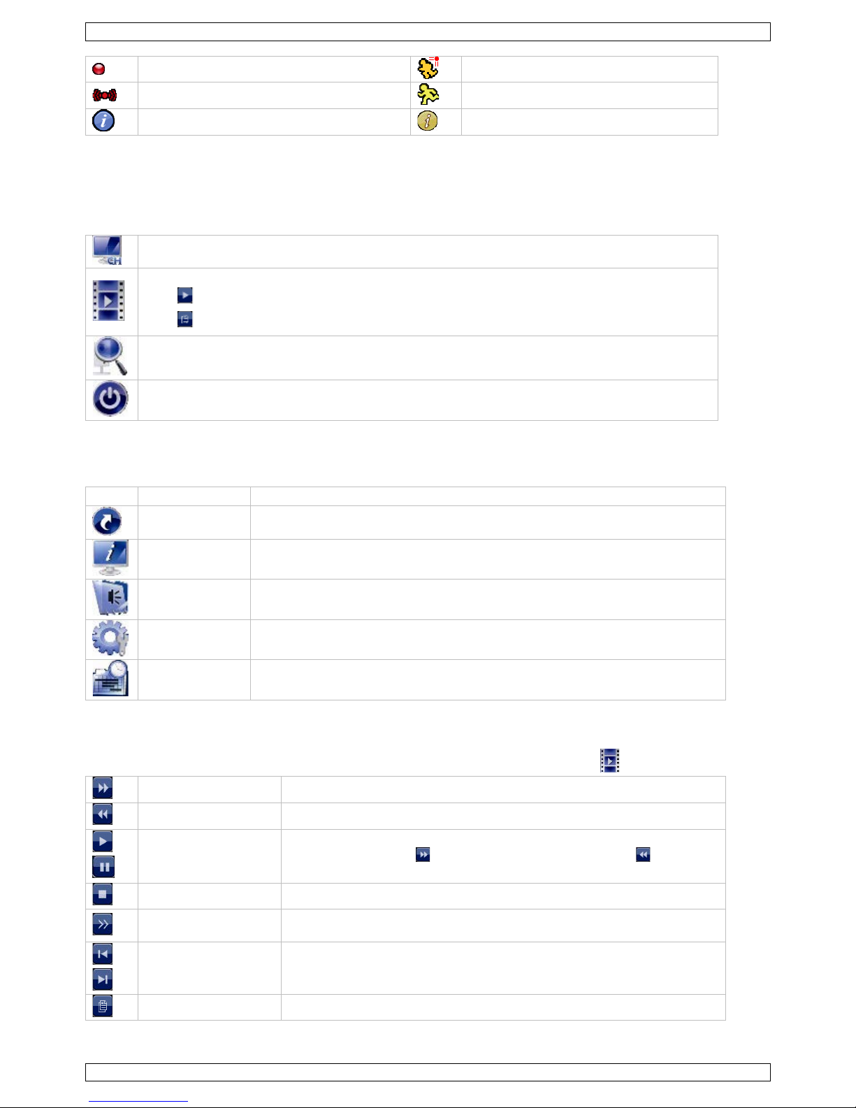
recording
human detection event
alarm event
motion even t
live info r mation
playback information
Quick Operation Menu
To access the Q uick Operatio n menu, point the mouse to the arrow mark on the left o f the screen. It contains
the following icons:
Click to show the channel switch panel and select the channel you want.
Click to display the playback control panel. In the control panel:
Click to play the lates t r e c orded video clip
Click to open the search list.
Click to open the IP search window and check the connection status of each channel.
Click to show the power-off p anel to stop or reboot the sy stem.
Ma in m enu
To access the main menu, right-click anywhere on th e screen . Right-click again to hide the menu.
Icon Label Con tains settings for
Quick start
Channel Title, Event Status, Date Display, Mous e
Sensitivity, Record Config.
System Account, To ols, System Info, Backup Schedule, Online, Regular Report
Event
information
Quick Search, Event Search, HDD Info, Event Log
Advanced config
Connection, Camera, Detection, Al ert, Network, Display, Record, Notify,
Multicasting
Schedule
setting
Event Timer, Record Timer
Playback panel
To acces s the playback panel, open the Quick Operation menu (see above) and click .
fast forward Click to fast forward at 4 t o 32 times normal speed.
fast rewind Click to fast rewin d at 4 to 32 times normal speed.
play/pause
Clic k to pl ay the l atest recorded video clip. Click agai n to paus e .
In pause mode, click once to go one frame forward, or to go one
frame backward.
stop Click to stop th e vi deo playback .
slow playback
Click once to play at 1/4 no r mal speed, click twice for 1/8 normal
speed.
previous/next hour
Click to jump to the n e x t/previous one-hour time interval (fo r example,
11:00 to 12:00 or 14 :00 to 15:00) and s tar t playing the earli est vi deo
clip recorded during this hour.
quick search Click to enter the qui ck search menu .

NVR4
V. 01 – 14/04/2014 8 ©Velle ma n nv
9. Confi gurati on of ca mera on LAN Port plug and play
Note: This configuration method applies to ETS c amer as.
Automatic Configuration
The NVR will automatically configure the IP address of an ETS camera connected by LAN if:
• The default IP configuratio n method of the camera i s DHCP.
• The camera is power ed on before the NVR is powered on.
If not , you can config u r e the I P addres s of your c amera manual ly as described further below.
Manual Configuration
If the NV R do es not con figure the IP address of your c amer a au tomaticall y as desc ri bed above, the d e fault IP
configuration method of your IP camera may n ot be set to DHCP. To solve this, r econ fig u r e th e c ame ra’ s IP
address to 10.1.1.xx (xx ranges from 11 to 253) , in the s ame network segment as the NVR.
1. In the qui c k op er ation panel, click . You’ll see the list of ever y co nn ected IP camera with its connec tion
status and MAC address .
2. Select an IP add ress that is not u se d (UNUSED), and click SETUP.
3. Select STAT I C in NETWO RK TYPE, and chang e the I P addres s to 10.1.1.xx (xx ranges fr om 11 to 253).
4. Click APPLY and EXIT to save your changes.
5. Wait until th e NVR detects the IP c amer a an d displays images.
Configuring a remote internet camera
Vi a i n te r n e t you can reco r d vid e o images from an IP camera in a remo te location.
1. Make sure that the IP camera i s accessibl e ou tside its LAN network via a dynamic do main name (for
example ip_office.ddns.eagleeyes.tw).
2. In the main menu, click (ADVANCED CO NFIG) and select CONNE CTION.
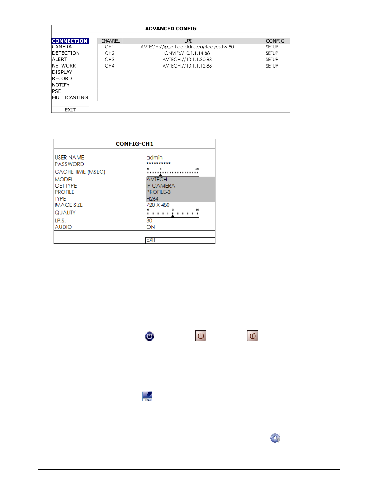
NVR4
V. 01 – 14/04/2014 9 ©Velle ma n nv
3. To assign a channel to a remote IP camera, click URI to enter the address of the camera and its port
number.
4. Click SETUP to enter the access info r mation of th e camera.
5. Enter the user name (USER NAME) and password (PASSWORD) to access the IP camera.
6. Click GET TYPE to detect the camera and make sure the access information is correct.
7. Select the image si z e (IMAGE SIZE), ima ge qua lit y (QUALITY), and images per second (I.P.S.).
Note: The available options depend on the camera you want to connect.
8. Click GET TYPE to detect the camera and make sure the access information is correct.
9. Optional: for a cam e ra with au dio recording, set AUDI O to ON or OFF.
10. Quick Operation
Switching off and Rebootin g
To po we r of f or re boot the NV R :
• In the Qu ick Opera ti on menu, click and then click (power of f) or (reboot).
Viewing a Channel in Full-S creen Mode
Y ou can vie w a channe l in full screen mode as follows:
• Click direc tly o n the channel image to see that channel in full screen mod e.
Double-click the image to restore the previous overview.
- or -
1. In the qui c k op er ation panel, click .
2. On the control panel that appears, select the channel you want to display in full screen mode.
3. Click the button 4 – 6 - 9 - 12 or 16 to select another view.
Playing Recorded Video Clips
1. Make sure that manual and/o r event recording is enabled: in the main menu, click (ADVANCED
CONFIG) and select RECORD to ch eck or adjust the settings .
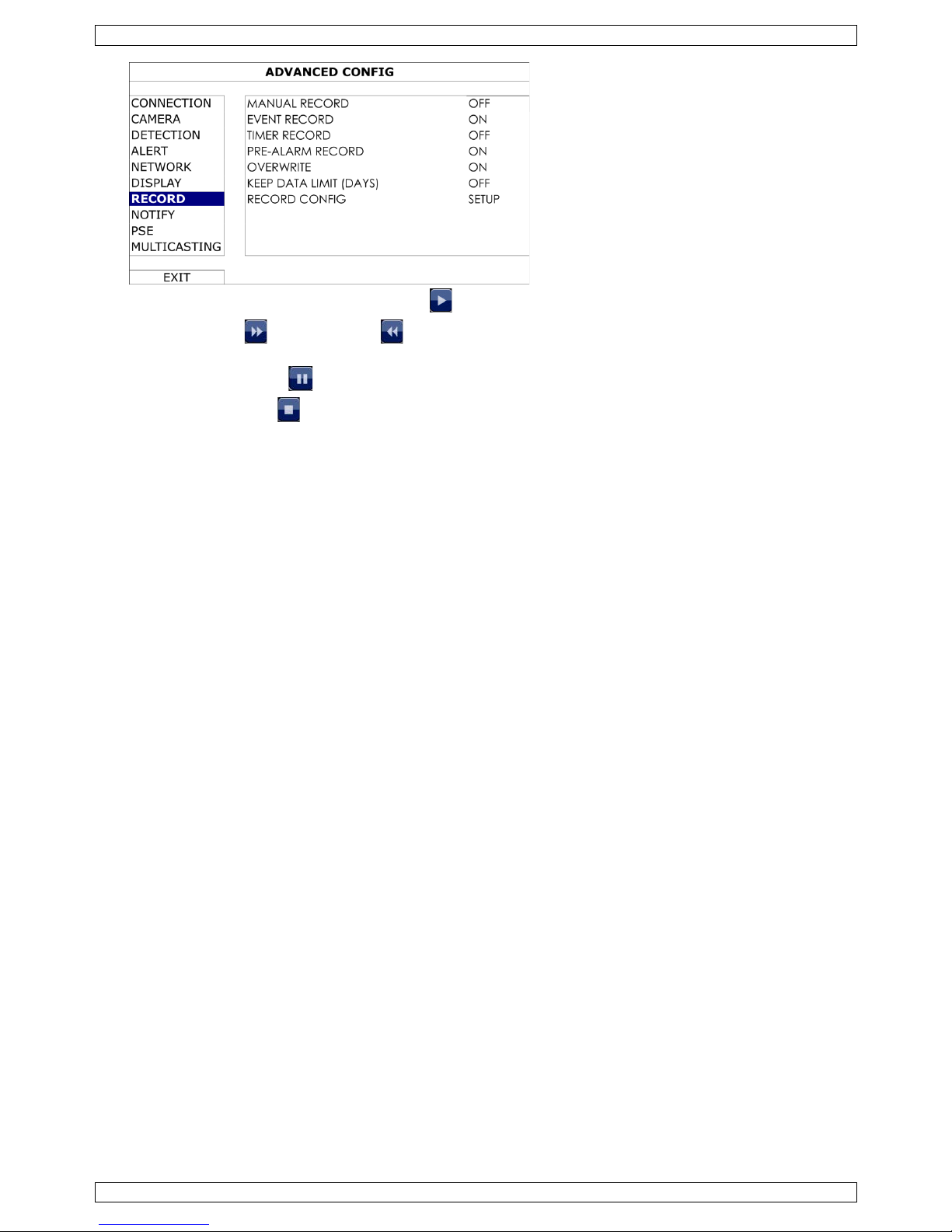
NVR4
V. 01 – 14/04/2014 10 ©Velleman nv
2. In the playback panel, press the play button . The recorded files are shown.
3. The fast forward and fast rewind buttons increa se /decrease the pl ayb ac k speed. Pres s the button
repeatedly to increase/decrease the speed to 4x, 8x, 16x, or 32x (max.).
4. Press the pause button to pause playback.
5. Press the stop button to stop pl a yback and return to live monitoring.
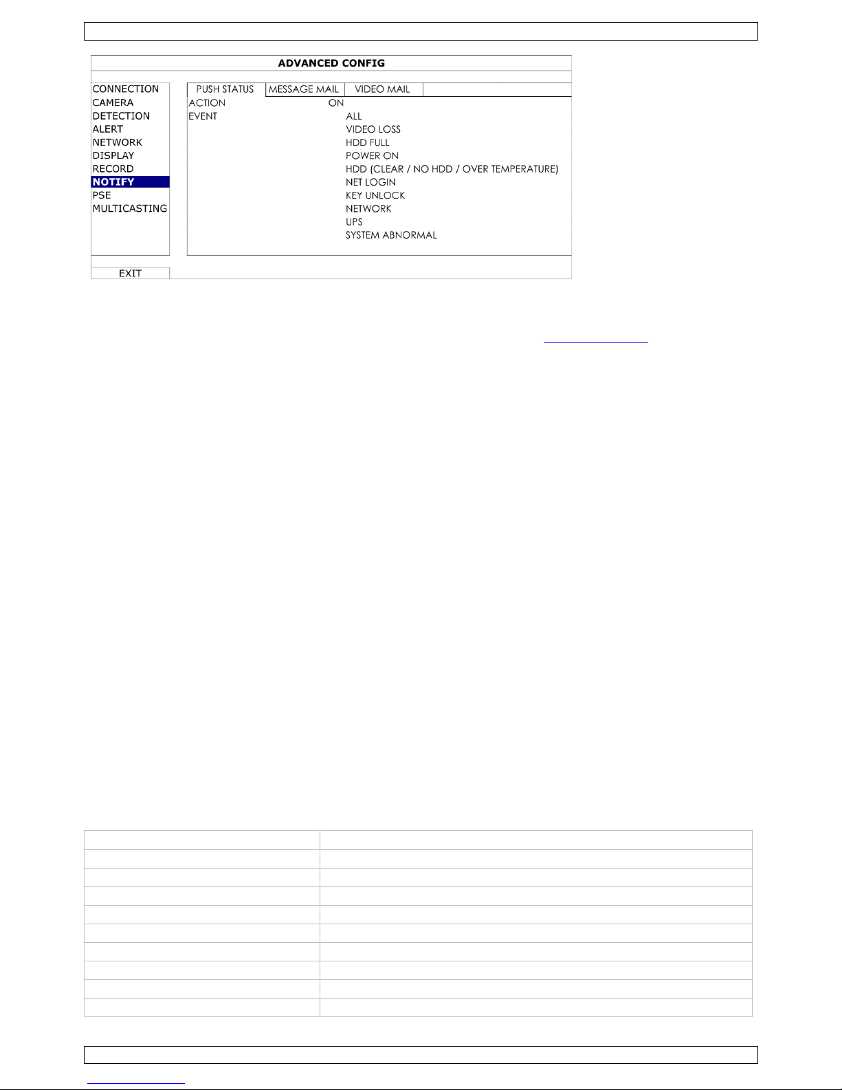
11. Push Status
The Push Status functions send s notifications about events to the EagleEyes app on your mobile device. You
can select what events you want to be notified about.
Prerequisites
Before using this function, check the foll owing:
• You have iPhone, iPad, or Android™ mobile phone or tablet.
• You have subscrib ed to and you can access mobile internet services for your mobile phone.
• The mobile ap p, EagleEyes, is installed in your mob ile device.
For details, see the section "Installing the EagleEyes" app below.
Configuring the WAN port
1. Make sure the NV R is prop erl y co n n ec ted to a sw itc h with a RJ45 networ k cable.
2. On the NVR, select ADV ANCED CONFIG > NETWORK > WAN.
Configuring Push Status
Before configuring push status, make sure that:
• The NVR i s set up as descri b ed above.
• The NVR i s conn ec ted to the intern et.
On the NVR
1. Select ADV ANCED CONFIG > NOTIFY > PUSH ST ATUS.
2. Set ACTION to ON .
3. Select the system event or events you want to get no ti fied about on your mobile dev i ce.
NVR4
V. 01 – 14/04/2014 11 ©Velleman nv
On your mobile device
• Enable Notifications in EagleEyes on your mobil e d evi c e.
• For detai l s abou t E agl eE y es , r efer to the EagleEyes Installation Guide on www.velleman.eu
or visit
www.eagleeyescctv.com.
Testing
1. Try to trigger an al arm event.
For example, if you set VIDEO LOSS as an event, dis con n ect the video to see if you get a push status
notification.
11.2 Installing the EagleEyes app
Prerequisites
Befo r e in s talling EagleEyes to your mobil e phone for remote surveillance, make sure you have checked th e
following:
• You have subscrib ed to and you can access mobile internet services for yo ur mobile phone.
• Note: You might be charg ed fo r internet ac c es s via wi r eless or 3G netwo r ks. For the i n tern et acc ess rate
details, check with your local network operator or service provider.
• You have noted down the IP address, port number, user name and password used to access your network
camera from the intern et.
Wher e to dow n load
1. Connect to www.eagleeyescctv. com from your mobile devic e, and sign in .
Do not try to download EagleEyes from yo ur computer.
o Fo r Android, s elect the download link from the website to start downloading.
o For i Pho n e an d iPad , two ve rsions of EagleE y es are available: EagleEyesHD Plus (at a fee) , and
EagleEyesHD Lite (free).
2. Select the ver sion you want, and you will be dir ected to th e App S tore to download the application.
3. When the download is completed, EagleEyes will install automatically to the default location or any location
you choose.
12. Technical Specifications
video compression
H.264 / MPEG4 / MJPEG
video input 1 LAN port up to 16 channels with a hub/switch
video output
HDMI output 1920 x 1080 pixels
recor ding m ode manual / timer / motion / alarm
mul ti plex op e r ati on liv e display, record, playb ack, backup and n etwork
au dio I/O:
in put: onl y vi a I P cameras
output: 1 audio output
motion detec ti on area
22 x 18 grid per camera
motion detection sensitivity
10 adjustable variables with precise calculation for motion detection
pre-alarm recording yes

NVR4
V. 01 – 14/04/2014 12 ©Velleman nv
backup device
USB 2.0 backup and network remote backup
hard disk storage
built-in SATA typ e : s upports 3 x HDD , s u pp orted HDD ca pacity to 3 TB
(HD D not in cl.)
external eSata: external hard dis k or dis k array (Linux sys tem
support)
web interface
suppo rts free CMS software (Windows & Mac OS)
all major internet b r owsers via Java, QuickTime and VLC plug-in
(Internet Explorer, Firefox, Safari, Google Chrome)
mobile surveillance – sm art phones - app: iPad, iPod touch, iPhone, Android phone & tablet
- available on www.eagleeyescctv.com
- remote login via all smart phone platforms (Apple, Android,
BlackBerry, Nokia Symbian and Windows Mobile)
mobile surveillance – computer
- CMS (Central M an ag emen t System): remote su r veill an c e to mo ni tor
up to 10 diff er en t IP ad dresses (Windows & Mac OS)
- web brows er : Inter n et Explorer, Firefox, Google Ch rome and Safari
via Java, QuickTime or VLC plug-in
remote alarm noti fication SMS message, e-mail and image u ploading to FTP sites
network connection
sup ports TCP/IP, PPPoE, DHCP and DDNS functi on
power source
19 VDC / 3.42 A (i ncl.)
power consumption 17.5 W (without a hard disk connected)
op e r ating temper atu r e
10 °C to 40 °C
system recovery system auto r ec overy after power reconn ected
dimensions 432 x 90 x 326 mm
Use this device with original accessories only. Velleman nv cannot be held responsible in the event
of da mage o r inj ury resulted f rom (in co rrect) use of this device.
For more info concerning this product and the latest version of this manual, please visit ou r website
www.velleman.eu.
The information in this manual is subject to change without prior notice.
© COPYRIGHT NOTICE
The copyright to this manual is owned by Velleman nv. All worldwide rights reserved.
No p ar t of this manual or may be copied, reprodu c ed , translated or reduced to any electr onic medium or
othe r wise without the p rior written c onsent of th e copyrig h t holder.
NVR4
V. 01 – 14/04/2014 13 ©Velleman nv
KORTE HANDLEIDING
1. Inleiding
Aan alle ingez etenen van d e Eu r o pese Unie
Bel angrijke mi lieu-informatie betre f fende dit produ ct
Di t symbool op het toestel of de verpakking geeft aan d at, als het na zijn levenscycl u s wordt
wegg eworpen, dit toestel schad e kan toebrengen aan het milieu . Gooi di t toestel (en even tuele
batterijen) niet bij het gewon e h ui shoudelijke afval; het moet bij een gespe cialiseerd bedrijf
terechtkomen voor recycl age. U moet dit toestel naar uw verd el er of naar een l okaal recyclagep u n t
breng en. Respecteer de plaatselijke milieuw etg evin g.
He b t u vragen, con tacteer dan de pla atselij ke autoriteiten be treffende de verwijdering.
Dank u voor uw aankoop! Lees deze handleiding gro ndig voor u het toestel in gebruik neemt. Werd h et toestel
besch adigd tijdens het transport, installeer het d an ni et en r aadpleeg uw dealer.
2. Veiligheidsinstructies
Hou d dit toestel buiten het bereik van ki n d er en en onbevoegden.
Elektrocutiegevaar bij het open en van h et to es tel. R aak g een kabels aan die ond er stroom s taan,
om dodeli jke elektroscho kken te vermijden.
Trek de stekker uit het stopcontact vo ordat u het to e stel reinigt of als u het ni et g eb r ui kt. Hou d de
voedi ngskabel altijd vast bij d e s tekker en ni et bij d e kabel.
3. Algemene richtlijnen
Raa dpleeg de Vel leman® service- en kwal iteitsgar antie achteraan deze handleiding.
Geb ruik het to estel enkel bin nenshu is . Bescherm het toestel teg en regen , voc h tig h eid
en opspattend e v loeistoffen. Plaats geen objecten gevuld met vloeistof op of naast het
toestel.
Bescher m di t toestel tegen stof en extreme temperatur en . Z org dat de
verlu chtingsopeningen niet verstopt geraken. Voor voldoende luchtcirculatie, laat een
minimumafstand van 2.5 cm tussen het to estel en el k ander object.
Bescher m tegen schokken. Vermijd brute kracht ti jd en s de bedieni n g.
• Leer eers t d e functies van het toestel kenn en voor u het gaat gebruiken .
• Om veiligheids redenen mag u geen wijzigingen aanbreng en . Sch ad e door wijzi gingen die de gebruiker heeft
aangebrac h t aan h et to es tel valt niet onder de garantie.
• Gebrui k h et toestel enkel waarvoo r het gemaakt i s . De garantie ver valt automatisch bij ong eoorloofd
gebruik.
• De garantie geldt niet voor schade do or het negeren van bepaalde rich tlijnen in deze handl eiding en uw
deal er z al de verantwoo rdelijkheid afwijzen voor defec ten of probl emen die hier rechtstreeks verban d mee
houden.
• Bewaar deze handleiding voor verdere raadpleging.
• Installeer en gebruik deze camera NIET voor illegale praktijken en respecteer ieders privacy.
4. Eigenschappen
• Full HD-opname
• op n amec apaciteit: 16 kanalen
• 1920 x 1080 pixels (Full HD): 480 IPS, 120 Mbp s
• bewaking op afstand via de gratis EagleEyes-software op iPho n e, iPad en A ndroid
• aansluiting met d r aagbaar toes tel vi a GPRS, 3G of wifi
• di splay met gr afische gebruikersinterface (GUI) en USB-muis
• hoge compatibiliteit en off-site back -up:
o co mpatibel met d e v oornaamste IP-camera's die ONVIF-gecertificeerd zijn

NVR4
V. 01 – 14/04/2014 14 ©Velleman nv
o eATA-interface, om een disk-array aan te slui ten (met max. 4-bay voor Raid 0 of Raid 1)
o wer kt me t de gratis CMS-software ( C entr al M anag emen t System) voor off-site back-ups
• lokale controle en controle op afstand, volledig onafhankelijk
• HDMI-uitv oerresol u tie tot 108 0 P
• automati s c h e geïnteg reer de dynamische domein n aamser vice (DDNS): grati s
• USB-muis: meegelev.
• IR-afstand s bediening: meegelev.
Optioneel
• harde schijf: HD500GB/S, HD1TB/S, HD2TB/S
• monitor: MONSCA9
• HDMI-kabel: PAC400Tx-reeks en PAC400G x-reeks
• compatibele IP-camera's: CAMIP16, CAMIP17, CAMIP18, CAMIP19
• router: EM4544, EM4543, EM4571, PCRT1
5. Omschrijving
Frontpaneel
alarm Led-indicator: een alarm doet zich voor
wan Led-indicator: de NVR is verbonden met internet
lan Led-indicator: de NVR is verbon d en met het LAN-netwerk
SATA
Led-indicator: SATA-harde sch ijf is actief
HDD1 n a a r HDD 5
Led-i n dicator: er zijn 5 harde schijven geïns talleerd en correct aangesloten
(3 harde schi jven met quick-lock-installatie)
USB-poort
Sluit een compatibele USB flash drive voor videoback-up aan.
Opmerking: Voor de lijst met compatibele USB flash drives , raadpleeg de
voll e dige handleiding op de CD -ROM.
muispoort Sluit een muis aan (meeg eleverd).
Achterpaneel
1
AUDI O OUT
Verbind met de Audio Line-ingang van een vers terker .
2 HDMI-uitvoerpoort
Sluit aan op een monitor die HDMI voor high-d efi nition v ideo-uitgang ondersteunt .
Opmerking: G eb r ui k een ges chikte adapter (niet meegel ev. ) om een monito r die
VGA of composie t ondersteunt, aan te sluiten.
3 Externe I/ O RS 485-poort
4 eSATA
Deze poort wordt g ebruikt om een opslagapparaat aan te sluiten dat eSATA-
interface ondersteunt; bijv. een extern e d isk-array.
5 WAN Verbind de NVR met internet via een 8P8C-netwerkkabel (RJ45)
6
LAN
Verbind de NVR met lokale IP-camera’s via een 8 P8 C -net werkkabel (RJ45).
7
DC 19V IN Verbind de NVR met de voedingsad apter (meeg elev.).
1 2 3 4 5 6 7
NVR4
V. 01 – 14/04/2014 15 ©Velleman nv
6. Een harde schijf (HDD ) instal leren
Voorbereiding
• Zorg ervoo r dat u het toe stel ontkoppelt van het li chtnet. Raak g een elektronische circuits aan om
elektrische schokken te voo r komen.
• Gebrui k een co mp atib ele harde schijf (ni et meegelev.), type SATA (Seri al Advan c ed Tech n ology
Attachment). F ormatteer eerst de harde s c hijf.
• U kunt tot 3 harde schijven install eren met het quick-lock-systeem (zie onder).
• Indien u een groene harde schijf wilt gebruiken, g ebrui k d an alleen een schi jf die speciaal ontworpen is voor
bewaking om ervoor te zorgen dat het toes tel c orrect functioneert.
1. Schroef de bovenkant los en verwijder het
deksel.
2. Zoek d e co nnector [1] en beugel [2] voo r
de harde s chijf in het toestel. De schroeven
zijn aan de beugel bevestigd.
3. Houd de harde schijf met de printplaat naar
beneden , li jn de harde schijf met de
voedings- en sata-poort uit en plaats de
harde schi jf.
4. Bevesti g de harde schijf aan de beugel met
de ingebo u wd e s chroeven.
7. Aansluitdiagram
• U kun t tot 16 IP-camera’ s aansluiten.
• Sluit eerst de IP-camera's aan en schakel ze in, om er voor te zorgen dat d e automatisch e co nf iguratie
correct func ti oneert. Sc hakel daarna p as de NVR in.
• Di t toestel vereist een basiskenn is van netwerkins tallaties.
• Verb ind de NVR met h e t i n te r n e t om toegang te krijg e n to t de NVR via uw dr aagbaar to estel of lapto p. Voor
meer informatie, raadpl eeg de h an dl ei ding op
www.surveillance-download.com/user/network_setup/network_setup_recorder.pdf.
De IP -camera aansluit en (Plug -and-Play)
Raadpleeg de afbeeldingen op pagina 2 voor het aansluitdiagram.

NVR4
V. 01 – 14/04/2014 16 ©Velleman nv
1. Verbind de camera met een hub/switch .
2. Wacht tot de camera automati sch geco nfi g u r eerd is en de beelden op het sch er m vers chijnen.
Opmerkingen
De NVR configureert het IP-adres van een ETS-camera die verbo n den is via LAN auto matisch als:
• de aanges loten IP-camer a ons merk is.
• de stan d aar d IP-configuratiemethode van de camera D HCP is (standaardinstelling).
• de camera vo or de NVR ingeschakel d is.
8. Informat ie en menu's
Toetsvergrendeling
In het statusmenu, klik op (verg ren delen) o m de bediening van de videorecord er te vergrendelen, of klik
op (o n tg r en d el en ) o m de bedi ening weer vrij te geven. W ann eer u de bedieni n g weer vri jg eeft, moet u een
gebru ikersnaam en wachtwoord ingeven.
Opmerking: De standaard gebruikersnaam en wachtwoord zijn "admin". Verschillende gebruikers hebben
verschi llende toegangsrechten. Raadpl eeg de volledige handleidi ng (beschikbaar op de CD-ROM) voo r meer
informatie.
8.2 NVR- en netwerkstatus
De statuspictogrammen voo r NVR en netwerk worden rech ts bo ven in h et scherm weergegeven (naast d e
beschi k b are r ui mte op de harde schijf).
De weer gegeven pic togr ammen ku n n en afwi jken, afhankelijk v an de toegang s r echten van de gebruik er.
De mogelijke pictogrammen zijn:
NVR-status
toetsvergrendeling
ontgrendeld
kanaal v er grendeld
kanaalver g r en d el ing ontgrendeld
USB flash drive / appar aat aan gesloten
geen US B-apparaat aangesloten
timer-opname ingesc h akeld
timer-opname uitg esch akeld
functie overschrijven ingeschak eld
functie overschrijven uitgeschakeld
sequentiemodus ingeschak el d
sequen tiemodus uitges chakeld
PTZ-m odu s inge scha ke ld
PTZ-modus uitgeschakel d
CPU-belasting
Netwerkstatus
(WAN) met internet verbond en
(WAN) niet met i n tern et verb on d en
(WAN) lokale verbinding
(LAN) auto-modus - Mbit/s
(LAN) auto-modus - Gbit/s
(LAN ) DH C P / statische IP-modus
(LAN) camera niet aang esloten
Kanaalstatus
De pic togr ammen wo r den op elk kanaal op het scherm weergeg even . De mog elijke pictogrammen zijn :

NVR4
V. 01 – 14/04/2014 17 ©Velleman nv
automat isch zoeken ingeschakeld
automatisch zoeken uitgeschakeld
live-geluid ingeschakeld
gel ui d uitg es c h akel d
gelu id afspe len in geschakeld
ge luid af s p elen u itgescha k eld
originele grootte
passend op scherm
op n ame ac tief
menselijke aanwezigheid wor dt
gedetecteerd
een alarm do et zich voor
be weging wordt gedetecteerd
live-beelden
afspelen van opgenomen beeld en
Snelmenubalk
Beweeg d e pijl naar links in het scherm, om de snel menubalk weer te geven. Deze geeft de volg en d e
pi c tog rammen weer:
Klik om het kanaalkeuzevenster weer te geven en het gewenste kanaal te selec teren .
Klik om het af s peelp aneel weer te g even . I n het controlepaneel:
Klik op om de laa tste vid eo-o p n ame af te spelen.
Klik op om de zoeklij s t te open en .
Klik om het IP-zoekven s ter te openen en de verbindingsstatus van elk kanaal te controleren.
Klik om het ui ts c h akelmenu weer te geven en het apparaat uit te schakelen of opnieuw op te
starten.
Hoofdmenu
Klik met d e rechtermuisknop eend er waar op h et scher m, om het hoof d men u te open en . Kli k no g maals met de
rechtermuisknop om het menu te verber gen.
Pictogram Naam Opties
Quick start
Channel Title, Event Status, Date Display, Mous e Sensitivity, Record
Config.
System Account, To ols, System Info, Backup Schedule, Online, Regular Report
Event
information
Quick Search, Event Search, HDD Info, Event Log
Advanced
config
Connection, Camera, Detection, Al ert, Network, Display, Reco rd, Notify,
Multicasting
Schedule
setting
Event Timer, Record Timer
Weergavemenu
Open d e snelmenu b alk (zie boven), om het weergavemenu te openen en klik op .
snel vooruit
Klik om vers n el d vooruit af te spelen aan 4 tot 32 keer de normal e
snelheid.
snel achteruit
Klik om vers n el d ac h terui t af te spel en aan 4 tot 32 keer d e nor male
snelheid.
afspelen/pauze
Kl ik om de laat s t e v id eo-opname af te spelen. Klik opni euw om te
onderbreken.
In pauz emodus, klik één keer op om één beel dj e vooruit te springen
of kl ik op om één beel dje ac h teru it te gaan.
 Loading...