

Velleman NVR1 Quick Installation Manual
N
-EA
AENEA
-
UBEGUGUSC
N
Y
W
Y
Y
O
O
S
N
I
N
I
V
A
E
O
L
T
R
C
E
E
N
P
E
R
U
D
N
O
6
A
E
3
3233343
–
U
N
D
D
K
I
O
N
A
I
VR1
6
CHAN
GLE E
H
D NET
E
GLE E
REGIS
GLE E
G
RABAD
H
DMI -
6
KANAL
O
NVIF -
EL HD
ES
ERK V
ES
TREUR
ES
R DE
NVIF -
HOCH
EAGLE
ETWO
DEORE
VIDÉO
DEO E
EAGLE
UFLÖS
YES
K VID
ORDE
RÉSEA
N RED
EYES
NDER
O REC
MET 6
HD À
E ALT
ETZW
RDER
KANAL
CANA
DEFI
RK-VI
HDMI
EN – H
X - HD
ICIÓN
EORE
– ONV
MI –
MI - O
DE 6 C
ORDER
F –
NVIF –
VIF -
NALES
- HDM
-
-
Q
ICK IN
KNOPTE
IDE D’I
A RÁPI
HNELLE
TALLATI
INSTAL
STALLA
DA
NSTIEG
N GUID
ATIEHA
ION RA
DLEIDIN
IDE
G 1

NVR1
V. 01 – 23/03/2012 2 ©Velleman nv
.
oIm
e
.3.
.
u
n
n
m
s
p
k
t
p
a
e
e
a
m
u
e
m
p
r
o
E
t
h
n
t
a
n
e
n
t
s
c
H
i
S
r
p
h
g
f
e
r
s
r
f
d
n
d
d
a
i
n
n
t
r
c
a
o
w
d
f
w
g
i
w
e
e
y
t
i
h
E
S
s
t
o
.
e
r
d
e
e
W
e
q
s
d
o
U
m
r
S
t
c
t
o
e
o
c
e
u
u
o
f
o
e
e
a
e
m
t
r
A
u
v
r
o
r
w
g
o
a
a
e
s
a
o
m
g
p
A
d
b
u
u
r
m
a
e
a
n
b
s
t
w
t
a
d
e
±
t
i
n
n
n
l
1
Introd
T
all reside
portant e
Th
ank you for
th
device wa
2
Safety
This
har
shou
distri
If in
Kee
Ris
elec
ction
ts of the
vironmen
symbol on t
the enviro
ld be taken
butor or to
doubt, co
choosing V
damaged i
Instruc
this device
of electro
roshocks.
Qu
uropean U
al informa
e device o
ment. Do n
o a speciali
local recy
tact your l
lleman! Ple
transit, d
ions
away from
hock when
ick In
ion
ion about
the packag
ot dispose
zed compan
ling service
ocal waste
se read th
n't install o
children an
opening th
NVR1
tallat
his produ
e indicates
f the unit (
y for recycli
Respect th
disposal a
manual th
use it and
unauthoriz
cover. To
ion G
t
hat disposa
r batteries)
ng. This de
local envi
uthorities.
roughly bef
ontact you
d users.
ching live
ide
l of the devi
as unsorte
ice should
onmental r
re bringing
dealer.
ires can ca
ce after its l
municipal
e returned
les.
this device
se life-thre
ifecycle cou
aste; it
o your
into service
tening
d
. If
Gener
Re
fer to the V
•
Familiaris
All modific
•
the device
Only use t
•
warranty.
Damage c
•
dealer will
Keep this
•
DO NOT
•
Alwa
are
ys disconne
erformed.
l Guidel
lleman®
Indoo
Never
Keep t
openin
front o
Protect
yourself wi
ations of th
is not cove
he device fo
used by di
not accept
anual for
se this pro
t mains po
andle the p
nes
ervice an
use only.
ut objects
is device a
s are clear
the openin
this device
th the funct
device are
ed by the
r its intend
regard of c
esponsibilit
uture refere
uct to viola
er when d
ower cord b
Quality
Keep this d
illed with li
ay from du
at all times.
s.
from shock
ons of the
forbidden f
arranty.
d purpose.
rtain guidel
for any en
nce.
e privacy la
vice not in
y the plug
arranty on
vice away
uid on top
st and extr
For sufficie
and abuse.
evice befor
r safety re
sing the d
ines in this
suing defec
ws or perfo
se or when
nly.
the last pa
rom rain, m
f or close t
me temper
nt air circul
Avoid brut
actually u
sons. Dam
vice in an u
anual is n
s or proble
m other ille
servicing o
es of this
oisture, spl
the device.
tures. Mak
tion, leave
force whe
ing it.
ge caused
nauthorised
t covered b
s.
al activitie
maintenan
anual.
shing and
sure the v
t least 1” (
operating
y user mod
way will vo
y the warra
.
ce activities
ripping liqui
ntilation
2.5 cm) in
he device.
fications to
id the
ty and the
ds.
4
Featur
•
high defini
•
6 channel
o real-ti
o smart
to 2M
•
mobile su
•
mobile ph
GUI (Grap
•
V.
01 – 23/03/2
s
tion recordi
video recor
e mode: 3
event recor
ixel
veillance vi
ne connect
hical User I
012
g
ing:
CH x 1.3Mp
mode (wit
free Eagle
on via GPR
terface) dis
xel (25ips)
ETS IP ca
yes softwa
, 3G data o
play and U
+ 3CH x VG
era): 6CH
e on iPhone
r wifi
B mouse
3
(25ips)
x VGA (25i
, iPad and
s) + event
ndroid
rigger chan
el up
©Vellema
nv
NVR1
• high compatibility and offsite backup:
o compatible with all major IP cameras that are ONVIF certified
o added NAS function to back up all kind of IP cameras on the internet
o works with free Central Management System (CMS) software for offsite backup
• local and remote control completely independent
• HDMI video output resolution up to 1080P
• optional hard disk: HD500GB/S, HD1TB/S
• USB mouse: GE31010826101, GE31011039100, GE31030414100
• compatible with: CAMIP9, CAMIP11, CAMIP12, CAMIP13
• optional router: EM4542, EM4553, EM4570, PCRT1.
5. Overview
Refer to the illustrations on page 2 of this manual.
Front panel
1
POWER
2
ALARM
3
WAN
4
LAN
5 RECORD LED indicator: recording is on
6
USB port
7 HDD1/HDD2 LED indicator: up to two hard disks are installed in the NVR and connected well
8
mouse port
Back panel
9 AUDIO OUT Connect to an amplifier audio line-in.
10 WAN Connect to internet via an 8P8C (RJ45) network cable
HDMI video output
11
port
12 LAN Connect to local IP cameras via an 8P8C (RJ45) network cable.
13 DC 19V IN Connect to the power supply adapter (incl.).
14 power switch Switch the NVR on (—) or off (O).
LED indicator: the NVR is switched on
LED indicator: an alarm event occurs
LED indicator: the NVR is connected to internet
LED indicator: the NVR is connected to the LAN
Insert a compatible USB flash drive for video backup.
Note: For the list of compatible USB flash drives, refer to the full manual on the
CD-ROM.
Insert a compatible mouse.
Connect to a monitor that supports high-definition video output (HDMI port).
Note: Use an appropriate adapter (not incl.) to connect a monitor with VGA or
composite connectors.
6. Installing the Hard Disk Drive (HDD)
1. Obtain a suitable HDD (not incl.), type SATA (Serial Advanced Technology Attachment). The HDD must be
formatted.
2. Make sure to unplug the device from the mains before servicing and do not touch any electronic circuitry
to avoid electrostatic discharge.
3. Loosen the screws and remove the top cover.
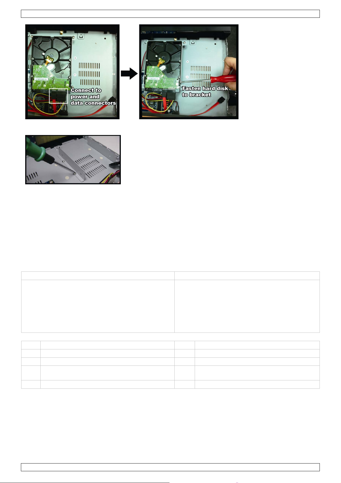
4. Find the hark disk bracket in the NVR, and place the compatible hark disk in the bracket.
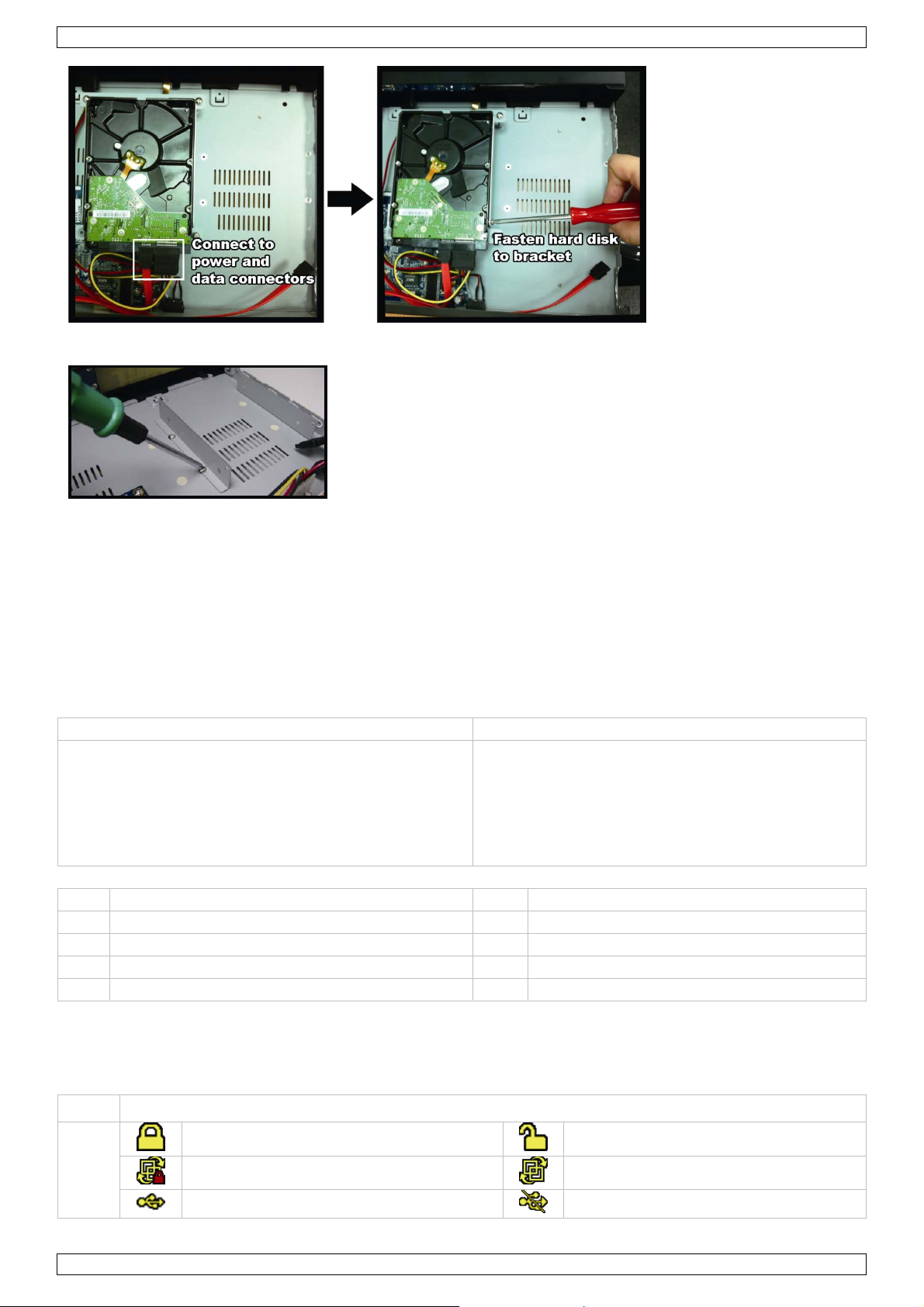
5. With the PCB side facing up, connect the hard disk to the power connector and the data connector.
6. Fasten the hard disk with the supplied screws, two for each side.
V. 01 – 23/03/2012 4 ©Velleman nv
NVR1
7. To install a second hard disk, find the supplied hard disk brackets in the package, and fix them to the NVR
base.
8. With the PCB side facing up, connect the hard disk to the power connector and data connector.
9. Place the hard disk in the brackets and fasten it with the supplied screws, two for each side.
10. Replace the top cover and fasten the screws.
7. Connection Diagram
Note: To ensure that automatic configuration works well, connect and switch on the IP cameras first. Only then
switch on the NVR.
You can connect up to 6 IP cameras.
Refer to the illustrations on page 2 of this manual.
A B
Remote connection: use this method for Push
Video IP cameras and IP cameras connected via
the internet.
1. Enter the IP address and the access information in
the NVR.
2. Wait until you see the images on the monitor.
C Push Video camera H router
D internet camera I mouse
E 8P8C (RJ45) network cable J NVR back panel
F modem K moni tor supporting high-definition video
G hub/switch L 19VDC power supply adapter
Local connection: use this method for ETS
cameras.
1. Connect the camera to a hub/switch.
2. Wait until the camera is configured automatically
and the images appear on the monitor.
8. Information and Panels on the Monitor
Refer to the illustrations on page 2 of this manual.
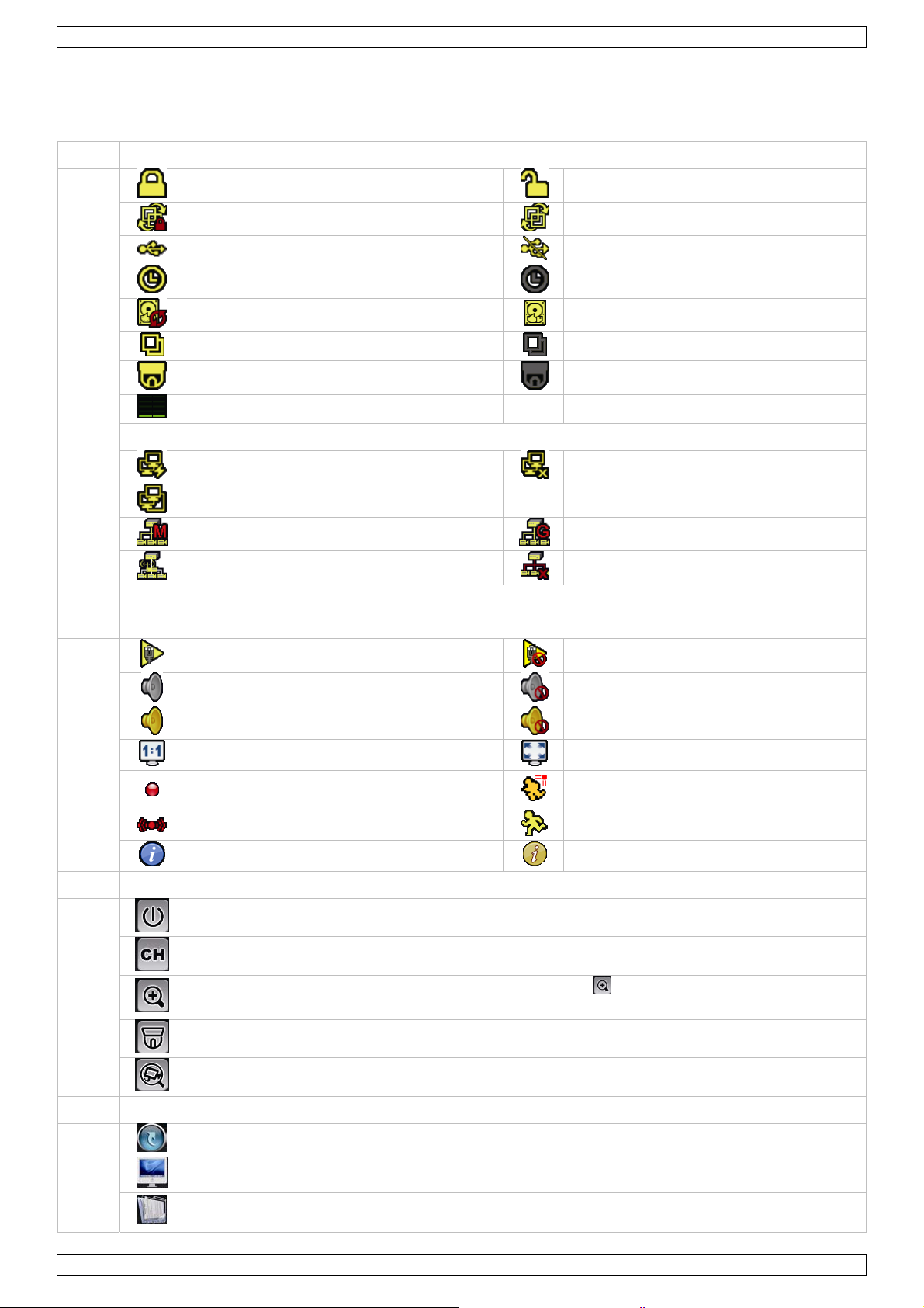
15 NVR status
V. 01 – 23/03/2012 5 ©Velleman nv
key lock
channel lock
USB flash drive / device connected
key unlock
channel unlock
no USB device connected

NVR1
timer recording on
overwrite on
sequence mode on
PTZ mode on
CPU load
network status
(WAN) internet connected
(WAN) local connection
(LAN) auto mode – Mbit/s
(LAN) DHCP / static IP mode
16 available hard disk capacity
17 channel status
auto search on
live audio on
audio playback on
original size
recording
alarm event
live information
18 quick operation
Click to show the power-off panel to stop or reboot the system.
timer recording off
overwrite off
sequence mode off
PTZ mode off
(WAN) internet disconnected
(LAN) auto mode – Gbit/s
(LAN) camera disconnected
auto search off
audio off
audio playback off
fit to screen
human detection event
motion event
playback information
Click to show the channel switch panel and select the channel you want.
Switch to the channel you want first, then click
red frame on the bottom left of the screen to move to the area where you want to zoom in.
Click to enter PTZ mode and show the PTZ camera control panel.
Click to open the IP search window and check the connection status of each channel.
19 main menu
QUICK START Click to set the status display, image settings, and date & time.
SYSTEM Click to set the system configuration.
EVENT
INFORMATION
ADVANCED CONFIG
SCHEDULE SETTING Click to set the recording timer.
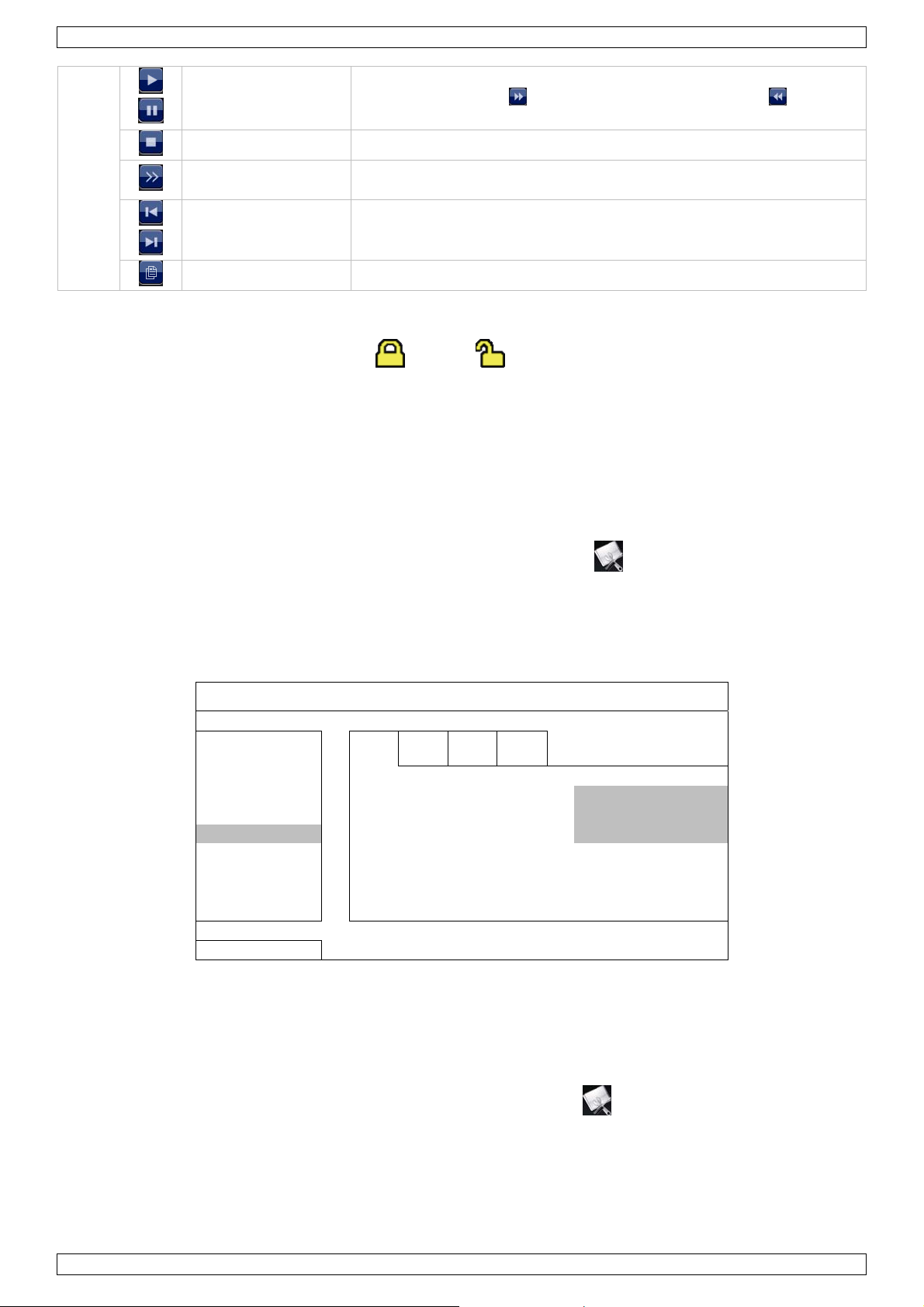
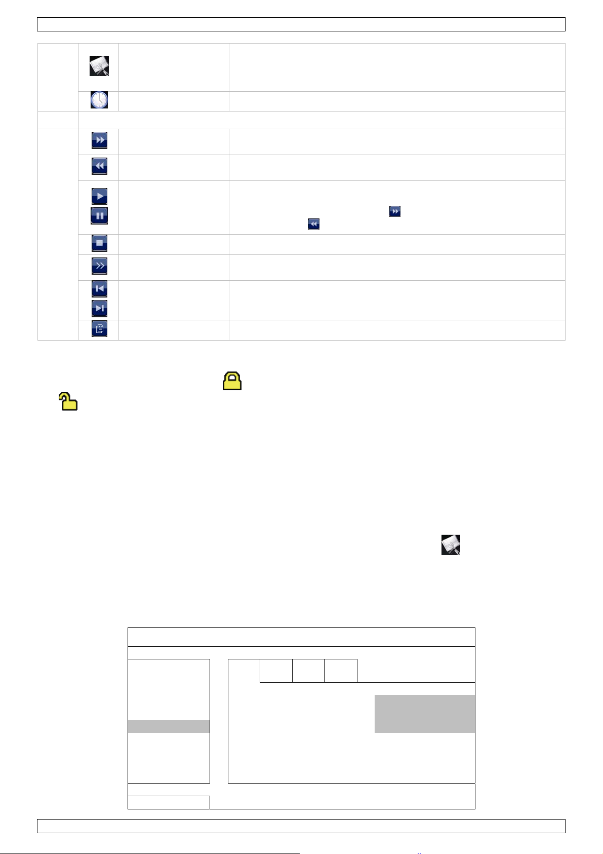
20 playback panel
fast forward Click to fast forward at 4 to 32 times normal speed.
fast rewind Click to fast rewind at 4 to 32 times normal speed.
to enter zoom mode. Click and drag the
Click to enter the event search menu.
Click to set CONNECTION, CAMERA, DETECTION, ALERT, NETWORK,
DISPLAY, RECORD and NOTIFY.
V. 01 – 23/03/2012 6 ©Velleman nv
NVR1
play/pause
stop Click to stop the video playback.
slow playback
previous/next hour
quick search Click to enter the quick search menu.
Key lock / unlock
To lock or unlock NVR local operation, click (lock) or (unlock) on the NVR status panel [15]. When
you unlock NVR local operation, the system asks you to enter a user name and password.
Note: The default user name and password are “admin”. Different user types have different access rights to
NVR functions. For details, please refer to the full manual on the CD-ROM.
Click to play the latest recorded video clip. Click again to pause.
In pause mode, click
one frame backward.
Click once to play at 1/4 normal speed, click twice for 1/8 normal
speed.
Click to jump to the next/previous one-hour time interval (for
example, 11:00 ~ 12:00 or 14:00 ~ 15:00) and start playing the
earliest video clip recorded during this hour.
once to go one frame forward, or to go
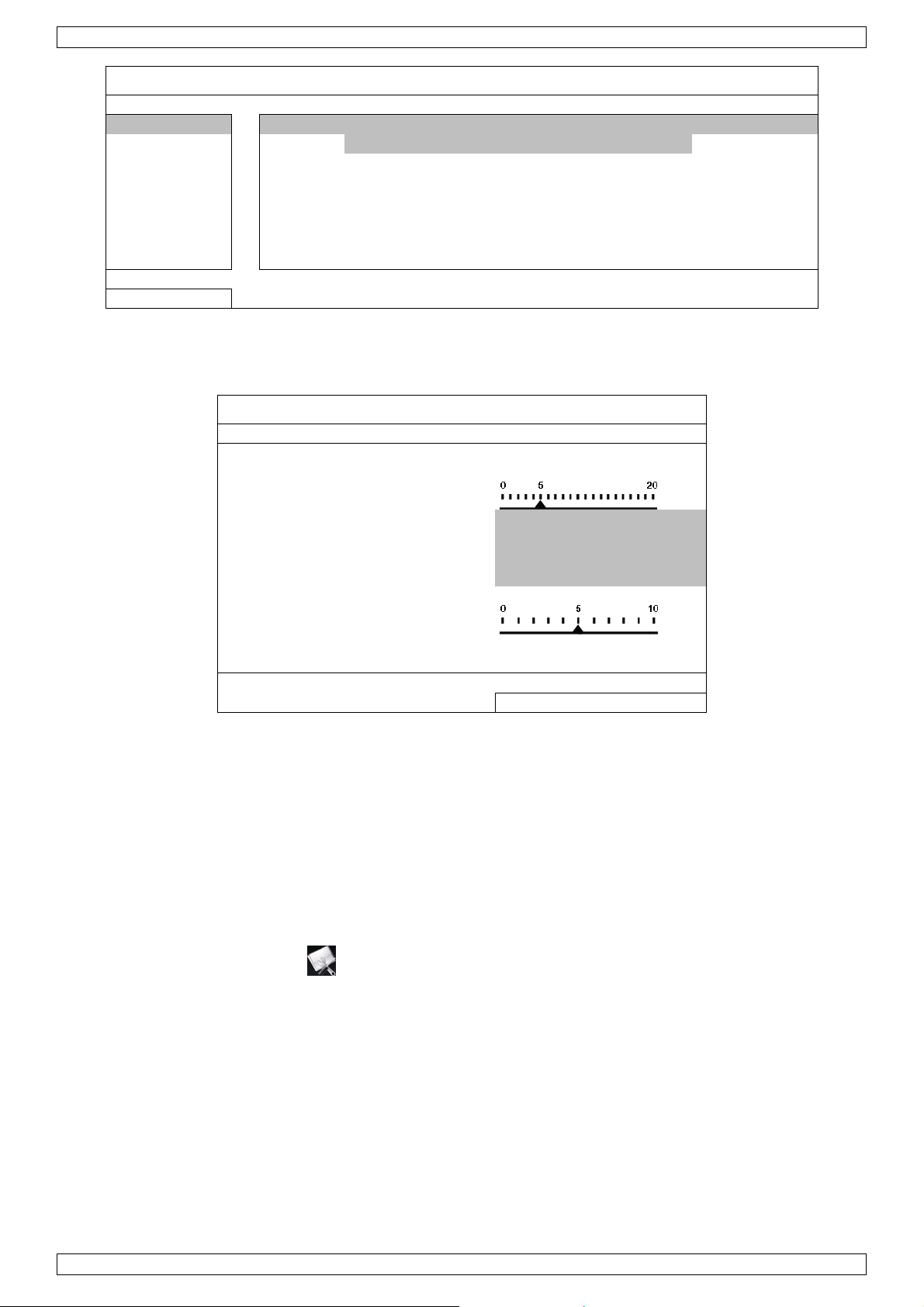
9. Configuration of Camera on WAN Port
Note: This configuration method is for Push Video IP cameras or IP cameras connected via internet (CAMIP9,
CAMIP13, or cameras of a different brand that are ONVIF certified).
NVR WAN IP Address Setting
First set up the WAN IP address of the NVR. In the main menu [19], click (ADVANCED CONFIG) and
select NETWORK > WAN.
• IP: e.g. 192.168.2.10 (for example if the range of the router is: 192.168.2.1 – 192.168.2.254)
• GATEWAY: e.g. 192.168.2.1 (= the IP address of the router)
• NETMASK: 255.255.255.0
ADVANCED CONFIG
CONNECTION WAN LAN E-
DDNS
MAIL
CAMERA NETWORK TYPE STATIC
DETECTION IP 192.168.2.10
ALERT GATEWAY 192.168.2.1
NETWORK NETMASK 255.255.255.0
DISPLAY PRIMARY DNS 168.95.1.1
RECORD SECONDARY DNS 139.175.55.244
NOTIFY PORT 88
EXIT
Configuring a Local Push Video Camera
1. First, follow the installation and configuration instructions in the quick reference guide of your Push Video IP
camera.
2. Make sure that the IP address of the Push Video camera matches the router setting. For example: set the
IP address to 192.168.2.197 and check if the Push Video function works.
3. Add the camera to the NVR as follows: in the main menu [19], click (ADVANCED CONFIG) and
select CONNECTION.
V. 01 – 23/03/2012 7 ©Velleman nv
NVR1
ADVANCED CONFIG
CONNECTION CHANNEL URI PORT CONFIG
CAMERA CH1 192.168.2.197 00088 SETUP
DETECTION CH2 10.1.1.14 00088 SETUP
ALERT CH3 10.1.1.30 00088 SETUP
NETWORK CH4 10.1.1.12 00088 SETUP
DISPLAY CH5 10.1.1.16 00088 SETUP
RECORD CH6 10.1.1.13 00088 SETUP
NOTIFY
EXIT
4. Enter the IP address (URI) and port number (PORT).
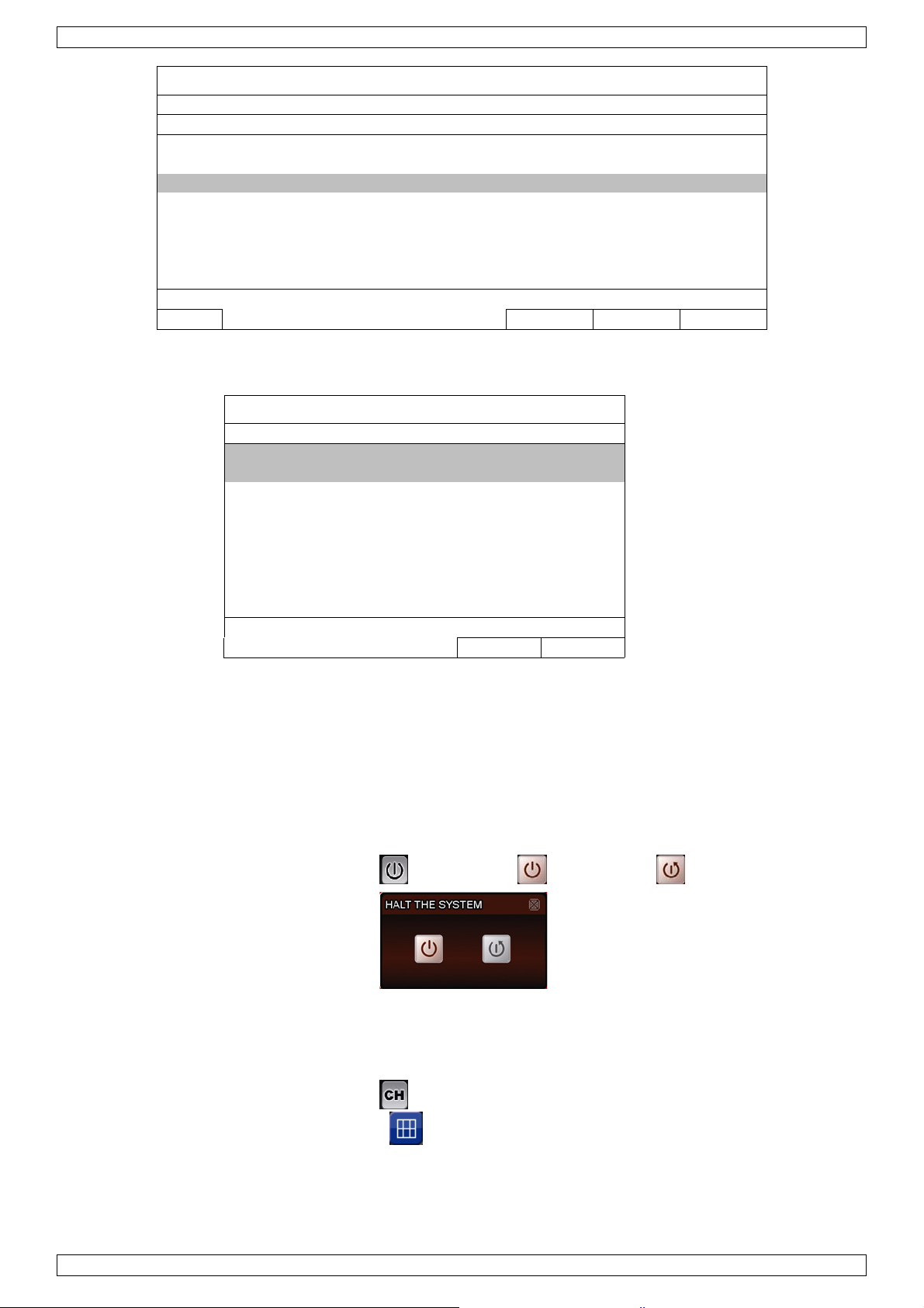
5. Click SETUP to enter the access information of the camera:
CONFIG-CH1
USER NAME admin
PASSWORD **********
CACHE TIME (MSEC)
MODEL AVTECH
GET TYPE IP CAMERA
PROFILE PROFILE-3
TYPE H264
IMAGE SIZE 720 X 480
QUALITY
I.P.S. 30
AUDIO ON
EXIT
6. Enter the user name (USER NAME) and password (PASSWORD) to access the IP camera.
7. Click GET TYPE to detect the camera and make sure the access information is correct.
8. Select the image size (IMAGE SIZE ), image quality (QUALITY), and images per second (I.P.S.).
Note: The available options depend on the camera you want to connect.
9. Click GET TYPE to detect the camera and make sure the access information is correct.
10. Optional: for a camera with audio recording, set AUDIO to ON or OFF.
Configuring a Remote Internet Camera
Via internet you can record video images from an IP camera in a remote location.
1. Make sure that the IP camera is accessible outside its LAN network via a dynamic domain name (for
example ip_office.ddns.eagleeyes.tw).
2. In the main menu [19], click (ADVANCED CONFIG) and select CONNECTION.
V. 01 – 23/03/2012 8 ©Velleman nv

NVR1
ADVANCED CONFIG
CONNECTION CHANNEL URI PORT CONFIG
CAMERA CH1 ip_office.ddns.eagleeyes.tw 00080 SETUP
DETECTION CH2 10.1.1.14 00088 SETUP
ALERT CH3 10.1.1.30 00088 SETUP
NETWORK CH4 10.1.1.12 00088 SETUP
DISPLAY CH5 10.1.1.16 00088 SETUP
RECORD CH6 10.1.1.13 00088 SETUP
NOTIFY
EXIT
3. To assign a channel to a remote IP camera, click URI to enter the address of the camera and its port
number.
4. Click SETUP to enter the access information of the camera.
CONFIG-CH1
USER NAME admin
PASSWORD **********
CACHE TIME (MSEC)
MODEL AVTECH
GET TYPE IP CAMERA
PROFILE PROFILE-3
TYPE H264
IMAGE SIZE 720 X 480
QUALITY
I.P.S. 30
AUDIO ON
EXIT
5. Enter the user name (USER NAME) and password (PASSWORD) to access the IP camera.
6. Click GET TYPE to detect the camera and make sure the access information is correct.
7. Select the image size (IMAGE SIZE ), image quality (QUALITY), and images per second (I.P.S.).
Note: The available options depend on the camera you want to connect.
8. Click GET TYPE to detect the camera and make sure the access information is correct.
9. Optional: for a camera with audio recording, set AUDIO to ON or OFF.
10. Configuration of Camera on LAN Port
Note: This configuration method is for ETS cameras (CAMIP11, CAMIP12).
Automatic Configuration
The NVR will automatically configure the IP address of an ETS camera connected by LAN if:
• The default IP configuration method of the camera is DHCP.
• The camera is powered on before the NVR is powered on.
If not, you can configure the IP address of your camera manually as described further below.
Manual Configuration
If the NVR doesn’t configure the IP address of your camera automatically as described above, the default IP
configuration method of your IP camera may not be set to DHCP. To solve this, reconfigure the camera’s IP
address to 10.1.1.xx (xx ranges from 11 ~ 253), in the same network segment as the NVR.
1. In the quick operation panel [18], click . You’ll see the list of every connected IP camera with its
connection status and MAC address.
V. 01 – 23/03/2012 9 ©Velleman nv
NVR1
IP SEARCH
IP PORT MAC STATUS
10.1.1.12 88 00:0e:53:e5:9a:f1 BE CONNECTED ON CH1
10.1.1.13 88 00:0e:53:a6:91:18 BE CONNECTED ON CH2
10.1.2.14 88 00:0e:53:a5:9f:a2 UNUSE
10.1.1.15 88 00:0e:53:e1:4e:k5 BE CONNECTED ON CH3
10.1.1.16 88 00:0e:53:s5:3e:h6 BE CONNECTED ON CH4
10.1.1.17 88 00:0e:53:e6:4b:26 BE CONNECTED ON CH5
¯² CONNECT SETUP EXIT
2. Select an IP address that is not used (UNUSED), and click SETUP.
SETUP
NETWORK TYPE STATIC
IP 10.1.1.14
PORT 88
USER NAME admin
PASSWORD *****
NETMASK 255.0.0.0
GATEWAY 10.1.1.10
PRIMARY DNS 168.95.1.1
APPLY EXIT
3. Select STATIC in NETWORK TYPE, and change the IP address to 10.1.1.xx (xx ranges from 11 ~ 253).
4. Click APPLY and EXIT to save your changes.
5. Wait until the NVR detects the IP camera and displays images.
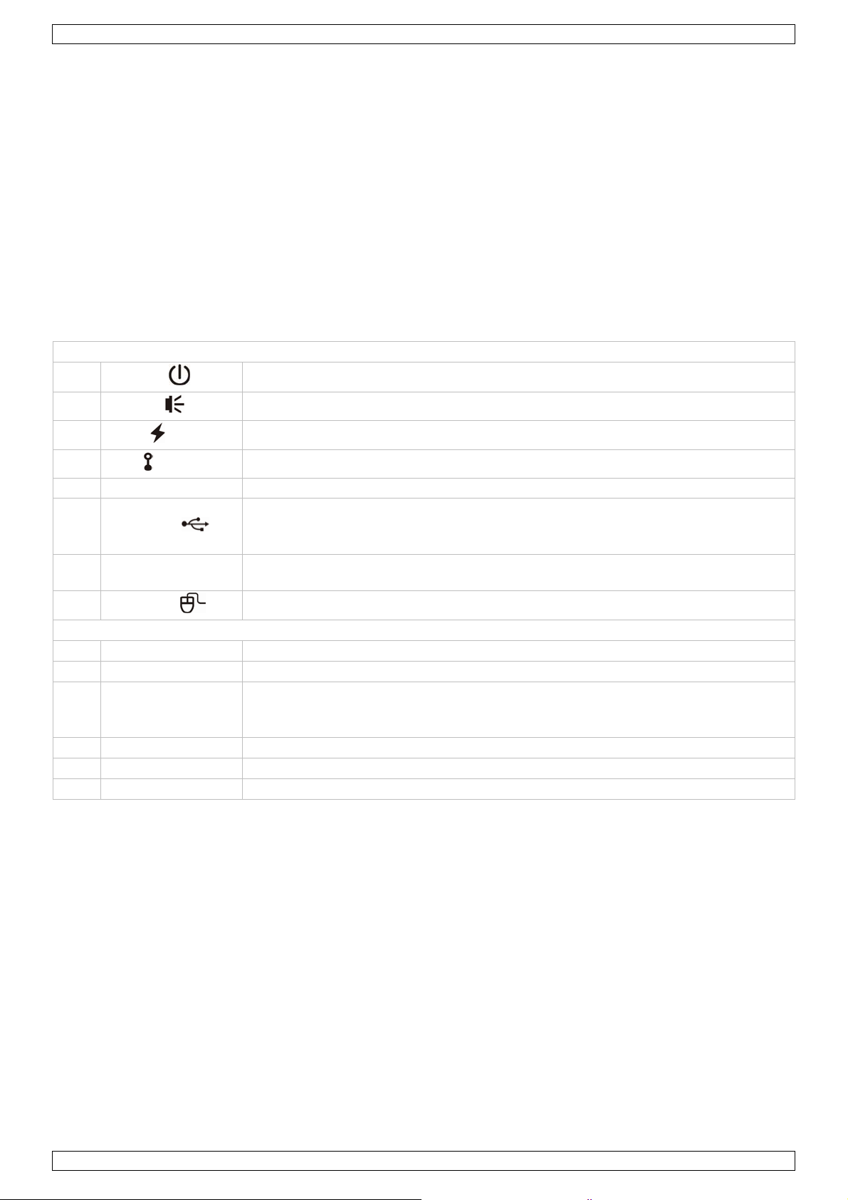
11. Quick Operation
Switching on/off and Rebooting
To power off or reboot the NVR, you can:
• Use the power switch on the NVR rear panel, or
• In the quick operation panel [18], click and then click (power off) or (reboot).
Viewing a Channel in Full-Screen Mode
To view a channel in full screen mode, you can:
• Click directly on the channel image to see that channel in full screen mode. Double-click the image to
restore the 6-channel overview.
• In the quick operation panel [18], click . On the control panel that appears, select the channel you
want to display in full screen mode. Click to restore the 6-channel overview.
V. 01 – 23/03/2012 10 ©Velleman nv

NVR1
Playing Recorded Video Clips
1. Make sure that manual and/or event recording is enabled: in the main menu [19], click (ADVANCED
CONFIG) and select RECORD to check or adjust the settings.
ADVANCED CONFIG
CONNECTION MANUAL RECORD ON
CAMERA EVENT RECORD ON
DETECTION TIMER RECORD OFF
ALERT PRE-ALARM RECORD ON
NETWORK OVERWRITE ON
DISPLAY KEEP DATA LIMIT (DAYS) OFF
RECORD RECORD CONFIG SETUP
NOTIFY
EXIT
2. In the playback panel [20], press the play button . The recorded files are shown.
3. The fast forward and fast rewind buttons increase/decrease the playback speed. Press the button
repeatedly to increase/decrease the speed to 4x, 8x, 16x, or 32x (max.).
4. Press the pause button to pause playback.
5. Press the stop button to stop playback and return to live monitoring.
12. Technical Specifications
video compression H. 264 / MPEG4 / MJPEG
video input 1 LAN port, up to 6 channels with a 6-port hub/switch
video output HDMI output 1920 x 1080 pixels
recording capacity up to 150 ips @ 720P image quality (32Mbps)
hard disk storage SATA x 2, supported HDD capacity up to 3TB
recording mode manual / timer / motion / alarm
multiplex operation live display, record, playback, backup and network
audio I/O 1 audio input, 1 audio output (mono)
motion detection area 22 x 18 grid per camera
motion detection sensitivity 10 adjustable variables with precise calculation for motion detection
pre-alarm recording yes
backup device USB 2.0 backup and network remote backup
web interface • supports free CMS software (Windows & Mac OS)
• all major internet browsers via Java, QuickTime and VLC plug-in (Internet
Explorer, Firefox, Safari, Google Chrome)
remote alarm notification SMS message, e-mail and image uploading to FTP sites
network connection supports TCP/IP, PPPoE, DHCP and DDNS function
V. 01 – 23/03/2012 11 ©Velleman nv

NVR1
alarm I/O 1 input, 1 output
power source 19VDC/2.1A (incl.)
power consumption < 40W
operating temperature 10°C ~ 40°C
system recovery system auto recovery after power reconnected
dimensions 375 x 55 x 264mm
Use this device with original accessories only. Velleman nv cannot be held responsible in the event
of damage or injury resulted from (incorrect) use of this device.
For more info concerning this product and the latest version of this manual, please visit our website
www.velleman.eu.
The information in this manual is subject to change without prior notice.
© COPYRIGHT NOTICE
The copyright to this manual is owned by Velleman nv. All worldwide rights reserved.
No part of this manual or may be copied, reproduced, translated or reduced to any electronic medium or
otherwise without the prior written consent of the copyright holder.
V. 01 – 23/03/2012 12 ©Velleman nv

.
aBeHeDa
.3.
.
n
e
m
y
g
e
c
g
w
d
e
d
k
d
n
e
V
h
e
e
e
c
m
c
e
r
o
g
B
a
r
h
b
o
c
e
r
v
u
t
t
®
k
o
p
n
o
o
i
d
m
3
o
2
v
m
p
p
r
f
h
n
e
a
h
a
k
t
c
o
V
s
o
e
d
d
T
g
s
t
k
e
e
e
g
n
n
k
n
t
m
r
a
e
o
e
e
x
r
w
i
a
a
a
g
t
r
a
e
.
e
a
B
m
m
k
g
e
b
d
e
o
d
u
e
e
o
e
g
f
d
5
n
d
d
e
o
5
g
v
o
c
e
w
k
t
v
t
c
n
v
e
r
a
e
w
v
e
c
e
t
r
e
.
i
g
a
d
A
n
n
r
e
e
e
NVR1
1
Inleidi
A
n alle ing
langrijke
bt u vrage
nk u voor u
be
schadigd tij
2
Veiligh
Dit s
weg
batt
tere
bren
Hou
Ele
om
Trek
het
zetenen v
ilieu-info
mbool op
eworpen, d
rijen) niet
htkomen v
en. Respe
n, contact
aankoop!
ens het tra
idsinst
buiten het
trocutiege
odelijke ele
de stekker
iet gebruik
ekno
n de Euro
matie bet
et toestel o
it toestel sc
ij het gewo
or recyclag
teer de pla
er dan de
Lees deze
nsport, inst
ucties
bereik van
aar bij het
ktroshocks
it het stop
.
te in
ese Unie
effende di
de verpak
ade kan to
e huishoud
. U moet di
tselijke mili
plaatselijk
andleiding
lleer het da
inderen en
openen va
e vermijde
ontact (tre
tallat
product
ing geeft a
brengen a
elijke afval;
t toestel na
uwetgevin
autoritei
rondig voo
n niet en ra
onbevoegd
het toestel
.
niet aan d
ehan
n dat, als h
n het milie
het moet bi
r uw verdel
.
en betreff
u het toest
dpleeg uw
n.
Raak geen
kabel!) vo
leidin
et na zijn le
. Gooi dit t
j een gespe
er of naar e
nd de ver
l in gebrui
dealer.
kabels aan
rdat u het
enscyclus
estel (en e
ialiseerd b
n lokaal re
ijdering.
neemt. W
die onder s
oestel onde
ordt
entuele
drijf
yclagepunt
rd het toest
room staan
houdt en al
el
s u
Algem
Ra
adpleeg de
Leer eerst
•
Om veilig
•
aangebrac
Gebruik h
•
De garanti
•
dealer zal
houden.
Bewaar d
•
Installeer
•
4
Eigens
ne rich
elleman
Gebrui
vloeist
Besche
versto
object.
Besche
de functies
eidsredene
ht valt niet
t toestel en
e geldt niet
de verantw
ze handleid
n gebruik
happen
lijnen
service- e
het toestel
ffen. Plaats
rm tegen st
t geraken.
rm tegen sc
van het toe
mag u gee
nder de ga
kel waarvo
voor schad
ordelijkhei
ng voor ver
it apparaat
n kwaliteit
enkel bin
geen objec
f en extre
oorzie een
hokken. Ve
tel kennen
n wijziginge
rantie.
r het gema
door het n
afwijzen v
ere raadpl
niet voor ill
sgarantie
enshuis.
en gevuld
e temperat
ruimte van
mijd brute
voor u het
n aanbreng
kt is. Bij on
geren van
or defecten
ging.
gale praktij
chteraan d
escherm te
et vloeisto
uren. Zorg
instens 2,
racht tijde
aat gebruik
n. Schade
oordeelkun
epaalde ric
of problem
ken en resp
ze handleid
en regen,
op of naas
at de verlu
cm tussen
s de bedien
en.
oor wijzigi
ig gebruik
htlijnen in d
n die hier r
ecteer iede
ing.
ochtigheid
het toestel
htingsopen
het toestel
ing.
gen die de
ervalt de g
eze handlei
chtstreeks
s privacy.
n opspatte
ngen niet
en elk ande
ebruiker h
rantie.
ing en uw
verband m
de
eft
e
•
opnames i
•
6-kanaals
o real-ti
o slimm
•
bewaking
•
aansluitin
V.
01 – 23/03/2
per se
trigge
n hoge reso
video-opna
e modus:
onde)
opnamem
kanaal tot
p afstand
met de gs
012
lutie
e:
kanalen x
dus (met E
megapixel
ia gratis Ea
via GPRS,
1.3 megapi
S IP-came
leEyes soft
3G of Wi-Fi
el (25 beel
a): 6 kanal
are op iPh
13
en per sec
n x VGA (2
ne, iPad en
nde) + 3 k
beelden p
Android
nalen x VG
r seconde)
(25 beeld
+ event
©Vellema
n
nv
NVR1
• display met grafische gebruikersinterface (GUI), USB-muis
• hoge compatibiliteit en off-site back-up:
o compatibel met de voornaamste IP-cameras die ONVIF-gecertificeerd zijn
o netwerkopslagfunctie voor back-ups van allerhande IP-cameras op het internet
o werkt met gratis Central Management System (CMS) software voor off-site back-ups
• beheer ter plaatse en op afstand, volledig onafhankelijk
• HDMI-uitvoerresolutie tot 1080P
• optionele harde schijf: HD500GB/S, HD1TB/S (niet meegelev.)
• USB muis: GE31010826101, GE31011039100, GE31030414100
• compatibel met: CAMIP9, CAMIP11, CAMIP12, CAMIP13
• optionele router (niet meegelev.): EM4542, EM4553, EM4570, PCRT1.
5. Omschrijving
Raadpleeg de afbeelding op pagina 2 van deze handleiding.
Voorpaneel
1
POWER
2
ALARM
3
WAN
4
LAN
5 RECORD LED indicator: opname is ingeschakeld
6
USB-poort
7 HDD1/HDD2
8
muispoort
Achterpaneel
9 AUDIO OUT Verbind met de audio line-in van een versterker.
10 WAN Verbind met internet via een 8P8C (RJ45) netwerkkabel.
HDMI video
11
uitvoerpoort
12 LAN Verbind met lokale IP-camera’s via een 8P8C (RJ45) netwerkkabel.
13 DC 19V IN Verbind met de voedingsadapter (meegeleverd).
14 aan/uitschakelaar Schakel de NVR in (—) of uit (O).
LED indicator: de NVR is ingeschakeld
LED indicator: een alarm treedt op
LED indicator: de NVR is verbonden met internet
LED indicator: de NVR is verbonden met het LAN-netwerk
Plaats een compatibele USB flash drive voor videobackup.
Opmerking: Voor een lijst van compatibele USB flash drives, zie de volledige
handleiding op de CD-ROM.
LED indicator: tot twee harde schijven zijn geïnstalleerd in de NVR en zijn goed
verbonden
Sluit een compatibele muis aan.
Verbind met een scherm dat high-definition video ondersteunt (HDMI-poort).
Opmerking: Gebruik een geschikte adapter (niet meegelev.) voor schermen met
VGA- of composietvideoconnectoren.
6. De hard disk drive (HDD) installeren
1. Deze NVR is geschikt voor gebruik met een compatibele HDD (niet meegelev.), type SATA (Serial Advanced
Technology Attachment). Formatteer eerst de HDD indien nodig.
2. Ontkoppel het apparaat eerst van het lichtnet. Raak geen elektronische circuits aan om elektrostatische
ontladingen te voorkomen.
3. Schroef het bovendeksel los en neem het weg.
4. Plaats de harde schijf in de voorziene montagebeugel in de NVR.
5. Plaats de harde schijf met de printplaat naar boven en sluit de voedings- en dataconnectoren aan.
6. Bevestig de harde schijf met de meegeleverde schroeven, twee aan elke kant.
V. 01 – 23/03/2012 14 ©Velleman nv
NVR1
7. Gebruik de extra meegeleverde montagebeugels om een tweede harde schijf te installeren. Bevestig ze aan
de bodem van de NVR.
8. Plaats de harde schijf met de printplaat naar boven en sluit de voedings- en dataconnectoren aan.
9. Plaats de harde schijf in de montagebeugels en bevestig met de meegeleverde schroeven, twee aan elke
kant.
10. Plaats het bovendeksel terug en schroef vast.
7. Aansluitdiagram
Opmerking: Om zeker te zijn dat de automatische configuratie goed werkt, sluit eerst de IP-camera’s aan en
schakel ze in. Schakel pas dan de NVR in.
U kunt tot 6 IP-camera’s aansluiten.
Raadpleeg de afbeeldingen op pagina 2 van deze handleiding.
A B
Verbinding op afstand: gebruik deze methode
voor Push Video IP-camera’s en IP-camera’s
verbonden via internet.
1. Geef in de NVR het IP-adres en de
beveiligingsinform a t ie in.
2. Wacht tot u de beelden op het scherm ziet
verschijnen.
C Push Video camera H router
D internet camera I muis
E 8P8C (RJ45) netwerkkabel J NVR achterpaneel
F modem K
G hub/switch L 19VDC voedingsadapter
Lokale verbinding: gebruik deze methode voor
ETS-camera’s.
1. Verbind de camera met een hub/switch.
2. Wacht tot de camera automatisch geconfigureerd
is en de beelden op het scherm verschijnen.
scherm met high-definition videoondersteuning
V. 01 – 23/03/2012 15 ©Velleman nv
NVR1
8. Informatie en panelen op het scherm
Raadpleeg de afbeeldingen op pagina 2 van deze handleiding.
15 NVR-status
netwerkstatus
vergrendeling actief
kanaalvergrendeling actief
USB flash drive / apparaat verbonden
tijdsgeschakelde opname actief
overschrijven actief
sequentiemodus actief
PTZ-modus actief
CPU-belasting
vergrendeling inactief
kanaalvergrendeling ina c t i e f
geen USB-apparaat verbonden
tijdsgeschakelde opname inactief
overschrijven inactief
sequentiemodus inactief
PTZ-modus inactief
(WAN) internet verbonden
(WAN) lokale verbinding
(LAN) auto-modus – Mbit/s
(LAN) DHCP / statische-IP-modus
16 beschikbare ruimte op harde schijf
17 kanaalstatus
18 snelle bediening
automatisch zoeken actief
live-geluid actief
geluid afspelen actief
originele grootte
opname actief
een alarm doet zich voor
live-beelden
Klik om het uitschakelpaneel te tonen en het apparaat uit te schakelen of te herstarten.
(WAN) internet niet verbonden
(LAN) auto-modus – Gbit/s
(LAN) camera niet verbonden
automatisch zoeken inactief
geluid inactief
geluid afspelen inactief
passend op scherm
menselijke aanwezigheid wordt
gedetecteerd
beweging wordt gedetecteerd
afspelen van opgenomen beelden
Klik om het kanaalkeuzepaneel te tonen en een kanaal te kiezen.
Selecteer eerst het kanaal van uw keuze, en klik dan op om in te zoomen. Klik en sleep
het rode kadertje onderaan links in het scherm om in te zoomen op het gebied van uw keuze.
Klik om de PTZ-modus actief te maken en het bedieningspaneel voor PTZ-camera’s te tonen.
Klik om het IP-zoekvenster te tonen en de verbindingsstatus van elk kanaal te controleren.
19 hoofdmenu
V. 01 – 23/03/2012 16 ©Velleman nv
QUICK START Klik voor het instellen van statusweergave, beeld, datum en tijd.
SYSTEM Klik voor systeeminstellingen.
EVENT
INFORMATION
Klik om het zoekmenu voor events te activeren.
NVR1
Klik voor het instellen van verbindingen (CONNECTION), camera’s
ADVANCED CONFIG
SCHEDULE SETTING Klik voor het instellen van tijdsgeschakelde opnames.
20 afspeelpaneel
Vergrendeling
snel vooruit
snel achteruit
afspelen/pauze
stop Klik om de weergave te stoppen.
vertraagde weergave
vorige/volgende uur
snel zoeken Klik om het menu voor snel zoeken actief te maken.
(CAMERA), detectie (DETECTION), meldingen (ALERT), netwerk
(NETWORK), weergave (DISPLAY), opname (RECORD) en
informatieberichten (NOTIFY).
Klik om versneld vooruit af te spelen aan 4 tot 32 keer de normale
snelheid.
Klik om versneld achteruit af te spelen aan 4 tot 32 keer de normale
snelheid.
Klik om de laatst opgenomen videoclip af te spelen. Klik opnieuw om
te pauzeren.
In pauzemodus, klik één keer op om één beeldje vooruit te
springen, of op voor één beeldje achteruit.
Klik één keer om de clip af te spelen aan 1/4 van de normale
snelheid, klik twee keer voor 1/8 van de normale snelheid.
Klik om naar het vorige/volgende interval van één uur te springen
(bijvoorbeeld, 11:00 ~ 12:00 of 14:00 ~ 15:00) en de eerste videoopname in dat tijdsinterval af te spelen.
In het NVR-statuspaneel [15], klik op (vergrend elen) om de bediening van de NVR te vergrendelen, of klik
op (ontgrendelen) om de bediening weer vrij te geven. Wanneer u de bediening weer vrijgeeft, moet u een
gebruikersnaam en wachtwoord ingeven.
Opmerking: De standaard gebruikersnaam en het standaard wachtwoord zijn “admin”. Verschillende
gebruikerstypes hebben verschillende toegangsrechten tot de functies van de NVR. Raadpleeg de volledige
handleiding (beschikbaar op de CD-ROM) voor meer informatie.
9. Camera op WAN-poort instellen
Opmerking: Deze instelmethode is bedoeld voor Push Video IP-camera’s of IP-camera’s die via internet
verbonden zijn (CAMIP9, CAMIP13, of camera’s van een ander merk die ONVIF-gecertificeerd zijn).
Het WAN IP-adres van de NVR instellen
Eerst moet u het WAN IP-adres van de NVR instellen. In het hoofdmenu [19], klik op (ADVANCED
CONFIG) en kies NETWORK > WAN.
• IP: bijvoorbeeld 192.168.2.10 (bv. als de adresreeks van de router 192.168.2 .1 – 192.168.2.254 is)
• GATEWAY: bijvoorbeeld 192.168.2.1 (= het IP-adres van de router)
• NETMASK: 255.255.255.0
ADVANCED CONFIG
CONNECTION WAN LAN ECAMERA NETWORK TYPE STATIC
DETECTION IP 192.168.2.10
ALERT GATEWAY 192.168.2.1
NETWORK NETMASK 255.255.255.0
DISPLAY PRIMARY DNS 168.95.1.1
RECORD SECONDARY DNS 139.175.55.244
NOTIFY PORT 88
EXIT
DDNS
MAIL
V. 01 – 23/03/2012 17 ©Velleman nv
 Loading...