

Page 1
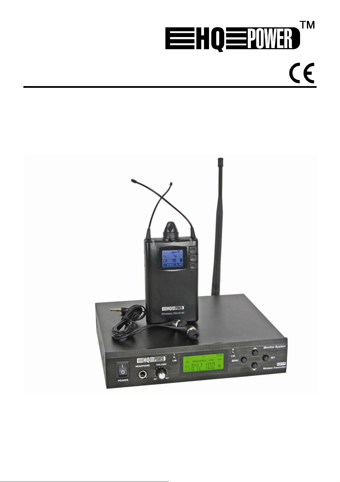
MICW70
WIRELESS UHF IN EAR MONITOR SYSTEM - 48 CHANNELS
DRAADLOOS UHF IN-EAR MONITORINGSYSTEEM - 48 KANALEN
SYSTÈME DE RÉCEPTION UHF INTRA-AURICULAIRE SANS FIL - 48 CANAUX
SISTEMA DE RECEPCIÓN UHF INTRAUDITIVO INALÁMMBRICO - 48 CANALES
DRAHTLOSES UHF IN-EAR MONITORINGSYSTEM - 48 KANÄLE
USER MANUAL 3
GEBRUIKERSHANDLEIDING 8
NOTICE D’EMPLOI 13
MANUAL DEL USUARIO 18
BEDIENUNGSANLEITUNG 23
Page 2
MICW70
T - 1
R - 1
T - 2
00 (09/01/2009) Velleman®
2
R - 2
Page 3
MICW70
User manual
1. Introduction
To all residents of the European Union
Important environmental information about this product
This symbol on the device or the package indicates that disposal of the device after its
lifecycle could harm the environment. Do not dispose of the unit (or batteries) as
unsorted municipal waste; it should be taken to a specialized company for recycling. This
device should be returned to your distributor or to a local recycling service. Respect the
local environmental rules.
If in doubt, contact your local waste disposal authorities.
Thank you for choosing HQPower! Please read the manual thoroughly before bringing this device into
service. If the device was damaged in transit, do not install or use it and contact your dealer. Damage
caused by disregard of certain guidelines in this manual is not covered by the warranty and the
dealer will not accept responsibility for any ensuing defects or problems.
2. Safety Instructions
Keep the device away from children and unauthorised
users.
Indoor use only.
Keep the device away from rain, moisture, splashing and
dripping liquids. Never put objects filled with liquid on top
of or close to the device
Be very careful during the installation: touching live wires
can cause life-threatening electroshocks.
Protected the device against extreme heat and dust.
• Damage caused by disregard of certain guidelines in this manual is not covered by the warranty and
the dealer will not accept responsibility for any ensuing defects or problems.
• Note that damage caused by user modifications to the device is not covered by the warranty.
• A qualified technician should install and service this device.
• Contact a local dealer for spare parts.
• Do not crimp the power cord and protect it against damage. Have an authorised dealer replace it if
necessary.
• Make sure that the available voltage does not exceed the voltage stated in the specifications of
this manual.
• Disconnect the device from the mains to clean or when not in use. Handle the power cord by the
plug or adaptor only.
• Refer to the table below for the sound pressure level vs. exposure time before ear damage might
occur. The sound pressure level of the headphone is 90dB in normal circumstances.
90dB 8h
95dB 4h
100dB 2h
105dB 1h
110dB 30min
115dB 15min
120dB immediate damage possible
00 (09/01/2009) Velleman®
3
Page 4

MICW70
3. General Guidelines
• This device is designed for professional use on stage, in discos, theatres, etc. The MICW70 should
only be used indoors with the included adaptor or with one with the same rating. This device is not
designed for permanent operation: regular operation breaks will prolong its live.
• Protect this device from shocks and abuse. Avoid brute force when operating the device.
• Do not switch the device on immediately after it has been exposed to changes in temperature.
Avoid damage to the device by letting it stabilise to room temperature before switching it on.
• Familiarise yourself with the functions of the device before actually using it.
• All modifications of the device are forbidden for safety reasons.
• Only use the device for its intended purpose. Using the device in an unauthorised way will void the
warranty.
• Transport the device in its original package.
4. Features
• complete in-ear monitoring system
• UHF PLL
• Kit includes:
receiver
transmitter with power adaptor and detachable antenna
in-ear earphones, with adaptors in 3 sizes
19” rack mounting bracket
2x 6.35mm mono-jack cable (L: 1m)
2x battery AA 1.5V
Protective case
5. Overview
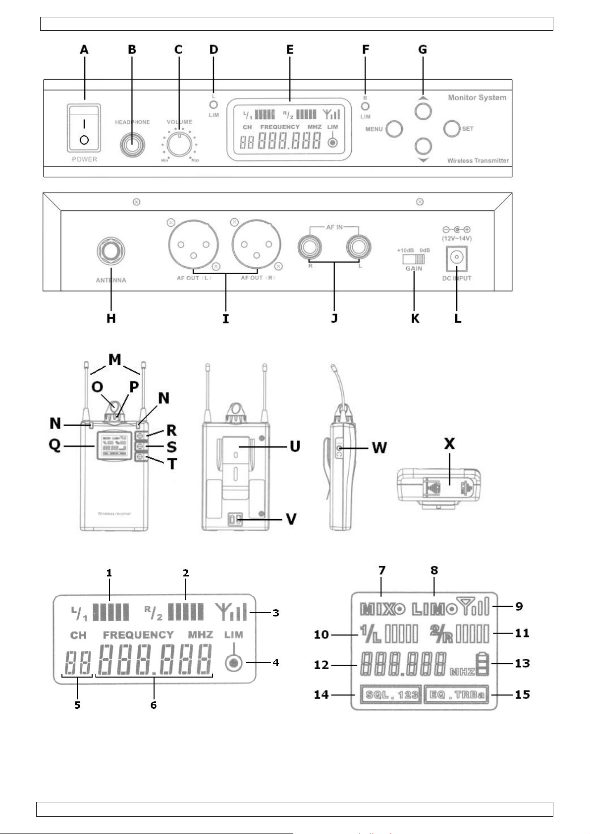
Transmitter (see figure T - 1, page 2)
A power switch G menu, set, up- and down buttons
B headphone output jack H antenna connector
C headphone volume control I audio output
D indicator / volume limiter (channel 2) J audio input
E LCD display K audio gain control
F indicator / volume limiter (channel 1) L DC power jack
Receiver (see figure R - 1, page 2)
M antenna’s S up button
N indicator of active antenna T down button
O power ON/OFF & volume control U belt clip
P audio control – balance V battery polarity mark
Q LCD display W headphone jack
R set button X battery compartment
Transmitter LCD (see figure T - 2, page 2)
1 audio level indicator (channel 1) 4 on/off indicator for limiter
2 audio level indicator (channel 2) 5 channel indicator
3 power transmission indicator 6 frequency indicator
Receiver LCD (see figure R - 2, page 2)
7 stereo/mono 2/mix output indication 12 channel / frequency indicator
8 volume limiting indication 13 battery indicator
9 antenna signal strength 14 squelch setting
10 channel 1 audio level 15 equalizer setting
11 channel 2 audio level
00 (09/01/2009) Velleman®
4
Page 5
MICW70
6. Use
Transmitter
• Place the transmitter in a suitable location (see safety instructions). Mounting brackets to mount
the transmitter in a 19” rack are included.
• Plug the power adapter in the [L] and plug the adapter in the mains.
• Connect the audio outputs to an external audio source e.g. CD-mixer (not incl.) using the included
audio cables. When applicable, connect the audio outputs to another device.
• Screw the included antenna on the antenna connector [H].
• Switch on the transmitter with the power switch [A].
• A headphone (not incl.) can be connected to the transmitter [B] when desired. The output volume
of the headphone jack can be set with the rotary knob [C].
• Set the output channel/frequency using the pushbuttons [G]. Press the set-button to enter set-up
mode. The frequency starts flashing. Use the up- or down button to select a new frequency. Note
that the channel number automatically changes when the frequency changes. Press the set-button
again to save changes and exit set-up-mode. Note that set-up automatically exits after ±10s when
no input is detected.
• To set the volume limiter, set the maximum allowed volume, press the set-button followed by the
menu-button until the LIM-indication [4] flashes. Use the up- or down button to switch the limiter
on or off (ON = ). When switched on, the volume will be limited to the set volume. Press the setbutton again to save changes and exit set-up-mode.
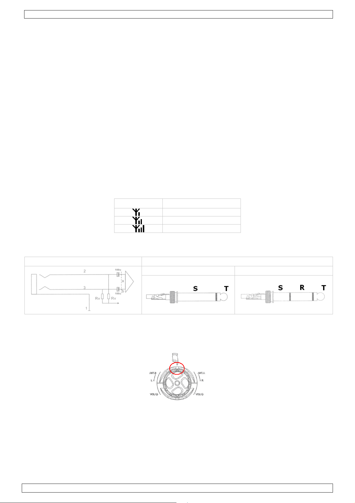
• The transmission power can be set to 3 different levels. To do this, press the set-button followed
by the menu-button until the antenna-indication [3] flashes. Use the up- or down button to set
the power:
indication transmitting power
• Set the gain control switch [K] at the back of the transmitter to 0dB or +10dB to set the input
gain.
• The strength of the input signals is indicated on the display [1] & [2].
input jack input connector
unbalanced balanced
≤ 10dBM
≤ 15dBM
≤ 20dBM
Receiver
• See §9 for instructions on battery installation.
• Switch the receiver on by rotating the power ON/OFF & volume control button [O] clockwise.
• Use the balance control ring [P] to control the balance. When the bulge is lined up with the notch
(see image below), audio left and right are symmetrical.
• Set the channel/frequency to the same value as the transmitter. To do this, press and hold either
the up ([S]) or down ([T]) button until the channel/frequency indicator [12] flashes. Use the set
button [R] to choose between channel or frequency display and use the up ([S]) or down ([T])
button to select a new channel or frequency. Set-up automatically saves and exits after ±10s.
• Press the set-button [R] to scroll through the different settings (MIX [7], LIM [8], SQL [14] and
EQ [15]. The current setting flashes.
o MIX [7]: press up ([S]) or down ([T]) to switch mixed mode on (= ) or off (see §7 for
background information).
o LIM [8]: to set the volume limiter, set the maximum allowed volume and press up ([S]) or
down ([T]) to switch mixed mode on () or off.
00 (09/01/2009) Velleman®
5
Page 6
MICW70
o SQL [14]: press up ([S]) or down ([T]) to set the squelch threshold to level 1, 2 or 3 (see §7
for background information).
o EQ [15]: press up ([S]) or down ([T]) to select the equalizer setting:
EQ.TR Treble boost +6dB
EQ. Ba Bass boost +6dB
EQ.TRBa Treble + Bass boost +6dB
EQ. flat (no boost)
• The active antenna is indicated with a green LED [N]. The antenna power is indicated on the
display [9]. The received strength of the channels is also indicated on the display [10] & [11].
• Plug the earphone into the earphone jack [W] and insert the earplugs into the ears. Replace the
rubber caps with a more comfortable size when necessary.
• The receiver can be attached to a belt with the belt clip [U].
7. Background information
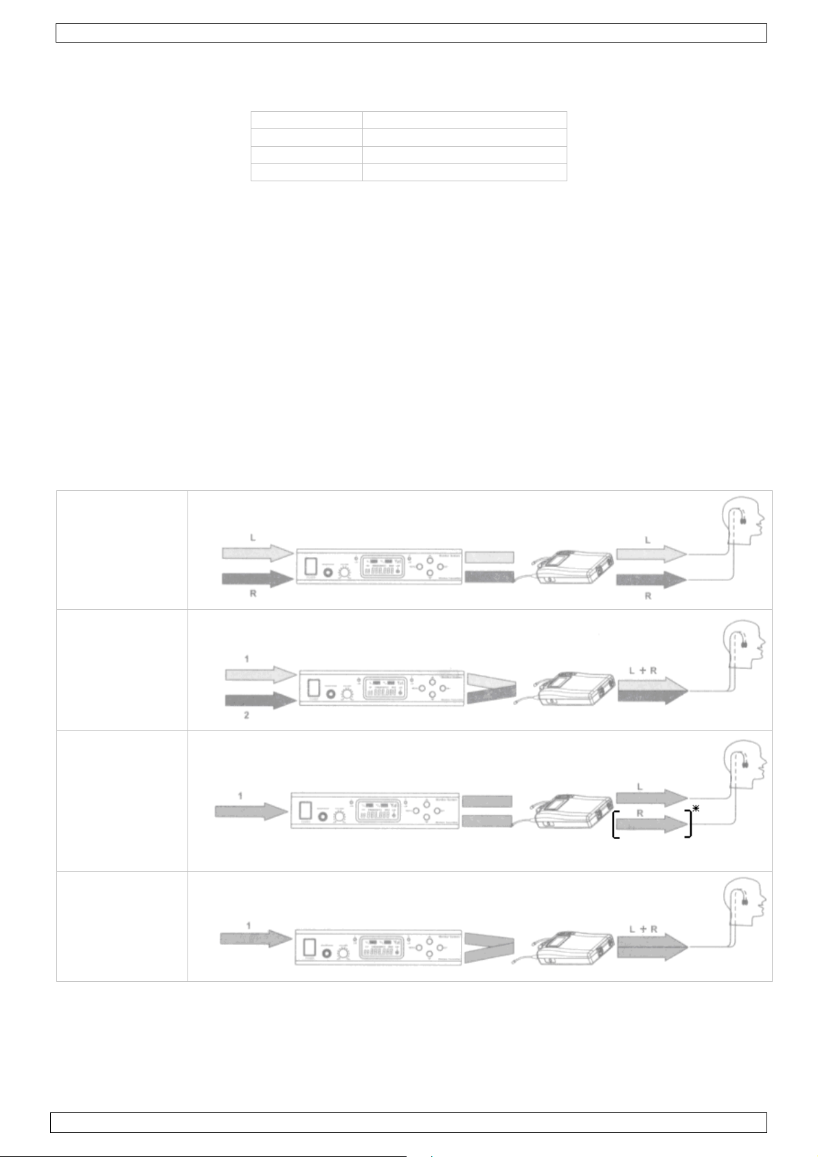
MIX mode/ stereo control
The receiver receives two signals from the transmitter. These two signals are then processed in
either mixed mode or stereo mode.
• In stereo mode, the signals remain separated, meaning that one signal is heard in the left
earphone, while the other one is heard in the right earphone. The balance between the signals
can be controlled with the balance knob [P]. Turing the knob to one side will cause one signal to
disappear.
• In MIX(ed) mode, input signals are mixed into a mono signal before sent into both earphones.
The balance control determines the blend of the input signals.
• When only a single mono signal is available from the audio source, it can be sent to either one
earphone, or mixed and sent to both earphones.
stereo mode
2x mono mode
mixed
mono mode
mono mode
mixed
*Signal to left or right earphone
Squelch
The squelch function can suppress undesired interference signals from other transmission links.
• Switch off the transmitter.
• When the receiver still receives a signal, increase the squelch threshold until the signal is gone.
Note that by doing this, the transmission range will reduce.
• If the interference signal remains, choose a new channel/frequency for transmitter and receiver.
00 (09/01/2009) Velleman®
6
Page 7

MICW70
8. Cleaning
• Wipe the device regularly with a moist, lint-free cloth. Do not use abrasive solutions, alcohol or
solvents.
9. Batteries
• When the battery indicator [13] indicates low battery, replace the batteries with new ones.
• Switch off the receiver before removing the batteries.
• To open the battery cover [X], push on it and slide towards the middle of the receiver.
• Remove the 2 1.5V AA batteries and replace them with to new ones of the same type. Follow the
polarity instructions [V] on the back of the receiver.
• Close the battery compartment and slide it back in place (towards edge of receiver).
WARNING: Dispose of batteries in accordance with local regulations.
Keep the battery away from children.
10. Technical specifications
transmitter receiver
frequency range 840.000 ~ 865.000MHz
bandwidth 25MHz
oscillation mode PLL synthesized
frequency stability ± 0.005% 0°C ~ + 50°C
modulation FM stereo
output power low :< 10mW, high :< 100mW 2 x 50mW @ 1KHz (T.H.D. 3%)
spurious rejection -60dBc
max. deviation range 25 KHz ± 68 KHz
frequency response 50~15,000Hz 80-15,000Hz, ±3dB
T.H.D. < 0.5% (at maximum deviation
range at 1 KHz)
audio output Line level balanced, XLR
audio input 6.3mm phone jack balanced &
unbalanced)
headphone output 6.3mm stereo phone jack with
adjustable volume
headphone output impedance 16Ω
antenna connector TNT (50Ω impedance) receiving mode - diversity receiving
receiving sensitivity - -107 dBm
squelch level - -100dBm -90dBm -70dBm
S/N ratio - max. 94dBA
stereo separation - 35dB
power supply 14VDC - 500mA (incl.) 2 AA batteries LR6C, incl.
dimensions 210 x 175 x 45mm 123 x 65 x 27mm
weight ±1.02kg ±173g (batt. incl.)
Use this device with original accessories only. Velleman nv cannot be held responsible in
the event of damage or injury resulted from (incorrect) use of this device.
For more info concerning this product, please visit our website www.velleman.eu.
The information in this manual is subject to change without prior notice.
3.5mm stereo headphone jack
1%
-
≥ 16Ω
00 (09/01/2009) Velleman®
7
Page 8
MICW70
Gebruikershandleiding
1. Inleiding
Aan alle ingezetenen van de Europese Unie
Belangrijke milieu-informatie betreffende dit product
Dit symbool op het toestel of de verpakking geeft aan dat, als het na zijn levenscyclus
wordt weggeworpen, dit toestel schade kan toebrengen aan het milieu. Gooi dit toestel (en
eventuele batterijen) niet bij het gewone huishoudelijke afval; het moet bij een
gespecialiseerd bedrijf terechtkomen voor recyclage. U moet dit toestel naar uw verdeler of
naar een lokaal recyclagepunt brengen. Respecteer de plaatselijke milieuwetgeving.
Hebt u vragen, contacteer dan de plaatselijke autoriteiten inzake verwijdering.
Dank u voor uw aankoop! Lees deze handleiding grondig voor u het toestel in gebruik neemt. Werd
het toestel beschadigd tijdens het transport, installeer het dan niet en raadpleeg uw dealer.
2. Veiligheidsinstructies
Houd dit toestel uit de buurt van kinderen en onbevoegden.
Enkel voor gebruik binnenshuis.
Bescherm dit toestel tegen regen vochtigheid en
opspattende vloeistoffen. Plaats geen object gevuld met
vloeistof op de ontvanger.
Wees voorzichtig bij de installatie: raak geen kabels aan die
onder stroom staan om dodelijke elektroshocks te
vermijden.
Bescherm dit toestel tegen extreme hitte en stof.
• De garantie geldt niet voor schade door het negeren van bepaalde richtlijnen in deze handleiding
en uw dealer zal de verantwoordelijkheid afwijzen voor defecten of problemen die hier
rechtstreeks verband mee houden.
• Schade door wijzigingen die de gebruiker heeft aangebracht aan het toestel vallen niet onder de
garantie.
• Laat dit toestel installeren en onderhouden door een geschoolde technicus.
• Bestel eventuele reserveonderdelen bij uw dealer.
• De voedingskabel mag niet omgeplooid of beschadigd zijn. Laat uw dealer zo nodig een nieuwe
kabel plaatsen.
• De beschikbare netspanning mag niet hoger zijn dan de spanning in de specificaties achteraan de
handleiding.
• Trek de stekker uit het stopcontact (trek niet aan de kabel!) voordat u het toestel reinigt en als u
het niet gebruikt.
• Raadpleeg de tabel hieronder aangaande het geluidsniveau vs. blootstelling alvorens uw
monitoringsysteem te gaan gebruiken. Het geluidsniveau van de oortjes bedraagt 90 dB bij normaal
gebruik.
90 dB 8u
95 dB 4 u
100 dB 2 u
105 dB 1 u
110 dB 30 min.
115 dB 15 min.
120 dB onmiddellijke gehoorschade
00 (09/01/2009) Velleman®
8
Page 9
MICW70
3. Algemene richtlijnen
• Dit toestel is ontworpen voor professioneel gebruik op podia, in disco's, enz. U mag dit toestel
enkel binnenshuis gebruiken door de meegeleverde adapter aan te sluiten op een wisselspanning
van maximum 230 VAC / 50 Hz. Dit monitoringsysteem is niet ontworpen voor continue werking:
regelmatige onderbrekingen doen het langer meegaan.
• Bescherm dit toestel tegen schokken. Vermijd brute kracht tijdens de bediening van dit toestel.
• Om beschadiging te vermijden, zet u het toestel best niet aan onmiddellijk nadat het werd
blootgesteld aan temperatuurschommelingen. Wacht tot het toestel op kamertemperatuur
gekomen is.
• Leer eerst de functies van het toestel kennen voor u het gaat gebruiken.
• Om veiligheidsredenen mag de gebruiker geen wijzigingen aanbrengen aan het toestel.
• Gebruik het toestel enkel waarvoor het gemaakt is. Bij onoordeelkundig gebruik vervalt de
garantie.
• Gebruik de oorspronkelijke verpakking wanneer u het toestel vervoert.
4. Eigenschappen
• compleet in-ear monitoringsysteem
• UHF PLL
• geleverd met:
ontvanger
zender met voedingsadapter en verwijderbare antenne
oortjes met dopjes in 3 maten
beugel voor montage in 19”-kolom
2x monokabel met 6,35 mm-aansluiting (lengte: 1 m)
2x AA-batterij van 1,5 V
beschermkoffer
5. Omschrijving
Zender (zie figuur T - 1, pagina 2)
A voedingsschakelaar G instelknoppen
B aansluiting hoofdtelefoon H aansluiting antenne
C volumeregeling hoofdtelefoon I audio-uitgang
D aanduiding volumebegrenzer (kanaal 2) J audio-ingang
E lcd-scherm K gainregeling audio
F aanduiding volumebegrenzer (kanaal 1) L aansluiting voedingsadapter
Ontvanger (zie figuur R - 1, pagina 2)
M antennes S
N aanduiding actieve antenne T
O aan-uitschakelaar + volumeregeling U riemclip
P balansregeling V polariteitsaanduiding batterij
Q lcd-scherm W aansluiting oortjes
R instelknop X batterijvak
Lcd-scherm zender (zie figuur T - 2, pagina 2)
1 aanduiding audioniveau (kanaal 1) 4 aanduiding in-/uitschakeling begrenzer
2 aanduiding audioniveau (kanaal 2) 5 aanduiding kanaal
3 aanduiding signaalststerkte 6 aanduiding frequentie
Lcd-scherm ontvanger (zie figuur R - 2, pagina 2)
7 aanduiding uitgang (stereo/mono 2/mix) 12 aanduiding kanaal/frequentie
8 aanduiding volumebegrenzer 13 aanduiding batterijniveau
9 aanduiding signaalststerkte 14 squelchinstelling
10 channel 1 audio level 15 equalizerinstelling
11 channel 2 audio level
00 (09/01/2009) Velleman®
9
Page 10

MICW70
6. Gebruik
Zender
• Installeer de zender op een geschikte plaats (zie ‘Veiligheidsintructies’). Dit systeem wordt
geleverd met een beugel voor montage in een 19”-kolom.
• Plug de meegeleverde voedingsadapter in de voedingsaansluiting [L] en koppel de adapter aan
het lichtnet.
• Sluit de audio-uitgangen aan een externe audiobron (bv. mengtafel) met behulp van de
meegeleverde audiokabels. Sluit de audio-uitgangen aan een ander toestel indien gewenst.
• Schroef de antenne in de aansluiting [H].
• Schakel de zender in via de voedingsschakelaar [A].
• Sluit een hoofdtelefoon (niet meegeleverd) aan de zender via de aansluiting [B] indien gewenst.
Regel het volume naar deze hoofdtelefoon bij met de regelknop [C].
• Stel uitgang/frequentie in met behulp van de instelknoppen [G]. Druk op SET om het instelmenu
weer te geven. De frequentie knippert op de display. Selecteer nu een frequentie naar keuze met
of en bevestig door opnieuw op SET te drukken. U verlaat het instelmenu automatisch na
± 10 seconden.
• Instellen van de volumebegrenzer: Bepaal het maximum toegelaten volumeniveau met draaiknop
[C], druk op SET en daarna op MENU tot de LIM-aanduiding [4] op de display knippert. Schakel
de begrenzer in/uit met
volumeniveau niet overschreden worden. Bewaar uw instellingen en verlaat het menu met een
druk op SET.
• De zender heeft drie instelbare zendsterktes. Druk op SET en daarna op MENU tot
display. Stel de sterkte in met
• Stel de ingangsgain (0 dB of +10 dB) in met schakelaar [K] achteraan de ontvanger.
• De sterkte van de ingangssignalen wordt op de display [1][2] weergegeven.
ingangsaansluiting connector
of ( = ingeschakeld). Indien ingeschakeld, zal het ingestelde
[3] op de
of :
aanduiding sterkte
niet-gebalanceerd gebalanceerd
≤ 10dBM
≤ 15 dBM
≤ 20 dBM
Ontvanger
• Plaats de batterijen in de ontvanger volgens de instructies onder §9.
• Schakel de ontvanger in door de aan-uitschakelaar [O] naar rechts te draaien.
• Regel de balans bij met de balansregeling [P]. De balans voor audiokanalen links en rechts is
symmetrisch afgesteld wanneer de uitstulping van de regelknop in de insnijding staat (zie figuur
hieronder).
• Kies hetzelfde kanaal als dat van de zender. Houd hiervoor de omhoogknop [S] of de omlaagknop
[T] ingedrukt tot de aanduiding voor kanaal/frequentie [12] op de display knippert. Selecteer de
kanaal- of frequentieweergave met SET [R] en kies het kanaal of de frequentie met
[T]. De zender bewaart de instelling en verlaat het menu automatisch na ± 10 seconden.
• Scroll door de opties MIX [7], LIM [8], SQL [14] en EQ [15] met SET [R]. De geselecteerde
optie knippert op de display.
o MIX [7]: schakel de MIX-optie in (= ) of uit met
‘Achtergrondinformatie’).
o LIM [8]: stel het niveau van de volumebegrenzer in en schakel de optie in (= ) of uit met
[S] of
[T].
[S] of [T] (zie §7
[S] of
00 (09/01/2009) Velleman®
10
Page 11

MICW70
o SQL [14]: stel het squelchniveau in op 1, 2 of 3 met
‘Achtergrondinformatie’).
o EQ [15]: stel de equalizer in met
EQ.TR boost van de hoge tonen met +6 dB
EQ. Ba boost van de bassen met +6 dB
EQ.TRBa boost van de hoge tonen en de bassen met +6 dB
EQ. geen boost
• Een actieve antenne wordt aangeduid door de groene led [N], de ontvangststerkte [9] en de
signaalsterkte van de kanalen [10][11] worden weergegeven op de display.
• Koppel de oortjes aan de zender via de aansluiting [W]. Vervang de rubber dopjes en kies de
geschikte maat indien nodig.
• Bevestig de ontvanger aan uw riem met behulp van de riemclip [U].
[S] of [T]:
[S] of [T] (zie §7
7. Achtergrondinformatie
De MIX-optie/stereo
Dit monitoringsysteem zendt een dubbel signaal uit dat wordt gesplitst in een stereo- of een dubbel
monosignaal (MIX-optie).
• Bij een stereosignaal blijft het signaal gescheiden. Dit wil zeggen dat u het linkersignaal in het
linkeroortje te horen krijgt en het rechtersignaal in het rechteroortje. De balans tussen deze twee
signalen kunt u met de balansregeling [P] bijstellen.
• In de MIX-optie wordt het dubbel signaal gemixt in een monosignaal alvorens het naar beide
oortjes wordt verzonden. De balansregeling doet hier dienst als mengknop.
• Is er slechts een enkel monosignaal verkrijgbaar, dan kunt u dit signaal verzenden naar een enkel
oortje of mixen en verzenden naar beide oortjes.
stereo
2x mono gemixt
mono
mono gemixt
*signaal naar linker- of rechteroortje
Squelch
De squelch is een ruisonderdukker die ongewenste signalen uitschakelt.
• Schakel de zender uit.
• Verhoog het squelchniveau indien de ontvanger nog steeds signalen ontvangt. Merk op dat door
het squelchniveau te verhogen u het zendbereik vermindert.
• Kies een nieuw kanaal/frequentie op zowel de zender als op de ontvanger bij aanhoudende
signaalontvangst.
00 (09/01/2009) Velleman®
11
Page 12

MICW70
8. Onderhoud
• Maak het toestel geregeld schoon met een vochtige, niet pluizende doek. Gebruik geen alcohol of
solvent.
9. De batterijen
• Vervang de batterijen in de ontvanger van zodra de aanduiding [13] op de display verschijnt.
• Schakel de ontvanger uit en open het batterijvak [X] door lichtjes op de deksel te drukken en deze
naar achter te glijden.
• Verwijder de oude batterijen en plaats 2 nieuwe AA-batterijen van 1,5 V. Respecteer de
polariteitsaanduidingen [V].
• Sluit het batterijvak.
LET OP: Observeer de richtlijnen op de verpakking van de batterijen. Houd de
batterij uit de buurt van kinderen.
10. Technische specificaties
zender ontvanger
frequentiebereik 840.000 ~ 865.000 MHz
bandbreedte 25 MHz
oscillatie PLL synthesized
frequentiestabiliteit ± 0,005 % (0°C ~ + 50°C)
modulatie FM stereo
vermogen low: < 10 mW, high: < 100 mW 2 x 50 mW @ 1 kHz (THD 3 %)
strooi-emissie -60 dBC
max. afwijking 25 kHz ± 68 kHz
frequentierespons 50 ~ 15.000 Hz 80-15.000 Hz, ± 3 dB
THD < 0,5 % (@ max. afwijking van
1 kHz)
audio-uitgang gebalanceerde XLR
audio-ingang 6,3 mm stereo gebalanceerd &
niet-gebalanceerd)
uitgang hoofdtelefoon 6,3 mm stereo met regelbaar
volume
uitgangsimpedantie hoofdtelefoon 16 Ω
aansluiting antenne TNT (50 Ω) -
ontvangstmodus - diversity
gevoeligheid - -107 dBm
squelchniveau - -100 dBm -90 dBm -70 dBm
S/R-verhouding - max. 94 dBA
stereoscheiding - 35 dB
voeding 14 VDC - 500 mA (meegelev.) 2x AA-batterij LR6C, meegelev.
afmetingen 210 x 175 x 45 mm 123 x 65 x 27 mm
gewicht ± 1,02 kg ± 173 g (met batterij)
Gebruik dit toestel enkel met originele accessoires. Velleman nv is niet aansprakelijk voor
schade of kwetsuren bij (verkeerd) gebruik van dit toestel. Voor meer informatie omtrent
dit product, zie www.velleman.eu
worden gewijzigd zonder voorafgaande kennisgeving.
. De informatie in deze handleiding kan te allen tijde
1 %
-
3,5 mm stereo
≥ 16 Ω
00 (09/01/2009) Velleman®
12
Page 13

MICW70
NOTICE D’EMPLOI
1. Introduction
Aux résidents de l'Union européenne
Des informations environnementales importantes concernant ce produit
Ce symbole sur l'appareil ou l'emballage indique que l’élimination d’un appareil en fin de
vie peut polluer l'environnement. Ne pas jeter un appareil électrique ou électronique (et
des piles éventuelles) parmi les déchets municipaux non sujets au tri sélectif ; une
déchèterie traitera l’appareil en question. Renvoyer les équipements usagés à votre
fournisseur ou à un service de recyclage local. Il convient de respecter la réglementation
locale relative à la protection de l’environnement.
En cas de questions, contacter les autorités locales pour élimination.
Nous vous remercions de votre achat ! Lire la présente notice attentivement avant la mise en
service de l’appareil. Si l’appareil a été endommagé pendant le transport, ne pas l’installer et
consulter votre revendeur.
2. Prescriptions de sécurité
Garder le système hors de la portée de personnes non
qualifiées et de jeunes enfants.
Pour usage à l’intérieur uniquement.
Protéger le système contre la pluie, l’humidité et les
projections d’eau. Ne jamais placer d’objet contenant un
liquide sur l’émetteur.
Être prudent lors de l’installation : toucher un câble sous
tension peut causer des électrochocs mortels.
Protéger le système contre les températures extrêmes et la
poussière.
• La garantie ne s’applique pas aux dommages survenus en négligeant certaines directives de cette
notice et votre revendeur déclinera toute responsabilité pour les problèmes et les défauts qui en
résultent.
• Les dommages occasionnés par des modifications à l’appareil par le client ne tombent pas sous la
garantie.
• Confier l’installation et l’entretien à un personnel qualifié.
• Commander des pièces de rechange éventuelles chez votre revendeur.
• Le câble d’alimentation ne peut pas être replissé ou endommagé. Demander à votre revendeur de
renouveler le câble d’alimentation si nécessaire.
• La tension réseau ne peut pas dépasser la tension mentionnée dans les spécifications à la fin de
cette notice.
• Débrancher l’appareil s’il n’est pas utilisé ou pour le nettoyer. Tirer la fiche pour débrancher
l'appareil ; non pas le câble.
• Consulter la table ci-dessous concernant le rapport intensité sonore/durée de l’exposition avant
emploi. L’intensité sonore du casque d’écoute est de 90 dB lors d’une utilisation normale.
90 dB 8 h
95 dB 4 h
100 dB 2 h
105 dB 1 h
110 dB 30 min
115 dB 15 min
120 dB endommagement immédiat
00 (09/01/2009) Velleman®
13
Page 14

MICW70
3. Directives générales
• Ce système a été développé pour usage professionnel dans des discothèques, des théâtres, etc.
Employer cet appareil à l’intérieur et avec l’adaptateur connecté à une source de courant CA de
max. 230 VCA/50 Hz. Ce système n’est pas conçu pour une opération continue. Des pauses
régulières prolongeront sa vie.
• Protéger le système contre les chocs et le traiter avec circonspection pendant l’installation et
l’opération.
• Ne pas brancher l’appareil après exposition à des variations de température. Afin d’éviter des
dommages, attendre jusqu’à ce que l’appareil ait atteint la température ambiante avant de
l’utiliser.
• Se familiariser avec le fonctionnement de l’appareil avant de l’utiliser.
• Toute modification de l’appareil est interdite pour des raisons de sécurité.
• N’utiliser le système qu’à sa fonction prévue. Un usage impropre annule d'office la garantie.
• Transporter l’appareil dans son emballage originel.
4. Caractéristiques
• système de réception intra-auriculaire complet
• UHF PLL
• livré avec :
récepteur
émetteur, adaptateur secteur et antenne amovible
écouteurs intra-auriculaires avec bouchons en 3 tailles
supports pour montage en baie 19”
2 câbles mono avec fiches 6,35 mm (longueur : 1 m)
2 piles R6 de 1,5 V
coffret
5. Description
Émetteur (voir ill. T - 1, page 2)
A interrupteur G touches de réglage
B sortie casque d’écoute H prise d’antenne
C réglage du volume casque d’écoute I sortie audio
D indication limiteur de volume (canal 2) J entrée audio
E afficheur LCD K sélecteur de gain audio
F indication limiteur de volume (canal 1) L prise d’alimentation CC
Récepteur (voir ill. R - 1, page 2)
M antennes S bouton
N indication antenne active T bouton
O bouton marche/arrêt + réglage du volume U attache-ceinture
P balance audio V indication de polarité
Q afficheur LCD W sortie oreillettes
R bouton de paramétrage SET X compartiment des piles
LCD émetteur (voir ill. T - 2, page 2)
1 indication niveau audio (canal 1) 4 indication marche/arrêt limiteur
2 indication niveau audio (canal 2) 5 indication de canal
3 indication puissance de transmission 6 indication de fréquence
LCD récepteur (voir ill. R - 2, page 2)
7 indication sortie (stéréo/mono 2/mix) 12 indication canal/fréquence
8 indication limiteur de volume 13 indication niveau de la pile
9 indication puissance de réception 14 niveau d’atténuation squelch
10 niveau audio canal 1 15 niveau d’égalisation
11 niveau audio canal 2
00 (09/01/2009) Velleman®
14
Page 15

MICW70
6. Emploi
Émetteur
• Installer l’émetteur dans un endroit en respectant les prescriptions de sécurité. Le système est
livré avec des supports pour montage en baie 19”.
• Insérer la fiche de l’alimentation dans la prise [L] et raccorder au réseau électrique.
• Raccorder les sorties audio à une source audio externe (p.ex. mixeur CD) à l’aide des câbles audio
inclus. Raccorder à un autre appareil si souhaité.
• Visser l’antenne dans sa prise [H] à l’arrière de l’émetteur.
• Allumer l’émetteur à l’aide de l’interrupteur [A].
• Insérer la fiche d’un casque d’écoute (non incl.) dans la prise [B] si souhaité. Le volume de sortie
vers ce casque peut être réglé avec le bouton de réglage [C].
• Sélectionner le canal/la fréquence à l’aide des touches de réglage [G]. Accéder au menu de
paramétrage avec la touche SET. La fréquence clignote sur l’afficheur. À présent, sélectionner la
fréquence à l’aide des touches
quitte automatiquement le menu de paramétrage après ± 10 secondes.
• Réglage du limiteur de volume : Régler le volume comme souhaité et enfoncer la touche SET et
ensuite la touche MENU jusqu’à ce que l’indication LIM [4] clignote. Activer/désactiver le limiteur
avec les touches
dépassera jamais le niveau programmé. Confirmer et quitter le menu de paramétrage avec la
touche SET.
• Réglage da la puissance de transmission : Enfoncer la touche SET et ensuite la touche MENU
jusqu’à ce que l’indication
• Sélectionner le gain d’entrée (0 dB ou +10 dB) avec le sélecteur [K] à l’arrière de l’émetteur.
• La puissance des signaux d’entrée [1] & [2] est affichée.
prise d’entrée fiche
et ( = limiteur activé). Avec le limiteur activé, le niveau de volume ne
et , et confirmer votre choix avec la touche SET. L’émetteur
[3] clignote. Régler la puissance avec les touches ou :
indication puissance de transmission
asymétrique symétrique
≤ 10 dBM
≤ 15 dBM
≤ 20 dBM
Récepteur
• Installer les piles selon les instructions sous §9.
• Allumer le récepteur en tournant le bouton [O] vers la droite.
• Régler la balance avec le réglage [P]. La balance entre les canaux audio gauche/droit est
parfaitement symétrique lorsque l’index du bouton de réglage se trouve dans le cran (voir ill. cidessous).
• Sélectionner le même canal sur le récepteur que celui sur l’émetteur. Maintenir enfoncé le bouton
[S] ou [T] jusqu’à ce que l’indicateur de canal/fréquence [12] clignote. Choisir entre
l’affichage du canal ou l’affichage de la fréquence à l’aide du bouton SET [R], sélectionner votre
canal ou fréquence avec le bouton
en mémoire et quitte le menu de paramétrage après ± 10 secondes.
• Dérouler les options MIX [7], LIM [8], SQL [14] et EQ [15] avec le bouton SET [R]. La sélection
clignote sur l’afficheur :
o MIX [7] : activer/désactiver l’option MIX ( = option activée) avec
pour plus d’information).
o LIM [8] : régler le limiteur de volume et activer () avec
[S] ou [T]. L’émetteur met automatiquement la sélection
[S] ou [T] (voir §7
[S] ou [T].
00 (09/01/2009) Velleman®
15
Page 16

MICW70
o SQL [14]: régler le niveau d’atténuation (1, 2 ou 3) avec
d’information).
o EQ [15]: régler l’égaliseur avec
EQ.TR amplification des aigus de +6 dB
EQ. Ba amplification des basses de +6 dB
EQ.TRBa amplification des aigus et des basses de +6 dB
EQ. pas d’amplification
• Une antenne active est indiquée par une DEL verte [N], la puissance de réception [9] et le niveau
audio des canaux [10][11] sont affichés.
• Insérer la fiche des écouteurs dans la connexion de sortie [W]. Remplacer les bouchons par une
paire plus confortable si nécessaire.
• Clipser l’émetteur à la ceinture à l’aide de l’attache-ceinture [U].
[S] ou [T] :
[S] ou [T] (voir §7 pour plus
7. Information supplémentaire
L’option MIX/stéréo
Ce système de réception UHF émet un double signal qui sera en suite séparé en un signal stéréo ou
signal mixé.
• Le signal stéréo est un signal séparé, c.à.d. le signal gauche est aiguillé vers l’oreillette gauche
tandis que le signal droit est aiguillé vers l’oreillette droite. La balance de ces deux signaux
s’effectue à l’aide du bouton de réglage [P].
• L’option MIX mixe le double signal en un signal mono qui sera ensuite envoyé vers les deux
écouteurs. Le bouton de réglage de la balance règle le mixage des signaux d’entrée.
• Lorsqu’il n’y a qu’un seul signal mono disponible, il peut être envoyé vers une seule oreillette, ou
mixé et envoyé vers les deux oreillettes.
stéréo
2x mono mixé
mono
mono mixé
*signal vers oreillettes gauche et droite
Squelch
Le squelch est un atténuateur de parasites qui élimine les signaux d’interférence indésirables.
• Éteindre l’émetteur.
• Augmenter le niveau d’atténuation tant que le récepteur reçoit des signaux. Remarque :
l’augmentation du niveau d’atténuation implique une diminution de la puissance de transmission.
• Sélectionner un nouveau canal sur l’émetteur et le récepteur si les bruits parasites persistent.
00 (09/01/2009) Velleman®
16
Page 17

MICW70
8. Entretien
• Essuyer le système régulièrement avec un chiffon humide non pelucheux. Éviter l’usage d’alcool et
de solvants.
9. Les piles
• Remplacer les piles dès que l’indication [13] s’affiche.
• Éteindre le récepteur et ouvrir le compartiment des piles [X] en poussant sur le couvercle et en le
glissant vers l’arrière.
• Retirer les piles usagées et remplacer par 2 piles R6 de 1,5 V. Respecter les indications de polarité
[V].
• Refermer le compartiment des piles.
ATTENTION : Respecter les directives sur l’emballage des piles. Tenir les piles à
l’écart des enfants.
10. Spécifications techniques
émetteur récepteur
plage de fréquence 840.000 ~ 865.000 MHz
largeur de bande 25 MHz
oscillation synthèse de fréquences PLL
stabilité de fréquence ± 0,005 % (0°C ~ + 50°C)
modulation FM stéréo
puissance low : < 10 mW, high : < 100 mW 2 x 50 mW @ 1 kHz (THD 3 %)
émission parasites -60 dBC
déviation max. 25 kHz ± 68 kHz
réponse en fréquence 50 ~ 15.000 Hz 80-15.000 Hz, ± 3 dB
THD < 0,5 % (@ déviation max. de
1 kHz)
sortie audio XLR symétrique
entrée audio 6,3 mm stéréo symétrique &
ssymétrique)
sortie casque d’écoute 6,3 mm stéréo à volume
réglable
impédance de sortie casque d’écoute
connexion d’antenne TNT (50 Ω) mode de réception - diversity
sensibilité - -107 dBm
niveau squelch - -100 dBm -90 dBm -70 dBm
rapport S/B - max. 94 dBA
séparation stéréo - 35 dB
alimentation 14 VCC - 500 mA (incl.) 2 piles R6 LR6C, incl.
dimensions 210 x 175 x 45 mm 123 x 65 x 27 mm
poids ± 1,02 kg ± 173 g (avec pile)
N’employer cet appareil qu’avec des accessoires d’origine. SA Velleman ne sera
aucunement responsable de dommages ou lésions surve nus à un usage (incorrect ) de cet
appareil. Pour plus d’information concernant cet article, visitez notre site web
www.velleman.eu
modifiées sans notification préalable.
. Toutes les informations présentées dans cette notice peuvent être
16 Ω
1 %
-
3,5 mm stéréo
≥ 16 Ω
00 (09/01/2009) Velleman®
17
Page 18

MICW70
MANUAL DEL USUARIO
1. Introducción
A los ciudadanos de la Unión Europea
Importantes informaciones sobre el medio ambiente concerniente a este producto
Este símbolo en este aparato o el embalaje indica que, si tira las muestras inservibles,
podrían dañar el medio ambiente. No tire este aparato (ni las pilas, si las hubiera) en la
basura doméstica; debe ir a una empresa especializada en reciclaje. Devuelva este aparato
a su distribuidor o a la unidad de reciclaje local. Respete las leyes locales en relación con el
medio ambiente.
Si tiene dudas, contacte con las autoridades locales para residuos.
¡Gracias por haber comprado el MICW70! Lea atentamente las instrucciones del manual antes de
usarlo. Si el aparato ha sufrido algún daño en el transporte no lo instale y póngase en contacto con
su distribuidor.
2. Instrucciones de seguridad
Mantenga el aparato lejos del alcance de personas no
capacitadas y niños.
Sólo para el uso en interiores.
No exponga este equipo a lluvia, humedad ni a ningún tipo
de salpicadura o goteo. Nunca ponga un objeto con líquido
en el aparato.
Cuidado durante la instalación: puede sufrir una peligrosa
descarga eléctrica al tocar un cable conectado a la red
eléctrica.
No exponga el aparato a temperaturas extremas ni polvo.
• Los daños causados por descuido de las instrucciones de seguridad de este manual invalidarán su
garantía y su distribuidor no será responsable de ningún daño u otros problemas resultantes.
• Los daños causados por modificaciones no autorizadas, no están cubiertos por la garantía.
• La instalación y el mantenimiento deben ser realizados por personal especializado.
• Contacte con su distribuidor si necesita piezas de recambio.
• No aplaste el cable de alimentación y protéjalo contra posibles daños causados por algún tipo de
superficie afilada. Si es necesario, pida a su distribuidor reemplazar el cable de alimentación.
• Asegúrese de que la tensión de red no sea mayor que la tensión indicada en las especificaciones.
• Desconecte siempre el aparato si no va a usarlo durante un largo período de tiempo o antes de
limpiarlo. Tire siempre del enchufe para desconectar el cable de red, nunca del propio
• Véase la siguiente lista referente a la relación intensidad sonora/duración de la exposición antes del
uso. La intensidad sonora de los auriculares es de 90 dB durante un uso normal.
90 dB 8 h
95 dB 4 h
100 dB 2 h
105 dB 1 h
110 dB 30 min.
115 dB 15 min.
120 dB daños inmediatos
cable.
00 (09/01/2009) Velleman®
18
Page 19

MICW70
3. Normas generales
• Este aparato ha sido diseñado para uso profesional en una discoteca, un teatro, etc. Sólo está
permitido para el uso en interiores y conéctelo a una fuente de corriente CA de máx. 230VCA /
50Hz. No ha sido diseñado para un uso ininterrumpido. Introduzca frecuentemente una pausa para
prolongar la vida del aparato.
• No agite el aparato. Evite usar excesiva fuerza durante la instalación y la reparación.
• Seleccione un lugar de montaje donde el aparato no esté expuesto a polvo, humedad y
temperaturas extremas.
• Familiarícese con el funcionamiento del aparato. Sólo personas cualificadas pueden manejar este
aparato. La mayoría de los daños son causados por un uso inadecuado.
• Por razones de seguridad, las modificaciones no autorizadas del aparato están prohibidas.
• Utilice sólo el aparato para las aplicaciones descritas en este manual. Un uso desautorizado puede
causar daños y anula la garantía completamente.
• Transporte el aparato en su embalaje original.
4. Características
• sistema de recepción intrauditivo completo
• UHF PLL
• incluye:
receptor
emisor, adaptador de red y antena desmontable
auriculares intrauditivos con tapones de oído (3 tamaños)
soporte para montaje en rack 19”
2 cables mono con conectores de 6,35mm (longitud: 1m)
2 pilas AA de 1,5 V
caja de protección
5. Descripción
Emisor (véase fig. T - 1, página 2)
A interruptor G teclas de ajuste
B salida auriculares H entrada de antena
C ajuste del volumen auriculares I salida audio
D indicación limitador del volumen (canal 2) J entrada audio
E pantalla LCD K selector de ganancia audio
F indicación limitador del volumen (canal 1) L entrada de alimentación CC
Receptor (véase fig. R - 1, página 2)
M antenas S botón
N indicación antena activa T botón
O botón ON/OFF + ajuste du volumen U clip cinturón
P balance audio V indicación de polaridad
Q pantalla LCD W salida auriculares
R botón de ajuste SET X compartimiento de pilas
LCD emisor (véase fig. T - 2, página 2)
1 indicación nivel sonoro (canal 1) 4 indicación ON/OFF limitador
2 indicación nivel sonoro (canal 2) 5 indicación de canal
3 indicación de potencia de transmisión 6 indicación de frecuencia
LCD receptor (véase fig. R - 2, página 2)
7 indicación salida (estéreo/mono 2/mix) 12 indicación canal/frecuencia
8 indicación limitador del volumen 13 indicación nivel de la pila
9 indicación potencia de recepción 14 ajuste del supresor ‘squelch’
10 nivel sonoro canal 1 15 ajuste del ecualizador
11 nivel sonoro canal 2
00 (09/01/2009) Velleman®
19
Page 20

MICW70
6. Uso
Emisor
• Instale el emisor en un lugar adecuado (véase las ‘instrucciones de seguridad’). El aparato se
entrega con los soportes para montaje en rack 19”.
• Introduzca el conector de la alimentación en la entrada [L] y conecte a la red eléctrica.
• Conecte las salidas de audio con los cables de audio incluidos a una fuente de audio externa (p.ej.
mesa de mezclas). Conecte a otro aparato si fuera deseado.
• Introduzca la antena en la entrada [H] de la parte trasera del emisor.
• Active el emisor con el interruptor [A].
• Introduzca el conector de los auriculares (no incl.) en la entrada [B] si fuera deseado. Es posible
ajustar el volumen de salida hacia los auriculares con el botón de ajuste [C].
• Seleccione el canal/la frecuencia con las teclas de ajuste [G]. Entre en el menú de ajuste con la
tecla SET. La frecuencia parpadea en la pantalla. Ahora, seleccione la frecuencia con las teclas
, y confirme su elección con la tecla SET. El emisor sale automáticamente del menú de ajuste
después de ± 10 segundos.
• Ajustar el limitador del volumen: Ajuste el volumen como quiera y pulse la tecla SET y luego la
tecla MENU hasta que la indicación LIM [4] parpadee. Active/desactive el limitador con las teclas
y ( = limitador activado). Con el limitador activado, el nivel de volumen nunca sobrepasará
el nivel programado. Confirme y salga del menú de ajuste con la tecla SET.
• Ajustar la potencia de transmisión: Pulse la tecla SET y luego la tecla MENÚ hasta que la indicación
[3] parpadee. Ajuste la potencia con las teclas o :
indicación potencia de transmisión
• Seleccione la ganancia de entrada (0 dB o +10 dB) con el selector [K] de la parte trasera del
emisor.
• La potencia de las señales de entrada [1] & [2] se visualiza.
entrada conector
≤ 10 dBM
≤ 15 dBM
≤ 20 dBM
asimétrico simétrico
y
Receptor
• Introduzca las pilas (Véase §9).
• Active el receptor al girar el botón [O] hacia la derecha.
• Ajuste el balance con el ajuste [P]. El balance entre el canal de audio izquierdo/derecho está
ajustado de manera completamente simétrica si el bulto del botón de ajuste está en la muesca
(véase fig. a continuación).
• Sintonice el receptor y el emisor en el mismo canal. Mantenga pulsado el botón [S] o [T]
hasta que el indicador del canal/ la frecuencia [12] parpadee. Elija entre la visualización del canal
o la visualización de la frecuencia con el botón SET [R]. Seleccione el canal o la frecuencia con el
botón
después de ± 10 segundos.
• Desplácese por las opciones MIX [7], LIM [8], SQL [14] y EQ [15] con el botón SET [R]. La
elección parpadea en la pantalla:
o MIX [7]: active/desactive la opción MIX ( = opción activada) con
para más información).
o LIM [8]: ajuste el limitador de volumen y active () con
[S] o [T]. El emisor guarde la elección automáticamente y sale del menú de ajuste
[S] o [T] (véase §7
[S] o [T].
00 (09/01/2009) Velleman®
20
Page 21

MICW70
o SQL [14]: ajuste el nivel de atenuación (1, 2 ó 3) con
de fondo’).
o EQ [15]: ajuste el ecualizador con
EQ.TR amplificación de los agudos de +6 dB
EQ. Ba amplificación de los graves de +6 dB
EQ.TRBa
EQ. No hay una amplificación
• Una antena activada se indica por un LED verde [N], la potencia de recepción [9] y el nivel
sonoro de los canales [10][11] se visualizan.
• Introduzca el conector de los auriculares en la conexión de salida [W]. Reemplace los tapones por
otros más confortables si fuera necesario.
• Fije el emisor con el clip de cinturón [U] al cinturón.
amplificación de los agudos y los graves de
+6 dB
[S] o [T] :
[S] o [T] (véase §7 ‘Información
7. Información de fondo
La opción MIX/estéreo
Este sistema de recepción UHF emite una señal doble, que se separa más tarde en una señal estéreo
o una señal mezclada.
• La señal estéreo es una señal separada, es decir, oirá la señal izquierda en el auricular izquierdo
y la señal derecha en el auricular derecho. El balance de ambas señales se efectúa con el botón
de ajuste [P].
• La opción MIX mezcla la señal doble en una señal mono que se envía a ambos auriculares. El
botón de ajuste del balance regula la mezcla de las señales de entrada.
• Si sólo está disponible una señal mono, es posible enviarla a un solo auricular, o mezclarla y
enviarla a ambos auriculares.
estéreo
2x mono
mezclado
mono
mono mezclado
*señal vers oreillettes gauche et droite
Squelch
La función ‘squelch’ es un supresor de ruidos que elimina las señales de interferencia indeseadas.
• Desactive el emisor.
• Aumente el nivel ‘squelch’ mientras que el receptor reciba señales. Nota: El aumento del nivel
‘squelch’ implica una disminución de la potencia de transmisión.
• Seleccione un nuevo canal para el emisor y el receptor si los ruidos persisten.
00 (09/01/2009) Velleman®
21
Page 22

MICW70
8. Mantenimiento
• Limpie el aparato regularmente con un paño húmedo sin pelusas. Evite el uso de alcohol y de
disolventes.
9. Las pilas
• Reemplace las pilas en cuanto aparezca la indicación [13].
• Desactive el receptor y abra el compartimiento de pilas [X] al apretar la tapa y al deslizarla hacia
atrás.
• Saque las pilas agotadas y reemplácelas por 2 pilas AA de 1,5V. Respete la polaridad [V].
• Cierre el compartimiento de pilas.
¡OJO!: Respete las advertencias del embalaje. Mantenga las pilas lejos del
alcance de niños.
10. Especificaciones
emisor receptor
rango de frecuencia 840.000 ~ 865.000 MHz
ancho de banda 25 MHz
oscilación PLL sintético
estabilidad de la frecuencia ± 0,005 % (0°C ~ + 50°C)
modulación FM estéreo
potencia baja: < 10 mW, alta: < 100 mW 2 x 50 mW @ 1 kHz (THD 3 %)
emisiones parásitas -60 dBC
desviación máx. 25 kHz ± 68 kHz
respuesta en frecuencia 50 ~ 15.000 Hz 80-15.000 Hz, ± 3 dB
THD < 0,5 % (@ desviación máx. de
1 kHz)
salida de audio XLR simétrico
entrada de audio 6,3 mm estéreo simétrico &
asimétrico)
salida auriculares 6,3 mm estéreo con volumen
ajustable
impedancia de salida auriculares
conexión de antena TNT (50 Ω) modo de recepción - diversity
sensibilidad - -107 dBm
nivel squelch - -100 dBm -90 dBm -70 dBm
relación señal / ruido - máx. 94 dBA
separación estéreo - 35 dB
alimentación 14 VCC - 500 mA (incl.) 2 pilas AA LR6C, incl.
dimensiones 210 x 175 x 45 mm 123 x 65 x 27 mm
peso ± 1,02 kg ± 173 g (con pila)
Utilice este aparato sólo con los accesorios origin ales. Velleman NV no será responsable
de daños ni lesiones causados por un uso (indebido) de este aparato. Para más
información sobre este producto, visite nuestra página web www.velleman.eu
modificar las especificaciones y el contenido de este manual sin previo aviso.
16 Ω
1 %
-
3,5 mm estéreo
≥ 16 Ω
. Se pueden
00 (09/01/2009) Velleman®
22
Page 23

MICW70
BEDIENUNGSANLEITUNG
1. Einführung
An alle Einwohner der Europäischen Union
Wichtige Umweltinformationen über dieses Produkt
Dieses Symbol auf dem Produkt oder der Verpackung zeigt an, dass die Entsorgung dieses
Produktes nach seinem Lebenszyklus der Umwelt Schaden zufügen kann. Entsorgen Sie
die Einheit (oder verwendeten Batterien) nicht als unsortiertes Hausmüll; die Einheit oder
verwendeten Batterien müssen von einer spezialisierten Firma zwecks Recycling entsorgt
werden. Diese Einheit muss an den Händler oder ein örtliches Recycling-Unternehmen
retourniert werden. Respektieren Sie die örtlichen Umweltvorschriften.
Falls Zweifel bestehen, wenden Sie sich für Entsorgungsrichtlinien an Ihre örtliche
Behörde.
Wir bedanken uns für den Kauf des MICW70! Lesen Sie diese Bedienungsanleitung vor
Inbetriebnahme sorgfältig durch. Überprüfen Sie, ob Transportschäden vorliegen. Sollte dies der Fall
sein, verwenden Sie das Gerät nicht und wenden Sie sich an Ihren Händler.
2. Sicherheitshinweise
Halten Sie Kinder und Unbefugte vom Gerät fern.
Nur für die Anwendung im Innenbereich.
Schützen Sie das Gerät vor Regen und Feuchte. Setzen Sie
das Gerät keiner Flüssigkeit wie z.B. Tropf- oder
Spritzwasser, aus. Stellen Sie keine mit Flüssigkeit befüllten
Gegenstände auf das Gerät.
Seien Sie während der Installation des Gerätes sehr
vorsichtig: berühren Sie keine unter Strom stehenden Kabel
um lebensgefährlichen elektrischen Schlägen zu vermeiden
Schützen Sie das Gerät vor extremer Hitze und Staub.
• Bei Schäden, die durch Nichtbeachtung der Bedienungsanleitung verursacht werden, erlischt der
Garantieanspruch. Für daraus resultierende Folgeschäden übernimmt der Hersteller keine Haftung.
• Lassen Sie dieses Gerät von einem Fachmann installieren und warten.
• Nehmen Sie das Gerät nicht sofort in Betrieb, nachdem es von einem kalten in einen warmen
Raum gebracht wurde. Lassen Sie das Gerät solange ausgeschaltet, bis es die Zimmertemperatur
erreicht hat.
• Der Aufbau des Gerätes entspricht der Schutzklasse I. Gemäß den Vorschriften muss das Gerät
geerdet sein. Der elektrische Anschluss darf nur von einer Fachkraft durchgeführt werden.
• Vergewissern Sie sich, dass die anzuschließende Netzspannung nicht höher ist als die
Netzspannung beschrieben in dieser Bedienungsanleitung.
• Achten Sie darauf, dass die Netzleitung nicht gequetscht oder durch scharfe Kanten beschädigt
werden kann. Bei Beschädigungen soll eine Fachkraft das Kabel ersetzen.
• Trennen Sie das Gerät bei Nichtbenutzung und vor jeder Reinigung vom Netz. Fassen Sie dazu den
Netzstecker an der Grifffläche an und ziehen Sie nie an der Netzleitung.
• Siehe folgende Liste hinsichtlich des Schallpegels versus Dauer der Aussetzung ehe Sie das Gerät
verwenden. Der Schallpegel des Kopfhörers ist 90 dB bei normaler Anwendung.
90 dB 8u
95 dB 4 u
100 dB 2 u
105 dB 1 u
110 dB 30 min.
115 dB 15 min.
120 dB unmittelbarer Hörschaden
00 (09/01/2009) Velleman®
23
Page 24

MICW70
3. Allgemeine Richtlinien
• Dieses Gerät wurde für den professionellen Einsatz auf Bühnen, in Discotheken, Theatern, usw.
entworfen. Verwenden Sie das Gerät nur in Innenräumen und mit einer Wechselspannung von
max. 230VAC / 50Hz. Das Gerät eignet sich nicht für permanenten Betrieb: eine regelmäßige
Pause verlängert die Lebensdauer.
• Vermeiden Sie Erschütterungen. Vermeiden Sie rohe Gewalt während der Installation und Bedienung des
Gerätes.
• Achten Sie bei der Wahl des Installationsortes darauf, dass das Gerät keinem Staub, keiner
Feuchtigkeit und extremen Temperaturen ausgesetzt wird.
• Nehmen Sie das Gerät erst in Betrieb, nachdem Sie sich mit seinen Funktionen vertraut gemacht
haben. Lassen Sie das Gerät nicht von Personen bedienen, die sich nicht mit dem Gerät auskennen.
Meist ist die Beschädigung des Gerätes das Ergebnis von unfachmännischer Bedienung.
• Eigenmächtige Veränderungen sind aus Sicherheitsgründen verboten.
• Verwenden Sie das Gerät nur für Anwendungen beschrieben in dieser Bedienungsanleitung sonst
kann dies zu Schäden am Produkt führen und erlischt der Garantieanspruch.
• Verwenden Sie die Originalverpackung, wenn das Gerät transportiert werden soll.
4. Eigenschaften
• komplettes In-Ear-Monitoringsystem
• UHF PLL
• Lieferumfang:
Empfänger
Sender mit Netzteil und abnehmbare Antenne
Ohrhörer mit Ohrpolstern (3 Größen)
Bügel für Montage in 19”-Rack
2x Monokabel mit 6,35mm-Klinkenstecker (Länge: 1 m)
2x AA-Batterie von 1,5 V
Koffer
5. Umschreibung
Sender (siehe Abbildung T - 1, Seite 2)
A Netzschalter G Einstellknöpfe
B Anschluss Kopfhörer H Anschluss Antenne
C Lautstärkeregelung Kopfhörer I Audio-Ausgang
D Anzeige Lautstärkebegrenzer (Kanal 2) J Audio-Eingang
E LCD-Display K Verstärkungsregelung Audio
F Anzeige Lautstärkebegrenzer (Kanal 1) L Anschluss Netzteil
Empfänger (siehe Abbildung R - 1, Seite 2)
M Antennen S
N Anzeige aktive Antenne T
O EIN/AUS-Schalter + Lautstärkeregelung U Gürtelclip
P Balanceregelung V Polaritätsanzeige Batterie
Q LCD-Display W Anschluss Ohrhörer
R Einstellknopf X Batteriefach
LCD-Display Sender (siehe Abbildung T - 2, Seite 2)
1 Anzeige Audiopegel (Kanal 1) 4 Anzeige Ein-/Ausschaltung Begrenzer
2 Anzeige Audiopegel (Kanal 2) 5 Anzeige Kanal
3 Anzeige Signalstärke 6 Anzeige Frequenz
LCD-Display Empfänger (siehe Abbildung R - 2, Seite 2)
7 Anzeige Ausgang (Stereo/Mono 2/Mix) 12 Anzeige Kanal/Frequenz
8 Anzeige Lautstärkebegrenzer 13 Anzeige Batteriezustand
9 Anzeige Signalstärke 14 Squelch-Einstellung
10 Kanal 1 Audiopegel 15 Equalizer-Einstellung
11 Kanal 2 Audiopegel
00 (09/01/2009) Velleman®
24
Page 25

MICW70
6. Anwendung
Sender
• Installieren Sie den Sender an einem geeigneten Ort (siehe ‘Sicherheitshinweise’). Das Gerät
wird mit einem Bügel für 19”-Rackmontage.
• Stecken Sie das mitgelieferte Netzteil in den Netzanschluss [L] und verbinden Sie das Netzteil mit
dem Netz.
• Verbinden Sie die Audio-Ausgänge über die mitgelieferten Audiokabel mit einer externen
Audioquelle (z.B. Mischpult). Verbinden Sie die Audio-Ausgänge mit einem anderen Gerät wenn
Sie möchten.
• Schrauben Sie die Antenne in den Anschluss [H].
• Schalten Sie den Sender über den Netzschalter [A] ein.
• Verbinden Sie einen Kopfhörer (nicht mitgeliefert) über den Anschluss [B] mit dem Sender wenn
Sie möchten. Regeln Sie die Lautstärke zum Kopfhörer mit dem Drehschalter [C].
• Stellen Sie den Ausgang/die Frequenz mit den Einstellknöpfen [G] ein. Drücken Sie SET, um das
Einstellmenü anzuzeigen. Die Frequenz blinkt im Display. Wählen Sie nun eine Frequenz je nach
Wahl mit
Einstellmenü automatisch nach ± 10 Sekunden. Bestimmen Sie den max. erlaubten
Lautstärkepegel mit Drehschalter [C], drücken Sie SET und danach MENU bis die LIM-Anzeige [4]
im Display blinkt. Schalten Sie den Begrenzer mit
eingeschaltet, wird der eingestellte Lautstärkepegel nicht überschritten. Speichern Sie die
Einstellungen und verlassen Sie das Menü mit einem Tastendruck auf SET.
• Der Sender hat drei einstellbare Sendestärken. Drücken Sie SET und danach MENU bis
Display blinkt. Stellen Sie die Stärke mit
• Stellen Sie die Eingangsverstärkung (0 dB oder +10 dB) mit dem Schalter [K] auf der Rückseite
des Empfängers ein.
• Dei Stärke der Eingangssignale wird im Display [1][2] angezeigt.
oder aus und bestätigen Sie, indem Sie SET wieder drücken. Sie verlassen das
oder ( = eingeschaltet) ein/aus. Wenn
[3] im
oder ein:
Anzeige Stärke
Eingangsanschluss Anschluss
asymmetrisch symmetrisch
≤ 10dBM
≤ 15 dBM
≤ 20 dBM
Empfänger
• Legen Sie die Batterien in den Empfänger ein (siehe §9).
• Schalten Sie den Empfänger ein, indem Sie den EIN/AUS-Schalter [O] nach rechts drehen.
• Regeln Sie die Balance mit der Balanceregelung [P]. Die Balance für die Audiokanäle links und
rechts ist symmetrisch eingestellt wenn die Aufwölbung des Einstellknopfes sich im Einschnitt
befindet (siehe folgende Abbildung).
• Stellen Sie den Empfänger und Sender auf denselben Kanal ein. Halten Sie hierfür die Taste ‘nach
oben’ [S] oder ’nach unten’ [T] gedrückt bis die Anzeige für Kanal/Frequenz [12] im Display
blinkt. Wählen Sie die Kanal- oder Frequenzanzeige mit SET [R] und wählen Sie den Kanal oder
die Frequenz mit
automatisch nach ± 10 Sekunden.
• Scrollen Sie durch die Optionen MIX [7], LIM [8], SQL [14] en EQ [15] mit SET [R]. Die
gewählte Option blinkt im Display.
o MIX [7]: Schalten Sie de MIX-Option mit
‘Hintergrundinformation’) ein (= ) oder aus.
[S] oder [T]. Der Sender speichert die Einstellung und verlässt das Menü
[S] oder [T] (siehe §7
00 (09/01/2009) Velleman®
25
Page 26

MICW70
o LIM [8]: Stellen Sie den Pegel des Lautstärkebegrenzers ein und schalten Sie die Option mit
[S] oder
o SQL [14]: Stellen Sie den Squelchpegel mit
‘Hintergrundinformation) auf 1, 2 oder 3 ein.
o EQ [15]: Stellen Sie den Equalizer mit
• Eine aktive Antenne wird mit grüner LED [N] angezeigt, die Empfangsstärke [9] und die
Signalstärke der Kanäle [10][11] werden im Display angezeigt.
• Verbinden Sie den Kopfhörer über den Anschluss [W] mit dem Sender. Ersetzen Sie die Gummi-
Ohrpolster und wählen Sie die geeignete Größe wenn nötig.
• Befestigen Sie den Empfänger über den Gürtelclip [U] mit Ihrem Gürtel.
[T] ein (= ) oder aus.
[S] oder [T] (siehe §7
[S] oder [T] ein:
EQ.TR Verstärkung der Höhen mit +6 dB
EQ. Ba Verstärkung vom Bass mit +6 dB
EQ.TRBa Verstärkung der Höhen und vom Bass mit +6 dB
EQ. Keine Verstärkung
7. Hintergrundinformation
MIX-Option/Stereo
Dieses Monitoringsystem sendet ein doppeltes Signal, dass in ein Stereo- oder ein doppeltes
Monosignal (MIX-Option) geteilt wird.
• Bei einem Stereosignal bleibt das Signal getrennt. Das heißt, das linke Signal hören Sie im linken
Ohrhörer und das rechte Signal im rechten Ohrhörer. Die Balance zwischen beiden Signalen
können Sie mit der Balanceregelung [P] einstellen.
• In der MIX-Option wird ein doppeltes Signal in einem Monosignal gemischt, ehe es an beide
Ohrhörer gesendet wird. Die Balanceregelung dient als Mischtaste.
• Gibt es aber nur ein Monosignal erhältlich, dann können Sie das Signal an einen einzigen
Ohrhörer senden oder mischen und an beide Ohrhörer senden.
Stereo
2x Mono
gemischt
Mono
Mono gemischt
*Signal naar linker- of rechterOhrhörer
Squelch
Die Squelch-Funktion ist ein Rauschunterdrücker, der unerwünschte Signale ausschaltet.
• Schalten Sie den Sender aus.
• Erhöhen Sie den Squelchpegel wenn den Empfänger nach wie vor Signale empfängt. Bemerken
Sie, dass Sie den Sendebereich verringern wenn Sie den Squelchpegel erhöhen.
00 (09/01/2009) Velleman®
26
Page 27

MICW70
• Wählen Sie einen neuen Kanal/ eine neue Frequenz des Senders und des Empfängers wenn Sie
nach wie vor Signale empfangen.
8. Wartung
• Verwenden Sie zur Reinigung ein feuchtes, fusselfreies Tuch. Verwenden Sie auf keinen Fall
Alkohol oder irgendwelche Lösungsmittel.
9. Die Batterien
• Ersetzen Sie die Batterien des Empfängers sobald die Anzeige [13] im Display erscheint.
• Schalten Sie den Empfänger aus und öffnen Sie das Batteriefach [X] indem Sie den Deckel
vorsichtig drücken und diesen nach hinten schieben.
• Entfernen Sie die alten Batterien und legen Sie 2 neue AA-Batterien von 1,5V ein. Beachten Sie die
Polarität [V].
• Schließen Sie das Batteriefach.
ACHTUNG: Beachten Sie die Warnungen der Verpackung. Halten Sie die
Batterien von Kindern fern.
10. Technische Daten
Sender Empfänger
Frequenzbereich 840.000 ~ 865.000 MHz
Bandbreite 25 MHz
Oszillation PLL synthetisch
Frequenzstabilität ± 0,005 % (0°C ~ + 50°C)
Modulation FM stereo
Ausgangsleistung niedrig: < 10 mW, hoch: <
100 mW
Nebenaussendung -60 dBC
max. Abweichung 25 kHz ± 68 kHz
Frequenzbereich 50 ~ 15.000 Hz 80-15.000 Hz, ± 3 dB
THD < 0.5% (@ max. Abweichung
von 1kHz)
Audio-Ausgang symmetrischer XLR
Audio-Eingang 6.3mm-Klinkenstecker
(symmetrisch und
asymmetrisch)
Ausgang Kopfhörer 6.3mm Stereo mit regelbarer
Lautstärke
Ausgangsimpedanz Kopfhörer 16 Ω
Anschluss Antenne TNT (50 Ω) Empfangsmodus - Diversity
Empfindlichkeit - -107 dBm
Squelch - -100 dBm -90 dBm -70 dBm
Signal-/Rauschabstand - max. 94 dBA
Stereotrennung - 35 dB
Stromversorgung 14 VDC - 500 mA (mitgeliefert) 2x AA-Batterie LR6C,
Abmessungen 210 x 175 x 45 mm 123 x 65 x 27 mm
Gewicht ± 1,02 kg ± 173 g (mit Batterie)
Verwenden Sie dieses Gerät nur mit originellen Zubehörteilen. Velleman NV übernimmt
keine Haftung für Schaden oder Verletzungen bei (falscher) Anwendung dieses Gerät es.
Für mehr Informationen zu diesem Produkt, siehe www.velleman.eu
ohne vorherige Ankündigung vorbehalten.
2 x 50 mW @ 1 kHz (THD 3 %)
1 %
-
3,5 mm stereo
≥ 16 Ω
mitgeliefert
. Alle Änderungen
00 (09/01/2009) Velleman®
27
Page 28

MICW70
R&TTE Declaration of Conformity
R&TTE-verklaring van overeenstemming
Déclaration de conformité R&TTE
R&TTE Konformitätserklärung
Declaración de conformidad R&TTE
We / wij / nous / Wir / nostros
Velleman Components NV
Legen Heirweg, 33
9890 Gavere (België)
Declare on our own responsibility that the finished product(s):
Verklaren op eigen verantwoordelijkheid dat het afgewerkte product:
Déclarons sous notre propre responsabilité que le produit fini :
Erklären voll verantwortlich dass nachfolgendes Produkt:
Declaramos bajo nuestra sola responsabilidad que el producto mencionado a continuación:
Brand / merk / marque / Marke / marca:
HQ POWER
Trade name / handelsnaam / denomination commerciale / Markenname / denominación commercial:
WIRELESS UHF IN-EAR MONITORING SYSTEM - 48 CHANNELS
Type or model / type of model / type ou modèle / Typ oder Modell / tipo o modelo:
MICW70
constituting the subject of this declaration, conforms with the essential requirements and
other relevant stipulations of the R&TTE Directive (1999/5/EC).
die het voorwerp uitmaakt van deze verklaring, voldoet aan de essentiële vereisten en
andere relevante bepalingen van de R&TTE-richtlijn (1999/5/EC).
faisant l’objet de la présente déclaration, satisfait aux exigences essentielles et toute autre
stipulation pertinente de la directive R&TTE (1999/5/EC).
auf das sich diese Erklärung bezieht, den grundlegenden Anforderungen und anderen
relevanten Vereinbarungen der R&TTE-Richtlinie (1999/5/EC) entspricht.
cumple los requisitos esenciales y las otras estipulaciones relevantes de la Directiva R&TTE
(1999/5/EC).
The product conforms to the following norm(s) and/or one or several other normative documents:
Het product voldoet aan de volgende norm(en) en/of meerdere andere normgevende documenten:
Le produit est conforme à la norme suivante / aux normes suivantes et/ou à plusieurs autres
documents normatifs :
Das Produkt entspricht den folgenden Normen und/oder anderen normativen Dokumenten:
Es conforme a la(s) siguiente(s) norma(s) y/o a uno o varios otros documentos normativos:
00 (09/01/2009) Velleman®
28
Page 29

MICW70
EMC: ETSI EN 301 422-1/-2
LVD: EN 60065 + A1
EN 50371
R&TTE: EN 301 489-1
EN 301 489-9
Technical data are available and can be obtained from:
Les données techniques sont disponibles et peuvent être obtenues chez :
Technische gegevens zijn beschikbaar en kunnen worden aangevraagd bij:
Die technische Dokumentation zu den oben gennanten Produkten wird geführt bei:
Los datos técnicos están disponibles y pueden ser solicitados a:
Velleman Components NV
Legen Heirweg, 33
9890 Gavere (België)
Place and date of issue / Plaats en datum van uitgifte / Place et date d’émission / Ort und Datum der
Ausstellung / Lugar y fecha de emisión:
Gavere, 23/07/2008
Authorised signatory for the company / Bevoegde ondertekenaar voor de firma / Signataire
autorisé(e) de la société / bevollmächtigte Person/ Respabonsle de la empresa:
Mr. Luc De Meyer - Purchasing Manager
According to R&TTE Directive
1999/5/EC
BE √ DK √ EL √ ES √ FR √
IE √ IT √ LU √ NL √ AT √
PT √ FI √ SE √ UK √ NO √
DE √ CH √ LI √ BG √ CY √
EE √ HU √ IS √ LV √ CZ √
LT √ SI √ TR √
00 (09/01/2009) Velleman®
29
 Loading...