

Page 1

1
C
P
L
W
M
A
N
R
R
P
I
W
R
D
A
-
L
R
R
B
R
L
T
U
O
R
R
1
E
S
W
3
L
LX
SMART
SMART
PROJE
FOCO
TRICO
SMART
VON 3
01
LED PAR P
LED PAR P
TEUR PAR
AR PROFES
ORES DE 3
LED PAR P
O - BLACK
O - ZWART
RO À LED ONAL CON
O - SCHWA
DOUBLE B
- DUBBELE
NOIR - DOU
EDS - NEG
Z - DOPPE
ACKET - 18
EUGEL - 18
BLE ÉTRIER
O - SOPOR
TE HALTER
X 3W TRI-C
DRIEKLEU
- 18 LED T
E DOBLE -
NG - 18 DR
LOUR LED
IGE LEDS 3
ICOLORES
8 LEDS
IFARBIGE
W
EDS
USER
GEBRU
MODE
MANU
BEDIE
ANUAL
IKERSHAN
D’EMPLOI
L DEL USU
UNGSANLE
LEIDING
RIO
ITUNG
3
10
17
24
31
Page 2

0
u
e
r
r
e
n
n
p
n
c
p
i
0
s
e
h
(
(
m
e
T
n
e
n
t
o
r
m
LX1
1
ter
termi
ermi
inato
rstand
naison
nación
ierung
t).
tact).
acto).
ntakt).
How to t
Controll
Modifier
Modifica
Die Cont
rn the controll
r line van 3-pi
la ligne du cont
la línea del co
oller-Linie von
r line from 3-
naar 5-pin aa
rôleur de 3 bro
trolador de 3
3-Pin nach 5-P
rési
ins into 5-pins
passen (stekk
hes en 5 broc
olos y 5 polos
n anzupassen
eindwe
tance de termi
(plug and sock
r en contact).
es (fiche et co
conector y con
Stecker und K
V. 01 –
6/06/2012
2
©Velle
an nv
Page 3

0
I
e
a
o
I
S
e
u
a
a
t
p
o
e
o
h
u
o
c
a
y
s
n
r
h
t
m
r
a
d
r
a
s
t
r
a
o
o
e
t
i
e
s
y
n
f
v
r
r
f
t
0
A
e
o
y
s
s
.
w
a
m
n
e
e
t
e
f
e
h
r
y
R
t
b
n
w
u
w
m
e
m
e
t
e
r
t
v
c
a
e
v
e
h
u
p
o
u
m
m
e
p
a
o
n
r
v
t
c
LX1
1
1.
To all r
Import
Thank y
service.
2.
•
This
quali
•
Mak
man
•
Do n
nece
•
Use
•
Inst
subs
•
Resp
•
Kee
ntroducti
sidents of th
nt environme
This symbol
could harm t
waste; it sho
returned to y
rules.
If in doubt,
u for choosing
f the device w
afety Inst
Be ver
electro
Always
mainte
Indoo
liquids.
Keep t
Cautio
Do no
•
epi
•
device falls un
fied person car
sure that the
al.
ot crimp the po
ssary.
n appropriate
ll the LX101 a
ances.
ect a minimum
the air vents f
te
•
pe
There
service
n
European Un
ntal informati
n the device or
e environment.
ld be taken to
ur distributor
ontact your l
Luxibel®! Pleas
s damaged in
ructions
careful during
hocks.
disconnect ma
ance activities
use only. Ke
is device away
n: device heat
stare directl
leptic seizure i
porarily loss o
manent (irreve
re no user-ser
and/or spare p
er protection cl
y out the elect
vailable voltag
wer cord and p
afety cable to
a minimal dis
distance of 1m
ee at all times.
USER M
ion
on about this
the package in
Do not dispos
specialized c
r to a local rec
cal waste di
read the man
ransit, don't in
the installation
ns power when
are performed
p this device a
from children
up during use.
at the light s
sensitive peop
sight (flash bli
rsible) eye da
iceable parts i
arts.
ass I. It is ther
ic connection.
e does not exc
otect it agains
ix the device (
ance of 0.5 m
between the d
Never cover t
NUAL
product
dicates that dis
of the unit (o
mpany for rec
cling service.
posal authori
ual thoroughly
tall or use it a
: touching live
device not in
Handle the po
ay form rain,
nd unauthoriz
ource, as this
le
ndness)
age.
side the devic
fore essential
ed the voltage
damage. Hav
.g. VDLSC7 o
rom flammable
vice’s light ou
e device, nor p
posal of the de
batteries) as u
cling. This devi
espect the loc
ies.
efore bringing
d contact your
ires can caus
se or when ser
er cord by th
oisture, splas
d users.
ay cause
. Refer to an a
hat the device
stated in the s
an authorised
VDLSC8).
and explosive
put and any ill
artially, nor co
ice after its lif
nsorted munici
e should be
l environment
this device int
dealer.
life-threatenin
icing or
plug only.
ing and drippi
thorized deale
be earthed. Ha
ecifications of
dealer replace i
bjects or
minated surfa
pletely.
cycle
al
l
g
g
for
e a
his
t if
e.
V. 01 –
6/06/2012
3
©Velle
an nv
Page 4

LX101
3. General Guidelines
Refer to the Velleman® Service and Quality Warranty on the last pages of this manual.
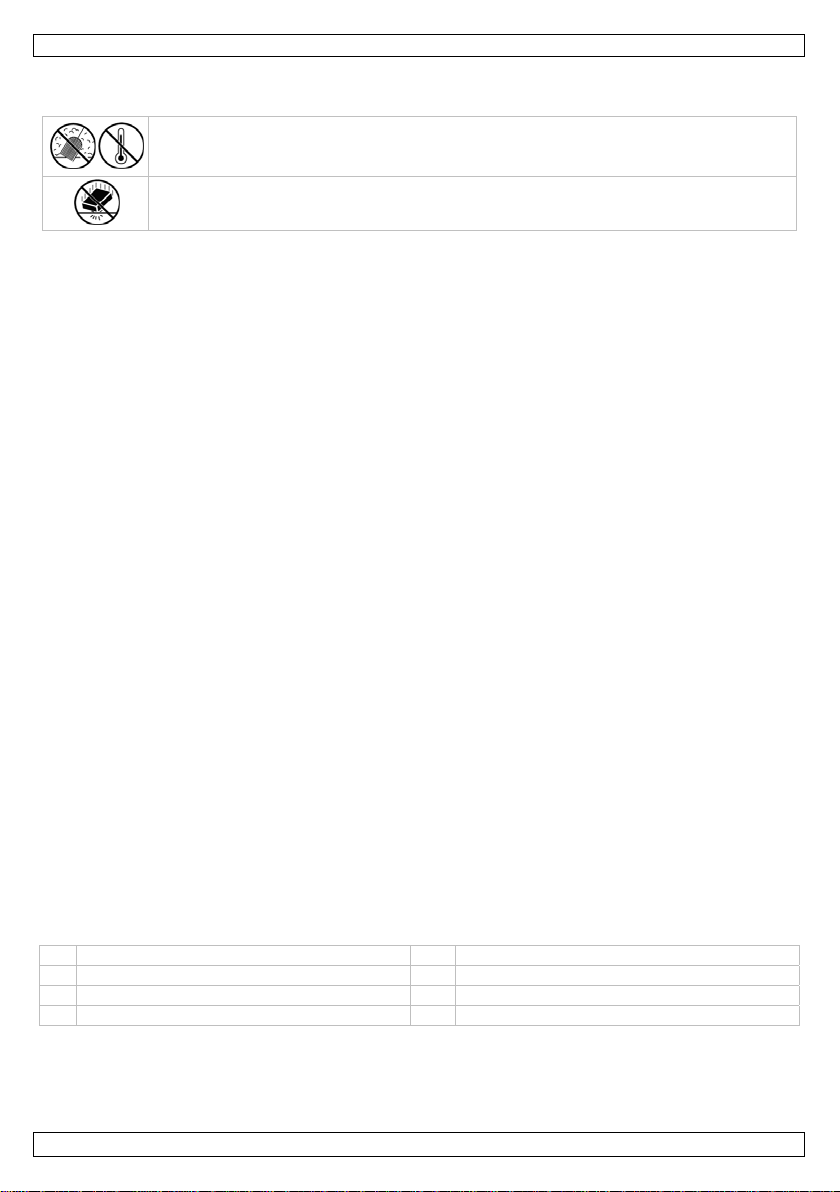
Keep this device away from dust and extreme temperatures. Make sure the ventilation
openings are clear at all times. For sufficient air circulation, leave at least 1” (±2.5 cm) in
front of the openings.
Protect this device from shocks and abuse. Avoid brute force when operating the device.
• Familiarise yourself with the functions of the device before actually using it. Do not allow operation
by unqualified people. Any damage that may occur will most probably be due to unprofessional use
of the device.
• All modifications of the device are forbidden for safety reasons. Damage caused by user modifications
to the device is not covered by the warranty.
• Mechanical wear is not covered by warranty.
• Only use the device for its intended purpose. All other uses may lead to short circuits, burns,
electroshocks, lamp explosion, crash, etc. Using the device in an unauthorised way will void the
warranty.
• Damage caused by disregard of certain guidelines in this manual is not covered by the warranty and
the dealer will not accept responsibility for any ensuing defects or problems.
• A qualified technician should install and service this device.
• Do not switch the device on immediately after it has been exposed to changes in temperature.
Protect the device against damage by leaving it switched off until it has reached room temperature.
• This device is designed for professional use on stage, in discos, theatres, etc. The LX101 can be
used indoors (<35°C, <75%RH) with an alternating current of max. 240V AC/50Hz.
• Lighting effects are not designed for permanent operation: regular operation breaks will prolong their
lives.
• Use the original packaging if the device is to be transported.
• Keep this manual for future reference.
4. Features
• PAR projector with tricoloured LEDs
• extremely slim design
• 3 smooth dimming modes for a perfect colour mixing
• DMX control via max. 9 channels
o 3 channels: RGB
o 4 channels: RGB, dimmer
o 9 channels: RGB, dimmer, colour temperature, shutter, auto, dimming curves
• built-in programs
• double bracket: can be used as a floor spot
• with filter frame, can be used with barndoor (optional): VDLBD56B.
5. Overview
Refer to the illustrations on page 2 of this manual.
1 LCD display 5 power output (PowerCon)
2 DMX output 6 fuse holder
3 DMX input 7 attachment point for safety cable
4 power input (PowerCon) 8 GND
V. 01 – 06/06/2012 4 ©Velleman nv
Page 5

LX101
6. Installation
Refer to the illustrations on page 2 of this manual.
6.1 Overhead mounting
•
Have the device installed by a qualified person, respecting EN 60598-2-17 and all other applicable
norms.
• The construction to which the device is attached should be able to support 10 times the weight of the
device for one hour without deformation.
• The installation must always be secured with a secondary attachment e.g. a safety cable [7].
• Never stand directly below the device when it is being mounted, removed or serviced. Have a
qualified technician check the device once a year and once before you bring it into service.
• Install the device in a location with few passers-by and inaccessible to unauthorised persons.
• Overhead mounting requires extensive experience: calculating workload limits, determining the
installation material to be used… Have the material and the device itself checked regularly. Do not
attempt to install the device yourself if you lack these qualifications as improper installation may
result in serious injuries.
• For truss-mounting, use an appropriate clamp (not incl.) and fit an M10 bolt through the centre of
the (folded) bracket.
• Adjust the desired inclination angle via the mounting bracket and tighten the bracket screws.
6.2 DMX-512 connection
When applicable, connect an XLR cable to the female 3-pin XLR output of a controller (not incl.) and
•
the other side to the male 3-pin XLR input of the LX101. Multiple LX101’s can be linked through
serial linking. The linking cable should be a dual core, screened cable with XLR input and output
connectors.
• Maximum recommended serial data link distance is 500 meters (1640 ft). Maximum recommended
number of fixtures on a serial data link is 32 fixtures.
• A DMX terminator is recommended for installations where the DMX cable has to run a long distance
or is in an electrically noisy environment (e.g. discos). The terminator prevents corruption of the
digital control signal by electrical noise. The DMX terminator is simply an XLR plug with a 120Ω
resistor between pins 2 and 3, which is then plugged into the XLR output socket of the last device in
the chain.
6.3 General
•
Make sure there is no flammable material within a 50cm radius of the device and there is sufficient
cooling.
• Have a qualified electrician carry out the electrical connection.
• First connect the PowerCon plug to the power input [4], and then connect the device to the mains.
• All fixtures must be powered directly off a grounded switched circuit and cannot be run off a rheostat
or dimmer circuit, even if the rheostat or dimmer channel is used solely for 0% to 100% switch.
• The installation has to be approved by an expert before the device is taken into service.
7. Operation
Refer to the illustrations on page 2 of this manual.
7.1 Control Panel Navigation
Access the control panel functions using the four panel buttons located directly underneath the LCD
display.
button function
<MENU> used to access the menu or to return to a previous menu option
<ENTER> used to select and store the current menu or option within the menu
<UP> scrolls through the menu options in ascending order
<DOWN> scrolls through the menu options in descending order
The control panel LCD shows the menu items you select from the menu map. When a menu function is
selected, the display will show immediately the first available option for the selected menu function. To
select a menu item, press <ENTER>.
V. 01 – 06/06/2012 5 ©Velleman nv
Page 6

LX101
Use the <UP> and <DOWN> buttons to navigate the menu map and menu options. Press <ENTER> to
access the menu function currently displayed or to enable a menu option. To return to the previous
option or menu without changing the value, press the <MENU> button.
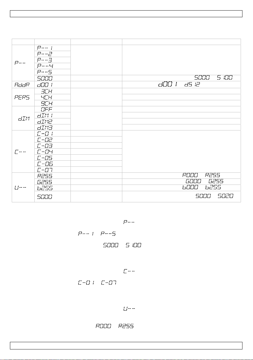
7.2 Menu Functions
menu sub-menu function description
built-in programs select between switching and fading built-in programs
speed set speed of built-in programs ( ~ )
address
channel mode
dimming speed
red
green
blue
cyan
magenta
yellow
white
red custom colour red ( ~ )
green
blue
strobe speed add strobe effect ( ~ )
set DMX address ( ~ )
select 3-channel DMX mode
select 4-channel DMX mode
select 9-channel DMX mode
no dimming speed
fast dimming speed
middle dimming speed
slow dimming speed
select between 7 static colours
custom colour green ( ~ )
custom colour blue ( ~ )
7.3 Stand-Alone Mode
Auto Mode
1. Press <MENU> until is displayed.
2. Press <ENTER> to confirm your selection.
3. Use <UP> or <DOWN> to select the desired program ( ~ ).
4. Press <ENTER> to confirm your selection.
5. Set the speed of built-in programs via <UP> or <DOWN> ( ~ )
6. Press <MODE> to confirm your selection.
Preset Colours
This device has pre-programmed static colours.
1. Press <MENU> until is displayed.
2. Press <ENTER> to confirm your selection.
3. Use <UP> or <DOWN> to select the desired program ( ~ ).
4. Press <ENTER> to confirm your selection.
Custom Static Colours
This device allows you to create custom static colours.
1. Press <MENU> until is displayed.
2. Press <ENTER> to confirm your selection.
3. Use <UP> or <DOWN> to select the desired colour.
4. Press enter to change the red colour value ( ~ , from 0 to 100%).
5. Press <ENTER> to confirm and to move to the next colour (green, blue). Set the value for the
second and third colour.
V. 01 – 06/06/2012 6 ©Velleman nv
Page 7

LX101
6. Press <ENTER> and use <UP> or <DOWN> to set the strobe effect (off) ~ (max.).
7. Finally, press <ENTER> to confirm. Note that you will have selected the first colour. Simply press
<MENU> to exit.
Dimmer speed setting
1. Press <MENU> until is displayed.
2. Press <ENTER> to confirm your selection.
3. Use <UP> or <DOWN> to select the desired dimmer speed ( , ~ ).
4. Press <ENTER> to confirm your selection.
7.4 DMX Mode
This mode allows you to control the fixture by any universal DMX controller.
• All DMX-controlled devices need a digital start address so that the correct device responds to the
signals. This digital start address is the channel number from which the device starts to “listen” to
the DMX controller. The same starting address can be used for a whole group of devices or an
individual address can be set for every device.
• When all devices have the same address, all the units will “listen” to the control signal on one
particular channel. In other words: changing the settings of one channel will affect all devices
simultaneously. If you set individual addresses, each device will “listen” to a separate channel
number. Changing the settings of one channel will only affect the device in question.
o In case of the 3-channel LX101, you will have to set the start address of the first unit to 1
(CH1~3), the second unit to 4 (1 + 3) (CH4~6), the third to 7 (4 + 3) (CH7~9), and so on.
o In case of the 4-channel LX101, you will have to set the start address of the first unit to 1
(CH1~4), the second unit to 5 (1 + 4) (CH5~8), the third to 9 (5 + 4) (CH9~12), and so on.
o In case of the 9-channel LX101, you will have to set the start address of the first unit to 1
(CH1~9), the second unit to 10 (1 + 9) (CH10~18), the third to 19 (10 + 9) (CH19~27), and
1. Press <MENU> until is displayed.
2. Press <ENTER> to confirm your selection.
3. Use <UP> or <DOWN> to set the number of DMX channels ( , or )
4. Press <MENU> until is displayed.
5. Press <ENTER> to confirm your selection.
6. Use <UP> or <DOWN> to select the desired DMX starting address ( ~ ).
DMX Channel Values
9-Channel Mode
so on.
channel function from to description
1 master dimmer 000 255 0 ~ 100%
2 red 000 255
3 green 000 255
0 ~ 100%
(or step time for auto program)
0 ~ 100%
(or fade time for auto program)
4 blue 000 255 0 ~ 100%
000 010 no function
red green blue
011 255 100%
031 050
T
051 070 0% 100%
5 colour macros
071 090 0%
091 110
S
111 130 100% 0%
131 150 100%
151 170
T T
171 200 100% 100% 100%
S
0%
100% 0%
S
T
100%
0% 100%
T
S S
100%
V. 01 – 06/06/2012 7 ©Velleman nv
Page 8

LX101
channel function from to description
white
201 205 3200K
206 210 3400K
211 215 4200K
216 220 4900K
221 225 5600K
226 230 5900K
231 235 6500K
236 240 7200K
241 245 8000K
246 250 8500K
251 255 10 000K
6 strobe
000 009 strobe off
010 255 strobe 0 ~ 20Hz (slow ~ fast)
000 051 no function
052 101 auto program 1
7 auto programs
102 152 auto program 2
153 203 auto program 3
204 254 auto program 4
255 - auto program 5
8 speed 000 255 speed of auto programs (slow ~ fast)
000 051 default dimmer speed
052 101 linear dimmer
9 dimmer
102 152 non-linear dimmer 1
153 203 non-linear dimmer 2
204 255 non-linear dimmer 3
4-Channel Mode
channel function from to description
1 master dimmer 000 255 0 ~ 100%
2 red 000 255 0 ~ 100%
3 green 000 255 0 ~ 100%
4 blue 000 255 0 ~ 100%
3-Channel Mode
channel function from to description
1 red 000 255 0 ~ 100%
2 green 000 255 0 ~ 100%
3 blue 000 255 0 ~ 100%
7.5 Master/Slave Mode
This mode allows control several units simultaneously.
1. Use standard DMX cables to daisy-chain your units together via the DMX connector on the rear of
each fixture. For longer cable runs we suggest using a terminator on the last fixture.
2. Choose the first unit in the chain to function as the master fixture. Press <MENU> and choose a
mode ( , or ).
3. On each of the connected slave units, set the same channel mode as the master (via ).
4. Set the DMX address of all slave units to 1 ( ).
V. 01 – 06/06/2012 8 ©Velleman nv
Page 9

LX101
8. Cleaning and maintenance
• All screws should be tight and free of corrosion.
• The housing, the lenses, the mounting supports and the installation location (e.g. ceiling, suspension,
trussing) should not be deformed, modified or tampered with; e.g. do not drill extra holes in
mounting supports, do not change the location of the connections…
• Mechanically moving parts must not show any signs of wear and tear.
• The electric power supply cables must not show any damage. Have a qualified technician maintain
the device.
• Regularly remove dust from the housing and the air vents using a slightly damp cloth.
• There are no user-serviceable parts inside. Refer to an authorized dealer for service and/or spare
parts.
Fuse Replacement
1. Wedge the fuse holder [6] out of its housing with a flat-head screwdriver.
2. Remove the damaged fuse from its holder and replace with exact same type of fuse.
3. Insert the fuse holder back in its place and reconnect power.
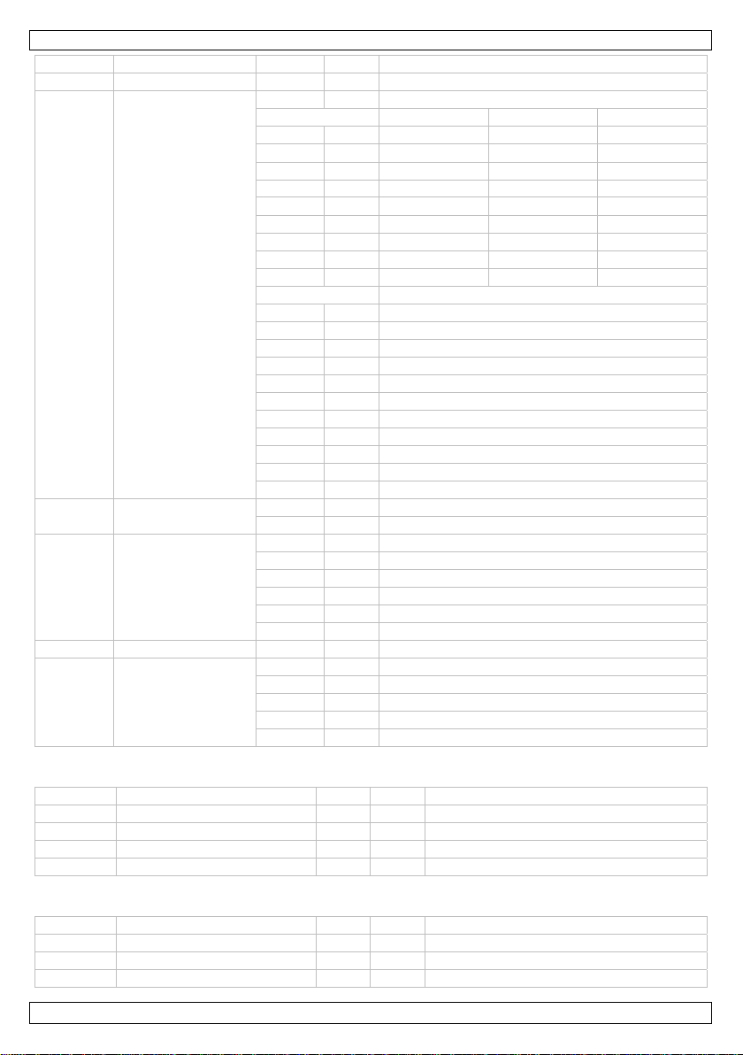
9. Technical Specifications
power supply 240VAC ~ 50Hz
power consumption 45W
light source 18x high-power 3W tri-colour LEDs
beam angle 20°
luminous flux 9600 lm @ 1 m
dimensions 255 x 255 x 80mm
weight 3.5kg
Use this device with original accessories only. Velleman nv cannot be held responsible in the
event of damage or injury resulted from (incorrect) use of this device.
For more info concerning this product and the latest version of this manual, please visit our
website www.luxibel.com.
The information in this manual is subject to change without prior notice.
© COPYRIGHT NOTICE
The copyright to this manual is owned by Velleman nv. All worldwide rights reserved.
No part of this manual may be copied, reproduced, translated or reduced to any electronic medium or
otherwise without the prior written consent of the copyright holder.
V. 01 – 06/06/2012 9 ©Velleman nv
Page 10

0
I
e
e
v
e
V
o
h
d
o
k
a
o
e
v
f
e
t
e
p
n
i
v
k
e
u
k
t
r
e
e
s
m
s
e
m
i
U
v
e
e
n
a
t
e
t
u
n
e
k
r
k
e
s
t
d
c
n
o
0
A
o
k
e
s
s
d
a
u
e
r
c
n
a
w
a
e
e
n
A
D
a
m
o
e
e
e
o
a
e
n
u
g
e
a
v
a
e
e
e
e
n
k
l
s
t
e
c
r
t
o
C
p
n
e
m
n
r
m
r
o
d
e
d
LX1
1
1.
Aan all
Belangr
verwijd
Dank u
toestel b
2.
•
Dit t
gesc
•
De b
han
•
De v
kabe
•
Maa
•
Inst
of st
•
Zorg
opp
•
Zorg
bede
nleiding
ingezetenen
ijke milieu-in
Dit symbool o
weggeworpen
batterijen) ni
terechtkomen
recyclagepun
Hebt u vrag
ring.
oor uw aankoo
schadigd tijde
eiligheids
Wees
dodelij
Trek d
en als
Gebrui
opspat
Houd b
Let op
Kijk ni
•
epi
•
estel valt ond
oolde technicu
eschikbare net
leiding.
edingskabel
l plaatsen.
het toestel va
lleer het toest
ffen.
voor een mini
rvlak.
dat de ventilat
kken.
tijd
•
pe
te voor
Er zijn
reserv
GEBR
an de Europ
ormatie betr
p het toestel of
, dit toestel sch
t bij het gewo
voor recyclage
brengen. Resp
n, contacteer
! Lees deze h
s het transpor
nstructies
oorzichtig bij d
e elektroshock
stekker uit he
het niet gebr
het toestel e
ende vloeistoff
uiten het berei
: dit toestel wo
et rechtstree
lepsieaanvallen
elijke blindheid
manente en on
komen.
geen door de g
onderdelen, co
r bescherming
s moet de elek
panning mag n
ag niet bescha
t met een ges
l op een minim
umafstand va
eopeningen no
IKERSH
se Unie
ffende dit pr
de verpakking
ade kan toebre
e huishoudelij
. U moet dit to
ecteer de plaat
dan de plaat
ndleiding gron
, installeer het
installatie: ra
s te vermijden.
stopcontact (t
ikt.
kel binnensh
n.
van kinderen
dt zeer warm t
s in de lichtb
bij gevoelige p
(flitsblindheid)
herroepelijke s
bruiker verva
ntacteer uw de
klasse I, wat
rische aansluiti
iet hoger zijn d
igd zijn of ing
hikte veiligheid
umafstand van
1 m tussen d
it verstopt zij
NDLEI
duct
geeft aan dat,
ngen aan het
e afval; het m
stel naar uw v
elijke milieuw
elijke autorit
ig voor u het t
dan niet en ra
k geen kabels
rek niet aan de
is. Bescherm t
n onbevoegde
ijdens het gebr
on om
ersonen
hade aan de o
gbare onderdel
ler.
il zeggen dat h
ng verzorgen.
n de spanning
kort worden. L
skabel (bv. VD
0,5 m van ont
lichtuitgang v
. U mag het to
ING
ls het na zijn l
ilieu. Gooi dit t
et bij een gesp
rdeler of naar
tgeving.
iten betreffe
estel in gebrui
dpleeg uw dea
aan die onder
kabel!) voorda
gen regen, vo
.
ik.
en
en in dit toeste
t toestel geaa
in de specifica
at uw dealer z
LSC7 of VDLS
lambare en ex
n het toestel e
stel nooit ged
venscyclus wo
oestel (en eve
cialiseerd bed
en lokaal
d de
neemt. Werd
er.
troom staan o
u het toestel
htigheid en
l. Voor onderh
d moet zijn. Ee
ies achteraan
nodig een nie
8).
losieve voorw
het belichte
eltelijk of volle
rdt
tuele
ijf
het
einigt
ud of
n
e
uwe
rpen
ig
V. 01 –
6/06/2012
10
©Velle
an nv
Page 11

LX101
r
3. Algemene richtlijnen
Raadpleeg de Velleman® service- en kwaliteitsgarantie achteraan deze handleiding.
Bescherm tegen stof en extreme tempe
verstopt geraken. Voorzie een ruimte van minstens 2,5 cm tussen het toestel en elk ander
object.
Bescherm tegen schokken. Vermijd brute kracht tijdens de bediening.
aturen. Zorg dat de verluchtingsopeningen niet
• Leer eerst de functies van het toestel kennen voor u het gaat gebruiken. Ongeschoolde personen
mogen dit toestel niet gebruiken. Meestal is beschadiging het gevolg van onprofessioneel gebruik.
• Om veiligheidsredenen mag u geen wijzigingen aanbrengen. Schade door wijzigingen die de
gebruiker heeft aangebracht valt niet onder de garantie.
• Mechanische slijtage valt niet onder de garantie.
• Gebruik het toestel enkel waarvoor het gemaakt is. Andere toepassingen kunnen leiden tot
kortsluitingen, brandwonden, elektrische schokken, enz. Bij onoordeelkundig gebruik vervalt de
garantie.
• De garantie geldt niet voor schade door het negeren van bepaalde richtlijnen in deze handleiding en
uw dealer zal de verantwoordelijkheid afwijzen voor defecten of problemen die hier rechtstreeks
verband mee houden.
• Laat dit toestel installeren en onderhouden door een geschoolde technicus.
• Om beschadiging te vermijden, zet u het toestel best niet aan onmiddellijk nadat het werd blootgesteld
aan temperatuurschommelingen. Wacht tot het toestel op kamertemperatuur gekomen is.
• Dit toestel is ontworpen voor professioneel gebruik op podia, in disco's, enz. U mag dit toestel enkel
binnenshuis gebruiken (<35°C, <75%RH). Sluit aan op 240 VAC/50 Hz.
• Lichteffecten zijn niet ontworpen voor continue werking: regelmatige onderbrekingen doen ze langer
meegaan.
• Gebruik de oorspronkelijke verpakking wanneer u het toestel vervoert.
• Bewaar deze handleiding voor verdere raadpleging.
4. Eigenschappen
• PAR-projector met driekleurige leds
• zeer smal design
• 3 vloeiende dimfuncties voor een perfecte kleurenmenging
• DMX-sturing via max. 9 kanalen
o 3 kanalen: RGB
o 4 kanalen: RGB, dimmer
o 9 kanalen: RGB, dimmer, kleurtemperatuur, sluiter, auto, dimcurves
• ingebouwde programma's
• dubbele beugel: geschikt voor gebruik als vloerspot
• met filterframe, kan gebruikt worden met barndoor (optioneel): VDLBD56B.
5. Omschrijving
Raadpleeg de afbeeldingen op pagina 2 van deze handleiding.
1 lcd-display 5 voedingsuitgang (PowerCon)
2 DMX-uitgang 6 zekeringhouder
3 DMX-ingang 7 bevestiging veiligheidskabel
4 voedingsingang (PowerCon) 8 GND-aansluiting
V. 01 – 06/06/2012 11 ©Velleman nv
Page 12

LX101
6. Installatie
Raadpleeg de afbeeldingen op pagina 2 van deze handleiding.
6.1 Het toestel monteren
•
Laat een geschoolde technicus dit toestel installeren conform EN 60598-2-17 en andere toepasselijke
normen.
• De constructie waaraan het toestel wordt bevestigd, moet gedurende 1 uur 10 x het gewicht van dit
toestel kunnen dragen zonder te vervormen.
• Maak het toestel ook vast met een veiligheidskabel [7].
• Sta nooit recht onder het toestel wanneer u het monteert, verwijdert of schoonveegt. Laat het toestel
controleren door een geschoolde technicus voor u het in gebruik neemt en laat het 1 x per jaar
volledig nakijken.
• Installeer dit toestel op een plaats waar niemand langs moet lopen, kan neerzitten of het toestel kan
aanraken.
• Een degelijke praktijkervaring is vereist voor de plaatsing van dit toestel. U moet de
maximumbelasting van de draagconstructie kunnen berekenen, weten welk constructiemateriaal u
kunt gebruiken en u moet het gebruikte materiaal en het toestel af en toe laten nakijken. Monteer
het toestel niet zelf indien u er geen ervaring mee heeft. Een slechte montage kan leiden tot
verwondingen.
• Regel de gewenste invalshoek door middel van de montagebeugel en draai de regelschroeven stevig
aan.
• Een geschoolde elektricien moet het toestel aansluiten.
• Sluit het toestel via de stekker aan op het lichtnet. Sluit het niet aan op een dimmerpack.
6.2 DMX512-aansluiting
Raadpleeg de figuren op pagina 2 van deze handleiding.
• Indien van toepassing, sluit een XLR-kabel aan de vrouwelijke 3-pin XLR-uitgang van een controller
(niet meegelev.) en de andere kant van de mannelijke 3-pin XLR-ingang van de LX101. U kunt
verscheidene LX101’s aan elkaar koppelen met behulp van een seriële koppeling. Gebruik daarvoor
een 2-aderige afgeschermde kabel met XLR ingang- en uitgangsaansluitingen.
• De maximaal aanbevolen kabellengte is 500 meter, het aanbevolen maximumaantal toestellen op
eenzelfde aansluiting is 32.
• Een DMX eindweerstand is aanbevolen als de DMX-kabel vrij lang is of wordt gebruikt in een
omgeving met veel elektrische ruis (bv. een discotheek). De eindweerstand voorkomt corruptie van
het digitale controlesignaal door elektrische ruis. De DMX eindweerstand is niets meer dan een XLRstekker met een weerstand van 120 Ω van pin 2 naar 3. Deze XLR-stekker wordt dan aangesloten op
de XLR-uitgang van het laatste toestel in de reeks.
6.3 Algemeen
•
Verwijder alle brandbaar materiaal in een straal van 0,5 m rond het toestel en voorzie voldoende
koeling.
• Een geschoolde elektricien moet het toestel aansluiten.
• Steek eerst de PowerCon-stekker in de ingang [4] en koppel het toestel aan het lichtnet.
• Alle toestellen moet via een geaard stopcontact gevoed worden en mogen niet via een variabele
weerstand of dimcircuit gevoed worden, ook al gebruikt u de variabele weerstand of het dimcircuit
als een 0% tot 100% inschakeling.
• De installatie moet voor het eerste gebruik gekeurd worden door een expert.
7. Gebruik
Raadpleeg de afbeeldingen op pagina 2 van deze handleiding.
7.1 Het bedieningspaneel
Bedien het paneel met behulp van de vier toetsen onderaan de lcd-display.
toets functie
<MENU> toegang tot het menu of terugkeer naar het vorige menu
ENTER> selectie en bevestiging van een optie
V. 01 – 06/06/2012 12 ©Velleman nv
Page 13

LX101
toets functie
<UP> scroll door de verschillende menuopties in stijgende volgorde
<DOWN>< scroll door de verschillende menuopties in dalende volgorde
De geselecteerde menufunctie wordt op de lcd-display weergegeven. De lcd-display geeft ook de
eerstvolgende menuoptie onder de functie weer. Selecteer een menuoptie met <ENTER>.
Scroll doorheen het menu met <UP> en <DOWN>. Selecteer de menufunctie met <ENTER> en druk op
<MENU> om naar het hoofdmenu terug te keren zonder de waarde te hebben gewijzigd.
7.2 Menufuncties
menu submenu functie omschrijving
interne programma’s
interne programma’s met plotselinge of geleidelijke
overgang
snelheid
adres
kanaalmodus
dimsnelheid
rood
groen
blauw
cyaan
magenta
geel
wit
rood schakering rood ( ~ )
groen
blauw
stroboscoopsnelheid stroboscoopeffect ( ~ )
snelheid van interne programma’s
( ~ )
DMX-adres ( ~ )
3-kanaals DMX-sturing
44-kanaals DMX-sturing
9-kanaals DMX-sturing
geen dimsnelheid
hoge snelheid
gemiddelde snelheid
lage snelheid
kies tussen 7 statische kleuren
schakering groen ( ~ )
schakering blauw ( ~ )
7.3 Standalone
Automatische sturing
1. Druk op <MENU> tot op de lcd-display verschijnt.
2. Bevestig uw keuze met <ENTER>.
3. Kies het gewenste programma ( ~ ) met <UP> en <DOWN>.
4. Bevestig uw keuze met <ENTER>.
5. Stel de snelheid van de interne programma’s in met <UP> of <DOWN> ( ~ ).
6. Druk op <MODE> om te bevestigen.
Interne kleuren
Deze projector heeft een reeks statische presetkleuren.
1. Druk op <MENU> tot op de lcd-display verschijnt.
2. Bevestig uw keuze met <ENTER>.
3. Kies het gewenste programma ( ~ ) met <UP> en <DOWN>.
4. Bevestig uw keuze met <ENTER>.
V. 01 – 06/06/2012 13 ©Velleman nv
Page 14

LX101
Aanmaken van een statische kleur
Met deze projector kunt u zelf kleuren aanmaken.
1. Druk op <MENU> tot op de lcd-display verschijnt.
2. Bevestig uw keuze met <ENTER>.
3. Selecteer de gewenste kleur met <UP> of <DOWN>.
4. Wijzig de kleurwaarde met <ENTER> ( ~ , van 0 tot 100%).
5. Bevestig uw keuze en ga naar de volgende kleur (groen, blauw) met <ENTER>. Geef nu ook de
waarde voor de twee volgende kleuren in.
6. Druk op <ENTER> en stel het stroboscoopeffect in met <UP> of <DOWN> ( (uit) ~
(max.)).
7. Bevestig vervolgens met <ENTER>. De eerste kleur is opnieuw geselecteerd. Druk op <MENU> om
het menu te verlaten.
Dimmer speed setting
1. Druk op <MENU> tot op de display verschijnt.
2. Bevestig uw keuze met <ENTER>.
3. Kies de gewenste dimsnelheid met <UP> of <DOWN> ( , ~ ).
4. Bevestig uw keuze met <ENTER>.
7.4 DMX-sturing
Sturing van het toestel via een universele DMX-controller.
• Alle DMX-gestuurde toestellen hebben een digitaal startadres nodig, zodat het juiste toestel reageert
op de signalen. Dit digitale startadres is het kanaalnummer van waarop het toestel ‘luistert’ naar het
signaal van de DMX controller. U kunt één enkel startadres gebruiken voor een groep toestellen of u
kunt per toestel een nieuw startadres ingeven.
• Wanneer u een enkel startadres instelt, zullen alle toestellen ‘luisteren’ naar hetzelfde kanaal. Met
andere woorden: wanneer u de instellingen voor 1 kanaal verandert, zullen alle toestellen er tegelijk
op reageren. Wanneer u verschillende adressen instelt, dan luistert elk toestel naar een ander
kanaal. Met andere woorden: wanneer u de instellingen van een kanaal verandert, zal enkel het
toestel op dat kanaal reageren.
o In het geval van de 3-kanaals LX101, zult u het startadres van het eerste toestel op 1
(CH1~3) moeten instellen, van het tweede toestel op 4 (1 + 3) (CH4~6), van het derde op 7
(4 + 3) (CH7~9), enz.
o In het geval van de 4-kanaals LX101, zult u het startadres van het eerste toestel op 1
(CH1~4) moeten instellen, van het tweede toestel op 5 (1 + 4) (CH5~8), van het derde op 9
(5 + 4) (CH9~12), enz.
o In het geval van de 9-kanaals LX101, zult u het startadres van het eerste toestel op 1
(CH1~9) moeten instellen, van het tweede toestel op 10 (1 + 9) (CH10~18), van het derde op
1. Druk op <MENU> tot op de lcd-display verschijnt.
2. Bevestig uw keuze met <ENTER>.
3. Kies het aantal DMX-kanalen met <UP> of <DOWN> ( , of )
4. Druk op <MENU> tot op de lcd-display verschijnt.
5. Bevestig uw keuze met <ENTER>.
6. Kies het DMX-startadres met <UP> of <DOWN> ( ~ ).
DMX-waarden per kanaal
9-kanaalsmodus
19 (10 + 9) (CH19~27), enz.
kanaal functie van tot omschrijving
1 masterdimmer 000 255 0 ~ 100%
2 rood 000 255
3 groen 000 255
0 ~ 100%
(of stapduur voor automatisch programma)
0 ~ 100%
(of fadeduur voor automatisch programma)
V. 01 – 06/06/2012 14 ©Velleman nv
Page 15
LX101
kanaal functie van tot omschrijving
4 blauw 000 255 0 ~ 100%
000 010 geen functie
rood groen blauw
011 255 100%
031 050
T
051 070 0% 100%
071 090 0%
091 110
S
111 130 100% 0%
131 150 100%
151 170
T T
S
0%
100% 0%
S
T
100%
0% 100%
T
S S
100%
171 200 100% 100% 100%
5 kleurenmacro’s
wit
201 205 3200K
206 210 3400K
211 215 4200K
216 220 4900K
221 225 5600K
226 230 5900K
231 235 6500K
236 240 7200K
241 245 8000K
246 250 8500K
251 255 10 000K
6 stroboscoop
000 009 stroboscoop uit
010 255 stroboscoop 0 ~20Hz (traag ~ snel)
000 051 geen functie
052 101 automatisch programma 1
7
automatische
programma’s
102 152 automatisch programma 2
153 203 automatisch programma 3
204 254 automatisch programma 4
255 - automatisch programma 5
8 snelheid 000 255 snelheid automatisch programma (traag ~ snel)
000 051 standaard dimsnelheid
052 101 lineaire dimmer
9 dimmer
102 152 niet-lineaire dimmer 1
153 203 niet-lineaire dimmer 2
204 255 niet-lineaire dimmer 3
4-kanaalsmodus
kanaal functie van tot omschrijving
1 masterdimmer 000 255 0 ~ 100%
2 rood 000 255 0 ~ 100%
3 groen 000 255 0 ~ 100%
4 blauw 000 255 0 ~ 100%
3-kanaalsmodus
kanaal functie van tot omschrijving
1 rood 000 255 0 ~ 100%
2 groen 000 255 0 ~ 100%
3 blauw 000 255 0 ~ 100%
V. 01 – 06/06/2012 15 ©Velleman nv
Page 16

LX101
7.5 Master-slavesturing
Simultane sturing van meerdere toestellen.
1. Koppel uw toestellen aan elkaar met behulp van standaard DMX-kabels. Gebruik een eindweerstand
op het laatste toestel bij langere kabellengtes.
2. Kies het eerste toestel in de reeks als mastertoestel. Druk op <MENU> en kies een aanstuurmodus
( , of ).
3. Kies dezelfde kanaalmodus op elk slavetoestel als die van het mastertoestel (via ).
4. Stel het DMX-adres van alle slavetoestellen op 1 ( ).
8. Reiniging en onderhoud
• Alle gebruikte schroeven moeten goed zijn aangespannen en mogen geen sporen van roest vertonen.
• De behuizing, de lenzen, de montagebeugels en de montageplaats (bv. het plafond of het gebinte)
mogen niet vervormd zijn of aangepast worden (geen extra gaten in montagebeugels, aansluitingen
niet verplaatsen etc.)
• Mechanisch bewegende delen mogen geen sporen van slijtage vertonen en mogen niet onregelmatig
bewegen.
• De voedingskabels mogen niet beschadigd zijn. Laat het toestel onderhouden door een geschoolde
technicus.
• Verwijder regelmatig het stof van de behuizing en de ventilatieopeningen met een vochtige doek.
• U mag geen onderdelen vervangen. Raadpleeg uw erkende verdeler voor eventuele
reserveonderdelen.
De zekering vervangen
1. Maak de zekeringhouder [6] los met behulp van een schroevendraaier met platte punt.
2. Verwijder de oude zekering en vervang door een zekering van hetzelfde type.
3. Plaats de zekeringhouder terug in het toestel en koppel het toestel aan het lichtnet.
9. Technische specificaties
voeding 240VAC ~ 50Hz
verbruik 45W
lichtbron 18 driekleurige, high-power leds van 3W
stralingshoek 20°
lichtstroom 9600 lm @ 1 m
afmetingen 255 x 255 x 80mm
gewicht 3.5kg
Gebruik dit toestel enkel met originele accessoires. Velleman nv is niet aansprakelijk voor
schade of kwetsuren bij (verkeerd) gebruik van dit toestel.
Voor meer informatie over dit product en de laatste versie van deze handleiding, zie
www.luxibel.com.
De informatie in deze handleiding kan te allen tijde worden gewijzigd zonder voorafgaande
kennisgeving.
© AUTEURSRECHT
Velleman nv heeft het auteursrecht voor deze handleiding. Alle wereldwijde rechten
voorbehouden.
Het is niet toegestaan om deze handleiding of gedeelten ervan over te nemen, te kopiëren, te vertalen,
te bewerken en op te slaan op een elektronisch medium zonder voorafgaande schriftelijke toestemming
van de rechthebbende.
V. 01 – 06/06/2012 16 ©Velleman nv
Page 17

0
I
i
o
d
u
l
u
C
a
e
e
c
â
u
r
a
o
a
o
i
i
u
p
q
a
e
c
d
Ê
u
c
c
s
v
e
i
e
d
à
n
l
M
n
e
t
e
a
g
é
s
n
é
d
e
e
m
m
p
a
s
s
m
a
0
E
s
u
n
m
é
e
u
b
i
s
o
g
r
c
s
c
n
t
i
o
n
v
s
s
n
é
e
m
a
o
S
e
e
o
d
u
o
u
e
é
p
t
t
o
a
e
m
v
p
e
i
e
e
e
e
e
d
n
r
LX1
1
1.
Aux rés
Des inf
En cas
Nous vo
l’apparei
revende
2.
•
Cet
Un t
•
La t
noti
•
Le c
reno
•
Fixe
•
Inst
expl
•
Resp
•
Ne j
ntroducti
dents de l'Un
rmations env
Ce symbole s
peut polluer l'
éventuelles)
l’appareil en
recyclage loc
l’environnem
e questions,
s remercions d
. Si l’appareil a
r.
onsignes
tre pr
électro
Débran
débran
Utiliser
project
Garder
Attent
Ne pa
•
de
•
ppareil ressort
chnicien qualif
nsion réseau n
e.
ble d’alimentat
veler le câble
l’appareil à l’ai
ller le LX101
sif.
ecter une dista
mais obstruer
d’a
•
d’e
Il n’y a
éventu
n
on européen
ronnemental
r l'appareil ou
environnement
armi les déche
uestion. Renvo
l. Il convient d
nt.
ontacter les
e votre achat !
été endomma
e sécurit
dent lors de l’i
hocs mortels.
cher l’appareil
her l'appareil ;
cet appareil u
ions d’eau.
hors de la port
ion : le boîtier
regarder dir
crise d’épilepsi
euglement te
ndommagemen
aucune pièce
lles chez votre
à la classe de
é doit établir la
peut pas dép
ion ne peut pa
’alimentation
de d’un câble d
une distance
ce minimum d
es fentes d’aér
ODE D’
e
s importante
l'emballage ind
. Ne pas jeter
s municipaux
yer les équipe
respecter la r
utorités local
Lire la présent
é pendant le tr
nstallation : to
’il n’est pas uti
non pas le câ
iquement à l'
e des enfants
u spot chauffe
ctement dan
chez les pers
poraire (aveu
t permanent et
aintenable pa
revendeur.
rotection I, ce
connexion éle
sser la tension
être replissé o
i nécessaire.
e sécurité adéq
inimale de 0,5
e 1 m entre la
tion. Éviter de
MPLOI
concernant
ique que l’élimi
n appareil élec
on sujets au tr
ents usagés à
glementation l
es pour élimi
notice attenti
ansport, ne pa
cher un câble
lisé ou pour le
le.
ntérieur. Prot
et des personn
pendant l’usag
la source lu
nnes sujettes
lement par écl
irréversible de
l’utilisateur. C
qui implique qu
trique.
mentionnée da
u endommagé.
uat (p.ex. VDL
m de tout obj
ortie lumière d
couvrir, entièr
e produit
ation d’un app
rique ou électr
sélectif ; une
votre fournisse
cale relative à
ation.
ement avant la
l’installer et c
ous tension pe
ettoyer. Tirer l
ger de la pluie
s non autorisé
e.
ineuse afin d’
ir)
l’œil.
mmander des
e l’appareil doi
ns les spécifica
Demander à v
C7 ou VDLSC
t ou produit inf
e l’appareil et l
ment ou parti
areil en fin de
nique (et des
échèterie trait
r ou à un serv
la protection d
mise en servic
nsulter votre
t causer des
a fiche pour
, de l’humidité
s.
viter les risqu
ièces de recha
être mis à la t
ions à la fin de
tre revendeur
8).
lammable ou
surface illumi
llement, l’appa
ie
iles
ra
ce de
de
t des
s
nge
rre.
cette
e
ée.
eil.
V. 01 –
6/06/2012
17
©Velle
an nv
Page 18
LX101
3. Directives générales
Se référer à la garantie de service et de qualité Velleman® en fin de notice.
Protéger contre la poussière. Protéger contre la chaleur extrême. Veiller à ce que les
fentes de ventilation ne soient pas bloquées. Laisser une distance de minimum 2,5 cm
entre l’appareil et tout autre objet.
Protéger contre les chocs et le traiter avec circonspection pendant l’opération.
• Se familiariser avec le fonctionnement de l’appareil avant de l’utiliser. Ne pas permettre pas aux
personnes non qualifiées d’opérer cet appareil. La plupart des dégâts sont causés par un usage non
professionnel.
• Toute modification est interdite pour des raisons de sécurité. Les dommages occasionnés par des
modifications par le client ne tombent pas sous la garantie.
• L’usure mécanique ne tombe pas sous la garantie.
• N’utiliser votre LX101 qu’à sa fonction prévue. Tout autre usage peut causer des courts-circuits, des
brûlures, des électrochocs, etc. Un usage impropre annule d'office la garantie.
• La garantie ne s’applique pas aux dommages survenus en négligeant certaines directives de cette
notice et votre revendeur déclinera toute responsabilité pour les problèmes et les défauts qui en
résultent.
• Confier l’installation et l’entretien à un personnel qualifié.
• Ne pas brancher l’appareil après exposition à des variations de température. Afin d’éviter des
dommages, attendre jusqu’à ce que l’appareil ait atteint la température ambiante avant de l’utiliser.
• Cet appareil a été développé pour usage professionnel dans des discothèques, des théâtres, etc.
N’utiliser cet appareil qu’à l’intérieur (<35°C, <75°RH). Le raccorder à une source de courant CA de
240 VCA/50 Hz.
• Un effet lumineux n’est pas conçu pour une opération continue. Des pauses régulières prolongeront
sa vie.
• Transporter l’appareil dans son emballage originel.
• Garder cette notice pour toute référence ultérieure.
4. Caractéristiques
• projecteur PAR à LED tricolores
• design ultraplat
• 3 modes de variation fluides pour un mixage de couleurs parfait
• pilotage DMX depuis max. 9 canaux
o 3 canaux : RVB
o 4 canaux : RVB, variation
o 9 canaux : RVB, variation, température de couleur, obturateur, auto, courbes de variation
• programmes intégrés
• double étrier : peut être monté sur le sol
• avec porte-filtre, peut être utilisé avec coupe-flux (optionnel) : VDLBD56B.
5. Description
Se référer aux illustrations en page 2 de ce mode d’emploi.
1 afficheur LCD 5 sortie d’alimentation (PowerCon)
2 sortie DMX 6 porte-fusible
3 entrée DMX 7 attache pour câble de sécurité
4 entrée d’alimentation (PowerCon) 8 connexion GND
V. 01 – 06/06/2012 18 ©Velleman nv
Page 19

LX101
6. Installation
Se référer aux illustrations en page 2 de ce mode d’emploi.
6.1 Montage de l’appareil
•
Un technicien qualifié doit installer l’appareil en respectant EN 60598-2-17 et toute autre norme
applicable.
• La construction portante de l’appareil doit être capable de supporter 10 x le poids de l’appareil
pendant une heure, sans qu’une déformation de la construction en résulte.
• Fixer votre LX101 à l’aide d’un câble de sécurité [7] (sécurité supplémentaire).
• Éviter de vous positionner en dessous de l’appareil pour l’enlever ou lors du montage ou du
nettoyage. Un technicien qualifié doit réviser l’appareil avant la mise en service. Organiser une
révision minutieuse annuelle.
• Installer l’appareil à un endroit où personne ne peut passer ou s’asseoir et où personne ne peut le
toucher.
• L’installation de cet appareil exige une solide expérience pratique : le calcul de la charge max. de la
construction, les matériaux d’installation requis etc. De temps en temps, un technicien qualifié doit
vérifier la construction portante et l’appareil même. Ne pas essayer d’installer cet appareil vousmême si vous n’avez pas les qualifications requises ; une installation incorrecte peut entraîner des
blessures.
• Déterminer l’angle d’inclinaison au moyen de l’étrier de montage et serrer les vis de montage.
• Un électricien qualifié doit établir la connexion électrique.
• Brancher l’appareil sur le réseau électrique par la fiche d’alimentation. Ne pas le brancher sur un bloc
de puissance.
6.2 Connexion DMX512
•
Si nécessaire, connecter un câble à fiche XLR à la sortie XLR femelle à 3 broches de votre contrôleur
(non incl.) et l’autre fiche XLR mâle à 3 broches à l’entrée du LX101. Il est possible de relier
plusieurs LX101 à partir d’une connexion sérielle. Utiliser un câble de connexion blindé à 2
conducteurs avec des connecteurs d’entrée et de sortie XLR.
• Longueur maximale de la connexion : 500 mètres. Nombre maximal d’unités sur une connexion
sérielle : 32.
• Une résistance de terminaison DMX est à recommander si le câble DMX doit couvrir une grande
distance ou s’il est utilisé dans un environnement avec beaucoup de bruit électrique (p.ex. une
discothèque). La résistance de terminaison prévient la corruption du signal de contrôle numérique
par le bruit électrique. La résistance de terminaison DMX n’est rien d’autre qu’une fiche XLR avec une
résistance de 120 Ω de broche 2 vers broche 3 (voir illustration à gauche). Cette fiche XLR est
connectée à la sortie XLR du dernier appareil de la série.
6.3 En général
•
Enlever tout matériau inflammable dans un rayon de 0,5 m autour de l’appareil et assurer une
ventilation suffisante.
• Un électricien qualifié doit établir la connexion électrique.
• Insérer la fiche PowerCon dans l’entrée [4] et connecter l’appareil au réseau électrique.
• Tout projecteur doit être branché sur une prise de courant mise à la terre et ne peut pas être
alimenté depuis un rhéostat ou un circuit variateur, même si le rhéostat ou le circuit variateur est
utilisé comme un interrupteur marche/arrêt (de 0% à 100%).
• Un expert doit approuver l’installation avant qu’elle puisse être prise en service.
7. Emploi
Se référer aux illustrations en page 2 de ce mode d’emploi.
7.1 Navigation dans le menu
Accéder aux fonctions en utilisant les touches au bas de l’afficheur LCD.
touche fonction
<MENU> accès au menu ou retour vers le niveau précédent
<ENTER> sélection et sauvegarde d’une option
V. 01 – 06/06/2012 19 ©Velleman nv
Page 20

LX101
touche fonction
<UP> défilement du menu de bas en haut
<DOWN> défilement du menu de haut en bas
L’afficheur LCD affiche les fonctions ainsi que la première option disponible dans la fonction sélectionnée.
Enfoncer la touche <ENTER> pour sélectionner une fonction.
Faire défiler le menu avec les touches <UP> et <DOWN>. Enfoncer la touche <ENTER> pour accéder à la
fonction sélectionnée ou enfoncer la touche <MENU> pour revenir au niveau précédent.
7.2 Fonctions du menu
menu sous-menu fonction description
programme interne sélection effet à transition subite ou graduelle
vitesse
adresse
mode canal
vitesse de variation
rouge
vert
bleu
cyan
magenta
jaune
blanc
rouge
vert personnalisation vert ( ~ )
bleu
vitesse stroboscope
vitesse de l’effet interne ( ~ )
adressage DMX ( ~ )
sélection mode DMX 3 canaux
sélection mode DMX 4 canaux
sélection mode DMX 9 canaux
pas de vitesse de variation
vitesse de variation élevée
vitesse de variation moyenne
vitesse de variation basse
sélectionner une des 7 couleurs statiques
personnalisation rouge ( ~ )
personnalisation bleu ( ~ )
ajout effet stroboscopique ( ~ )
7.3 Mode autonome
Pilotage automatique
1. Enfoncer la touche <MENU> jusqu’à ce que s’affiche.
2. Confirmer votre sélection avec la touche <ENTER>.
3. Sélectionner le programme ( ~ ) avec les touches <UP> et <DOWN>.
4. Confirmer votre sélection avec la touche <ENTER>.
5. Sélectionner la vitesse de variation ( ~ ) avec les touches <UP> et <DOWN>.
6. Confirmer votre sélection avec la touche <MODE>.
Couleurs préprogrammées
Ce projecteur intègre une série de couleurs statiques préprogrammées.
1. Enfoncer la touche <MENU> jusqu’à ce que s’affiche.
2. Confirmer votre sélection avec la touche <ENTER>.
3. Sélectionner le programme ( ~ ) avec les touches <UP> et <DOWN>.
4. Confirmer votre sélection avec la touche <ENTER>.
V. 01 – 06/06/2012 20 ©Velleman nv
Page 21

LX101
Couleurs statiques personnalisées
Ce projecteur vous permet de créer vos propres couleurs.
1. Enfoncer la touche <MENU> jusqu’à ce que s’affiche.
2. Confirmer votre sélection avec la touche <ENTER >.
3. Sélectionner la couleur avec les touches <UP> et <DOWN>.
4. Modifier la valeur de la couleur rouge ( ~ , de 0 à 100%).
5. Confirmer et sélectionner la deuxième couleur (vert, bleu) avec <ENTER>. Configurer la valeur de la
deuxième et troisième couleur.
6. Enfoncer <ENTER> et configurer l’effet stroboscopique ( (éteint) ~ (max.)) avec les
touches <UP> et <DOWN>.
7. Enfin, confirmer avec <ENTER>. La première couleur sera sélectionnée. Quitter le menu avec la
touche <MENU>.
Vitesse de variation
1. Enfoncer <MENU> jusqu’à ce que s’affiche.
2. Confirmer votre sélection avec la touche <ENTER>.
3. Sélectionner la vitesse de variation ( , ~ ) avec les touches <UP> et
<DOWN>.
4. Confirmer votre sélection avec la touche <ENTER>.
7.4 Mode de pilotage DMX
Ce mode permet de piloter votre projecteur sans contrôleur DMX.
• Tous les appareils pilotés par un signal DMX demandent une adresse de départ DMX pour assurer
que les appareils corrects réagissent sur les signaux de contrôle. Cette adresse de départ numérique
indique le numéro de canal sur lequel l’appareil écoute le contrôleur DMX. Vous avez le choix entre
une seule adresse de départ pour toute une série d’appareils ou une adresse de départ par appareil.
• Dans le cas d’une seule adresse, tous les appareils « écouteront » les mêmes signaux, sur un seul
canal. Tous les appareils seront donc influencés lorsque vous changez les réglages d’un seul canal.
Avec des adresses de départ individuelles, chaque appareil « écoutera » son propre canal. Par
conséquent, un ajustement des réglages d’un canal n’influence que l'appareil sur ce canal.
o Pour le LX101 à 3 canaux, l’adresse de départ du premier appareil est 1 (CH1~3), du
deuxième 4 (1 + 3) (CH4~6), du troisième 7 (4 + 3) (CH7~9), etc.
o Pour le LX101 à 4 canaux, l’adresse de départ du premier appareil est 1 (CH1~4), du
deuxième 5 (1 + 4) (CH5~8), du troisième 9 (5 + 4) (CH9~12), etc.
o Pour le LX101 à 9 canaux, l’adresse de départ du premier appareil est 1 (CH1~9), du
1. Enfoncer la touche <MENU> jusqu’à ce que s’affiche.
2. Confirmer votre sélection avec la touche <ENTER>.
3. Configurer le nombre de canaux DMX ( , or ) avec les touches <UP> et
4. Enfoncer <MENU> jusqu’à ce que s’affiche.
5. Confirmer votre sélection avec la touche <ENTER>.
6. Sélectionner l’adresse DMX ( ~ ) avec les touches <UP> et <DOWN>.
Valeurs DMX par canal
Mode 9 canaux
deuxième 10 (1 + 9) (CH10~18), du troisième 19 (10 + 9) (CH19~27), etc.
<DOWN>.
canal fonction de à description
1 variateur maître 000 255 0 ~ 100%
rouge
2
vert
3
000 255
000 255
0 ~ 100%
(ou durée d’étape pour programme automatique)
0 ~ 100%
(ou durée de variation pour programme automatique)
4 bleu 000 255 0 ~ 100%
V. 01 – 06/06/2012 21 ©Velleman nv
Page 22

LX101
canal fonction de à description
000 010 pas de fonction
rouge vert bleu
011 255 100%
031 050
T
051 070 0% 100%
071 090 0%
091 110
S
111 130 100% 0%
131 150 100%
151 170
T T
S
0%
100% 0%
S
T
100%
0% 100%
T
S S
100%
171 200 100% 100% 100%
5 macros couleur
blanc
201 205 3200K
206 210 3400K
211 215 4200K
216 220 4900K
221 225 5600K
226 230 5900K
231 235 6500K
236 240 7200K
241 245 8000K
246 250 8500K
251 255 10 000K
6 stroboscope
000 009 stroboscope éteint
010 255 stroboscope 0 ~20Hz (lent ~ rapide)
000 051 pas de fonction
052 101 programme automatique 1
7
programmes
automatiques
102 152 programme automatique 2
153 203 programme automatique 3
204 254 programme automatique 4
255 - programme automatique 5
8 vitesse 000 255
vitesse des programmes automatiques
(lent ~ rapide)
000 051 vitesse de variation par défaut
052 101 variation linéaire
9 variation
102 152 variation non linéaire 1
153 203 variation non linéaire 2
204 255 variation non linéaire 3
Mode 4 canaux
canal fonction de à description
1 variateur maître 000 255 0 ~ 100%
2 rouge 000 255 0 ~ 100%
3 vert 000 255 0 ~ 100%
4 bleu 000 255 0 ~ 100%
Mode 3 canaux
canal fonction de à description
1 rouge 000 255 0 ~ 100%
2 vert 000 255 0 ~ 100%
3 bleu 000 255 0 ~ 100%
V. 01 – 06/06/2012 22 ©Velleman nv
Page 23

LX101
7.5 Mode maître/esclave
Ce mode permet le pilotage simultané de plusieurs projecteurs.
1. Utiliser des câbles DMX standard et interconnecter vos projecteurs. Nous vous conseillons de munir
le dernier projecteur dans la série d’une résistance de terminaison.
2. Configurer le premier projecteur de la série comme appareil maître. Enfoncer la touche <MENU> et
sélectionner un mode ( , ou ).
3. Sélectionner le même mode de canal sur chaque appareil esclave comme sur l’appareil maître (via
4. Placer l’adresse DMX de tous les appareils esclaves sur 1 ( ).
).
8. Nettoyage et entretien
• Serrer les écrous et les vis et vérifier qu’ils ne rouillent pas.
• Le boîtier, les lentilles, les supports de montage et la construction portante ne peuvent pas être
déformés, adaptés ou bricolés p.ex. pas de trous additionnels dans un support, ne pas déplacer les
connexions, etc.
• Les parties mécaniques mobiles ne peuvent pas être usées ou bouger de manière irrégulière.
• Les câbles d'alimentation ne peuvent pas être endommagés. Un technicien qualifié doit entretenir
l’appareil.
• Dépoussiérer régulièrement le boîtier et les fentes d’aération avec un chiffon humide.
• Il n’y a aucune pièce maintenable par l’utilisateur. Commander des pièces de rechange éventuelles
chez votre revendeur.
Remplacement du fusible
1. Retirer le porte-fusible [6] de son emplacement à l’aide d’un tournevis à lame plate.
2. Retirer le fusible usagé et le remplacer par un fusible du même type.
3. Réinsérer le porte-fusible dans son emplacement et reconnecter l’alimentation.
9. Spécifications techniques
alimentation 240VCA ~ 50Hz
consommation 45W
source lumineuse 18 LED tricolores high-power de 3W
angle de rayonnement 20°
flux lumineux 9600 lm @ 1 m
dimensions 255 x 255 x 80mm
poids 3.5kg
N’employer cet appareil qu’avec des accessoires d’origine. SA Velleman ne sera aucunement
responsable de dommages ou lésions survenus à un usage (incorrect) de cet appareil.
Pour plus d’information concernant cet article et la dernière version de cette notice, visiter
notre site web www. luxibel.com.
Toutes les informations présentées dans cette notice peuvent être modifiées sans notification
préalable.
© DROITS D’AUTEUR
SA Velleman est l’ayant droit des droits d’auteur pour cette notice. Tous droits mondiaux
réservés.
Toute reproduction, traduction, copie ou diffusion, intégrale ou partielle, du contenu de cette notice par
quelque procédé ou sur tout support électronique que se soit est interdite sans l’accord préalable écrit de
l’ayant droit.
V. 01 – 06/06/2012 23 ©Velleman nv
Page 24

0
I
u
a
t
I
r
e
a
o
c
ó
a
c
a
e
p
g
n
o
o
d
c
e
n
L
r
g
i
u
e
n
a
d
i
u
c
o
N
e
e
o
p
c
e
t
u
s
e
e
d
e
a
t
c
n
e
e
p
u
m
0
L
e
e
e
v
r
o
e
v
n
d
e
b
P
o
q
n
b
o
d
a
R
e
r
m
p
a
g
a
s
s
o
r
7
b
e
o
s
o
e
a
o
e
b
v
e
o
m
r
u
a
o
i
s
s
e
LX1
1
1.
A los ci
Import
¡Gracias
el apara
2.
•
Este
a tie
•
Aseg
•
No a
supe
•
Fije
•
Inst
expl
•
Resp
•
Nun
ntroducci
dadanos de l
ntes informa
Este símbolo
dañar el med
No tire este
empresa esp
reciclaje local
Si tiene dud
por haber com
o ha sufrido al
nstruccio
Cuidad
cable c
Descon
antes
propio
Utilice
ningún
Mante
¡Ojo!
No mi
•
un
•
aparato perten
ra. La conexió
úrese de que l
plaste el cable
rficie afilada. S
l aparato con
le el aparato a
sivo.
ete una distan
a bloquee los
ce
•
les
El usua
distrib
MA
n
Unión Europ
iones sobre
en este aparat
io ambiente.
parato (ni las
cializada en re
. Respete las l
as, contacte c
rado el LX101
ún daño en el
es de seg
durante la in
nectado a la r
ecte siempre el
e limpiarlo. Tir
able.
l aparato sólo
tipo de salpica
ga el aparato l
a caja del apar
e directamen
ataque epilépti
uera temporal
ones permane
rio no habrá d
idor si necesita
ce a la clase d
eléctrica debe
tensión de red
e alimentación
es necesario,
n cable de seg
una distancia
ia de mín. 1 m
rificios de venti
UAL DE
a
l medio ambi
o el embalaje
ilas, si las hubi
iclaje. Devuel
yes locales en
on las autorid
! Lea atentame
ransporte no l
ridad
talación: pued
d eléctrica.
aparato si no
siempre del e
en interiores.
ura o goteo.
jos del alcance
to se calienta
e a la fuente
o en personas
(ceguera por d
tes e irreversi
efectuar el ma
piezas de reca
protección I.
llevarse a cab
no sea mayor
y protéjalo co
ida a su distri
ridad adecuad
ínima de 0,5m
entre la salida
lación. No cubr
USUA
nte concerni
indica que, si ti
ra) en la basu
a este aparato
elación con el
ades locales
nte las instrucc
instale y póng
sufrir una peli
a a usarlo dur
chufe para de
No exponga e
de personas n
urante su ope
luminosa para
sensibles
stello)
les del ojo.
ntenimiento de
mbio.
or lo tanto, es
por un técnico
ue la tensión i
tra posibles da
uidor reemplaz
(p.ej. VDLSC
de cualquier o
e luz y el área
, ni entero ni
IO
nte a este pr
ra las muestra
a doméstica; d
a su distribuid
edio ambient
ara residuos.
iones del manu
se en contact
rosa descarga
nte un largo p
conectar el ca
te equipo a llu
capacitadas y
ación.
evitar
ninguna pieza.
esencial que el
cualificado.
ndicada en las
ños causados p
ar el cable de a
o VDLSC8).
jeto o product
iluminada.
n parte, el apa
ducto
inservibles, po
ebe ir a una
r o a la unidad
.
l antes de usa
con su distrib
eléctrica al toc
ríodo de tiemp
le de red, nunc
ia, humedad n
niños.
Contacte con
aparato esté p
specificacione
or algún tipo d
limentación.
inflamable o
rato.
drían
de
lo. Si
idor.
r un
o
a del
a
u
uesto
.
V. 01 –
6/06/2012
24
©Velle
an nv
Page 25

LX101
3. Normas generales
Véase la Garantía de servicio y calidad Velleman ® al final de este manual del usuario.
No exponga este equipo a polvo. No exponga este equipo a temperaturas extremas.
Asegúrese de que los orificios de ventilación no estén bloqueados. Deje una distancia de
mín. 2,5cm entre el aparato y cualquier otro objeto.
No agite el aparato. Evite usar excesiva fuerza durante el manejo y la instalación.
• Familiarícese con el funcionamiento del aparato. Sólo personas cualificadas pueden manejar este
aparato. La mayoría de los daños son causados por un uso inadecuado.
• Por razones de seguridad, las modificaciones no autorizadas del aparato están prohibidas. Los daños
causados por modificaciones no autorizadas, no están cubiertos por la garantía.
• El desgaste mecánico no está cubierto por la garantía.
• Utilice sólo el LX101 para aplicaciones descritas en este manual a fin de evitar p.ej. cortocircuitos,
quemaduras, descargas eléctricas, etc. Un uso desautorizado puede causar daños y anula la garantía
completamente.
• Los daños causados por descuido de las instrucciones de seguridad de este manual invalidarán su
garantía y su distribuidor no será responsable de ningún daño u otros problemas resultantes.
• La instalación y el mantenimiento deben ser realizados por personal especializado.
• No conecte el aparato si ha estado expuesto a grandes cambios de temperatura. Espere hasta que el
aparato llegue a la temperatura ambiente.
• Este aparato ha sido diseñado para uso profesional en una discoteca, un teatro, etc. y es apto para
un uso sólo en interiores (<35°C, <75%RH). Conéctelo a una fuente de corriente CA de máx.
240VCA / 50Hz.
• No ha sido diseñado para un uso ininterrumpido. Introduzca frecuentemente una pausa para
prolongar la vida del aparato.
• Transporte el aparato en su embalaje original.
• Guarde este manual del usuario para cuando necesite consultarlo.
4. Características
• foco PAR con LEDs tricolores
• diseño muy plano
• 3 modos suaves de regulación de luz para una mezcla de colores perfecta
• control DMX con max. 9 canales
o 3 channels: RGB
o 4 channels: RGB, dimmer
o 9 channels: RGB, dimmer, colour temperature, shutter, auto, dimming curves
• programas incorporados
• soporte doble: se puede utilizar como foco en el suelo
• con portafiltros, se puede utilizar con visera (opcional): VDLBD56B.
5. Descripción
Véase las figuras en la página 2 de este manual del usuario.
1 pantalla LCD 5 salida de alimentación (PowerCon)
2 salida DMX 6 portafusibles
3 entrada DMX 7 fijación para cable de seguridad
4 entrada de alimentación (PowerCon) 8 conexión GND
V. 01 – 06/06/2012 25 ©Velleman nv
Page 26
LX101
6. Instalación
Véase las figuras en la página 2 de este manual del usuario.
6.1 Montaje del aparato
•
Respete la directiva EN 60598-2-17 y toda norma nacional antes de instalar el aparato. La instalación
debe ser realizada por un técnico especializado.
• El soporte donde irá el aparato, debe ser capaz de sostener 10 veces el peso de éste durante una
hora, sin que se produzca una deformación de dicho soporte.
• Fije siempre el LX101 con un cable de seguridad [7] (seguridad adicional).
• Evite ponerse debajo del aparato durante el montaje, la limpieza, etc. Un técnico especializado debe
revisar el aparato antes de la puesta en marcha. Después, debe revisarlo una vez al año.
• Instale el aparato fuera del alcance de personas no autorizadas y en un lugar con poca gente.
• La instalación de este aparato exige una sólida experiencia práctica: debe poder calcular la carga
máx. del soporte, debe conocer los materiales necesarios para la instalación, etc. De vez en cuando,
una verificación de la estructura y del aparato mismo debe ser llevada a cabo por un técnico
especializado. No intente instalar este aparato si no tiene las cualificaciones requeridas; una
instalación incorrecta puede causar lesiones.
• Ajuste el ángulo de inclinación a su gusto mediante un soporte de montaje y fije los tornillos del
soporte.
• Pregunte a un electricista cómo hacer la conexión eléctrica.
• Conecte el aparato a la red eléctrica con la conexión de alimentación. Normalmente, no se conectan
efectos luminosos a dimmer packs (reguladores).
6.2 Conexión DMX512
Si fuera necesario, conecte un cable con conector XLR (no incl.) a la salida XLR hembra de 3 polos
•
del controlador y el otro conector XLR macho de 3 polos a la entrada del LX101. Es posible conectar
varios LX101 en serie. Use un cable blindado de doble hilo conductor con conectores XLR de entrada
y de salida LX101.
• Longitud máx. de la conexión: 500 metros. Número máx. de unidades en una conexión en serie: 32.
• Se recomienda una terminación si el cable DMX debe cubrir una gran distancia o si se usa en un
medio ambiente con mucho ruido eléctrico (ej. una discoteca). La terminación impide que el ruido
eléctrico corrompa la señal de control numérico. La terminación DMX no es más que un conector XLR
con una resistencia de 120Ω de polo 2 a polo 3. Este conector XLR está conectado a la salida XLR del
último aparato de la serie.
6.3 General
•
Quite todo material inflamable en un radio de 0.5m alrededor del aparato y asegúrese de que haya
una ventilación suficiente.
• Pregunte a un electricista cómo hacer la conexión eléctrica.
• Introduzca el conector PowerCon en la entrada [4] y conecte el aparato a la red eléctrica.
• Asegúrese de que los aparatos no estén alimentados por un reóstato o un circuito dimmer, incluso si
utiliza el reóstato o el circuito dimmer como un interruptor ON/OFF (de 0% a 100%).
• Un experto debe probar la instalación antes de la puesta en marcha.
7. Uso
Véase las figuras en la página 2 de este manual del usuario.
7.1 Navegar por el menú
Acceder a las funciones al utilizar las teclas de la parte inferior de la pantalla LCD.
tecla función
<MENU> entrar en el menú o volver al nivel anterior
<ENTER> seleccionar y guardar una opción
<UP> desplazarse en el menú desde abajo hacia arriba
<DOWN> desplazarse en el menú desde arriba hacia abajo
La pantalla LCD no sólo visualiza las funciones sino también la primera opción disponible en la función
seleccionada. Pulse la tecla <ENTER> para seleccionar una función.
V. 01 – 06/06/2012 26 ©Velleman nv
Page 27
LX101
r
Desplácese por el menú con las teclas <UP> y <DOWN>. Pulse la tecla <ENTER> para acceder a la
función seleccionada o pulse la tecla <MENÚ> para volver al nivel anterior.
7.2 Funciones del menú
menú submenú función descripción
programa interno programas internos con cambio súbito o gradual
velocidad
dirección
modo canal
velocidad del dimmer
rojo
verde
azul
cianógeno
magenta
amarillo
blanco
rojo
verde personalización color verde ( ~ )
azul
velocidad
estroboscopio
velocidad del programa interno ( ~ )
dirección DMX ( ~ )
selección modo DMX 3 canales
selección modo DMX 4 canales
selección modo DMX 9 canales
no hay velocidad del dimme
velocidad del dimmer elevada
velocidad del dimmer medio
velocidad del dimmer baja
seleccione uno de los 7 colores estáticos
personalización color rojo ( ~ )
personalización color azul ( ~ )
añadir un efecto estroboscópico ( ~ )
7.3 Modo autónomo
Modo automático
1. Pulse la tecla <MENÚ> hasta que se visualice .
2. Confirme su elección con la tecla <ENTER>.
3. Seleccione el programa ( ~ ) con las teclas <UP> y <DOWN>.
4. Confirme su elección con la tecla <ENTER>.
5. Seleccione la velocidad del dimmer ( ~ ) con las teclas <UP> y <DOWN>.
6. Confirme su elección con la tecla <MODE>.
Colores preprogramados
Este foco incorpora una serie de colores estáticos preprogramados.
1. Pulse la tecla <MENÚ> hasta que se visualice .
2. Confirme su elección con la tecla <ENTER>.
3. Seleccione el programa ( ~ ) con las teclas <UP> et <DOWN>.
4. Confirme su elección con la tecla <ENTER>.
Colores estáticos personalizados
Este foco le permite crear sus propios colores.
1. Pulse la tecla <MENÚ> hasta que se visualice .
2. Confirme su elección con la tecla <ENTER >.
3. Seleccione el color con las teclas <UP> y <DOWN>.
4. Modifique el valor del color rojo ( ~ , de 0 a 100%).
5. Confirme y seleccione el segundo color (verde, azul) con <ENTER>. Ajuste el valor del segundo y
tercer color.
V. 01 – 06/06/2012 27 ©Velleman nv
Page 28

LX101
6. Pulse <ENTER> y configure el efecto estroboscópico ( (desactivado) ~ (máx.)) con
las teclas <UP> y <DOWN>.
7. Luego, confirme con <ENTER>. Se selecciona el primer color. Salga del menú con la tecla <MENÚ>.
Velocidad del dimmer
1. Pulse <MENU> hasta que se visualice .
2. Confirme su elección con la tecla <ENTER>.
3. Seleccione la velocidad del dimmer ( , ~ ) con las teclas <UP> y <DOWN>.
4. Confirme su elección con la tecla <ENTER>.
7.4 Modo de control DMX
Este modo permite controlar su foco sin controlador DMX.
• Si se usa una señal DMX, cada aparato tiene su propia dirección inicial DMX para asegurar que los
aparatos reaccionen a las señales de control correctas. Esta dirección inicial digital es el primer canal
en el cual el aparato reaccionará a las señales DMX del controlador DMX. Es posible elegir entre una
sola dirección inicial para toda una serie de aparatos o una dirección inicial por aparato.
• Con una sola dirección inicial para una serie de aparatos, todos los aparatos reaccionarán
sincronizadamente a la misma señal. Por lo tanto, cambiar los ajustes de un solo canal afecta a los
ajustes de todos los canales. Con varias direcciones iniciales, cada aparato reaccionará
independientemente. Por lo tanto, cambiar los ajustes de un solo canal sólo afecta al canal en
cuestión.
o En el caso del LX101 de 3 canales, la dirección inicial del primer aparato es 1 (CH1~3), del
segundo aparato 4 (1 + 3) (CH4~6), del tercer aparato 7 (4 + 3) (CH7~9), etc.
o En el caso del LX101 de 4 canales, la dirección inicial del primer aparato es 1 (CH1~4), del
segundo aparato 5 (1 + 4) (CH5~8), del tercer aparato 9 (5 + 4) (CH9~12), etc.
o En el caso del LX101 de 9 canales, la dirección inicial del primer aparato es 1 (CH1~9), del
1. Pulse la tecla <MENÚ> hasta que se visualice .
2. Confirme su elección con la tecla <ENTER>.
3. Configure el número de canales DMX ( , o ) con las teclas <UP> y <DOWN>.
4. Pulse <MENU> hasta que se visualice .
5. Confirme su elección con la tecla <ENTER>.
6. Seleccione la dirección DMX ( ~ ) con las teclas <UP> y <DOWN>.
Valores DMX por canal
Modo de 9 canales
segundo aparato 10 (1 + 9) (CH10~18), del tercer aparato 19 (10 + 9) (CH19~27), etc.
canal función de a descripción
1 dimmer maestro 000 255 0 ~ 100%
rojo
2
000 255
0 ~ 100%
(o duración de los pasos para el programa
automático)
verde
3
000 255
0 ~ 100%
(o duración del fade para el programa automático)
4 azul 000 255 0 ~ 100%
000 010 sin función
rojo verde azul
011 255 100%
031 050
T
S
100% 0%
051 070 0% 100%
5 macros color
071 090 0%
091 110
S
T
0% 100%
111 130 100% 0%
131 150 100%
151 170
T T
S S
171 200 100% 100% 100%
0%
S
100%
T
100%
V. 01 – 06/06/2012 28 ©Velleman nv
Page 29
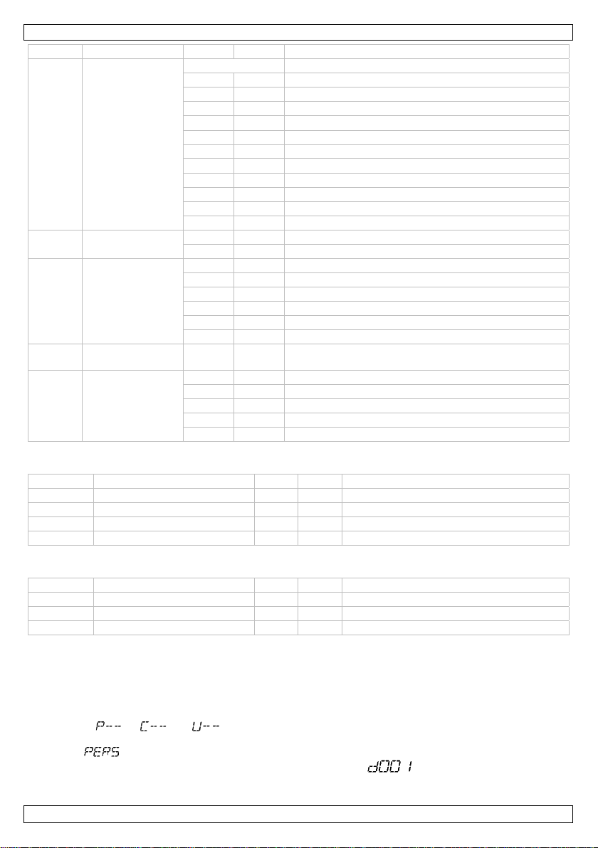
LX101
canal función de a descripción
blanco
201 205 3200K
206 210 3400K
211 215 4200K
216 220 4900K
221 225 5600K
226 230 5900K
231 235 6500K
236 240 7200K
241 245 8000K
246 250 8500K
251 255 10 000K
6 estroboscopio
000 009 estroboscopio desactivado
010 255 estroboscopio 0 ~20Hz (lento ~ rápido)
000 051 sin función
052 101 programa automático 1
7
programas
automáticos
102 152 programa automático 2
153 203 programa automático 3
204 254 programa automático 4
255 - programa automático 5
8 velocidad 000 255
velocidad de los programas automáticos (lento ~
rápido)
000 051 velocidad del dimmer por defecto
052 101 dimmer lineal
9 dimmer
102 152 dimmer no lineal 1
153 203 dimmer no lineal 2
204 255 dimmer no lineal 3
Modo de 4 canales
canal función de a descripción
1 dimmer maestro 000 255 0 ~ 100%
2 rojo 000 255 0 ~ 100%
3 verde 000 255 0 ~ 100%
4 azul 000 255 0 ~ 100%
Modo de 3 canales
canal función de a descripción
1 rojo 000 255 0 ~ 100%
2 verde 000 255 0 ~ 100%
3 azul 000 255 0 ~ 100%
7.5 Modo maestro/esclavo
Este modo permite controlar varios focos simultáneamente.
1. Utilice cables DMX estándar e interconecte sus focos. Equipe el último foco de la serie con una
resistencia de terminación.
2. Ajuste el primer foco de la serie como aparato maestro. Pulse la tecla <MENU> y seleccione un
modo ( , o ).
3. Seleccione el mismo modo de canal para cada aparato esclavo que el modo del aparato maestro
(por ).
4. Ponga la dirección DMX de todos los aparatos esclavos en 1 ( ).
V. 01 – 06/06/2012 29 ©Velleman nv
Page 30
LX101
8. Limpieza y mantenimiento
• Apriete bien las tuercas y los tornillos y verifique que no hay señales de oxidación.
• No modifique la caja, los soportes y las conexiones p.ej. no taladre agujeros adicionales en un
soporte o no modifique las conexiones, etc.
• Las partes móviles no pueden mostrar ningún rastro de desgaste y deben estar bien equilibradas.
• No dañe los cables de alimentación. Contacte con un técnico especializado para instalar el aparato.
• Quite el polvo regularmente de la caja y los orificios de ventilación con un paño húmedo.
• El usuario no habrá de efectuar el mantenimiento de ninguna pieza. Contacte con su distribuidor si
necesita piezas de recambio.
Reemplazar el fusible
1. Desatornille el portafusibles [6] con el destornillador con punta plana.
2. Saque el fusible fundido y reemplácelo.
3. Vuelva a poner el portafusibles en su lugar.
9. Especificaciones
alimentación 240VAC ~ 50Hz
consumo 45W
fuente de luz 18x LED tricolor high-power de 3 W
ángulo del haz 20°
flujo luminoso 9600 lm @ 1 m
dimensiones 255 x 255 x 80mm
peso 3.5kg
Utilice este aparato sólo con los accesorios originales. Velleman NV no será responsable de
daños ni lesiones causados por un uso (indebido) de este aparato.
Para más información sobre este producto y la versión más reciente de este manual del
usuario, visite nuestra página www. luxibel.com.
Se pueden modificar las especificaciones y el contenido de este manual sin previo aviso.
© DERECHOS DE AUTOR
Velleman NV dispone de los derechos de autor para este manual del usuario. Todos los
derechos mundiales reservados.
Está estrictamente prohibido reproducir, traducir, copiar, editar y guardar este manual del usuario o
partes de ello sin previo permiso escrito del derecho habiente.
V. 01 – 06/06/2012 30 ©Velleman nv
Page 31
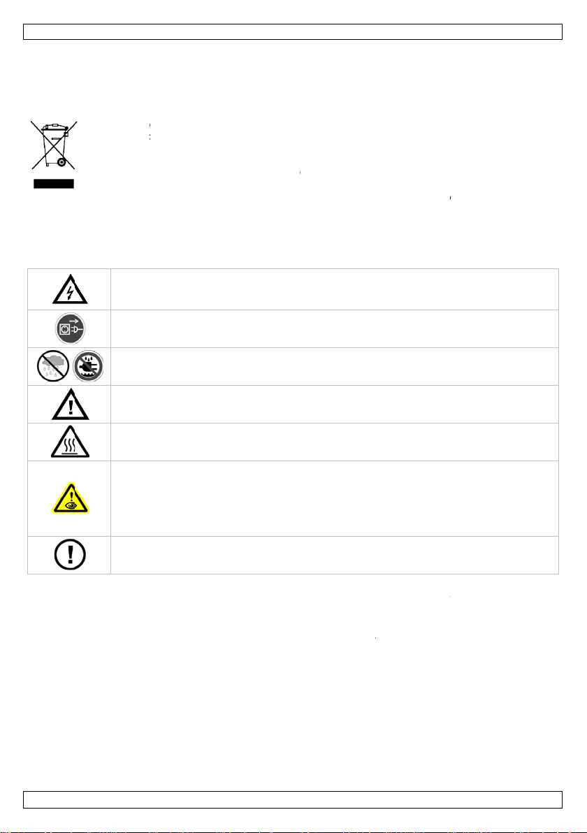
0
E
E
e
w
g
S
A
d
e
h
e
h
o
u
g
r
r
o
c
v
B
e
e
n
e
n
S
u
z
n
e
n
u
n
t
r
m
ä
e
c
e
d
e
ä
n
ä
m
d
E
n
e
u
n
a
e
a
e
1
a
n
r
L
k
e
i
e
e
n
h
z
n
t
s
e
m
f
n
0
u
m
a
e
o
l
o
.
t
f
n
m
h
c
)
A
t
s
o
r
c
w
e
U
z
m
o
e
o
n
t
v
ä
e
i
h
t
n
a
r
r
t
h
E
E
y
n
ö
r
s
v
i
v
n
e
e
m
t
s
t
ä
m
s
i
d
m
n
u
n
e
s
t
n
.
l
LX1
1
1.
An alle
Wichtig
Falls Z
Wir beda
sorgfälti
das Gerä
2.
•
Der
geer
•
Verg
besc
•
Acht
werd
•
Mac
•
Sorg
expl
•
Beac
bele
•
Beac
völli
inführung
inwohner de
Umweltinfo
Dieses Symb
Produktes na
Einheit (oder
verwendeten
werden. Dies
retourniert w
eifel bestehe
nken uns für d
durch. Überpr
t nicht und we
icherheits
Seien
Spann
führen.
Trenne
Sie da
Verwe
Feucht
Halten
Achtu
heizt a
Blicke
•
•
•
zu ver
Es gibt
Fachhä
ufbau des Ger
et sein. Der el
wissern Sie si
rieben in dies
n Sie darauf,
en kann. Bei B
en Sie das Ger
en Sie für eine
siven Gegenst
hten Sie eine
chteten Fläche
hten Sie, dass
.
BEDI
Europäische
mationen üb
l auf dem Prod
h seinem Lebe
erwendeten B
atterien müss
Einheit muss
rden. Respekti
, wenden Sie
n Kauf des LX
üfen Sie, ob Tr
den Sie sich a
hinweise
ie während de
ng stehenden
n Sie das Gerät
u den Netzstec
den Sie das G
.
Sie Kinder und
g: Berühren S
f.
Sie nicht dir
epi
leptische Anfäll
zei
liche Blindheid
pe
manente und u
eiden.
keine zu warte
ndler.
tes entspricht
ktrische Ansc
h, dass die an
r Bedienungsa
ass die Netzlei
schädigungen
t mit einem g
Abstand von
nden oder Sto
inimale Entfer
.
ie Lüftungssch
NUNGS
Union
r dieses Prod
kt oder der Ve
szyklus der U
tterien) nicht
n von einer sp
n den Händler
ren Sie die ört
sich für Ents
01! Lesen Sie
nsportschäden
Ihren Händler
Installation de
eitungen könn
bei Nichtbenut
er an der Griff
rät nur im In
Unbefugte vo
e das Gehäuse
kt in die Lic
bei empfindli
(Blitzblindheid
nwiderrufliche
den Teile. Bes
der Schutzklas
luss darf nur v
uschließende N
leitung.
ung nicht gequ
oll eine Fachk
eigneten Siche
in. 0,5 m zwis
fen.
ung von 1 m z
litze nie blocki
ANLEIT
kt
rpackung zeigt
welt Schaden
ls unsortiertes
zialisierten Fir
der ein örtlich
ichen Umweltv
rgungsrichtli
diese Bedienun
vorliegen. Soll
s Gerätes sehr
e zu lebensgef
zung und vor j
läche an und z
enbereich. Sc
Gerät fern.
während des B
tquelle, um
hen Menschen
ugenschäden
ellen Sie even
e I. Gemäß de
n einer Fachkr
etzspannung ni
etscht oder du
aft das Kabel e
rheitskabel fest
hen dem Gerä
ischen der Lic
rt sind. Bedeck
NG
an, dass die En
ufügen kann.
Hausmüll; die
a zwecks Rec
s Recycling-U
rschriften.
ien an Ihre
gsanleitung vo
e dies der Fall
orsichtig: das
hrlichen elektr
der Reinigung
ehen Sie nie a
ützen Sie das
etriebs nicht, d
uelle Ersatzteil
Vorschriften
ft durchgeführ
cht höher ist al
ch scharfe Kan
setzen.
(z.B. VDLSC7
und entflamm
tausbeute und
en Sie das Ger
tsorgung diese
ntsorgen Sie d
inheit oder
cling entsorgt
ternehmen
rtliche Behör
Inbetriebnah
ein, verwende
Berühren von
schen Schläge
om Netz. Fass
der Netzleitun
Gerät vor Rege
nn das Gehäu
bei Ihrem
uss das Gerät
werden.
die Netzspan
en beschädigt
oder VDLSC8)
baren und
irgendeiner
t weder partiel
e
e.
e
Sie
nter
n
g.
n und
e
ung
noch
V. 01 –
6/06/2012
31
©Velle
an nv
Page 32

LX101
3. Allgemeine Richtlinien
Siehe Velleman® Service- und Qualitätsgarantie am Ende dieser Bedienungsanleitung.
Schützen Sie das Gerät vor Staub. Schützen Sie das Gerät vor extremen Temperaturen.
Beachten Sie, dass die Lüftungsschlitze nicht blockiert werden. Beachten Sie eine
minimale Entfernung von 2.5cm zwischen dem Gerät und jedem anderen Gegenstand.
Vermeiden Sie Erschütterungen. Vermeiden Sie rohe Gewalt während der Installation und
Bedienung des Gerätes.
• Nehmen Sie das Gerät erst in Betrieb, nachdem Sie sich mit seinen Funktionen vertraut gemacht
haben. Lassen Sie das Gerät nicht von Personen bedienen, die sich nicht mit dem Gerät auskennen.
Meist ist die Beschädigung des Gerätes das Ergebnis von unfachmännischer Bedienung.
• Eigenmächtige Veränderungen sind aus Sicherheitsgründen verboten. Bei Schäden verursacht durch
eigenmächtige Änderungen erlischt der Garantieanspruch.
• Mechanischer Schaden werden nicht durch die Garantie gedeckt.
• Verwenden Sie das Gerät nur für Anwendungen beschrieben in dieser Bedienungsanleitung sonst
kann dies zu Schäden am Produkt führen und erlischt der Garantieanspruch. Jede andere
Verwendung ist mit Gefahren wie Kurzschluss, Brandwunden, elektrischem Schlag, usw. verbunden.
• Bei Schäden, die durch Nichtbeachtung der Bedienungsanleitung verursacht werden, erlischt der
Garantieanspruch. Für daraus resultierende Folgeschäden übernimmt der Hersteller keine Haftung.
• Lassen Sie dieses Gerät von einem Fachmann installieren und warten.
• Das Gerät bei Temperaturschwankungen nicht sofort einschalten. Schützen Sie das Gerät vor
Beschädigung, indem Sie es ausgeschaltet lassen bis es akklimatisiert ist (Zimmertemperatur
erreicht hat).
• Dieses Gerät wurde für den professionellen Einsatz auf Bühnen, in Discotheken, Theatern, usw.
entworfen und eignet sich nur für die Anwendung im Innenbereich (<35°C, <75%RH). Verwenden
Sie das Gerät mit einer Wechselspannung von max. 240VAC / 50Hz.
• Das Gerät eignet sich nicht für permanenten Betrieb: eine regelmäßige Pause verlängert die
Lebensdauer.
• Verwenden Sie die Originalverpackung, wenn das Gerät transportiert werden soll.
• Bewahren Sie diese Bedienungsanleitung für künftige Einsichtnahme auf.
4. Eigenschaften
• PAR-Scheinwerfer mit dreifarbigen LEDs
• sehr schmal
• 3 fließende Dimm-Modi für eine perfekte Farbmischung
• DMX-Steuerung über max. 9 Kanäle
o 3 channels: RGB
o 4 channels: RGB, dimmer
o 9 channels: RGB, dimmer, colour temperature, shutter, auto, dimming curves
• eingebaute Programme
• doppelte Halterung: kann als Bodenscheinwerfer verwendet werden
• mit Filterrahmen, kann mit Torblende verwendet werden (optional): VDLBD56B
5. Umschreibung
Siehe Abbildungen, Seite 2 dieser Bedienungsanleitung.
1 LCD-Display 5 Netzausgang (PowerCon)
2 DMX-Ausgang 6 Sicherungshalter
3 DMX-Eingang 7 Befestigung Sicherheitsseil
4 Netzeingang (PowerCon) 8 GND-Anschluss
V. 01 – 06/06/2012 32 ©Velleman nv
Page 33

LX101
6. Installation
Siehe Abbildungen, Seite 2 dieser Bedienungsanleitung.
6.1 Das Gerät montieren
•
Lassen Sie das Gerät von einem Fachmann und gemäß den EN 60598-2-17 und allen anderen
zutreffenden Normen installieren.
• Die Konstruktion muss während einer Stunde eine Punktlast von maximal 10 x dem Gewicht des
Geräts tragen können, ohne dass Verformung verursacht wird.
• Das Gerät muss immer mit einer zweiten Befestigung z.B. mit einem Sicherheitskabel gesichert
werden [7].
• Stehen Sie während der Montage, Entfernung oder Wartung nie direkt unter dem Gerät. Lassen Sie
das Gerät jährlich und vor der Inbetriebnahme von einem Fachmann prüfen.
• Montieren Sie das Gerät an einem Ort, an dem es wenig Vorübergehende gibt und der unzugänglich
ist für Unbefugte.
• Oberirdische Montage erfordert erhebliche Sachkenntnis in Bezug auf das Berechnen der maximalen
Lasten, das geeignete Montagematerial…Lassen Sie das Material und das Gerät regelmäßig
kontrollieren. Versuchen Sie das Gerät nicht selber zu installieren, denn wenn Sie nicht über diese
Qualifikationen verfügen, könnte es zu Verletzungen führen.
• Regeln Sie den Neigungswinkel über den Montagebügel und drehen Sie die Schrauben fest an.
• Lassen Sie das Gerät von einem qualifizierten Elektriker anschließen.
• Schließen Sie das Gerät an das Hauptnetz und nicht an einen Dimmer an.
6.2 DMX512-Anschluss
Wenn nötig, so verbinden Sie ein XLR-Kabel mit dem 3-Pin XLR-Ausgang der Steuerung (nicht
•
mitgeliefert) und die andere Seite mit dem 3-Pin XLR-Eingang des LX101. Sie können verschiedene
LX101 in Serie schalten. Verwenden Sie ein zweipoliges abgeschirmtes Kabel mit XLR Ein- und
Ausgangsanschlüssen.
• Die max. empfohlene Kabellänge ist 500 Meter, die Höchstzahl von Geräten, verbunden mit
demselben Anschluss ist 32.
• Ein DMX-Abschlusswiderstand ist empfehlenswert für Installationen, bei denen das DMX-Kabel lang
ist oder in einer Umgebung mit vielem elektrischem Rauschen (z.B. Discos). Der Abschlusswiderstand
verhindert Störung des digitalen Steuersignals durch elektrisches Rauschen. Der DMXAbschlusswiderstand ist nur eine XLR-Buchse mit einem 120Ω Widerstand zwischen 2 und 3, die den
XLR-Ausgang des letzten Geräts in der Kette angeschlossen wird.
6.3 General
•
Achten Sie darauf, dass sich kein entflammbares Material in einem Umkreis von 50 cm befindet und
beachten Sie, dass es genügend Kühlung gibt.
• Lassen Sie das Gerät von einem qualifizierten Elektriker anschließen.
• Stecken Sie zuerst den PowerCon-Stecker in den Eingang [4] und verbinden Sie das Gerät mit dem
Netz.
• Beachten Sie, dass alle Geräte über eine geerdete Steckdose und nicht über einen Regelwiderstand
oder Dimmkreis versorgt werden, auch wenn Sie den Regelwiderstand oder den Dimmkreis als
EIN/AUS-Schalter (0% bis 100%) verwenden.
• Die Installation muss vor Inbetriebnahme von einem Experten genehmigt werden.
7. Anwendung
Siehe Abbildungen, Seite 2 dieser Bedienungsanleitung.
7.1 Bedienfeld
Bedienen Sie das Bedienfeld mit den vier Tasten unten im LCD-Display.
Taste Funktion
<MENU> Zugang zum Menü oder zum vorigen Menü zurückkehren
<ENTER>< Eine Option auswählen und bestätigen
<UP> Durch die verschiedenen Menü-Optionen in aufsteigender Reihenfolge blättern
DOWN> Durch die verschiedenen Menü-Optionen in absteigender Reihenfolge blättern
V. 01 – 06/06/2012 33 ©Velleman nv
Page 34

LX101
Die ausgewählte Menüfunktion wird im LCD-Display angezeigt. Das LCD-Display zeigt auch die nächste
Menü-Option unter die Funktion an. Wählen Sie eine Menü-Option mit <ENTER> aus.
Blättern Sie mit <UP> und <DOWN> durch das Menü. Wählen Sie die Menüfunktion mit <ENTER> aus
und drücken Sie auf <MENÜ> um ohne Änderung vom Wert zum Hauptmenü zurückzukehren.
7.2 Menüfunktionen
Menü Submenü Funktion Beschreibung
interne Programme
Geschwindigkeit
Adresse
Kanal-Modus
Dimm-Geschwindigkeit
Rot
Grün
Blau
Cyan
Magenta
Gelb
Weiß
Rot Farbton Rot ( ~ )
Grün
Blau
Stroboskopgeschwindigkeit Stroboskopeffekt hinzufügen ( ~ )
interne Programme mit plötzliche oder allmähliche
Übergang
Geschwindigkeit der internen Programme (
~ )
DMX-Adresse ( ~ )
3-Kanal DMX-Steuerung
4-Kanal DMX-Steuerung
9-Kanal DMX-Steuerung
keine Dimm-Geschwindigkeit
schnelle Geschwindigkeit
durchschnittliche Geschwindigkeit
langsame Geschwindigkeit
Wählen Sie zwischen 7 statischen Farben
Farbton Grün ( ~ )
Farbton Blau ( ~ )
7.3 Autonomer Modus (Stand-Alone)
Automatische Steuerung
1. Drücken Sie auf <MENÜ> bis im LCD-Display erscheint.
2. Bestätigen Sie Ihre Wahl mit <ENTER>.
3. Wählen Sie das gewünschte Programm ( ~ ) mit <UP> und <DOWN>.
4. Bestätigen Sie Ihre Wahl mit <ENTER>.
5. Stellen Sie die Geschwindigkeit der internen Programme mit <UP> oder <DOWN> ( ~
6. Drücken Sie auf <MODE> um zu bestätigen.
Interne Farben
Dieser Scheinwerfer hat verschiedene statische vorprogrammierte Farben.
1. Drücken Sie auf <MENÜ> bis im LCD-Display erscheint.
2. Bestätigen Sie Ihre Wahl mit <ENTER>.
3. Wählen Sie das gewünschte Programm ( ~ ) mit <UP> und <DOWN>.
4. Bestätigen Sie Ihre Wahl mit <ENTER>.
Eine statische Farbe kreieren
Mit diesem Scheinwerfer können Sie selber Farben kreieren.
1. Drücken Sie auf <MENÜ> bis im LCD-Display erscheint.
2. Bestätigen Sie Ihre Wahl mit <ENTER>.
3. Wählen Sie die gewünschte Farbe mit <UP> oder <DOWN> aus.
V. 01 – 06/06/2012 34 ©Velleman nv
) ein.
Page 35

LX101
4. Ändern Sie den Farbwert mit <ENTER> ( ~ , von 0 bis 100%).
5. Bestätigen Sie Ihre Wahl und gehen Sie mit <ENTER> zur nächsten Farbe (Grün, Blau). Geben Sie
nun auch den Wert für die zwei nächsten Farben ein.
6. Drücken Sie auf <ENTER> und stellen Sie den Stroboskopeffekt mit <UP> oder <DOWN> (
(aus) ~ (max.)).
7. Bestätigen Sie nun mit <ENTER>. Die erste Farbe wird ausgewählt. Drücken Sie auf <MENÜ> um
das Menü zu verlassen.
Die Dimmer-Geschwindigkeit einstellen
1. Drücken Sie auf <MENU> bis im Display erscheint.
2. Bestätigen Sie Ihre Wahl mit <ENTER>.
3. Wählen Sie die gewünschte Dimmgeschwindigkeit mit <UP> oder <DOWN> ( , ~
).
4. Bestätigen Sie Ihre Wahl mit <ENTER>.
7.4 DMX-Steuerung
Steuerung vom Gerät über einen universellen DMX-Controller.
• Alle DMX-gesteuerten Geräte brauchen eine digitale Startadresse, sodass das richtige Gerät auf die
Signale reagieren kann. Diese digitale Startadresse ist die Kanalnummer, von der das Gerät die
Befehle der DMX-Steuerung empfängt und ausführt. Sie können dieselbe Startadresse für eine ganze
Gruppe von Geräten verwenden oder eine separate Startadresse für jedes Gerät eingeben.
• Wenn alle Geräte dieselbe Startadresse haben, werden sie auf einem spezifischen Kanal das
Steuersignal empfangen. Mit anderen Worten, wenn Sie die Einstellungen von einem Kanal ändern,
werden alle Geräte zur gleichen Zeit beeinflusst. Wenn Sie verschiedene Adressen einstellen, wird
jedes Gerät auf einem anderen Kanal Signale empfangen. Wenn Sie die Einstellungen ändern, wird
nur das besagte Gerät beeinflusst.
o Im Falle des 3-Kanal LX101, werden Sie die Startadresse des ersten Gerätes auf 1 (CH1~3),
der zweiten Einheit auf 4 (1 + 3) (CH4~6), der dritten Einheit auf 7 (4 + 3) (CH7~9) usw.
einstellen müssen.
o Im Falle des 4-Kanal LX101, werden Sie die Startadresse des ersten Gerätes auf 1 (CH1~4),
der zweiten Einheit auf 5 (1 + 4) (CH5~8), der dritten Einheit auf 9 (5 + 4) (CH9~12) usw.
einstellen müssen.
o Im Falle des 9-Kanal LX101, werden Sie die Startadresse des ersten Gerätes auf 1 (CH1~9),
der zweiten Einheit auf 10 (1 + 9) (CH10~18), der dritten Einheit auf 19 (10 + 9) (CH19~27)
1. Drücken Sie auf <MENÜ> bis im LCD-Display erscheint.
2. Bestätigen Sie Ihre Wahl mit <ENTER>.
3. Wählen Sie die Anzahl DMX-Kanäle mit <UP> oder <DOWN> ( , oder )
4. Drücken Sie auf MENU> bis im LCD-Display erscheint.
5. Bestätigen Sie Ihre Wahl mit <ENTER>.
6. Wählen Sie die DMX-Startadresse mit <UP> oder <DOWN> ( ~ ).
DMX-Werte pro Kanal
9-Kanal-Modus
usw. einstellen müssen.
Kanal Funktion Von bis Umschreibung
1 Master-Dimmer 000 255 0 ~ 100%
Rot
2
Grün
3
000 255
000 255
0 ~ 100%
(oder Schrittdauer für automatisches Programm)
0 ~ 100%
(oder Fade-Dauer für automatisches Programm)
4 Blau 000 255 0 ~ 100%
000 010 keine Funktion
Rot Grün Blau
5 Farbmakros
011 255 100%
031 050
T
S
100% 0%
051 070 0% 100%
071 090 0%
T
0%
S
100%
V. 01 – 06/06/2012 35 ©Velleman nv
Page 36

LX101
r
Kanal Funktion Von bis Umschreibung
091 110
111 130 100% 0%
131 150 100%
151 170
S
0% 100%
S S
T T
T
100%
171 200 100% 100% 100%
Weiß
201 205 3200K
206 210 3400K
211 215 4200K
216 220 4900K
221 225 5600K
226 230 5900K
231 235 6500K
236 240 7200K
241 245 8000K
246 250 8500K
251 255 10 000K
6 Stroboskop
000 009 Stroboskop ausgeschaltet
010 255 Stroboskop 0 ~20Hz (langsam ~ schnell)
000 051 keine Funktion
052 101 automatisches Programm 1
7
automatische
Programme
102 152 automatisches Programm 2
153 203 automatisches Programm 3
204 254 automatisches Programm 4
255 - automatisches Programm 5
8 Geschwindigkeit 000 255
000 051 Standard Dimme
Geschwindigkeit der automatischen Programme
(langsam ~ schnell)
-Geschwindigkeit
052 101 linearer Dimmer
9 Dimmer
102 152 non-linearer Dimmer 1
153 203 non-linearer Dimmer 2
204 255 non-linearer Dimmer 3
4-Kanal-Modus
Kanal Funktion Von bis Umschreibung
1 Master-Dimmer 000 255 0 ~ 100%
2 Rot 000 255 0 ~ 100%
3 Grün 000 255 0 ~ 100%
4 Blau 000 255 0 ~ 100%
3-Kanal-Modus
Kanal Funktion Von bis Umschreibung
1 Rot 000 255 0 ~ 100%
2 Grün 000 255 0 ~ 100%
3 Blau 000 255 0 ~ 100%
V. 01 – 06/06/2012 36 ©Velleman nv
Page 37

LX101
7.5 Master/Slave-Steuerung
Gleichzeitige Steuerung mehrerer Geräte.
1. Verbinden Sie Ihre Geräte über Standard DMX-Kabel miteinander. Verwenden Sie bei längeren
Kabellängen einen Abschlusswiderstand für das letzte Gerät.
2. Wählen Sie das erste Gerät in der Reihe als Master-Gerät. Drücken Sie auf <MENÜ> und wählen Sie
einen Ansteuermodus ( , or ).
3. Wählen Sie denselben Kanalmodus für jedes Slave-Gerät aus als diesen des Master-Gerätes (über
4. Stellen Sie die DMX-Adresse aller Slave-Geräte auf 1 ( ).
).
8. Reinigung und Wartung
• Verwendete Schrauben müssen fest angespannt werden und dürfen keine Rostspuren zeigen.
• Das Gehäuse, die Linsen, die Montagebügel und der Montageort (z.B. Decke oder Gebinde) dürfen
nicht angepasst werden, z.B. bohren Sie keine zusätzlichen Löcher in Montagebügeln, verändern Sie
die Anschlüsse nicht, usw.
• Mechanisch bewegende Teile dürfen keine Spuren von Abnutzung aufweisen.
• Sorgen Sie dafür, dass die Netzkabel nicht beschädigt sind. Lassen Sie das Gerät von einer Fachkraft
installieren.
• Entfernen Sie den Staub regelmäßig mit einem feuchten Tuch vom Gehäuse und den
Lüftungsschlitzen.
• Die Teile dürfen nicht eigenmächtig ersetzt werden. Bestellen Sie eventuelle Ersatzteile bei Ihrem
Fachhändler.
Die Sicherung ersetzen
1. Lockern Sie den Sicherungshalter [6] mit einem Schlitz-Schraubendreher.
2. Entfernen Sie die defekte Sicherung und setzen Sie eine neue Sicherung gleichen Typs ein.
3. Bringen Sie den Sicherungshalter wieder in das Gehäuse ein und verbinden Sie das Gerät mit dem
Netz.
9. Technische Daten
Stromversorgung 240VAC ~ 50Hz
Stromverbrauch 45W
Lichtquelle 18x dreifarbige, high-power LEDs von 3W
Abstrahlwinkel 20°
Lichtstrom 9600 lm @ 1 m
Abmessungen 255 x 255 x 80mm
Gewicht 3.5kg
Verwenden Sie dieses Gerät nur mit originellen Zubehörteilen. Velleman NV übernimmt keine
Haftung für Schaden oder Verletzungen bei (falscher) Anwendung dieses Gerätes. Für mehr
Informationen zu diesem Produkt und die neueste Version dieser Bedienungsanleitung, siehe
www. luxibel.com. Alle Änderungen ohne vorherige Ankündigung vorbehalten.
© URHEBERRECHT
Velleman NV besitzt das Urheberrecht für diese Bedienungsanleitung. Alle weltweiten Rechte
vorbehalten.
Ohne vorherige schriftliche Genehmigung des Urhebers ist es nicht gestattet, diese Bedienungsanleitung
ganz oder in Teilen zu reproduzieren, zu kopieren, zu übersetzen, zu bearbeiten oder zu speichern.
V. 01 – 06/06/2012 37 ©Velleman nv
Page 38

Velleman® Service and Quality Warranty
Since its foundation in 1972, Velleman® acquired extensive experience in
the electronics world and currently distributes its products in over 85
countries.
All our products fulfil strict quality requirements and legal stipulations in
the EU. In order to ensure the quality, our products regularly go through
an extra quality check, both by an internal quality department and by
specialized external organisations. If, all precautionary measures
notwithstanding, problems should occur, please make appeal to our
warranty (see guarantee conditions).
General Warranty Conditions Concerning Consumer Products (for
EU):
• All consumer products are subject to a 24-month warranty on production
flaws and defective material as from the original date of purchase.
• Velleman® can decide to replace an article with an equivalent article, or
to refund the retail value totally or partially when the complaint is valid and
a free repair or replacement of the article is impossible, or if the expenses
are out of proportion.
You will be delivered a replacing article or a refund at the value of 100%
of the purchase price in case of a flaw occurred in the first year after the
date of purchase and delivery, or a replacing article at 50% of the
purchase price or a refund at the value of 50% of the retail value in case
of a flaw occurred in the second year after the date of purchase and
delivery.
• Not covered by warranty:
- all direct or indirect damage caused after delivery to the article (e.g. by
oxidation, shocks, falls, dust, dirt, humidity...), and by the article, as well
as its contents (e.g. data loss), compensation for loss of profits;
- consumable goods, parts or accessories that are subject to an aging
process during normal use, such as batteries (rechargeable, nonrechargeable, built-in or replaceable), lamps, rubber parts, drive belts...
(unlimited list);
- flaws resulting from fire, water damage, lightning, accident, natural
disaster, etc.…;
- flaws caused deliberately, negligently or resulting from improper
handling, negligent maintenance, abusive use or use contrary to the
manufacturer’s instructions;
- damage caused by a commercial, professional or collective use of the
article (the warranty validity will be reduced to six (6) months when the
article is used professionally);
- damage resulting from an inappropriate packing and shipping of the
article;
- all damage caused by modification, repair or alteration performed by a
third party without written permission by Velleman®.
• Articles to be repaired must be delivered to your Velleman® dealer,
solidly packed (preferably in the original packaging), and be completed
with the original receipt of purchase and a clear flaw description.
• Hint: In order to save on cost and time, please reread the manual and
check if the flaw is caused by obvious causes prior to presenting the
article for repair. Note that returning a non-defective article can also
involve handling costs.
• Repairs occurring after warranty expiration are subject to shipping costs.
• The above conditions are without prejudice to all commercial warranties.
The above enumeration is subject to modification according to the
article (see article’s manual).
Velleman® service- en kwaliteitsgarantie
Velleman® heeft sinds zijn oprichting in 1972 een ruime ervaring
opgebouwd in de elektronicawereld en verdeelt op dit moment producten
in meer dan 85 landen. Al onze producten beantwoorden aan strikte
kwaliteitseisen en aan de wettelijke bepalingen geldig in de EU. Om de
kwaliteit te waarborgen, ondergaan onze producten op regelmatige
tijdstippen een extra kwaliteitscontrole, zowel door onze eigen
kwaliteitsafdeling als door externe gespecialiseerde organisaties. Mocht
er ondanks deze voorzorgen toch een probleem optreden, dan kunt u
steeds een beroep doen op onze waarborg (zie waarborgvoorwaarden).
Algemene waarborgvoorwaarden consumentengoederen (voor
Europese Unie):
• Op alle consumentengoederen geldt een garantieperiode van 24
maanden op productie- en materiaalfouten en dit vanaf de oorspronkelijke
aankoopdatum.
• Indien de klacht gegrond is en een gratis reparatie of vervanging van
een artikel onmogelijk is of indien de kosten hiervoor buiten verhouding
zijn, kan Velleman® beslissen het desbetreffende artikel te vervangen
door een gelijkwaardig artikel of de aankoopsom van het artikel
gedeeltelijk of volledig terug te betalen. In dat geval krijgt u een
vervangend product of terugbetaling ter waarde van 100% van de
aankoopsom bij ontdekking van een gebrek tot één jaar na aankoop en
levering, of een vervangend product tegen 50% van de kostprijs of
terugbetaling van 50 % bij ontdekking na één jaar tot 2 jaar.
• Valt niet onder waarborg:
- alle rechtstreekse of onrechtstreekse schade na de levering veroorzaakt
aan het toestel (bv. door oxidatie, schokken, val, stof, vuil, vocht...), en
door het toestel, alsook zijn inhoud (bv. verlies van data), vergoeding voor
eventuele winstderving.
- verbruiksgoederen, onderdelen of hulpstukken die onderhevig zijn aan
veroudering door normaal gebruik zoals bv. batterijen (zowel oplaadbare
als niet-oplaadbare, ingebouwd of vervangbaar), lampen, rubberen
onderdelen, aandrijfriemen... (onbeperkte lijst).
- defecten ten gevolge van brand, waterschade, bliksem, ongevallen,
natuurrampen, enz.
- defecten veroorzaakt door opzet, nalatigheid of door een
onoordeelkundige behandeling, slecht onderhoud of abnormaal gebruik of
gebruik van het toestel strijdig met de voorschriften van de fabrikant.
- schade ten gevolge van een commercieel, professioneel of collectief
gebruik van het apparaat (bij professioneel gebruik wordt de
garantieperiode herleid tot 6 maand).
- schade veroorzaakt door onvoldoende bescherming bij transport van het
apparaat.
- alle schade door wijzigingen, reparaties of modificaties uitgevoerd door
derden zonder toestemming van Velleman®.
• Toestellen dienen ter reparatie aangeboden te worden bij uw
Velleman®-verdeler. Het toestel dient vergezeld te zijn van het
oorspronkelijke aankoopbewijs. Zorg voor een degelijke verpakking (bij
voorkeur de originele verpakking) en voeg een duidelijke foutomschrijving
bij.
• Tip: alvorens het toestel voor reparatie aan te bieden, kijk nog eens na
of er geen voor de hand liggende reden is waarom het toestel niet naar
behoren werkt (zie handleiding). Op deze wijze kunt u kosten en tijd
besparen. Denk eraan dat er ook voor niet-defecte toestellen een kost
voor controle aangerekend kan worden.
• Bij reparaties buiten de waarborgperiode zullen transportkosten
aangerekend worden.
• Elke commerciële garantie laat deze rechten onverminderd.
Bovenstaande opsomming kan eventueel aangepast worden
naargelang de aard van het product (zie handleiding van het
betreffende product).
Garantie de service et de qualité Velleman®
Depuis 1972, Velleman® a gagné une vaste expérience dans le secteur
de l’électronique et est actuellement distributeur dans plus de 85 pays.
Tous nos produits répondent à des exigences de qualité rigoureuses et à
des dispositions légales en vigueur dans l’UE. Afin de garantir la qualité,
nous soumettons régulièrement nos produits à des contrôles de qualité
supplémentaires, tant par notre propre service qualité que par un service
qualité externe. Dans le cas improbable d’un défaut malgré toutes les
précautions, il est possible d’invoquer notre garantie (voir les conditions
de garantie).
Conditions générales concernant la garantie sur les produits grand
public (pour l’UE) :
• tout produit grand public est garanti 24 mois contre tout vice de
production ou de matériaux à dater du jour d’acquisition effective ;
• si la plainte est justifiée et que la réparation ou le remplacement d’un
article est jugé impossible, ou lorsque les coûts s’avèrent
disproportionnés, Velleman® s’autorise à remplacer ledit article par un
article équivalent ou à rembourser la totalité ou une partie du prix d’achat.
Le cas échéant, il vous sera consenti un article de remplacement ou le
remboursement complet du prix d’achat lors d’un défaut dans un délai de
1 an après l’achat et la livraison, ou un article de remplacement
moyennant 50% du prix d’achat ou le remboursement de 50% du prix
d’achat lors d’un défaut après 1 à 2 ans.
• sont par conséquent exclus :
- tout dommage direct ou indirect survenu à l’article après livraison (p.ex.
dommage lié à l’oxydation, choc, chute, poussière, sable, impureté…) et
provoqué par l’appareil, ainsi que son contenu (p.ex. perte de données) et
une indemnisation éventuelle pour perte de revenus ;
- toute pièce ou accessoire nécessitant un remplacement causé par un
usage normal comme p.ex. piles (rechargeables comme non
rechargeables, intégrées ou remplaçables), ampoules, pièces en
caoutchouc, courroies… (liste illimitée) ;
- tout dommage qui résulte d’un incendie, de la foudre, d’un accident,
d’une catastrophe naturelle, etc. ;
Page 39

- out dommage provoqué par une négligence, volontaire ou non, une
utilisation ou un entretien incorrect, ou une utilisation de l’appareil
contraire aux prescriptions du fabricant ;
- tout dommage à cause d’une utilisation commerciale, professionnelle ou
collective de l’appareil (la période de garantie sera réduite à 6 mois lors
d’une utilisation professionnelle) ;
- tout dommage à l’appareil qui résulte d’une utilisation incorrecte ou
différente que celle pour laquelle il a été initialement prévu comme décrit
dans la notice ;
- tout dommage engendré par un retour de l’appareil emballé dans un
conditionnement non ou insuffisamment protégé.
- toute réparation ou modification effectuée par une tierce personne sans
l’autorisation explicite de SA Velleman® ; - frais de transport de et vers
Velleman® si l’appareil n’est plus couvert sous la garantie.
• toute réparation sera fournie par l’endroit de l’achat. L’appareil doit
nécessairement être accompagné du bon d’achat d’origine et être dûment
conditionné (de préférence dans l’emballage d’origine avec mention du
défaut) ;
• tuyau : il est conseillé de consulter la notice et de contrôler câbles, piles,
etc. avant de retourner l’appareil. Un appareil retourné jugé défectueux
qui s’avère en bon état de marche pourra faire l’objet d’une note de frais à
charge du consommateur ;
• une réparation effectuée en-dehors de la période de garantie fera l’objet
de frais de transport ;
• toute garantie commerciale ne porte pas atteinte aux conditions
susmentionnées.
La liste susmentionnée peut être sujette à une complémentation
selon le type de l’article et être mentionnée dans la notice d’emploi.
Garantía de servicio y calidad Velleman®
Desde su fundación en 1972 Velleman® ha adquirido una amplia
experiencia como distribuidor en el sector de la electrónica en más de 85
países. Todos nuestros productos responden a normas de calidad
rigurosas y disposiciones legales vigentes en la UE. Para garantizar la
calidad, sometemos nuestros productos regularmente a controles de
calidad adicionales, tanto a través de nuestro propio servicio de calidad
como de un servicio de calidad externo. En el caso improbable de que
surgieran problemas a pesar de todas las precauciones, es posible
recurrir a nuestra garantía (véase las condiciones de garantía).
Condiciones generales referentes a la garantía sobre productos de
venta al público (para la Unión Europea):
• Todos los productos de venta al público tienen un período de garantía
de 24 meses contra errores de producción o errores en materiales desde
la adquisición original;
• Si la queja está fundada y si la reparación o sustitución de un artículo no
es posible, o si los gastos son desproporcionados, Velleman® autoriza
reemplazar el artículo por un artículo equivalente o reembolsar la
totalidad o una parte del precio de compra. En este caso, usted recibirá
un artículo de recambio o el reembolso completo del precio de compra si
encuentra algún fallo hasta un año después de la compra y entrega, o un
artículo de recambio al 50% del precio de compra o el reembolso del 50%
del precio de compra si encuentra un fallo después de 1 año y hasta los 2
años después de la compra y entrega.
Por consiguiente, están excluidos entre otras cosas:
- todos los daños causados directa o indirectamente al aparato (p.ej. por
oxidación, choques, caída,...) y a su contenido (p.ej. pérdida de datos)
después de la entrega y causados por el aparato, y cualquier
indemnización por posible pérdida de ganancias;
- partes o accesorios, que estén expuestos al desgaste causado por un
uso normal, como por ejemplo baterías (tanto recargables como no
recargables, incorporadas o reemplazables), bombillas, partes de goma,
etc. (lista ilimitada);
- defectos causados por un incendio, daños causados por el agua, rayos,
accidentes, catástrofes naturales, etc.;
- defectos causados a conciencia, descuido o por malos tratos, un
mantenimiento inapropiado o un uso anormal del aparato contrario a las
instrucciones del fabricante;
- daños causados por un uso comercial, profesional o colectivo del
aparato (el período de garantía se reducirá a 6 meses con uso
profesional);
- daños causados por un uso incorrecto o un uso ajeno al que está
previsto el producto inicialmente como está descrito en el manual del
usuario;
- daños causados por una protección insuficiente al transportar el
aparato.
- daños causados por reparaciones o modificaciones efectuadas por una
tercera persona sin la autorización explícita de Velleman®;
- se calcula gastos de transporte de y a Velleman® si el aparato ya no
está cubierto por la garantía.
• Cualquier artículo que tenga que ser reparado tendrá que ser devuelto a
su distribuidor Velleman®. Devuelva el aparato con la factura de compra
original y transpórtelo en un embalaje sólido (preferentemente el
embalaje original). Incluya también una buena descripción del fallo;
• Consejo: Lea el manual del usuario y controle los cables, las pilas, etc.
antes de devolver el aparato. Si no se encuentra un defecto en el artículo
los gastos podrían correr a cargo del cliente;
• Los gastos de transporte correrán a carga del cliente para una
reparación efectuada fuera del período de garantía.
• Cualquier gesto comercial no disminuye estos derechos.
La lista previamente mencionada puede ser adaptada según el tipo
de artículo (véase el manual del usuario del artículo en cuestión).
Velleman® Service- und Qualitätsgarantie
Seit der Gründung in 1972 hat Velleman® sehr viel Erfahrung als Verteiler
in der Elektronikwelt in über 85 Ländern aufgebaut.
Alle Produkte entsprechen den strengen Qualitätsforderungen und
gesetzlichen Anforderungen in der EU. Um die Qualität zu gewährleisten
werden unsere Produkte regelmäßig einer zusätzlichen Qualitätskontrolle
unterworfen, sowohl von unserer eigenen Qualitätsabteilung als auch von
externen spezialisierten Organisationen. Sollten, trotz aller
Vorsichtsmaßnahmen, Probleme auftreten, nehmen Sie bitte die Garantie
in Anspruch (siehe Garantiebedingungen).
Allgemeine Garantiebedingunge n in Be zu g a uf Ko nsumgüter (für die
Europäische Union):
• Alle Produkte haben für Material- oder Herstellungsfehler eine
Garantieperiode von 24 Monaten ab Verkaufsdatum.
• Wenn die Klage berechtigt ist und falls eine kostenlose Reparatur oder
ein Austausch des Gerätes unmöglich ist, oder wenn die Kosten dafür
unverhältnismäßig sind, kann Velleman® sich darüber entscheiden,
dieses Produkt durch ein gleiches Produkt zu ersetzen oder die
Kaufsumme ganz oder teilweise zurückzuzahlen. In diesem Fall erhalten
Sie ein Ersatzprodukt oder eine Rückzahlung im Werte von 100% der
Kaufsumme im Falle eines Defektes bis zu 1 Jahr nach Kauf oder
Lieferung, oder Sie bekommen ein Ersatzprodukt im Werte von 50% der
Kaufsumme oder eine Rückzahlung im Werte von 50 % im Falle eines
Defektes im zweiten Jahr.
• Von der Garantie ausgeschlossen sind:
- alle direkten oder indirekten Schäden, die nach Lieferung am Gerät und
durch das Gerät verursacht werden (z.B. Oxidation, Stöße, Fall, Staub,
Schmutz, Feuchtigkeit, ...), sowie auch der Inhalt (z.B. Datenverlust),
Entschädigung für eventuellen Gewinnausfall.
- Verbrauchsgüter, Teile oder Zubehörteile, die durch normalen Gebrauch
dem Verschleiß ausgesetzt sind, wie z.B. Batterien (nicht nur aufladbare,
sondern auch nicht aufladbare, eingebaute oder ersetzbare), Lampen,
Gummiteile, Treibriemen, usw. (unbeschränkte Liste).
- Schäden verursacht durch Brandschaden, Wasserschaden, Blitz,
Unfälle, Naturkatastrophen, usw.
- Schäden verursacht durch absichtliche, nachlässige oder
unsachgemäße Anwendung, schlechte Wartung, zweckentfremdete
Anwendung oder Nichtbeachtung von Benutzerhinweisen in der
Bedienungsanleitung.
- Schäden infolge einer kommerziellen, professionellen oder kollektiven
Anwendung des Gerätes (bei gewerblicher Anwendung wird die
Garantieperiode auf 6 Monate zurückgeführt).
- Schäden verursacht durch eine unsachgemäße Verpackung und
unsachgemäßen Transport des Gerätes.
- alle Schäden verursacht durch unautorisierte Änderungen, Reparaturen
oder Modifikationen, die von einem Dritten ohne Erlaubnis von Velleman®
vorgenommen werden.
• Im Fall einer Reparatur, wenden Sie sich an Ihren Velleman®-Verteiler.
Legen Sie das Produkt ordnungsgemäß verpackt (vorzugsweise die
Originalverpackung) und mit dem Original-Kaufbeleg vor. Fügen Sie eine
deutliche Fehlerbeschreibung hinzu.
• Hinweis: Um Kosten und Zeit zu sparen, lesen Sie die
Bedienungsanleitung nochmals und überprüfen Sie, ob es keinen auf de
Hand liegenden Grund gibt, ehe Sie das Gerät zur Reparatur
zurückschicken. Stellt sich bei der Überprüfung des Gerätes heraus, dass
kein Geräteschaden vorliegt, könnte dem Kunden eine
Untersuchungspauschale berechnet.
• Für Reparaturen nach Ablauf der Garantiefrist werden Transportkosten
berechnet.
• Jede kommerzielle Garantie lässt diese Rechte unberührt.
Die oben stehende Aufzählung kann eventuell angepasst werden
gemäß der Art des Produktes (siehe Bedienungsanleitung des
Gerätes).
 Loading...