

Page 1

Digital multimeter
Regulated power supply
Soldering station
3 IN ON E LAB DEVICE
English................................3
Nederlands...................... 15
Français............................ 27
Deutsch............................ 39
Espagñol.......................... 51
Page 2

Page 3

Contents
CONTENTS
General........................................................................................................................................................................4
In the box .......................................................................................................................................................4
Safety & warnings ..........................................................................................................................................4
Warranty.........................................................................................................................................................4
Survey of the front panel................................................................................................................................5
Survey of the rear panel ................................................................................................................................5
Digital multimeter.......................................................................................................................................................6
Safety .............................................................................................................................................................6
Maintenance ..................................................................................................................................................6
During use......................................................................................................................................................6
Description .....................................................................................................................................................6
Front panel .....................................................................................................................................................7
Specifications .................................................................................................................................................7
Operating instructions....................................................................................................................................9
Battery & fuse replacement .........................................................................................................................10
Regulated power supply ........................................................................................................................................12
Introduction ..................................................................................................................................................12
Survey of the front panel..............................................................................................................................12
Use...............................................................................................................................................................12
Attention .......................................................................................................................................................12
Soldering station......................................................................................................................................................13
Introduction ..................................................................................................................................................13
Survey of the front panel..............................................................................................................................13
Working temperature ...................................................................................................................................14
Tips ..............................................................................................................................................................14
Maintenance ................................................................................................................................................14
Spare bits .....................................................................................................................................................14
Spare soldering iron.....................................................................................................................................14
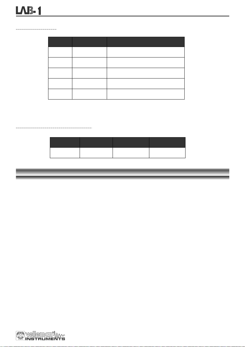
DC-voltage .................................................................................................................8
DC current..................................................................................................................8
AC voltage..................................................................................................................8
Diode & continuity ......................................................................................................8
Resistance..................................................................................................................9
Transisitor hFE Test (0-1000)....................................................................................9
DC voltage measurement..........................................................................................9
DC current measurement...........................................................................................9
AC voltage measurement ..........................................................................................9
Resistance..................................................................................................................9
Diode test .................................................................................................................10
Transistor Test.........................................................................................................10
Audible continuity test..............................................................................................10
3
Page 4
General
Thank you for buying this space saving lab solution unit.
We hope that this 3 in one unit will provide you years ease and practical use
.
In the box:
LAB1 three in one LAB device
Testing leads for DMM
Sponge
Spare bit for soldering iron
9V Battery for DMM
Mains cable
User manual
READ THE OPERATING AND MAINTENANCE INSTRUCTIONS IN
To all citizens of the European Union
Important environmental informa tion about this product
This symbol on this unit or the package indicates that disposal of this unit after its lifecycle
could harm the environment.
Do not dispose the unit (or batteries if used) as unsorted municipal waste; it should be
disposed by a specialized company for recycling.
This unit should be returned to your distributor or to a local recycling service.
Respect the local environmental rules.
Safety : General rules concerning safe use of our 3 in one unit.
To ensure your safet y, please observe these safet y measures. In no way these are complete. As safety
requirements vary, please check with your local authorities, in order to comply with local requirements.
If any doubt contact y our local authorities about waste disposal rules.
THIS US ER’S G UID E CAREFULLY.
WARRANTY
This product is guaranteed against defects in components and construction from the moment it is purchased and for a period of TWO
YEAR starting from the date of sale. This guarantee is only valid if the unit is submitted together with the origin al purc hase in voice.
VELLEMAN Ltd. limits its responsibility to the reparation of defects or, as VELLEMAN Ltd. deems necessary, to the replacement or
reparation of defective components. Costs and risks connected to the transport, removal or placement of the product, or any other costs
directly or indirectly connected to the repair, will not be reimbursed by VELLEMAN Ltd. VELLEMAN Ltd. will not be held responsible fo r
any damages caused by the malfunctioning of a unit.
4
Page 5
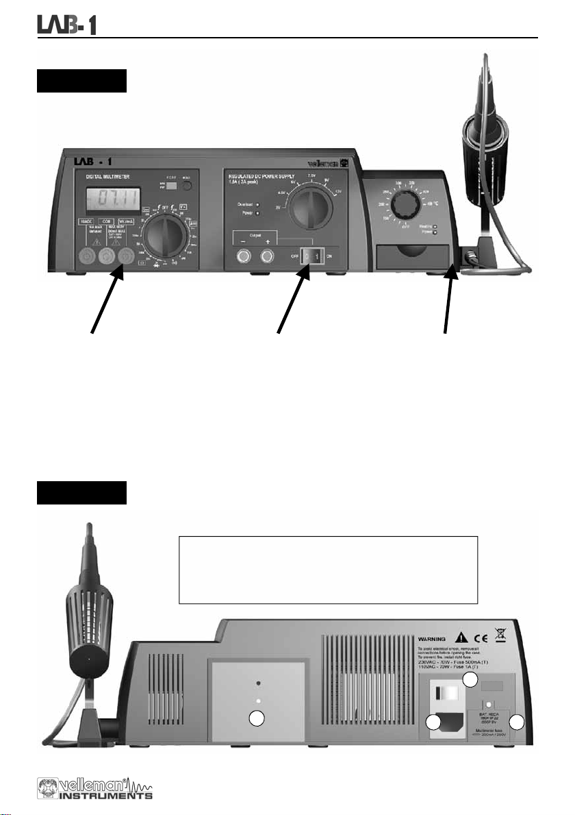
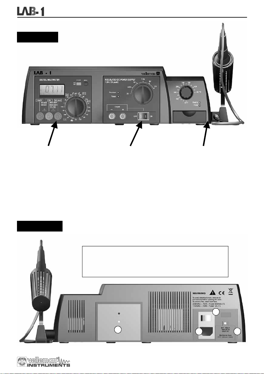
FRONT SIDE
General
DIGITAL MULTIMETER
3 1/2 backlit LCD
Automatic polarity indication
DC voltage 200mV to 600V in 5 steps
AC voltage 200V and 600V
DC current 200µA to 10A in 5 steps
Resistance test 200ohm to 2Mohm
Diode, transistor and continuity tester
Data Hold function and buzzer
CATI 600V
CATII 300V
REAR SIDE
1. Mains connector (check if unit complies with your local AC voltage)
2. Mains power switch, this switch provides power to the soldering
3. Multimeter battery compartment (see multimeter unit for more info)
4. Power supply heatsink, caution this plate can get hot.
REGULATED POWER SUPPLY
Selectable output voltages:
3 - 4.5 -6 - 7.5 - 9 - 12Vdc
Output 1.5A (2A peak)
LED overload indication
With output on/off switch
Very low ripple
LED power indication
station and the power supply
4
SOLDERING STATION
Low-voltage iron: 24V
Ceramic 48W heating element with
temperature sensor
Temperature range: OFF– 150 -450°C
Lead free soldering compatible
2
3 1
5
Page 6
Digital multimeter
DIGITAL MULTIMETER
SAFETY
1. SAFETY INFORMATION
This multimeter has been designed in accordance with IEC-1010. This norm pertains to electronic measuring
instruments that belong to an overvoltage category (CAT II 300V and CAT I 600V)
Follow all safety and operating instructions to ensure that the meter is used safely and is kept in good running order.
Full compliance with safety standards can only be guaranteed when the buyer uses the test leads supplied with this
packaging. If necessary, they should be replaced with identical leads.
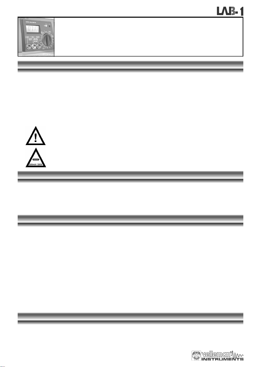
2. SAFETY SYMBOLS
MAINTENANCE
Before opening the case, always disconnect the test leads from all live circuits.
Avoiding fire risks : respect the specified voltage and current ratings when replacing the fuse (F 200mA / 250V)
(Quick acting)
Do not use the device unless all the covers are in place and securely fastened.
Do not apply abrasives or solvents to the meter. Use a damp cloth and mild detergent for cleaning purposes.
DURING USE
Important safety information, refer to the user manual.
Fuse should be replaced : the rating is specified in the manual.
Never exceed the limit value for protection. This limit value is listed separately in the specifications for each
range of measurement.
Do not touch unused terminals when the meter is linked to a circuit which is being tested.
Never use the meter with category I installations when measuring voltages that might exceed the safety margin
of 600V above earth ground.
Set the range selector at its highest position if the intensity of the tension or current to be measured is
completely unknown.
Disconnect the test leads from the tested circuit before rotating the range selector in order to change functions.
When carrying out measurements on a TV set or switching power circuits, always remember that the meter may
be damaged by any high amplitude voltage pulses at test points.
Always be careful when working with voltages above 60Vdc or 30Vac rms. Keep your fingers behind the probe
barriers at all times during measurement.
Before attempting to insert transistors for testing, always verify if the test leads have been disconnected.
Components should not be connected to the hFE socket while test leads are being used to execute voltage
measurements.
Never perform resistance measurements on live circuits.
DESCRIPTION
The device is a batter y-operated, 3 ½ digital multimeter for measuring DC and AC voltages, DC current and
resistance. It also offers the possibility of executing continuity tests and of testing diodes and transistors.
6
Page 7
Digital multimeter
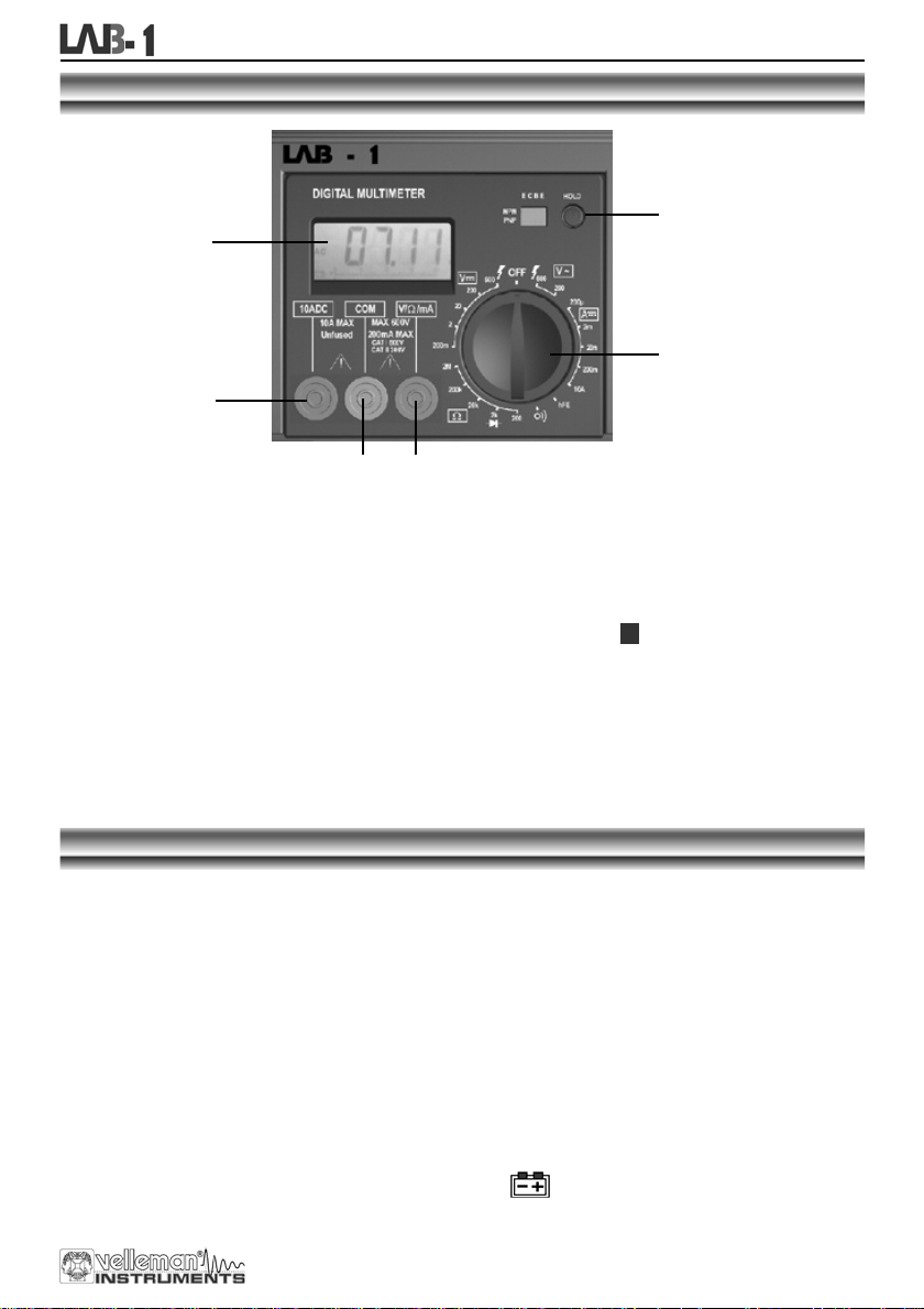
FRONTPANEL
3
1
2
4
5 6
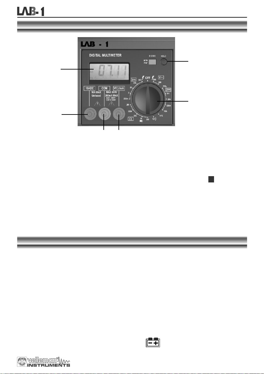
DESCRIPTION OF THE CONTROL PANEL :
1 Display with backlight (the backlight is only on when the complete unit is switched ON at the back)
3 ½ digits, 7 segments, LCD: 15mm high
2 Rotary switch
This switch is used to select functions and desired ranges as well as to turn the meter on/off.
3 Hold button
Upon pushing this button, the display will retain the last reading and the " "-symbol will remain on the
LCD until the button is pushed again.
4 "10A" jack
Insert the red test lead in this connector in order to measure a max. current of 10A.
5 "COM" jack
Insert the black (negative) test lead.
6 "VΩmA" jack
Insert the red (positive) test lead in this connector to measure voltage, resistance and current (except 10A).
H
SPECIFICATIONS
Maximum accuracy is achieved during a one- year period after calibration. T he ideal set of circumstances requires a
temperature of 18 to 28°C (64°F to 82°F) with a maximum relative humidity of 80%.
Maximum voltage between terminals and earth ground CAT I 600V or CAT II 300V
Fuse protection F 200mA / 250V
Power 9V battery
Display LCD, 1999 counts, updates 2-3/sec.
Measuring method Dual-slope integration A/D converter
Overrange indication Only figure "1" on the display
Polarity indication "-" displayed for negative polarity
Operating temperature 0 to 40°C
Storage temperature -10°C to 50°C
Low battery indication
" " appears on the display
7
Page 8

Digital multimeter
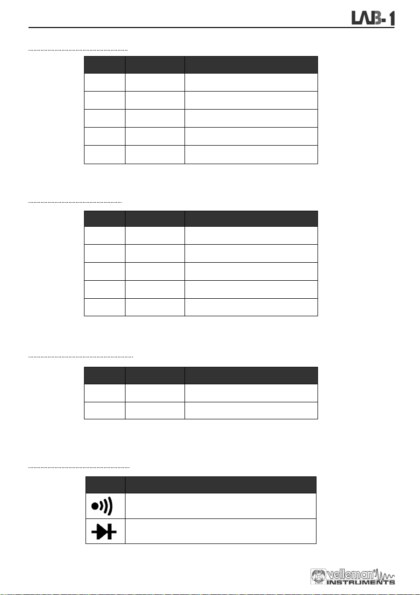
1. DC VOLTAGE
Range Resolution Accuracy
200mV 100µV ±0.5% of rdg ± 2 digits
2V 1mV ±0.5% of rdg ± 2 digits
20V 10mV ±0.5% of rdg ± 2 digits
200V 100mV ±0.5% of rdg ± 2 digits
600V 1V ±0.8% of rdg ± 2 digits
Overload protection : 250Vrms for the 200mV range and 600Vdc or rms ac for other ranges.
2. DC CURRENT
Range Resolution Accuracy
0.1µA
200µA
±1% of rdg ± 2 digits
2mA 1µA
20mA 10µA
200mA 100µA
10A 10mA
Overload protection : F 200mA / 250V fuse. (no fuse for the 10A range).
3. AC VOLTAGE
Range Resolution Accuracy
200V
100mV
600V 1V
Overload protection : 600Vdc or rms ac for all ranges.
Frequency range : 40Hz to 400Hz. Response : average, calibration in rms of a sine wave
4. DIODE & CONTINUITY
Range Description
If continuity exists (about less that 60Ω ), built-in buzzer
Displays the diode's approx. forward voltage drop
±1% of rdg ± 2 digits
±1% of rdg ± 2 digits
±1.5% of rdg ± 2 digits
±3% of rdg ± 2 digits
±1.2% of rdg ± 2 digits
±1.2% of rdg ± 2 digits
will sound
Overload protection : 250Vdc or rms ac
8
Page 9
5. RESISTANCE
Range Resolution Accuracy
200Ω
0.1Ω ±0.8% of rdg ± 2 digits
2kΩ 1Ω ±0.8% of rdg ± 2 digits
20kΩ 10Ω ±0.8% of rdg ± 2 digits
200kΩ 100Ω ±0.8% of rdg ± 2 digits
2MΩ 1kΩ ±1.0% of rdg ± 2 digits
Maximum open circuit voltage : 3.2V
Overload protection : 250Vdc or rms ac for all ranges.
6. TRANSISTOR hFE TEST (0-1000)
Range Tested range Tested current Tested voltage
Digital multimeter
NPN & PNP
0-1000 Ib = 10µA Vcd = 3V
OPERATING INSTRUCTIONS
1. DC VOLTAGE MEASUREMENT
1. Connect the red test lead to the "VΩmA" jack and the black lead to the "CO M" jack.
2. Set the rotary switch in the desired DCV position. If the voltage to be measured is unknown beforehand, you
should set the range switch in the highest range position and then reduce gradually until the ideal resolution
is obtained.
3. Connect the test leads to the source being measured.
4. Read the voltage value on the LCD display along with the polarity of the red lead connection.
2. DC CURRENT MEASUREMENT
1. Connect the red test lead to the "VΩmA" jack and the black test lead to the "COM" jack (switch the red lead
to the "10A" jack for measurements between 200mA and 10A).
2. Set the rotary switch (DCA) in the desired position.
3. Open the circuit in which the current is to be measured and connect the test leads to the circuit IN SERIES.
4. Read the current value and the polarity of the red lead connection on the LCD display
3. AC VOLTAGE MEASUREMENT
1. Connect the red test lead to the "VΩmA" jack and the black test lead to the "COM" jack.
2. Set the rotary switch in the appropriate ACV position.
3. Connect the test leads to the source to be measured.
4. Read the voltage value on the LCD display.
4. RESISTANCE
1. Connect the red test lead to the "VΩ mA" jack and the black test lead to the "COM" jack (the red lead has a
positive polarity "+").
2. Set the rotary switch in the appropriate "Ω " range position.
3. Connect the test leads to the resistor to be measured and read the LCD display.
4. If the resistance being measured is connected to a circuit, turn off the power and discharge all capacitors
before applying the test probes.
9
Page 10
Digital multimeter
5. DIODE TEST
1. Connect the red test lead to "VΩ mA" jack and the black one to the "COM" jack (the red lead has a positive
polarity "+".).
2. Set the rotary switch in the " " position.
3. Connect the red test lead to the anode of the diode to be tested and the black test lead to the cathode of the
diode. The approx. forward voltage drop of the diode will be displayed. If the connection is reversed, the
display will merely show a "1".
6. TRANSISTOR TEST
1. Set the rotary switch in the "hFE" position.
2. Determine whether the transistor under testing is NPN or PNP and locate the emitter, base and collector
leads. Insert the leads into the proper holes of the hFE-socket on the front panel.
3. Read the approximate hFE-value obtained under the following test conditions : a base current of 10µA and
Vce 3V.
7. AUDIBLE CONTINUITY TEST
1. Connect the red test lead to "VΩ mA" and the black one to "COM".
2. Set the range switch in the " " position.
3. Connect the test leads to two points of the circuit to be tested. If continuity exists, the built-in buzzer will
sound.
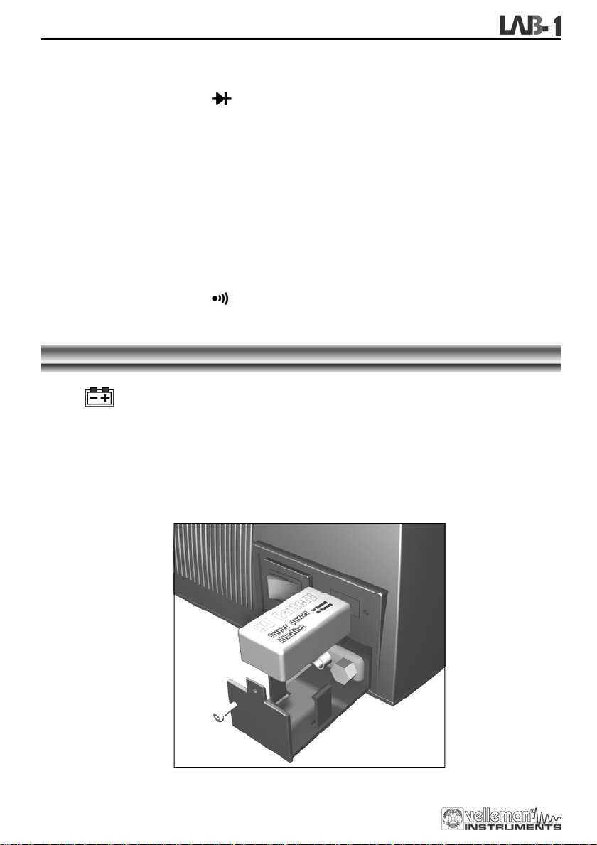
BATTERY & FUSE REPLACEMENT
When " " is displayed, the battery should be replaced.
To replace the battery simply remove the screw at the back of the case, slide out the battery compartment.
Remove the old specimen and insert the new one.
Please remember to observe battery polarity.
10
Page 11
Digital multimeter
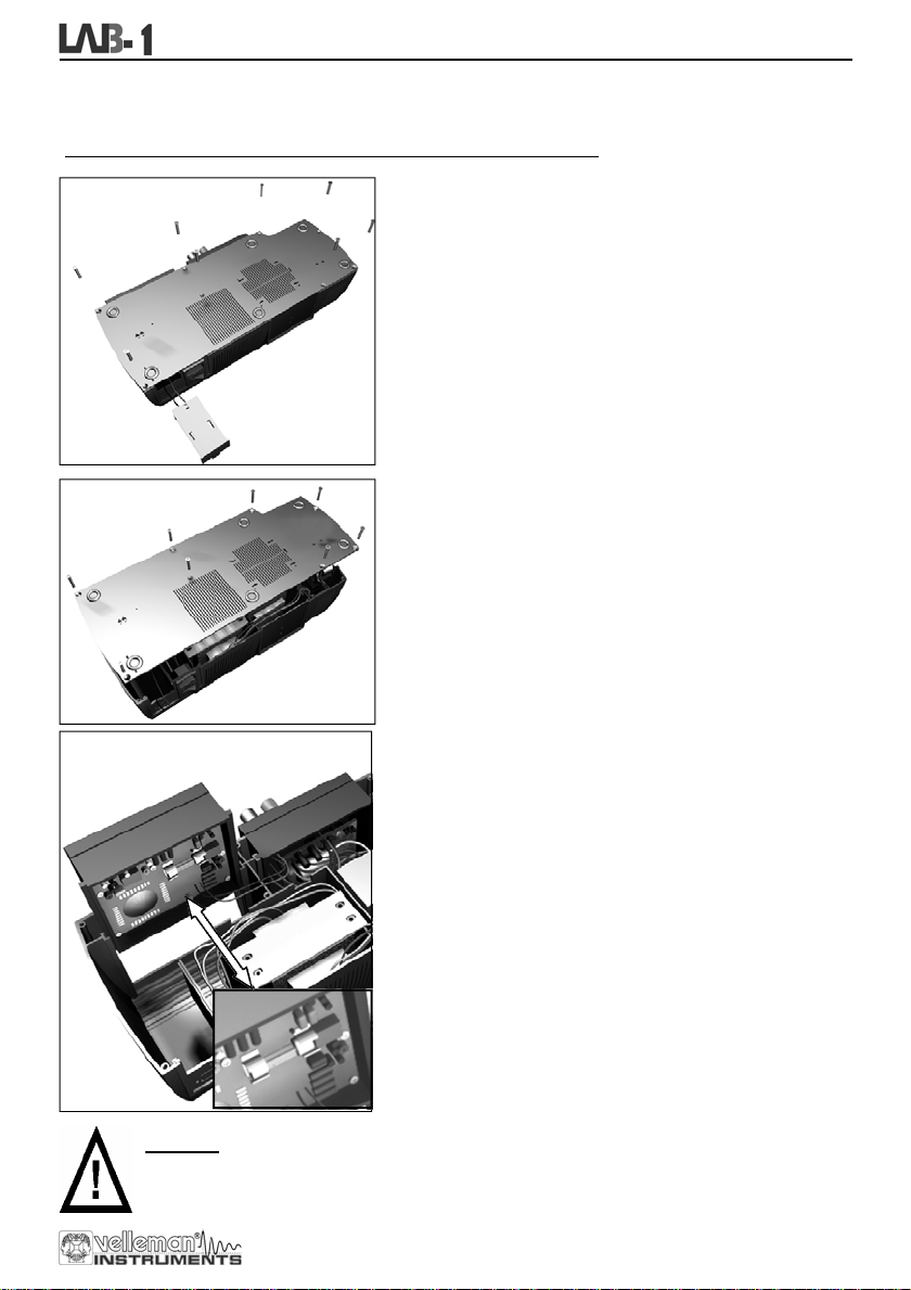
When the fuse is blown it will have to be replaced for the device to work again.
Follow the procedure below to replace the protective fuse (200mA / 250V):
Step 1 :
Remove the battery compartment and the screws of the
bottom plate (see figure)
Step 2 :
Remove the entire bottom plate.
Step 3 :
Slide out the meter module to facilitate access to the fuse
compartment.
Replace the fuse with a similar type 200mA /250V fuse type
(quick-acting)
Step 4 :
Slide the meter module back into place, replace the bottom
plate and fix it with the screws, then slide the battery
compartment back into place.
WARNING
Befor e a tte m pt ing to op e n the ca se , ver i fy i f th e tes t lea ds h a ve bee n disc o n nec te d. B e fore us i ng th e
meter, please remember to close the case and tighten the screws properly in order to avoid
electroshocks.
The unit is now ready for use.
11
Page 12
Regulated power supply
REGULATED POWER
SUPPLY
INTRODUCTION
The power unit is a very accurate, DC regulated power supply with a selectable output voltage: 3V, 4.5V, 6V, 7.5V,
9V, 12V. The rated output current is 1.5A and the peak current is 2A.
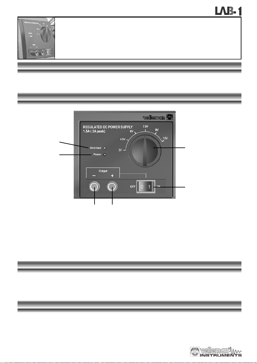
FRONTPANEL
6
2
5
1
3 4
DESCRIPTION OF THE CONTROL PANEL
1. Output ON/OFF switch
2. Power indicator
3. Output (-) terminal
4. Output (+) terminal
5. Dial
6. LED overload indication
:
USE
Turn on the main power switch at the back of the unit; the power indication should lit (2)
Select the output voltage with the dial (5). Connect the positive input terminal of your device with the output (+)
terminal (4) and connect the negative input terminal with the output (-) terminal (3).
Using the output ON/OFF switch (1) you can disconnect your application from the power supply.
ATTENTION
The overload LED will lit if the output current exceeds the supply specifications
Do not turn the dial (5) while the device is in use.
12
Page 13
Soldering station
SOLDERING STATION
INTRODUCTION
This soldering station is temperature-controlled: sophisticated circuitry regulates the temperature between 150°C
and 450°C.
The unit is a 48W soldering station with a temperature sensor in the ceramic heating element. The heating element
is supplied with the necessary power via a safe 24V transformer, while the bit is completely isolated from the mains.
The control circuitry ensures that devices sensitive to static charges cannot be damaged during the soldering
process. The included bit consists of a copper core that is protected by a steel coating.
FRONTPANEL
4
2
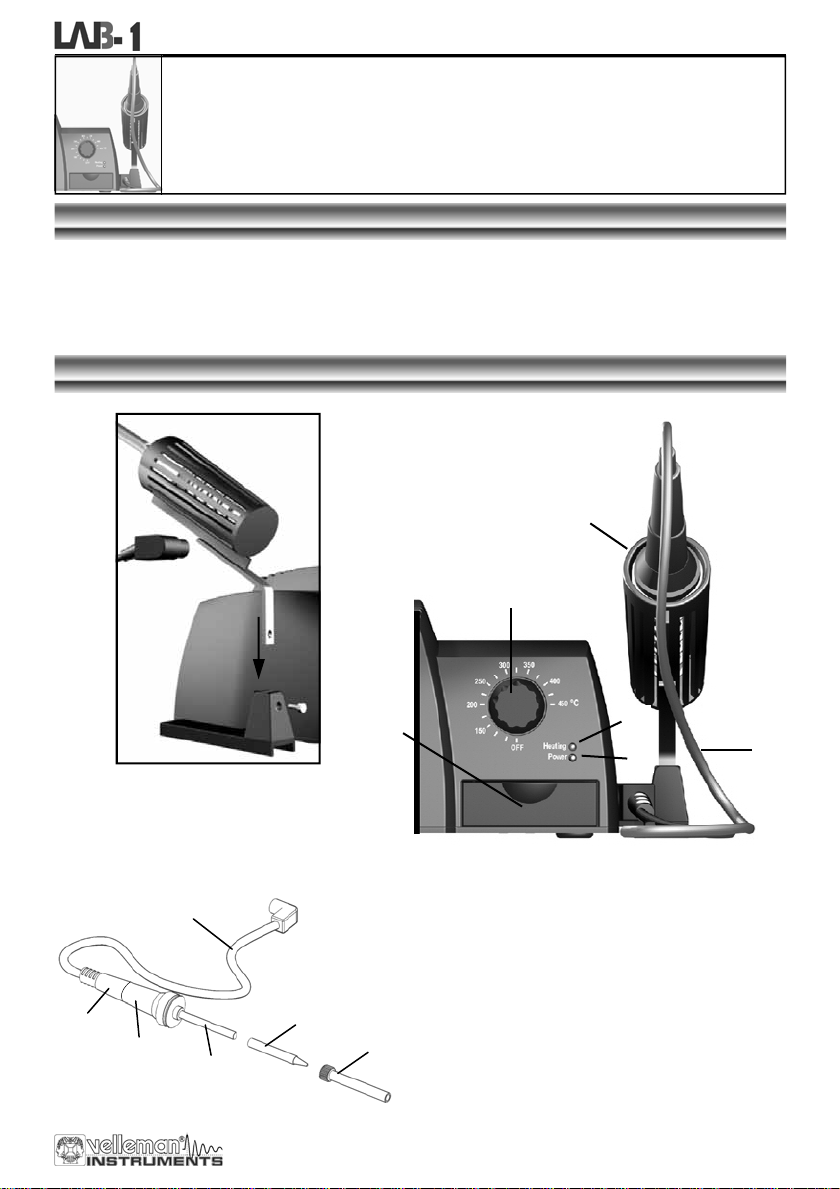
BEFORE USE, INSERT THE SOLDERING IRON
HOLDER IN THE BASE AND TIGHTEN IT WITH
THE INCLUDED SCREW
1
8
9
10
5
3
DESCRIPTION OF THE CONTROL PANEL
1. Heat safe rubber cable
2. Temperature control
3. Tray with sponge
4. Iron stand (fixed to main unit)
5. Bit
6. Bit holder
7. Heating indication LED
8. Handle
6
9. Antiskid rubber
10. Heating element with incorporated temperature
sensor
11. Power indication LED
7
11
1
13
Page 14
Soldering station
WORKING TEMPERATURE
Turn on the complete unit with mains switch on the back, the power indication LED (11) should lit. A well-chosen temperature is essential for efficient soldering. Solder does not flow well when the temperature is too low and this leads to weak
soldering. The flux in the solder evaporates when the tem perature is too high, not giving the solder sufficient time to flow
and possibly damaging the components. The correct temperature and the correct soldering technique practically guarantee a good result. The most c ommon solder alloy consists of 60% of tin (Sn) and 40% of lead (Pb). New lead free solder
consists of 99.7% Tin (Sn) and 0.3% Copper (Cu) or 96% Tin (Sn) and 4% Silver (Ag). If the set temperature is rising, the
“heating LED” (7) will lit, as soon as the temperature is reached, the LED will blink.
For Lead containing soldering a tip temperature of about 250 to 350°C is recommended.
For Lead free soldering a tip temperature between 350 to 400°c is recommended.
It is advisable to use lead containing solder to repair lead containing solderings.
Make sure to turn the temperature control to OFF if the soldering station is not used for long time.
TIPS
ALWAYS KEEP THE SPONGE WET (water only).
Wipe the bit clean before use and keep the tip tinned when the device is not being used.
Prolonged use at high temperatures causes the bit to wear prematurely
Never clean the bit with a file or abrasive materials.
Corrosion on the bit can be removed with very fine emery cloth (600 – 800) or with isopropyl alcohol. Heat and tin
the bit immediately after cleaning
Remove and clean the bit after 20 hours of usage (or at least once a week) to avoid corrosion
Do not use corrosive flux or flux containing chlorine. Resinous flux is safe.
MAINTENANCE
Let the bit cool down before cleaning or replacing it. You can remove the bit by loosening the nut on the bit holder.
Clean the bit holder next by blowing into it forcefully. Do not forget to protect your eyes !
Put the bit back in place and tighten the nut. Wipe clean the rest of the iron and the soldering station with a damp
cloth. Do not use sol vents and make sure no liquid penetrates the housing of the device.
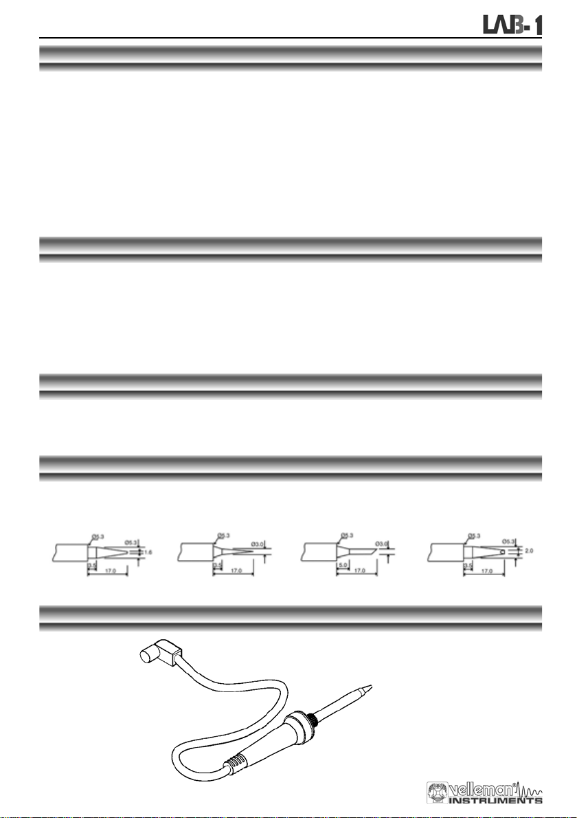
SPAR E BI TS (s iz e de pendant )
BITC10N1 : 1.6mm round BITC10N2 : 0.8mm round
BITC10N3 : 3.0mm slant-
edged
BITC10N4 : 2.0mm
pointed & slant-edged
SPARE SOLDERING IRON
LAB1SCS
14
Page 15

Inhoud
INHOUD
Algemeen ..................................................................................................................................................................16
In de doos ....................................................................................................................................................16
Veiligheid & waarschuwingen ......................................................................................................................16
Waarborg .....................................................................................................................................................16
Overzicht van de voorzijde ..........................................................................................................................17
Overzicht van de achterzijde .......................................................................................................................17
Digitale multimeter...................................................................................................................................................18
Veiligheid......................................................................................................................................................18
Onderhoud ...................................................................................................................................................18
Tijdens gebruik ............................................................................................................................................18
Algemene omschrijving................................................................................................................................18
Voorzijde ......................................................................................................................................................19
Specificaties .................................................................................................................................................19
Bedieningsinstructies...................................................................................................................................21
Batterij & zekering vervangen......................................................................................................................22
Gestabiliseerde voeding .........................................................................................................................................24
Inleiding........................................................................................................................................................24
Overzicht van de voorzijde ..........................................................................................................................24
Gebruik.........................................................................................................................................................24
Opgelet.........................................................................................................................................................24
Soldeerstation ..........................................................................................................................................................25
Beschrijving..................................................................................................................................................25
Overzicht van de voorzijde ..........................................................................................................................25
Bedrijfstemperatuur......................................................................................................................................26
Tips ..............................................................................................................................................................26
Onderhoud ...................................................................................................................................................26
Reservestiften ..............................................................................................................................................26
Reservesoldeerbout .....................................................................................................................................26
Gelijkspanning (DC).................................................................................................20
Gelijkstroom (DC).....................................................................................................20
Wisselspanning (AC)................................................................................................20
Diode & continuiteit..................................................................................................20
Weerstand................................................................................................................21
Transistor hFE Test (0-1000)...................................................................................21
Gelijkspanning meten...............................................................................................21
Gelijkstroom meten ..................................................................................................21
Wisselspanning meten.............................................................................................21
Weerstand................................................................................................................21
Diodentest ................................................................................................................22
Transistortest ...........................................................................................................22
Hoorbare continuiteittest..........................................................................................22
15
Page 16
Algemeen
Dank u voor uw aankoop van deze ruimtebesparende laboplossing.
Wij hopen dat dit 3-in-1 toestel u jaren gebruiksgemak zal bezorgen.
In de doos :
LAB1 "3 in 1 LABO toestel"
Testsnoeren voor de digitale multimeter "DMM"
Spons
Reservestift voor soldeerstation
9V Batterij voor de digitale multimeter "DMM"
Netsnoer
Gebruikershandleiding
LEES DE GEBRUIKS - EN ONDERHOUDSAANWIJZINGEN VAN
Aan alle ingezetenen van de Europese Unie
Belangrijke milieu-informatie betreffende dit product
Dit symbool op het toestel of de verpakking geeft aan dat, als het na zijn levens-cyclus
wordt weggeworpen, dit toestel schade kan toebrengen aan het milieu. Gooi dit toestel (en
eventuele batterijen) niet bij het gewone huishoudelijke afval; het moet bij een
gespecialiseerd bedrijf terechtkomen voor recyclage. U dient dit toestel naar uw verdeler of
naar een lokaal recyclagepunt te brengen. Respecteer de plaatselijke milieuwetgeving.
Heeft u vragen, contacteer dan de plaatselijke autoriteiten inzake afvalverwijdering.
Veiligheid: algemene regels om onz e Kit s of Mo dules v eilig te gebruiken . Hou rekening m et d eze aan bevelingen, ze zijn belangrijk voor Uw veiligheid. In geen geval zijn deze richtlijnen kompleet. Vermits de
veiligheids v ereisten verschillen van plaats to t plaats, dient U ervoor te zorgen dat Uw montag e voldoet
aan de plaatselijk geldende vereisten. Dit logo staat op toestellen waarin dodelijke spanningen kunnen
voorkomen. Wees voorzichtig!
DE HANDLEIDING ZORGVULDIG DOOR.
WAARBORG
Dit produkt is gewaarborgd wat betreft gebreken in materialen en vakmanschap op het ogenblik van de aankoop en dit gedurende een
periode van TWEE JAAR vanaf de aankoop. De waarborg geldt enkel indien het produkt voorgelegd wordt samen met het origineel
aankoop bewijs. De verpli chtingen van VELLEMAN N.V. beperken zich tot het herstellen van defecten of, naar vrije keuze van
VELLEMAN N.V. tot het vervangen of herstellen van defecte onderdelen. Kosten en risico’s van transport; het wegnemen en
terugplaatsen van het produkt, evenals om het even welke andere kosten die rechtstreeks of onrechtstreeks verband houden met de
herstelling, worden niet door VELLEMAN N.V. vergoed. VELLEMAN N.V. is niet verantwoordelijk voor schade van gelijk welke aard,
veroorzaakt door het falen van een product.
16
Page 17
VOORZIJDE
General
DIGITALE MULTIMETER
3 ½" LCD met achtergrondverlichting
Automatische polariteitweergave
DC-spanning 200mV tot 600V in 5
stappen
AC-spanning 200V en 600V
DC-spanning 200µA tot 10A in 5
stappen
Weerstandtest 200ohm tot 2Mohm
Diode-, transistor- en continuïteitstest
'Data Hold'-functie en buzzer
CATI 600V
CATII 300V
ACHTERZIJDE
1. Netvoeding aansl uiting (ga na of uw toes tel overeen komt met de lokale
2. Hoofdschakelaar: deze schakelt het soldeerstation en de voedi ng in
3. Batterijvak multimeter (zie "multimeter-gedeelte" voor meer informatie)
4. Koelplaat voor de voeding ; let op: deze plaat kan heet worden!
GESTABILISEERDE VOEDING
Instelbare uitgangsspanning:
3 - 4.5 -6 - 7.5 - 9 - 12Vdc
Uitgang 1.5A (2A piek)
LED-aanduiding bij overbelasting
Uitgang met on/off schakelaar
Zeer lage rimpel
LED-aanduiding of het toestel
ingeschakeld is
AC-spanning)
4
SOLDEERSTATION
Soldeerbout op lage spanning: 24V
Keramisch 48W verwarmingselement
met temperatuursensor
Temperatuurbereik: OFF– 150 -450°C
Loodvrij solderen mogelijk
2
3 1
17
Page 18

Digitale multimeter
DIGITALE
MULTIMETER
VEILIGHEID
1. VEILIGHEIDSVOORSCHRIFTEN
Deze multimeter werd ontworpen in overeenstemming met de IEC-1010-norm. Deze norm heeft betrekking op
elektronische meetinstrumenten die tot een overvoltagecategorie (CAT II 300V en CAT I 600V) behoren. Volg
nauwgezet alle veiligheids- en bedieningsvoorschriften op. Enkel dan houdt u uw multimeter bedrijfsklaar en kunt u
er zeker van zijn dat u hem op een veilige manier gebruikt.
U voldoet enkel aan de veiligheidsvoorschriften indien u de meegeleverde testsnoeren gebruikt. Zo nodig moet u ze
vervangen door de identieke snoeren.
2. VEILIGHEIDSSYMBOLEN
Belangrijke info i.v.m. de veiligheid, zie gebruikershandleiding.
Zekering vervangen : het type is vermeld in de handleiding.
ONDERHOUD
Voordat u de behuizing openmaakt, moet u controleren of er nog testsnoeren aangesloten zijn op schakelingen die
onder stroom staan.
Vermijden van brandrisico's : respecteer de maximale voltage- en stroomniveaus wanneer u de zekering vervangt (F 200mA /
250V - snelwerkend)
Gebruik de meter nooit met open batterijdeksel.
Reinig de meter enkel met een vochtige doek en een zachte detergent. Gebruik nooit agressieve schuur- of oplosmiddelen.
TIJDENS GEBRUIK
Overschrijd nooit de grenswaarden. Deze waarden worden telkens apart vermeld in de specificaties van elk meetbereik.
Raak geen ongebruikte ingangsbussen aan wanneer de meter gekoppeld is aan een schakeling die u aan het testen bent.
Gebruik de meter nooit voor categorie II-installaties wanneer u voltages aan het meten bent die de veiligheidsmarge
van 600V boven het massapotentiaal (kunnen) overschrijden.
Zet de bereikregelaar op de hoogste stand als de te meten spanning of stroom helemaal ongekend is.
Koppel de testsnoeren los van de geteste schakeling voordat u een andere functie kiest d.m.v. de keuzeschakelaar.
Wanneer u metingen uitvoert op een TV of een schakelende voeding, mag u niet vergeten dat een sterke stroomstoot
ter hoogte van de geteste punten de meter kan beschadigen.
Wees uiterst voorzichtig wanneer u werkt met voltages boven 60Vdc of 30Vac rms.Tijdens uw metingen moet u uw
vingers te allen tijde achter de meetpennen houden.
Voordat u transistors aansluit om ze te testen, moet u nagaan of alle testsnoeren wel degelijk losgekoppeld zijn.
Sluit nooit componenten aan op de hFE-connector terwijl u spanningsmetingen aan het uitvoeren bent d.m.v.
testsnoeren.
Voer nooit weerstandsmetingen uit op schakelingen die onder stroom staan.
Never perform resistance measurements on live circuits.
ALGEMEN E OMS C H RIJVING
Deze module is een batterijgestuurde, handbediende 3 ½-digit digitale multimeter. Met dit apparaat kunt u
weerstanden, gelijk- en wisselspanning en gelijkstroom meten. U kunt continuïteitstesten uitvoeren en u kunt er
zelfs dioden en transistors mee testen.
18
Page 19
Digitale multimeter
VOORZIJDE
3
1
2
4
5 6
BESCHRIJVING VAN HET INSTRUMENTENBORD :
1. Scherm met achtergrondverlichting (de achtergrondverlichting brandt alleen als het hele toestel
ingeschakeld is met de schakelaar op de achterkant) 3 ½ digits, 7 segmenten, LCD: 15mm hoog.
2 Draaiknop
Wordt gebruikt om de gewenste functie en het bereik in te stellen. Doet ook dienst als voedingsschakelaar (ON/OFF).
3 Hold - toets
Wanneer u deze knop indrukt, zal het uitleesvenster de laatste waarde vasthouden. Het " " -symbool
blijft op de LCD tot u de knop opnieuw indrukt.
4 "10A" jack
Wanneer u het rode testsnoer aansluit op deze connector, kunt u een max. stroom meten van 10A..
5 "COM" jack
Sluit het zwarte (negatieve) testsnoer aan.
6 "VΩmA" jack
Sluit het rode (positieve) testsnoer aan op deze connector. U kunt nu spanning, weerstand en stroom meten
(uitgez. 10A).
H
SPECIFICATIES
Tot één jaar na de ijking mag u optimale nauwkeurigheid verwachten.Ideale weersomstandigheden zijn : een
temperatuur van 18 tot 28°C met een relatieve vochtigheidsgraad van max. 80%.
Maximale spanning tussen de ingangsbussen en de
aarding
Beveiliging van de zekering
F 200mA / 250V
Voeding 9V batterij
Display LCD, 1999 punten, updates 2-3/sec.
Meetmethode Dual-slope integration A/D convertor
Buiten-bereik indicatie Enkel cijfer "1" op de display
Polariteitsindicatie "-" op de display (negatieve polariteit)
Werktemperatuur 0 tot 40°C
Opslagtemperatuur -10°C tot 50°C
Batterij-leeg indicatie
CAT I 600V of CAT II 300V
" " verschijnt op de display
19
Page 20
Digitale multimeter
1. GELIJKSPANNING (DC)
Range Resolution Accuracy
200mV 100µV ±0.5% of rdg ± 2 digits
2V 1mV ±0.5% of rdg ± 2 digits
20V 10mV ±0.5% of rdg ± 2 digits
200V 100mV ±0.5% of rdg ± 2 digits
600V 1V ±0.8% of rdg ± 2 digits
Beveiliging tegen overbelasting : 250Vrms voor het 200mV-bereik en 600Vdc of rms ac voor elk ander bereik.
2. GELIJKSTROOM (DC)
Bereik Resolutie Nauwkeurigheid
0.1µA
200µA
±1% uitlezing ± 2 digits
2mA 1µA
20mA 10µA
200mA 100µA
10A 10mA
Beveiliging tegen overbelasting : F 200mA / 250V zekering. (geen zekering voor het 10A-bereik).
3. WISSELSPANNING (AC)
Bereik Resolutie Nauwkeurigheid
200V
100mV
600V 1V
Beveiliging tegen overbelasting : 600Vdc of rms ac voor elk bereik.
Frequentiebereik : 40Hz tot 400Hz. Respons : gemiddeld, ijking in rms van de sinuslijn.
4. DIODE & CONTINUITEIT
Bereik Omschrijvingn
Als er continuïteit is (<60Ω), gaat de ingebouwde buzzer
Op de display verschijnt het voorwaartse spanningsverlies
±1% uitlezing ± 2 digits
±1% uitlezing ± 2 digits
±1.5% uitlezing ± 2 digits
±3% uitlezing ± 2 digits
±1.2% uitlezing ± 2 digits
±1.2% uitlezing ± 2 digits
af
van de diode
Beveiliging tegen overbelasting : 250Vdc of rms ac
20
Page 21

5. WEERSTAND
Digitale multimeter
Bereik Resolutie Nauwkeurigheid
200Ω
0.1Ω
1Ω
2kΩ
10Ω
20kΩ
100Ω
200kΩ
1kΩ
2MΩ
Max. spanning open schakeling : 3.2V
Beveiliging tegen overbelasting : 250Vdc of rms ac voor elk bereik.
6. TRANSISTOR hFE TEST (0-1000)
Bereik Testbereik Teststroom Testspanning
NPN & PNP
0-1000 Ib = 10µA Vcd = 3V
±0.8% uitlezing ± 2 digits
±0.8% uitlezing ± 2 digits
±0.8% uitlezing ± 2 digits
±0.8% uitlezing ± 2 digits
±1.0% uitlezing ± 2 digits
BEDIENINGSINSTRUCTIES
1. GELIJKSPANNING METEN
1. Verbind het rode testsnoer met de "VΩmA"-aansluiting en het zwarte testsnoer met de "COM"-aansluiting.
2. Stel het gewenste meetbereik in d.m.v. de draaiknop. Stel de functieschakelaar in op het grootste bereik
indien de te meten gelijkspanning niet vooraf gekend is en verminder dan geleidelijk om de ideale resolutie
te bepalen.
3. Verbind de meetsnoeren met de schakeling.
4. U kunt nu de intensiteit van de spanning en de polariteit van het rode testsnoer aflezen op de LCD-display.
2. GELIJKSTROOM METEN
1. Verbind het rode testsnoer met de "VΩmA"-aansluiting en het zwarte testsnoer met de "COM"-aansluiting
(stop het rode snoer in de "10A"-aansluiting voor metingen tussen 200mA en 10A).
2. Stel het gewenste meetbereik in d.m.v. de draaiknop (DCA).
3. Verbind de meetsnoeren IN SERIE met de schakeling waar van u de belasting wilt meten.
4. U kunt nu de stroomwaarde en de polariteit van het rode meetsnoer aflezen op de LCD-display
3. WISSELSPANNING METEN
1. Verbind het rode testsnoer met de "VΩmA"-aansluiting en het zwarte testsnoer met de "COM"-aansluiting.
2. Stel het gewenste meetbereik in d.m.v. de draaiknop (ACV).
3. Verbind de meetsnoeren met de schakeling.
4. Lees de intensiteit van de spanning af op de LCD-display.
4. WEERSTAND
1. Verbind het rode testsnoer met de "VΩ mA"-aansluiting en het zwarte testsnoer met de "COM"-aansluiting
(het rode snoer heeft een positieve polariteit"+").
2. Plaats de functieschakelaar in de gewenste stand ("Ω ").
3. Verbind de meetsnoeren met de weerstand en lees de LCD-display.
4. Zorg ervoor dat bij weerstandsmetingen geen spanning meer op de schakeling staat en dat alle
condensatoren volledig ontladen zijn.
21
Page 22

Digitale multimeter
5. DIODENTEST
1. Verbind het rode testsnoer met de "VΩmA"-aansluiting en het zwarte testsnoer met de "COM"-aansluiting
(het rode snoer heeft een positieve polariteit"+").
2. Plaats de functieschakelaar in de gewenste stand (" ").
3. Verbind het rode meetsnoer met de anode van de diode in kwestie en verbind het zwarte meetsnoer met de
kathode van de diode. Het voorwaartse spanningsverlies van de diode verschijnt nu op uw display. Wordt
de schakeling omgedraaid, dan verschijnt enkel het cijfer "1" op uw display.
6. TRANSISTORTEST
1. Plaats de functieschakelaar in de "hFE"-stand.
2. Bepaal of het om een NPN- of PNP-transistor gaat en lokaliseer de zender, de basis en de collector. Stop
de snoeren in de overeenkomstige openingen van de hFE-connector op het frontpaneel.
3. Lees de benaderende hFE-waarde op uw display. Testomstandigheden : basisstroom van 10µA en een
collector-emitterspanning (Vce) van 3V.
7. HOORBARE CONTINUITEITSTEST
1. Verbind het rode meetsnoer met "VΩmA"en het zwarte met "COM".
2. Plaats de functieschakelaar in de " "-stand.
3. Verbind de testsnoeren met twee punten van de schakeling die u wilt testen. De ingebouwde buzzer zal in
BATTERIJ & ZEKERING VERVANGEN
Wanneer u het " "-symbool op uw display vindt, is de batterij aan vervanging toe
Om de batterij te vervangen, verwijdert u de schroef achteraan het toestel en schuift u het batterijvak eruit.
Verwijder het oude exemplaar en breng het nieuwe in.
Verlies de polariteit van de ba tterij niet uit het oog !
22
Page 23

Digitale multimeter
Als de zekering van de multimeter springt dan functioneert het toestel
niet meer tot de zekering is vervangen.
Volg deze procedure om de veiligheidszekering te vervangen (200mA / 250V):
Stap 1 :
Verwijder het batterijvak en de schroeven van de bodemplaat
(zie figuur).
Stap 2 :
Neem de volledige bodemplaat weg.
Stap 3 :
Verwijder de metermodule zodat u makkelijker bij het
compartiment van de zekering kunt.
Vervang de zekering door een gelijkaardige 200mA /250V
zekering (quick-acting)
Stap 4 :
Schuif de metermodule weer op z'n plaats, breng de
bodemplaat weer aan en schroef ze vast. Schuif het
batterijvak weer op z'n plaats.
WAARSCHUWING
Maak eerst alle meetsnoeren los voor u de meter openmaakt. Zorg ervoor dat de meter stevig
dichtgeschroefd is voor u hem gebruikt. Zo bent u beveiligd tegen elektroshocks.
Het toestel is nu gebruiksklaar.
23
Page 24

Gestabiliseerde voeding
GESTABILISEERDE
VOEDING
INLEIDING
Deze module is een zeer precieze, DC-gestabiliseerde voeding met een selecteerbare uitgangsspanning: 3V, 4.5V,
6V, 7.5V, 9V, 12V. De max. uitgangsstroom bedraagt 1.5A en de piek stroom bedraagt 2A.
VOORZIJDE
6
2
5
1
3 4
BESCHRIJVING VAN HET INSTRUMENTENBORD :
1. ON/OFF schakelaar
2. Voedingsindicator
3. Uitgangsjack (-)
4. Uitgangsjack (+)
5. Draaiknop
6. LED die overbelasting aangeeft
GEBRUIK
Schakel het toestel in d.m.v. de schakelaar op de achterzijde van het toestel ; de VoedingLED (2) zou moeten
oplichten. Selecteer de uitgangsspanning met de draaiknop (5).
Verbind de positieve ingangsaansluiting van uw toestel met de (+) aansluitklem (4) van de voedingsmodule en
verbind de negatieve ingangsaansluiting met de (-) aansluitklem (3) van de voedingsmodule. Met de AAN/UIT
schakelaar (1) kan men het toestel met de netspanning verbreken.
OPGELET
De overbelastingsLED zal oplichten wanneer de uitgaande stroom hoger ligt dan de specificaties van de voeding.
Draai niet aan de draaiknop (5) terwijl het toestel in werking is.
24
Page 25

Soldeerstation
SOLDEERSTATION
BESCHRIJVING
Dit soldeerstation is temperatuurgestuurd : een gesofisticeerde schakeling r egelt de temperatuur tussen 150°C en 450° C.
Deze modul e is een soldeerstation van 48W met een temperatuursensor in het keramisch verwarmingselement. Het
verwarmingselement wordt gevoed via een veilige transformator van 24V en de stift is volledig gescheiden van het net. De
elektronische sturing zor gt ervoor dat toestellen die gevoelig zijn voor statische ontladingen niet worden beschadigd
tijdens het solderen. De meegeleverde stift bestaat uit een koperen kern die wordt beschermd door een s talen mantel.
VOORZIJDE
4
2
VOOR GEBRUIK: STOP DE SOLDEERBOUTHOUDER IN DE VOET EN SPAN HET GEHEEL
AAN MET DE SCHROEF.
1
8
9
10
5
3
BESCHRIJVING VAN HET INSTRUMENTENBORD :
1. Hittebestendige rubber kabel
2. Temperatuurregeling
3. Schuifje met spons
4. IJzeren houder (vast aan de behuizing)
5. Stift
6. Stifthouder
7. LED die aangeeft dat de soldeerbout opwarmt
8. Handvat
6
9. Antislip rubber
10. Verwarmingselement met ingebouwde
temperatuursensor
11. VoedingLED
7
11
1
25
Page 26

Soldeerstation
BEDRIJFSTEMPERATUUR
Schakel het toestel in d.m.v. de schakelaar op de achterzijde van het toestel ; de VoedingLED (11) zou moeten oplichten.
Een goed gekozen tem peratuur is essentieel voor een goed resultaat. Soldeer vloeit niet goed bij een te lage temperatuur
zodat de naad niet goed kan worden gelast. Bij een te hoge temperatuur verdampt het vloeimiddel in het soldeer, zodat
het soldeer onvoldoende tijd heeft om te vloeien. Bovendien kunnen de bewerkte componenten schade oplopen. Een
goed resultaat is nagenoeg gegarandeerd wanneer u de juiste tec hniek en de j uiste temperatuur gebruikt. De meest
gebruikte soldeerlegering bestaat voor 60% uit tin (Sn) en voor 40% uit lood (Pb). Nieuw loodvrij soldeertin bestaat uit
99.7% tin (Sn) en 0.3% koper (Cu) of 96% tin (Sn) en 4% zil ver (Ag). .De temperatuur LED (7) licht op wanneer de
temperatuur begint te stijgen en knippert wanneer de ingestelde temperatuur is ber eikt
Voor loodhoudend solderen is een temperatuur van 250 tot 350°C aanbevolen.
Voor loodvrij solderen is een temperatuur van 350 tot 400°C aanbevolen.
Het is raadzaam om loodhoudend soldeertin te gebruiken voor loodhoudende solderingen te herstellen.
Let erop dat u de temperatuurregelaar op OFF zet als het soldeerstation lange tijd niet zal worden gebruikt.
TIPS
HOU DE SPONS ALTIJD VOCHTIG (uitsluitend met water).
Veeg de stift schoon voor gebruik en vertin de stift wanneer u het toestel niet wordt gebruikt.
Door langdurig gebruik op hoge temperatuur zal de soldeertip sneller verslijten.
Reinig de stift nooit met een vijl of met schurende materialen.
Verwijder sporen van corrosie op de stift met fijn schuurlinnen (600 – 800) of met isopropylalcohol. Verwarm en
vertin de stift onmiddellijk na reiniging.
Verwijder en reinig de stift na elke 20 uren gebruik (of minimum 1 x per week) om corrosie te vermijden
Gebruik geen chloorhoudende of bijtende vloeimiddelen. Harshoudende vloeimiddelen zijn veilig.
ONDERHOUD
Laat de stift afkoelen voor u hem vervangt of reinigt. Draai de moer van de stifthouder los om de stift te verwijderen. Maak
vervolgens de stifthouder schoon door erin te blazen maar vergeet niet om hierbij uw ogen te beschermen. Breng de stift
terug op zijn plaats en span de moer aan. Veeg de rest van de soldeerbout en het s oldeerstation schoon met een vochtige
doek. Gebrui k geen solventen en waak erover dat geen enkele vloeistof de behuizing van het toestel binnendringt.
RESERVESTIFTEN
BITC10N1 : rond 1.6mm BITC10N2 : rond 0.8mm
BITC10N3 : 3.0mm
afgeschuind
BITC10N4 : 2.0mm punt
& afgeschuind
RESERVESOLDEERBOUT
LAB1SCS
26
Page 27

Sommaire
SOMMAIRE
Generalites................................................................................................................................................................28
Dans la boîte ................................................................................................................................................28
Sécurité et mises en gard............................................................................................................................28
Garantie .......................................................................................................................................................28
Aperçu de face avant ...................................................................................................................................29
Aperçu de face arrière .................................................................................................................................29
Multimètre numérique .............................................................................................................................................30
Sécurité ........................................................................................................................................................30
Entretien.......................................................................................................................................................30
Emploi ..........................................................................................................................................................30
Description générale....................................................................................................................................30
Panneau frontal............................................................................................................................................31
Spécifications ...............................................................................................................................................31
Instructions de commande...........................................................................................................................33
Remplacement de batterie et fusible ...........................................................................................................34
Alimentation stabilisée............................................................................................................................................36
Introduction ..................................................................................................................................................36
Panneau frontal............................................................................................................................................36
Opération .....................................................................................................................................................36
Attention .......................................................................................................................................................36
Station de soudage..................................................................................................................................................37
Description ...................................................................................................................................................37
Panneau frontal............................................................................................................................................37
Température de travail.................................................................................................................................38
Quelques conseils........................................................................................................................................38
Maintien........................................................................................................................................................38
Pannes de rechange ....................................................................................................................................38
Fer à souder de rechange ...........................................................................................................................38
Tension continue (CC).............................................................................................32
Courant continue (CC) ............................................................................................32
Tension alternative (AC)..........................................................................................32
Diode & continuité ....................................................................................................32
Résistance................................................................................................................32
Transistor hFE Test (0-1000)...................................................................................33
Mesurage de tension................................................................................................33
Mesurage de courant continue ................................................................................33
Mesurage de tension alternative..............................................................................33
Résistance................................................................................................................33
Test de diode ...........................................................................................................34
Test de transistor.....................................................................................................34
Test audible de continuité........................................................................................34
27
Page 28

Generalites
Merci d'avoir acheté cette solution laboratoire économique en espace.
Nous espérons que cet appareil 3-en-1 vous donnera des années d'utilisation pratique
Dans la boîte:
LAB1: appareil labo 3-en-1
Probes de mesurage pour multimètre
Eponge
Panne de rechange pour f er à souder
Pile 9V pour multimètre
Câble réseau
Mode d'emploi
LIRE ATTENTIVEMENT LES INSTRUCTIONS DE SERVICE ET DE
Aux citoyens de l'Union Européenne
Des informations environnementales importantes concernant ce produit
Ce symbole sur l'appareil ou l'emballage indique que, si l'appareil est jeté après sa vie, il
peut nuire à l'environnement. Ne jetez pas cet appareil (et des piles éventuelles) parmi les
déchets ménagers ; il doit arriver chez une firme spécialisée pour recyclage. Vous êtes
tenu à porter cet appareil à votre revendeur ou un point de rec yclage local. Respectez la
législation environnementale locale.
Si vous avez des questions, contactez les autorités locales pour élimination de déchets.
Sécurité: règles généraux po ur utiliser nos Kits/Mod ules en toute sécurité. Tenez compte d e ces recommandations, elles sont importantes pour votre sécurité. Ces directives ne sont nullement exhaustives.
Etant donné q ue les exigences en m atière d e sécurité vari ent d 'un lieu à l'au tre, vou s devez vous assurer
que votre montage satisfait aux exigences locales en vigueur.
MAINTENANCE DU PRESENT MANUEL.
GARANTIE
Ce produit est garanti contre les défauts des composantes et de fabrication au moment de l’achat, et ce pour une période de DEUX
ANS à partir de la date d’achat. Cette garantie est uniquement valable si le produit est accompagné de la preuve d’achat originale.
Les obligations de VELLEMAN S.A.. se limitent à la réparation des défauts ou, sur seule décision de VELLEMAN S.A. au
remplacement ou à la réparation des pièces défectueuses. Les frais et les risques de transport, l’enlèvement et le renvoi du produit,
ainsi que tous autres frais liés directement ou indirectement à la réparation, ne sont pas pris en charge par VELLEMAN S.A..
VELLEMAN S.A. n’est pas responsable des dégâts, quels qu’ils soient, provoqués par le mauvais fonctionnement d’un produit.
28
Page 29

FACE AVANT
Generalites
MULTIMETRE NUMERIQUE
LCD 3 ½" rétro-éclairé
Indication de polarité automatique
Tension CC 200mV à 600V en 5
étapes
Tension CA 200V et 600V
Courant CC 200µA à 10A en 5 étapes
Test de résistance 200ohm à 2Mohm
Test de diode, transistor et continuité
Fonction 'Data Hold' et buzzer
CATI 600V
CATII 300V
FACE ARRIERE
1. Connecteur pour tension réseau (vérifiez si l'appareil correspond à votre
2. Interrupteur principal, sert à all umer le station de soudage et l'alimentation
3. Compartiment pour pile du mul timètre (voir partie multimètre pour plus d'infos)
4. Plaque de refroidissement, attention: cette plaque peut avoir très chaud!
ALIMENT ATI ON STABILISEE
Tension de sortie sélectionnable:
3 - 4.5 -6 - 7.5 - 9 - 12Vcc
Sortie 1.5A (2A crête)
Témoin LED de surcharge
Avec interrupteur de sortie on/off
Très faible ondulation
LED power indication
tension CA locale)
4
STATION DE SOUDAGE
Fer de soudage à basse tension: 24V
Elément de chauffe céramique 48W
avec capteur de température
Plage de température: OFF– 150 450°C
Soudage sans plomb possible
2
3 1
29
Page 30

Multimètre numérique
MULTIMETRE
NUMERIQUE
SECURITE
1. PRESCRIPTIONS DE SECURITE
Le multimètre a été conçu conformément la norme IEC-1010. Cette norme a trait à ces instruments électroniques
de mesure qui génèrent une pollution à une catégorie de survoltage CAT II 300V et CAT I 600V). Respectez les
prescriptions de commande et de sécurité de façon méticuleuse. Ceci constitue la seule façon de garder votre
multimètre en état de marche et de garantir votre sécurité.
Afin de répondre aux prescriptions de sécurité, il faut utiliser les fils électriques inclus dans l'emballage. Si nécessaire, vous devez les remplacer par des cordons identiques.
2. SYMBOLES
ENTRETIEN
Avant d'ouvrir la boite, vérifiez si tous les cordons ont été débranchés.
Évitez les risques d'incendie : respectez le voltage maximal et les niveaux de courant quand vous remplacez le fusible
(F 200mA / 250V à effet rapide)
Évitez d'utiliser le mètre lorsque le couvercle de la batterie est ouvert.
Pour l'entretien employez uniquement un tissu humide et un détergent doux. Évitez les produits abrasifs ou
agressifs.
EMPLOI
Évitez de franchir les valeurs marginales. Ces valeurs sont toujours mentionnées dans les spécifications de
chaque gamme de mesurage.
Évitez de toucher les fiches d'entrée inutilisées quand le mètre est relié à une connexion que vous êtes en train
de tester.
Évitez d'utiliser le mètre pour les installations de la catégorie II lorsque vous êtes en train de mesurer des volta-
ges qui pourraient surpasser la marge de sécurité de 600V au-dessus de la masse.
Sélectionnez la plage la plus élevée si la tension ou le courant à mesurer est entièrement inconnu.
Détachez les cordons avant de choisir une autre fonction au moyen du commutateur rotatif.
Quand vous effectuez des mesurages sur une TV ou un circuit de commutation, n'oubliez pas que des tensions
à hautes amplitudes peuvent détruire votre mètre..
Soyez extrêmement prudent en travaillant avec des voltages au-dessus de 60Vdc ou 30Vac rms. N'oubliez pas
de positionner vos doigts derrière les sondeurs pendant vos mesurages.
Détachez tout les cordons de mesure avant de connecter un transistor.
Évitez de connecter un composant au connecteur hFE lors de mesurages de tension au moyen des cordons de
mesure.
Évitez d'exécuter des mesurages de résistance sur une connexion qui est sous tension.
Information importante en ce qui concerne la sécurité, voir manuel.
Remplacez fusible. : le type est mentionné dans ce manuel.
DESCRIPTION GENERALE
Votre module est un multimètre à commande manuelle avec un afficheur 3 ½ digit LCD. Cet appareil à batteries
vous permet de mesurer des résistances, des tensions AC et CC et des courants CC. Vous pouvez exécuter des
tests de continuité ou mesurer des diodes et des transistors.
30
Page 31

Multimètre numérique
PANNEAU FRONTAL
3
1
2
4
5 6
DESCRIPTION DU PANNEAU FRONTA L :
1 Écran avec rétro éclairage (le rétro éclairage n'est allumé que quand l'appareil entier est allumé avec l'inter-
rupteur sur la face arrière) 3 ½ digits, 7 segments, LCD : haut de 15mm.
2. Sélecteur rotat if
Utilisé afin de sélectionner les plages et fonctions désirées. Ce commutateur fait aussi de fonction d'interrupteur d'alimentation (ON/OFF).
3. Bouton "Hold"
Si vous poussez ce bouton, la dernière valeur mesurée sera affichée. Le symbole " " reste affiché jusqu'à
ce que le bouton est poussé de nouveau.
4. Fiche "10A"
Si vous connectez le cordon rouge à cette fiche, il est possible de mesurer un courant de max. 10A.
5. Fiche "COM"
Connectez le cordon noir (-).
6 Fiche "VΩmA"
Connectez le cordon rouge (+) à cette fiche. Ceci vous permet de mesurer des tensions, des résistances et
H
SPECIFICATIONS
L'appareil fonctionne de façon optimale pendant les 12 mois après l'étalonnage. Les conditions atmosphériques
idéales sont : une température de 18 à 28°C avec une humidité relative de max. 80%.
Tension maximale entre les fiches et la masse
Protection du fusible F 200mA / 250V
Alimentation Batterie 9V
Affichage LCD, 1999 points, actualisation 2-3/sec.
Méthode de mesurage 'Dual-slope' intégration convertisseur A/D
Indication hors gamme Seulement chiffre "1" est affiché
Indication de polarité "-" est affiché (polarité négative)
Température de travail 0 à 40°C
Température de stockage -10°C à 50°C
Indication batterie usée
CAT I 600V ou CAT II 300V
" " est affiché
31
Page 32

Multimètre numérique
1. TENSION CONTINUE (CC)
Gamme Résolution Précision
200mV
100µV
±0.5% affiché ± 2 digits
2V 1mV
20V 10mV
200V 100mV
600V 1V
Protection contre surcharges : 250Vrms pour la gamme 200mV et 600Vdc ou rms ac pour les autres gammes.
2. COURENT CONTINUE (CC)
Gamme Résolution Précision
0.1µA
200µA
2mA 1µA
20mA 10µA
200mA 100µA
10A 10mA
Protection contre surcharges : fusible F 200mA / 250V (pas de fusible pour la gamme 10A).
3. TENSION ALTERNATIVE (AC)
Gamme Résolution Précision
±0.5% affiché ± 2 digits
±0.5% affiché ± 2 digits
±0.5% affiché ± 2 digits
±0.8% affiché ± 2 digits
±1% affiché ± 2 digits
±1% affiché ± 2 digits
±1% affiché ± 2 digits
±1.5% affiché ± 2 digits
±3% affiché ± 2 digits
200V
100mV
600V 1V
Protection contre surcharges : 600Vdc ou rms ac pour toutes les plages.
Gamme de fréquence : 40Hz à 400Hz. Réponse : moyenne, calibrée en rms de l'onde sinusoïdale.
4. DIODE & CONTINUITE
Gamme Description
Protection contre surcharges : 250Vdc ou rms ac
Si continuité existe (<60Ω), le buzzer incorporé sera
La perte de tension de la diode est affichée
±1.2% affiché ± 2 digits
±1.2% affiché ± 2 digits
activé
32
Page 33

5. RESISTANCE
Gamme Résolution Précision
200Ω
0.1Ω ±0.8% affiché ± 2 digits
2kΩ 1Ω ±0.8% affiché ± 2 digits
20kΩ 10Ω ±0.8% affiché ± 2 digits
200kΩ 100Ω ±0.8% affiché ± 2 digits
2MΩ 1kΩ ±1.0% affiché ± 2 digits
Tension max. connexion ouverte : 3.2V
Protection contre surcharge : 250Vdc ou rms ac pour chaque gamme.
6. TRANSISTOR hFE TEST (0-1000)
Multimètre numérique
Gamme
Gamme tes-
tée
Courant testé Tension testée
NPN & PNP 0-1000 Ib = 10µA Vcd = 3V
INSTRUCTIONS DE COMMANDE
1. MESURAGE DE TENSION CONTINUE
1. Connectez le cordon de mesure rouge à la fiche "VΩ mA" et le cordon noir a la fiche "COM".
2. Sélectionnez la gamme de mesure appropriée (DCV) au moyen du commutateur rotatif. Mettez le commutateur rotatif dans sa position maximum dans le cas où la tension CC à mesurer est inconnue. Ensuite diminuez la tension graduellement afin de trouver la résolution idéale.
3. Connectez les cordons de mesure à la charge dont la tension doit être mesurée.
4. L'intensité de la tension et la polarité du cordon rouge seront marqué sur l'afficheur LCD.
2. MESURAGE DE COURANT CONTINU
1. Connectez le cordon rouge à la fiche "VΩmA" et le cordon noir à la fiche "COM" (connectez le cordon rouge
à la fiche "10A"pour vos mesurages entre 200mA et 10A).
2. Sélectionnez la gamme de mesure appropriée au moyen du commutateur rotatif (DCA).
3. Connectez les cordons de mesure EN SERIE avec la connexion dont vous voulez mesurer la charge.
4. Lisez la valeur de la charge mesurée et la polarité du cordon rouge sur l'afficheur LCD.
3. MESURAGE DE TENSION ALTERNATIVE
1. Connectez le cordon rouge à la fiche "VΩmA" et le cordon noir à la fiche "COM".
2. Sélectionnez la gamme de mesure appropriée (ACV) au moyen du commutateur rotatif.
3. Connectez les cordons de mesure à la charge dont la tension doit être mesurée.
4. L'intensité de la tension sera marquée sur l'afficheur LCD.
4. RESISTANCE
1. Connectez le cordon rouge à la fiche "VΩmA" et le cordon noir à la fiche "COM". (la polarité du cordon
rouge est positive "+").
2. Sélectionnez la gamme de mesure appropriée ("Ω") au moyen du commutateur rotatif.
3. Connectez les cordons de mesure à la résistance et consultez l'afficheur LCD.
4. Lors de mesurages de résistances vous devez prendre son à ce qu'il n'y ait plus de tension sur le connecteur et que tous les condensateurs sont complètement déchargés.
33
Page 34

Multimètre numérique
5. TEST DE DIODE
1. Connectez le cordon rouge à la fiche "VΩmA" et le cordon noir à la fiche "COM". (la polarité du cordon rouge est
positi ve "+") .
2. Sélectionnez la position (" ") au moyen du commutateur rotatif.
3. Connectez le cordon rouge à l'anode de la diode en question et connectez le cordon noir à la cathode de la
diode. La perte de tension de la diode est affichée. Le métre affichera un "1" si la connexion est inversée.
6. TEST DE TRANSISTOR (hFE)
1. Mettez le commutateur de fonction dans la position "hFE".
2. Déterminez s'il s'agit d'un transistor NPN ou PNP et localisez l'émetteur, la base et le collecteur. Ins érez les
cordons dans les trous correspondants du connecteur hFE sur l e panneau frontal.
3. Consultez votre afficheur LCD afin de connaître la valeur hFE approximative. Conditions du tes t : courant de base
de 10µA et un Vce de 3V.
7. TEST AUDIBLE DE CONTINUITE
1. Connectez le cordon rouge à la fiche "VΩmA" et le cordon noir à la fiche "COM".
2. Mettez le commutateur dans la position " ".
3. Connectez les cordons de mesure à deux points de la connexion concernée. Le buzzer incorporé sera
activé en cas de continuité.
REMPLACEMENT DE BATTERIE ET FUSIBLE
Quand le symbole " " est affiché, votre batterie doit être remplac ée.
Pour remplacer la pile, enlevez simplement la vis à l'arrière et tirez le compartiment de pile
Enlevez la vieille pile et insérez la nouvelle.
Faites toujours attention à la polarité.
34
Page 35

Multimètre numérique
Quand le fusible du multimètre saute l’appareil ne marchera plus jusqu’à ce que
le fusible ait été remplacé.
Suivez cette démarche pour le remplacement du fusible de sécurité (200mA / 250V):
Etape 1:
Otez la trappe à batterie et les vis qui tiennent le couvercle du
fond. (voir figure)
Etape 2:
Enlevez le couvercle du fond en entier
Etape 3:
Pour accéder plus facilement au compartiment à fusible,
enlevez le module à compteurs.
Remplacez le fusible avec un fusible du même type,
200mA /250V (quick acting)
Etape4:
Refermez l’appareil en glissant le module à compteurs dans sa
position originale et en fixant le couvercle du fond avec les vis.
Pour finir, glissez la trappe à batterie dans sa position originale.
ATTENTION
Détac he z t ous le s cor d ons de mesur e ava n t d'o u vri r vot re DV M85 0. A vant d' uti l is er vo tre m è tr e, vér i fiez si le dos du mètre est bien serré. Ainsi vous éliminez tout risque d'électrochocs.
L’appareil est prêt à l’emploi.
35
Page 36

Alimentation stabilisée
ALIMENTATION
STABILISEE
INTRODUCTION
Le module est une alimentation CC stabilisée dont la tension de sortie est sélectionnable: 3V, 4.5V, 6V, 7.5V, 9V,
12V. Le courant de sortie max. est de 1.5A et le courant au point de crête est 2A.
PANNEAU FRONTAL
6
2
5
1
3 4
DESCRIPTION DU PANNEAU FRONTA L :
1. Interrupteur sortie ON/OFF
2. Indicateur de marche
3. Borne de sortie (-)
4. Borne de sortie (+)
5. Réglage rotatif.
6. Témoin LED de surcharge
OPERATION
Allumez l'appareil au moyen de l'interrupteur principal à l'arrière; le témoin d'alimentation doit s'allumer (2)
Instaurez la tension de sortie avec le réglage rotatif (5). Connectez la connexion d'entrée positive de votre appareil
avec la borne de connexion (+) (4) et connectez la connexion d'entrée négative de votre appareil avec la borne de
connexion (-) (3). Débranchez l’application de l’alimentation en utilisant l’interrupteur MARCHE/ARRET (1).
ATTENTION
Le témoin LED de surcharge s'allume quand le courant de sortie dépasse les spécifications de l'alimentation.
Ne touchez pas au réglage rotatif (5) quand l'appareil est en marche.
36
Page 37

Station de soudage
STATION DE SOUDA GE
DESCRIPTION
Cette station de soudage est pilotée par l a température : un circuit s ophisti qué règle la température entre 150°C et 450°C.
Cette module est une station de soudage de 48W avec un capteur de température incorporé dans la résistance en
céramique. L’élément de chauffe est alimenté par un transformateur sûr de 24V et la panne est complètement isolé
du réseau. Le pilotage électronique garantit que les appareils sensitifs aux décharges statiques ne sont pas endommagés lors du soudage. La panne incluse se compose d’un noyau en cuivre protégé par un manteau en acier.
PANNEAUX FRONTAL
4
2
AVANT L’USAGE: INSEREZ LE SUPPORT DU
FER A SOUDER DANS LA BASE ET SERREZ LA
VIS.
1
8
9
10
5
6
3
DESCRIPTION DU PANNEAU FRONTA L :
1. Câble en caoutchouc thermorésistant
2. Réglage de température
3. Tiroir avec éponge
4. Support pour le fer (attaché au boîtier)
5. Panne
6. Support de la panne
7. Témoin LED de chauffage
8. Poignée
9. caoutchouc antidérapant
10. résistance avec capteur de température incorporé
11. Témoin LED d'alimentation
7
11
1
37
Page 38

Station de soudage
TEMPERATURE DE TRAVAIL
Allumez l'appareil entier avec l'interrupteur sur le dos, le témoin LED d'alimentation (11) doit s'allumer. Une température idéale est essentielle pour un bon résultat. La soudure coule insuffisamment pour permettre une soudure
normale. Une température trop élevée fait évaporer le flux dans la soudure de sorte que la soudure n’a pas le temps
de couler normalement et, en outre, vous risquez d’endommager les composants traités. Un résultat favorable est
pratiquement garanti si vous employez la technique correcte et instaurez la bonne température. Le type de soudure
la plus populaire consiste en 60% d’étain (Sn) et 40% de plomb (Pb). La nouvelle soudure sans plomb est composé
de 99.7% d'étain (Sn) et 0.3% de cuivre (Cu) ou 96% d'étain (Sn) et 4% d'argent (Ag). La LED de chauffe LED (7)
s’allume quand la température commence à monter et clignote quand la température instaurée est atteinte
Pour la soudure à plomb, une température de panne de 250 à 350°C est recommandée.
Pour la soudure sans plomb, une température de panne de 350 à 400°C est recommandée.
Il vaut mieux utiliser de la soudure à plomb pour réparer des soudages à plomb.
Mettez le réglage de température sur OFF quand la station de soudage ne sera pas utilisée pendant
longtemps.
QUELQUES CONSEILS
VEILLEZ A CE QUE L' EPONGE SO IT TOUJOURS HUMIDE (uniquement avec de l'eau).
Essuyez la panne avant l’usage et étamez-là lorsque l’appareil n’est pas utilisé.
L'utilisation prolongée à haute température peut résulter en usure précoce.
Ne nettoyez pas la panne avec une lime ou à l’aide de matériaux abrasifs.
Enlevez toute trace de corrosion sur la panne à l’aide d’une toile émeri très fine (600 – 800) ou d’alcool isopropyle.
Chauffez et étamez la panne immédiatement après nettoyage
Enlevez et nettoyez la panne après 20 heures d’utilisation (ou au moins une fois par semaine) pour éviter la corrosion
Evitez les flux chlorés ou corrosifs. Par contre, les flux résineux sont sûrs.
MAINTIEN
Laissez la panne refroidir avant de la remplacer ou nettoyer. Desserrez la vis du support pour enlever la panne.
Nettoyez ensuite le support de la panne et n’oubliez pas de protéger vos yeux.
Replacez la panne et serrez la vis. Essuyez le reste du fer à souder et de la station de soudage à l’aide d’un chiffon
humide. Evitez l’emploi de solvants et veillez à ce qu’aucune liquide ne pénètre le boîtier de l’appareil.
PANNES DE RECHANGE
BITC10N1 : ronde 1.6mm BITC10N2 : ronde 0.8mm BITC10N3 : 3.0mm oblique
BITC10N4 : 2.0mm
pointue et oblique
FER A SOUDER DE RECHANGE
LAB1SCS
38
Page 39

Inhaltverzeichnis
INHALTVERZEICHNIS
Allgemein ..................................................................................................................................................................40
In der Verpackung .......................................................................................................................................40
Warnungen und inhalt..................................................................................................................................40
Garantie .......................................................................................................................................................40
Beschreibung der Frontplatte ......................................................................................................................41
Beschreibung der Rückplatte .....................................................................................................................41
Digitalmultimeter......................................................................................................................................................42
Sicherheit .....................................................................................................................................................42
Wartung........................................................................................................................................................42
Inbetriebnahme............................................................................................................................................42
Vorstellung ...................................................................................................................................................42
Frontplatte ....................................................................................................................................................43
Spezifikationen.............................................................................................................................................43
Bedienungsanleitung ...................................................................................................................................45
Batterie- & Sicherungswechsel....................................................................................................................46
Stabilisiertes Labornetzgerät..................................................................................................................................48
Einführung....................................................................................................................................................48
Beschreibung der Frontplatte ......................................................................................................................48
Anwendung ..................................................................................................................................................48
Vorsicht ........................................................................................................................................................48
Lödstation.................................................................................................................................................................49
Beschreibung ...............................................................................................................................................49
Beschreibung der Frontplatte ......................................................................................................................49
Arbeitstemperatur ........................................................................................................................................50
Hinweise.......................................................................................................................................................50
Wartung........................................................................................................................................................50
Ersatzolötspitzen..........................................................................................................................................50
Ersatzlötkolben ............................................................................................................................................50
Gleichspannung (DC)...............................................................................................44
Gleichstrom(DC) ......................................................................................................44
Wechselspannung (AC)...........................................................................................44
Diodentest & Durchgangsprüfung............................................................................44
Widerstand ...............................................................................................................45
Transistor hFE Test (0-1000)...................................................................................45
Gleichspannungsmessung.......................................................................................45
Gleichstrommessung ...............................................................................................45
Wechelspannungmessung.......................................................................................45
Widerstandmessung................................................................................................45
Diodentest ................................................................................................................46
Transistortest ...........................................................................................................46
Hörbare Durchgangsprüfung ...................................................................................46
39
Page 40

Alllgemein
Danke für den Kauf des platzsparenden Laborgerätes.
Wir hoffen, dass diese 3-in-1 Einheit Ihnen jahrelang Benutzerfreundlichkeit und
praktischen Nutzen bieten wird.
In der Verpackung:
LAB1 3-in-1 Laborgerät
Messleitungen für Digitalmultimeter (DMM)
Schwamm
Ersatzspitze für Lötkolben
9V-Batterie für DMM
Stromkabel
Bedienungsanleitung
SORGEN SIE DAFÜR, DASS ES W ÄHREND DES ANSCHLUSS
KEINE VERBINDUNG MIT DEM ST ROMNETZ GIBT
An alle Einwohner der Europäis chen Union
Wichtige Umweltinformationen über dieses Produkt
Dieses Symbol auf dem Produkt oder der Verpackung zeigt an, dass die Entsorgung
dieses Produktes nach seinem Lebenszyklus der Umwelt Schaden zufügen kann.
Entsorgen Sie die Einheit (oder verwendeten Batterien) nicht als unsortiertes Hausmüll; die
Einheit oder verwendeten Batterien müssen von einer spezialisierten Firma zwecks
Recycling entsorgt werden. Diese Einheit muss an den Händler oder ein örtliches
Recycling-Unternehmen retourniert werden. Respektieren Sie die örtlichen
Umweltvorschriften.
Falls Zweifel bestehen, wenden Sie sich für Entsorgungsrichtlinien an Ihre örtliche Behörde.
Sicherheit; allgemeine Sicherheitsvorschriften für unsere Bausätze oder Module. Bitte beachten Sie die
folgenden Sicherheitsmaßnahmen. Diese sind ke inesfalls komplett. Sicherheitsvorschriften können sich
ändern, bitte beachten Sie die lokalen Vorschriften Ihres Landes. Einheiten mit möglich tödlichen
Spannungen haben dieses Logo. Seien Sie vorsichtig!
GARANTIE
Dieses Produkt ist gewährleistet bezüglich Fehler und Mängel an Materialien und handwerklichem Können im Augenblick des Ankaufs
und während einer Periode von zwei Jahren ab Bestelldatum. Die Garantie kann nur beansprucht werden, wenn das Produtk mit der
Originalrechnung abgegeben wird. Die Verpflichtungen der VELLEMAN AG beschränken sich auf die Aufhebung der Fehler, oder,
nach freier Wahl der VELLEMAN AG, auf den Austausch oder die Reparation der fehlerhaften Teile. Kosten und Risiken des
Transports; das Entfernen und Wiedereinsetzen des Produkts, sowie alle anderen Kosten die direkt oder indirekt mit der Reparation in
Verbindung gebracht werden können, werden durch die VELLEMAN AG nicht zurückerstattet. VELLEMAN AG ist nicht für Schäden
gleich welcher Art, entstanden aus der fehlerhaften Funktion des Produkt, haftbar.
40
Page 41

FRONTPLATTE
Allgemein
DIGITALMULTIMETER
3 ½-stelliges LC-Display mit Hintergrundbeleuchtung.
Automatische Polaritätsanzeige
DC-Spannung 200mV bis 600V in 5 Schritten.
AC-Spannung 200V und 600V.
DC-Strom 200ųA bis 10A in 5 Schritten.
Widerstandsprüfung 200 Ohm bis 2Mohm.
Dioden-, Transistortest und
Durchgangsprüfung.
"Data Hold"-Funktion und Summer
CATI 600V
CATII 300V
RÜCKPLATTE
1. Netzanschluss (kontrollieren Sie, ob die Einheit mit Ihrer lokalen
2. Stromschalter (Stromschalter für Lötstation und Labornetzgerät)
3. Batteriefach für Multimeter-Batterie (siehe Multimeter)
4. Kühlelement, vorsicht ! Diese Platte kann heiß werden.
STABILISI ERTES
LABORNETZGERÄT
Wählbare Ausgangsspannung:
3 - 4.5 -6 - 7.5 - 9 - 12Vdc
Ausgang 1.5A (2A Spi tze)
LED-Überlastungsanzeige
Mit Ausgangs EIN/AUS-Schalter
Sehr niedrige Restwelligkeit
LED-Stromanzeige
AC-Spannung übereinstimmt).
4
LÖTSTATION
Lötkolben mit Niederspannung: 24V
Keramisches Heizelement 48W mit
Temperatursens or
Temperaturbereich: OFF– 150 -450°C
Lötkolben mit Niederspannung : 24V
Geeignet für bleifreies Löten
2
3 1
41
Page 42

Digitalmultimeter
DIGITALMULTIMETER
SICHERHEIT
1. SICHERHEITSHINWEISE
Dieses Multimeter wurde der IEC-1010-Norm gemäß gebaut. Diese Norm bezieht sich auf elektronische
Messgeräte, die Verschmutzung nach der Überspannungskategorie (CAT II 300V und CAT I 600V) gehören.
Beachten Sie genau alle Sicherheitshinweise und Warnvermerke, die in dieser Bedienungsanleitung enthalten sind.
Nur dann halten Sie Ihr Multimeter leistungsfähig und können Sie es auf sichere Weise verwenden.
Sie entsprechen allen Sicherheitshinweisen nur dann, wenn Sie zum Messen nur die Messleitungen verwenden,
welche dem Messgerät beiliegen. Wenn nötig, müssen Sie sie durch identische Messleitungen ersetzen.
2. SICHERHEITSSYMBOLE
WARTUNG
Überprüfen Sie beim Öffnen unbedingt, ob das Gerät von allen Spannungsquellen und Stromkreis en getrennt ist.
Vermeiden Sie Brandrisiken : Achten Sie auf die maximalen Spannungs- und Stromniveaus wenn Sie die Sicherung ersetzen
(F 200mA / 250V - schnell wirkend)
Verwenden Sie das Meter nie mit offenem Batteriefach.
Nehmen Sie zur Reinigung des Gerätes bzw. des Display-Fensters ein feuchtes Reinigungstuch. Benutzen Sie nie
aggressi ve Scheuer- oder Lösungsmittel.
INBETRIEBNAHME
Überschreiten Sie nie die Grenzwerte. Diese Werte werden jedes Mal separat i n den technischen Daten jedes
Messbereichs erwähnt.
Berühren Sie keine freie Eingangsbuchsen, wenn die Schaltungen nicht spannungslos sind.
Verwenden Sie das Meter nie für Installationen der Kategorie II um Spannungen, die die Sicherheitsmarge von
600V über das Massenpotential überschreiten (können), zu messen.
Stellen Sie den Bereichswahlschalter in die höchste Position und wenn die/der zu messende Spannung/Strom
unbekannt ist.
Entfernen Sie die Messleitungen von der geprüften Schaltung, ehe Sie den Funktionsschalter verstellen.
Wenn Sie einen Fernseher oder eine getaktete Speisung messen, dürfen Sie nicht vergessen, dass ein starker
Stromstoß in den geprüften Punkten das Meter beschädigen können.
Seien Sie besonders vorsichtig wenn Sie mit Spannungen über 60Vdc of 30Vac rms arbeiten. Während Ihrer
Messungen müssen Sie die Finger immer hinten den Prüfspitzen halten.
Ehe Sie die zu prüfenden Transistoren verbinden, müssen Sie unbedingt kontrollieren, ob alle Messleitungen
tatsächlich stromlos sind.
Verbinden Sie Komponenten nie mit hFE-Connectoren während Spannungsmessungen mit Messleitungen.
Führen Sie nie Widerstandsmessungen auf spannungsführende Schaltungen durch.
Wichtige Information in Beziehung auf die Sicherheit, siehe Bedienungsanleitung.
Sicherung ersetzen : der Typ wird im Gebrauchsanleitung erwähnt.
VORSTELLUNG
Dieses Multimeter ist ein batteriegesteuertes 3 ½stelliges Digital-Handmultimeter. Mit diesem Gerät können Sie
Widerstand, Gleich-, Wechselspannung und Gleichstrom messen. Dieses Multimeter ermöglicht nicht nur
Durchgangsprüfungen, sondern auch Dioden- und Transistortests.
42
Page 43

Digitalmultimeter
FRONTPLATTE
3
1
2
4
5 6
FRONTPLATTE - BESCHREIBUNG :
1 Display mit Hintergrundbeleuc htung
Die Hintergrundbeleuchtung ist nur eingeschaltet wenn die Gesamteinheit an der Rückseite eingeschaltet ist). 3
½-stellig, 7 Segmente, LCD: 15mm.
2 Drehschalter
Mit dieser Taste stellen Sie die gewünschte Funktion und den gewünschten Bereich ein. Dient auch als
Stromversorgungsschalter (ON/OFF).
3 Hold-Taste
Mit dieser Taste wird der letzte Wert festgehalten. Das " "-Symbol bleibt auf dem LCD-Display stehen bis
Sie diese Taste nochmals drücken.
4 10A-Buchse
Wenn Sie die rote Messleitung mit dem Connector verbinden, können Sie einen Höchststrom von 10A messen.
COM-Buchse Verbinden Sie die schwarze (negative) Messleitung.
5 V
Ω
mA-Buchse
Verbinden Sie die rote (positive) Messleitung mit dem Connector. Jetzt können Sie Spannung, Widerstand und
Strom messen (Ausnahme: 10A).
H
SPEZIFIKATIONEN
Bis ein Jahr nach der Kalibrierung dürfen Sie optimale Genauigkeit erwarten. Ideale Wetterverhältnisse sind : 18 bis
28°C mit relativem Feuchtigkeitsgrad von max. 80%.
Höchstspannung zwischen den Eingangsbuchsen
und der Erdi ng
Überlastungsschutz F 200mA / 250V
Stromversorgung 9V-Batterie
Display LCD, 1999 Pixel , Updates 2-3/Sek.
Messmethode Dual-slope Integration A/D Convertor
Überlaufanzeige Nur Ziffer "1" auf dem Display
Polaritätsanzeige "-" auf dem Display (negative Polarität)
Arbeitstemperatur 0 bis 40°C
Lagertemperatur -10°C bis 50°C
Lo-Bat-Anzeige
CAT II 300V oder CAT I 600V
" " erscheint auf dem Display
43
Page 44

Digitalmultimeter
1. GLEICHSPANNUNG
Bereich Auflösung Genauigkeit
200mV 100µV
2V 1mV
20V 10mV
200V 100mV
600V 1V
Überlastungsschutz : 250Vrms für den 200mV-Bereich und 600Vdc oder rms ac für jeden anderen Bereich.
2. GLEICHSTROM
Bereich Auflösung Genauigkeit
200µA 0.1µA
1µA
2mA
10µA
20mA
100µA
200mA
10A
10mA
Überlastungsschutz : F 200mA / 250V Sicherung. (keine Sicherung für den 10A-Bereich).
3. WECHSELSPANNUNG
±0.5% ± 2 Digits
±0.5% ± 2 Digits
±0.5% ± 2 Digits
±0.5% ± 2 Digits
±0.8% ± 2 Digits
±1% ± 2 Digits
±1% ± 2 Digits
±1% ± 2 Digits
±1.5% ± 2 Digits
±3% ± 2 Digits
Bereich Auflösung Genauigkeit
200V 100mV ±1.2% ± 2 Di gits
600V 1V
Überlastungsschutz : 600Vdc oder rms ac für jeden Bereich.
Frequenzbereich : 40Hz bis 400Hz. Respons : durchschnittlich, Kalibrierung in rms der Sinuswelle.
4. DIODENTEST & DURCHGANGSPRÜFUNG
Bereich Umschreibung
Wenn es Durchgang gibt (<60Ω), ertönt ein akustisches
Überlastungsschutz : 250Vdc oder rms ac
Auf dem Display erscheint der fortlaufende
Spannungsabfall der Diode
±1.2% ± 2 Di gits
Warnsignal
44
Page 45

5. WIDERSTAND
Bereich Auflösung Genauigkeit
Digitalmultimeter
200Ω 0.1Ω
2kΩ
10Ω
20kΩ
100Ω
200kΩ
1kΩ
2MΩ
Max. Spannung für offene Schaltung : 3.2V
Überlastungsschutz : 250Vdc oder rms ac für jeden Bereich.
6. TRANSISTOR-hFE-TEST (0-1000)
Bereich Testbereich Teststrom Testspannung
NPN & PNP
1Ω
0-1000 Ib = 10µA Vcd = 3V
±0.8% ± 2 Digits
±0.8% ± 2 Digits
±0.8% ± 2 Digits
±0.8% ± 2 Digits
±1.0% ± 2 Digits
BEDIENUNGSANLEITUNG
1. GLEICHSPANNUNGSMESSUNG
1. Verbinden Sie die rote Messleitung mit der VΩmA-Buchse und die schwar ze Messleitung mit der COM-Buchse.
2. Stellen Sie den Drehschalter auf den gewünschten Messbereich und den Funktionsschalter auf
Höchstbereich wenn Sie die zu messende Gleichspannung nicht im voraus kennen und vermindern Sie
dann allmählich um die ideale Auflösung bestimmen zu können.
3. Verbinden Sie die Messleitungen mit der Schaltung.
4. Jetzt können Sie die Spannungs- und Polaritätsintensität der roten Messleitung auf dem LCD-Display ablesen.
2. GLEICHSTROMSMESSUNG
1. Verbinden Sie die rote Messleitung mit der VΩ mA-Buchse und die schwarze Messleitung mit der COMBuchse (stecken Sie die rote Messleitung in die 10A-Buchse für Messungen zwischen 200mA und 10A).
2. Stellen Sie den Drehschalter auf den gewünschten Messbereich (DCA).
3. Verbinden Sie die Messleitungen IN SERIE mit der Schaltung, von der Sie die Belastung messen wollen.
4. Jetzt können Sie den Stromwert und die Polarität der roten Messleitung auf dem LCD-Display ablesen.
3. WECHSELSPANNUNGSMESSUNG
1. Verbinden Sie die rote Messleitung mit der VΩmA-Buchse und die schwar ze Messleitung mit der COM-Buchse.
2. Stellen Sie den Drehschalter auf den gewünschten Messbereich (ACV).
3. Verbinden Sie die Messleitungen mit der Schaltung.
4. Lesen Sie die Intensität der Spannung auf dem LCD-Display ab.
4. WIDERSTANDSMESSUNG
1. Verbinden Sie die rote Messleitung mit der VΩmA-Buchse und die schwarze Messleitung mit dem COMBuchse (die rote Leitung hat eine positive Polarität "+").
2. Stellen Sie den Funktionsschalter auf "Ω ".
3. Verbinden Sie die Messleitungen mit dem Widerstand und lesen Sie das LCD-Display ab.
4. Sorgen Sie dafür, dass die Schaltung bei Widerstandsmessungen spannungslos ist und, dass alle
Kondensatoren völlig entladen sind.
45
Page 46

Digitalmultimeter
5. DIODENTEST
1. Verbinden Sie die rote Messleitung mit der VΩ mA-Buchse und die schwarze Messleitung mit der COMBuchse (die rote Leitung hat eine positive Polarität "+").
2. Stellen Sie den Funktionsschalter auf " " .
3. Verbinden Sie die rote Messleitung mit der Anode der Diode und verbinden Sie die schwarze Messleitung
mit der Kathode der Diode. Der fortlaufende Spannungsabfall der Diode erscheint jetzt auf dem Display.
Wenn Sie die Schaltung umdrehen, erscheint nur die Ziffer "1" auf dem Display.
6. TRANSISTORTEST (hFE-TEST)
1. Stellen Sie den Funktionsschalter auf "hFE".
2. Bestimmen Sie, ob es sich um einen NPN- oder PNP-Transistor handelt und lokalisieren Sie den Emitter,
die Basis und den Kollektor. Stecken Sie die Leitungen in die entsprechenden Öffnungen des
Transistorsockels auf der Frontplatte.
3. Lesen Sie die annähernden hFE-Werte auf dem Display ab. Testverhältnisse : Basisstrom von 10µA und
eine Kollektor-Spannung (Vce) von 3V.
7. HÖRBARE DURCHGANGSPRÜFUNG
1. Verbinden Sie die rote Messleitung mit der VΩ mA-Buchse und die schwarze Messleitung mit der COMBuchse.
2. Stellen Sie den Funktionsschalter auf " ".
3. Verbinden Sie die Messleitungen mit zwei Punkten der Schaltung, die Sie prüfen wollen. Ein akustisches
Warnsignal ertönt, wenn es da tatsächlich Durchgang gibt
BATTERIE- & SICHERUNGSWECHSEL
Wenn das " "-Symbol auf Ihrem Display erscheint, müssen Sie einen Batteriewechsel durchführen.
Zum Ersetzen der Batterie: entfernen Sie die Schraube an der Rückseite des Gehäuses und schieben Sie das
Batteriefach aus.
Entfernen Sie die alte Batterie und legen Sie eine neue ein. .
Bitte achten Sie auf die Polarität.
46
Page 47

Digitalmultimeter
Wenn die Sicherung durchgebrannt ist, muss sie zuerst ersetzt werden bevor das
Gerät wieder funktionieren kann.
Zum Ersetzen der Sicherung (200mA / 250V): befolgen Sie die Schritte unten
Schritt 1
Entfernen Sie das Batteriefach und die Schrauben der
Unterseite (siehe Abbildung).
Schritt 2
Entfernen Sie die ganze Unterseite.
Schritt 3
Ziehen Sie das Metermodul heraus um den Zugang zum
Sicherungsfach zu erleichtern.
Ersetzen Sie die Sicherung durch eine Sicherung desselben
Typs 200mA /250V (flink)
Schritt 4 :
Schieben Sie das Metermodul zurück, schrauben Sie die
Unterseite wieder fest und bringen Sie erneut das Batteriefach
an.
ACHTUNG
Vergewissern Sie Sich, dass alle Messleitungen spannungslos sind. Nehmen Sie das Multimeter
erst wieder in Betrieb, wenn das Gehäuse sicher geschlossen und verschraubt ist. So vermeiden
Sie die Gefahr elektrischer Schläge.
Die Einheit ist jetzt betriebsfertig.
47
Page 48

Stabilisiertes labornetzgerät
STABILISIERTES
LABORNETZGERÄT
EINFÜHRUNG
Das Netzgerät ist ein sehr genaues, DC-stabilisiertes Netzgerät mit einer wählbaren Ausgangsspannung: 3V, 4.5V,
6V, 7.5V, 9V, 12V. Der maximale Ausgangsstrom beträgt 1.5A und der Spitzenstrom 2A.
FRONTPLATTE
6
2
5
1
3 4
FRONTPLATTE - BESCHREIBUNG
1. EIN/AUS-Schalter
2. Stromanzeige
3. Ausgangsbuchse (-)
4. Ausgangsbuchse (+)
5. Drehschalter
6. LED-Überlastungsanzeige
:
ANWENDUNG
Schalten Sie das Gerät ein (Hauptschalter an der Rückseite der Einheit), die Stromanzeige sollte aufleuchten (2).
Wählen Sie mit dem Drehschalter (5) die Ausgangsspannung. Verbinden Sie den positiven Eingangsanschluss
Ihres Gerätes mit der (+) Anschlussbuchse (4) und verbinden Sie den negativen Eingangsanschluss mit der (-)
Anchlussbuchse (3). Drücken Sie den EIN-/AUS-Schalter (POWER) (1) um das Gerät einzuschalten.
VORSICHT
Die ÜberlastungsLED wird aufleuchten wenn der Ausgangsstrom die technischen Daten des Gerätes überschreitet.
Betätigen Sie den Drehknopf (5) nicht während des Betriebs.
48
Page 49

Lödstation
LÖTSTATION
BESCHREIBUNG
Diese temperaturgeregelte Lötstation hat eine Tegeltechnik, die die Temperatur zwischen 150°C und 450°C regelt.
Diese ist eine Lötstation von 48W mit einem Temperatursensor im Keramik-Heizkörper. Das Heizelement wird über
einen sicheren Transformator von 24V versorgt. Die Lötspitze ist völlig vom Netz getrennt. Die elektronische
Steuerung sorgt dafür, dass Geräte, die für statische Entladungen empfindlich sind, während des Lötens nicht
beschädigt werden. Die mitgelieferte Lötspitze besteht aus einem kupfernen Kern, der von einer Stahlschicht
geschützt wird.
FRONTPLATTE
4
2
BRINGEN SIE VOR INBETRIEBNAHME DEN
LÖTKO LB E NSTÄ NDE R A N DE M F U ß A N UN D
SCHRAUBEN SI E IH N MI T DE R MI T GE L IE FE R TE N
SCHRAUBE FE S T .
1
8
9
10
5
6
3
FRONTPLATTE - BESCHREIBUNG
1. Hitzebeständiges Gummikabel
2. Temperaturregelung ,
3. Lötkolbenablageständer mit Schwamm
4. Lötkolbenständer (zum Befestigen an der
Haupteinheit)
5. Lötspitze
6. Lötspitzenhalter
7. LED-Anzeige Heizung
8. Griff
9. Gleitschutz-Gummi
10. Heizelement mit eingebautem Temperatursensor
11. Stromversorgungs-LED
7
11
:
1
49
Page 50

Lödstation
ARBEITSTEMPERATUR
Schalten Sie die Gesamteinheit mit dem Hauptschalter an der Rückseite des Gerätes an. Die LED-Anzeige
(Stromversorgung) (11) sollte aufleuchten. Eine gut ausgewählte Temperatur ist sehr wichtig für ein gutes Ergebnis.
Lötzinn fließt bei einer zu niedrigen Temperatur nicht genügend, was ein normales Löten verhindert. Bei einer zu hohen
Temperatur verdampft das Fließmittel im Lötzinn, so dass das Lötzinn ungenügend Zeit hat, zu fließen. Außerdem
können die bearbeiteten Komponenten Schaden erleiden. Ein gutes Ergebnis ist nahezu garantiert wenn Sie die richtige
Technik und die genaue Temperatur verwenden. Die meist verwendete Lötverbindung besteht für 60% aus Zinn (Sn) und
für 40% aus Löt (Pb). Neues bleifr eies Lötmetall enthält 99.7% Zinn (Sn) and 0.3% Kupfer (Cu) oder 96% Zinn (Sn) und
4% Silber (Ag). Die Heizungs-LED (7) leuchtet auf wenn die Temperatur steigt. Die LED wird blinken wenn die
voreingestellte T emperatur erreicht ist.
Für Lötmetall mit Blei ist eine Spitzentemperatur von ± 250 bis 350° erforderlich.
Für bleifreies Lötmittel ist eine Spitzentemperatur zwischen 350 und 400° erforderlich
Es ist empfehlenswert, dass Sie Lötmetall mit Blei verwenden wenn Sie Lötstellen mit Blei reparieren müssen.
Achten Sie darauf, dass Sie die Temperaturregelung ausschalten wenn Sie die Lötstation einige Zeit nicht
verwenden werden.
HINWEISE
HALTEN SIE IMMER DEN SCHWAMM NASS (nur mit Wasser).
Säubern Sie die Lötspitze vor Gebrauch und verzinnen Sie die Lötspitze wenn das Gerät nicht verwendet wird.
Anhaltender Gebrauch bei hohen Temperaturen führt zur vorzeitigen Abnützung.
Reinigen Sie die Lötspitze nie mit einer Feile oder mit scheuernden Materialen.
Entfernen Sie Spuren von Korrosion auf der Lötspitze mit feinem Schmirgelleinen (600 – 800) oder mit
Isopropylalkohol. Erwärmen und verzinnen Sie die Lötspitze sofort nach Reinigung.
Entfernen und reinigen Sie die Lötspitze nachdem Sie sie 20 Stunden verwendet haben (oder min. 1 x pro
Woche) um Korrosion zu vermeiden.
Verwenden Sie keine beißenden Fließmittel oder Fließmittel, die Chlor enthalten. Harzige Fließmittel sind sicher.
WARTUNG
Lassen Sie die Lötspitze immer abkühlen ehe Sie sie ersetzen oder reinigen. Lockern Sie die Mutter des
Lötspitzenhalters um die Lötspitze zu entfernen. Säubern Sie den Lötspitzenhalter indem Sie darin blasen.
Vergessen Sie aber nicht, die Augen zu schützen. Stecken Sie die Lötspitze wieder auf und spannen Sie die Mutter
an. Säubern Sie den Rest des Lötkolbens und der Lötstation mit einem feuchten T uch. Verwenden Sie keine
Solventen und achten Sie darauf, dass keine Flüssigkeit in das Gehäuse eindringt.
ERSATZOLÖTSPITZEN
BITC10N1 : 1.6mm rund BITC10N2 : 0.8mm rund
BITC10N3 : 3.0mm
abgeschrägt
BITC10N4 : 2.0mm
spitz & abgeschrägt
ERSATZLÖTKOLBEN
LAB1SCS
50
Page 51

Contenido
CONTENIDO
Generalidades ..........................................................................................................................................................52
En la caja .....................................................................................................................................................52
Seguridad y avisos.......................................................................................................................................52
Garantía .......................................................................................................................................................52
Resumen de parte frontal ............................................................................................................................53
Resumen de parte trasera...........................................................................................................................53
Multímetro digital.....................................................................................................................................................54
Seguridad.....................................................................................................................................................54
Mantenimiento .............................................................................................................................................54
Uso...............................................................................................................................................................54
Descripción general .....................................................................................................................................54
Parte frontal .................................................................................................................................................55
Especificaciones ..........................................................................................................................................55
Instrucciones del usuario .............................................................................................................................57
Reemplazar la pila o el fusible.....................................................................................................................58
Alimentación estabiliz ada ......................................................................................................................................60
Introducción .................................................................................................................................................60
Resumen de parte frontal ............................................................................................................................60
Uso...............................................................................................................................................................60
Cuidado........................................................................................................................................................60
Estación de soldadura.............................................................................................................................................61
Descripción ..................................................................................................................................................61
Resumen de parte frontal ............................................................................................................................61
Temperatura de trabajo ...............................................................................................................................62
Puntas ..........................................................................................................................................................62
Mantenimiento .............................................................................................................................................62
Puntas de recambio .....................................................................................................................................62
Soldador de recambio..................................................................................................................................62
Tensión CC ..............................................................................................................56
Corriente CC ............................................................................................................56
Corriente CA ............................................................................................................56
Prueba de diodos & continuidad..............................................................................56
Resistencia...............................................................................................................57
Prueba transistor hFE (0-1000) ...............................................................................57
Medir tensiones CC..................................................................................................57
Medir corrientes CC.................................................................................................57
Medir tensiones CA..................................................................................................57
Medir la resistencia..................................................................................................57
Prueba de diodos .....................................................................................................58
Prueba de transistor (hFE).......................................................................................58
Prueba acústica de continuidad...............................................................................58
51
Page 52

Generalidades
Gracias por haber comprado esta solución laboratorio que ahorra espacio.
Esperamos que este aparato 3 en 1 le ofrezca años de fácil y práctico uso.
En la caja :
Laboratorio 3 en 1 LAB1
Puntas de prueba para multímetro
Esponja
Punta de recambio para soldador
Pila de 9V para multímetro
Cable de alimentación
Manual del usuario
LEA ESTE MANUAL EN SU TOTALIDAD Y SIGA
CUIDADOSAMENTE LAS INSTRUCCIONES DE MANTENIMIENTO
A los ciudadanos de la Unión Europea
Importantes informaciones sobre el medio ambiente concerniente este producto
Este símbolo en este aparato o el embalaje indica que, si tira las muestras inservibles,
podrían dañar el medio ambiente. No tire este aparato (ni las pilas eventuales) en la basura doméstica; debe ir a una empresa especializada en reciclaje. Devuelva este aparato a
su distribuidor o un lugar de reciclaje local. Respecte las leyes locales en relación con el
medio ambiente.
Si tiene dudas, contacte las autoridades locales para la eliminación de residuos
Seguridad: reglas generales para utilizar nu estros Kits/Módulos de forma completamente segu ra. Tenga en
cuenta estas recomend aciones ya que so n important es para su seguridad . Las exigencias en m ateria de
seguridad varían d e un lugar a o tro. Asegúr ese q ue el m ont aje realizad o sea co nf orme a la s exig enci as en
vigor de su localidad . Este logo significa que el aparato contiene tensiones mortales.
GARANTÍA
Este producto está garantizado contra defectos de componentes y construcción a partir de su adquisición y durante un período de dos
AÑO a partir de la fecha de venta. Esta garantía sólo es válida si la unidad se entrega junto con la factura de compra or iginal.
VELLEMAN LTD limita su responsabilidad a la reparación de los defectos o, si VELLEMAN LTD. lo estima necesario, a la sustitución o
reparación de los componentes defectuosos. Los gastos y riesgos con respecto al transporte, el desmontaje o la instalación del
dispositivo, o cualquier otro gasto directa o indirectamente vinculado con la reparación, no será reembolsado por VELLEMAN LTD no
responderá de ningún daño causado por el mal funcionamiento de la unidad.
52
Page 53

PARTE FRONTAL
Generalidades
MULTÍMETRO DIGITAL
Pantalla LCD retroiluminada de 3 1/2 dígitos
Indicación automática de polaridad
Tensión CC: 200mV a 600V en 5 pasos
Tensión CA: 200V y 600V
Corriente CC: 200µA a 10A en 5 pasos
Prueba de resistencia: de 200 ohm a 2Mohm
Prueba de diodos, transistores y continuidad
Función data-hol d y zumbador
CATI 600V
CATII 300V
PARTE TRASERA
1. Conector para la tensión de red (verifique que el aparato coi ncida con la tensión
CA local)
2. Interruptor principal, sirve para activar la estación de soldadura y la alimentación
3. Compartimiento para las pilas del multímetro (véase ‘multímetro’ para más informaciones)
4. Placa de enfriamiento, ¡ojo!: ¡esta placa podría ser muy caliente!
ALIMENTA CIÓN ES TABI LIZA DA
Tensión de salida seleccionable:
3 - 4.5 - 6 - 7.5 - 9 - 12Vdc
Saida: 1.5A (2A pico)
LED de sobr ecarga
Salida con interruptor ON/OFF
Muy bajo rizado
LED de alimentación
4
ESTA CIÓN DE SO L DA DURA
Soldador de baja tensión: 24V
Elemento calentador cerámico 48W
con sensor de temperatura
Rango de temperatura:O FF– 150 -450°
C
Es posible soldar sin plomo
2
3 1
53
Page 54

Multímetro digital
MULTÍMETRO DI G ITAL
SEGURIDAD
1. INSTRUCCIONES DE SEGURIDAD
El multímetro cumple con las normas IEC-1010 conforme a las disposiciones de seguridad para equipos de medición
electrónicos con una categoría de sobrevoltaje (CAT II 300V y CAT I 600V). Siga cuidadosamente todas las instrucciones de seguridad y de operación al instalar, usar o mantener su multímetro. Para poder garantizar los estándares
de seguridad, s ólo use el mismo tipo de puntas de prueba que fueron s uministradas con su multímetro. Si es necesario,
reempl ácelas por puntas de prueba idénticas. Asegúrese del buen estado de las mismas
2. SÍMBOLOS
MANTENIMIENTO
Desconecte las puntas de prueba de toda fuente de voltaje antes de abrir la caja del multímetro.
Evite los riesgos de incendio : sólo reemplace un fusible fundido por otro del mismo tipo (F 200mA / 250V) (rápido).
Nunca use el multímetro, salvo que la cubierta posterior esté en su posición y firmemente cerrada.
Limpie el multímetro con un paño húmedo y un detergente suave. Evite el uso de productos químicos abrasivos
o agresivos.
INBETRIEBNAHME
Nunca exceda los valores límites de protección mencionados en las especificaciones para cada rango de medición.
Nunca toque terminales no utilizados cuando el multímetro está conectado a un circuito a prueba.
No use el multímetro para instalaciones de la categoría II al medir tensiones que podrían sobrepas ar la margen de
seguridad de 600V encima de la masa.
Coloque el selector de rango en la posición máxima si no conoce el valor de antemano.
Desconecte las puntas de prueba del circuito analizado antes de seleccionar otra función u otro rango.
Pueden producirse arcos de tensión en los extremos de las puntas de prueba durante la comprobación de televisio-
nes o alimentaciones a conmutación. Tales arcos pueden dañar el multímetro.
Sea extremadamente cuidadoso al medir tensiones más de 60Vdc o 30Vac rms. Coloque sus dedos detrás de la
barrera protectora al operar el multímetro.
Desconecte todas las puntas de prueba del circuito a prueba antes de conectar un transistor.
No conecte un componente al conector hFE durante las mediciones de tensión con las puntas de prueba.
No mida resistencias en circuitos bajo tensión.
Información importante sobre la seguridad, véase manual del usuario.
Reemplace el fusible. : tipo especificado en este manual del usuario.
DESCRIPCIÓN GENERAL
El módulo es un multímetro portátil con pantalla LCD de 3 ½ dígitos. Este aparato con baterías le permite medir resistencias, tensiones AC y CC y corrientes CC. Es posible hacer pruebas de continuidad, de diodos y de transistores.
54
Page 55

Multímetro digital
PARTE FRONTAL
3
1
2
4
5 6
DESCRIPCIÓN DEL PANEL DE CONTROL :
1 Pantalla con retroiluminación (la retroiluminación sólo se activa si el aparato completo está activado con el
interruptor en la parte trasera) 3 ½ dígitos, 7 segmentos, LCD: altura de 15mm.
2. Selector giratorio
No sólo se usa para seleccionar los rangos y funciones deseados sino también para encender o apagar el
multímetro (ON/OFF).
3. Botón "Hold"
Pulsando este botón, se vis ual iza el último valor medido. El símbolo " " queda visualizado hasta que vuelva a
pulsar el botón.
4. Conexión "10A "
Si conecte la punta de prueba roja a esta conexión, es posible medir una corriente de máx. 10A.
5. Conexión "COM"
Conecte la punta de prueba negra (-).
6. Conexión "VΩmA"
Si conecte la punta de prueba roja (+) a esta conexión, es posible medir tensiones, resistencias y corrientes.
(salvo 10A).
H
ESPECIFICACIONES
Puede esperar una exactitud óptima durante 1 año después de la calibración. Las condiciones de funcionamiento
ideales exigen una temperatura de 18 a 28°C y un grado de humedad relativa máx. de 80%.
Tensión máx. entre las conexiones y la masa CAT I 60 0V o CAT II 30 0V
Protección del fusible F 200mA / 250V
Alimentación Pila de 9V
Pantalla
Método de medición Dual-slope de integración, convertidor A/D
Indicación de sobrerango Sólo se visualiza "1"
Indicación de polaridad Se visualiza "-" (polaridad negativa)
Temperatura de funcionamiento De 0 a 40°C
Temperatura de almacenamiento De -10°C a 50°C
Indicación de batería baja
LCD, lectura máx. de 1999, actualización
2-3/seg.
Se visualiza " "
55
Page 56

Multímetro digital
1. TENSIÓN CC
Rango Resolución Precisión
200mV 100µV ±1% lectura + 2 dígitos
2V 1mV ±1% lectura + 2 dígitos
20V 10mV ±1% lectura + 2 dígitos
200V 100mV ±1.5% lectura + 2 dígitos
600V 1V ±3% lectura + 2 dígitos
Protección de sobrecarga : 250Vrms para el rango de 200mV y 600Vdc o rms ac para los otros
2. CORRIENTE CC
Rango Resolución Precisión
200µA 0.1µA
2mA 1µA
20mA 10µA
200mA 100µA
10A 10mA
Protección de sobrecarga : fusible F 200mA / 250V (no hay fusible para el rango 10A).
3. CORRIENTE CA
Rango Resolución Precisión
200V 100mV ±1.2% lectura + 2 dígitos
600V 1V ±1.2% lectura + 2 dígitos
Protección de sobrecarga : 600Vdc o rms ac para todos los rangos.
Rango de frecuencia : de 40Hz a 400Hz. Respuesta : respuesta media, calibración en rms de una onda sinusoidal.
4. PRUEBA DE DIODOS & CONTINUIDAD
Rango Descripción
El zumbador incorporado suena si hay continuidad (<60
Se visualiza la caída de tensión directa del diodo en la
±1% of rdg ± 2 digits
±1% of rdg ± 2 digits
±1% of rdg ± 2 digits
±1.5% of rdg ± 2 digits
±3% of rdg ± 2 digits
Ω)
pantalla
Protección de sobrecarga : 250Vdc o rms ac
56
Page 57

5. RESISTENCIA
Multímetro digital
Rango Resolución Precisión
200Ω
0.1Ω
1Ω
2kΩ
10Ω
20kΩ
100Ω
200kΩ
1kΩ
2MΩ
Tensión máx. en circuito abierto : 3.2V
Protección de sobrecarga: 250Vdc o rms ac para cada rango.
6. PRUEBA TRANSISTOR hFE (0-1000)
Rango Rango probado
NPN & PNP 0-1000 Ib = 10µA Vcd = 3V
±0.8% lectura + 2 dígitos
±0.8% lectura + 2 dígitos
±0.8% lectura + 2 dígitos
±0.8% lectura + 2 dígitos
±1.0% lectura + 2 dígitos
Corriente pro-
bada
Tensión proba-
da
INSTRUCCIONES DEL USUARIO
1. MEDIR TENSIONES CC
1. Conecte la punta de prueba roja a la conexión "VΩ mA" y la punta de prueba negra "COM".
2. Seleccione el rango de medición apropiado (DCV) con el conmutador giratorio. Coloque el conmutador
giratorio en la posición máx. si no conoce la tensión CC a medir de antemano. Luego, disminuye la tensión
gradualmente a fin de encontrar la resolución ideal.
3. Conecte las puntas de prueba con la carga que desea probar.
4. Se visualizan la intensidad de la tensión y la polaridad de la punta roja en la pantalla LCD.
2. MEDIR CORRIENTES CC
1. Conecte la punta de prueba roja a la conexión "VΩ mA" y la punta de prueba negra "COM" (conecte la
punta de prueba roja a la conexión "10A"para las mediciones entre 200mA y 10A).
2. Seleccione el rango de medición apropiado (DCA) con el conmutador giratorio.
3. Conecte las puntas de prueba EN SER IE con la carga de la que quiere medir la corriente.
4. Se visualizan el valor de la carga medida y la polaridad de la punta roja en la pantalla LCD.
3. MEDIR TENSIONES CA
1. Conecte la punta de prueba roja a la conexión "VΩ mA" y la punta de prueba negra "COM".
2. Seleccione el rango de medición apropiado (ACV) con el conmutador giratorio.
3. Conecte las puntas de prueba a la carga que desea probar.
4. Se visualiza la intensidad de la tensión en la pantalla LCD.
4. MEDIR LA RESISTENCIA
1. Conecte la punta de prueba roja a la conexión "VΩmA" y la punta de prueba negra "CO M". (la polaridad de
la punta roja está positiva "+").
2. Seleccione el rango de medición apropiado ("Ω") con el conmutador giratorio.
3. Conecte las puntas de prueba a la resistencia y consulte la pantalla LCD.
4. Asegúrese de que al circuito a prueba se le ha interrumpido toda la energía y cualquier condensador esté
totalmente descargado, antes de ejecutar la medición de resistencias.
57
Page 58

Multímetro digital
5. PRUEBA DE DIODOS
1. Conecte la punta de prueba roja a la conexión "VΩ mA" y la punta de prueba negra "COM". (la polaridad de
la punta roja está positiva "+").
2. Seleccione la posición " " con el conmutador giratorio.
3. Conecte la punta de prueba roja al ánodo y la punta de prueba negra al cátodo del diodo. Se visualiza la
caída de tensión del diodo. Se visualiza la indicación “1” de sobrerango si se ha invertido la conexión.
6. PRUEBA DE TRANSISTOR (hFE)
1. Coloque el conmutador de función en la posición "hFE".
2. Determine el tipo de transistor (NPN o PNP) y localice la base, el emisor y el colector. Conecte los cables a
las conexiones del soporte de transistor en el panel frontal.
3. Consulte la pantalla LCD para conocer el valor hFE aproximativo. Condiciones de prueba : corriente de
base de 10µA y Vce de 3V.
7. PRUEBA ACÚS TICA DE CONTINUIDAD
1. Conecte la punta de prueba roja a la conexión "VΩ mA" y la punta de prueba negra "COM".
2. Coloque el conmutador en la posición " ".
3. Conecte las puntas de prueba a dos puntas del circuito que quiere probar. El zumbador incorporado suena
si hay continuidad.
REEMPLAZAR LA PILA O EL FUSIBLE
Reemplace la batería si aparece el símbolo " ".
Para reemplazar la pila, desatornille el tornillo de la parte trasera y saque el compartimiento de pilas.
Quite la pila agotada e introduzca la nueva.
Controle siempre la polaridad.
58
Page 59

Multímetro digital
Si el fusible del multímetro está fundido, el aparato no funcionará hasta que
haya reemplazado el fusible.
Siga los siguientes pasos para reemplazazr el fusible de seguridad (200mA / 250V):
Paso 1:
Quite la trampilla de batería y desatornille los tornillos. (véase
figura)
Paso 2:
Saque la tapa de la parte inferior completamente.
Paso 3:
Para tener un acceso más fácil al compartimiento de fusibles,
quite el módulo contador.
Reemplace el fusible por un fusible del mismo tipo,
200mA /250V (quick acting)
Paso 4:
Vuelva a cerrar el aparato al deslizar el módulo contador en
su posición original y al fijar la tapa de la parte inferior con los
tornillos.
Finalmente, deslice la trampilla de batería en su posición
original.
CUIDADO
Desconecte las puntas de prueba de cualquier circuito, antes de abrir el DVM850BL. Antes de usar el
multímetro, verifique que el panel trasero está bien cerrado. De esa manera eliminará todo riesgo de
electrochoques.
El aparato está listo para utilizar.
59
Page 60

Alimentación estabilizada
ALIMENTACIÓN
ESTABILIZADA
INTRODUCCIÓN
El módulo es una alimentación CC estabilizada con una tensión de salida seleccionable: 3V, 4.5V, 6V, 7.5V, 9V,
12V. La corriente de salida máx. es de 1.5A y la corriente pico es de 2A.
PARTE FRONTAL
6
2
5
1
3 4
DESCRIPCIÓN DE LA PARTE FRONTAL:
1. Interruptor de salida ON/OFF
2. Indicador de funcionamiento
3. Borne de salida (-)
4. Borne de salida (+)
5. Ajuste giratorio
6. Piloto LED de sobrecarga
USO
Active el aparato con el interruptor principal de la parte trasera; el piloto de alimentación se iluminará (2)
Seleccione la tensión de salida con el ajuste giratorio (5). Conecte la conexión de entrada positiva del aparato al
borne de conexión (+) (4) y conecte la conexión de entrada negativa del aparato al borne de conexión (-) (3).
Utilice el interruptor ON/OFF para desconectar la alimentación (1)
CUIDADO
El piloto LED de sobrecarga se ilumina si la corriente de salida sobrepasa las especificaciones de la alimentación.
No toque el ajuste giratorio (5) mientras el aparato esté funcionando.
60
Page 61

Estación de soldadura
ESTACIÓN DE
SOLDADURA
DESCRIPCIÓN
Esta estación de soldadura está termo regulada : un circuito sofisticado ajusta la temperatura entre 150°C y 420°C.
El módulo es una estación de soldadura de 48W con un sensor de temperatura incorporado en el elemento calenta-
dor cerámico. El elemento calentador se alimenta por un transformador seguro de 24V y la punta está completamente aislada de la red. El control electrónico garantiza que los aparatos sensibles a las descargas estáticas no se
dañen durante la soldadura. La punta incluida consta de un núcleo de cobre protegido por una capa de acero.
PARTE FRONTAL
4
2
ANTES DEL USO: INTRODUZCA EL SOPORTE
DEL SOLDADOR EN LA BASE Y APRIETE
EL TORNILLO INCLUIDO
1
8
9
10
5
3
DESCRIPCIÓN DE LA PARTE FRONTAL:
1. Cable de goma termo resistente
2. Ajuste de temperatura
3. Cajón con esponja
4. Soporte para el soldador (fijado a la caja)
5. Punta
6. soporte de la punta
7. Piloto LED de calentamiento
8. Mango
6
9. Caucho antideslizante
10. elemento calentador con sensor de temperatura
incorporado
11. Piloto LED de alimentación
7
11
1
61
Page 62

Estación de soldadura
TEMPERATURA DE TRABAJO
Active el aparato con el interruptor en la parte trasera, el piloto LED de alimentación (11) se iluminará. Es imprescindible una buena temperatura para un buen resultado. Si la temperatura es demasiado baja, el estaño no corre
suficientemente para permitir una soldadura normal. Un exceso de temperatura hace evaporar el flujo en la soldadura de modo que el estaño no tiene el tiempo de correr normalmente y, además, es posible dañar los componentes. Se garantiza un buen resultado con el módulo usando la técnica correcta e instaurando la buena temperatura.
La nueva soldadura sin plomo consiste en un 99.7% de estaño (Sn) y un 0.3% de cobre (Cu) o un 96% de estaño
(Sn) y un 4% de plata (Ag). El LED de calentamiento (7) se ilumina si la temperatura empieza a aumentar
y parpadea si se ha llegado a la temperatura seleccionada
Para la soldadura con plomo, se recomienda una temperatura de la punta de 250 a 350°C.
Para la soldadura sin plomo, se recomienda una temperatura de la punta de 350 a 400°C.
Es mejor utilizar soldadura con plomo para reparar soldaduras de plomo.
Coloque el ajuste de temperatura en OFF si no va a utilizar la estación de soldadura durante un largo
período de tiempo.
PUNTAS
MANTENGA LA ESPONJA SIEMPRE HÚMEDA (sólo con agua).
Limpie la punta antes del uso y estáñela de nuevo si permanece mucho tiempo en reposo.
Un uso prolongado a temperaturas elevadas causa un desgaste rápido de la punta.
No lime la punta ni use herramientas abrasivas.
Quite la corrosión en la punta con una lija muy fina (600 – 800) o con alcohol isopropil. Caliente y estañe la punta
inmediatamente después de la limpieza
Quite y limpie la punta después de 20 horas de uso (o al menos una vez por semana) para evitar la corrosión
Evite líquidos corrosivos o líquidos que contengan cloro. Por el contrario, los flujos resinosos son seguros.
MANTENIMIENTO
Deje enfriar la punta antes de reemplazarla o limpiarla. Desatornille la tuerca del soporte para quitar la punta. Limpie el
soporte de la punta soplando fuerte. ¡Proteja los ojos! Vuelva a colocar la punta en su lugar y atornille la tuerca. Elimine los
restos del soldador y de la estación de soldadura mediante un paño húmedo. No use disolventes y asegúrese de que
ningún líquido entre en la caja del aparato.
PUNTAS DE RECAMBIO
BITC10N1 :
redonda 1.6mm
BITC10N2 :
redonda 0.8mm
BITC10N3 : 3.0mm
chaflanada
BITC10N4 :
2.0mm fina & chaflanada
SOLDADOR DE RECAMBIO
LAB1SCS
62
Page 63

Page 64

Legen Heirweg 33, 9890 Gavere
Belgium Euro pe
+32 (0)9 3843611
http://www.velleman.be
HLAB1'1 (vell) - 2005 - ED1
France
VELLEMAN ELECTRONIQUE
+33 (0) 320158615
Netherlands
VELLEMAN
+31 (0) 765147563
5 410329 343798
USA
VELLEMAN INC.
+1 (817) 284 7785
 Loading...