

Page 1
I
NIVIVSYEASIIN
R
G
E
E
Y
A
G
2
I
E
N
D
G
M
E
B
R
I
Y
A
I
-
O
E
O
W
B
N
T
R
G
G
S
S
A
E
V
L
L
S
S
VSP
I
TELLI
S – EA
OM
ENT V
GLE EY
DEO S
S
CURIT
SET F
R MO
ILE SU
VEILL
NCE –
S INT
STÈM
GLE E
STEM
TELLI
LLIGE
DE VI
ES
DE VI
ENTE
TE MO
OSU
ILANC
OBILE
IELE V
VEILL
A MÓV
VIDEO
IDEOB
NCE M
L INTE
ÜBER
WAKIN
BILE I
LIGEN
ACHUN
G – EA
TELLI
E – IV
G – IV
LE EY
ENT I
– EAG
– EAG
S
S –
E EYE
E EYE
Page 2

IVSPROM2
QUICK INSTALLATION GUIDE ..................................................................... 4
1. Introduction ...................................................................................................................... 4
2. Safety Instructions ............................................................................................................ 4
3. General Guidelines ............................................................................................................. 4
4. Features ........................................................................................................................... 5
5. Connection and setup ......................................................................................................... 6
6. GUI display with USB mouse control ..................................................................................... 8
7. Front and rear panels ........................................................................................................ 10
8. Basic operation ................................................................................................................ 12
9. Set push notification ......................................................................................................... 14
10. Set flow counting – virtual fence – one-way pass .................................................................. 17
11. Technical specifications ..................................................................................................... 19
KORTE HANDLEIDING .............................................................................. 21
1. Inleiding .......................................................................................................................... 21
2. Veiligheidsinstructies ......................................................................................................... 21
3. Algemene richtlijnen ......................................................................................................... 21
4. Eigenschappen ................................................................................................................. 22
5. Aansluiting en instelling ..................................................................................................... 23
6. GUI-display met USB-muis ................................................................................................. 25
7. Front- en achterpaneel ...................................................................................................... 27
8. Basisfuncties .................................................................................................................... 28
9. Instellen van de meldingfunctie .......................................................................................... 31
10. Mensentelling – virtuele muur – mensenstroom .................................................................... 33
11. Technische specificaties ..................................................................................................... 36
GUIDE D’INSTALLATION RAPIDE.............................................................. 38
1. Introduction ..................................................................................................................... 38
2. Consignes de sécurité ....................................................................................................... 38
3. Directives générales .......................................................................................................... 38
4. Caractéristiques ............................................................................................................... 39
5. Connexion et configuration................................................................................................. 40
6. Pilotage GUI avec souris USB ............................................................................................. 42
7. Description des panneaux frontal et arrière .......................................................................... 44
8. Fonction de base .............................................................................................................. 45
9. Configuration de la fonction de notification ........................................................................... 47
10. Comptage de personnes – barrière virtuelle – flot humain ...................................................... 50
11. Spécifications techniques ................................................................................................... 53
GUÍA RÁPIDA ........................................................................................... 55
1. Introducción .................................................................................................................... 55
2. Instrucciones de seguridad................................................................................................. 55
3. Normas generales ............................................................................................................. 55
4. Características ................................................................................................................. 56
5. Conexión y configuración ................................................................................................... 57
6. Control GUI con ratón USB ................................................................................................. 59
7. Descripción del panel frontal y el panel trasero ..................................................................... 61
8. Funcionamiento básico ...................................................................................................... 63
9. Configurar la función de notificación .................................................................................... 65
10. Contador de personas – barrera virtual – flujo de personas ..................................................... 68
11. Especificaciones ............................................................................................................... 70
SCHNELLEINSTIEG ................................................................................... 72
1. Einführung....................................................................................................................... 72
2. Sicherheitshinweise .......................................................................................................... 72
3. Allgemeine Richtlinien ....................................................................................................... 72
4. Eigenschaften .................................................................................................................. 73
5. Anschluss und Einstellung .................................................................................................. 74
6. GUI-Display mit USB-Maus ................................................................................................. 76
7. Front- und Rückplatte ....................................................................................................... 78
8. Basisfunktionen ................................................................................................................ 80
9. Eine Meldefunktion einstellen ............................................................................................. 82
10. Personenzählung – virtuelle Mauer – Flusskontrolle ............................................................... 85
11. Technische Daten ............................................................................................................. 87
V. 02 – 02/05/2012 2 ©Velleman nv
Page 3
IVSPROM2
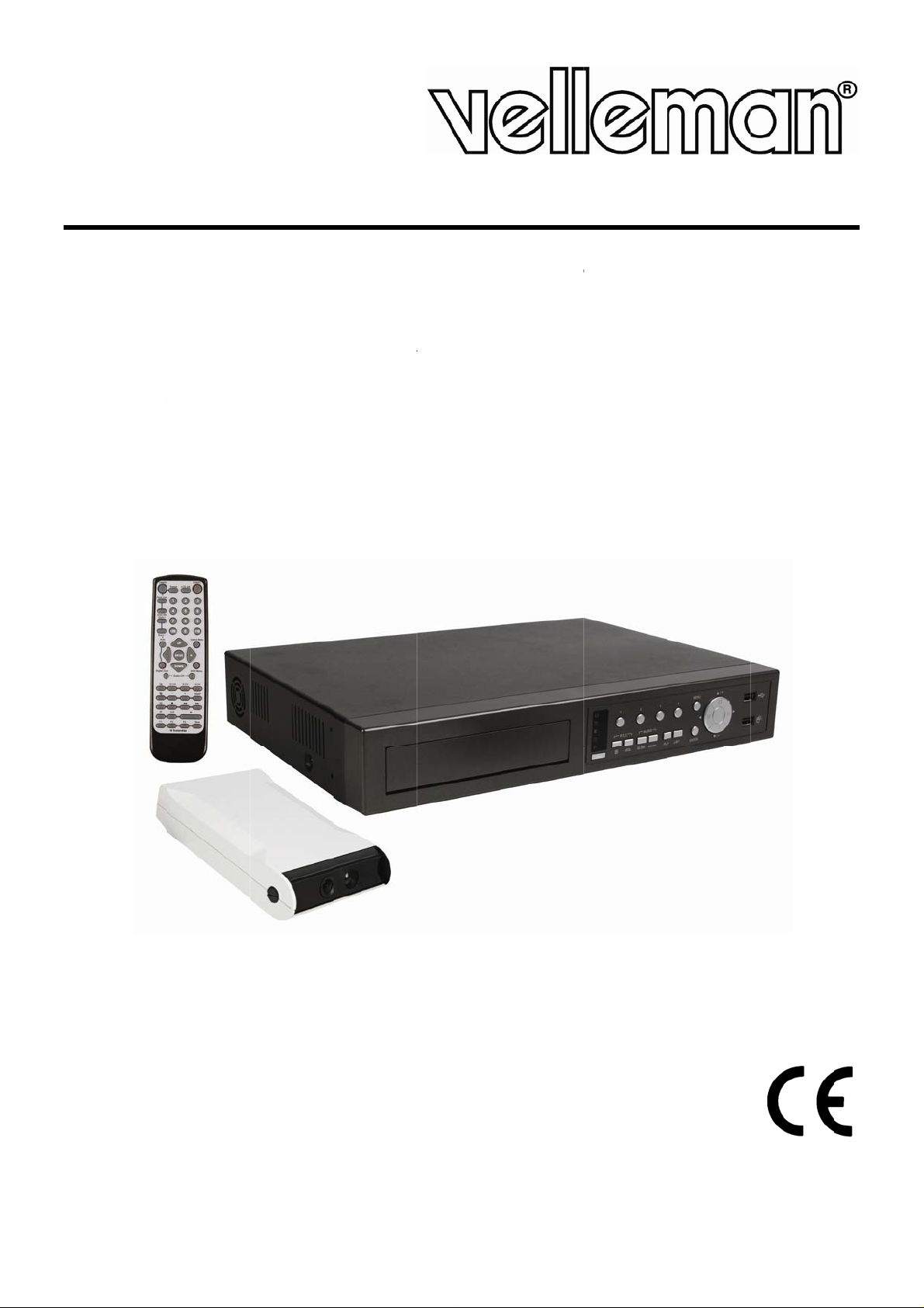
A
B (SATA)
power supply data bus
voeding databus
alimentation bus de données
alimentación bus de datos
Stromversorgung Datenbus
1 DC 12V input terminal
2 Video output connector
1 DC 12V ingangsaansluiting
2 Video-uitgangsaansluiting
1 Connexion d’entrée CC 12V
2 Connexion de sortie vidéo
1 DC 12V-Eingangsanschluss
2 Video-Ausgangsanschluss
1 Conexión de entrada CC 12V
2 Conexión de salida de vídeo
* not incl. - niet meegelev. - non incl. - no incl. - *nicht mitgeliefert
V. 02 – 02/05/2012 3 ©Velleman nv
Page 4
.
oIm
n
Smocom
scou
a
.
A
.
o
n
n
m
e
a
w
w
t
r
t
m
n
euse
p
p
e
s
c
O
epar
wear
e
e
e
h
s
e
d
e
E
t
h
n
t
a
n
e
e
o
s
c
s
a
f
u
y
o
e
o
s
l
y
h
A
t
d
S
C
e
m
K
n
t
r
c
s
r
t
p
v
d
a
o
u
r
n
t
h
m
e
e
p
d
o
u
p
e
d
c
a
n
T
t
o
.
e
e
R
h
c
A
o
i
e
d
m
“
t
e
a
n
e
e
d
y
p
u
W
m
v
2
T
t
c
t
o
e
d
u
c
d
e
u
O
R
a
e
e
v
l
o
e
h
a
d
o
n
t
b
G
v
r
e
T
h
d
o
p
o
r
i
c
d
r
i
g
p
d
b
u
n
n
o
e
w
a
n
o
b
i
d
t
a
n
d
b
p
g
w
t
o
c
t
e
d
t
f
t
s
e
e
e
/
t
p
t
u
o
n
l
O
t
e
a
o
n
IVSPROM
1
Intr
T
all reside
portant e
Th
ank you for
bri
nging this d
(E
glish only).
IV
DVR Syst
bile device
es with m
Se
e http://w
vi
it the IVS
and
ntries.
registered
All
cl
rification of
Fo
r licensing,
This
symbol on t
har
the enviro
shou
ld be taken
distri
butor or to
If in
doubt, co
choosing V
evice into s
(iPhone, iPa
w.youtube.
ebsite.
rademarks
the compat
efer to the
duction
ts of the
vironmen
m is the W
ny mobile
(EagleEye
QUIC
uropean U
al informa
e device o
ment. Do n
o a speciali
local recy
tact your l
lleman! It i
rvice the fi
rld’s 1st In
d, Android
urveillance
om/watch?
) - The tra
nd trade n
ibility of our
ull user ma
INS
ion
ion about
the packag
ot dispose
zed compan
ling service
ocal waste
strongly r
st time. Th
elligent DV
hone…) wit
functions in
=DKKzWJ
emark appl
mes are pr
products w
nual on the
ALLA
his produ
e indicates
f the unit (
y for recycli
Respect th
disposal a
commende
complete
Surveillan
EagleEyes
luding reco
g7Lw for a
ication is fil
perties of t
th the prod
included CD
ION
t
hat disposa
r batteries)
ng. This de
local envi
uthorities.
to read th
ser manual
e System.
software w
gnizing and
emo video
d and unde
heir respect
cts of the
-ROM.
UIDE
l of the devi
as unsorte
ice should
onmental r
full versio
can be fou
his system
en events
counting p
or http://w
r process in
ive owners
ifferent ma
ce after its l
municipal
e returned
les.
manual th
d on the in
instantaneo
ccur. Easy
ople.
w.eagleey
the U.S. an
nd are use
ufacturers.
ifecycle cou
aste; it
o your
roughly bef
luded CD-R
usly notifies
o install. It
scctv.com/
d other
only for th
d
ore
M
a
o
2
Safe
C
UTION:
To
reduce the
ap
paratus fro
da
mages arisi
Th
be
Thi
im
ap
Ke
Ri
ele
D
us
Thi
po
lik
y Instr
risk of elect
the type o
g out of an
lightning fl
r to the pre
of sufficient
s exclamati
ortant oper
liance.
p the devic
k of electr
troshocks.
NOT disas
r-serviceab
ts.
s is a Safet
er cord). T
th contact.
ly to make
ctions
ric shock, d
f power sou
improper
ash with ar
sence of no
magnitude
n mark wit
ating and m
away fro
shock wh
Have the d
emble or o
e parts insi
Class 1 Pr
e mains pl
ny interru
he instrum
RISK
not expos
rce indicate
se, even if
owhead sy
-insulated
o constitut
in an equil
aintenance
children a
n opening t
vice repaire
en the cov
e the devic
duct (provi
g shall onl
tion of the
nt dangero
CAUTI
OF ELECT
this appar
on the lab
we have be
bol, within
dangerous
a risk of el
teral triang
(servicing) i
d unauthori
he cover. T
d by qualifi
r unless ot
. Refer to
ed with a p
be inserte
rotective c
s. Intentio
N
IC SHOCK
tus to rain
l. The com
n advised
an equilate
oltages” wi
ectric shock
e is intende
nstructions
sed users.
uching live
d personnel
erwise indi
n authorize
rotective ea
in a socket
nductor ins
al interrupt
r moisture.
any shall n
f the possi
al triangle,
thin the pro
to persons.
d to alert th
n the litera
wires can c
.
ated in this
dealer for
thing grou
outlet provi
de or outsi
ion is prohi
Only opera
t be liable
ility of such
s intended
uct’s enclo
e user to th
ure accomp
use life-thr
manual. Th
service and
d incorpora
ded with a
e of the ins
ited.
e this
or any
damages.
o alert the
ure that m
presence
anying the
atening
re are no
or spare
ed in the
rotective
rument is
y
f
3
Gen
Re
fer to the V
be
found on t
•
Indoor u
objects fill
•
Keep this
around th
•
Protect thi
V.
02 – 02/05/2
ral Gui
lleman®
e included
e only. Ke
d with liqui
evice away
apparatus.
s device fro
012
elines
ervice an
D ROM.
p this devi
d on top.
from dust
shocks a
Quality
e away for
nd extreme
d abuse. A
arranty on
rain, mois
heat. To o
oid brute fo
4
the last pa
ure, splashi
tain sufficie
rce when o
es of the fu
ng and drip
nt air coolin
erating the
ll user man
ing liquids.
, leave en
device.
al which ca
Never put
ugh space
©Vellema
nv
Page 5
IVSPROM2
• Familiarise yourself with the functions of the device before actually using it.
• All modifications of the device are forbidden for safety reasons. Damage caused by user modifications to
the device is not covered by the warranty.
• Only use the device for its intended purpose. Using the device in an unauthorised way will void the
warranty.
• Damage caused by disregard of certain guidelines in this manual is not covered by the warranty and the
dealer will not accept responsibility for any ensuing defects or problems.
• Keep this manual for future reference.
• DO NOT use this product to violate privacy laws or perform other illegal activities.
4. Features
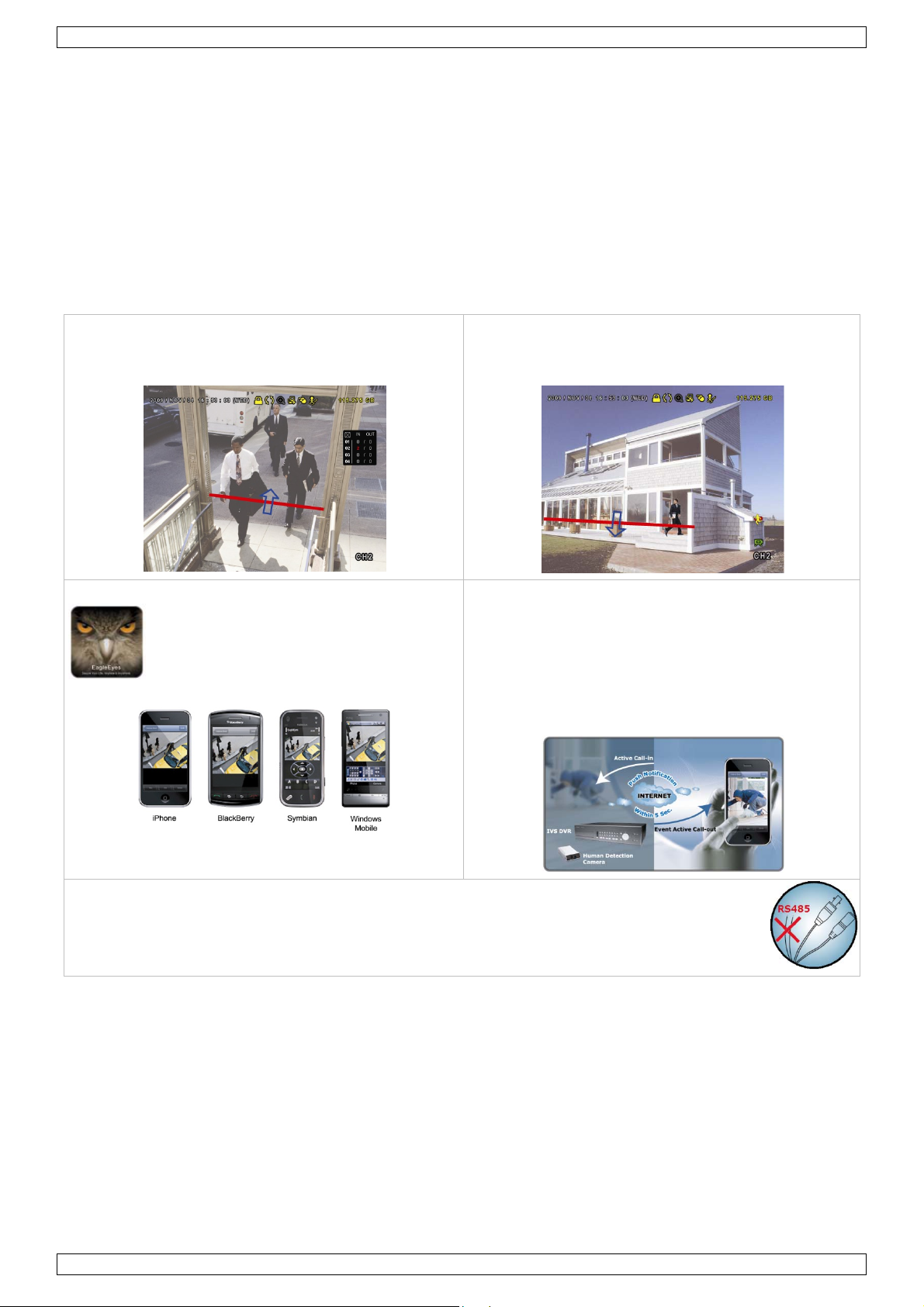
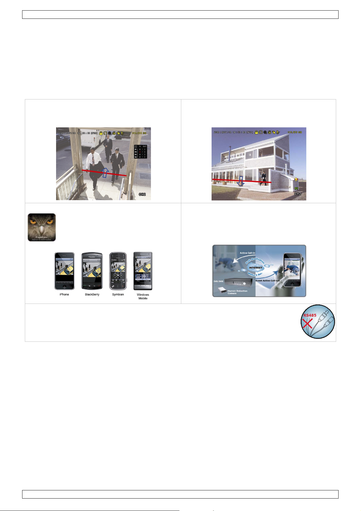
The IVS DVR holds following features:
Flow counting
A virtual detection line can be set to detect the moving
direction of pedestrians for flow counting
Virtual fence / one-way pass
A virtual intruder detection line is set to detect
intruders coming from a specified direction
Power Mobile support
Eagle Eyes for Mobile Surveillance.
Mobile surveillance via the EagleEyes
software is supported on many popular
mobile platforms, e.g. iPhone, Android,
BlackBerry, Windows Mobile and Symbian.
DVR/Camera Communication System (DCCS) technology
With this system, control signals can be transferred directly via coaxial cable to control the
human detection camera. This highly simplifies the installation and reduces labour cost and
working hours.
IVS Human Detection camera
• Built-in Infrared sensor alarm for human detection and sending push notifications to a mobile device
(iPhone, iPad, Android phone…)
• Supports DVR / Camera Communication System (DCCS) Technology
o There is no need to additionally connect RS485 control wires for camera control because the control
signals can be transferred directly via coaxial cables.
o Camera installation is highly simplified resulting in lower labour cost and working hours.
• IR LEDs built-in for 24-hour day & night surveillance
• Smart Light Control to dynamically adjust image performance for clear and accurate images.
Push notification on mobile device
When an event is detected by the human detection
camera, the IVS DVR will immediately send an instant
notification (Push notification) to a mobile device
(iPhone, iPad, Android phone…) within 5 seconds. Once
the notification is confirmed the mobile surveillance
software (EagleEyes) is automatically activated for
remote access.
V. 02 – 02/05/2012 5 ©Velleman nv
Page 6

IVSPROM2
System
• GUI (Graphical User Interface) display and USB mouse control
• Gmail integration supports notification through Google mail server and any other mail support
• local and remote control completely independent
• VGA interface built-in with output resolution up to 1600 x 1200
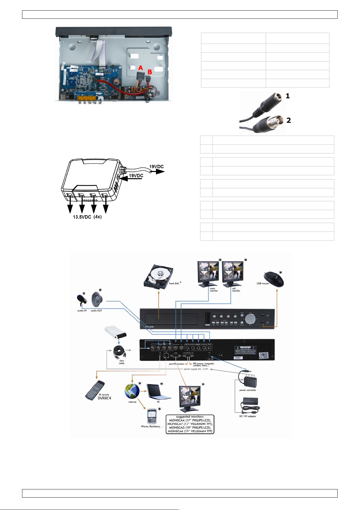
• set contains:
o 1 x 4-channel H.264 Full frame DVR
o 1 x human detection PIR camera
o 1 x IR remote control
o 1 x 20m camera cables
o 1 x 19V PSU
o 1 x high-efficiency DC-DC converter for DVR and 4 cameras
• hard disks in option: (not included) 500GB (HD500GB/S) or 1TB (HD1TB/S)
• IR remote control: DVRRC4 (incl.)
• optional monitor (not incl.): MONSCA4, MONSCA5, MONSCA6, MONSCA7
• optional router (not incl.): PCRT1, EM4542, EM4553, EM4570.
5. Connection and setup
Before the DVR is powered on, make sure you have installed a hard disk, connected at least one camera and a
monitor.
Note: The DVR is designed to automatically detect the video system of the connected cameras (NTSC or PAL).
To make sure the system detection is correct; please check if the cameras are connected to the DVR and
power-supplied before the DVR is powered on.
5.1 Prerequisites
• To ensure the signal transmission, the recommended distance between this DVR and cameras should not
exceed 200 meters by using 3C2V coaxial cables (112 braids).
Using different types of coaxial cables or longer connection distances may influence the availability and
continuity of signal transmission.
• Do not use a signal booster or modem to amplify signals and extend the connection distance.
5.2 Hardware setup
Refer to the illustrations on page 3 of this quick installation guide.
Connecting a video monitor
Obtain a suitable monitor (not included) and connect it to the BNC or VGA video output port on the back of
the DVR.
Note: the CAL video output simply shows the camera output(s) directly from the video input ports. Data and/or
actions performed via the main monitor are not shown.
Connecting the power supply
1. Plug the DC output connector of the included power adaptor into the 19VDC power input at the back of
the DVR.
WARNING: only use the included adaptor.
2. Plug the included power cable into the adaptor input connector and plug the other end into the mains.
Do not switch the DVR on yet.
Connecting a camera
1. Choose a location for the camera, keeping following guidelines in mind:
o Do not install the camera in locations where extremely high or low temperatures or excessive vibrations
may occur.
o Avoid mounting the camera near high electro-magnetic fields.
o Do not aim the camera at the sun or other extremely bright objects.
2. Use the included cables to connect the video output of the camera to either video input at the back of
the DVR. The number next to the input connectors represents the channel number. Connector type is BNC.
3. Connect each camera to the power supply adaptor.
Note: The cameras must be connected and powered on before the DVR is powered on.
V. 02 – 02/05/2012 6 ©Velleman nv
Page 7

IVSPROM2
Connecting audio
• The DVR supports four audio inputs. Connect the audio output of an audio source to an audio input of
the DVR. Make sure to connect the audio channel to the corresponding video channel. Connector type
is RCA.
• There is also an audio output connector. Connect an audio device e.g. a speaker to this connector when
desired. Connector type is RCA.
Note: the cameras shipped with the IVSPROM2 DO NOT support audio recording.
Connecting Local Area Network (LAN)
Connect the DVR to a local network by plugging a network cable into the LAN port at the back of the DVR.
Connector type is 8P8C (RJ45). Setup is done through the OSD.
5.3 DVR power on
1. This device should be operated only with the type of power source indicated on the manufacturer’s label.
Connect the indicated AC power cord to the power adapter, and plug into an electrical outlet.
Note: Before the DVR is powered on, make sure that (1) the cameras are connected and powered on for
the detection of the camera video system to be correct, and (2) a monitor (either LCD or CRT monitor, not
incl.) is connected to the DVR for correct video output detection.
2. Switch on the DVR with the power switch on the back of the device. It will take about 30s for the DVR to
initialize.
Note: To ensure that your DVR works constantly and properly, it is recommended to use an UPS
(Uninterruptible Power Supply, not incl.), for continuous operation.
5.4 Date and time setting
Before operating your DVR, please set the date and time on your DVR FIRST.
Note: DO NOT change the date or time of your DVR after the recording function is activated. Otherwise, the
recorded data will be disordered and you will not be able to find the recorded file from backup by time search.
If users change the date or time accidentally when the recording function is activated, it is recommended to
clear all HDD data, and start recording again.
Note: when using the DVR for the first time, leave it powered on for at least 48 hours continuously after the
date & time is set correctly. To replace the internal battery, refer to APPENDIX 6 in the full user manual.
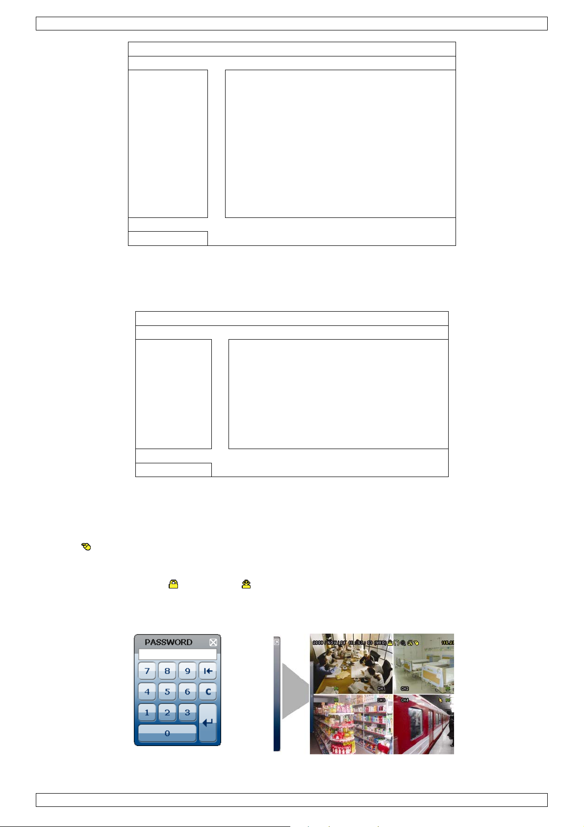
1. Right-click to enter the DVR password with the password keypad. The default administrator password
is 0000.
The status will be changed from (key lock) to (administrator).
2. Right-click to show the main menu, and select QUICK START > TIME SETUP to set the date & time.
QUICK START
GENERAL DATE 2009 / NOV / 17
TIME SETUP TIME 15 : 35 : 53
EXIT
5.5 Clear hard disk
It is recommended to clear all data in the hard disk when using this DVR for the first time to ensure the
recorded data are not mixed with other data previously saved in the same hard disk.
1. Right-click to show the main menu, and select SYSTEM > SYSTEM INFO > CLEAR HDD.
2. The DVR will reboot when HDD data are cleared. For details, refer to §5.3.2 in the full user manual.
V. 02 – 02/05/2012 7 ©Velleman nv
Page 8
IVSPROM2
SYSTEM
TOOLS BAUD RATE 2400
SYSTEM INFO HOST ID 000
USB BACKUP R.E.T.R 5
DVD BACKUP AUTO KEY LOCK NEVER
CLEAR HDD HDD-0
RESET DEFAULT SUBMIT
REMOTE CONTROL ID 000
SERIAL TYPE RS485
VIDEO FORMAT NTSC
VERSION 1019-1008-
1010-1010
EXIT
5.6 Password setting
1. Right-click to show the main menu, and select SYSTEM > TOOLS to change the DVR password.
2. There are two user levels: ADMIN and OPERATOR. For details, please refer to 5.3.1 TOOLS in the full user
manual.
SYSTEM
TOOLS LANGUAGE ENGLISH
SYSTEM INFO ADMIN PASSWORD SETUP
USB BACKUP OPERATOR PASSWORD SETUP
DVD BACKUP UPGRADE SUBMIT
BACKUP CONFIG SUBMIT
RESTORE CONFIG SUBMIT
EXIT
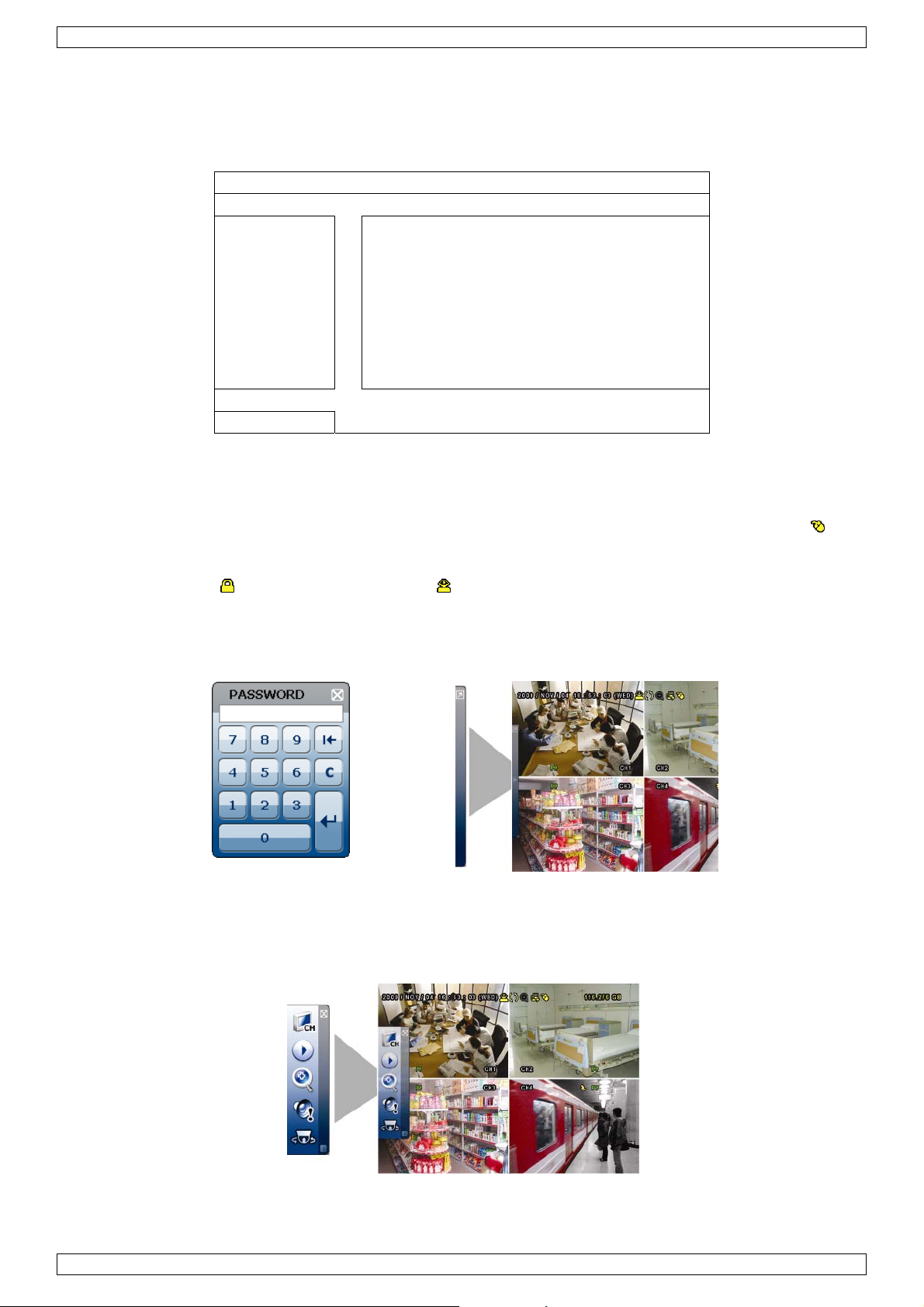
6. GUI display with USB mouse control
6.1 Connect a USB mouse
1. Connect a USB mouse (not incl.) to the mouse port on the DVR front panel, and check if there is a mouse
icon on the screen, in dicating the USB mouse is detected properly.
2. Move your mouse to enter the DVR password with the password keypad. The default administrator
password is 0000.
The status will change from (key lock) to (administrator), and the quick menu bar appears on the left side
of the screen.
Note: There are two user levels for DVR access which can be set in the main menu SYSTEM > TOOLS.
Password Input Quick Menu (closed)
V. 02 – 02/05/2012 8 ©Velleman nv
Page 9
IVSPROM2
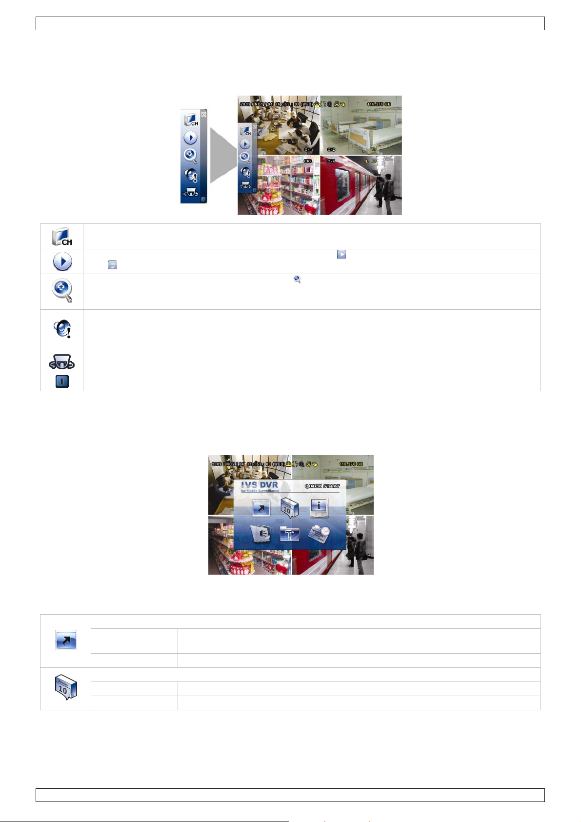
6.2 Quick menu bar
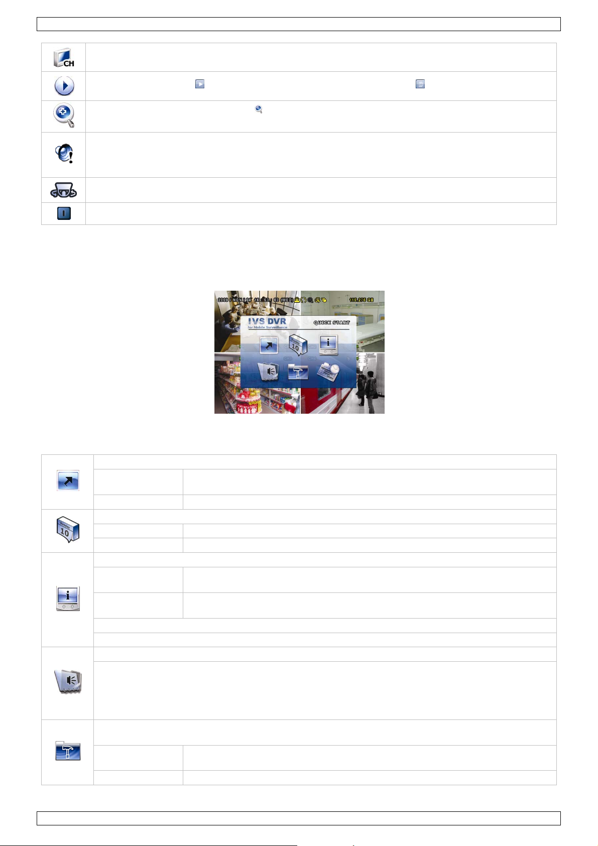
Move to the mouse pointer to the left of the screen to extend the quick menu bar and show the six functions:
Quick Menu (extended)
Click to show the channel switch panel and select the preferred panel layout.
Click to display the playback the control panel, and click to play the latest recorded video clip, or
click to enter the search list.
Switch to the channel you want first, and click to enter the zoom-in mode. In this mode, click and
drag the red frame on the bottom left of the screen to move to the place you want to see. To exit this
mode, click 7.
Click to select the desired audio channel.
In live mode, only the live audio channels can be selected.
In playback mode, live and playback audio channels can be selected.
Click to enter the PTZ mode and show the PTZ camera control panel (when applicable).
Click to show the power off panel to either halt or reboot the system.
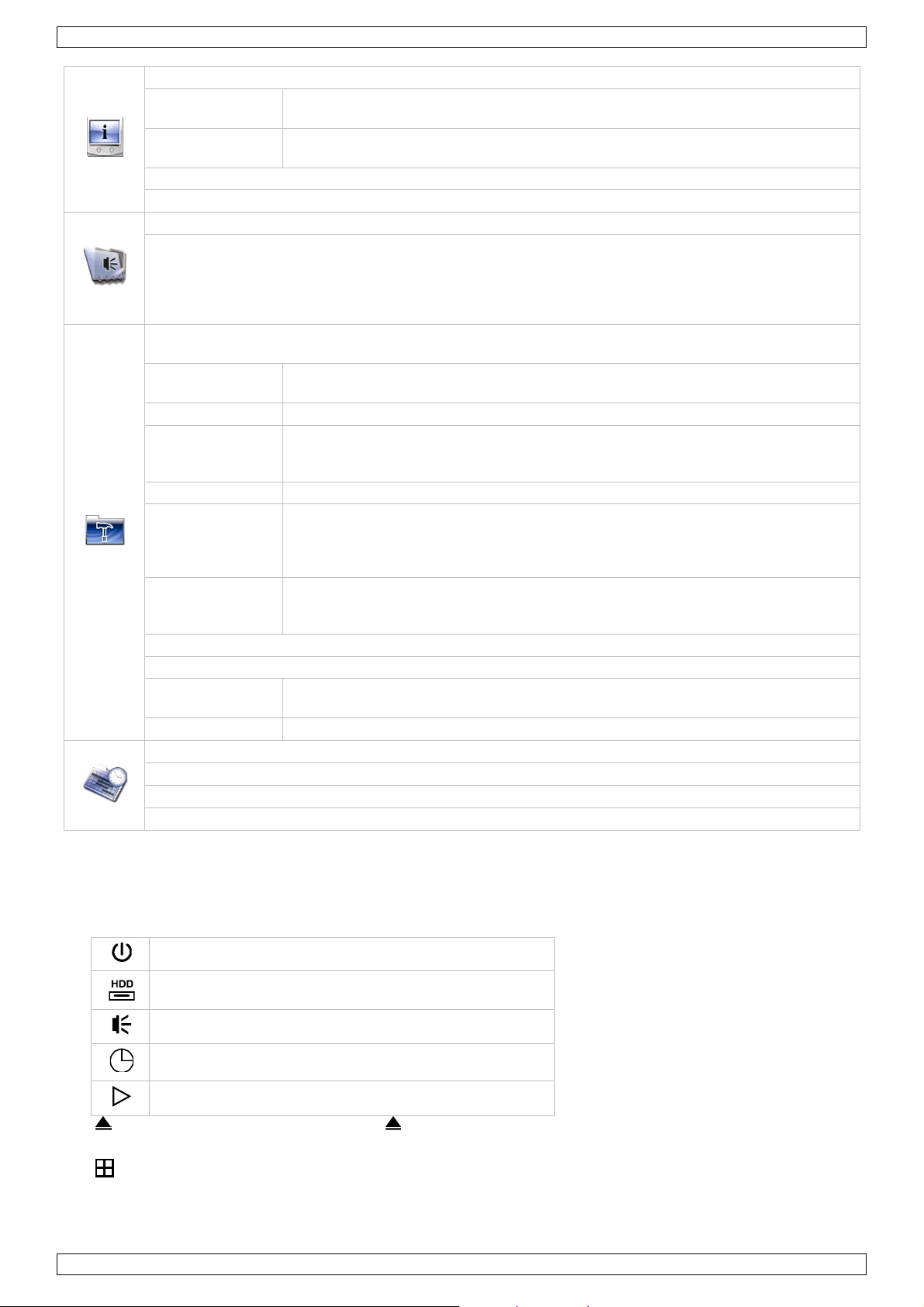
6.3 Main menu
Right-click anywhere on the screen to show the main menu as follows, and right-click again to exit.
Main Menu
Main menu structure
*: selected models only
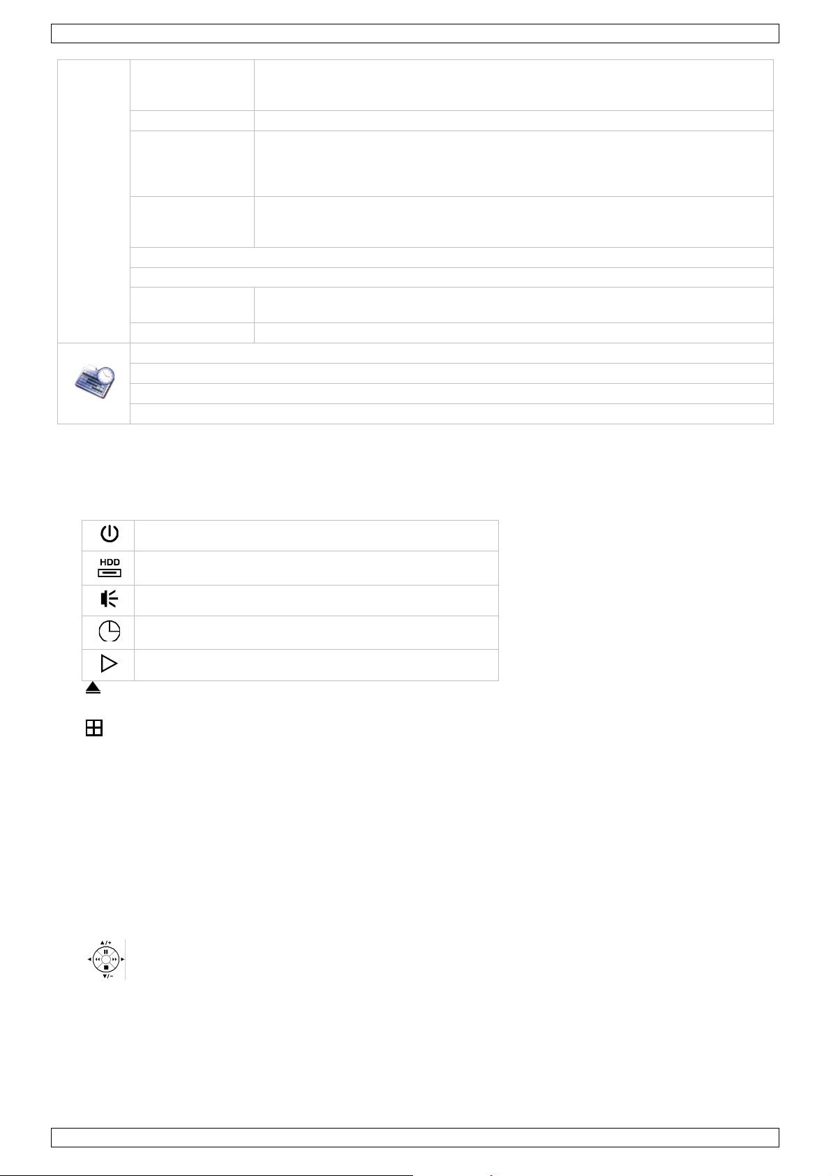
QUICK START: click to set the status display, image settings, and date & time.
GENERAL
TIME SETUP DATE - TIME
DATE SETUP: click to set the date display and daylight saving.
DATE INFO DISPLAY DATE OF MODE – FORMAT
DAYLIGHT DAYLIGHT SAVING
CHANNEL TITLE – EVENT STATUS – DATE DISPLAY – DCCS DISPLAY – MOUSE
SENSITIVITY – PRIORITY* – RECORD CONFIG
V. 02 – 02/05/2012 9 ©Velleman nv
Page 10
IVSPROM2
SYSTEM: click to set the system configurations.
TOOLS
SYSTEM INFO
BACKUP DATA (USB)
BACKUP LOG (USB)
EVENT INFORMATION: click to enter the event search menu.
QUICK SEARCH
EVENT SEARCH
HDD INFO
EVENT LOG
ADVANCED CONFIG: click to set CAMERA, DETECTION, ALERT, NETWORK, DISPLAY, RECORD,
DEVICES, DCCS, IVS* & NOTIFY*.
CAMERA
DETECTION LS – SS – TS – MOTION – ALARM - AREA
ALERT
NETWORK NETWORK – SNTP – FTP – E-MAIL
DISPLAY
RECORD
DEVICES
DCCS
IVS*
NOTIFY* GUARD
SCHEDULE SETTING: click to set record timer and detection timer.
RECORD
DETECTION
ALARM
LANGUAGE – ADMIN PASSWORD – OPERATOR PASSWORD – UPGRADE BACKUP CONFIG – RESTORE CONFIG
BAUD RATE – HOST ID – R.E.T.R. – AUTO KEY LOCK – CLEAR HDD – RESET
DEFAULT – REMOTE CONTROL ID – SERIAL TYPE – VIDEO FORMAT – VERSION
BRIGHTNESS – CONTRAST – SATURATION – HUE - COV. – REC - CHANNEL
TITLE
EXT. ALERT – INT. BUZZER – KEY BUZZER – VLOSS BUZZER – MOTION BUZZER
– ALARM BUZZER – HDD BUZZER – ALARM DURATION (SEC) – HDD NEARLY
FULL (GB)
DE-INTERLACE* – FULL SCREEN DURATION – QUAD SCREEN DURATION* –
CALL SCREEN DURATION – DISPLAY COVERT – HDD DISPLAY MODE – VIDEO
OUTPUT* – ALPHA BLENDING – VGA OUTPUT – VGA DEINTERLACE* –
COMPOSITE DEINTERLACE*
MANUAL RECORD – EVENT RECORD – TIMER RECORD – PRE-ALARM RECORD –
OVERWRITE – EVENT RECORD ALL CH – KEEP DATA LIMIT (DAYS) – RECORD
CONFIG
CAMERA* – IVS MODE – DISPLAY LINE – SENSITIVITY – RESET COUNT –
VIRTUAL FENCE AREA – SCENE CHANGE – SCENE CHANGE SENSITIVITY
7. Front and rear panels
7.1 Front Panel
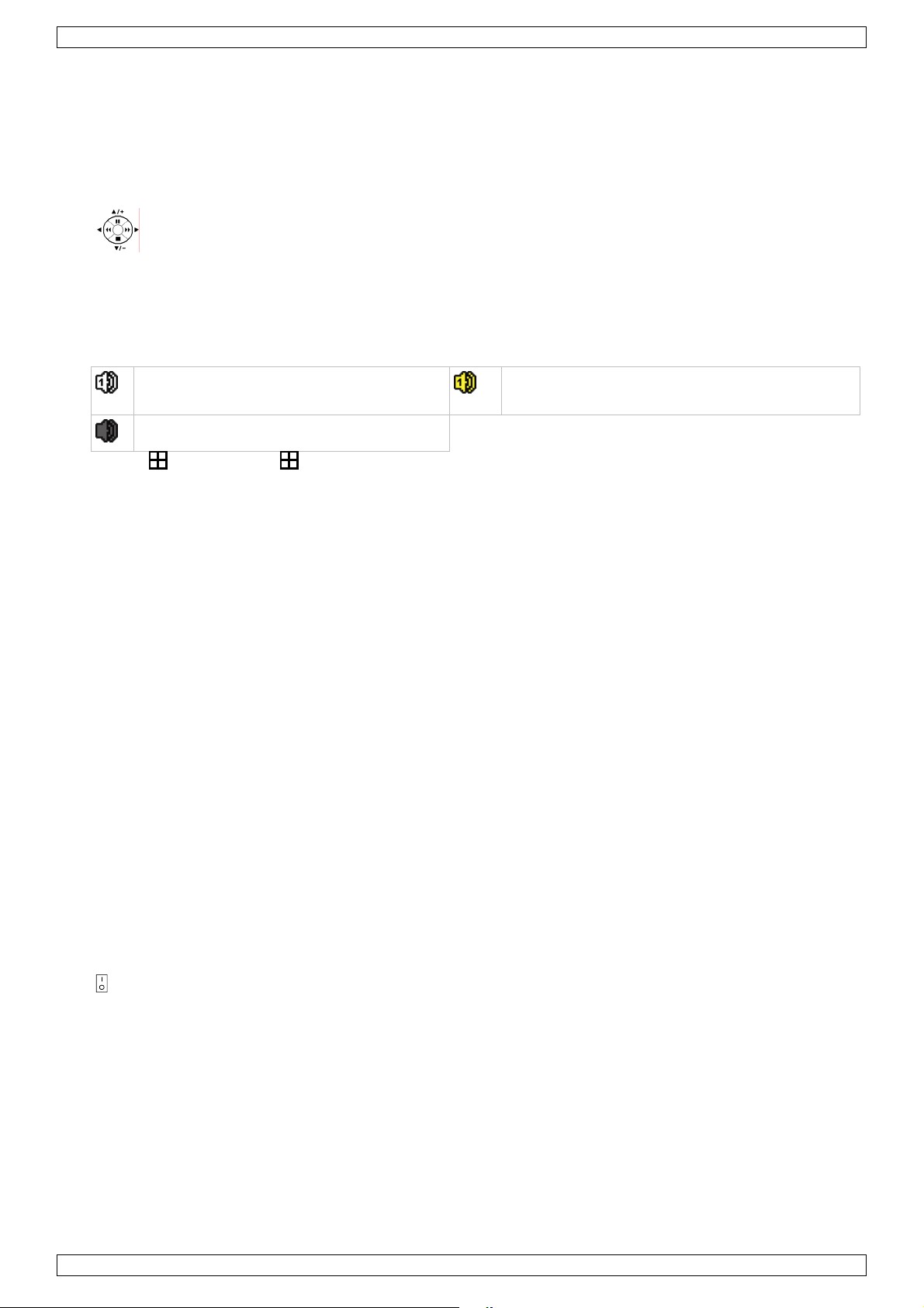
• LED indicators
DVR is powered on.
HDD is reading or recording.
An alarm is triggered.
Timer recording is on.
Under playback status.
• : For models with a DVD writer, press to open or close it.
• CH1 ~ 4: Press the channel number buttons to select the channel to display.
• : Press to show the 4 channel display mode.
• SEQ: Press to display each channel in full screen one by one starting from CH1. When the last channel is
displayed, it will repeat from CH1 again. To exit this mode, press SEQ again.
• SLOW: In playback mode, press to show slow playback.
V. 02 – 02/05/2012 10 ©Velleman nv
Page 11
IVSPROM2
• ZOOM: Press to enlarge the picture of the selected channel (in FRAME or FIELD recording mode).
• PLAY: Press to playback the latest recorded data.
• LIST (Event List Search): Press to quickly search the recorded files by event lists: RECORD / MOTION /
ALARM / TIME / HUMAN DETECTION / IVS / STATISTIC, or select FULL to show all the event logs.
To quickly search the time you want, select QUICK SEARCH. For more details, refer to the full user manual.
• MENU: Press MENU to enter the main menu.
• ENTER: Press ENTER to confirm the setting.
• : Press ▲ / ▼ / ◄ / ► to move up / down / left / right.
In playback mode:
Press to pause playback.
Press to stop playback.
Press to fast forward.
Press to fast rewind.
• AUDIO (SLOW + ZOOM): Press SLOW + ZOOM to select live or playback audio from audio channel 1~4.
Live audio from audio channel 1~4
(indicated in white).
Audio channel unselected
• P.T.Z. ( + SEQ): Press + SEQ at the same time to enter or exit the PTZ control mode.
• USB port: There are two USB ports on the front panel, one for connecting a USB mouse for mouse control,
and the other one for connecting an USB flash drive for video backup.
Note: Do not connect two USB mice or two USB flash drives simultaneously.
Note: For compatible USB flash drive list, please refer to APPENDIX 3 in the full user manual.
Playback audio from audio channel 1~4 (indicated
in yellow).
7.2 Rear Panel
• VIDEO IN (1 ~ 4): Connect to the video connector of a camera.
Note: The DVR will automatically detect the video system of the camera; make sure that the cameras are
properly connected to the DVR and powered before the DVR is turned on.
• AUDIO IN (1~4): Connect to the audio connector of a camera if the camera supports audio recording.
Note: To make a video backup with audio, make sure the camera which supports the audio function is
connected to the video-in channel and audio-in channel. For example, the audio data from audio CH1 will
be recorded with the video data from video CH1.
• AUDIO OUT: Mono audio output to connect to a speaker.
• MONITOR: Connect to a CRT monitor for video output.
Note: While connecting to a CRT monitor, it is also supported to connect to an LCD monitor simultaneously
for dual video output.
• CALL: Connect to a monitor specific for sequence display.
• VGA: Connect to an LCD monitor directly.
Note: While connecting to an LCD monitor, it is also supported to connect to a CRT monitor simultaneously
for dual video output.
• IR: Connect an IR receiver extension line (not incl.) for remote control.
• EXTERNAL I/O: This port is used to connect external devices (such as speed dome cameras or external
alarm, etc).
• LAN: Connect to Internet by LAN cable.
• DC 19V: Connect to the supplied adapter.
• Power Switch: Switch to | to turn on the power, to | to turn off the power.
V. 02 – 02/05/2012 11 ©Velleman nv
Page 12
IVSPROM2
8. Basic operation
Note: some of the features and functions described below only apply to the human detection camera.
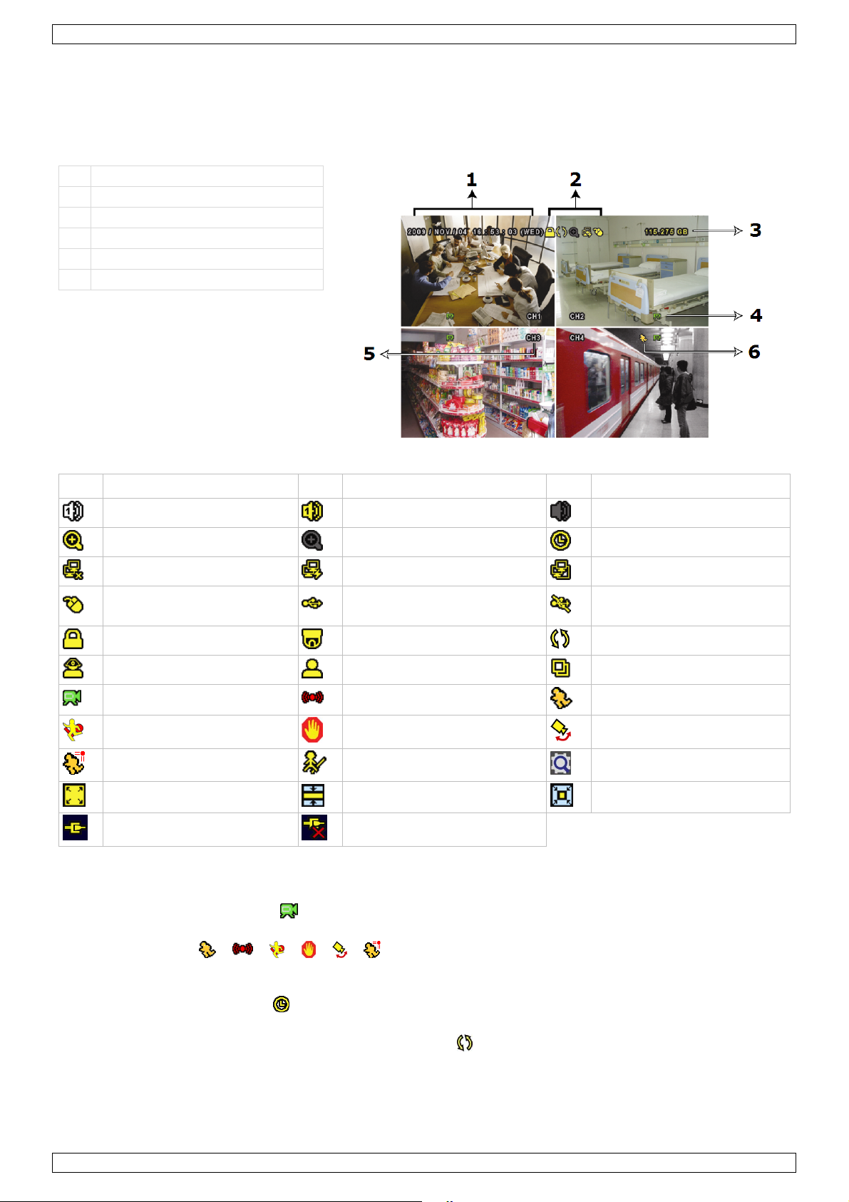
8.1 Live page
Refer to the image below.
1 system time
2 status bar
3 available disk capacity
4 recording icon
5 channel
6 motion icon
Icon Function Icon Function Icon Function
Live audio channel (1~4)
Digital zoom on
Network disconnected
USB mouse connected
Key lock
Administrator
Recording
Virtual fence event
Human detection event
Record mode: Frame
DCCS connection OK
Playback audio channel (1~4)
Digital zoom off
Internet connected
USB flash drive / device
connected
PTZ mode on
Operator
Alarm event
One way pass event
Flow counting enabled
Record mode: Field
DCCS connection failed
Audio channel off
Timer recording
LAN connected
No USB device connected
HDD overwrite
Sequence
Motion event
Scene Change event
Smart zoom
Record mode: CIF
8.2 Record icon
• Manual Recording
By default, manual recording is on when the DVR is powered on and a HDD is installed.
• Event Recording
The event icons, / / / / / , are shown on the display when their respective events
occurred and the related record function is on.
• Timer Recording
When timer recording is on, is displayed on the screen.
• HDD Overwrite
Be default, the HDD overwrite function is set to ON, and will be shown on the screen.
V. 02 – 02/05/2012 12 ©Velleman nv
Page 13
IVSPROM2
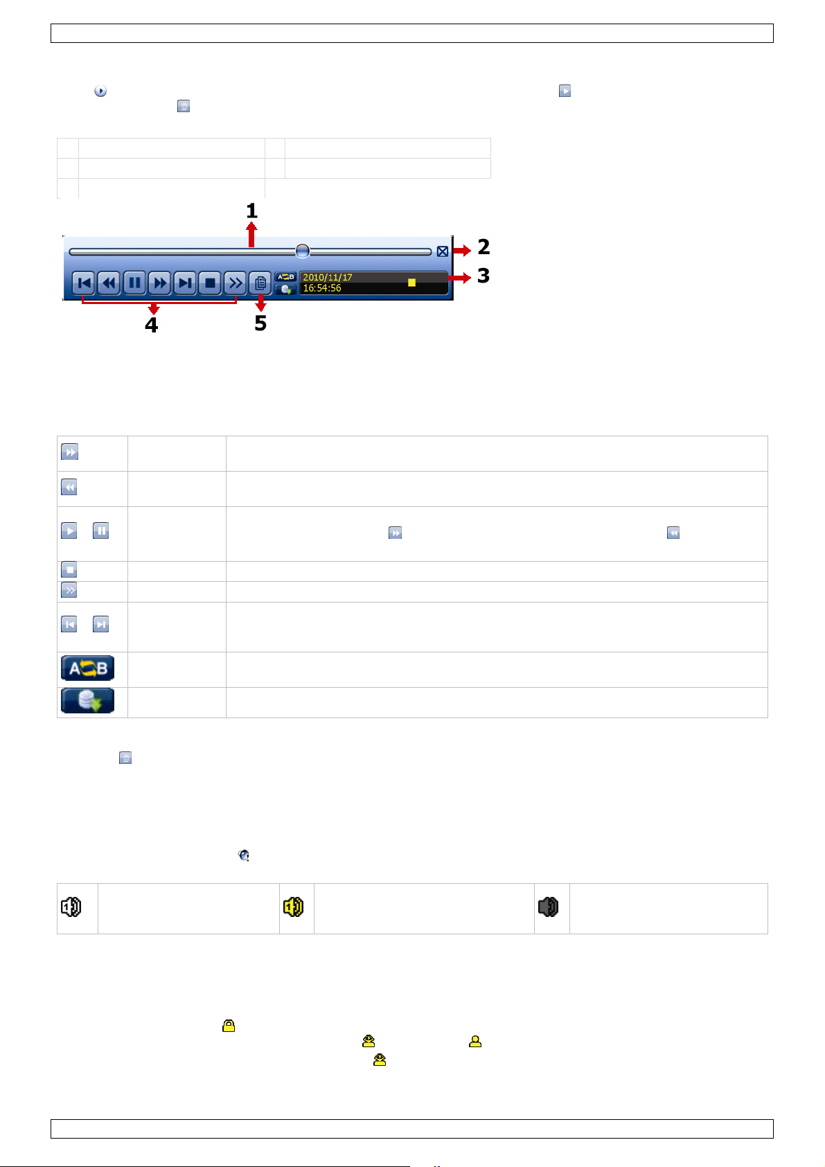
8.3 Playback
Click on the quick menu bar to display the playback control panel, and click to play the latest recorded
video clip, or click to enter the search list.
Refer to the image below:
1 progress bar 4 control bar
2 close 5 event search
3 information bar
Note: There must be at least 8192 images of recorded data for playback to work properly. If not, the device
will stop playback. For example, if the IPS is set to 30, the recording time should be at least 273 seconds
(8192 images / 30 IPS) for the playback to work properly.
Note: During playback, the image size of the recording (FRAME, FIELD or CIF) will be shown on the screen.
Playback control
/
/
Fast Forward
Fast Rewind
Play / Pause
Stop Click to stop the video playback.
Slow Playback Cli c k once to get 1/4X speed playback, and click twice to get 1/8X speed playback.
Previous /
Next Hour
Repeat
Increase the speed for fast forward. Click once to get 4X speed forward, click twice
to get 8X speed, etc. Maximum speed is 32X.
Increase the speed for fast rewind. Click once to get 4X speed rewind, click twice to
get 8X speed, etc. Maximum speed is 32X.
Click to play the latest recorded video clip immediately, click again to pause.
In the pause mode, click once to get one frame forward, and click to get one
frame rewind.
Click to jump to the next / previous time interval in an hour, for example,
11:00 ~ 12:00 or 14:00 ~ 15:00, and start playing the earliest event video clip
recorded during this whole hour.
Click to set point A and point B in a video clip, and the system will play only the
specified range in that clip.
Backup Click to open the backup menu for video backup.
Event search
• Click to quickly search the recorded files by event lists: RECORD / MOTION / ALARM / TIME / HUMAN
DETECTION / IVS / STATISTIC, or select FULL to show all the event logs.
• To quickly search the time you want, select QUICK SEARCH. For more details, refer to §5.4.1 in the full
user manual.
Audio playback
In the playback mode, click on the quick menu bar as many times as needed to select live or playback audio
from audio channel 1~4.
Live audio from audio
channel 1~4 (indicated in
white).
Note: To make a video backup with audio, make sure the camera which supports the audio function is
connected to the video-in channel and audio-in channel. For example, the audio data from audio CH1 will be
recorded with the video data from video CH1.
Playback audio from audio
channel 1~4 (indicated in yellow).
Audio channel unselected
8.4 User switch
• In the key lock mode , move your USB mouse to display the password input keypad. There are two user
levels for accessing the DVR: Administrator and Operator .
• When the administrator password is entered, will be shown on the status bar of the screen and all
operations are allowed. The default administrator password is 0000.
V. 02 – 02/05/2012 13 ©Velleman nv
Page 14

IVSPROM2
• When the operator password is entered, will be shown on the status bar of the screen, and the main
menu is NOT accessible. The operator user level needs to be set in the main menu SYSTEM > TOOLS.
• To switch between these two user levels, click the current user level icon to switch to the key lock mode,
and move your mouse to show the password input keypad, and enter the password of the user level you
want.
8.5 Video output switch
Showing the video output simultaneously on a CRT monitor (connected to MONITOR) and LCD monitor
(connected to VGA) is supported.
To set the video output:
1. When the DVR is powered on and initialized, right-click to show the main menu, and select
ADVANCED CONFIG > DISPLAY > VIDEO OUTPUT.
2. Select BOTH if you want to output images on both LCD and CRT monitors; select VGA if you want to
output images on an LCD monitor; select COMPOSITE if you want to output images on a CRT monitor.
ADVANCED CONFIG
CAMERA DE-INTERLACE (For Selected Models Only) OFF
DETECTION FULL SCREEN DURATION 03
ALERT QUAD SCREEN DURATION (For Selected Models Only) 03
NETWORK CALL SCREEN DURATION 03
DISPLAY DISPLAY COVERT ON
RECORD HDD DISPLAY MODE HDD SIZE
DEVICES VIDEO OUTPUT (For Selected Models Only) BOTH
DCCS ALPHA BLENDING 200
IVS VGA OUTPUT 1024 X 768
NOTIFY VGA DEINTERLACE (For Selected Models Only) ON
COMPOSITE DEINTERLACE(For Selected Models Only) ON
EDIT
9. Set push notification
Note: only available on the human detection camera.
This IVS DVR series supports instant event notifications to your mobile device (iPhone, iPad, Androi d…) with our
self-developed program, EagleEyes, installed. When a human is detected by a human detection camera, the
DVR will immediately receive alarm signals and send them to your mobile device.
Note: EagleEyes is a powerful mobile surveillance program developed by AV TECH Corporation. For more
operations details about EagleEyes, visit http://www.eagleeyescctv.com.
For any comment or question about this program, contact Velleman. Visit www.velleman.eu for contact details.
You need to perform some settings on your mobile device for this function to work properly.
9.1 Prerequisite
Before setting this function, make sure you have checked the following:
1. You have a mobile device (iPhone, iPad, Android phone…) with our self-developed program, EagleEyes,
installed. For more details, see below under Program download.
2. A human detection camera is connected to your IVS DVR.
3. The event record function of your IVS DVR is enabled.
4. The motion detection function of your IVS DVR is enabled.
5. Your IVS DVR is connected to Internet. For details, refer to
http://www.surveillance-download.com/user/CMS.pdf.
6. Make sure the DVR is accessible over the Internet via a remote PC (not on the same network as the DVR).
9.2 Configuring the mobile device
Program download
1. Go to the App Store on your iPhone/iPad or to the Android/Google Play market with your Android phone.
2. Search the program with the keyword eagleeyes.
Note: You might be charged for Internet access via wireless or 3G networks. For the Internet access rate
details, check with your local network operator or service provider.
V. 02 – 02/05/2012 14 ©Velleman nv
Page 15

IVSPROM2
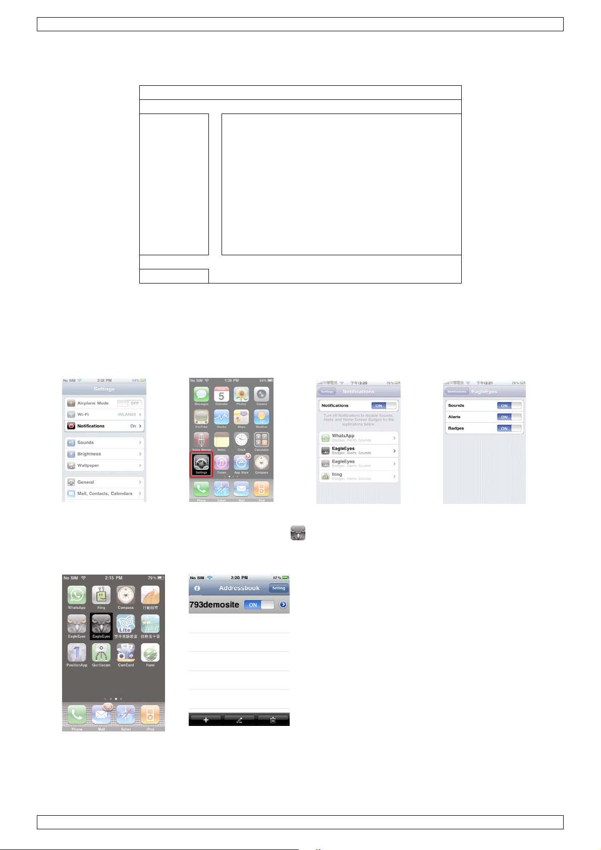
3. Read the introduction of the program if needed, and select INSTALL to start the installation.
4. Follow the on-screen instructions to download and install the program. The EagleEyes icon will be
shown on the mobile device’s desktop for quick access when the program is installed successfully.
Program setup
1. Select to enter the Address book, and select + at the bottom left corner to enter the device IP address
setting page.
2. Give a meaningful title to this IP setting, and enter the IP information needed to access this IVS DVR.
3. Make sure all the information is correct and select Save on the top right corner to save your setting and
return to the address book page.
4. To check whether your configurations are correct, select > to immediately access the DVR you just added.
You should be able to see the live view of the DVR.
Column Description
Required Column:
Title Give a meaningful title to this IP setting.
IP Address / Port Enter the IP address and port number used to access this DVR remotely.
Username / Password Enter the user name and password used to access thi s DVR remotely. The default user
name and password are both admin.
Get Type Click this button to detect the device type based on the IP data entered in the previous
columns, allowing users to check whether the device they want to connect is the right
device, and allowing the system to enable the functions and settings the device supports.
Optional Column:
Audio Click > to select the audio channel you want, and slide to enable or disable the audio
function.
Note: Before using this function, check whether the camera connected to this DVR
supports audio transmission and the connection is correct. For details, please refer to the
DVR user manual.
Format Select the network transmission format.
Quality Click > to select the image quality from Best, High, Normal or Basic.
V. 02 – 02/05/2012 15 ©Velleman nv
Page 16
IVSPROM2
Push notification on
Push notification must be enabled both on the DVR and on the mobile device.
1. Enter the ADVANCED CONFIG menu on the DVR and select NOTIFY.
ADVANCED CONFIG
CAMERA
DETECTION GUARD ON
ALERT CH1 LOBBY
NETWORK
DISPLAY
RECORD
DEVICES
DCCS
IVS
NOTIFY
EXIT
2. GUARD: Set to ON to activate the Push Notification function.
Note: For details about DVR operations from mobile devices, please visit http://www.eagleeyescctv.com.
3. CH1: Enter the text you want to see when your mobile device receives Push Notification. The default text is
the channel number.
4. In the iPhone/iPad main menu, select Settings > Notifications.
5. Make sure Notifications is set to ON.
6. Select EagleEyes, and make sure its settings are set to ON.
Note: This setting isn’t necessary for Android phones.
7. Return to the iPhone/iPad main menu, and select to enter the address book.
8. Select the title you just added, and make sure the button is set to ON to enable the Push Notification
support of this IVS DVR.
9. Trigger the human detection alarm and see if you are notified.
V. 02 – 02/05/2012 16 ©Velleman nv
Page 17
IVSPROM2
10. Set flow counting – virtual fence – one-way pass
Note: only available on the human detection camera.
Intelligent Video Surveillance (IVS) is the advanced application for motion detection, but more precise and
smarter. It can be applied to different situations with one of the following three modes: FLOW COUNTING,
VIRTUAL FENCE or ONE WAY.
Note: All four camera channels support this function.
On the DVR, right-click to show the main menu, and select > ADVANCED CONFIG > IVS.
ADVANCED CONFIG
CAMERA IVS1 IVS2 IVS3 IVS4
DETECTION CAMERA (For selected models only) CH3
ALERT IVS MODE FLOW COUNTING
NETWORK DISPLAY LINE OFF
DISPLAY SENSITIVITY 07
RECORD RESET COUNT SUBMIT
DEVICES VIRTUAL FENCE AREA SETUP
DCCS SCENE CHANGE OFF
IVS SCENE CHANGE SENSITIVITY MIDDLE
NOTIFY
EXIT
• CAMERA: Select the camera channel that you want to use the IVS function.
• IVS MODE: Select one of the following three modes depending on your environment:
MODE DESCRIPTION
FLOW COUNTING A virtual detection line is set to detect the moving direction of pedestrians for flow
counting.
VIRTUAL FENCE A virtual detection line is set to detect intruders crossing the detection line, and an
alarm will be triggered.
ONE WAY A virtual detection line is set to detect intruders from the specified direction, and an
alarm will be triggered.
• DISPLAY LINE: Select to display the detection line for IVS on the screen or not.
• SENSITIVITY: Set the sensitivity for IVS from 00 ~ 15. The larger the value, the more sensitive the IVS
will be.
• RESET COUNT: Click SUBMIT to reset the flow counting number to 0 when the IVS mode is set to FLOW
COUNTING and activated.
• VIRTUAL FENCE AREA: Click SETUP to draw the detection line for IVS, and set the detection direction
from left to right, or right to left. This area setting is the detection base for IVS MODE.
• SCENE CHANGE: Select ON to trigger a motion event when the camera is moved and the camera scene
changes. At the same time, the icon will also be shown on the screen in addition to the motion icon .
• SCENE CHANGE SENSITIVITY: Set the detection sensitivity for SCENE CHANGE to HIGH, MIDDLE
or LOW.
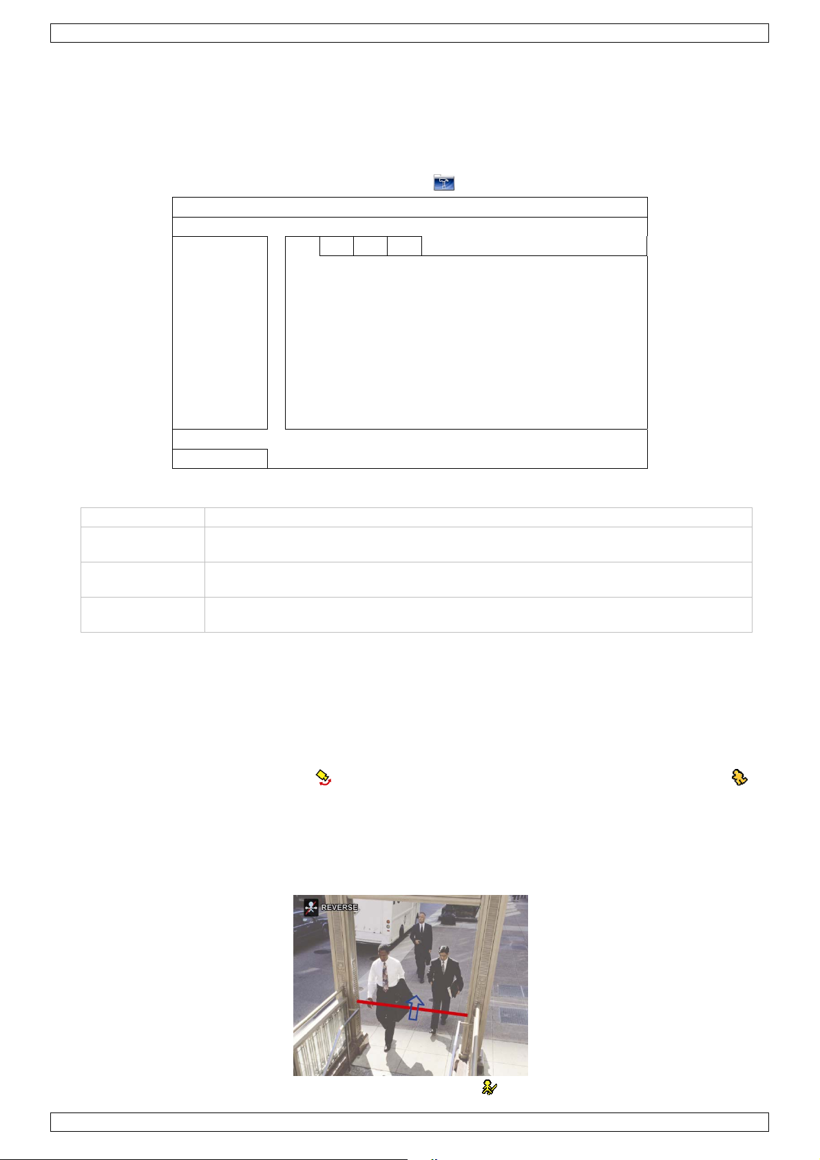
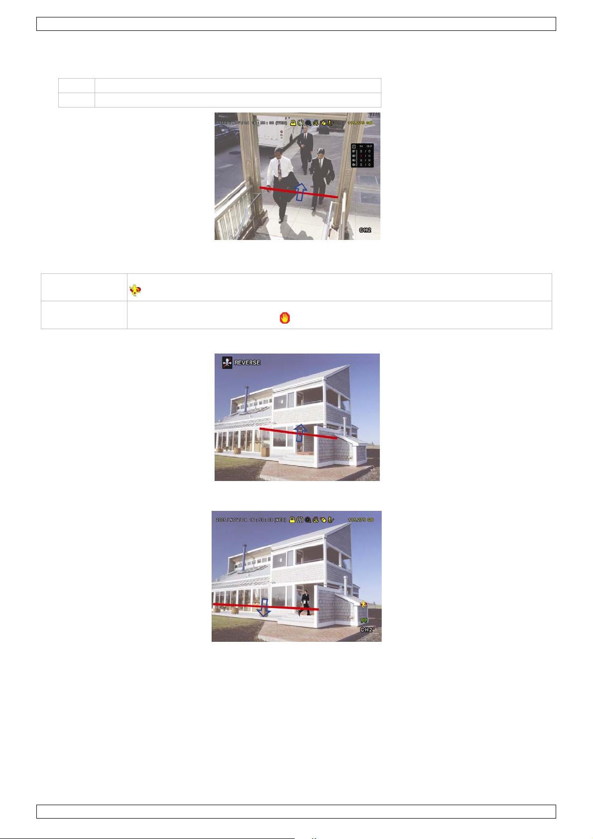
10.1 Flow counting
1. Go to VIRTUAL FENCE AREA to draw a detection line with your mouse, and decide the detection direction
by selecting REVERSE.
2. Finish the IVS setting and return to the live view. The IVS icon will be shown on the status bar.
V. 02 – 02/05/2012 17 ©Velleman nv
Page 18
IVSPROM2
3. Click it to show the flow counting panel as follows.
When anyone walks across the detection line, the system will determine his movement is in or out, and add
one count to the corresponding channel on the flow counting panel.
IN People coming from the opposite direction to the arrow mark.
OUT People coming from the same direction as the arrow mark.
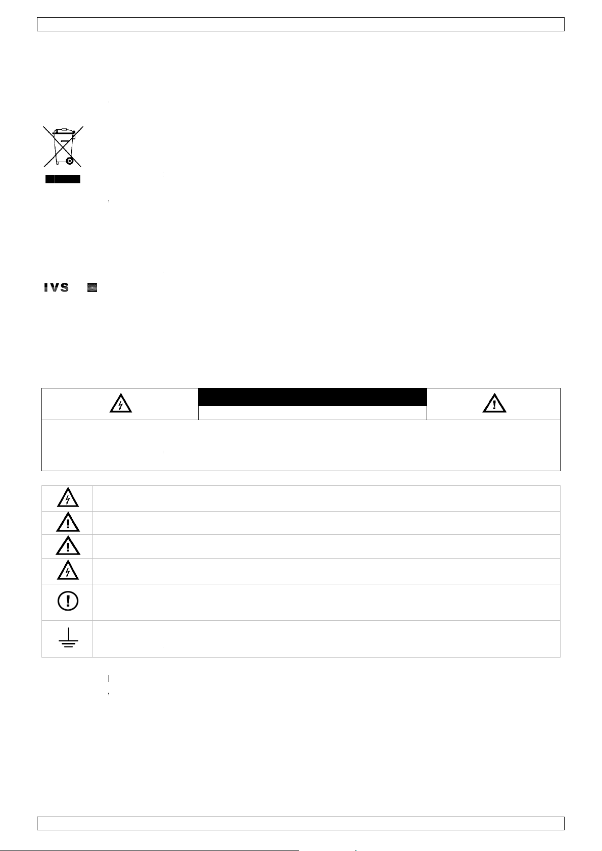
10.2 Virtual fence / one-way pass
VIRTUAL FENCE
ONE WAY
1. Go to VIRTUAL FENCE AREA to draw a detection line with your mouse, and decide the detection direction
by selecting REVERSE.
2. Finish the IVS setting and return to the live view.
When anyone walks across the detection line, the system will determine his movement is in or out.
An event is triggered when anyone walks across the detection line from any direction, and
is shown on the screen.
An event is triggered when anyone walking across the detection line from the opposite
direction of the arrow mark, and is shown on the screen.
V. 02 – 02/05/2012 18 ©Velleman nv
Page 19

IVSPROM2
10.3 IVS Statistics
1. Click and then to enter the event search menu. Select STATISTIC.
LIST
QUICK SEARCH CHANNEL
RECORD EVENT TYPE
MOTION
ALARM
TIME
HUMAN DETECTION
IVS MOTION
FULL
STATISTIC HARD DISK ALL HDD
TIME 2010/MAY/17
STATISTIC SUBMIT
EXIT
2. Set all the criteria you want to search, and click SUBMIT in STATISTIC to show the event statistics.
3. Click LIST or CHART to see the statistics in list or chart form.
4. To switch to the month or year view, click DAY at the bottom.
IVS STATISTIC
LIST CHART
HOUR COUNT
00:00 – 00:59 0
01:00 – 01:59 0
02:00 – 02:59 0
03:00 – 03:59 0
04:00 – 04:59 0
05:00 – 05:59 0
06:00 – 06:59 0
07:00 – 07:59 0
08:00 – 08:59 3
09:00 – 09:59 9
2010/MAY/17 DAY EXIT
;
01
02
;
INFLOW
OUTFLOW
VIRTUAL FENCE
ONE WAY
HUMAN DETECTION
ALARM
03
04
S
T
11. Technical specifications
IVS DVR: (Intelligent Video Security DVR)
video format NTSC/PAL (auto detect)
video compression H.264
video input 4 channels, composite video signal 1Vpp / 75 ohms BNC
video output
recording rate frame 704 × 576 pixels with 100 IPS (PAL)
recording speed adjustable for each channel
image quality setting super best - best - high - normal
hard disk storage SATA x2, support HDD capacity over 1TB (HDD not incl)
recording mode manual / timer / motion / alarm
multiplex operation live display, record, playback, backup and network
audio I/O 4 audio inputs, 1 audio output (mono)
motion detection area 16 x 12 grid per camera / 4 cameras
motion detection sensitivity 4 adjustable variables with precise calculation for motion detection
pre-alarm recording 8MB
V. 02 – 02/05/2012 19 ©Velleman nv
main monitor composite video signal 1Vpp / 75 ohms BNC
call monitor composite video signal 1Vpp / 75 ohms BNC
Page 20

IVSPROM2
backup device USB 2.0 backup and network remote backup
Ethernet 10/100 Base-T, supports remote control and LiveView via Ethernet
web interface supports licensed software AP / IE and Firefox browser
remote alarm notification e-mail images, and image uploading to specific FTP site accounts
network connection supports TCP/IP, PPPoE, DHCP and DDNS function
PTZ control supports PELCO-D protocol
alarm I/O 4 inputs, 1 output
digital zoom 2x
power source 19VDC (incl.)
power consumption < 42W
operating temperature 10°C ~ 40°C
system recovery system auto recovery after power reconnected
dimensions 343 x 59 x 223mm
Human detection camera
pick-up element 1/3" HR Colour CCD image sensor
number of pixels 752(H)x582(V) PAL
resolution 480 TV lines
IR LEDs 12
min. illumination 0.17 lux (F2.0) / 0 lux (IR on)
S/N ratio > 48dB (AGC off)
focal length f3.6mm / f2.0
lens
(standard)
lens angle 92°
electronic shutter 1/50 to 1/100 000 sec
AGC yes
white balance automatic
PIR detection range 5m
detection angle 40°
video output 1.0 Vpp composite / 75 ohms
power supply 12VDC
current consumption 110mA (IR off), 260mA (IR on)
operating temperature 0°C~45°C
dimensions 90 x 145 x 32mm
weight 220g
Use this device with original accessories only. Velleman nv cannot be held responsible in the event
of damage or injury resulted from (incorrect) use of this device.
For more info concerning this product and the latest version of this manual, please visit our website
www.velleman.eu.
The information in this manual is subject to change without prior notice.
© COPYRIGHT NOTICE
The copyright to this manual is owned by Velleman nv. All worldwide rights reserved.
No part of this manual may be copied, reproduced, translated or reduced to any electronic medium or otherwise
without the prior written consent of the copyright holder.
V. 02 – 02/05/2012 20 ©Velleman nv
Page 21
.
aBeHeDa
ewa
u
tlan
b
.
AOm
.
e
e
m
y
g
e
c
g
w
o
e
e
a
E
g
W
a
u
e
ocon
e
d
m
V
o
c
h
a
r
h
b
o
c
e
n
e
t
v
e
n
o
s
a
D
e
e
l
k
d
e
v
c
®
b
e
k
n
o
O
p
r
f
h
n
e
a
a
h
s
n
b
n
o
u
e
e
n
k
n
e
s
b
n
n
s
o
h
m
s
H
t
k
e
e
e
t
s
n
c
m
t
W
d
v
e
a
e
w
a
m
r
2
L
a
a
a
g
t
a
a
w
,
o
W
h
e
z
U
E
w
a
v
d
e
a
o
r
n
a
d
s
g
e
N
u
e
o
e
e
n
r
k
h
n
d
r
n
t
r
k
e
e
e
e
n
d
v
o
c
e
w
c
m
e
n
e
n
t
a
n
o
z
o
e
e
d
n
w
v
e
c
r
e
e
t
e
i
e
f
n
s
e
n
n
n
e
g
s
g
n
a
n
n
n
e
a
e
1
Inlei
A
n alle ing
langrijke
bt u vrage
nk u voor u
ge
bruiken. De
ze IVS vide
D
arschuwt h
is
itgerust. G
Be
kijk de dem
ht
p://www.e
en (
den.
All
e geregistre
en
kel gebruikt
fa
rikanten.
Ra
adpleeg de
ding
zetenen v
Dit s
weg
eworpen, d
batt
rijen) niet
tere
htkomen v
bren
n, contact
volledige E
bewakings
t onmiddell
o op http://
gleeyescct
agleEyes) –
erde handel
als voorbe
uitgebreide
ilieu-info
mbool op
en. Respe
aankoop!
makkelijk
K
n de Euro
matie bet
et toestel o
it toestel sc
ij het gewo
or recyclag
teer de pla
er dan de
Neem aand
gelstalige
t is het eer
ijk een mob
e installere
www.youtu
.com/.
Aanvraag
smerken en
ld van de c
handleiding
RTE
ese Unie
effende di
de verpak
ade kan to
e huishoud
. U moet di
tselijke mili
plaatselijk
chtig de ui
andleiding i
te intellige
iel toestel (i
en met vel
e.com/wat
aar registra
handelsna
mpatibilitei
op de cd-ro
IVSPROM
AND
product
ing geeft a
brengen a
elijke afval;
t toestel na
uwetgevin
autoritei
gebreide h
beschikba
te DVR be
Phone, iPad
e functies z
h?v=DKKz
tie van het
en zijn eig
tussen on
m voor mee
EIDI
n dat, als h
n het milie
het moet bi
r uw verdel
.
en betreff
ndleiding d
r op de me
akingsyste
Android ph
als herken
JAg7Lw of
andelsmer
ndom van
e producte
r info over
G
et na zijn le
. Gooi dit t
j een gespe
er of naar e
nd de ver
or alvorens
geleverde
m ter werel
one…) dat
ing en telle
aadpleeg d
is ingedie
un respecti
en de prod
e rechten.
enscyclus
estel (en e
ialiseerd b
n lokaal re
ijdering.
deze came
d-rom.
d. Bij alarm
et de Eagl
n van mens
IVS websi
d in de VS
velijke bez
ucten van d
ordt
entuele
drijf
yclagepunt
a te
belt en
Eyes-softw
n.
e op
n andere
tters, en zij
verschille
re
n
de
2
Veili
W
ARSCHU
elektrocut
chtigheid. G
vo
niet aanspr
is
Dit
de
Dit
Ho
El
om
De
do
To
sto
on
heidsi
ING:
iegevaar tot
ebruik het t
kelijk voor
symbool w
behuizing.
symbool ga
d buiten h
ktrocutieg
dodelijke e
behuizing
r de gebrui
tacteer uw
stel veiligh
pcontact. El
erbreking
structie
een minim
estel enkel
chade bij v
arschuwt d
eze spanni
at belangrij
t bereik va
vaar bij h
ektroshock
mag NIET
er vervang
ealer.
idsklasse 1
ke onderbre
an de aardi
s
ELE
m te herlei
met de voe
rkeerd geb
gebruiker
g kan elekt
e informati
kinderen e
t openen v
te vermijd
geopend
are onderd
(voedingsk
king van de
g is verbod
AARSCH
KTROCUTI
en, moet u
dingsspanni
ruik van dit
an de aan
rocutiegeva
vooraf in
n onbevoeg
n het toest
n. Laat rep
orden tenz
elen in dit t
bel met aa
aarding ka
en.
WING
GEVAAR
het toestel
ng zoals ve
toestel.
ezigheid va
r oplevere
erband me
en.
l. Raak gee
raties over
ij anders ve
estel. Voor
ding). Stee
elektrocuti
bescherme
meld op he
n een geva
.
het onderh
n kabels aa
aan gescho
meld in de
onderhoud
de stekker
gevaar opl
tegen rege
toestel zel
rlijke span
oud van dit
die onder
ld persone
e handleidi
f reserveo
enkel in ee
veren. Opz
n en
. Velleman
ing binneni
toestel.
troom staa
l.
g. Er zijn g
derdelen,
geaard
ttelijke
v
n
en
3
Alge
Ra
adpleeg de
m
egeleverde
•
Enkel vo
geen obje
Bescherm
•
Bescherm
•
Leer eerst
•
Om veilig
•
aangebrac
V.
02 – 02/05/2
ene ri
elleman
cd-rom).
r gebruik
ten gevuld
tegen stof
tegen scho
de functies
eidsredene
ht valt niet
012
htlijne
service- e
innenshui
met vloeist
n extreme
ken en ver
van het toe
mag u gee
nder de ga
n kwaliteit
. Bescher
f op het toe
itte. Zorg v
ijd brute k
tel kennen
n wijziginge
rantie.
sgarantie
tegen rege
stel.
oor voldoen
acht tijden
voor u het
n aanbreng
21
chteraan d
n, vochtigh
e ventilati
de bedieni
aat gebruik
n. Schade
uitgebreid
id en opspa
ruimte ron
g.
en.
oor wijzigi
handleidin
ttende vloei
om het toe
gen die de
(zie
stoffen. Pla
tel.
ebruiker h
©Vellema
ts
eft
nv
Page 22
IVSPROM2
• Gebruik het toestel enkel waarvoor het gemaakt is. Bij onoordeelkundig gebruik vervalt de garantie.
• De garantie geldt niet voor schade door het negeren van bepaalde richtlijnen in deze handleiding en uw
dealer zal de verantwoordelijkheid afwijzen voor defecten of problemen die hier rechtstreeks verband mee
houden.
• Bewaar deze handleiding voor verdere raadpleging.
• Leef bij gebruik van dit toestel de wetgeving betreffende de privacy na.
4. Eigenschappen
De IVS bewakingset heeft volgende eigenschappen:
Mensenstroom
De virtuele muur bepaalt de richting van de
mensenstroom.
Virtuele muur
Waarneming van alle indringers die de virtuele muur
overtreden.
Bewaking op afstand
Eagle Eyes voor bewaking op afstand. De
EagleEyes-software is compatibel met de
meeste populaire platformen zoals iPhone,
Android, BlackBerry, Windows Mobile en
Symbian.
DCCS-technologie (communicatie tussen DVR/camera):
Deze technologie zendt het signaal direct over een coaxkabel naar de camera. Zo wordt de
installatie vereenvoudigd en worden de werkuren aanzienlijk verminderd.
IVS detectiecamera
• de ingebouwde infrarood sensor neemt personen waar en zendt een bericht naar een mobiel toestel
(iPhone, iPad, Android phone…).
• compatibel met DCCS-technologie
o directe overdracht van het signaal via de coaxkabel, dus geen extra RS485-kabels nodig
o vereenvoudigde installatie en een aanzienlijke vermindering van de installatiekosten.
• ingebouwde infraroodleds voor een bewaking overdag en ‘s nachts
• een helder en precies beeld dankzij Smart Light Control
Waarschuwing via mobiel toestel
Onmiddellijke waarschuwing naar een mobiel toestel
(iPhone, iPad, Android phone…) voor een directe
toegang op afstand bij waarneming door de
bewakingscamera.
Systeem
• bediening via grafische display en USB-muis
• compatibel met Gmail en andere e-mailservices
• lokale bediening en bediening op afstand volledig afzonderlijk
• ingebouwde VGA-interface met een resolutie tot 1600 x 1200
• inhoud:
o 1 x 4-kanaals H.264 Full frame DVR
o 1 x PIR-camera
V. 02 – 02/05/2012 22 ©Velleman nv
Page 23

IVSPROM2
o 1 x infrarood afstandsbediening
o 1 x camerakabel van 20m
o 1 x 19V voedingsadapter
o 1 x high-efficiency DC-DC converter voor de DVR en 4 camera's.
• optionele harde schijven (niet meegeleverd): 500 GB (HD500GB/S) of 1 TB (HD1TB/S)
• infrarood afstandsbediening: DVRRC4 (meegeleverd)
• optionele monitor (niet meegeleverd): MONSCA4, MONSCA5, MONSCA6, MONSCA7
• optionele router (niet meegeleverd): PCRT1, EM4542, EM4553, EM4570.
5. Aansluiting en instelling
Alvorens de DVR in te schakelen, zorg dat de harde schijf geïnstalleerd is en sluit minstens één camera en een
monitor aan.
Opmerking: De DVR zal het videosysteem van de aangesloten camera’s (NTSC/PAL) automatisch herkennen.
Zorg er dus eerst voor dat de camera’s op de DVR en een voedingsbron zijn aangesloten.
5.1 Richtlijnen vooraf
• Om een goede signaaloverdracht te garanderen, raden wij aan om de aansluitlengte tussen de DVR en de
camera’s bij gebruik van 3C2V coaxkabels te beperken tot maximaal 200 m.
Het gebruik van andere types coaxkabels of een langere aansluiting kan de signaaloverdracht negatief
beïnvloeden.
• Gebruik geen signaalbooster of modem om de signalen bij lange aansluitingen te versterken.
5.2 Installatie van de hardware
Raadpleeg de afbeeldingen op pagina 3 van deze handleiding.
Aansluiting van een videomonitor
Sluit een compatibele monitor (niet meegeleverd) aan de BNC of VGA video-uitgang achteraan uw DVR.
Opmerking: De CAL video-uitgang geeft enkel de camerabeelden weer. Data en/of bedieningen vanaf de
hoofdmonitor worden niet weergegeven.
Aansluiting van de voedingsadapter
1. Steek de DC-stekker van de adapter in de 19 VDC-ingang achteraan de DVR.
WAARSCHUWING: Gebruik enkel de meegeleverde voedingsadapter.
2. Koppel de voedingskabel aan de adapter en koppel de adapter vervolgens aan het lichtnet. Schakel de
DVR nog niet in.
Aansluiting van een camera
1. Kies een montageplaats voor de camera en let er op:
o dat u de camera niet installeert op een plaats onderhevig aan trillingen en extreem hoge of l age
temperaturen
o dat u de camera niet installeert op een plaats onderhevig aan magnetische velden
o dat u de camera niet richt naar de zon of een ander helder voorwerp.
2. Sluit de video-uitgang van de camera aan op de video-ingang van de DVR met behulp van de meegeleverde
kabels. Het cijfer naast de ingangsaansluiting duidt op het kanaalnummer. De connector is van het type
BNC.
3. Sluit elke camera aan op de voedingsbron.
Opmerking: Zorg dat de camera’s op de DVR en een voedingsbron zijn aangesloten voor u de DVR inschakelt.
Audioaansluiting
• De DVR heeft vier audio-ingangen. Sluit de audio-uitgang van de audiobron aan de audi o-ingang van de
DVR. Zorg ervoor dat u het audiokanaal aansluit op het correcte videokanaal. Gebruik hiervoor een stekker
van het type RCA.
• De DVR heeft ook een RCA audio-uitgang naar een extern audiotoestel, bv. een luidspreker.
Opmerking: De camera’s geleverd bij de IVSPROM2 kunnen geen geluid opnemen.
Aansluiting aan een LAN-netwerk
Sluit de DVR via een netwerkkabel aan een LAN-netwerk. Gebruik hiervoor een stekker van het type 8P8C
(RJ45). De instellingen gebeuren via het instelmenu.
V. 02 – 02/05/2012 23 ©Velleman nv
Page 24

IVSPROM2
5.3 Inschakeling van de DVR
1. Gebruik dit toestel enkel met een compatibele voedingsbron (zie label). Koppel de DVR aan het lichtnet via
de meegeleverde voedingskabel.
Opmerking: Alvorens de DVR in te schakelen, zorg dat (1) de camera op de DVR en een voedingsbron
aangesloten is en dat (2) een monitor (lcd- of CRT-monitor, niet meegeleverd) op de DVR aangesloten is.
2. Schakel de DVR in met de voedingsschakelaar achteraan het toestel. De DVR is na 30 seconden
geïnitialiseerd.
Opmerking: Het is aan te raden om een UPS-voeding (niet meegeleverd) te gebruiken.
5.4 Instelling van datum en tijd
Stel voor elk gebruik van de DVR datum en tijd in.
Opmerking: Stel nooit datum en tijd in na het starten van de opnamefunctie om verwarring bij het zoeken van
bestanden te vermijden. Bij onopzettelijke wijziging is het aan te raden om alle gegevens te verwijderen en de
opnames te herbeginnen.
Opmerking: Bij het eerste gebruik laat u de DVR, na datum- en tijdinstelling, best gedurende 48 uur
ingeschakeld. Om de interne batterij te vervangen, zie APPENDIX 6 in de uitgebreide handleiding.
1. Klik met de rechtermuisknop om het paswoord in te typen. Het standaard paswoord is 0000.
De status wijzigt van (toetsen vergrendeld) naar (administrator).
2. Klik met de rechtermuisknop om het hoofdmenu weer te geven. Selecteer QUICK START > TIME SETUP
om datum en tijd in te stellen.
QUICK START
GENERAL DATE 2009 / NOV / 17
TIME SETUP TIME 15 : 35 : 53
EXIT
5.5 Wissen van de harde schijf
Het is aan te raden om eerst alle gegevens op de harde schijf te wissen zodat de nieuwe opnames niet met
oude verward kunnen worden.
1. Klik met de rechtermuisknop om het hoofdmenu weer te geven. Selecteer SYSTEM > SYSTEM INFO >
CLEAR HDD.
2. De DVR herstart na het wissen van de harde schijf. Raadpleeg §5.3.2 in de uitgebreide handleiding voor
meer details.
SYSTEM
TOOLS BAUD RATE 2400
SYSTEM INFO HOST ID 000
USB BACKUP R.E.T.R 5
DVD BACKUP AUTO KEY LOCK NEVER
CLEAR HDD HDD-0
RESET DEFAULT SUBMIT
REMOTE CONTROL ID 000
SERIAL TYPE RS485
VIDEO FORMAT NTSC
VERSION 1019-1008-
1010-1010
EXIT
V. 02 – 02/05/2012 24 ©Velleman nv
Page 25
IVSPROM2
5.6 Instellen van het paswoord
1. Klik met de rechtermuisknop om het hoofdmenu weer te geven. Selecteer SYSTEM > TOOLS om het
paswoord te wijzigen.
2. Er zijn twee gebruikersniveaus: ADMIN en OPERATOR. Raadpleeg 5.3.1 TOOLS in de uitgebreide
handleiding voor meer details.
SYSTEM
TOOLS LANGUAGE ENGLISH
SYSTEM INFO ADMIN PASSWORD SETUP
USB BACKUP OPERATOR PASSWORD SETUP
DVD BACKUP UPGRADE SUBMIT
BACKUP CONFIG SUBMIT
RESTORE CONFIG SUBMIT
EXIT
6. GUI-display met USB-muis
6.1 Aansluiting van een USB-muis
1. Sluit een USB-muis (niet meegeleverd) aan op de muispoort op het frontpaneel. Het muissymbool
verschijnt op het scherm.
2. Beweeg de muis om het paswoord via het keypad in te geven. Het standaard paswoord is 0000.
De status wijzigt van (toetsen vergrendeld) naar (administrator). Het snelmenu verschijnt links op het
scherm.
Opmerking: Het menu van de DVR is bereikbaar vanaf twee gebruikersniveaus (instelbaar vanaf het
hoofdmenu SYSTEM > TOOLS).
Invoer van het paswoord Snelmenu (gesloten)
6.2 Snelmenu
Beweeg de muispointer naar de linkerkant van het scherm om het snelmenu te openen. Het menu bevat zes
functies:
Snelmenu (geopend)
V. 02 – 02/05/2012 25 ©Velleman nv
Page 26
IVSPROM2
Keuzepaneel kanalen of schermindeling.
Afspeelvenster. Klik op om de laatste opname af te spelen of klik op om een bestand te zoeken.
Kies het gewenste kanaal en klik op om in te zoomen. Klik en sleep het rode frame onderaan links
om u in het beeld te verplaatsen. Klik op 7 om opnieuw uit te zoomen.
Keuze audiokanaal.
Tijdens de live waarneming kunnen enkel de live audiokanalen geselecteerd worden.
Tijdens het afspelen van een bestand kan zowel live als opgenomen geluid geselecteerd worden.
PTZ-besturing en PTZ-bedieningen (indien van toepassing).
Uitschakelen of herstarten.
6.3 Hoofdmenu
Klik met de rechtermuisknop in het scherm om het hoofdmenu weer te geven of te verbergen.
Hoofdmenu
Structuur hoofdmenu
*: niet beschikbaar op alle modellen
QUICK START: Display-, beeld-, datum- en tijdinstellingen.
GENERAL
TIME SETUP DATE - TIME
DATE SETUP: Datum- en zomeruurinstellingen.
DATE INFO DISPLAY DATE OF MODE – FORMAT
DAYLIGHT DAYLIGHT SAVING
SYSTEM: Systeemconfiguratie.
TOOLS
SYSTEM INFO
BACKUP DATA (USB)
BACKUP LOG (USB)
EVENT INFORMATION: Zoekfunctie.
QUICK SEARCH
EVENT SEARCH
HDD INFO
EVENT LOG
ADVANCED CONFIG: Instellingen CAMERA, DETECTION, ALERT, NETWORK, DISPLAY, RECORD,
DEVICES, DCCS, IVS* & NOTIFY*.
CAMERA
DETECTION LS – SS – TS – MOTION – ALARM - AREA
CHANNEL TITLE – EVENT STATUS – DATE DISPLAY – DCCS DISPLAY – MOUSE
SENSITIVITY – PRIORITY* – RECORD CONFIG
LANGUAGE – ADMIN PASSWORD – OPERATOR PASSWORD – UPGRADE BACKUP CONFIG – RESTORE CONFIG
BAUD RATE – HOST ID – R.E.T.R. – AUTO KEY LOCK – CLEAR HDD – RESET
DEFAULT – REMOTE CONTROL ID – SERIAL TYPE – VIDEO FORMAT – VERSION
BRIGHTNESS – CONTRAST – SATURATION – HUE - COV. – REC - CHANNEL
TITLE
V. 02 – 02/05/2012 26 ©Velleman nv
Page 27
IVSPROM2
EXT. ALERT – INT. BUZZER – KEY BUZZER – VLOSS BUZZER – MOTION BUZZER
ALERT
NETWORK NETWORK – SNTP – FTP – E-MAIL
DISPLAY
RECORD
DEVICES
DCCS
IVS*
NOTIFY* GUARD
SCHEDULE SETTING: Timerinstellingen opname en waarneming.
RECORD
DETECTION
ALARM
– ALARM BUZZER – HDD BUZZER – ALARM DURATION (SEC) – HDD NEARLY
FULL (GB)
DE-INTERLACE* – FULL SCREEN DURATION – QUAD SCREEN DURATION* –
CALL SCREEN DURATION – DISPLAY COVERT – HDD DISPLAY MODE – VIDEO
OUTPUT* – ALPHA BLENDING – VGA OUTPUT – VGA DEINTERLACE* –
COMPOSITE DEINTERLACE*
MANUAL RECORD – EVENT RECORD – TIMER RECORD – PRE-ALARM RECORD –
OVERWRITE – EVENT RECORD ALL CH – KEEP DATA LIMIT (DAYS) – RECORD
CONFIG
CAMERA* – IVS MODE – DISPLAY LINE – SENSITIVITY – RESET COUNT –
VIRTUAL FENCE AREA – SCENE CHANGE – SCENE CHANGE SENSITIVITY
7. Front- en achterpaneel
7.1 Frontpaneel
• Leds
DVR ingeschakeld.
Harde schijf is aan het lezen of aan het opnemen.
Alarm ingeschakeld.
Timeropname.
Afspelen bestand.
• : Lade openen/sluiten (enkel voor modellen met dvd-speler).
• 1 ~ 4: Druk op een cijfer om het overeenstemmende kanaal te selecteren.
• : Vierdelige schermopstelling.
• SEQ: Sequentiële weergave van de kanalen vanaf het eerste kanaal. Verlaat de functie door opnieuw op
SEQ te drukken.
• SLOW: Vertraagd afspelen.
• ZOOM: Inzoomen van het geselecteerde kanaal (enkel in formaat FRAME of FIELD).
• PLAY: Afspelen laatste opname.
• LIST: Zoekfunctie: RECORD / MOTION / ALARM / TIME / HUMAN DETECTION / IVS / STATISTIC, of
selecteer FULL om alle gebeurtenissen weer te geven.
Selecteer QUICK SEARCH om snel volgens tijdstip te zoeken. Raadpleeg de uitgebreide handleiding voor
meer details.
• MENU: Weergave hoofdmenu.
• ENTER: Bevestigen instelling.
• : ▲ / ▼ / ◄ / ►: omhoog / omlaag / links / rechts.
Tijdens het afspelen:
: pauzeren.
: stoppen.
: vooruitspoelen.
: terugspoelen.
V. 02 – 02/05/2012 27 ©Velleman nv
Page 28

IVSPROM2
• AUDIO (SLOW + ZOOM): Selecteren live of bestandsaudio voor kanaal 1~4.
Live audio voor kanaal 1~4 (wit).
Audio uitgeschakeld.
• P.T.Z. ( + SEQ): PTZ-bedieningen.
• USB-poort: Er zijn twee USB-poorten, één voor de aansluiting van de USB-muis en één voor de aansluiting
van een USB flashdrive.
Opmerking: Sluit nooit gelijktijdig twee USB-muizen of twee USB flashdrives aan op de DVR.
Opmerking: Raadpleeg APPENDIX 3 in de uitgebreide handleiding voor een lijst met compatibele USB-
muizen.
Bestandsaudio voor kanaal 1~4 (geel).
7.2 Achterpaneel
• VIDEO IN (1 ~ 4): Aansluiting voor de camera.
Opmerking: De DVR herkent automatisch het videosysteem van de camera. Zorg dat u de camera’s
correct aansluit op de DVR en de voedingsbron alvorens de DVR in te schakelen.
• AUDIO IN (1~4): Ingang voor de audio-aansluiting van de camera (enkel voor camera met audio).
Opmerking: Zorg dat, indien u een opname met audio wenst, de camera zowel op de video-ingang als
audio-ingang is aangesloten.
• AUDIO OUT: Mono audio-uitgang naar de luidspreker.
• MONITOR: Videoaansluiting voor de CRT-monitor.
Opmerking: De aansluiting op een CRT-monitor ondersteunt tevens een gelijktijdige aansluiting op een
LCD-monitor voor een dubbele video-uitgang.
• CAL: Aansluiting voor een callmonitor.
• VGA: Directe aansluiting voor een lcd-monitor.
Opmerking: De aansluiting op een LCD-monitor ondersteunt tevens een gelijktijdige aansluiting op een
CRT-monitor voor een dubbele video-uitgang.
• IR: Aansluiting voor een infrarood ontvanger (niet meegeleverd).
• EXTERNAL I/O: Aansluiting voor externe toestellen zoals een koepelcamera, extern alarm, enz.
• LAN: LAN-aansluiting.
• DC 19V: Aansluiting voor de meegeleverde voedingsadapter.
• :Voedingsschakelaar. Plaats op | om in te schakelen of op | om uit te schakelen.
8. Basisfuncties
Opmerking: Bepaalde functies die hieronder beschreven worden, zijn enkel geldig voor de PIR-camera.
8.1 Live weergave
Raadpleeg de afbeeldingen hieronder.
1 systeemtijd
2 statusbalk
3 beschikbare schijfruimte
4 opnamesymbool
5 kanaal
6 bewegingsymbool
Functie Functie Functie
live audio (1~4)
inzoomen
V. 02 – 02/05/2012 28 ©Velleman nv
bestandsaudio (1~4)
uitzoomen
audio uitgeschakeld
opname met timer
Page 29

IVSPROM2
Functie Functie Functie
netwerkprobleem
USB-muis aangesloten
toetsvergrendeling
administrator
opname
virtuele muur
beweging waargenomen
Opnamemodus: Frame
DCCS-aansluiting OK
internetaansluiting
USB flashdrive aangesloten
PTZ-besturing ingeschakeld
gebruiker
alarm
‘one-way pass’
mensentelling
Opnamemodus: Field
DCCS-aansluiting mislukt
LAN-aansluiting
USB flashdrive ontkoppeld
overschrijven harde schijf
sequentiële weergave
bewegingswaarneming
cameraverplaatsing
Smart Zoom
Opnamemodus: CIF
8.2 Opname
• Handmatige opname
Standaard is de handmatige opnamefunctie ingeschakel d.
• Opname na bewegingswaarneming
De symbolen / / / / / staan op het scherm weergegeven (afhankelijk van gebeurtenis).
• Opname met timer
Het symbool verschijnt op het scherm.
• Overschrijven harde schijf
Standaard staat deze functie ingeschakeld en verschijnt het symbool op het scherm.
8.3 Opname afspelen
Klik op om de bedieningsbalk weer te geven. Klik op om de laatste opname af te spelen of op om de
zoekfunctie in te schakelen.
Raadpleeg de afbeelding hieronder:
1 statusbalk 4 bedieningen
2 sluiten 5 zoekfunctie
3 informatiebalk
Opmerking: Een bestand moet minstens 8192 frames bevatten om afgespeeld te kunnen worden.
Voorbeeld: Indien het videobestand aan 30 ips werd opgenomen, dan zal de opnameduur van dit bestand
minstens 273 seconden moeten bedragen (8192 frames / 30 ips).
Opmerking: Tijdens het afspelen wordt het beeldformaat van de opname (FRAME, FIELD of CIF) op het
scherm weergegeven.
Bedieningen
/
/
vooruitspoelen 1x klikken: 4x snelheid; 2x klikken: 8x snelheid … Maximale snelheid: 32x.
terugspoelen 1x klikken: 4x snelheid; 2x klikken: 8x snelheid … Maximale snelheid: 32x.
afspelen/pauze
stoppen Klik om het videobestand te stoppen.
traag afspelen 1x klikken: 1/4x snelheid; 2x klikken: 1/8x snelheid …
vorige/volgende
Klik om de laatste opname af te spelen/te pauzeren.
Klik eenmaal op / om frame per frame achteruit/vooruit te spoelen.
Verspring naar het vorige/volgende interval. Voorbeeld: 11:00 > 12:00 of
15:00 > 14:00.
V. 02 – 02/05/2012 29 ©Velleman nv
Page 30

IVSPROM2
herhalen
Back-up Klik om het back-up menu te openen voor de back-up van videobestanden.
Zoekfunctie
• Klik op om de bestanden volgens RECORD / MOTION / ALARM / TIME / HUMAN DETECTION / IVS /
STATISTIC op te zoeken. Selecteer optie FULL om alle bestanden weer te geven.
• Selecteer QUICK RESEARCH om te zoeken volgens tijdstip. Raadpleeg §5.4.1 in de uitgebreide handleiding
voor meer details.
Audioweergave
Klik tijdens het afspelen van een bestand op en selecteer live of opgenomen geluid voor kanalen 1~4.
Live audio voor kanaal 1~4
(wit).
Opmerking: Zorg dat, indien u een opname met audio wenst, de camera zowel op de video-ingang als audioingang is aangesloten.
Klik om punt A en punt B in te stellen in een opname, en het systeem zal enkel de
geselecteerde opname afspelen in dat videobestand.
Bestandsaudio voor kanaal 1~4
(geel).
Audio uitgeschakeld.
8.4 Gebruiker selecteren
• Beweeg, indien de toetsen vergrendeld zijn , de USB-muis en geef het paswoord in. De DVR heeft twee
gebruikersniveaus: administrator en gebruiker .
• Na het invoeren van het administratorpaswoord verschijnt het symbool in de statusbalk. De
administrator heeft toegang tot alle functies. Het standaard paswoord is 0000.
• Na het invoeren van het gebruikerspaswoord verschijnt het symbool in de statusbalk. Een gewone
gebruiker heeft echter geen tot het hoofdmenu. Stel de toegangsmogelijkheid van de gebruiker in onder
SYSTEM > TOOLS.
• Schakel tussen administrator en gebruiker door op het symbool van de huidige gebruiker te klikken.
Beweeg nu de USB-muis en geef het paswoord van de gewenste gebruiker in.
8.5 Video-uitgang selecteren
De DVR ondersteunt simultaan een CRT-scherm (MONITOR-aansluiting) en een lcd-scherm (VGA-aansluiting).
Om de video-uitgang te selecteren:
1. Bij een ingeschakelde DVR, klik met de rechtermuisknop in het scherm om het hoofdmenu weer te geven.
Selecteer daarna ADVANCED CONFIG > DISPLAY > VIDEO OUTPUT.
2. Selecteer BOTH om simultaan beelden weer te geven op zowel LCD- als CRT-schermen; selecteer VGA
voor beeldweergave op een LCD-scherm; selecteer COMPOSITE voor beeldweergave op een CRT-scherm.
ADVANCED CONFIG
CAMERA DE-INTERLACE (For Selected Models Only) OFF
DETECTION FULL SCREEN DURATION 03
ALERT QUAD SCREEN DURATION (For Selected Models Only) 03
NETWORK CALL SCREEN DURATION 03
DISPLAY DISPLAY COVERT ON
RECORD HDD DISPLAY MODE HDD SIZE
DEVICES VIDEO OUTPUT (For Selected Models Only) BOTH
DCCS ALPHA BLENDING 200
IVS VGA OUTPUT 1024 X 768
NOTIFY VGA DEINTERLACE (For Selected Models Only) ON
COMPOSITE DEINTERLACE(For Selected Models Only) ON
EDIT
V. 02 – 02/05/2012 30 ©Velleman nv
Page 31

IVSPROM2
9. Instellen van de meldingfunctie
Opmerking: Enkel beschikbaar op de PIR-camera.
Deze DVR ondersteunt de meldingfunctie via een mobiel toestel (iPhone, iPad, Androi d…) met de EagleEyessoftware. Na een alarm stuurt de DVR automatisch een melding van de gebeurtenis naar uw mobiel toestel.
Opmerking: EagleEyes is krachtige bewakingsoftware ontworpen door AV TECH Corporation. Raadpleeg
http://www.eagleeyescctv.com voor meer informatie over EagleEyes.
Contacteer Velleman nv (www.velleman.eu) indien u vragen hebt over EagleEyes.
Het gebruik van deze software met uw mobiel toestel vereist enkele instellingen.
9.1 Richtlijnen vooraf
Voer eerst volgende handelingen uit alvorens uw mobiel toestel in te stellen:
1. Installeer EagleEyes op uw mobiel toestel (iPhone, iPad, Android phone…). Zie Downloaden van de
software hieronder voor meer informatie.
2. Sluit een camera aan op uw DVR.
3. Schakel de opnamefunctie (EVENT) in op de DVR.
4. Schakel de bewegingswaarneming in op de DVR.
5. Sluit de DVR aan op een internetverbinding. Raadpleeg
http://www.surveillance-download.com/user/CMS.pdf voor meer details.
6. Zorg dat de DVR over het internet beschikbaar is via een computer op een ander netwerk dan dat van
de DVR.
9.2 Instellen van het mobiel toestel
Downloaden van de software
1. Open de App Store op uw iPhone/iPad
2. Type eagleeyes in het zoekvenster.
Opmerking: Raadpleeg uw netwerkprovider voor alle eventuele internetaansluitingtarieven.
3. Selecteer INSTALL om de installatieprocedure te starten.
4. Volg de instructies op het scherm. Het EagleEyes-icoontje verschijnt op het bureaublad van uw mobiel
toestel.
Instellen van de software
1. Klik op om het adressenboek weer te geven. Klik daarna op + onderaan het scherm om het IP-venster
weer te geven.
of ga naar de Android/Google Play market met uw Android telefoon.
2. Type de nodige gegevens correct in.
3. Klik op Save bovenaan rechts om alle gegevens te bewaren en naar het adressenboek terug te keren.
V. 02 – 02/05/2012 31 ©Velleman nv
Page 32

IVSPROM2
4. Klik vervolgens op > om verbinding te zoeken met de DVR. Als u alle gegevens correct hebt ingevuld, zou u
live beelden op het scherm te zien moeten krijgen.
Kolom Omschrijving
Vereist
Title Geef hier de naam in.
IP Address / Port Geef het IP-adres en poortnummer van de DVR in.
Username / Password Geef gebruikersnaam en paswoord in. Standaard gebruikersnaam en paswoord zijn
admin.
Get Type Klik op deze knop om het toesteltype weer te geven afhankelijk van het ingegeven IP-
adres.
Optioneel
Audio Klik op > om het audiokanaal te selecteren. Verschuif de knop om de audio in of uit te
schakelen.
Opmerking: Controleer eerst of de aangesloten camera een audiofunctie heeft.
Raadpleeg de handleiding van de DVR voor meer details.
Format Selecteer het netwerkformaat.
Quality Klik op > om de beeldkwaliteit te selecteren (Best, High, Normal, Basic).
Inschakelen van de meldingfunctie
Schakel de meldingfunctie in op zowel de DVR als op uw mobiel toestel.
1. Open ADVANCED CONFIG op de DVR en selecteer NOTIFY.
ADVANCED CONFIG
CAMERA
DETECTION GUARD ON
ALERT CH1 LOBBY
NETWORK
DISPLAY
RECORD
DEVICES
DCCS
IVS
NOTIFY
EXIT
2. GUARD: Selecteer ON om de functie in te schakelen.
Opmerking: Raadpleeg http://www.eagleeyescctv.com voor meer details over het besturen van de DVR
via uw mobiel toestel.
3. CH1: Geef hier uw meldingsbericht in. Het standaard bericht is het kanaalnummer.
4. Selecteer Settings > Notifications in het hoofdmenu van de iPhone/iPad.
5. Selecteer ON onder Notifications.
V. 02 – 02/05/2012 32 ©Velleman nv
Page 33

IVSPROM2
6. Selecteer EagleEyes en daarna ON.
Opmerking: Dit hoeft niet ingesteld te worden op een Android smartphone.
7. Keer terug naar het hoofdmenu van uw iPhone/iPad en selecteer om het adresboek weer te geven.
8. Kies de ingegeven naam en selecteer ON om de functie in te schakelen.
9. Test de functie door het alarm in te schakelen.
10. Mensentelling – virtuele muur – mensenstroom
Opmerking: Enkel beschikbaar op de PIR-camera.
De IVS-technologie is een geavanceerde en preciezere bewegingswaarneming en biedt volgende functies: FLOW
COUNTING, VIRTUAL FENCE of ONE WAY.
Opmerking: Alle vier kanalen ondersteunen de functies.
Klik met de rechtermuisknop en selecteer > ADVANCED CONFIG > IVS.
ADVANCED CONFIG
CAMERA IVS1 IVS2 IVS3 IVS4
DETECTION CAMERA (For selected models only) CH3
ALERT IVS MODE FLOW COUNTING
NETWORK DISPLAY LINE OFF
DISPLAY SENSITIVITY 07
RECORD RESET COUNT SUBMIT
DEVICES VIRTUAL FENCE AREA SETUP
DCCS SCENE CHANGE OFF
IVS SCENE CHANGE SENSITIVITY MIDDLE
NOTIFY
EXIT
• CAMERA: Selecteer de camera.
V. 02 – 02/05/2012 33 ©Velleman nv
Page 34

IVSPROM2
• IVS MODE: Selecteer één van de drie functies afhankelijk van de te bewaken eigendom:
MODE DESCRIPTION
FLOW COUNTING Een virtuele lijn telt elke persoon uit een welbepaalde richting.
VIRTUAL FENCE Bij elke persoon die de lijn overschrijdt, luidt het alarm.
ONE WAY Bij elke persoon die de lijn in een bepaalde richting overschrijdt, luidt het alarm.
• DISPLAY LINE: Schakel in om de virtuele lijn op het scherm weer te geven.
• SENSITIVITY: Stel de gevoeligheid in van 00 ~ 15. Hoe hoger de waarde, hoe gevoeliger.
• RESET COUNT: Klik op SUBMIT om de teller (enkel voor FLOW COUNTING) te resetten.
• VIRTUAL FENCE AREA: Klik op SETUP om de virtuele lijn en de richting in te stellen.
• SCENE CHANGE: Selecteer ON om het alarm in te schakelen bij verplaatsing van de camera (de symbolen
en worden op het scherm weergegeven).
• SCENE CHANGE SENSITIVITY: Stel de gevoeligheid in voor SCENE CHANGE (HIGH, MIDDLE of LOW).
10.1 Mensentelling
1. Ga naar VIRTUAL FENCE AREA om de virtuele lijn met de muis in te stellen. Stel de richting in door
REVERSE te selecteren.
2. Keer terug naar de live weergave. U ziet het symbool in de statusbalk.
3. Klik op dit symbool om het volgende scherm weer te geven.
Wanneer iemand de virtuele lijn overschrijdt, zal de DVR de richting bepalen en de telling bijhouden.
IN In tegengestelde richting dan de ingestelde pijl.
OUT In dezel f de richting als de ingestelde pijl.
10.2 Virtuele muur / mensenstroom
VIRTUAL FENCE
ONE WAY
Het alarm luidt wanneer iemand de virtuele lijn overschrijdt, ongeacht de richting. Het
symbool verschijnt op het scherm.
Het alarm luidt wanneer iemand de virtuele lijn overschrijdt in tegengestelde richting dan
de ingestelde pijl. Het symbool verschijnt op het scherm.
V. 02 – 02/05/2012 34 ©Velleman nv
Page 35

IVSPROM2
1. Ga naar VIRTUAL FENCE AREA om de virtuele lijn met de muis in te stellen. Stel de richting in door
REVERSE te selecteren.
2. Keer terug naar de live weergave.
De DVR bepaalt de richting van elke persoon die de virtuele lijn overschrijdt.
10.3 Statistieken
1. Klik op > om het zoekvenster weer te geven. Selecteer daarna STATISTIC.
LIST
QUICK SEARCH CHANNEL
RECORD EVENT TYPE
MOTION
ALARM
TIME
HUMAN DETECTION
IVS MOTION
FULL
STATISTIC HARD DISK ALL HDD
TIME 2010/MAY/17
STATISTIC SUBMIT
EXIT
2. Vul alle nodige gegevens in en klik op STATISTIC > SUBMIT om alle gebeurtenissen weer te geven.
3. Klik op LIST of op CHART voor een lijst of een grafiek van alle gebeurtenissen.
;
01
02
;
INFLOW
OUTFLOW
VIRTUAL FENCE
ONE WAY
HUMAN DETECTION
ALARM
03
04
V. 02 – 02/05/2012 35 ©Velleman nv
Page 36

IVSPROM2
4. Klik op DAY voor een overzicht per dag, maand of jaar.
IVS STATISTIC
LIST CHART
HOUR COUNT
00:00 – 00:59 0
01:00 – 01:59 0
02:00 – 02:59 0
03:00 – 03:59 0
04:00 – 04:59 0
05:00 – 05:59 0
06:00 – 06:59 0
07:00 – 07:59 0
08:00 – 08:59 3
09:00 – 09:59 9
2010/MAY/17 DAY EXIT
S
T
11. Technische specificaties
IVS DVR: (Intelligent Video Security DVR)
videoformaat NTSC/PAL (automatisch)
videocompressie H.264
video-ingang 4 kanalen, composiet videosignaal 1 Vpp / 75 ohm BNC
video-uitgang
framerate
opname
opnamesnelheid instelbaar voor elk kanaal
beeldkwaliteit super best - best - high – normal
opslag harde schijf SATA x2, compatibel HDD 1 TB (HDD niet meegelev.)
opnamemodus manueel / timer / beweging / alarm
multiplexing live weergave, opname, afspelen, back-up en netwerk
audio I/O 4 ingangen, 1 uitgang (mono)
zone voor bewegingsdetectie 16 x 12 triggerpunten per camera / 4 camera's
gevoeligheid
bewegingswaarneming
opname pre-alarm 8 MB
back-up USB 2.0 en back-up op afstand over netwerk
Ethernet 10/100 Base-T (ondersteunt afstandsbediening en LiveView via Ethernet)
webinterface ondersteunt gelicentieerde software AP / IE en Firefox browser
alarmmelding op afstand beelden via e-mail of uploaden naar FTP-site
netwerkverbinding ondersteunt TCP/IP, PPPoE, DHCP en DDNS
PTZ-besturing PELCO-D
alarm I/O 4 ingangen, 1 uitgang
digitale zoom 2x
voeding 19 VDC (meegelev.)
verbruik < 42 W
bedrijfstemperatuur 10°C ~ 40°C
systeemherstel automatisch systeemherstel na herinschakeling van de voeding
afmetingen 343 x 59 x 223 mm
PIR-camera
opneemelement 1/3" HR Colour CCD
aantal pixels 752(H)x582(V) PAL
resolutie 480 tv-lijnen
hoofdmonitor composiet videosignaal 1 Vpp / 75 ohm BNC
callmonitor composiet videosignaal 1 Vpp / 75 ohm BNC
frame 704 × 576 pixels @ 100 ips (PAL)
4 configureerbare factoren met nauwkeurige bewegingswaarneming
V. 02 – 02/05/2012 36 ©Velleman nv
Page 37

IVSPROM2
infrarood leds 12
min. verlichting 0.17 lux (F2.0) / 0 lux (IR aan)
S/R-verhouding > 48 dB (AGC uit)
focuslengte f3.6 mm / f2.0
lens
(standaard)
lenshoek 92°
elektronische
sluiter
1/50 tot 1/100 000 sec.
AGC ja
witbalans automatisch
PIR waarnemingsbereik 5 m
waarnemingshoek 40°
video-uitgang composiet videosignaal 1 Vpp / 75 ohm BNC
voeding 12 VDC
verbruik 110 mA (IR uit), 260 mA (IR aan)
bedrijfstemperatuur 0°C~45°C
afmetingen 90 x 145 x 32 mm
gewicht 220 g
Gebruik dit toestel enkel met originele accessoires. Velleman nv is niet aansprakelijk voor schade of
kwetsuren bij (verkeerd) gebruik van dit toestel.
Voor meer informatie over dit product en de laatste versie van deze handleiding, zie
www.velleman.eu.
De informatie in deze handleiding kan te allen tijde worden gewijzigd zonder voorafgaande
kennisgeving.
© AUTEURSRECHT
Velleman nv heeft het auteursrecht voor deze handleiding. Alle wereldwijde rechten voorbehouden.
Het is niet toegestaan om deze handleiding of gedeelten ervan over te nemen, te kopiëren, te vertalen, te
bewerken en op te slaan op een elektronisch medium zonder voorafgaande schriftelijke toestemming van de
rechthebbende.
V. 02 – 02/05/2012 37 ©Velleman nv
Page 38

.
uDeEnNo
s
ovisd’aLes
.
TPro
.
o
s
t
y
e
o
e
e
m
V
n
c
w
d
t
s
:
a
e
g
r
s
u
nche
o
u
c
g
c
o
u
o
r
d
G
n
o
n
s
e
n
v
L
e
m
e
c
e
l
v
d
d
t
c
e
1
u
gé
d
i
c
o
n
p
x
s
n
v
e
s
é
c
t
h
u
s
e
o
c
o
t
n
é
e
e
n
c
e
m
s
T
a
e
v
e
s
u
e
e
A
e
t
u
QU
u
r
t
e
d
e
l
t
c
n
é
é
n
p
p
2
A
e
e
t
u
c
a
D
a
n
u
é
é
r
I
T
e
c
n
î
a
v
t
n
e
t
p
n
é
c
e
o
n
r
n
a
u
s
é
c
N
m
t
a
r
q
u
c
D
r
t
c
n
a
e
a
w
r
s
e
u
e
b
q
t
e
r
s
e
s
e
e
g
o
s
s
e
e
r
e
s
s
e
a
t
m
s
a
n
s
o
s
s
u
e
IVSPROM
1
Intr
A
x résident
s informa
cas de qu
us vous re
en
service de l
Le
système D
tantanéme
in
Ea
gleEyes. Fa
pe
rsonnes.
V
ir http://w
iter le site I
et
utres pays.
marques
un
iquement u
référer à la
Se
Ce s
pollu
parm
Renv
resp
duction
de l'Unio
ions envir
mbole sur l'
r l'environ
i les déchet
yer les équ
cter la régl
stions, co
ercions de
a caméra.
R IVS est l
t et active
ile à install
w.youtube.
VS.
(EagleEyes)
éposées et
ilisées dans
notice déta
UIDE
europée
nnementa
appareil ou
ement. Ne
municipau
ipements u
mentation l
tacter les
otre achat
a notice no
premier sy
ent un disp
r, intègre u
om/watch?
– Demand
les raisons
le but de d
illée sur le
D’INS
ne
les import
l'emballage
as jeter un
non sujets
agés à votr
ocale relati
autorités l
! Il est cons
abrégée e
stème de s
ositif mobil
ne multitud
=DKKzWJ
d’enregistr
ociales son
montrer la
édérom po
ALL
ntes conc
indique que
appareil él
au tri sélec
fournisse
e à la prote
ocales pou
illé de lire
t disponible
rveillance
(iPhone, iP
de fonctio
g7Lw pour
ment de m
la propriét
compatibilit
r toute info
TION
rnant ce
l’éliminatio
ctrique ou
if ; une dé
r ou à un s
tion de l’en
r éliminati
ttentiveme
sur le cédé
VR intellige
d, Android
s comme l
ne démo o
arque dépo
de leurs d
entre nos
mation con
RAPI
roduit
d’un appa
lectronique
hèterie trai
rvice de re
vironnemen
n.
t la notice
om inclus (
t au mond
phone…) éq
reconnaiss
http://ww
ée enregist
tenteurs re
articles et l
ernant les l
E
eil en fin d
(et des pile
era l’appar
yclage local
t.
on abrégé
nglais uniq
. Il appelle
uipés du lo
nce et le c
.eagleeye
ée au É.-U.
pectifs, et
s articles d
icences.
vie peut
éventuelle
il en questi
. Il convient
avant la m
uement).
et notifie
iciel
mptage de
cctv.com/ p
et dans
ont
s fabricant
)
n.
de
ise
our
.
2
Con
A
TENTION
téger l’app
qu
’avec le typ
do
mmages ou
ignes d
reil contre
d’alimenta
lésions sur
Ce
symbole in
en
endrer une
Ce
symbole in
Ga
der hors de
que d’élec
Ri
me
ntionné dan
ca
ser des éle
Il
’y a aucune
z votre rev
duit classe
Pr
d’a
limentation
pe
t apporter
sécuri
a pluie et l’
tion comme
enus à un
ique la pré
électrocutio
ique une re
la portée d
rocution l
s cette noti
trochocs m
pièce main
ndeur.
(avec cord
que dans u
n risque d’
é
RIS
umidité po
mentionné
sage (incor
ence d’une
n.
marque imp
s enfants e
rs de l’ouv
e. Être pru
rtels. Confi
enable par
on d’alimen
e prise de
lectrocutio
ATTENT
E D’ÉLEC
r éviter tou
sur le label.
ect) de cet
ension pot
ortante con
t des perso
rture du bo
ent lors de
r toute rép
’utilisateur.
ation pour
ourant avec
. L’interrup
ON
ROCUTIO
t risque d’él
SA Vellema
appareil.
ntiellement
ernant l’e
nes non au
tier. Non p
l’installation
ration à un
Commande
u d’une mis
terre. Cha
ion délibéré
ectrocution.
n ne sera a
dangereuse
ploi et/ou l’
orisées.
s ouvrir le
: toucher u
personnel
des pièces
e à la terre)
ue interrup
e de la terr
N’utiliser c
cunement
de manièr
ntretien de
oîtier sauf
n câble sou
ualifié.
de rechang
. N’insérer l
ion de la mi
est interdi
t appareil
esponsable
à pouvoir
l’appareil.
i autrement
tension pe
éventuelle
fiche
se à la terr
e.
de
t
s
3
Dire
Se
référer à la
•
Pour usa
jamais pla
Protéger c
•
d’assurer
Protéger c
•
Se familia
•
Toute mo
•
V.
02 – 02/05/2
tives
garantie
e à l’intér
er d’objet
ntre la pou
ne ventilati
ntre les ch
iser avec le
ification de
012
nérales
e service
eur uniqu
ontenant u
ssière et la
on adéquat
cs pendant
fonctionne
l’appareil e
t de qualit
ment. Prot
liquide sur
haleur extr
.
l’installatio
ent de l’ap
t interdite
Vellema
ger contre
l’enregistre
ême. Maint
et l’utilisa
areil avant
our des rais
38
®
en fin de
la pluie, l’h
ur.
nir un espa
ion.
de l’utiliser.
ons de sécu
la notice su
midité et le
e suffisant
rité.
le cédéro
projection
autour de l’
inclus.
d’eau. Ne
ppareil afin
©Vellema
nv
Page 39

IVSPROM2
• N’utiliser la caméra qu’à sa fonction prévue. Un usage impropre annule d'office la garantie.
• Les dommages occasionnés par des modifications à l’appareil par le client, ne tombent pas sous la garantie.
• Garder cette notice pour toute référence ultérieure.
• Installer et utiliser la caméra en respectant la législation et la vie privée des tiers.
4. Caractéristiques
Caractéristiques du système de vidéosurveillance IVS :
COMPTAGE de personnes
La barrière virtuelle compte les personnes franchissant
la barrière dans un sens ou dans l’autre.
Barrière virtuelle / flot humain unidirectionnel
La barrière virtuelle détecte les personnes franchissant
la barrière dans un sens prédéfini.
Vidéosurveillance à distance
Le logiciel EagleEyes est compatible avec
la plupart des plateformes les plus
utilisées (iPhone, Android, BlackBerry,
Windows Mobile et Symbian).
Technologie de communication DCCS (DVR/Camera Communication System)
Cette technologie transmet le signal vers la caméra directement sur le câble coaxial et permet
de simplifier la procédure d’installation ainsi que de réduire considérablement les coûts.
Caméra IVS
• le capteur IR intégré détecte les personnes et transmet un signal d’alarme vers un dispositif mobile (iPhone,
iPad, Android phone…)
• compatible avec la technologie DCCS
o transmission directe du signal sur câble coaxial afin d’éviter l’utilisation d’un câblage RS485
o installation simplifiée et réduction considérable des coûts
• LED IR intégrées pour une vidéosurveillance avec vision nocturne
• image précise et nette grâce à Smart Light Control.
Notification par dispositif mobile
Notification immédiate vers un dispositif mobile
(iPhone, iPad, Android phone…) lors d’une alarme et
accès à distance dans les 5 secondes au système de
vidéosurveillance.
Système
• pilotage GUI (Graphical User Interface) et souris USB
• compatible Gmail et autres services de messagerie
• pilotages local et à distance entièrement séparés
• interface VGA intégrée avec une résolution jusqu’à 1600 x 1200
• Contenu du pack :
o 1 x enregistreur numérique H.264 à 4 canaux
o 1 x caméra PIR
o 1 x télécommande IR
o 1 x câble de caméra de 20m
V. 02 – 02/05/2012 39 ©Velleman nv
Page 40

IVSPROM2
o 1 x adaptateur secteur de 19V
o 1 x convertisseur CC-CC haute performance pour le DVR et 4 caméras
• disque dur optionnel (non inclus) : 500 Go (réf. HD500GB/S) ou 1 To (réf. HD1TB/S)
• télécommande IR : réf. DVRRC4 (incluse)
• moniteur optionnel (non inclus) : réf. MONSCA4, MONSCA5, MONSCA6, MONSCA7
• routeur optionnel (non inclus) : réf. PCRT1, EM4542, EM4553, EM4570.
5. Connexion et configuration
Veiller à installer un disque dur, et à connecter une caméra et un moniteur à l’enregistreur avant de l’allumer.
Remarque : L’enregistreur détecte automatiquement le format vidéo des caméras connectées (NTSC/PAL).
Veiller donc à préalablement connecter les caméras à l’enregistreur et à leur source d’alimentation avant
d’allumer l’enregistreur.
5.1 Directives à considérer au préalable
• Pour garantir la transmission du signal, veiller à ce que la longueur de connexion entre l’enregistreur et les
caméras ne dépasse pas les 200 m lors de l’utilisation d’un câblage coaxial 3C2V.
L’utilisation de plusieurs types de câbles coaxiaux ou d’une connexion dépassant l es 200 m peut avoir une
influence négative sur la qualité du signal.
• Éviter d’utiliser un amplificateur de signal ou modem.
5.2 Installation du matériel
Se référer aux illustrations en page 3 de cette notice.
Connexion d’un moniteur
Connecter un moniteur compatible (non inclus) au port vidéo BNC ou VGA à l’arrière de l’enregistreur.
Remarque : La sortie vidéo CAL n’affiche que l’image des caméras. Les données et/ou les manipulations
effectuées sur le moniteur principal ne sont pas affichées.
Connexion de l’alimentation
1. Insérer la fiche de l’alimentation dans la prise d’alimentation 19 VCC à l’arrière de l’appareil.
AVERTISSEMENT : N’utiliser que l’alimentation incluse.
2. Connecter le câble à l’alimentation. Connecter l’alimentation au réseau. Ne pas encore allumer
l’enregistreur.
Connexion d’une caméra
1. Choisir un emplacement pour la caméra en considérant les points suivants :
o ne pas installer la caméra dans un endroit sujet à des températures extrêmes ou à des vibrations
o ne pas installer la caméra à proximité d’un champ magnétique
o ne pas aligner la caméra vers le soleil ou une source lumineuse.
2. Connecter la sortie vidéo de la caméra à une entrée vidéo située à l’arrière de l’enregistreur à l’aide des
câbles inclus. Le chiffre apposé à côté du connecteur détermine le numéro du canal. Les connecteurs sont
du type BNC.
3. Connecter chaque caméra à sa source d’alimentation.
Remarque : Veiller à préalablement connecter les caméras à l’enregistreur et à leur source d’alimentation
avant d’allumer l’enregistreur.
Connexion audio
• Le DVR intègre 4 entrées audio. Connecter la sortie audio de la caméra à une prise d’entrée audio RCA à
l’arrière de l’enregistreur. Veiller à connecter le canal audio au canal vidéo correspondant.
• Le DVR est également muni d’une sortie audio RCA pour la connexion d’un appareil audio externe, p.ex. un
haut-parleur.
Remarque : Les caméras incluses dans l’ensemble IVSPROM2 ne supportent pas l’enregistrement audio.
Connexion au réseau LAN
Connecter l’enregistreur au réseau LAN à l’aide d’un câble de réseau et d’une fiche de type 8P8C (RJ45).
Configurer l’enregistreur depuis le menu.
V. 02 – 02/05/2012 40 ©Velleman nv
Page 41

IVSPROM2
5.3 Branchement de l’enregistreur
1. N’utiliser l’enregistreur qu’avec une source d’alimentation compatible (voir label) à l’aide du bloc secteur.
Remarque : Avant d’allumer l’enregistreur, s’assurer qu’il (1) soit connecté aux caméras (elles-mêmes
connectées à leur source d’alimentation), et qu’il (2) soit connecté à un moniteur (LCD ou CRT, non inclus).
2. Allumer l’enregistreur à l’aide de l’interrupteur à l’arrière de l’appareil. La procédure d’initialisation dure
environ 30 secondes.
Remarque : Il est conseillé d’utiliser une ASI (non incluse).
5.4 Configuration de la date et de l’heure
Configurer la date et l’heure avant toute utilisation de l’enregistreur.
Remarque : Ne jamais configurer/modifier la date et l’heure après un enregistrement afin de ne pas confondre
les fichiers d’enregistrement nouveaux et anciens. En cas de modification involontaire de la date et de l’heure, il
est conseillé de supprimer toutes les données sauvegardées sur le disque dur et de réenregistrer.
Remarque : Après configuration de la date et de l’heure, laisser l’enregistreur allumé pendant 48 heures lors
de la première utilisation. Se reporter à l’APPENDICE 6 dans la notice détaillée pour plus d’informations
concernant le remplacement de la batterie interne.
1. Cliquer avec le bouton droit de la souris pour saisir le mot de passe. Le mot de passe par défaut est le
0000.
L’état de l’enregistreur passe de (clavier verrouillé) à (administrateur).
2. Cliquer avec le bouton droit de la souris pour afficher le menu principal. Sélectionner QUICK START >
TIME SETUP pour configurer la date et l’heure.
QUICK START
GENERAL DATE 2009 / NOV / 17
TIME SETUP TIME 15 : 35 : 53
EXIT
5.5 Effacement du disque dur
Il est conseillé de supprimer toutes les données sur le disque dur avant le premier emploi de l’enregistreur et
ceci afin de ne pas confondre les fichiers d’enregistrement nouveaux et anciens.
1. Cliquer sur le bouton droit de la souris et sélectionner SYSTEM > SYSTEM INFO > CLEAR HDD.
2. L’enregistreur redémarre une fois toutes les données supprimées. Se reporter à §5.3.2 dans la notice
détaillée pour plus d’informations.
SYSTEM
TOOLS BAUD RATE 2400
SYSTEM INFO HOST ID 000
USB BACKUP R.E.T.R 5
DVD BACKUP AUTO KEY LOCK NEVER
CLEAR HDD HDD-0
RESET DEFAULT SUBMIT
REMOTE CONTROL ID 000
SERIAL TYPE RS485
VIDEO FORMAT NTSC
VERSION 1019-1008-
1010-1010
EXIT
V. 02 – 02/05/2012 41 ©Velleman nv
Page 42

IVSPROM2
5.6 Configuration du mot de passe
1. Cliquer sur le bouton droit de la souris et sélectionner SYSTEM > TOOLS pour modifier le mot de passe.
2. Il y a deux niveaux d’utilisateur : ADMIN et OPERATOR. Se reporter à §5.3.1 TOOL S dans la notice
détaillée pour plus d’informations.
SYSTEM
TOOLS LANGUAGE ENGLISH
SYSTEM INFO ADMIN PASSWORD SETUP
USB BACKUP OPERATOR PASSWORD SETUP
DVD BACKUP UPGRADE SUBMIT
BACKUP CONFIG SUBMIT
RESTORE CONFIG SUBMIT
EXIT
6. Pilotage GUI avec souris USB
6.1 Connexion de la souris USB
1. Connecter une souris USB (non incluse) au port USB sur le panneau frontal. Le symbole s’affiche à
l’écran.
2. Déplacer la souris pour saisir le mot de passe. Le mot de passe par défaut est le 0000.
L’état de l’enregistreur passe de (clavier verrouillé) à (administrateur). La barre du menu rapide s’affiche
à gauche de l’écran.
Remarque : Le menu rapide est accessible depuis deux niveaux d’utilisateur (sélectionnable depuis le menu
principal SYSTEM > TOOLS).
Saisie du mot de passe Menu rapide (replié)
6.2 Le menu rapide
Déplacer la souris vers la gauche de l’écran pour déplier le menu rapide. Ce menu intègre six fonctions :
Menu rapide (déplié)
V. 02 – 02/05/2012 42 ©Velleman nv
Page 43

IVSPROM2
Panneau de sélection ou format d’affichage des canaux.
Panneau de lecture. Cliquer sur pour démarrer la lecture du dernier enregistrement ou cliquer
sur pour accéder à la liste de recherche.
Sélectionner le canal et cliquer sur pour agrandir l’image. Cliquer et déplacer le cadre rouge
pour vous déplacer dans l’image. Cliquer sur 7 pour revenir à la taille réelle de l’image.
Sélection du canal audio.
En mode de visionnage en direct, seuls les canaux audio en direct sont disponibles.
En mode lecture, les canaux audio en direct et de lecture peuvent être sélectionnés.
Panneau de pilotage PTZ (si applicable).
Bouton d’extinction ou de redémarrage du système.
6.3 Menu principal
Cliquer avec le bouton droit de la souris pour afficher ou cacher le menu principal.
Menu principal
Structure du menu principal
* : disponible sur certains modèles uniquement
QUICK START : Configuration de l’écran, de l’image, de la date et de l’heure.
GENERAL
TIME SETUP DATE - TIME
DATE SETUP : Configuration de la date et de l’heure d’été.
DATE INFO DISPLAY DATE OF MODE – FORMAT
DAYLIGHT DAYLIGHT SAVING
SYSTEM : Configuration du système.
TOOLS
SYSTEM INFO
BACKUP DATA (USB)
BACKUP LOG (USB)
EVENT INFORMATION : Accès au menu de recherche.
QUICK SEARCH
EVENT SEARCH
HDD INFO
EVENT LOG
ADVANCED CONFIG : Configuration CAMERA, DETECTION, ALERT, NETWORK, DISPLAY, RECORD,
DEVICES, DCCS, IVS* & NOTIFY*.
CAMERA
DETECTION LS – SS – TS – MOTION – ALARM - AREA
ALERT
CHANNEL TITLE – EVENT STATUS – DATE DISPLAY – DCCS DISPLAY – MOUSE
SENSITIVITY – PRIORITY* – RECORD CONFIG
LANGUAGE – ADMIN PASSWORD – OPERATOR PASSWORD – UPGRADE BACKUP CONFIG – RESTORE CONFIG
BAUD RATE – HOST ID – R.E.T.R. – AUTO KEY LOCK – CLEAR HDD – RESET
DEFAULT – REMOTE CONTROL ID – SERIAL TYPE – VIDEO FORMAT – VERSION
BRIGHTNESS – CONTRAST – SATURATION – HUE - COV. – REC - CHANNEL
TITLE
EXT. ALERT – INT. BUZZER – KEY BUZZER – VLOSS BUZZER – MOTION BUZZER
– ALARM BUZZER – HDD BUZZER – ALARM DURATION (SEC) – HDD NEARLY
FULL (GB)
V. 02 – 02/05/2012 43 ©Velleman nv
Page 44

IVSPROM2
NETWORK NETWORK – SNTP – FTP – E-MAIL
DE-INTERLACE* – FULL SCREEN DURATION – QUAD SCREEN DURATION* –
DISPLAY
RECORD
DEVICES
DCCS
IVS*
NOTIFY* GUARD
SCHEDULE SETTING : Configuration d’enregistrement et de surveillance programmés.
RECORD
DETECTION
ALARM
CALL SCREEN DURATION – DISPLAY COVERT – HDD DISPLAY MODE – VIDEO
OUTPUT* – ALPHA BLENDING – VGA OUTPUT – VGA DEINTERLACE* –
COMPOSITE DEINTERLACE*
MANUAL RECORD – EVENT RECORD – TIMER RECORD – PRE-ALARM RECORD –
OVERWRITE – EVENT RECORD ALL CH – KEEP DATA LIMIT (DAYS) – RECORD
CONFIG
CAMERA* – IVS MODE – DISPLAY LINE – SENSITIVITY – RESET COUNT –
VIRTUAL FENCE AREA – SCENE CHANGE – SCENE CHANGE SENSITIVITY
7. Description des panneaux frontal et arrière
7.1 Panneau frontal
• Voyants LED
Enregistreur allumé.
Lecture du disque dur ou enregistrement.
Alarme déclenchée.
Enregistrement programmé.
Lecture.
• : Ouverture/fermeture du tiroir à disque (uniquement pour modèles avec lecteur DVD).
• CH1 ~ 4 : Sélection du canal.
• : Affichage quadri-canal.
• SEQ : Affichage séquentiel des canaux à partir du premier canal. Quitter la fonction en renfonçant le
bouton SEQ.
• SLOW : Lecture au ralenti.
• ZOOM : Zoom en avant du canal sélectionné (en modes d’enregistrement FRAME et FIELD).
• PLAY : Lecture du dernier enregistrement.
• LIST (Event List Search): Fonction de recherche : RECORD / MOTION / ALARM / TIME / HUMAN DETECTION
/ IVS / STATISTIC, ou sélectionner FULL pour afficher tous les enregistrements.
Sélectionner QUICK SEARCH pour effectuer une recherche selon la date. Se reporter à la notice pour plus
de détails.
• MENU : Accès au menu principal.
• ENTER : Confirmation.
• : ▲ / ▼ / ◄ / ► : haut / bas / gauche / droite.
Pendant la lecture :
: pause.
: arrêt.
: avance rapide.
: recul rapide.
• AUDIO (SLOW + ZOOM) : Sélection du canal audio en direct ou de lecture pour les canaux 1~4.
Audio en direct pour le canal 1~4 (blanc).
Audio désactivé.
• P.T.Z. ( + SEQ): Pilotage PTZ.
V. 02 – 02/05/2012 44 ©Velleman nv
Audio lecture pour le canal 1~4 (jaune).
Page 45

IVSPROM2
• Port USB : Le panneau frontal intègre deux ports USB, un pour la souris et l’autre pour la connexion d’une
clef USB.
Remarque : Ne jamais connecter simultanément deux souris ou deux clefs USB à l’enregistreur.
Remarque : Se reporter à l’APPENDICE 3 dans la notice détaillée pour un aperçu de toutes les clefs USB
compatibles.
7.2 Panneau arrière
• VIDEO IN (1 ~ 4) : Connexion pour une caméra.
Remarque : L’enregistreur détecte automatiquement le système vidéo de la caméra. Veiller donc à
préalablement connecter les caméras à l’enregistreur et à leur source d’alimentation avant d’allumer
l’enregistreur.
• AUDIO IN (1~4) : Connexion pour les fiches audio de la caméra (uniquement pour caméra avec fonction
audio).
Remarque : Veiller, si un enregistrement avec audio est souhaité, à connecter la caméra à l’entrée vidéo
et à l’entrée audio.
• AUDIO OUT : Sortie audio mono vers haut-parleur.
• MONITOR : Connexion vidéo pour un écran CRT.
Remarque : La connexion à un écran CRT, supporte également une connexion simultanée à un écran LCD
pour une double sortie de vidéo.
• CALL : Connexion pour écran d’appel.
• VGA : Connexion directe pour écran LCD.
Remarque : La connexion à un écran LCD, supporte également une connexion simultanée à un écran CRT
pour une double sortie de vidéo.
• IR : Connexion pour capteur IR (non inclus).
• EXTERNAL I/O : Connexion pour appareils périphériques (caméra dôme ou alarme externe).
• LAN : Connexion pour réseau LAN.
• DC 19V : Connexion pour bloc secteur inclus.
• : Interrupteur d’alimentation. Placer sur | pour allumer l’enregistreur, placer sur | pour l’éteindre.
8. Fonction de base
Remarque : Certaines fonctions décrites ci-dessous sont uniquement valables pour la caméra PIR.
8.1 Visionnage en direct
Se reporter aux images ci-dessous.
1 heure du système
2 barre d’état
3 capacité disque dur disponible
4 symbole enregistrement
5 canal
6 symbole détection de mouvement
Fonction Fonction Fonction
audio en direct (1~4)
zoom activé
réseau déconnecté
souris USB connectée
clavier verrouillé
administrateur
audio lecture (1~4)
zoom désactivé
connexion Internet
clef USB connectée
pilotage PTZ
utilisateur
audio désactivé
enregistrement programmé
connexion LAN
pas de clef USB
fonction d’écrasement
affichage séquentiel
V. 02 – 02/05/2012 45 ©Velleman nv
Page 46

IVSPROM2
Fonction Fonction Fonction
enregistrement
barrière virtuelle
mouvement détecté
format d'image enregistrée:
Frame
alarme
flot humain unidirectionnel
flot humain
format d'image enregistrée:
Field
détection de mouvement
déplacement de la caméra
Smart Zoom
format d'image enregistrée:
CIF
connexion DCCS réussite
connexion DCCS échouée
8.2 Enregistrement
• Enregistrement manuel
La fonction d’enregistrement manuel est activée par défaut.
• Enregistrement après détection de mouvement
Le symbole / / / / / s’affiche (selon l’événement).
• Enregistrement programmé
Le symbole s’affiche.
• Fonction d’écrasement
Cette fonction est activée par défaut. Le symbole s’affiche à l’écran.
8.3 Lecture d’un enregistrement
Cliquer sur pour afficher la barre des fonctions. Cliquer sur pour démarrer la lecture du dernier
enregistrement ou cliquer sur pour accéder à la fonction de recherche.
1 barre de progrès 4 barre des fonctions
2 fermeture 5 fonction de recherche
3 barre d’information
Remarque : Un fichier doit avoir une taille d’au moins 8192 images. Exemple : un fichier à 30 IPS doit avoi r
une durée d’au moins 273 secondes (8192 images / 30 IPS).
Remarque : Le format d’image de l’enregistrement (FRAME, FIELD ou CIF) s’affiche à l’écran pendant la
lecture.
Fonctions
/
/
avance rapide
recul rapide
lecture/pause
arrêt
lecture au
ralenti
précédent/
suivant
répéter
sauvegarder
Cliquer 1x : vitesse 4x ; cliquer 2x : vitesse 8x… Vitesse maximale : 32x.
Cliquer 1x : vitesse 4x ; cliquer 2x : vitesse 8x… Vitesse maximale : 32x.
Cliquer pour démarrer/interrompre la lecture du dernier enregistrement.
Cliquer une fois sur / pour reculer/avancer image par image.
Cliquer pour arrêter la lecture.
Cliquer 1x : vitesse 1/4x ; cliquer 2x : vitesse 1/8x…
Passer à l’intervalle précédente/suivante. Exemple : 11:00 > 12:00 ou
15:00 < 14:00.
Cliquer pour définir les points de repère A et B dans un enregistrement, et le
système ne va que lire la rangée définie dans cet enregistrement.
Cliquer pour ouvrir le menu de sauvegarde pour la sauvegarde des
enregistrements.
V. 02 – 02/05/2012 46 ©Velleman nv
Page 47

IVSPROM2
Fonction de recherche
• Cliquer sur pour effectuer une recherche sel on RECORD / MOTION / ALARM / TIME / HUMAN DETECTION
/ IVS / STATISTIC, ou sélectionner FULL pour afficher tous les événements.
• Sélectionner QUICK SEARCH pour effectuer une recherche selon la date. Se reporter à §5.4.1 dans la
notice détaillée pour plus d’informations.
Lecture avec audio
En mode lecture, cliquer sur pour sélectionner le mode audio des canaux 1~4.
Audio en direct pour le canal
1~4 (blanc).
Remarque : Veiller, si un enregistrement avec audio est souhaité, à connecter la caméra à l’entrée vidéo et à
l’entrée audio.
Audio lecture pour le canal 1~4
(jaune).
Audio désactivé.
8.4 Sélection de l’utilisateur
• Avec un clavier verrouillé , déplacer la souris pour saisir le mot de passe. L’enregistreur intègre deux
niveaux d’utilisation : administrateur et utilisateur .
• En saisissant le mot de passe de l’administrateur, le symbole s’affiche dans la barre d’état.
L’administrateur peut accéder à toutes les fonctions. Le mot de passe par défaut est le 0000.
• En saisissant le mot de passe de l’administrateur, le symbole s’affiche dans la barre d’état. Un utilisateur
n’a pas accès au menu principal. Configurer le niveau d’accès sous SYSTEM > TOOLS.
• Sélectionner le niveau d’accès en cliquant sur le symbole ou . Ensuite, déplacer la souris et saisir le
mot de passe souhaitée.
8.5 Sélection de la sortie vidéo
L’enregistreur permet d’afficher simultanément l’image sur un écran CRT (connexion MONITOR) et un écran
LCD (connexion VGA).
Sélection via le menu :
1. Sur un enregistreur allumé, cliquer avec le bouton droit de la souris pour afficher le menu principal et
sélectionner ADVANCED CONFIG > DISPLAY > VIDEO OUTPUT.
2. Sélectionner BOTH pour un affichage simultané sur un écran LCD comme sur un écran CRT ; sélectionner
VGA pour un affichage sur un écran LCD ; sélectionner COMPOSITE pour un affichage sur un écran CRT.
ADVANCED CONFIG
CAMERA DE-INTERLACE (For Selected Models Only) OFF
DETECTION FULL SCREEN DURATION 03
ALERT QUAD SCREEN DURATION (For Selected Models Only) 03
NETWORK CALL SCREEN DURATION 03
DISPLAY DISPLAY COVERT ON
RECORD HDD DISPLAY MODE HDD SIZE
DEVICES VIDEO OUTPUT (For Selected Models Only) BOTH
DCCS ALPHA BLENDING 200
IVS VGA OUTPUT 1024 X 768
NOTIFY VGA DEINTERLACE (For Selected Models Only) ON
COMPOSITE DEINTERLACE(For Selected Models Only) ON
EDIT
9. Configuration de la fonction de notification
Remarque : Uniquement disponibles sur la caméra PIR.
L’enregistreur IVS intègre une fonction de notification via votre dispositif mobile (iPhone, iPad, Android…) muni
du logiciel EagleEyes. Le système envoie un message vers un dispositif mobile dès une situation d’alarme.
Remarque : EagleEyes est un logiciel de surveillance puissant développé par AV TECH Corporation. Consulter
le site http://www.eagleeyescctv.com pour plus de détails.
Contacter SA Velleman (www.velleman.eu) en cas de questions.
L’utilisation du logiciel sur votre dispositif mobile nécessite quelques configurations préalables.
V. 02 – 02/05/2012 47 ©Velleman nv
Page 48

IVSPROM2
9.1 Directives à considérer au préalable
Effectuer ces quelques opérations avant de configurer votre dispositif mobile :
1. Installer EagleEyes sur votre dispositif mobile (iPhone, iPad, Android phone…). Voir 9.2 ci-dessous.
2. Connecter une caméra à l’enregistreur.
3. Activer la fonction d’enregistrement EVENT sur l’enregistreur.
4. Activer la fonction de détection de mouvement sur l’enregistreur.
5. Connecter l’enregistreur IVS à l’Internet. Consulter http://www.surveillance-download.com/user/CMS.pdf
pour plus de détails.
6. Veiller à ce que l’enregistreur soit accessible en ligne depuis un ordinateur connecté à un réseau tiers.
9.2 Configuration du dispositif mobile
Téléchargement du logiciel
1. Ouvrir l’App Store sur votre iPhone/iPad ou accédez à l'Android/Google Play Market avec votre téléphone
Android.
2. Taper eagleeyes dans la fenêtre de recherche.
Remarque : L’accès à Internet peut être payant. Consulter votre fournisseur d’accès pour tout
renseignement concernant les tarifs de connexion à l’Internet.
3. Sélectionner INSTALL pour lancer la procédure d’installation.
4. Suivre les instructions à l’écran. L’icone EagleEyes s’affiche sur le bureau de votre dispositif mobile.
Configuration du logiciel
1. Cliquer sur pour accéder au carnet d’adresse AddressBook. Ensuite, cliquer sur + au bas de l’écran pour
accéder la fenêtre de configuration IP.
2. Taper le nom de l’adresse IP et remplir toutes les données nécessaires.
3. Cliquer sur Save pour sauvegarder les données et pour revenir au carnet d’adresse.
4. Ensuite, cliquer sur > pour se connecter à l’enregistreur. Les images s’affichent sur votre dispositif mobile si
toutes les données ont été introduites correctement.
V. 02 – 02/05/2012 48 ©Velleman nv
Page 49

IVSPROM2
Colonne Description
Données obligatoires:
Title Le nom de l’adresse IP.
IP Address / Port L’adresse IP et le numéro du port de l’enregistreur.
Username /
Le nom d’utilisateur et le mot de passe (admin par défaut).
Password
Get Type Cliquer sur ce bouton pour afficher le type d’appareil selon l’adresse IP préalablement
introduite.
Données optionnelles
Audio Cliquer sur > pour sélectionner le canal audio. Déplacer le bouton à glissière pour
activer/désactiver la fonction audio.
Remarque : Contrôler si la caméra utilisée intègre la fonction audio. Se reporter à la
notice de l’enregistreur pour plus de détails.
Format Sélection du format du réseau.
Quality Cliquer sur > pour sélectionner le niveau de qualité de l’image (Best, High, Normal ou
Basic).
Activation de la fonction de notification
Activer la fonction sur l’enregistreur et sur votre dispositif mobile.
1. Ouvrir le menu ADVANCED CONFIG sur l’enregistreur et sélectionner l’option NOTIFY.
ADVANCED CONFIG
CAMERA
DETECTION GUARD ON
ALERT CH1 LOBBY
NETWORK
DISPLAY
RECORD
DEVICES
DCCS
IVS
NOTIFY
EXIT
2. GUARD : Sélectionner ON pour activer la fonction.
Remarque : Consulter http://www.eagleeyescctv.com pour plus de détails.
3. CH1 : Taper votre message de notification. Le message par défaut mentionne le canal.
4. Sélectionner Settings > Notifications dans le menu de votre iPhone/iPad.
5. Sélectionner ON sous Notifications.
6. Sélectionner EagleEyes et ensuite ON.
Remarque: Ce réglage n'est pas nécessaire pour des téléphones Android.
7. Revenir vers le menu principal sur votre iPhone/iPad et sélectionner pour accéder au carnet d’adresse.
V. 02 – 02/05/2012 49 ©Velleman nv
Page 50

IVSPROM2
8. Sélectionner le nom de l’adresse IP et ON pour activer la fonction de notification.
9. Tester la fonction en déclenchant l’alarme.
10. Comptage de personnes – barrière virtuelle – flot humain
Remarque : Uniquement disponibles sur la caméra PIR.
La technologie IVS est un dispositif de vidéosurveillance avancé et précis, et offre les fonctions suivantes :
FLOW COUNTING, VIRTUAL FENCE et ONE WAY.
Remarque : Les fonctions sont disponibles sur les quatre canaux.
Cliquer avec le bouton droit de la souris et sélectionner > ADVANCED CONFIG > IVS.
ADVANCED CONFIG
CAMERA IVS1 IVS2 IVS3 IVS4
DETECTION CAMERA (For selected models only) CH3
ALERT IVS MODE FLOW COUNTING
NETWORK DISPLAY LINE OFF
DISPLAY SENSITIVITY 07
RECORD RESET COUNT SUBMIT
DEVICES VIRTUAL FENCE AREA SETUP
DCCS SCENE CHANGE OFF
IVS SCENE CHANGE SENSITIVITY MIDDLE
NOTIFY
EXIT
• CAMERA : Sélectionner la caméra.
• IVS MODE : Sélectionner une des trois fonctions selon l’environnement à surveiller :
MODE DESCRIPTION
FLOW COUNTING Une barrière compte chaque personne venant d’une direction prédéfinie.
VIRTUAL FENCE L’alarme est déclenchée lorsqu’une personne franchit la barrière.
ONE WAY L’alarme est déclenchée lorsqu’une personne franchit la barrière dans une direction
prédéfinie.
• DISPLAY LINE : Activer pour afficher la barrière virtuelle à l’écran.
• SENSITIVITY : Configurer la sensibilité de 00 ~ 15. Plus la valeur est importante, plus la caméra sera
sensible.
• RESET COUNT : Cliquer sur SUBMIT pour remettre le compteur à zéro (uniquement en mode FLOW
COUNTING).
• VIRTUAL FENCE AREA : Cliquer sur SETUP pour configurer la barrière virtuelle.
• SCENE CHANGE : Sélectionner ON pour déclencher l’alarme en cas de déplacement de la caméra (les
symboles et s’affichent à l’écran).
• SCENE CHANGE SENSITIVITY : Configurer la sensibilité pour la fonction SCENE CHANGE (HIGH, MIDDLE
ou LOW).
V. 02 – 02/05/2012 50 ©Velleman nv
Page 51

IVSPROM2
10.1 Comptage de personnes
1. Aller vers VIRTUAL FENCE AREA pour tracer la barrière virtuelle avec la souris. Déterminer la di rection du
flot en sélectionnant REVERSE.
2. Revenir vers l’image en direct. Le symbole s’affiche dans la barre d’état.
3. Cliquer sur le symbole pour afficher le panneau de comptage.
Le dispositif de comptage déterminera la direction et compte toutes les personnes franchissant la barrière.
IN Dans la direction opposée de la flèche.
OUT Dans la direction de la flèche.
10.2 Barrière virtuelle / flot humain unidirectionnel
VIRTUAL FENCE
ONE WAY PASS
1. Aller vers VIRTUAL FENCE AREA pour tracer la barrière virtuelle avec la souris. Déterminer la di rection du
flot en sélectionnant REVERSE.
L’alarme se déclenche lorsqu’une personne franchit la barrière virtuelle, quelle que soit la
direction. Le symbole s’affiche.
L’alarme se déclenche lorsqu’une personne franchit la barrière virtuelle dans la direction
opposée de la flèche. Le symbole s’affiche.
V. 02 – 02/05/2012 51 ©Velleman nv
Page 52

IVSPROM2
2. Revenir vers l’image en direct.
Le dispositif détermine la direction de toute personne franchissant la barrière virtuelle.
10.3 Statistiques IVS
1. Cliquer sur et puis pour accéder au me nu de recherche. Sélectionner STATISTIC.
LIST
QUICK SEARCH CHANNEL
RECORD EVENT TYPE
MOTION
ALARM
TIME
HUMAN DETECTION
IVS MOTION
FULL
STATISTIC HARD DISK ALL HDD
TIME 2010/MAY/17
STATISTIC SUBMIT
EXIT
2. Entrer tous les critères de recherche et cliquer sur STATISTIC > SUBMIT pour afficher tous les
événements.
3. Cliquer sur LIST ou sur CHART pour afficher une liste ou un graphique.
4. Cliquer sur DAY pour afficher un aperçu selon le jour, le mois ou l’année.
IVS STATISTIC
LIST CHART
HOUR COUNT
00:00 – 00:59 0
01:00 – 01:59 0
02:00 – 02:59 0
03:00 – 03:59 0
04:00 – 04:59 0
05:00 – 05:59 0
06:00 – 06:59 0
07:00 – 07:59 0
08:00 – 08:59 3
09:00 – 09:59 9
2010/MAY/17 DAY EXIT
;
01
02
;
INFLOW
OUTFLOW
VIRTUAL FENCE
ONE WAY
HUMAN DETECTION
ALARM
03
04
S
T
V. 02 – 02/05/2012 52 ©Velleman nv
Page 53

IVSPROM2
11. Spécifications techniques
Enregistreur IVS
format vidéo NTSC/PAL (automatique)
compression vidéo H.264
entrée vidéo 4 canaux, signal vidéo composite 1 V pp / 75 ohms BNC
moniteur
sortie vidéo
images/s
enregistrement
vitesse d'enregistrement réglable pour chaque canal
qualité d'image super best - best - high - normal
capacité disque dur SATA x2, compatible HDD 1 To (HDD non incl.)
modes d'enregistrement manuel / programmé / mouvement / alarme
multiplexage image en direct, enregistrement, lecture, sauvegarde et réseau
I/O audio 4 entrées, 1 sortie (mono)
surface de détection de
mouvement
sensibilité détection de
mouvement
enregistrement pré-alarme 8 Mo
système de sauvegarde USB 2.0 et sauvegarde à distance à partir du réseau
Ethernet 10/100 Base-T (supporte le contrôle à distance et LiveView via Ethernet)
interface web supporte logiciel AP sous licence et navigateur IE, Firefox
notification d'alarme à distance images via courriel ou téléchargement vers site FTP
connexion réseau supporte TCP/IP, PPPoE, DHCP et DDNS
pilotage PTZ PELCO-D
I/O alarme 4 entrées, 1 sortie
zoom numérique 2x
alimentation 19 VCC (incl.)
consommation < 42 W
température de service 10°C ~ 40°C
rétablissement du système auto-rétablissement du système après la remise sous tension
dimensions 343 x 59 x 223 mm
Caméra
capteur 1/3" HR CCD couleur
nombre de pixels 752(H)x582(V) PAL
résolution 480 lignes TV
LED IR 12
éclairage min. 0.17 lux (F2.0) / 0 lux (IR allumé)
rapport S/B > 48dB (AGC éteint)
objectif
(standard)
AGC oui
balance des blancs automatique
PIR
sortie vidéo 1.0 Vpp composite / 75 ohms
alimentation 12 VCC
principal
moniteur
d'appel
image 704 × 576 pixels @ 100 IPS (PAL)
longueur de
focalisation
angle de l'objectif 92°
obturateur
électronique
plage de détection 5 m
angle de détection 40°
signal vidéo composite 1 Vpp / 75 ohms BNC
signal vidéo composite 1 Vpp / 75 ohms BNC
grille de 16 x 12 par caméra / 4 caméras
4 facteurs configurables avec détection de mouvement précis
f3.6mm / f2.0
1/50 to 1/100 000 sec
V. 02 – 02/05/2012 53 ©Velleman nv
Page 54

IVSPROM2
consommation 110 mA (IR éteint), 260 mA (IR allumé)
température de service 0°C~45°C
dimensions 90 x 145 x 32 mm
poids 220 g
N’employer cet appareil qu’avec des accessoires d’origine. SA Velleman ne sera aucunement
responsable de dommages ou lésions survenus à un usage (incorrect) de cet appareil.
Pour plus d’information concernant cet article et la dernière version de cette notice, visiter notre
site web www.velleman.eu.
Toutes les informations présentées dans cette notice peuvent être modifiées sans notification
préalable.
© DROITS D’AUTEUR
SA Velleman est l’ayant droit des droits d’auteur pour cette notice. Tous droits mondiaux réservés.
Toute reproduction, traduction, copie ou diffusion, intégrale ou partielle, du contenu de cette notice par quelque
procédé ou sur tout support électronique que se soit est interdite sans l’accord préalable écrit de l’ayant droit.
V. 02 – 02/05/2012 54 ©Velleman nv
Page 55

.
lImSi
a
msof
tLas
.
.
o
a
e
c
a
a
R
t
e
w
a
(
g
i
r
u
o
d
n
n
e
r
u
c
opro
c
m
n
g
a
e
e
n
U
o
r
s
e
a
p
m
d
e
v
e
l
e
d
e
d
p
s
a
a
s
p
t
d
t
e
v
i
p
r
v
d
p
o
p
e
u
R
m
i
h
v
d
o
n
n
g
a
s
c
s
o
d
t
n
c
c
n
d
o
c
t
d
Í
m
a
h
e
n
D
n
g
n
M
D
a
d
t
p
p
d
t
a
e
n
c
s
m
p
r
a
t
n
2
P
o
u
a
s
m
r
e
i
a
S
d
u
N
R
g
u
e
e
o
d
d
m
n
c
a
o
e
u
e
s
m
g
o
o
s
d
d
R
o
m
n
n
a
p
q
o
m
u
a
a
a
a
o
b
m
m
e
n
e
a
a
e
m
.
a
a
n
u
.
o
p
e
c
n
a
d
y
ó
a
o
e
t
c
d
e
e
n
a
e
d
ú
d
s
u
IVSPROM
1
Intr
A
os ciudad
portantes
tiene dud
¡G
racias por h
us
rlo. El man
El
sistema DV
in
ediatamen
tware Eagl
pe
rsonas.
Vé
ase http://
ht
p://www.e
y
marcas re
pa
ra mostrar l
Vé
ase el ampl
informaci
Este
símbolo en
el m
re este apa
No ti
espe
Resp
ete las leye
s, contact
ual extenso
Eyes. Fácil
EagleEyes)
a compatibi
o manual d
ducció
nos de la
dio ambien
ializada en
ber compr
IVS es el
e y activa
ww.youtub
gleeyescct
istradas y
nión Euro
nes sobre
este aparat
te.
ato (ni las
reciclaje. D
locales en
con las a
do el IVSP
está dispon
rimer siste
ente a un d
e instalar,
.com/watc
.com/ para
– Solicitud
l nombre c
idad entre
l usuario e
GU
ea
el medio a
o el embal
ilas, si las
vuelva est
relación co
toridades
OM2! Lea
ible en el C
a de vigila
ispositivo m
ncluye una
?v=DKKzW
isitar la pá
e registro d
mercial so
uestros pro
el CD-RO
A RÁ
biente c
je indica q
ubiera) en l
aparato a
el medio a
locales pa
atentament
-ROM inclu
cia DVR int
óvil (iPhone
multitud de
JAg7Lw par
ina web IV
e marca en
propiedad
ductos y los
para cualq
IDA
ncernient
e, si tira la
basura do
u distribuid
biente.
a residuos
las instruc
do (sólo in
eligente del
, iPad, Andr
funciones c
una demo
.
EEUU y los
e sus propi
productos
ier informa
a este pr
muestras i
éstica; de
or o a la uni
.
ciones del
lés).
mundo. Lla
id phone,
mo el reco
tración o
emás país
etarios resp
e los fabric
ción sobre l
ducto
nservibles,
e ir a una
dad de reci
anual exte
a y notific
tc.) equipa
ocimiento
s.
ectivos, y s
ntes.
s licencias.
odrían dañ
mpresa
laje local.
so antes d
o con el
la cuenta
lo se utiliza
r
e
n
2
Inst
¡O
JO!
Pa
ra reducir c
ap
arato sólo c
da
ño o lesión
uccione
alquier ries
n la fuente
ebido a un
Est
e símbolo a
co
Est
ma
Ma
Ri
du
red
El
ne
Est
pr
elé
stituir un ri
e símbolo a
ntenimiento
tenga el a
sgo de de
ante la inst
eléctrica. L
suario no h
esita pieza
e producto
tectora). In
tectora. Ca
trica. La in
s de se
go de desca
de aliment
uso (inadec
vierta al u
sgo de des
vierta al u
del aparat
arato lejos
carga eléc
lación: pue
reparació
abrá de efe
de recambi
ertenece a
roduzca el
a interrupci
errupción i
uridad
RIESGO
rga eléctric
ción indica
uado) de es
uario de la
arga eléctri
uario de la
.
el alcance
rica al abri
de sufrir un
debe ser r
tuar el ma
o.
la clase 1 (
onector de
ón del cond
tencional e
ADVERTE
E DESCA
, no expon
a en la etiq
e aparato.
resencia d
ca.
resencia d
e personas
r la caja. N
peligrosa
alizada por
tenimiento
able de ali
alimentació
uctor prote
tá prohibid
CIA
GA ELÉCT
a el aparat
eta. Velle
una tensió
observacio
no capacita
abra la caj
escarga elé
personal es
e ninguna
entación e
sólo en un
tor puede c
.
ICA
a lluvia ni
an NV no s
potencial
es importa
das y niños
salvo men
ctrica al toc
pecializado.
ieza. Cont
uipado con
enchufe co
nstituir un
humedad. U
rá respons
ente peligr
ntes sobre
ción en con
r un cable
cte con su
una toma d
toma de ti
riesgo de d
tilice este
ble de ning
sa que pue
l uso y/o el
ra. Cuidado
onectado a
istribuidor
tierra
erra
scarga
n
e
la
i
3
Nor
Vé
ase la Gara
Sólo para
•
o goteo. N
No expon
•
aparato p
No agite e
•
Familiaríc
•
Por razon
•
V.
02 – 02/05/2
as gen
tía de ser
el uso en
unca ponga
a este equi
ra asegura
l aparato. E
se con el fu
s de seguri
012
rales
icio y cali
nteriores.
un objeto c
o a polvo n
una ventila
ite usar ex
ncionamien
ad, las mo
ad Velle
No exponga
n líquido,
i temperatu
ción adecua
esiva fuerz
o del apara
ificaciones
an® al final
este equip
.ej. un flor
as extrema
da.
durante el
o antes de
o autorizad
55
del amplio
a lluvia, h
ro, en el ap
s. Manteng
manejo y l
tilizarlo.
as del apar
anual del
medad ni a
rato.
un espacio
instalación
to están pr
suario en e
ningún tipo
suficiente a
hibidas.
l CD-ROM.
de salpicad
lrededor del
©Vellema
ra
nv
Page 56

IVSPROM2
• Utilice sólo el aparato para las aplicaciones descritas en este manual. Su uso incorrecto anula la garantía
completamente.
• Los daños causados por modificaciones no autorizadas, no están cubiertos por la garantía.
• Guarde este manual del usuario para cuando necesite consultarlo.
• Instale y utilice la cámara al respetar la legislación et la vida privada de terceros.
4. Características
Características del sistema de videovigilancia IVS:
CONTADOR de personas
La barrera virtual cuenta las personas atravesando la
barrera en un sentido o en el otro.
Barrera virtual / flujo de personas unidireccional
La barrera virtual detecta las personas que atraviesan
la barrera en un sentido predeterminado.
Videovigilancia a distancia
El software EagleEyes de videovigilancia a
distancia es compatible con la mayoría de
las plataformas más utilizadas (iPhone,
Android, BlackBerry, Windows Mobile y
Symbian).
Tecnología de comunicación DCCS (DVR/Camera Communication System)
Esta tecnología transmite la señal directamente por el cable coaxial a la cámara y permite no
sólo simplificar el procedimiento de instalación sino también reducir considerablemente los
costes.
Cámara IVS
• el sensor IR incorporado detecta las personas y transmite una señal de alarma a un dispositivo móvil
(iPhone, iPad, Android phone, etc.)
• compatible con la tecnología DCCS
o transmisión directa de la señal al el cable coaxial para evitar el uso de un cableado RS485
o instalación simplificada y reducción considerable de los costes.
• LEDs IR incorporados para una videovigilancia con visión nocturna
• imagen precisa y nítida gracias a Smart Light Control.
Notificación en un dispositivo móvil
Notificación inmediata en un dispositivo móvil (iPhone,
iPad, Android phone, etc.) en caso de una alarma y
acceso a distancia dentro de los 5 segundos al sistema
de videovigilancia.
Sistema
• control GUI (Graphical User Interface) y ratón USB
• compatible Gmail y otros servicios de correo electrónico
• control local y a distancia completamente separados
• interfaz VGA incorporada con una resolución hasta 1600 x 1200
• incluye :
o 1 x videograbadora digital H.264 de 4 canales
o 1 x cámara PIR
V. 02 – 02/05/2012 56 ©Velleman nv
Page 57

IVSPROM2
o 1 x mando a distancia IR
o 1 x cable de cámara de 20m
o 1 x adaptador de red de 19V
o 1 x convertidor DC-DC de alto rendimiento para DVR y 4 cámaras.
• disco duro opcional (no incl.): 500 GB (ref. HD500GB/S) o 1 TB (ref. HD1TB/S)
• mando a distancia IR: ref. DVRRC4 (incl.)
• monitor opcional (no incl.): ref. MONSCA4, MONSCA5, MONSCA6, MONSCA7
• enrutador opcional (no incl.): ref. PCRT1, EM4542, EM4553, EM4570.
5. Conexión y configuración
Asegúrese de que instale un disco duro y conecte una cámara y un monitor a la videograbadora antes de
activarla.
Observación: La videograbadora detecta automáticamente el formato de vídeo de las cámaras conectadas
(NTSC/PAL). Por consiguiente, asegúrese de que primero conecte las cámaras a la videograbadora y l a fuente
de alimentación antes de encender la videograbadora.
5.1 Directrices a considerar previamente
• Para garantizar la transmisión de la señal, asegúrese de que la longitud de conexión entre la
videograbadora y las cámaras no sobrepase los 200 m al utilizar un cable coaxial 3C2V.
El uso de varios tipos de cables coaxiales o una conexión que sobrepasa los 200 m puede influir la cali dad
de la señal de manera negativa.
• No utilice un amplificador de señal o modem.
5.2 Instalar el hardware
Véase las figuras en la página 3 de esta guía rápida.
Conectar un monitor
Conecte un monitor compatible (no incl.) al puerto de vídeo BNC o VGA de la parte trasera de la
videograbadora.
Observación: La salida de vídeo CAL visualiza sólo la imagen de las cámaras. Los datos y/o las manipulaciones
efectuados en el monitor principal no se visualizan.
Conectar la alimentación
1. Introduzca el conector de alimentación en la entrada alimentación de 19 VCC de la parte trasera del
aparato.
¡OJO!: Utilice sólo la alimentación incluida.
2. Conecte el cable a la alimentación. Conecte la alimentación a la red. Todavía no active la
videograbadora.
Conectar una cámara
1. Elija un lugar de montaje para la cámara al considerar los siguientes puntos:
o no instale la cámara en un lugar expuesto a temperaturas extremas o vibraciones
o no instale la cámara cerca de un campo magnético
o no dirija la cámara al sol o una fuente luminosa.
2. Conecte la salda de vídeo de la cámara con los cables incluidos a una entrada de vídeo de la parte trasera
del aparato. La cifra que está al lado del conector determina el número del canal. Los conectores están del
tipo BNC.
3. Conecte cada cámara a su fuente de alimentación.
Observación: Asegúrese de que conecte primero las cámaras a la videograbadora y la fuente de alimentación
antes de activar la videograbadora.
Conexión de audio
• La DVR incluye 4 entradas de audio. Conecte la salida de audio de la cámara a la entrada audio RCA de la
parte trasera de la videograbadora. Asegúrese de que conecte el canal audio al canal vídeo
correspondiente.
• La DVR también está equipada con una salida de audio RCA para conectar un aparato de audio externo,
p.ej. un altavoz.
Observación: Las cámaras incluidas en el juego IVSPROM2 no soportan la grabación de audio.
V. 02 – 02/05/2012 57 ©Velleman nv
Page 58

IVSPROM2
Conexión a la red LAN
Conecte la videograbadora a la red LAN con un cable de red y un conector del tipo 8P8C (RJ45). Configure la
videograbadora por el menú.
5.3 Conectar la videograbadora
1. Utilice la videograbadora sólo con una fuente de alimentación compatible (véase etiqueta).
Observación: Antes de activar la videograbadora, asegúrese de que (1) esté conectada a las cámaras
(conectadas ellas mismas a su fuente de alimentación), y también (2) conectada a un monitor (LCD o CRT,
no incl.).
2. Active el aparato con el interruptor de la parte trasera. Está inicializado después de aproximadamente
30 segundos.
Observación: Utilice un sistema de alimentación ininterrumpida (SAI) (no incl.).
5.4 Configurar la fecha y la hora
Primero, configure la fecha y la hora antes de utilizar la videograbadora.
Observación: Nunca configure/modifique la fecha y la hora después de una grabación para no mezclar los
ficheros de grabación nuevos y viejos. En caso de modificación involuntaria de la fecha y la hora, borre todos
los datos guardados en el disco duro y vuelva a grabar.
Observación: Después de haber configurado la fecha y la hora, deje activada la videograbadora durante 48
horas al utilizarla por primera vez. Véase el APÉNDICE 6 del amplio manual del usuario para más
informaciones sobre la sustitución de la batería interna.
1. Haga clic con el botón derecho del ratón para introducir la contraseña. La contraseña por defecto es 0000.
El estado de la videograbadora cambia de (teclado bloqueado) à (administrador).
2. Haga clic con el botón derecho del ratón para visualizar el menú principal. Seleccione QUICK START >
TIME SETUP para configurar la fecha et la hora.
QUICK START
GENERAL DATE 2009 / NOV / 17
TIME SETUP TIME 15 : 35 : 53
EXIT
5.5 Borrar el disco duro
Borre todos los datos del disco duro antes de utilizar la videograbadora por primera vez para no mezclar los
ficheros de grabación nuevos y los ficheros anteriormente guardados.
1. Haga clic en el botón derecho del ratón y seleccione SYSTEM > SYSTEM INFO > CLEAR HDD.
2. La videograbadora se reinicia después de que se hayan borrados todos los datos. Véase §5.3.2 del amplio
manual del usuario para más informaciones.
V. 02 – 02/05/2012 58 ©Velleman nv
Page 59

IVSPROM2
SYSTEM
TOOLS BAUD RATE 2400
SYSTEM INFO HOST ID 000
USB BACKUP R.E.T.R 5
DVD BACKUP AUTO KEY LOCK NEVER
CLEAR HDD HDD-0
RESET DEFAULT SUBMIT
REMOTE CONTROL ID 000
SERIAL TYPE RS485
VIDEO FORMAT NTSC
VERSION 1019-1008-
1010-1010
EXIT
5.6 Configurar la contraseña
1. Haga clic en el botón derecho del ratón y seleccione SYSTEM > TOOLS para modificar la contraseña.
2. Hay dos niveles de usuario: ADMIN y OPERATOR. Véase §5.3.1 TOOLS del amplio manual del usuario para
más informaciones.
SYSTEM
TOOLS LANGUAGE ENGLISH
SYSTEM INFO ADMIN PASSWORD SETUP
USB BACKUP OPERATOR PASSWORD SETUP
DVD BACKUP UPGRADE SUBMIT
BACKUP CONFIG SUBMIT
RESTORE CONFIG SUBMIT
EXIT
6. Control GUI con ratón USB
6.1 Conectar el ratón USB
1. Conecte un ratón USB (no incl.) al puerto USB del panel frontal. El símbolo se visualiza en la pantalla.
2. Desplace el ratón para introducir la contraseña. La contraseña por defecto es 0000.
El estado de la videograbadora pasa de (teclado bloqueado) à (administrador). La barra de menú rápido
se visualiza en la parte izquierda de la pantalla.
Observación: El menú rápido es accesible por los dos niveles de usuario (seleccionable desde el menú
principal SYSTEM > TOOLS).
Introducir la contraseña Menú rápido (cerrar)
V. 02 – 02/05/2012 59 ©Velleman nv
Page 60

IVSPROM2
6.2 El menú rápido
Desplace el ratón hacia la izquierda de la pantalla para abrir el menú rápido. Este menú incluye seis funciones:
Menú rápido (abrir)
Panel de selección o formato de visualización de los canales.
Panel de reproducción. Haga clic en para activar la reproducción de la última grabación o haga
clic en para entrar en la lista de búsqueda.
Seleccione el canal y haga clic en para acercar la imagen. Haga clic y desplace el cuadro rojo
para desplazarse en la imagen. Haga clic en 7 para volver al formato real de la imagen.
Seleccionar el canal audio.
En el modo de visualización en directo, sólo están disponibles los canales de audio en directo.
En el modo de reproducción, es posible seleccionar los canales de audio en directo y reproducción.
Panel de control PTZ (si es aplicable).
Botón de desactivación o activación del sistema.
6.3 Menú principal
Haga clic con el botón derecho del ratón para visualizar o esconder el menú principal.
Menú principal
Estructura del menú principal
* : disponible sólo en algunos modelos
QUICK START: Configuración de la pantalla, la imagen, la fecha y la hora.
GENERAL
TIME SETUP DATE - TIME
DATE SETUP: Configuración de la fecha y la hora de verano.
DATE INFO DISPLAY DATE OF MODE – FORMAT
DAYLIGHT DAYLIGHT SAVING
CHANNEL TITLE – EVENT STATUS – DATE DISPLAY – DCCS DISPLAY – MOUSE
SENSITIVITY – PRIORITY* – RECORD CONFIG
V. 02 – 02/05/2012 60 ©Velleman nv
Page 61

IVSPROM2
SYSTEM: Configuración del sistema.
TOOLS
SYSTEM INFO
BACKUP DATA (USB)
BACKUP LOG (USB)
EVENT INFORMATION: Acceso al menú de búsqueda.
QUICK SEARCH
EVENT SEARCH
HDD INFO
EVENT LOG
ADVANCED CONFIG: Configuración CAMERA, DETECTION, ALERT, NETWORK, DISPLAY, RECORD,
DEVICES, DCCS, IVS* & NOTIFY*.
CAMERA
DETECTION LS – SS – TS – MOTION – ALARM - AREA
ALERT
NETWORK NETWORK – SNTP – FTP – E-MAIL
DISPLAY
RECORD
DEVICES
DCCS
IVS*
NOTIFY* GUARD
SCHEDULE SETTING: Configuración de la grabación y la vigilancia programadas.
RECORD
DETECTION
ALARM
LANGUAGE – ADMIN PASSWORD – OPERATOR PASSWORD – UPGRADE BACKUP CONFIG – RESTORE CONFIG
BAUD RATE – HOST ID – R.E.T.R. – AUTO KEY LOCK – CLEAR HDD – RESET
DEFAULT – REMOTE CONTROL ID – SERIAL TYPE – VIDEO FORMAT – VERSION
BRIGHTNESS – CONTRAST – SATURATION – HUE - COV. – REC - CHANNEL
TITLE
EXT. ALERT – INT. BUZZER – KEY BUZZER – VLOSS BUZZER – MOTION BUZZER
– ALARM BUZZER – HDD BUZZER – ALARM DURATION (SEC) – HDD NEARLY
FULL (GB)
DE-INTERLACE* – FULL SCREEN DURATION – QUAD SCREEN DURATION* –
CALL SCREEN DURATION – DISPLAY COVERT – HDD DISPLAY MODE – VIDEO
OUTPUT* – ALPHA BLENDING – VGA OUTPUT – VGA DEINTERLACE* –
COMPOSITE DEINTERLACE*
MANUAL RECORD – EVENT RECORD – TIMER RECORD – PRE-ALARM RECORD –
OVERWRITE – EVENT RECORD ALL CH – KEEP DATA LIMIT (DAYS) – RECORD
CONFIG
CAMERA* – IVS MODE – DISPLAY LINE – SENSITIVITY – RESET COUNT –
VIRTUAL FENCE AREA – SCENE CHANGE – SCENE CHANGE SENSITIVITY
7. Descripción del panel frontal y el panel trasero
7.1 Panel frontal
• Indicadores LEDs
Videograbadora activada.
Reproducción del disco duro o grabación.
Alarma activado.
Grabación programada.
Reproducción.
• : Abrir/cerrar el cajón (sólo para modelos con reproductor DVD).
• CH1 ~ 4: Selección del canal.
• : Visualización de los 4 canales.
• SEQ: Visualización secuencial de los canales empezando por el primer canal. Salga de la función al volver a
pulsar el botón SEQ.
• SLOW: Reproducción lenta.
V. 02 – 02/05/2012 61 ©Velleman nv
Page 62

IVSPROM2
• ZOOM: Agrandar la imagen del canal seleccionado (en el modo de grabación FRAME y FIELD).
• PLAY: Reproducción de la última grabación.
• LIST (Event List Search): Función de búsqueda: RECORD / MOTION / ALARM / TIME / HUMAN DETECTION /
IVS / STATISTIC, o seleccione FULL para visualizar todas las grabaciones.
Seleccione QUICK SEARCH para efectuar una búsqueda según la fecha. Véase el manual del usuario para
más detalles.
• MENU: Acceso al menú principal.
• ENTER: Confirmación.
• : ▲ / ▼ / ◄ / ►: hacia arriba / abajo / izquierda / derecha.
Durante la reproducción:
: pausar.
: parar.
: avanzar rápidamente.
: retroceder rápidamente.
• AUDIO (SLOW + ZOOM): Selección del canal de audio en directo o reproducción para los canales 1~4.
Audio en directo para canal 1~4 (blanco).
Audio desactivado.
• P.T.Z. ( + SEQ): Control PTZ.
• Port USB: El panel frontal incluye dos puertos USB, uno para el ratón y el otro para la conexión de una
llave USB.
Observación: Nunca conecte simultáneamente dos ratones o dos llaves USB a la videograbadora.
Observación: Véase el APÉNDICE 3 del amplio manual del usuario para un resumen de todas las llaves
USB compatibles.
Audio de reproducción para canal 1~4 (amarillo).
7.2 Panel trasero
• VIDEO IN (1 ~ 4): Conexión para una cámara.
Observación: La videograbadora detecta automáticamente el sistema de vídeo de la cámara. Por
consiguiente, asegúrese de que primero conecte las cámaras a la videograbadora y la fuente de
alimentación antes de activar la videograbadora.
• AUDIO IN (1~4): Conexión para los conectores de audio de la cámara (sólo para una cámara con función
audio).
Observación: Si desea una grabación con audio, conecte la cámara a la entrada de vídeo y la entrada de
audio.
• AUDIO OUT: Salida de audio mono al altavoz.
• MONITOR: Conexión de vídeo para una pantalla CRT.
Observación: Doble salida de vídeo para una reproducción simultánea en una pantalla CRT y una pantalla
LCD.
• CALL: Conexión para la pantalla CALL.
• VGA: Conexión directa para la pantalla LCD.
Observación: Doble salida de vídeo para una reproducción simultánea en una pantalla CRT y una pantalla
LCD.
• IR: Conexión para sensor IR (no incl.).
• EXTERNAL I/O: Conexión para aparatos externos (cámara domo o alarma externa).
• LAN: Conexión para red LAN.
• DC 19V: Conexión para adaptador de red incluido.
• : Interruptor de alimentación. Ponga en la posición | para activar la videograbadora, ponga en la posición
| para desactivar.
V. 02 – 02/05/2012 62 ©Velleman nv
Page 63

IVSPROM2
8. Funcionamiento básico
Observación: Algunas funciones descritas a continuación sólo valen para la cámara PIR.
8.1 Visualización en directo
Véase las siguientes imágenes.
1 hora del sistema
2 barra de estado
capacidad disponible en el disco
3
duro
4 símbolo grabación
5 canal
6 símbolo detección de movimiento
Función Función Función
canal de audio en directo
(1~4)
zoom activado
red desconectada
ratón USB conectado
teclado bloqueado
administrador
grabación
barrera virtual
movimiento detectado
modo de grabación: Frame
buena conexión DCCS
canal de audio de
reproducción (1~4)
zoom desactivado
conexión Internet
llave USB conectada
control PTZ
usuario
alarma
flujo de personas
unidireccional
flujo de personas
modo de grabación: Field
conexión DCCS fallida
canal de audio desactivado
grabación programada
conexión LAN
no está conectada una llave
USB
función de sobrescribir
visualización secuencial
detección de movimiento
desplazar la cámara
Smart Zoom
modo de grabación: CIF
8.2 Grabación
• Grabación manual
La función de grabación manual ( ) está activada por defecto.
• Grabación después de la detección de un movimiento
El símbolo / / / / / se visualiza (según el evento).
• Grabación programada
El símbolo se visualiza.
• Función sobrescribir
Esta función está activada por defecto. El símbolo se visualiza en la pantalla.
V. 02 – 02/05/2012 63 ©Velleman nv
Page 64

IVSPROM2
8.3 Reproducir una grabación
Haga clic en para visualizar la barra de funciones. Haga clic en para activar la reproducción de la última
grabación o haga clic en para entrar en la función de búsqueda.
1 barra de progreso 4 barra de funciones
2 cerrar 5 función de búsqueda
3 barra de información
Observación: Un fichero debe haber un formato de mín. 8192 imágenes. Ejemplo: un fichero con 30 IPS debe
haber una duración de mín. 273 segundos (8192 imágenes / 30 IPS).
Observación: El formato de imagen de la grabación (FRAME, FIELD o CIF) se visualiza en la pantalla durante
la reproducción.
Funciones
/
/
avanzar
rápidamente
retroceder
rápidamente
reproducción/pausa
Detener
reproducción lenta
anterior/
siguiente
Repetir
Backup (copia de
seguridad)
Haga clic 1x : velocidad 4x ; haga clic 2x : velocidad 8x… Velocidad máx. : 32x.
Haga clic 1x : velocidad 4x ; haga clic 2x : velocidad 8x… Velocidad máx. : 32x.
Haga clic para activar/interrumpir la reproducción de la última grabación.
Haga clic una vez en / para retroceder/avanzar imagen por imagen.
Haga clic para detener la reproducción.
Haga clic 1x: velocidad 1/4x ; haga clic 2x : velocidad 1/8x…
Ir al intervalo anterior/siguiente. Ejemplo: 11:00 > 12:00 ó
15:00 < 14:00.
Haga clic para introducir un punto A y un punto B en un clip de vídeo. El sistema
reproducirá sólo la parte indicada.
Haga clic para abrir el menú para hacer una copia de seguridad del vídeo.
Función de búsqueda
• Haga clic en para efectuar una búsqueda según RECORD / MOTION / ALARM / TIME / HUMAN
DETECTION / IVS / STATISTIC, o seleccione FULL para visualizar todos los eventos.
• Seleccione QUICK SEARCH para efectuar una búsqueda según la fecha. Véase §5.4.1 del amplio manual del
usuario para más informaciones.
Reproducción con audio
En el modo de reproducción, haga clic en para seleccionar el modo de audio de los canales 1~4.
Audio en directo para canal
1~4 (blanco).
Observación: Si desea una grabación con audio conecte la cámara a la entrada de vídeo y la entrada de audio.
reproducción de audio para canal
1~4 (amarillo).
Audio desactivado.
8.4 Seleccionar el usuario
• Si está bloqueado el teclado , desplace el ratón para introducir la contraseña. La videograbadora
incorpora dos niveles de usuario: administrador y usuario .
• Al introducir la contraseña del administrador, el símbolo se visualiza en la barre de estado. El
administrador puede entrar en todas las funciones. La contraseña por defecto es 0000.
• Al introducir la contraseña del administrador, el símbolo se vi sualiz a en la barra de estado. Un usuario no
tiene acceso al menú principal. Configure el nivel de acceso bajo SYSTEM > TOOLS.
• Seleccione el nivel de acceso al hacer clic en el símbolo o . Luego, desplace el ratón e introduzca la
contraseña deseada.
V. 02 – 02/05/2012 64 ©Velleman nv
Page 65

IVSPROM2
8.5 Seleccionar la salida de vídeo
La videograbadora permite visualizar simultáneamente la imagen en una pantalla CRT (conexión MONITOR) y
una pantalla LCD (conexión VGA).
Selección por el menú:
1. En una videograbadora activada, haga clic con el botón derecho del ratón para visualizar el menú principal
y seleccione ADVANCED CONFIG > DISPLAY > VIDEO OUTPUT.
2. Seleccione BOTH si quiere visualizar las imágenes tanto en el monitor LCD como en el monitor CRT.
Seleccione VGA si quiere visualizar las imágenes en un monitor LCD; seleccione COMPOSITE si quiere
visualizar las imágenes en un monitor CRT.
ADVANCED CONFIG
CAMERA DE-INTERLACE (For Selected Models Only) OFF
DETECTION FULL SCREEN DURATION 03
ALERT QUAD SCREEN DURATION (For Selected Models Only) 03
NETWORK CALL SCREEN DURATION 03
DISPLAY DISPLAY COVERT ON
RECORD HDD DISPLAY MODE HDD SIZE
DEVICES VIDEO OUTPUT (For Selected Models Only) BOTH
DCCS ALPHA BLENDING 200
IVS VGA OUTPUT 1024 X 768
NOTIFY VGA DEINTERLACE (For Selected Models Only) ON
COMPOSITE DEINTERLACE(For Selected Models Only) ON
EDIT
9. Configurar la función de notificación
Observación: Disponibles sólo en la cámara PIR.
La videograbadora IVS incluye una función de notificación por un dispositivo móvil (iPhone, iPad, Android
phone, etc.) equipado con el software EagleEyes. El sistema envía un mensaje a un dispositivo móvil en caso de
alarma.
Observación: EagleEyes es un potente software de vigilancia desarrollado por AV TECH Corporation. Consulte
la página http://www.eagleeyescctv.com para más detalles.
Contacte con Velleman >NV (www.velleman.eu) si tiene preguntas.
El uso del software en su dispositivo móvil necesita algunas previas configuraciones.
9.1 Directrices a considerar previamente
Efectúe los siguientes pasos antes de configurar su dispositivo móvil:
1. Instale EagleEyes en el dispositivo móvil (iPhone, iPad, Android phone, etc. ). Véase 9.2 a continuación.
2. Conecte una cámara a la videograbadora.
3. Active la función de grabación EVENT en la videograbadora.
4. Active la función de detección de movimiento en la videograbadora.
5. Conecte la videograbadora IVS a Internet. Consulte http://www.surveillance-download.com/user/CMS.pdf
para más detalles.
6. Asegúrese de que la videograbadora sea accesible en línea desde un ordenador conectado a otra red que la
de la DVR.
9.2 Configuración del dispositivo móvil
Descargar el software
1. Abra App Store en el iPhone/iPad o Android/Google Play market en el Android phone.
2. Introduzca eagleEyes en la pantalla de búsqueda.
Observación: Es posible que pueda pagar para el acceso a Internet. Consulte su proveedor de red para
cualquier información sobre las tarifas de conexión a Internet.
3. Seleccione INSTALL para iniciar el procedimiento de instalación.
4. Siga las instrucciones en la pantalla. El icono se visualiza en el escritorio del dispositivo móvil.
V. 02 – 02/05/2012 65 ©Velleman nv
Page 66

IVSPROM2
Configurar el software
1. Haga clic en para entrar en la libreta de direcciones (AddressBook). Luego, haga clic en + en la parte
inferior de la pantalla para entrar en la pantalla de configuración IP.
2. Introduzca el nombre de la dirección IP e introduzca todos los datos necesarios.
3. Haga clic en Save para guardar los datos y para volver a la libreta de direcciones.
4. Luego, haga clic en > para conectarse a la videograbadora. Las imágenes se visualizan en el dispositivo
móvil si ha introducido todos los datos correctamente.
Columna Descripción
Datos obligatorios
Title El nombre de la dirección IP.
IP Address / Port La dirección IP y el número del puerto de la videograbadora.
Username /
El nombre de usuario y la contraseña (admin por defecto).
Password
Get Type Haga clic en este botón para visualizar el tipo de aparato según la dirección IP
previamente introducida.
Datos opcionales
Audio Haga clic en > para seleccionar el canal audio. Desplace el botón deslizante para
activar/desactivar la función audio.
Observación: Controle si la cámara utilizada incorpora la función audio. Véase el
manual del usuario de la videograbadora para más detalles.
Format Selección del formato de la red.
Quality Haga clic en > para seleccionar el nivel de calidad de la imagen (Best, High, Normal o
Basic).
V. 02 – 02/05/2012 66 ©Velleman nv
Page 67

IVSPROM2
Activar la función de notificación
Active la función en la videograbadora y el dispositivo móvil.
1. Abra el menú ADVANCED CONFIG en la videograbadora y seleccione la opción NOTIFY.
ADVANCED CONFIG
CAMERA
DETECTION GUARD ON
ALERT CH1 LOBBY
NETWORK
DISPLAY
RECORD
DEVICES
DCCS
IVS
NOTIFY
EXIT
2. GUARD: Seleccione ON para activar la función.
Observación: Consulte http://www.eagleeyescctv.com para más detalles.
3. CH1: Introduzca el mensaje de notificación. El mensaje por defecto indica el canal.
4. Seleccione Settings > Notificacions en el menú del iPhone/iPad.
5. Seleccione ON bajo Notificacions.
6. Seleccione EagleEyes y luego ON.
Observación: Móviles Android no necesitan este ajuste.
7. Volver al menú principal en el iPhone/iPad y seleccione para entrar en el libreta de direcciones.
8. Seleccione el nombre de la dirección IP y ON para activar la función de notificación.
9. Pruebe la función al activar la alarma.
V. 02 – 02/05/2012 67 ©Velleman nv
Page 68

IVSPROM2
10. Contador de personas – barrera virtual – flujo de personas
Observación: Disponibles sólo en la cámara PIR.
La tecnología IVS es una detección de movimiento avanzada y precisa, y ofrece las siguientes funciones: FLOW
COUNTING, VIRTUAL FENCE y ONE WAY.
Observación: Las funciones están disponibles en los cuatro canales.
Haga clic con el botón derecho del ratón y seleccione > ADVANCED CONFIG > IVS.
ADVANCED CONFIG
CAMERA IVS1 IVS2 IVS3 IVS4
DETECTION CAMERA (For selected models only) CH3
ALERT IVS MODE FLOW COUNTING
NETWORK DISPLAY LINE OFF
DISPLAY SENSITIVITY 07
RECORD RESET COUNT SUBMIT
DEVICES VIRTUAL FENCE AREA SETUP
DCCS SCENE CHANGE OFF
IVS SCENE CHANGE SENSITIVITY MIDDLE
NOTIFY
EXIT
• CAMERA: Seleccione la cámara.
• IVS MODE: Seleccione una de las tres funciones según el lugar que quiere vigilar:
MODO DESCRIPCIÓN
FLOW COUNTING Una barrera cuenta cada persona que vienen de una dirección predeterminada.
VIRTUAL FENCE La alarma se activa si una persona atraviesa la barrera.
ONE WAY La alarma se activa si una persona atraviesa la barrera en una dirección predeterminada.
• DISPLAY LINE: Active para visualizar la barrera virtual en la pantalla.
• SENSITIVITY: Configure la sensibilidad de 00 ~ 15. Cuanto más importante es el valor, más sensible es la
cámara.
• RESET COUNT: Haga clic en SUBMIT para reinicializar el contador (sólo en el modo FLOW COUNTING).
• VIRTUAL FENCE AREA: Haga clic en SETUP para configurar la barrera virtual.
• SCENE CHANGE: Seleccione ON para activar la alarma si se desplaza la cámara (los símbolos y se
visualizan en la pantalla).
• SCENE CHANGE SENSITIVITY: Configure la sensibilidad para la función SCENE CHANGE (HIGH, MIDDLE
o LOW).
10.1 Contador de personas
1. Vaya a VIRTUAL FENCE AREA para establecer la barrera virtual con el ratón. Determine la dirección del
flujo al seleccionar REVERSE.
2. Vuelva a la imagen en directo. El símbolo se visualiza en la barra de estado.
3. Haga clic en el símbolo para visualizar el contador.
El contador determina la dirección y cuenta todas las personas que atraviesan la barrera.
IN En la dirección opuesta de la flecha.
OUT En la dirección de la flecha.
V. 02 – 02/05/2012 68 ©Velleman nv
Page 69

IVSPROM2
10.2 Barrera virtual / flujo de personas unidireccional
VIRTUAL FENCE
ONE WAY PASS
1. Vaya a VIRTUAL FENCE AREA para crear la barrera virtual con el ratón. Determine la dirección del flujo al
seleccionar REVERSE.
2. Vuelva a la imagen en directo.
El aparato determina la dirección de cualquier persona que atraviesa la barrera virtual.
La alarma se activa si una persona atraviesa la barrera virtual, sea cual sea la dirección. El
símbolo se visualiza.
La alarma se activa si una persona atraviesa la barrera virtual en la dirección opuesta de la
flecha. El símbolo se visualiza.
V. 02 – 02/05/2012 69 ©Velleman nv
Page 70

IVSPROM2
10.3 Estadísticas IVS
1. Haga clic en > para entrar en el menú de búsqueda. Seleccione STATISTIC.
LIST
QUICK SEARCH CHANNEL
RECORD EVENT TYPE
MOTION
ALARM
TIME
HUMAN DETECTION
IVS MOTION
FULL
STATISTIC HARD DISK ALL HDD
TIME 2010/MAY/17
STATISTIC SUBMIT
EXIT
2. Introduzca todos los criterios de búsqueda y haga clic en STATISTIC > SUBMIT para visualizar todos los
eventos.
3. Haga clic en LIST o CHART para visualizar una liste o un gráfico.
4. Haga clic en DAY para visualizar un resumen según el día, el mes o el año.
IVS STATISTIC
LIST CHART
HOUR COUNT
00:00 – 00:59 0
01:00 – 01:59 0
02:00 – 02:59 0
03:00 – 03:59 0
04:00 – 04:59 0
05:00 – 05:59 0
06:00 – 06:59 0
07:00 – 07:59 0
08:00 – 08:59 3
09:00 – 09:59 9
2010/MAY/17 DAY EXIT
;
01
02
;
INFLOW
OUTFLOW
VIRTUAL FENCE
ONE WAY
HUMAN DETECTION
ALARM
03
04
S
T
11. Especificaciones
Videograbadora IVS
formato de vídeo NTSC/PAL (automático)
compresión de vídeo H.264
entrada de vídeo 4 canales, señal vídeo compuesto 1Vpp / 75 ohm BNC
salida de vídeo
imágenes por
segundo grabación
de imágenes
velocidad de grabación ajustable para cada canal
calidad de imagen super best - best - high – normal
capacidad disco duro SATA x2, compatible HDD 1 TB (HDD no incl.)
modos de grabación manual / programado / movimiento / alarma
funciones multiplex imagen en directo, grabación, reproducción, copia de seguridad y red
audio E/S 4 entradas, 1 salida (mono)
área de detección de movimiento grille de 16 x 12 par cámara / 4 cámaras
V. 02 – 02/05/2012 70 ©Velleman nv
monitor principal señal de vídeo compuesto 1Vpp / 75 ohm BNC
monitor "call" señal de vídeo compuesto 1Vpp / 75 ohm BNC
imagen 704 × 576 píxeles @ 100 IPS (PAL)
Page 71

IVSPROM2
sensibilidad de detección de
movimiento
4 parámetros ajustables para una detección precisa
grabación previa a la alarma 8 MB
sistema de copia de seguridad USB 2.0 y copia de seguridad a distancia a partir de la red
Ethernet 10/100 Base-T (soporta el control a distancia y LiveView por Ethernet)
interfaz web soporta el software AP bajo licencia y navegador IE, Firefox
notificación de alarma a distancia imágenes por correo electrónico o cargar a página FTP
conexión de red soporta TCP/IP, PPPoE, DHCP y DDNS
control PTZ PELCO-D
alarma E/S 4 entradas, 1 salida
zoom digital 2x
alimentación 19 VCC (incl.)
consumo < 42 W
temperatura de funcionamiento 10°C ~ 40°C
restablecimiento del sistema
restablecimiento automático del sistema después de haber activado la
alimentación de nuevo
dimensiones 343 x 59 x 223 mm
Cámara
elemento de imagen 1/3" HR CCD a color
número de píxeles 752(H)x582(V) PAL
resolución 480 líneas TV
LEDs IR 12
iluminación mínima 0.17 lux (F2.0) / 0 lux (IR on)
relación señal / ruido > 48dB (AGC off)
longitud focal f3.6mm / f2.0
óptica
(estándar)
ángulo de visión 92°
shutter electrónico de 1/50 a 1/100 000 seg.
control automático de ganancia (AGC) sí
balance de blancos automático
PIR
rango de detección 5 m
ángulo de detección 40°
salida de vídeo 1.0 Vpp compuesto / 75 ohm
alimentación 12 VCC
consumo 110mA (sin IR), 260mA (con IR)
temperatura de funcionamiento 0°C~45°C
dimensiones 90 x 145 x 32 mm
peso 220 g
Utilice este aparato sólo con los accesorios originales. Velleman NV no será responsable de daños ni
lesiones causados por un uso (indebido) de este aparato.
Para más información sobre este producto y la versión más reciente de este manual del usuario,
visite nuestra página www.velleman.eu.
Se pueden modificar las especificaciones y el contenido de este manual sin previo aviso.
© DERECHOS DE AUTOR
Velleman NV dispone de los derechos de autor para este manual del usuario. Todos los derechos
mundiales reservados.
Está estrictamente prohibido reproducir, traducir, copiar, editar y guardar este manual del usuario o partes de
ello sin previo permiso escrito del derecho habiente.
V. 02 – 02/05/2012 71 ©Velleman nv
Page 72

.
nWiFa
bCDDie
f
eein
.
AUmsch
.
e
ü
o
w
e
e
l
e
m
g
d
m
h
t
(
e
e
n
r
e
a
w
eSpa
ebet
r
trep
f
t
rSchAbs
ge
a
C
i
T
S
e
E
m
u
e
t
r
e
r
c
a
a
a
t
f
d
n
n
f
d
g
w
a
s
n
R
e
u
e
ä
s
S
e
b
u
e
r
c
e
V
s
d
w
v
H
n
u
u
t
B
B
e
S
e
z
e
g
e
a
S
e
E
P
c
e
w
e
E
L
ä
h
d
u
e
s
R
i
m
c
r
k
G
v
r
h
g
n
m
2
N
g
g
c
e
e
p
w
?
E
n
s
N
G
n
n
u
e
e
L
d
u
c
d
e
s
m
h
G
g
e
n
h
ü
a
)
n
A
i
r
e
e
e
i
ä
a
n
b
n
u
h
t
z
s
e
w
D
e
r
g
t
d
u
d
S
e
e
e
d
w
a
k
i
u
o
t
a
i
t
n
S
e
e
c
C
h
F
d
e
h
e
w
n
n
m
e
e
IVSPROM
1
Einf
A
alle Einw
chtige Um
lls Zweifel
Wi
r bedanken
In
etriebnah
-ROM (mit
ser IVS-Vi
ru
t das Syste
ve
rfügt, an. Ei
Se
hen Sie sic
W
bsite auf h
und
gereicht.
All
e registriert
nu
r als Beispi
Fa
brikanten a
Fü
r mehr Info
Diese
nach
verw
müss
Händ
Umw
hrung
hner der
eltinfor
s Symbol a
seinem Leb
ndeten Bat
n von eine
er oder ein
ltvorschrift
bestehen,
uns für den
e sorgfältig
eliefert) ve
eo-Überwa
sofort ein
nfach zu ins
die Demo
tp://www.e
EagleEyes)
n Schutzm
l verwende
zuzeigen.
mationen ü
uropäisch
ationen ü
f dem Prod
nszyklus d
erien) nicht
spezialisie
örtliches Re
n.
wenden Si
Kauf der I
durch, ehe
fügbar (nur
hungssatz i
Mobilgerät
tallieren un
uf http://w
gleeyescct
– Antrag au
rken und
, um die Ko
ber die Lize
CHN
n Union
er dieses
kt oder der
r Umwelt S
als unsorti
ten Firma z
ycling-Unt
sich für
SPROM2!
Sie das Ger
auf Englisc
t das erste
(iPhone, iPa
hat viele F
w.youtube
.com/ hera
f Registrier
andelsnam
mpatibilität
zvergabe,
LLEI
rodukt
Verpackun
haden zufü
rtes Hausm
ecks Recy
rnehmen re
ntsorgung
esen Sie di
t verwend
).
intelligente
, Android
unktionen
.com/watch
n.
ng des War
n sind das
zwischen u
iehe die au
STIE
zeigt an, d
en kann. E
üll; die Einh
ling entsor
tourniert w
srichtlinie
ausführlic
n. Die ausf
DVR-Überw
hone, usw.
ie Erkennu
v=DKKzWJ
enzeichens
igentum Ih
seren Artik
führliche B
ass die Ent
ntsorgen Si
eit oder ver
t werden.
rden. Resp
an Ihre ö
e Bedienun
hrliche Bedi
chungssys
, das über
g und Zähl
g7Lw an o
st in den V
er jeweilig
ln und dies
dienungsan
orgung dies
die Einheit
endeten B
iese Einheit
ktieren Sie
tliche Beh
sanleitung
enungsanle
em der Wel
ie EagleEye
ng von Me
er ziehen
und ander
n Eigentüm
n der vers
leitung auf
es Produkte
(oder
tterien
muss an de
die örtliche
rde.
vor
tung ist auf
. Bei Alarm
s-Software
schen.
ie die IVS-
n Ländern
r und werd
hiedenen
D-ROM.
s
n
en
2
Sich
W
RNUNG:
Stromschl
ützen. Ver
ke
ine Haftung
rheitsh
ggefahr au
enden Sie
für Schäde
Di
ses Symbol
nnung kan
Di
ses Symbol
reffende In
Hal
ten Sie Kin
omschlag
St
Lei
ungen, um
arieren.
Öf
nen Sie da
gib
keine zu
ät Schutzkl
Ge
utzkontakt
ichtliche U
inweise
ein Minim
as Gerät n
, verursach
warnt den
einen gefä
macht den
ormationen
er und Unb
efahr beim
elektrische
s Gehäuse
artenden T
sse 1 (Net
tecker. Jed
terbrechun
ST
m zu reduz
r mit eine
durch fals
enutzer vo
hrlichen ele
enutzer da
beigefügt si
fugte vom
Öffnen des
chläge zu
NICHT, we
ile. Bestelle
kabel mit E
Unterbrec
der Erdun
WARNU
OMSCHLA
eren, sollte
geeignete
he Anwend
gefährlich
trischen Sc
rauf aufmer
nd.
erät fern.
Gerätes. B
ermeiden.
nn nicht an
n Sie event
dung). Ste
ung der Er
ist verbote
G
GEFAHR
Sie das G
Netzteil (S
ng des Ger
r Spannung
hlag verurs
ksam, dass
rühren Sie
assen Sie d
ers angege
elle Ersatzt
ken Sie de
ung kann z
n.
rät vor Reg
ehe Gerät).
tes.
im Innern
chen.
dem Gerät
ie unter Sp
ieses Gerät
en in diese
eile bei Ihre
Stecker nu
einem ele
n und Feuc
Velleman N
es Gehäuse
ichtige die
nnung ste
von einem
r Bedienung
m Fachhän
r in eine St
trischen Sc
htigkeit
V übernim
s. Diese
Wartung
ende
achmann
sanleitung.
ler.
ckdose mit
lag führen.
t
Es
3
All
Si
he Vellem
mi
tgelieferte
•
Nur für d
extremen
•
Schützen
achten Si
V.
02 – 02/05/2
meine
n® Servic
D-ROM).
e Anwend
emperatur
ie das Ger
darauf, da
012
ichtlini
- und Qu
ng im Inn
n. Setzen
t vor Staub
s es genüg
n
litätsgara
enbereich.
ie das Gerä
und extrem
nd Platz u
tie am End
Schützen S
t keiner Flü
er Hitze. U
das Gerät
72
der ausfü
ie das Gerä
sigkeit wie
eine ausre
erum gibt.
rlichen Bed
vor Regen
.B. Tropf-
ichende Luf
enungsanle
nd Feucht
der Spritz
kühlung zu
tung (Sieh
, Staub und
asser, aus.
gewährleist
©Vellema
n,
nv
Page 73

IVSPROM2
• Vermeiden Sie Erschütterungen. Vermeiden Sie rohe Gewalt während der Installation und Bedienung des
Gerätes.
• Nehmen Sie das Gerät erst in Betrieb, nachdem Sie sich mit seinen Funktionen vertraut gemacht haben.
• Eigenmächtige Veränderungen sind aus Sicherheitsgründen verboten. Bei Schäden verursacht durch
eigenmächtige Änderungen erlischt der Garantieanspruch.
• Verwenden Sie das Gerät nur für Anwendungen beschrieben in dieser Bedienungsanleitung sonst kann dies
zu Schäden am Produkt führen und erlischt der Garantieanspruch.
• Bei Schäden, die durch Nichtbeachtung der Bedienungsanleitung verursacht werden, erlischt der
Garantieanspruch. Für daraus resultierende Folgeschäden übernimmt der Hersteller keine Haftung.
• Bewahren Sie diese Bedienungsanleitung für künftige Einsichtnahme auf.
• Respektieren Sie die Gesetzgebung hinsichtlich der Intimsphäre bei Anwendung dieses Gerätes.
4. Eigenschaften
Das IVS-Überwachungssystem hat folgende Eigenschaften:
Flusskontrolle
Die virtuelle Mauer bestimmt die Richtung des
Menschenstroms.
Virtuelle Mauer
Wahrnehmung aller Eindringlinge, die die virtuelle
Mauer überschreiten.
Fernüberwachung
Die EagleEyes-Software ist mit den
meisten populären Plattformen, wie
iPhone, Android, BlackBerry, Windows
Mobile und Symbian, kompatibel.
DCCS-Technologie (Kommunikation zwischen DVR/Kamera):
Diese Technologie sendet das Signal sofort über ein Koaxialkabel zur Kamera. So wird die
Installation vereinfacht und die Arbeitsstunden erheblich verringert.
IVS-Überwachungskamera
• der eingebaute IR-Sensor nimmt Personen wahr und sendet dem Mobilgerät (iPhone, iPad, Android phone,
usw.) eine Nachricht
• unterstützt DCCS-Technologie
o direkte Signalübertragung über das Koaxialkabel, Sie brauchen also zusätzliche RS485-Kabel
o vereinfachte Installation und erhebliche Verringerung der Installationskosten
• eingebaute IR-LEDs für eine Überwachung tagsüber und nachts
• ein klares und präzises Bild dank Smart Light Control
Warnung auf Mobilgerät
Sendet dem Mobilgerät (iPhone, iPad, Android phone,
usw.) sofort eine Warnung für einen direkten
Handyzugriff auf die Bilder wenn die Kamera eine
Kamera detektiert.
System
• Bedienung über grafisches Display und USB-Maus
• kompatibel mit Gmail und andere E-Mail-Services
V. 02 – 02/05/2012 73 ©Velleman nv
Page 74

IVSPROM2
• lokale Bedienung und Fernbedienung völlig getrennt
• eingebaute VGA-Schnittstelle mit einer Auflösung bis 1600 x 1200
• Lieferumfang:
o 1 x 4-Kanal H.264 DVR
o 1 x PIR-Kamera
o 1 x IR-Fernbedienung
o 1 x Kamerakabel von 20m
o 1 x 19V-Netzteil
o 1 x Hochleistungs-DC-DC-Umwandler für DVR und 4 Kameras
• optionale Festplatten (nicht mitgeliefert): 500 GB (HD500GB/S) oder 1 TB (HD1TB/S)
• IR-Fernbedienung: DVRRC4 (mitgeliefert)
• optionaler Monitor (nicht mitgeliefert): MONSCA4, MONSCA5, MONSCA6, MONSCA7
• optionaler Router (nicht mitgeliefert): PCRT1, EM4542, EM4553, EM4570
5. Anschluss und Einstellung
Beachten Sie, dass Sie die Festplatte installiert ist und schließen Sie mindestens einen Monitor und eine Kamera
an, bevor Sie den DVR einschalten.
Bemerkung: Der DVR erkennt das Videosystem der angeschlossenen Kameras (NTSC/PAL) automatisch.
Verbinden Sie die Kameras also zuerst mit dem DVR und einer Stromversorgungsquelle.
5.1 Hinweise vorab
• Um eine gute Signalübertragung zu gewährleisten, beschränken Sie die Anschlusslänge zischen dem DVR
und den Kameras bei Anwendung der 3C2V-Koaxiakabel auf max. 200 m. Die Anwendung verschiedener
Type Koaxialkabel oder von einem längeren Anschluss kann die Signalübertragung negativ beeinflussen.
• Verwenden Sie weder einen Signalbooster noch ein Modem, um die Signale bei längen Anschlüssen zu
verstärken.
5.2 Die Hardware installieren
Siehe Abbildungen, Seite 3 dieses Schnelleinstieges.
Einen Videomonitor anschließen
Verbinden Sie einen kompatiblen Monitor (nicht mitgeliefert) mit dem BNC oder VGA Video-Ausgang auf der
Rückseite des Gerätes.
Bemerkung: Die CAL Video-Ausgang zeigt nur die Kamerabilder an. Daten und/oder Bedienungen ab dem
Hauptmonitor werden nicht angezeigt.
Ein Netzteil anschließen
1. Stecken Sie den DC-Stecker des Netzteils in den 19 VDC-Eingang auf der Rücksei te des Gerätes.
WARNUNG: Verwenden Sie nur das mitgelieferte Netzteil.
2. Verbinden Sie das Netzkabel mit dem Netzteil und verbinden Sie das Netzteil danach mit dem Netz.
Schalten Sie das Gerät noch nicht ein.
Eine Kamera anschließen
1. Wählen Sie einen Montageort für die Kamera und beachten Sie, dass Sie:
o die Kamera nicht an einem Ort installieren, der Vibrationen und extrem hohen oder niedrigen
Temperaturen ausgesetzt wird
o die Kamera nicht an einem Ort installieren, der magnetischen Feldern ausgesetzt ist
o die Kamera nicht auf die Sonne oder einen anderen hellen Gegenstand richten.
2. Verbinden Sie den Video-Ausgang der Kamera über die mitgelieferten Kabel mit dem Video-Eingang des
Gerätes. Die Ziffer neben dem Eingangsanschluss zeigt die Kanalnummer. Der Anschluss ist vom BNC-Typ.
3. Verbinden Sie jede Kamera mit der Stromquelle.
Bemerkung: Beachten Sie, dass Sie zuerst die Kameras mit dem DVR und die Stromquelle verbinden, bevor
Sie das Gerät einschalten.
Audio-Anschluss
• Das Gerät hat 4 Audio-Eingänge. Verbinden Sie den Audio-Ausgang der Audioquelle mit dem Audio-Eingang
des Gerätes. Verwenden Sie hierfür einen Cinch-Stecker.
• Das Gerät hat auch einen Cinch Audio-Ausgang zu einem externen Audiogerät, z.B. Lautsprecher.
Bemerkung: Die mitgelieferten Kameras beim IVSPROM2 unterstützen keine Audio-Aufnahme.
V. 02 – 02/05/2012 74 ©Velleman nv
Page 75

IVSPROM2
Anschluss an ein LAN-Netz
Verbinden Sie das Gerät über ein Netzkabel mit einem LAN-Netz. Verwenden Sie hierfür einen 8P8C-Stecker
(RJ45). Die Einstellungen geschehen über das Konfigurationsmenü.
5.3 Den DVR einschalten
1. Verwenden Sie das Gerät nur mit einer kompatiblen Stromversorgungsquelle (Siehe Etikett). Verbinden Sie
den DVR über das mitgelieferte Netzkabel mit dem Netz.
Bemerkung: Bevor Sie den DVR einschalten, beachten Sie (1), dass die Kamera mit dem DVR und einer
Stromversorgungsquelle verbunden ist und, dass (2) einen Monitor (LCD- oder CRT-Monitor, nicht
mitgeliefert) mit dem DVR verbunden ist.
2. Schalten Sie das Gerät mit dem Netzschalter auf der Rückseite des Gerätes ein. Das Gerät ist nach etwa 30
Sekunden initialisiert.
Bemerkung: Verwenden Sie eine unterbrechungsfreie Stromversorgung (USV) (nicht mitgeliefert).
5.4 Das Datum und die Uhrzeit einstellen
Stellen Sie, vor Gebrauch des DVRs, das Datum und die Uhrzeit ein.
Bemerkung: Ändern Sie das Datum und die Zeit nie nach dem Starten der Aufnahmefunktion, um
Verwechselung beim Suchen der Dateien zu vermeiden. Bei unabsichtlicher Änderung raten wir, alle Daten zu
löschen und die Aufnahmen erneut zu starten.
Bemerkung: Bei erstmaliger Benutzung lassen Sie den DVR, nach Datums- und Uhrzeiteinstellung, am besten
48 Stunden eingeschaltet. Um die interne Batterie zu ersetzen, Siehe ANHANG 6 in der ausführlichen
Bedienungsanleitung.
1. Klicken Sie mit der rechten Maustaste, um das Passwort einzugeben. Das Standard-Passwort i st 0000.
Der Status verändert sich von (Tasten verriegelt) in (Administrator).
2. Klicken Sie mit der rechten Maustaste, um das Hauptmenü anzuzeigen. Wählen Sie QUICK START > TIME
SETUP um das Datum und die Uhrzeit einzustellen.
QUICK START
GENERAL DATE 2009 / NOV / 17
TIME SETUP TIME 15 : 35 : 53
EXIT
5.5 Die Festplatte löschen
Löschen Sie zuerst alle Daten der Festplatte, damit die neuen Aufnahmen nicht mit alten Daten verwechselt
werden können.
1. Klicken Sie mit der rechten Maustaste, um das Hauptmenü anzuzeigen. Wählen Sie SYSTEM > SYSTEM
INFO > CLEAR HDD.
V. 02 – 02/05/2012 75 ©Velleman nv
Page 76

IVSPROM2
2. Der DVR startet nach dem Löschen der Festplatte wieder. Siehe §5.3.2 in der ausführlichen
Bedienungsanleitung für mehr Details.
SYSTEM
TOOLS BAUD RATE 2400
SYSTEM INFO HOST ID 000
USB BACKUP R.E.T.R 5
DVD BACKUP AUTO KEY LOCK NEVER
CLEAR HDD HDD-0
RESET DEFAULT SUBMIT
REMOTE CONTROL ID 000
SERIAL TYPE RS485
VIDEO FORMAT NTSC
VERSION 1019-1008-
1010-1010
EXIT
5.6 Das Passwort einstellen
1. Klicken Sie mit der rechten Maustaste, um das Hauptmenü anzuzeigen. Wählen Sie SYSTEM > TOOLS um
das Passwort zu ändern.
2. Es gibt zwei Benutzerebenen: ADMIN und OPERATOR. Siehe 5.3.1 TOOLS in der ausführlichen
Bedienungsanleitung für mehr Details.
SYSTEM
TOOLS LANGUAGE ENGLISH
SYSTEM INFO ADMIN PASSWORD SETUP
USB BACKUP OPERATOR PASSWORD SETUP
DVD BACKUP UPGRADE SUBMIT
BACKUP CONFIG SUBMIT
RESTORE CONFIG SUBMIT
EXIT
6. GUI-Display mit USB-Maus
6.1 Eine USB-Maus anschließen
1. Verbinden Sie eine USB-Maus (nicht mitgeliefert) mit dem Mausanschluss der Frontplatte. Das
Maussymbol erscheint im Bildschirm.
2. Bewegen Sie die Maus, um das Passwort über die Tastatur einzugeben. Das Standard-Passwort ist 0000.
Der Status verändert sich von (Tasten verriegelt) in (Administrator). Das Schnellmenü erscheint links im
Bildschirm.
Bemerkung: Das Menü des DVRs ist ab zwei Benutzerebenen erreichbar (über das Hauptmenü SYSTEM >
TOOLS einstellbar).
V. 02 – 02/05/2012 76 ©Velleman nv
Page 77

IVSPROM2
Das Passwort eingeben Schnellmenü (geschlossen)
6.2 Schnellmenü
Bewegen Sie den Mauszeiger nach links im Bildschirm, um das Schnellmenü zu öffnen. Das Menü enthält sechs
Funktionen:
Schnellmenü (geöffnet)
Schalteinheit Kanäle oder Bildschirmeinteilung.
Wiedergabefenster. Klicken Sie auf um die letzte Aufnahme wiederzugeben oder klicken Sie auf
um eine Datei zu suchen.
Wählen Sie den gewünschten Kanal und klicken Sie auf um heranzuzoomen. Klicken Sie und
schleppen Sie den roten Rahmen (links unten) um das Bild heranzuzoomen. Klicken Sie auf 7 um
wieder herauszuzoomen.
Wählen Sie den Audiokanal.
Während der Live-Anzeige können nur die Live-Audiokanäle ausgewählt werden.
Während der Wiedergabe einer Datei können sowohl die Live- als auch die Datei- Audiokanäle
ausgewählt werden.
PTZ-Kontrolle und PTZ-Bedienungen (wenn zutreffend).
Abschaltfunktion.
6.3 Hauptmenü
Klicken Sie mit der rechten Maustaste im Bildschirm, um das Hauptmenü anzuzeigen oder zu verbergen.
Hauptmenü
V. 02 – 02/05/2012 77 ©Velleman nv
Page 78

IVSPROM2
Struktur Hauptmenü
*: nicht verfügbar auf allen Modellen
QUICK START: Display-, Bild-, Datums- und Uhrzeiteinstellungen.
GENERAL
TIME SETUP DATE - TIME
DATE SETUP: Datum- en Sommerzeiteinstellungen.
DATE INFO DISPLAY DATE OF MODE – FORMAT
DAYLIGHT DAYLIGHT SAVING
SYSTEM: Systemkonfiguration.
TOOLS
SYSTEM INFO
BACKUP DATA (USB)
BACKUP LOG (USB)
EVENT INFORMATION: Suchfunktion.
QUICK SEARCH
EVENT SEARCH
HDD INFO
EVENT LOG
ADVANCED CONFIG: Einstellungen CAMERA, DETECTION, ALERT, NETWORK, DISPLAY, RECORD,
DEVICES, DCCS, IVS* & NOTIFY*.
CAMERA
DETECTION LS – SS – TS – MOTION – ALARM - AREA
ALERT
NETWORK NETWORK – SNTP – FTP – E-MAIL
DISPLAY
RECORD
DEVICES
DCCS
IVS*
NOTIFY* GUARD
SCHEDULE SETTING: Timereinstellungen Aufnahme und Detektion.
RECORD
DETECTION
ALARM
CHANNEL TITLE – EVENT STATUS – DATE DISPLAY – DCCS DISPLAY – MOUSE
SENSITIVITY – PRIORITY* – RECORD CONFIG
LANGUAGE – ADMIN PASSWORD – OPERATOR PASSWORD – UPGRADE BACKUP CONFIG – RESTORE CONFIG
BAUD RATE – HOST ID – R.E.T.R. – AUTO KEY LOCK – CLEAR HDD – RESET
DEFAULT – REMOTE CONTROL ID – SERIAL TYPE – VIDEO FORMAT – VERSION
BRIGHTNESS – CONTRAST – SATURATION – HUE - COV. – REC - CHANNEL
TITLE
EXT. ALERT – INT. BUZZER – KEY BUZZER – VLOSS BUZZER – MOTION BUZZER
– ALARM BUZZER – HDD BUZZER – ALARM DURATION (SEC) – HDD NEARLY
FULL (GB)
DE-INTERLACE* – FULL SCREEN DURATION – QUAD SCREEN DURATION* –
CALL SCREEN DURATION – DISPLAY COVERT – HDD DISPLAY MODE – VIDEO
OUTPUT* – ALPHA BLENDING – VGA OUTPUT – VGA DEINTERLACE* –
COMPOSITE DEINTERLACE*
MANUAL RECORD – EVENT RECORD – TIMER RECORD – PRE-ALARM RECORD –
OVERWRITE – EVENT RECORD ALL CH – KEEP DATA LIMIT (DAYS) – RECORD
CONFIG
CAMERA* – IVS MODE – DISPLAY LINE – SENSITIVITY – RESET COUNT –
VIRTUAL FENCE AREA – SCENE CHANGE – SCENE CHANGE SENSITIVITY
7. Front- und Rückplatte
7.1 Frontplatte
• LEDs
DVR ist eingeschaltet.
Festplatte wird ausgelesen oder beschrieben.
Alarm eingeschaltet.
V. 02 – 02/05/2012 78 ©Velleman nv
Page 79

IVSPROM2
Timeraufnahme.
Datei wird wiedergegeben.
• : Schublade öffnen/schließen (nur für Modelle mit DVD-Spieler).
• 1 ~ 4: Drücken Sie eine Ziffer, um den entsprechenden Kanal auszuwählen.
• : 4-Kanal-Anzeigemodus.
• SEQ: Sequenzielle Anzeige der Kanäle ab dem ersten Kanal. Verlassen Sie die Funktion, indem Si e wieder
auf SEQ drücken.
• SLOW: Langsam wiedergeben.
• ZOOM: Den gewählten Kanal heranzoomen (nur in Format FRAME oder FIELD).
• PLAY: Die letzte Aufnahme wiedergeben.
• LIST: Suchfunktion: RECORD / MOTION / ALARM / TIME / HUMAN DETECTION / IVS / STATISTIC, oder
wählen Sie FULL um alle Ereignisse anzuzeigen.
Wählen Sie QUICK SEARCH um schnell nach Datum zu suchen. Siehe die ausführliche Bedienungsanleitung
für mehr Details.
• MENÜ: Das Hauptmenü anzeigen.
• ENTER: Die Einstellung bestätigen.
• : ▲ / ▼ / ◄ / ►: nach oben / unten / links / rechts.
Während der Wiedergabe:
: anhalten.
: stoppen.
: vorwärts laufen lassen.
: rückwärts laufen lassen.
• AUDIO (SLOW + ZOOM): Wählen Sie Live- oder Wiedergabeton für Kanal 1~4.
Live-Ton für Kanal 1~4 (Weiß).
Ton ausgeschaltet.
• P.T.Z. ( + SEQ): PTZ-Bedienungen.
• USB-Port: Es gibt zwei USB-Anschlüsse, einer für den Anschluss der USB-Maus und einer für den Anschluss
des USB-Laufwerks.
Bemerkung: Verbinden Sie zwei USB-Mäuse oder zwei USB-Laufwerke nie gleichzeitig mit dem DVR.
Bemerkung: Siehe APPENDIX 3 in der ausführlichen Bedienungsanleitung für eine Liste mit kompatible
USB-Mäuse.
Wiedergabeton für Kanal 1~4 (Gelb).
7.2 Rückplatte
• VIDEO IN (1 ~ 4): Anschluss für die Kamera.
Bemerkung: Der DVR erkennt automatisch das Videosystem der Kamera. Beachten Sie, dass Sie die
Kameras korrekt mit dem DVR und der Stromversorgungsquelle verbinden, bevor Sie den DVR einschalten.
• AUDIO IN (1~4): Eingang für den Audio-Anschluss der Kamera (nur für Kamera mit Audio).
Bemerkung: Beachten Sie, dass, wenn Sie eine Aufnahme mit Audio möchten, die Kamera nicht nur mit
dem Video-Eingang sondern auch mit dem Audio-Eingang verbinden.
• AUDIO OUT: Mono Audio-Ausgang zum Lautsprecher.
• MONITOR: Video-Anschluss für den CRT-Monitor.
Bemerkung: Doppelter Video-Ausgang für eine simultane Wiedergabe auf CRT- und LCD-Monitor.
• CALL: Anschluss für einen Call-Monitor.
• VGA: Direkter Anschluss für einen LCD-Monitor.
Bemerkung: Doppelter Video-Ausgang für eine simultane Wiedergabe auf CRT- und LCD-Monitor.
• IR: Anschluss für einen IR-Empfänger (nicht mitgeliefert).
• EXTERNAL I/O: Anschluss für externe Geräte wie KuppelKamera, externen Alarm, usw.
• LAN: LAN-Anschluss.
• DC 19V: Anschluss für das mitgelieferte Netzteil.
• : ON/OFF-Schalter. Stellen Sie auf | um einzuschalten oder auf | um auszuschalten.
V. 02 – 02/05/2012 79 ©Velleman nv
Page 80

IVSPROM2
8. Basisfunktionen
Bemerkung: Bestimmte Funktionen (siehe unten) eignen sich nur für die PIR-Kamera.
8.1 Live-Ansicht
Siehe Abbildungen unten.
1 Systemzeit
2 Statusanzeige
verfügbare HDD
3
Festplattenkapazität
4 Aufnahmesymbol
5 Kanal
6 Bewegungssymbol
Funktion Funktion Funktion
Live-Audiokanal (1~4)
heranzoomen
Netzwerkproblem
USB-Maus angeschlossen
Tastensperre
Administrator
Aufnahme
virtuelle Mauer
Es wird eine Bewegung
entdeckt
Aufnahme-Modus: Frame
DCCS-Anschluss OK
Wiedergabe-Audiokanal (1~4)
herauszoomen
Internetanschluss
USB-Laufwerk angeschlossen
PTZ-Steuermodus
eingeschaltet
Benutzer
Alarm
‘One-Way Pass’
Personenzählung
Aufnahme-Modus: Field
DCCS-Anschluss misslungen
Audio ausgeschaltet
Timer-Aufnahme
LAN-Anschluss
USB-Laufwerk nicht
angeschlossen
Festplatte überschreiben
sequenzielle Anzeige
Bewegung
Kameraposition ändern
Smart Zoom
Aufnahme-Modus: CIF
8.2 Aufnahme
• Manuelle Aufnahme
Standard ist die manuelle Aufnahmefunktion eingeschaltet.
• Aufnahme nach Bewegungserkennung
Die Symbole / / / / / werden im Bildschirm angezeigt (vom Ereignis abhängig).
• Aufnahme mit Timer
Das Symbol erschei nt im Bildschirm.
• Festplatte überschreiben
Standard ist diese Funktion eingeschaltet und erscheint das Symbol im Bildschirm.
V. 02 – 02/05/2012 80 ©Velleman nv
Page 81

IVSPROM2
8.3 Aufnahme wiedergeben
Klicken Sie auf um die Statusanzeige anzuzeigen. Klicken Sie auf um die letzte Aufnahme wiederzugeben
oder auf um die Suchfunktion einzuschalten.
Siehe nachfolgende Abbildung:
1 Statusanzeige 4 Bedienungen
2 Schließen 5 Suchfunktion
3 Information
Bemerkung: Eine Datei muss mindestens 8192 Einzelbilder enthalten, um wiedergegeben werden zu können.
Zum Beispiel: Ist die Bildrate auf 30 Bps eingestellt, dann sollte die Aufnahmezeit mindestens 273 Sekunden
betragen (8192 Bilder / 30 Bps).
Bemerkung: Während der Wiedergabe wird das Bildformat der Aufnahme (FRAME, FIELD oder CIF) im
Bildschirm angezeigt.
Bedienungen
vorspulen
zurückspulen
wiedergeben/anhalten
/
stoppen Klicken Sie, um zu stoppen.
langsam wiedergeben 1x Klicken: 1/4x Geschwindigkeit; 2x Klicken: 1/8x Geschwindigkeit …
vorige/nächste
/
Wiederholen
Backup Klicken Sie, um das Backup-Menü für Video-Backup zu öffnen.
Suchfunktion
• Klicken Sie auf um die Datei en gemäß RECORD / MOTION / ALARM / TIME / HUMAN DETECTION / IVS /
STATISTIC zu suchen. Wählen Sie die Option FULL um alle Dateien anzuzeigen.
• Wählen Sie QUICK RESEARCH um nach Zeit zu suchen. Siehe §5.4.1 in der ausführlichen
Bedienungsanleitung für mehr Details.
Audiowiedergabe
Klicken Sie während der Wiedergabe einer Datei auf und wählen Sie den Live- oder Wiedergabeton für
Kanäle 1~4.
Live-Ton für Kanal 1~4
(weiß).
Bemerkung: Beachten Sie, dass, wenn Sie eine Aufnahme mit Audio möchten, die Kamera sowohl mit dem
Video-Eingang als auch mit dem Audio-Eingang verbinden.
1x Klicken: 4x Geschwindigkeit; 2x Klicken: 8x Geschwindigkeit … Maximale
Geschwindigkeit: 32x.
1x Klicken: 4x Geschwindigkeit; 2x Klicken: 8x Geschwindigkeit … Maximale
Geschwindigkeit: 32x.
Klicken Sie, um die letzte Aufnahme wiederzugeben/zu pausieren.
Klicken Sie einmal auf / um Frame per Frame vor-/zurückzuspulen.
Gehen Sie zum vorigen/folgenden Intervall. Beispiel: 11:00 > 12:00 oder
15:00 < 14:00.
Klicken Sie, um Punkt A und Punkt B in einem Videoclip einzustellen. Das
System spielt nur die eingestellten Punkte im Clip ab.
Wiedergabeton für Kanal 1~4
(gelb).
Audio ausgeschaltet.
8.4 Benutzer auswählen
• Bewegen Sie, wenn die Tasten verriegelt sind , die USB-Maus und geben Sie das Passwort ein. Der DVR
hat zwei Benutzerebenen: Administrator und Benutzer .
• Nach Eingabe des Administratorpasswortes erscheint das Symbol in der Statusanzeige. Der
Administrator hat Zugang zu allen Funktionen. Das Standard-Passwort lautet 0000.
• Nach Eingabe des Benutzerpasswortes erscheint das Symbol in der Statusanzeige. Ein normaler
Benutzer hat aber keinen Zugang zum Hauptmenü. Stellen Sie die Zugangsmöglichkeit des Benutzers unter
SYSTEM > TOOLS ein.
V. 02 – 02/05/2012 81 ©Velleman nv
Page 82

IVSPROM2
• Schalten Sie zwischen Administrator und Benutzer, indem Sie das Symbol des aktuellen Benutzers
anklicken. Bewegen Sie nun die USB-Maus und geben Sie das Passwort des gewünschten Benutzers ein.
8.5 Den Video-Ausgang auswählen
Der DVR unterstützt simultan einen CRT-Bildschirm (MONITOR-Anschluss) und einen LCD-Schirm (VGAAnschluss).
Um den Video-Ausgang auszuwählen:
1. Bei einem eingeschalteten DVR, klicken Sie mit der rechten Maustaste im Bildschirm, um das Hauptmenü
anzuzeigen. Wählen Sie danach ADVANCED CONFIG > DISPLAY > VIDEO OUTPUT.
2. Wählen Sie BOTH aus wenn Sie die Bilder auf einem LCD- und einem CRT-Monitor wiedergeben möchten.
Wählen Sie VGA aus wenn Sie die Bilder auf einem LCD-Monitor wiedergeben möchten. Wählen Sie
COMPOSITE aus wenn Sie die Bilder auf einem CRT-Monitor wiedergeben möchten.
ADVANCED CONFIG
CAMERA DE-INTERLACE (For Selected Models Only) OFF
DETECTION FULL SCREEN DURATION 03
ALERT QUAD SCREEN DURATION (For Selected Models Only) 03
NETWORK CALL SCREEN DURATION 03
DISPLAY DISPLAY COVERT ON
RECORD HDD DISPLAY MODE HDD SIZE
DEVICES VIDEO OUTPUT (For Selected Models Only) BOTH
DCCS ALPHA BLENDING 200
IVS VGA OUTPUT 1024 X 768
NOTIFY VGA DEINTERLACE (For Selected Models Only) ON
COMPOSITE DEINTERLACE(For Selected Models Only) ON
EDIT
9. Eine Meldefunktion einstellen
Bemerkung: Nur auf der PIR-Kamera verfügbar.
Dieser DVR unterstützt die Meldefunktion über Ihr Mobilgerät (iPhone, iPad, Android, usw.) mit der EagleEyesSoftware. Wird der Alarm aktiviert, dann sendet der DVR das Mobilgerät automatisch eine Meldung des
Ereignisses.
Bemerkung: EagleEyes ist eine leistungsstarke Überwachungssoftware, entworfen durch AV TECH Corporation.
Siehe http://www.eagleeyescctv.com für mehr Informationen über EagleEyes.
Haben Sie Fragen zu EagleEyes, kontaktieren Sie dann Velleman NV (www.velleman.eu).
Die Anwendung dieser Software mit Ihrem Mobilgerät erfordert einige Einstellungen.
9.1 Hinweise vorab
Beachten Sie Folgendes, bevor Sie Ihr Mobilgerät einstellen:
1. Installieren Sie EagleEyes auf Ihrem Mobilgerät (iPhone, iPad, Android phone, usw.). Siehe 9.2 unten für
mehr Informationen.
2. Verbinden Sie eine Kamera mit dem DVR.
3. Schalten Sie die Aufnahmefunktion (EVENT) auf dem DVR ein.
4. Schalten Sie die Bewegungserkennung auf dem DVR ein.
5. Verbinden Sie den DVR mit einer Internetverbindung. Siehe
http://www.surveillance-download.com/user/CMS.pdf für mehr Details.
6. Beachten Sie, dass der DVR über Internet via einen Rechner verfügbar ist (ein anderes Netz als das,
des DVR).
9.2 Das Mobilgerät einstellen
Die Software herunterladen
1. Öffnen Sie den App Store auf Ihrem iPhone/iPad oder den Android/Google Play market mit dem AndroidHandy.
2. Geben Sie eagleEyes im Suchfenster ein.
Bemerkung: Kontaktieren Sie Ihren Netzanbieter für alle eventuellen Internettarife.
V. 02 – 02/05/2012 82 ©Velleman nv
Page 83

IVSPROM2
3. Wählen Sie INSTALL um das Installationsverfahren zu starten.
4. Befolgen Sie die Anweisungen im Bildschirm. erscheint auf der Arbeitsoberfläche des Mobilgerätes.
Die Software einstellen
1. Klicken Sie auf um das Adressbuch anzuzeigen. Klicken Sie danach auf + unten im Bildschirm, um das
IP-Fenster anzuzeigen.
2. Geben Sie die notwendigen Daten korrekt ein.
3. Klicken Sie auf Save (oben rechts), um alle Daten zu speichern und zum Adressbuch zurückzukehren.
4. Klicken Sie danach auf > um Verbindung mit dem DVR zu suchen. Haben Sie alle Daten korrekt ausgefüllt,
so sehen Sie normalerweise Live-Bilder im Bildschirm.
Spalte Umschreibung
Vereist
Title Geben Sie hier den Namen ein.
IP Address / Port Geben Sie die IP-Adresse und die Portnummer des DVR ein.
Username /
Password
Geben Sie den Benutzernamen und das Passwort ein. Standard-Benutzername und
Passwort sind admin.
Get Type Klicken Sie diese Taste an, um den Gerätetyp, abhängig von der eingegebenen IP-
Adresse, anzuzeigen.
Optional
Audio Klicken Sie auf > um den Audiokanal auszuwählen. Verschieben Sie die Taste, um die
Tonwiedergabe ein- oder auszuschalten.
Bemerkung: Überprüfen Sie zuerst, ob die angeschlossene Kamera eine Audiofunktion
hat. Siehe die Bedienungsanleitung des DVR für mehr Details.
Format Wählen Sie das Netzformat.
Quality Klicken Sie auf > um die Bildqualität auszuwählen (Best, High, Normal, Basic).
V. 02 – 02/05/2012 83 ©Velleman nv
Page 84

IVSPROM2
Die Meldefunktion einschalten
Schalten Sie die Meldefunktion auf DVR und Mobilgerät ein.
1. Öffnen Sie ADVANCED CONFIG auf dem DVR und wählen Sie NOTIFY aus.
ADVANCED CONFIG
CAMERA
DETECTION GUARD ON
ALERT CH1 LOBBY
NETWORK
DISPLAY
RECORD
DEVICES
DCCS
IVS
NOTIFY
EXIT
2. GUARD: Wählen Sie ON um die Funktion einzuschalten.
Bemerkung: Siehe http://www.eagleeyescctv.com für mehr Details zum Bedienen des DVR über das
Mobilgerät.
3. CH1: Geben Sie hier die Meldung ein. Die Standard-Meldung ist die Kanalnummer.
4. Wählen Sie Settings > Notifications im Hauptmenü des iPhone/iPad.
5. Wählen Sie ON unter Notifications.
6. Wählen Sie EagleEyes und danach ON.
Bemerkung: Android-Handys brauchen diese Einstellung nicht.
7. Kehren Sie zum Hauptmenü des iPhone/iPad zurück und wählen Sie , um das Adressbuch anzuzeigen.
8. Wählen Sie den eingegebenen Namen und wählen Sie ON um die Funktion einzuschalten.
9. Testen Sie die Funktion, indem Sie den Alarm einschalten.
V. 02 – 02/05/2012 84 ©Velleman nv
Page 85

IVSPROM2
10. Personenzählung – virtuelle Mauer – Flusskontrolle
Bemerkung: Nur auf der PIR-Kamera verfügbar.
Die IVS-Technologie ist eine fortschrittliche und präzise Bewegungserkennung und bietet nachfolgende
Funktionen: FLOW COUNTING, VIRTUAL FENCE oder ONE WAY.
Bemerkung: Die vier Kanäle unterstützen die Funktionen.
Klicken Sie mit der rechten Maustaste und wählen Sie > ADVANCED CONFIG > IVS.
ADVANCED CONFIG
CAMERA IVS1 IVS2 IVS3 IVS4
DETECTION CAMERA (For selected models only) CH3
ALERT IVS MODE FLOW COUNTING
NETWORK DISPLAY LINE OFF
DISPLAY SENSITIVITY 07
RECORD RESET COUNT SUBMIT
DEVICES VIRTUAL FENCE AREA SETUP
DCCS SCENE CHANGE OFF
IVS SCENE CHANGE SENSITIVITY MIDDLE
NOTIFY
EXIT
• CAMERA: Wählen Sie die Kamera.
• IVS MODE: Wählen Sie eine der drei Funktionen, abhängig von dem, was Sie bewachen möchten:
MODE DESCRIPTION
FLOW COUNTING Eine virtuell e Linie zähl t jede Person, die aus einer bestimmten Richtung kommt.
VIRTUAL FENCE Bei jeder Person, die die Linie überschreitet, ertönt der Alarm.
ONE WAY Bei jeder Person, die die Linie in einer bestimmten Richtung überschreitet, ertönt der
Alarm.
• DISPLAY LINE: Schalten Sie ein, um die virtuelle Linie im Bildschirm anzuzeigen.
• SENSITIVITY: Stellen Sie die Empfindlichkeit von 00 ~ 15 ein. Je höher der Werte, umso empfindlicher.
• RESET COUNT: Klicken Sie auf SUBMIT um den Zähler (nur für FLOW COUNTING) zurückzusetzen.
• VIRTUAL FENCE AREA: Klicken Sie auf SETUP um die virtuelle Linie und die Richtung einzustellen.
• SCENE CHANGE: Wählen Sie ON um den Alarm einzuschalten bei Positionsänderung der Kamera ( und
werden im Bildschirm angezeigt).
• SCENE CHANGE SENSITIVITY: Stellen Sie die Empfindlichkeit für SCENE CHANGE (HIGH, MIDDLE oder
LOW) ein.
10.1 Personenzählung
1. Gehen Sie zu VIRTUAL FENCE AREA um die virtuelle Linie mit der Maus einzustellen. Stellen Sie die
Richting ein, indem Sie REVERSE auswählen.
2. Kehren Sie zur Live-Ansicht zurück. erscheint i n der Statusleiste.
3. Klicken Sie dieses Symbol an, um den folgenden Schirm anzuzeigen.
Überschreitet eine Person die virtuelle Linie, so bestimmt der DVR die Richtung und zählt jede Person.
IN Personen, die aus der dem Pfeil entgegengesetzter Richtung kommen.
OUT Personen, die aus derselben Richtung wie der des Pfeils kommen
V. 02 – 02/05/2012 85 ©Velleman nv
Page 86

IVSPROM2
10.2 Virtuelle Mauer / Menschenstrom
VIRTUAL FENCE
ONE WAY PASS
1. Gehen Sie zu VIRTUAL FENCE AREA um die virtuelle Linie mit der Maus einzustellen. Stellen Sie die
Richtung ein, indem Sie REVERSE auswählen.
2. Kehren Sie zur Live-Ansicht zurück.
Der DVR bestimmt die Richtung jeder Person, die die virtuelle Linie überschreitet.
Der Alarm ertönt wenn eine Person die virtuelle Linie überschreitet, ungeachtet der
Richtung. erscheint im Bildschirm.
Der Alarm ertönt wenn eine Person die virtuelle Linie in entgegengesetzter Richtung wie
der des Pfeils überschreitet. erscheint im Bildschirm.
V. 02 – 02/05/2012 86 ©Velleman nv
Page 87

IVSPROM2
10.3 Statistiken
1. Klicken Sie auf > um das Suchfenster anzuzeigen. Wählen Sie danach STATISTIC.
LIST
QUICK SEARCH CHANNEL
RECORD EVENT TYPE
MOTION
ALARM
TIME
HUMAN DETECTION
IVS MOTION
FULL
STATISTIC HARD DISK ALL HDD
TIME 2010/MAY/17
STATISTIC SUBMIT
EXIT
2. Füllen Sie alle notwendige Daten ein und klicken Sie auf STATISTIC > SUBMIT um alle Ereignisse
anzuzeigen.
3. Klicken Sie LIST oder CHART an, für eine Liste oder eine Grafik aller Ereignisse.
4. Klicken Sie DAY an, für eine Übersicht pro Tag, Monat oder Jahr.
IVS STATISTIC
LIST CHART
HOUR COUNT
00:00 – 00:59 0
01:00 – 01:59 0
02:00 – 02:59 0
03:00 – 03:59 0
04:00 – 04:59 0
05:00 – 05:59 0
06:00 – 06:59 0
07:00 – 07:59 0
08:00 – 08:59 3
09:00 – 09:59 9
2010/MAY/17 DAY EXIT
;
01
02
;
INFLOW
OUTFLOW
VIRTUAL FENCE
ONE WAY
HUMAN DETECTION
ALARM
03
04
S
T
11. Technische Daten
IVS DVR: (Intelligent Video Security DVR)
Videoformat NTSC/PAL (automatisch)
Videokompression H.264
Video-Eingang 4 Kanäle, komposites Videosignal 1Vpp / 75 Ohm BNC
Video-Ausgang
Bilder per
Sekunde
Aufnahme
Aufnahmegeschwindigkeit für jeden Kanal einstellbar
Bildqualität super best - best - high - normal
Speicherung Festplatte SATA x2, kompatibel HDD 1TB (HDD nicht mitgeliefert)
Aufnahmemodus manuell / Timer / Bewegung / Alarm
Multiplex-Betrieb Live-Ansicht, Aufnahme, Wiedergabe, Sicherungskopie und Netz
Audio I/O 4 Ei ngänge, 1 Ausgang (mono)
Zone für Bewegungserkennung 16 x 12 Triggerpunkte pro Kamera / 4 Kameras
V. 02 – 02/05/2012 87 ©Velleman nv
Hauptmonitor komposites Videosignal 1Vpp / 75 Ohm BNC
Call-Monitor komposites Videosignal 1Vpp / 75 Ohm BNC
Bild 704 × 576 Pixels @ 100 Bps (PAL)
Page 88

IVSPROM2
Empfindlichkeit
Bewegungserfassung
4 konfigurierbare Faktoren mit genauer Bewegungserfassung
Pre-Alarm-Aufnahme 8 MB
Sicherungskopie USB 2.0 und Backup über Netzwerk
Ethernet 10/100 Base-T (unterstützt Fernbedienung und LiveView über Ethernet)
Webschnittstelle unterstützt lizenzierte Software AP / IE und Firefox-Browser
Alarmmeldung Bilder über E-Mail oder FTP-Upload
Netzwerkverbindung unterstützt TCP/IP, PPPoE, DHCP und DDNS
PTZ-Kontrolle PELCO-D
Alarm I/O 4 Eingänge, 1 Ausgang
Digitalzoom 2x
Stromversorgung 19 VDC (mitgeliefert)
Stromverbrauch < 42 W
Betriebstemperatur 10°C ~ 40°C
Systemwiederherstellung
automatische Systemwiederherstellung nachdem Sie die Stromversorgung
wieder eingeschaltet haben
Abmessungen 343 x 59 x 223 mm
PIR-Kamera
Aufnahme-Element 1/3" HR Colour CCD
Pixelanzahl 752(H)x582(V) PAL
Auflösung 480 TV-Zeilen
IR-LEDs 12
minimale Lichtstärke 0.17 lux (F2.0) / 0 lux (IR ein)
Signal-/Rauschabstand > 48 dB (AGC aus)
Brennweite f3.6 mm / f2.0
Objektiv
(Standard)
automatische
Verstärkungsregelung (AGC)
Blickwinkel 92°
elektronischer
Schutter
1/50 tot 1/100 000 Sek.
ja
Weißabgleich automatisch
PIR Erfassungsbereich 5 m
Erfassungswinkel 40°
Video-Ausgang 1.0Vpp Komposite / 75 Ohm
Stromversorgung 12 VDC
Stromverbrauch 110mA (IR aus), 260mA (IR ein)
Betriebstemperatur 0°C~45°C
Abmessungen 90 x 145 x 32 mm
Gewicht 220 g
Verwenden Sie dieses Gerät nur mit originellen Zubehörteilen. Velleman NV übernimmt keine
Haftung für Schaden oder Verletzungen bei (falscher) Anwendung dieses Gerätes. Für mehr
Informationen zu diesem Produkt und die neueste Version dieser Bedienungsanleitung, siehe
www.velleman.eu. Alle Änderungen ohne vorherige Ankündigung vorbehalten.
© URHEBERRECHT
Velleman NV besitzt das Urheberrecht für diese Bedienungsanleitung. Alle weltweiten Rechte
vorbehalten.
Ohne vorherige schriftliche Genehmigung des Urhebers ist es nicht gestattet, diese Bedienungsanleitung ganz
oder in Teilen zu reproduzieren, zu kopieren, zu übersetzen, zu bearbeiten oder zu speichern.
V. 02 – 02/05/2012 88 ©Velleman nv
Page 89

Velleman® Service and Quality Warranty
Since its foundation in 1972, Velleman® acquired extensive
experience in the electronics world and currently distributes its
products in over 85 countries.
All our products fulfil strict quality requirements and legal stipulatio ns
in the EU. In order to ensure the quality, our products regularly go
through an extra quality check, both by an internal quality
department and by specialized external organisations. If, all
precautionary measures notwithstanding, problems should occur,
please make appeal to our warranty (see guarantee conditions).
General Warranty Conditions Concerning Consumer Products
(for EU):
• All consumer products are subject to a 24-month warranty on
production flaws and defective material as from the original date of
purchase.
• Velleman® can decide to replace an article with an equivalent
article, or to refund the retail value totally or partially when the
complaint is valid and a free repair or replacement of the article is
impossible, or if the expenses are out of proportion.
You will be delivered a replacing article or a refund at the value of
100% of the purchase price in case of a flaw occurred in the first
year after the date of purchase and delivery, or a replacing article at
50% of the purchase price or a refund at the value of 50% of the
retail value in case of a flaw occurred in the second year after the
date of purchase and delivery.
• Not covered by warranty:
- all direct or indirect damage caused after delivery to the article
(e.g. by oxidation, shocks, falls, dust, dirt, humidity...), and by the
article, as well as its contents (e.g. data loss), compensation for loss
of profits;
- consumable goods, parts or accessories that are subject to an aging
process during normal use, such as batteries (rechargeable, nonrechargeable, built-in or replaceable), lamps, rub ber parts, drive
belts... (unlimited list);
- flaws resulting from fire, water damage, lightning, accident, natural
disaster, etc.…;
- flaws caused deliberately, negligently or resulting from improper
handling, negligent maintenance, abusive use or use contrary to the
manufacturer’s instructions;
- damage caused by a commercial, professional or collective use of
the article (the warranty validity will be reduced to six (6) months
when the article is used professionally);
- damage resulting from an inappropriate packing and shipping of the
article;
- all damage caused by modification, repair or alteration performed
by a third party without written permission by Velleman®.
• Articles to be repaired must be delivered to your Velleman® dealer,
solidly packed (preferably in the original packaging), and be
completed with the original receipt of purchase and a clear flaw
description.
• Hint: In order to save on cost and time, please reread the manual
and check if the flaw is caused by obvious causes prior to presenting
the article for repair. Note that returning a non-defective article can
also involve handling costs.
• Repairs occurring after warranty expiration are subject to shipping
costs.
• The above conditions are without prejudice to all commercial
warranties.
The above enumeration is subject to modification according to
the article (see article’s manual).
Velleman® service- en kwaliteitsgarantie
Velleman® heeft sinds zijn oprichting in 1972 een ruime ervaring
opgebouwd in de elektronicawereld en verdeelt op dit moment
producten in meer dan 85 landen. Al onze producten beantwoorden
aan strikte kwaliteitseisen en aan de wettelijke bepalingen geldig in
de EU. Om de kwaliteit te waarborgen, ondergaan onze producten op
regelmatige tijd stippen een extra kwaliteitscontrole, zowel door onze
eigen kwaliteitsafdeling als door externe gespecialiseer de
organisaties. Mocht er ondanks deze voorzorgen toch een probleem
optreden, dan kunt u steeds een beroep doen op onze waarborg (zie
waarborgvoorwaarden).
Algemene waarborgvoorwaarden consumentengoederen
(voor Europese Unie):
• Op alle consumentengoederen geldt een garantieperiode van 24
maanden op productie- en materiaalfouten en dit vanaf de
oorspronkelijke aankoopdatum.
• Indien de klacht gegrond is en een gratis reparatie of vervanging
van een artikel onmogelijk is of indien de kosten hiervoor buiten
verhouding zijn, kan Velleman® beslissen het desbetreffende artikel
te vervangen door een gelijkwaardig artikel of de aankoopsom van
het artikel gedeeltelijk of volledig terug te betalen. In dat geval krijgt
u een vervangend product of terugbetaling ter waarde van 100% van
de aankoopsom bij ontdekking van een gebrek tot één jaar na
aankoop en levering, of een vervangend product tegen 50% van de
kostprijs of terugbetaling van 50 % bij ontdekking na één jaar tot 2
jaar.
• Valt niet onder waarborg:
- alle rechtstreekse of onrechtstreekse schade na de levering
veroorzaakt aan het toestel (bv. door oxidatie, schokken, val, stof,
vuil, vocht...), en door het toestel, alsook zijn inhoud (bv. verlies van
data), vergoeding voor eventuele winstderving.
- verbruiksgoederen, onderdelen of hulpstukken die onderhevig zijn
aan veroudering door normaal gebruik zoals bv. batterijen (zowel
oplaadbare als niet-oplaadbare, ingebouwd of vervangbaar), lampen,
rubberen onderdelen, aandrijfriemen... (onbep erkte lijst).
- defecten ten gevolge van brand, waterschade, bliksem, ongevallen,
natuurrampen, enz.
- defecten veroorzaakt door opzet, nalatigheid of door een
onoordeelkundige behandeling, slecht onderhoud of abnormaal
gebruik of gebruik van het toestel strijdig met de voorschriften van
de fabrikant.
- schade ten gevolge van een commercieel, prof essioneel of collectief
gebruik van het apparaat (bij professioneel gebruik wordt de
garantieperiode herleid tot 6 maand).
- schade veroorzaakt door onvoldoende bescherming bij transport
van het apparaat.
- alle schade door wijzigingen, reparaties of modificaties uitgevoerd
door derden zonder toestemming van Velleman®.
• Toestellen dienen ter reparatie aangeboden te worden bij uw
Velleman®-verdeler. Het toestel dient vergezeld te zijn van het
oorspronkelijke aankoopbewijs. Zorg voor een degelijke verpakking
(bij voorkeur de originele verpakking) en voeg een duidel ijke
foutomschrijving bij.
• Tip: alvorens het toestel voor reparatie aan te bieden, kijk nog
eens na of er geen voor de hand liggende reden is waarom het
toestel niet naar behoren werkt (zie handleiding). Op deze wijze kunt
u kosten en tijd besparen. Denk eraan dat er ook voor niet-defecte
toestellen een kost voor controle aangerekend kan worden.
• Bij reparaties buiten de waarborgperiode zullen transportkosten
aangerekend worden.
• Elke commerciële garantie laat deze rechten onverminderd.
Bovenstaande opsomming kan eventueel aangepast worden
naargelang de aard van het product (zie handleiding van het
betreffende product).
Garantie de service et de qualité Velleman®
Depuis 1972, Velleman® a gagné une vaste expérience dans le
secteur de l’électronique et est actuellement distributeur dans plus de
85 pays.
Tous nos produits répondent à des exigences de qualité rigoureuses
et à des dispositions légales en vigueur dans l’UE. Afin de garantir la
qualité, nous soumettons régulièrement nos produits à des c ontrôles
de qualité supplémentaires, tant par notre propre service qualité que
par un service qualité externe. Dans le cas improbable d’un défaut
malgré toutes les précautions, il est possible d’invoquer notre
garantie (voir les conditions de garantie).
Conditions générales concernant la garantie sur les produits
grand public (pour l’UE) :
• tout produit grand public est garanti 24 mois contre tout vice de
production ou de matériaux à dater du jour d’acquisition effective ;
• si la plainte est justifiée et que la réparation ou le remplacement
d’un article est jugé impossible, ou lorsque les coûts s’avèrent
disproportionnés, Velleman® s’autorise à remplacer ledit article par
un article équivalent ou à rembourser la totalité ou une partie du prix
d’achat. Le cas échéant, il vous sera consenti un article de
remplacement ou le remboursement complet du prix d’achat lors
d’un défaut dans un délai de 1 an après l’achat et la livraison, ou un
article de remplacement moyennant 50% du prix d’achat ou le
remboursement de 50% du prix d’achat lors d’un défaut après 1 à 2
ans.
• sont par conséquent exclus :
- tout dommage direct ou indirect survenu à l’article après livraison
(p.ex. dommage lié à l’oxydation, choc, chute, poussière, sable,
impureté…) et provoqué par l’appareil, ainsi que son contenu (p.ex.
perte de données) et une indemnisation éventuelle pour perte de
revenus ;
- toute pièce ou accessoire nécessitant un remplacement causé par
un usage normal comme p.ex. piles (rechargeables comme non
rechargeables, intégrées ou remplaçables), ampoules, pièces en
caoutchouc, courroies… (liste illimitée) ;
- tout dommage qui résulte d’un incendie, de la foudre, d’un
accident, d’une catastrophe naturelle, etc. ;
- out dommage provoqué par une négligence, volontaire ou non, une
utilisation ou un entretien incorrect, ou une utilisation de l’appareil
contraire aux prescriptions du fabricant ;
- tout dommage à cause d’une utilisation commerciale,
professionnelle ou collective de l’appareil (la période de garantie ser a
réduite à 6 mois lors d’une utilisation professionnelle) ;
- tout dommage à l’appareil qui résulte d’une utilisation incorrecte ou
différente que celle pour laquelle il a été initialeme nt prévu comme
décrit dans la notice ;
- tout dommage engendré par un retour de l’appareil emballé dans
un conditionnement non ou insuffisamment protégé.
- toute réparation ou modification effectuée par une tierce personne
sans l’autorisation explicite de SA Velleman® ; - frais de transport de
et vers Velleman® si l’appareil n’est plus couvert sous la garantie.
• toute réparation sera fournie par l’endroit de l’achat. L’appareil doit
nécessairement être accompagné du bon d’achat d’origine et être
dûment conditionné (de préférence dans l’emballage d’origine avec
mention du défaut) ;
• tuyau : il est conseillé de consulter la notice et de contrôler câbles,
piles, etc. avant de retourner l’appareil. Un appareil retourné jugé
défectueux qui s’avère en bon état de marche pourra faire l’objet
d’une note de frais à charge du consommateur ;
• une réparation effectuée en-dehors de la période de garantie fera
l’objet de frais de transport ;
• toute garantie commerciale ne porte pas atteinte aux conditions
susmentionnées.
La liste susmentionnée peut être sujette à une
complémentation selon le type de l’article et être mentionnée
dans la notice d’emploi.
Page 90

Garantía de servicio y calidad Velleman®
Desde su fundación en 1972 Velleman® ha adquirido una amplia
experiencia como distribuidor en el sector de la electrónica en más de
85 países. Todos nuestros productos responden a normas de calidad
rigurosas y disposiciones legales vigentes en la UE. Para garantizar la
calidad, sometemos nuestros productos regularmente a controles de
calidad adicionales, tanto a través de nuestro propio servicio de
calidad como de un servicio de calidad externo. En el caso
improbable de que surgieran problemas a pesar de todas las
precauciones, es posible recurrir a nuestra garantía (véase las
condiciones de garantía).
Condiciones generales referentes a la garantía sobre
productos de venta al público (para la Unión Europea):
• Todos los productos de venta al público tienen un período de
garantía de 24 meses contra errores de producción o errores en
materiales desde la adquisición original;
• Si la queja está fundada y si la reparación o sustitución de un
artículo no es posible, o si los gastos son desproporcionados,
Velleman® autoriza reemplazar el artículo por un artículo equivalente
o reembolsar la totalidad o una parte del precio de compra. En este
caso, usted recibirá un artículo de recambio o el reembolso completo
del precio de compra si encuentra algún fallo hasta un año después
de la compra y entrega, o un artículo de recambio al 50% del precio
de compra o el reembolso del 50% del precio de compra si encuentra
un fallo después de 1 año y hasta los 2 años después de la compra y
entrega.
Por consiguiente, están excluidos entre otras cosas:
- todos los daños causados directa o indirectamente al aparato (p.ej.
por oxidación, choques, caída,...) y a su contenido (p.ej. pérdida de
datos) después de la entrega y causados por el aparato, y cualquier
indemnización por posible pérdida de ganancias;
- partes o accesorios, que estén expuestos al desgaste causad o por
un uso normal, como por ejemplo baterías (tanto recargables como
no recargables, incorporadas o reemplazables), bombillas, partes de
goma, etc. (lista ilimitada);
- defectos causados por un incendio, daños causados por el agua,
rayos, accidentes, catástrofes naturales, etc.;
- defectos causados a conciencia, descuido o por malos tratos, un
mantenimiento inapropiado o un uso anormal del aparato contrario a
las instrucciones del fabricante;
- daños causados por un uso co mercial, prof esional o colectivo del
aparato (el período de garantía se reducirá a 6 meses con uso
profesional);
- daños causados por un uso incorrecto o un uso ajeno al que está
previsto el producto inicialmente como está descrito en el manual del
usuario;
- daños causados por una protección insuficiente al transportar el
aparato.
- daños causados por reparaciones o modificaciones efectuadas por
una tercera persona sin la autorización explícita de Velleman®;
- se calcula gastos de transporte de y a Velleman® si el aparato ya
no está cubierto por la garantía.
• Cualquier artículo que tenga que ser reparado tendrá que ser
devuelto a su distribuidor Velleman®. Devuelva el aparato con la
factura de compra original y transpórtelo en un embalaje sólido
(preferentemente el embalaje original). Incluya también una buena
descripción del fallo;
• Consejo: Lea el manual del usuario y controle los cables, las pilas,
etc. antes de devolver el aparato. Si no se encuentra un defecto en el
artículo los gastos podrían correr a cargo del cliente;
• Los gastos de transporte correrán a carga del cliente para una
reparación efectuada fuera del período de garantía.
• Cualquier gesto comercial no disminuye estos derechos.
La lista previamente mencionada puede ser adaptada según el
tipo de artículo (véase el manual del usuario del artículo en
cuestión).
Velleman® Service- und Qualitätsgarantie
Seit der Gründung in 1972 hat Velleman® sehr viel Erfahrung als
Verteiler in der Elektronikwelt in über 85 Ländern aufgebaut.
Alle Produkte entsprechen den strengen Qualitätsforderungen und
gesetzlichen Anforderungen in der EU. Um die Qualität zu
gewährleisten werden unsere Produkte regelmäßig einer zusätzlichen
Qualitätskontrolle unterworfen, sowohl von unserer eigenen
Qualitätsabteilung als auch von externen spezialisierten
Organisationen. Sollten, trotz aller Vorsichtsmaßnahmen, Probleme
auftreten, nehmen Sie bitte die Garantie in Anspruch (siehe
Garantiebedingungen).
Allgemeine Garantiebedingungen in Bezug auf Konsumgüter
(für die Europäische Union):
• Alle Produkte haben für Material- oder Herstellungsfehler eine
Garantieperiode von 24 Monaten ab Verkaufsdatum.
• Wenn die Klage berechtigt ist und falls eine kostenlose Reparatur
oder ein Austausch des Gerätes unmöglich ist, oder wenn die Kosten
dafür unverhältnismäßig sind, kann Velleman® sich darüber
entscheiden, dieses Produkt durch ein gleiches Produkt zu ersetzen
oder die Kaufsumme ganz oder teilweise zurückzuzahlen. In diesem
Fall erhalten Sie ein Ersatzprodukt oder eine Rückzahlung im Werte
von 100% der Kaufsumme im Falle eines Defektes bis zu 1 Jahr nach
Kauf oder Lieferung, oder Sie bekommen ein Ersatzprodukt im Werte
von 50% der Kaufsumme oder eine Rückzahlung im Werte von 50 %
im Falle eines Defektes im zweiten Jahr.
• Von der Garantie ausgeschlossen sind:
- alle direkten oder indirekten Schäden, die na ch Lieferung am Gerät
und durch das Gerät verursacht werden (z.B. Oxidation, Stöße, Fall,
Staub, Schmutz, Feuchtigkeit, ...), sowie auch der Inhalt (z.B.
Datenverlust), Entschädigung für eventuellen Gewinnausfall.
- Verbrauchsgüter, Teile oder Zubehörteile, die durch normalen
Gebrauch dem Verschleiß ausgesetzt sind, wie z.B. Batterien (nicht
nur aufladbare, sondern auch nicht aufladbare, eingebaute oder
ersetzbare), Lampen, Gummiteile, Treibriemen, usw. (unbeschränkte
Liste).
- Schäden verursacht durch Brandschaden, Wasserschaden, Blitz,
Unfälle, Naturkatastrophen, usw.
- Schäden verursacht durch absichtliche, nachlässige oder
unsachgemäße Anwendung, schlechte Wartung, zweckentfremdet e
Anwendung oder Nichtbeachtung von Benutzerhinweisen in der
Bedienungsanleitung.
- Schäden infolge einer kommerziellen, professionellen oder
kollektiven Anwendung des Gerätes (bei gewerblicher Anwendung
wird die Garantieperiode auf 6 Monate zurückgeführt).
- Schäden verursacht durch eine unsachgemäße Verpackung und
unsachgemäßen Transport des Gerätes.
- alle Schäden verursacht durch unautorisierte Änderungen,
Reparaturen oder Modifikationen, die von einem Dritten ohne
Erlaubnis von Velleman® vorgenommen werden.
• Im Fall einer Reparatur, wenden Sie sich an Ihren Velleman®Verteiler. Legen Sie das Produkt ordnungsgemäß verpackt
(vorzugsweise die Originalverpackung) und mit dem OriginalKaufbeleg vor. Fügen Sie eine deutliche Fehlerbeschreibung hinzu.
• Hinweis: Um Kosten und Zeit zu sparen, lesen Sie d ie
Bedienungsanleitung nochmals und überprüfen Sie, ob es keinen auf
de Hand liegenden Grund gibt, ehe Sie das Gerät zur Reparatur
zurückschicken. Stellt sich bei der Überprüfung des Gerätes heraus,
dass kein Geräteschaden vorliegt, könnte dem Kunden eine
Untersuchungspauschale berechnet.
• Für Reparaturen nach Ablauf der Garantiefrist werden
Transportkosten berechnet.
• Jede kommerzielle Garantie lässt diese Rechte unberührt.
Die oben stehende Aufzählung kann eventuell angepasst
werden gemäß der Art des Produktes (siehe
Bedienungsanleitung des Gerätes).
 Loading...