

Page 1

S
I
T
E
1
I
N
D
G
M
U
M
F
B
M
W
L
T
L
V
IV
INTE
IVS
SYS
SIST
INTE
PROM
LLIGENT V
NTELLIGE
ME DE VI
MA DE VI
LLIGENTE
DEO SEC
TE MOBIE
OSURVE
ILANCIA
OBILE VI
RITY SET
LE VIDEO
ILLANCE
VIL INT
DEO-ÜBER
OR MOBI
EWAKING
OBILE IN
ELIGENTE
ACHUNG
E SURVEI
ELLIGENT
– IVS
- IVS
LANCE - I
IVS
S
Page 2

IVSPROM1
QUICK INSTALLATION GUIDE 4
1. Introduction 4
2. Safety Instructions 4
3. General Guidelines 4
4. Features 5
5. Connection and setup 6
6. GUI display with USB mouse control 8
7. Front and rear panels 10
8. Basic operation 11
9. Set iPhone push notification 14
10. Set flow counting – virtual fence – one-way pass 18
11. Technical specifications 20
KORTE HANDLEIDING 22
1. Inleiding 22
2. Veiligheidsinstructies 22
3. Algemene richtlijnen 22
4. Eigenschappen 23
5. Aansluiting en instelling 24
6. GUI-display met USB-muis 26
7. Front- en achterpaneel 28
8. Basisfuncties 29
9. Instellen van de meldingfunctie via iPhone® 32
10. Mensentelling – virtuele muur – mensenstroom 35
11. Technische specificaties 38
GUIDE D’INSTALLATION RAPIDE 40
1. Introduction 40
2. Consignes de sécurité 40
3. Directives générales 40
4. Caractéristiques 41
5. Connexion et configuration 42
6. Pilotage GUI avec souris USB 44
7. Description des panneaux frontal et arrière 46
8. Fonction de base 47
9. Configuration de la fonction de notification via iPhone® 49
10. Comptage de personnes – barrière virtuelle – flot humain 53
11. Spécifications techniques 56
GUÍA RÁPIDA 57
1. Introducción 57
2. Instrucciones de seguridad 57
3. Normas generales 58
4. Características 58
5. Conexión y configuración 59
6. Control GUI con ratón USB 61
7. Descripción del panel frontal y el panel trasero 63
8. Funcionamiento básico 65
9. Configurar la función de notificación mediante iPhone® 67
10. Contador de personas – barrera virtual – flujo de personas 71
11. Especificaciones 73
SCHNELLEINSTIEG 75
1. Einführung 75
2. Sicherheitshinweise 75
3. Allgemeine Richtlinien 76
4. Eigenschaften 76
5. Anschluss und Einstellung 77
6. GUI-Display mit USB-Maus 79
7. Front- und Rückplatte 81
8. Basisfunktionen 82
9. Eine Meldefunktion über iPhone® einstellen 85
10. Personenzählung – virtuelle Mauer – Flusskontrolle 89
11. Technische Daten 92
09.11.2010 ©Velleman nv
2
Page 3

0
n
IVSPR
O
m
rvoe
e
e
e
2
2
-
e
e
2
-
x
x
b
a
t
u
C
v
c
h
e
-
e
M1
powe
alim
alim
Stromv
A
supply
ding
ntation
ntación
rsorgung
B (SATA)
data bus
databus
us de données
bus de datos
Datenbus
1 DC 1
2 Video
1 DC 1
2 Video
1 Conn
2 Conn
1 DC 1
2 Video
1 Cone
2 Cone
V input termin
output connec
V ingangsaansl
uitgangsaansl
xion d’entrée
xion de sortie
V-Eingangsans
Ausgangsansc
ión de entrada
ión de salida d
l
or
uiting
iting
C 12V
idéo
hluss
luss
CC 12V
vídeo
*
09.11.2
10
ot incl. - niet
eegelev. - non
3
incl. - no incl.
*nicht mitgeli
©Vellema
fert
n nv
Page 4

0
n
t
y
b
M
R
n
n
p
e
e
®
c
n
a
T
d
p
d
e
o
d
d
e
e
t
m
m
n
e
h
a
c
V
i
W
e
g
e
g
e
u
e
h
n
r
f
t
e
v
t
s
a
a
e
t
e
d
®
d
K
q
u
f
t
v
o
o
t
D
n
c
t
h
a
f
a
o
w
n
d
n
h
o
c
n
t
s
Q
a
d
n
o
r
IVSPR
O
L
r
c
r
e
o
e
e
a
a
t
d
E
s
n
r
a
r
t
e
u
r
h
e
v
e
T
u
b
t
a
t
s
e
m
T
c
u
e
a
h
r
s
i
l
c
d
i
g
e
p
s
a
a
t
e
.
n
o
a
y
l
’
.
e
a
c
.
e
e
i
s
f
a
o
h
c
h
o
e
e
u
c
QUICK
1.
I
troductio
To all r
esidents of th
Impor
ant environme
This symbol o
could harm t
it should be t
distributor or
If in doubt,
Thank
ou for choosing
before
ringing this dev
CD-RO
(English only).
IVS DV
System is the
an iPho
e with EagleEy
functio
s including reco
See htt
://www.youtub
visit th
IVS website.
s.
is the register
ontent.
sing, refer to th
S
fety Instr
CAU
ION:
To re
uce the risk of
this a
paratus from t
for an
y damages arisi
such
amages.
G
neral Gui
the Velleman
on the include
oor use only.
obj
cts filled with li
p this device aw
und the apparat
aro
ect this device
iliarise yourself
odifications of
the
device is not co
10
and (Ea
The lightning
user to the p
may be of su
This exclama
important op
appliance.
Keep the de
Risk of elec
electroshock
DO NOT dis
user-service
parts.
This is a Saf
power cord).
earth contac
likely to mak
countri
iPhone
iPhone
For lice
2.
3.
Refer t
be foun
• In
• Ke
• Pro
• Fa
• All
09.11.2
European Uni
ntal informati
n the device or
e environment.
ken to a special
to a local recycli
ontact your lo
elleman! It is s
ce into service t
orld’s 1st Intell
s software when
nizing and coun
.com/watch?v=
leEyes) - The tr
d trademark o
e full user manu
ctions
lectric shock, d
e type of power
g out of any im
flash with arro
esence of non-i
ficient magnitu
ion mark within
rating and mai
ice away from c
roshock when
. Have the devi
ssemble or ope
ble parts inside
ty Class 1 Produ
The mains plug
. Any interruptio
the instrument
elines
Service and
CD ROM.
eep this device
uid on top.
ay from dust an
s.
rom shocks and
with the functio
he device are f
ered by the wa
INSTAL
n
n about this p
he package indi
o not dispose o
ized company fo
g service. Resp
al waste disp
rongly recomm
e first time. Th
igent DVR Surve
events occur. E
ting people.
rkZi6t4vdMI
demark applica
Apple Inc., an
l on the include
RISK OF EL
not expose thi
source indicated
proper use, eve
head symbol, wi
sulated “dange
e to constitute
an equilateral t
tenance (servici
ildren and unau
pening the cov
e repaired by q
the cover unles
he device. Refe
ct (provided wit
hall only be ins
n of the protecti
dangerous. Int
uality Warrant
way form rain,
extreme heat.
abuse. Avoid br
s of the device
rbidden for safe
ranty.
M1
ATION G
oduct
ates that dispos
f the unit (or ba
recycling. This
ct the local env
sal authoritie
nded to read th
complete user
illance System.
sy to install. It
for
demo video or
ion is filed and
Apple holds th
d CDROM.
CAU
TION
CTRIC SHOCK
apparatus to r
on the label. T
if we have bee
thin an equilate
ous voltages” wi
risk of electric
iangle is intende
ng) instructions
horised users.
r. Touching live
alified personne
s otherwise indi
to an authorize
a protective ea
rted in a socket
e conductor ins
ntional interrupt
y on the last pa
moisture, splash
o obtain suffici
te force when o
efore actually u
y reasons. Dam
4
UIDE
teries) as unsor
device should b
ironmental rules
.
full version ma
his system inst
omes with man
http://www.eag
nder process in
in or moisture.
e company shall
n advised of the
al triangle, is int
thin the product
hock to persons
d to alert the us
n the literature
wires can cause
.
ated in this man
rthing ground in
outlet provided
de or outside of
ion is prohibited
es of the full us
ing and dripping
nt air cooling, l
l of the device
anual can be f
intelligential p
dealer for serv
erating the dev
ing it.
ge caused by u
fter its lifecycle
ed municipal wa
returned to you
ual thoroughly
und on the inclu
ntaneously noti
mobile surveill
eeyescctv.com/
the U.S. and oth
roperty rights t
Only operate
not be liable
possibility of
ended to alert t
s enclosure that
r to the presen
ccompanying t
life-threatening
ual. There are n
ice and/or spare
orporated in th
with a protectiv
the instrument i
r manual which
liquids. Never p
ave enough spa
ce.
er modifications
©Vellema
ste;
r
ded
ies
nce
to
er
the
e
e of
e
s
can
t
e
to
n nv
Page 5

• Only use the device for its intended purpose. Using the device in an unauthorised way will void the
warranty.
• Damage caused by disregard of certain guidelines in this manual is not covered by the warranty and the
dealer will not accept responsibility for any ensuing defects or problems.
• Keep this manual for future reference.
• DO NOT use this product to violate privacy laws or perform other illegal activities.
4. Features
The IVS DVR holds following features:
IVSPROM1
FLOW counting
A virtual detection line can be set to detect the moving
direction of pedestrians for flow counting
Virtual fence / one-way pass
A virtual intruder detection line is set to detect
intruders coming from a specified direction
Power Mobile support
Eagle Eyes for Mobile Surveillance.
Mobile surveillance via the EagleEyes
software is supported on many
popular mobile platforms, e.g. iPhone,
BlackBerry, Windows Mobile and
Symbian.
iPhone Push notification
When an event is detected by the human detection
camera, the IVS DVR will immediately send an instant
notification (Push notification) to an iPhone within 5
seconds. Once the notification is confirmed the mobile
surveillance software (EagleEyes) is automatically
activated for remote access.
DVR/Camera Communication System (DCCS) technology
With this system, control signals can be transferred directly via coaxial cable to control
the human detection camera. This highly simplifies the installation and reduces labour
cost and working hours.
IVS Human Detection camera
• Built-in Infrared sensor alarm for human detection and sending push notifications to an iPhone
• Supports DVR / Camera Communication System (DCCS) Technology
o There’s no need to additionally connect RS485 control wires for camera control because the control
signals can be transferred directly via coaxial cables.
o Camera installation is highly simplified resulting in lower labour cost and working hours.
• IR LEDs built-in for 24-hour day & night surveillance
• Smart Light Control to dynamically adjust image performance for clear and accurate images
09.11.2010 ©Velleman nv
5
Page 6

System
• GUI (Graphical User Interface) display and USB mouse control
• Gmail integration supports notification through Google mail server and any other mail support
• local and remote control completely independent
• VGA interface built-in with output resolution up to 1600 x 1200
• set contains:
• 1x 4-channel H.264 real-time DVR
• 1x hard disc 320GB
• 1x human detection PIR camera
• 3x IR bullet colour cameras
• 1x IR remote control
• 4x 20m camera cables
• 1x 19V PSU
• 1x high-efficiency DC-DC converter for DVR and 4 cameras
• hard disks in option: (not included) 500GB (HD500GB/S) or 1TB (HD1TB/S)
• IR remote control: DVRRC3 (incl.)
• optional monitor (not incl.): MONSCA4, MONSCA5
• optional router (not incl.): PCRT1
5. Connection and setup
IVSPROM1
Before the DVR is powered on, make sure you have installed a hard disk, connected at least one camera
and a monitor.
Note: The DVR is designed to automatically detect the video system of the connected cameras (NTSC or
PAL). To make sure the system detection is correct; please check if the cameras are connected to the
DVR and power-supplied before the DVR is powered on.
5.1 Prerequisites
• To ensure the signal transmission, the recommended distance between this DVR and cameras should not
exceed 200 meters by using 3C2V coaxial cables (112 braids).
Using different types of coaxial cables or longer connection distances may influence the availability and
continuity of signal transmission.
• Do not use a signal booster or modem to amplify signals and extend the connection distance.
5.2 Hardware setup
Refer to the illustrations on page 2 of this quick installation guide.
Connecting a video monitor
• Obtain a suitable monitor (not included) and connect it to the BNC or VGA video output port on the back
of the DVR.
Note: the CAL video output simply shows the camera output(s) directly from the video input ports. Data
and/or actions performed via the main monitor are not shown.
Connecting the power supply
• Plug the DC output connector of the included power adaptor into the 19VDC power input at the back of
the DVR.
WARNING: only use the included adaptor.
• Plug the included power cable into the adaptor input connector and plug the other end into the mains. Do
not switch the DVR on yet.
Connecting a camera
• Choose a location for the camera, keeping following guidelines in mind:
• Do not install the camera in locations where extremely high or low temperatures or excessive
vibrations may occur.
• Avoid mounting the camera near high electro-magnetic fields.
• Do not aim the camera at the sun or other extremely bright objects.
• Use the included cables to connect the video output of the camera to either video input at the back of the
DVR. The number next to the input connectors represents the channel number. Connector type is BNC.
• Connect each camera to the power supply adaptor.
Note: The cameras must be connected and power-supplied before the DVR is powered on.
Connecting audio
• The DVR supports four audio inputs. Connect the audio output of an audio source to an audio input of the
DVR. Make sure to connect the audio channel to the corresponding video channel. Connector type is RCA.
• There is also an audio output connector. Connect an audio device e.g. a speaker to this connector when
desired. Connector type is RCA.
Note: the cameras shipped with the IVSPROM1 DO NOT support audio recording.
Connecting Local Area Network (LAN)
• Connect the DVR to a local network by plugging a network cable into the LAN port at the back of the DVR.
Connector type is 8P8C (RJ45). Setup is done through the OSD.
09.11.2010 ©Velleman nv
6
Page 7

IVSPROM1
5.3 DVR power on
• This device should be operated only with the type of power source indicated on the manufacturer’s label.
Connect the indicated AC power cord to the power adapter, and plug into an electrical outlet.
Note: Before the DVR is powered on, make sure that (1) the cameras are connected and power-supplied
for the detection of the camera video system to be correct, and (2) a monitor (either LCD or CRT monitor,
not incl.) is connected to the DVR for correct video output detection.
• Switch on the DVR with the power switch on the back of the device. It will take about 30s for the DVR to
initialize.
Note: To ensure that your DVR works constantly and properly, it's recommended to use an UPS,
Uninterruptible Power Supply (not incl.), for continuous operation.
5.4 Date and time setting
Before operating your DVR, please set the date and time on your DVR FIRST.
Note: DO NOT change the date or time of your DVR after the recording function is activated. Otherwise,
the recorded data will be disordered and you will not be able to find the recorded file from backup by time
search. If users change the date or time accidentally when the recording function is activated, it’s
recommended to clear all HDD data, and start recording again.
Note: when using the DVR for the first time, leave it powered on for at least 48 hours continuously after
the date & time is set correctly. To replace the internal battery, refer to APPENDIX 6 in the full user
manual.
• Right-click to enter the DVR password with the password keypad. The default administrator password is
0000.
• The status will be changed from (key lock) to (administrator).
• Right-click to show the main menu, and select “QUICK START” Æ “TIME SETUP” to set the date & time.
QUICK START
GENERAL DATE 2009 / NOV / 17
TIME SETUP TIME 15 : 35 : 53
EXIT
5.5 Clear hard disk
• It’s recommended to clear all data in the hard disk when using this DVR for the first time to ensure the
recorded data are not mixed with other data previously saved in the same hard disk.
• Right-click to show the main menu, and select “SYSTEM” Æ “SYSTEM INFO” Æ “CLEAR HDD”.
• The DVR will reboot when HDD data are cleared. For details, refer to §5.3.2 in the full user manual.
SYSTEM
TOOLS BAUD RATE 2400
SYSTEM INFO HOST ID 000
USB BACKUP R.E.T.R 5
DVD BACKUP AUTO KEY LOCK NEVER
CLEAR HDD HDD-0
RESET DEFAULT SUBMIT
REMOTE CONTROL ID 000
SERIAL TYPE RS485
VIDEO FORMAT NTSC
VERSION 1019-1008-1010-1010
EXIT
09.11.2010 ©Velleman nv
7
Page 8

IVSPROM1
5.6 Password setting
• Right-click to show the main menu, and select “SYSTEM” Æ “TOOLS” to change the DVR password.
• There are two user levels: ADMIN & OPERATOR. For details, please refer to “5.3.1 TOOLS” in the DVR
user manual.
SYSTEM
TOOLS LANGUAGE ENGLISH
SYSTEM INFO ADMIN PASSWORD SETUP
USB BACKUP OPERATOR PASSWORD SETUP
DVD BACKUP UPGRADE SUBMIT
BACKUP CONFIG SUBMIT
RESTORE CONFIG SUBMIT
EXIT
6. GUI display with USB mouse control
6.1 Connect a USB mouse
• Connect a USB mouse (not incl.) to the mouse port () on the DVR front panel, and check if there’s a
mouse icon ( ) on the screen, indicating the USB mouse is detected properly.
• Move your mouse to enter the DVR password with the password keypad. The default administrator
password is 0000.
• The status will change from (key lock) to (administrator), and the quick menu bar appears on the
left side of the screen.
Note: There are two user levels for DVR access which can be set in the main menu “SYSTEM” Æ
“TOOLS”.
Password Input Quick Menu (closed)
6.2 Quick menu bar
• Move to the mouse pointer to the left of the screen to extend the quick menu bar and show the six
functions:
Quick Menu (extended)
09.11.2010 ©Velleman nv
8
Page 9

IVSPROM1
Click to show the channel switch panel and select the preferred panel layout.
Click to display the playback the control panel, and click to play the latest recorded video
clip, or click to enter the search list.
Switch to the channel you want first, and click to enter the zoom-in mode. In this mode, click
and drag the red frame on the bottom left of the screen to move to the place you want to see.
To exit this mode, click 7.
Click to select the desired audio channel.
In live mode, only the live audio channels can be selected.
In playback mode, live and playback audio channels can be selected.
Click to enter the PTZ mode and show the PTZ camera control panel (when applicable).
Click to show the power off panel to either halt or reboot the system.
6.3 Main menu
• Right-click anywhere on the screen to show the main menu as follows, and right-click again to exit.
Main Menu
Main menu structure
*: selected models only
QUICK START: click to set the status display, image settings, and date & time.
GENERAL
TIME SETUP DATE - TIME
DATE SETUP: click to set the date display and daylight saving.
DATE INFO DISPLAY DATE OF MODE - FORMAT
SYSTEM: click to set the system configurations.
TOOLS
DAYLIGHT DAYLIGHT SAVING
SYSTEM INFO
USB BACKUP
DVD BACKUP*
EVENT INFORMATION: click to enter the event search menu.
QUICK SEARCH
EVENT SEARCH
HDD INFO
EVENT LOG
ADVANCE CONFIG: click to set CAMERA, DETECTION, ALERT, NETWORK, SNTP, DISPLAY, RECORD,
CAMERA
DETECTION LS – SS – TS – DET – ALARM - AREA
09.11.2010 ©Velleman nv
CHANNEL TITLE - EVENT STATUS - DATE DISPLAY - IMAGE SIZE* – QUALITY* IMAGE PER SECOND* - RECORD CONFIGURATION*
LANGUAGE - ADMIN PASSWORD - OPERATOR PASSWORD – UPGRADE BACKUP CONFIG - RESTORE CONFIG
BAUD RATE - HOST ID - R.E.T.R. - AUTO KEY LOCK - CLEAR HDD - RESET
DEFAULT - REMOTE CONTROL ID - SERIAL TYPE - VIDEO FORMAT - VERSION
REMOTE, DCCS, IVS & NOTIFY.
BRIGHTNESS – CONTRAST – SATURATION – HUE - COV. – REC - CHANNEL
TITLE
9
Page 10

IVSPROM1
T
ALERT
NETWORK NETWORK – SNTP – FTP - E-MAIL
DISPLAY
RECORD
REMOTE
DCCS
IVS
NOTIFY GUARD
SCHEDULE SETTING: click to set record timer and detection timer.
RECORD
DETECTION
EXT. ALERT - INT. BUZZER - KEY BUZZER - VLOSS BUZZER - MOTION BUZZER
- ALARM BUZZER - HDD BUZZER - ALARM DURATION (SEC) - HDD NEARLY
FULL (GB)
DE-INTERLACE* - FULL SCREEN DURATION - QUAD SCREEN DURATION* DWELL SCREEN DURATION - VGA OUTPUT - DISPLAY COVERT - HDD DISPLAY
MODE - DISPLAY OUTPUT PATH - ALPHA BLENDING
MANUAL RECORD ENABLE - EVENT RECORD ENABLE -
- EVENT RECORD IPS - TIMER RECORD IPS - PRE-ALARM RECORD –
OVERWRITE - EVENT RECORD ALL CHANNEL - KEEP DATA LIMIT (DAYS)
CAMERA* - IVS MODE - DISPLAY LINE – SENSITIVITY - RESET COUNT VIRTUAL FENCE AREA - SCENE CHANGE - SCENE CHANGE SENSITIVITY
IMER RECORD ENABLE
7. Front and rear panels
7.1 Front Panel
• LED Indicators
DVR is powered on.
HDD is reading or recording.
An alarm is triggered.
Timer recording is on.
Under playback status.
•
For models with a DVD writer, press “ ” to open or close it.
• CH1 ~ 4
Press the channel number buttons to select the channel to display.
•
Press to show the 4 channel display mode.
• SEQ
Press to display each channel in full screen one by one starting from CH1. When the last channel is
displayed, it will repeat from CH1 again. To exit this mode, press “SEQ” again.
• SLOW
In playback mode, press to show slow playback.
• ZOOM
Press to enlarge the picture of the selected channel (in FRAME or FIELD recording mode).
• PLAY
Press to playback the latest recorded data.
• LIST (Event List Search)
Press to quickly search the recorded files by event lists: RECORD / MOTION / ALARM / TIME / HUMAN
DETECTION / IVS / STATISTIC, or select FULL to show all the event logs.
To quickly search the time you want, select “QUICK SEARCH”. For more details, refer to the full user
manual.
• MENU
Press “MENU” to enter the main menu.
• ENTER
Press “ENTER” to confirm the setting.
•
Press ▲ / ▼ / ◄ / ► to move up / down / left / right.
In playback mode:
Press “” to pause playback.
Press “” to stop playback.
Press ““ to fast forward.
Press ““ to fast rewind.
09.11.2010 ©Velleman nv
10
Page 11

• AUDIO (SLOW + ZOOM)
Press “SLOW” + “ZOOM” to select live or playback audio from audio channel 1~4.
Live audio from audio channel 1~4
(indicated in white).
Audio channel unselected
• P.T.Z. ( + SEQ)
Press “ ” + “SEQ” at the same time to enter or exit the PTZ control mode.
• USB port
There are two USB ports on the front panel, one for connecting a USB mouse for mouse control, and the
other one for connecting an USB flash drive for video backup.
Note: Do not connect two USB mice or two USB flash drives simultaneously.
Note: For compatible USB flash drive list, please refer to “APPENDIX 3” in the full user manual.
Playback audio from audio channel 1~4
(indicated in yellow).
7.2 Rear Panel
IVSPROM1
• VIDEO IN (1 ~ 4): Connect to the video connector of a camera.
Note: The DVR will automatically detect the video system of the camera; make sure that the cameras are
properly connected to the DVR and powered before the DVR is turned on.
• AUDIO IN (1~4)
Connect to the audio connector of a camera if the camera supports audio recording.
Note: To make a video backup with audio, make sure the camera which supports the audio function is
connected to the video-in channel and audio-in channel. For example, the audio data from audio CH1 will
be recorded with the video data from video CH1.
• AUDIO OUT
Mono audio output to connect to a speaker.
• MONITOR
Connect to a CRT monitor for video output.
Note: When both MONITOR and VGA are connected, press the left key ◄ on the DVR front panel during
DVR power-on to force the video output via MONITOR. For details, refer to §5.5.
• CALL
Connect to a monitor specific for sequence display.
• VGA
Connect to a LCD monitor directly.
Note: When both MONITOR and VGA are connected, press the right key ► on the DVR front panel during
DVR power-on to force the video output via VGA. For details, refer to §5.5.
• IR
Connect an IR receiver extension line (not incl.) for remote control.
• EXTERNAL I/O
This port is used to connect external devices (such as speed dome cameras or external alarm, etc).
• LAN
Connect to Internet by LAN cable.
• DC 19V
Connect to the supplied adapter.
• Power Switch
Switch to “|” to turn on the power, to “|” to turn off the power.
8. Basic operation
Note: some of the features and functions described below only apply to the human detection camera.
8.1 Live page
Refer to the image below.
1 system time 4 recording icon
2 status bar 5 channel
3 available disk capacity 6 motion icon
09.11.2010 ©Velleman nv
11
Page 12

IVSPROM1
Icon Function Icon Function Icon Function
Live audio channel (1~4)
Digital zoom on
Network disconnected
USB mouse connected
Key lock
Administrator
Recording
Virtual fence event
Human detection event
Playback audio channel (1~4)
Digital zoom off
Internet connected
USB flash drive / device
connected
PTZ mode on
Operator
Alarm event
One way pass event
Flow counting enabled
Audio channel off
Timer recording
LAN connected
No USB device connected
HDD overwrite
Sequence
Motion event
Scene Change event
Smart zoom
8.2 Record icon
• Manual Recording
By default, manual recording is on ( ) when the DVR is powered on and a HDD is installed.
• Event Recording
The event icons, / / / / / , are shown on the display when their respective
events occured and the related record function is on.
• Timer Recording
When timer recording is on, “ ” is displayed on the screen.
• HDD Overwrite
Be default, the HDD overwrite function is set to ON, and “ ” will be shown on the screen.
8.3 Playback
• Click “ ” on the quick menu bar to display the playback control panel, and click to play the latest
recorded video clip, or click to enter the search list.
• Refer to the image below:
1 progress bar 4 control bar
2 close 5 event search
09.11.2010 ©Velleman nv
3 information bar
12
Page 13

IVSPROM1
Note: There must be at least 8192 images of recorded data for playback to work properly. If not, the
device will stop playback. For example, if the IPS is set to 30, the recording time should be at least 273
seconds (8192 images / 30 IPS) for the playback to work properly.
Note: During playback, the image size of the recording (FRAME, FIELD or CIF) will be shown on the
screen.
Playback control
Fast Forward
Fast Rewind
Increase the speed for fast forward. Click once to get 4X speed forward, click
twice to get 8X speed, etc. Maximum speed is 32X.
Increase the speed for fast rewind. Click once to get 4X speed rewind, click twice
to get 8X speed, etc. Maximum speed is 32X.
Click to play the latest recorded video clip immediately, click again to pause.
/
/
Play / Pause
Stop
Slow Playback
Previous /
Next Hour
In the pause mode, click once to get one frame forward, and click to get
one frame rewind.
Click to stop the video playback.
Click once to get 1/4X speed playback, and click twice to get 1/8X speed
playback.
Click to jump to the next / previous time interval in an hour, for example, 11:00
~ 12:00 or 14:00 ~ 15:00, and start playing the earliest event video clip
recorded during this whole hour.
Event search
• Click to quickly search the recorded files by event lists: RECORD / MOTION / ALARM / TIME / HUMAN
DETECTION / IVS / STATISTIC, or select FULL to show all the event logs.
• To quickly search the time you want, select “QUICK SEARCH”. For more details, refer to §5.4.1 in the full
user manual.
Audio playback
• In the playback mode, click on the quick menu bar as many times as needed to select live or playback
audio from audio channel 1~4.
Live audio from audio
channel 1~4 (indicated in
white).
Note: To make a video backup with audio, make sure the camera which supports the audio function is
connected to the video-in channel and audio-in channel. For example, the audio data from audio CH1 will
be recorded with the video data from video CH1.
Playback audio from audio
channel 1~4 (indicated in
yellow).
Audio channel unselected
8.4 User switch
• In the key lock mode ( ), move your USB mouse to display the password input keypad. There are two
user levels for accessing the DVR: Administrator ( ) and Operator ( ).
• When the administrator password is entered, will be shown on the status bar of the screen and all
operations are allowed. The default administrator password is 0000.
• When the operator password is entered, will be shown on the status bar of the screen, and the main
menu is NOT accessible. The operator user level needs to be set in the main menu “SYSTEM” Æ “TOOLS”.
• To switch between these two user levels, click the current user level icon to switch to the key lock mode,
and move your mouse to show the password input keypad, and enter the password of the user level you
want.
8.5 Video output switch
• Showing the video output simultaneously on a CRT monitor (connected to MONITOR) and LCD monitor
(connected to VGA) is not supported.
• The default video output setting is “AUTO”, meaning the DVR will automatically detect the video output
source. When VGA and MONITOR are both connected, the default monitor output is VGA.
09.11.2010 ©Velleman nv
13
Page 14

• To change the video output setting manually:
o To force the video output via MONITOR, press the left key ◄ on the DVR front panel at DVR power-
on.
o To force the video output via VGA, press the right key ► on the DVR front panel at DVR power-on.
The setting is changed when you hear a short beep sound.
• An alternative way to set the video output:
o When the DVR is powered on and initialized, right-click to show the main menu, and select
“ADVANCE CONFIG” Æ “DISPLAY” Æ “DISPLAY OUTPUT PATH”.
o Select “VGA” to switch to the connected LCD monitor, or “COMPOSITE” to switch to the connected
CRT monitor. The DVR will then reboot for the change to take effect.
ADVANCE CONFIG
CAMERA DE-INTERLACE (For Selected Models Only) OFF
DETECTION FULL SCREEN DURATION 03
ALERT QUAD SCREEN DURATION (For Selected Models Only) 03
NETWORK DWELL SCREEN DURATION 03
DISPLAY DISPLAY COVERT ON
RECORD HDD DISPLAY MODE HDD SIZE
REMOTE DISPLAY OUTPUT PATH AUTO
DCCS ALPHA BLENDING 200
IVS
NOTIFY
EDIT
9. Set iPhone push notification
IVSPROM1
Note: only available on the human detection camera.
• This IVS DVR series supports instant event notifications to your iPhone with our self-developed program,
“EagleEyes”, installed. When a human is detected by a human detection camera, the DVR will
immediately receive alarm signals and send to your iPhone.
Note: iPhone is the registered trademark of Apple Inc.
Note: EagleEyes is a powerful mobile surveillance program developed by AV TECH Corporation. For more
operations details about EagleEyes, visit http://www.eagleeyescctv.com.
For any comment or question about this program, contact Velleman. Visit www.velleman.eu
details.
• You need to perform some settings in your iPhone for this function to work properly.
for contact
9.1 Prerequisite
Before setting this function, make sure you have checked the following:
• You have an iPhone with our self-developed program, “EagleEyes”, installed. For more details, see below
under program download.
• A human detection camera is connected to your IVS DVR.
• The event record function of your IVS DVR is enabled.
• The motion detection function of your IVS DVR is enabled.
• Your IVS DVR is connected to Internet. For details, refer to http://www.surveillance-
download.com/user/CMS.pdf.
• Make sure the DVR is accessible over the Internet via a remote PC (not on the same network as the
DVR).
9.2 Set iPhone
Program download
• STEP1: Go to “App Store” via your iPhone.
• STEP2: Search the program with the keyword “eagleeyes”.
Note: You might be charged for Internet access via wireless or 3G networks. For the Internet access rate
details, check with your local network operator or service provider.
09.11.2010 ©Velleman nv
14
Page 15

IVSPROM1
• STEP3: Read the introduction of the program if needed, and select “INSTALL” to start the installation.
• Follow the on-screen instructions to download and install the program. “ ” will be shown on the
iPhone desktop for quick access when the program is installed successfully.
Program setup
• STEP 1: Select “EagleEyes” to enter “Address book”, and select “+” at the bottom left corner to enter the
device IP address setting page.
• STEP 2: Give a meaningful title to this IP setting, and enter the IP information needed to access this IVS
DVR.
09.11.2010 ©Velleman nv
15
Page 16

• STEP 3: Make sure all the information is correct and select “Save” on the top right corner to save your
“>”
IVSPROM1
setting and return to the address book page.
• STEP 4: To check whether your configurations are correct, select “>” to immediately access the DVR you
just added. You should be able to see the live view of the DVR.
Column Description
Required Column:
Title Give a meaningful title to this IP setting.
IP Address / Port Enter the IP address and port number used to access this DVR remotely.
Username /
Password
Get Type Click this button to detect the device type based on the IP data entered in the
Optional Column:
Audio Click “>” to select the audio channel you want, and slide to enable or disable the
Format Select the network transmission format.
Quality Click
Push notification on
• Push notification must be enabled both on the DVR and on the iPhone.
• STEP 1: enter the “ADVANCE CONFIG” menu on the DVR and select “NOTIFY”.
CANERA
DETECTION GUARD ON
ALERT CH1 LOBBY
NETWORK
DISPLAY
RECORD
REMOTE
DCCS
IVS
NOTIFY
GUARD: Set to ON to activate the Push Notification function.
Note: For details about DVR operations from iPhone, please visit http://www.eagleeyescctv.com
CH1: Enter the text you want to see when your iPhone receives Push Notification. The default text is the
channel number.
09.11.2010 ©Velleman nv
Enter the user name and password used to access this DVR remotely. The default user
name and password are both “admin”.
previous columns, allowing users to check whether the device they want to connect is
the right device, and allowing the system to enable the functions and settings the
device supports.
audio function.
Note: Before using this function, check whether the camera connected to this DVR
supports audio transmission and the connection is correct. For details, please refer to
the DVR user manual.
EXIT
to select the image quality from Best, High, Normal or Basic.
ADVANCE CONFIG
16
.
Page 17

• STEP 2: in the iPhone main menu, select “Settings” “Notifications”.
IVSPROM1
o Make sure “Notifications” is set to “ON”.
o Select “EagleEyes”, and make sure its settings are set to “ON”.
• STEP 3: return to the iPhone main menu, and select “EagleEyes” to enter the address book.
Select the title you just added, and make sure the button is set to “ON” to enable the Push Notification
support of this IVS DVR.
• STEP 4: trigger the human detection alarm and see if you are notified.
09.11.2010 ©Velleman nv
17
Page 18

IVSPROM1
10. Set flow counting – virtual fence – one-way pass
Note: only available on the human detection camera.
Intelligent Video Surveillance (IVS) is the advanced application for motion detection, but more precise
and smarter. It can be applied to different situations with one of the following three modes: FLOW
COUNTING, VIRTUAL FENCE or ONE WAY PASS.
Note: All four camera channels support this function.
• On the DVR, Right click to show the main menu, and select “ ” “ADVANCE CONFIG” “IVS”.
ADVANCE CONFIG
CAMERA IVS1
DETECTION CAMERA CH3
ALERT IVS MODE FLOW COUNTING
NETWORK DISPLAY LINE OFF
SNTP SENSITIVITY 07
DISPLAY RESET COUNT SUBMIT
RECORD VIRTUAL FENCE AREA SETUP
REMOTE SCENE CHANGE OFF
DCCS SCENE CHANGE SENSITIVITY MIDDLE
IVS
NOTIFY
EXIT
CAMERA
Select the camera channel that you want to use the IVS function.
IVS MODE
Select one of the following three modes depending on your environment:
MODE DESCRIPTION
FLOW COUNTING A virtual detection line is set to detect the moving direction of
VIRTUAL FENCE A virtual detection line is set to detect intruders crossing the
ONE WAY PASS A virtual detection line is set to detect intruders from the specified
DISPLAY LINE
Select to display the detection line for IVS on the screen or not.
SENSITIVITY
Set the sensitivity for IVS from 00 ~ 15. The larger the value, the more sensitive the IVS will be.
RESET COUNT
Click “SUBMIT” to reset the flow counting number to 0 when the IVS mode is set to “FLOW
COUNTING” and activated.
VIRTUAL FENCE AREA
Click “SETUP” to draw the detection line for IVS, and set the detection direction from left to right, or
right to left. This area setting is the detection base for IVS MODE.
SCENE CHANGE
Select “ON” to trigger a motion event when the camera is moved and the camera scene changes. At
the same time, the icon “ ” will also be shown on the screen in addition to the motion icon “ ”.
SCENE CHANGE SENSITIVITY
Set the detection sensitivity for “SCENE CHANGE” to “HIGH”, “MIDDLE” or “LOW”.
pedestrians for flow counting.
detection line, and an alarm will be triggered.
direction, and an alarm will be triggered.
10.1 Flow counting
• STEP 1: Go to “VIRTUAL FENCE AREA” to draw a detection line with your mouse, and decide the
detection direction by selecting “REVERSE”.
09.11.2010 ©Velleman nv
18
Page 19

IVSPROM1
• STEP 2: Finish the IVS setting and return to the live view. The IVS icon “ ” will be shown on the
status bar. Click it to show the flow counting panel as follows.
When anyone walks across the detection line, the system will determine his movement is in or out,
and add one count to the corresponding channel on the flow counting panel.
IN People coming from the opposite direction to the arrow mark.
OUT People coming from the same direction as the arrow mark.
10.2 Virtual fence / one-way pass
VIRTUAL FENCE
ONE WAY PASS
• STEP 1: Go to “VIRTUAL FENCE AREA” to draw a detection line with your mouse, and decide the
detection direction by selecting “REVERSE”.
09.11.2010 ©Velleman nv
An event is triggered when anyone walks across the detection line from
any direction, and “ ” is shown on the screen.
An event is triggered when anyone walking across the detection line
from the opposite direction of the arrow mark, and “ ” is shown on the
screen.
19
Page 20

• STEP 2: Finish the IVS setting and return to the live view.
When anyone walks across the detection line, the system will determine his movement is in or out.
10.3 IVS Statistics
IVSPROM1
• Click “ ” “ ” to enter the event search menu. Select “STATISTIC”
LIST
QUICK SEARCH CHANNEL
RECORD EVENT TYPE
MOTION
ALARM
TIME ONE WAY PASS
HUMAN DETECTION
IVS MOTION
FULL ALARM
STATISTIC HARD DISK ALL HDD
TIME 2010/MAY/17
STATISTIC SUBMIT
EXIT
• Set all the criteria you want to search, and click “SUBMIT” in “STATISTIC” to show the event statistics by
DAY in LIST (default) or CHART.
o To check the statistics in the bar chart, click “CHART”.
o To switch to the MONTH or YEAR view, click “DAY” at the bottom.
IVS STATISTIC
LIST CHART
HOUR COUNT
00:00 – 00:59 0
01:00 – 01:59 0
02:00 – 02:59 0
03:00 – 03:59 0
04:00 – 04:59 0
05:00 – 05:59 0
06:00 – 06:59 0
07:00 – 07:59 0
08:00 – 08:59 3
09:00 – 09:59 9
2010/MAY/17 DAY EXIT
;
01 02 03 04
;
INFLOW
OUTFLOW
VIRTUAL FENCE
HUMAN DETECTION
S
T
11. Technical specifications
IVS DVR: (Intelligent Video Security DVR)
video format NTSC/PAL (auto detect)
video compression H.264
video input 4 channels, composite video signal 1Vpp / 75 ohms BNC
video output
recording rate frame 704 × 480 pixels with 30 IPS (NTSC) / 704 × 576 pixels with 25 IPS (PAL)
09.11.2010 ©Velleman nv
main monitor composite video signal 1Vpp / 75 ohms BNC
call monitor composite video signal 1Vpp / 75 ohms BNC
20
Page 21

IVSPROM1
recording speed adjustable for each channel
image quality setting super best - best - high - normal
hard disk storage SATA x2, support HDD capacity over 1TB (HDD not incl)
recording mode manual / timer / motion / alarm
multiplex operation live display, record, playback, backup and network
audio I/O 4 audio inputs, 1 audio output (mono)
motion detection area 16 x 12 grid per camera / 4 cameras
motion detection sensitivity 4 adjustable variables with precise calculation for motion detection
pre-alarm recording 8MB
backup device USB 2.0 backup and network remote backup
Ethernet 10/100 Base-T, supports remote control and LiveView via Ethernet
web interface supports licensed software AP / IE and firefox browser
remote alarm notification e-mail images, and image uploading to specific FTP site accounts
network connection supports TCP/IP, PPPoE, DHCP and DDNS function
PTZ control supports PELCO-D protocol
alarm I/O 4 inputs, 1 output
digital zoom 2x
power source 19VDC (incl.)
power consumption < 42W
operating temperature 10°C ~ 40°C
system recovery system auto recovery after power reconnected
dimensions 343 x 59 x 223mm
human detection camera
pick-up element 1/3" HR Colour CCD image sensor
number of pixels 752(H)x582(V) PAL
resolution 480 TV lines
IR LEDs 12
min. illumination 0.17 lux (F2.0) / 0 lux (IR on)
S/N ratio > 48dB (AGC off)
lens
(standard)
AGC yes
white balance automatic
PIR detection range 5m
video output 1.0 Vpp composite / 75 ohms
power supply 12VDC
current consumption 110mA (IR off), 260mA (IR on)
operating temperature 0°C~45°C
dimensions 90 x 145 x 32mm
weight 220g
IR bullet colour cameras
pick-up element 1/3" HR colour CCD image sensor
number of pixels 512(H) x 582(V) - PAL resolution 420 TV lines
min. illumination 0.05 Lux (F2.0) ; 0 Lux (IR on)
IR LEDs 21
range (IR light) 15m
S/N ratio > 48dB (AGC off)
water-resistance IP67
electronic shutter 1/50 to 1/100000 sec.
lens angle 92.6°
white balance automatic
AGC yes
standard board lens f3.6mm / F2.0
video output 1.0Vpp composite, 75 ohm
power supply DC 12V (use PS1205R, not incl.)
current consumption 70mA (IR off), 270mA (IR on)
operating temperature 0°C - 45°C
dimensions 140 x 56 x 80mm
weight 285g
CIF 352 × 240 pixels with 120 IPS (NTSC) / 352 × 288 pixels with 100 IPS (PAL)
focal length f3.6mm / f2.0
lens angle 92°
electronic shutter 1/50 to 1/100 000 sec
detection angle 40°
09.11.2010 ©Velleman nv
21
Page 22

0
Use thi
e
R
y
o
n
e
e
V
h
r
d
w
®
e
e
R
l
V
l
e
e
e
o
e
n
a
a
c
v
f
p
t
v
e
c
p
g
e
f
c
y
e
n
u
e
w
.
g
h
e
r
c
n
o
n
c
b
V
d
O
s
f
e
d
U
e
a
h
e
r
n
r
p
u
e
o
e
e
o
n
k
B
p
O
e
o
s
e
o
r
D
u
e
e
f
e
e
r
d
h
R
e
k
v
C
U
e
v
g
v
t
e
g
t
r
t
i
r
c
G
e
o
e
s
a
m
d
s
z
k
n
t
e
k
e
,
o
c
l
s
o
d
e
o
i
w
e
v
p
d
e
e
v
u
h
u
e
t
n
of dam
For mo
websit
The inf
© COPY
The cop
No part
prior writ
1. I
Aan all
Belang
Hebt u
Dank u
gebruik
Deze I
waarsc
installe
Bekijk
http://
landen.
iPhone
Raadpl
2. V
s device with
age or injury r
re info concer
www.vellem
ormation in thi
IGHT NOTICE
right to this man
f this manual or m
ten consent of the
leiding
ingezetenen
rijke milieu-in
Dit symbool o
weggeworpen,
batterijen) nie
terechtkomen
brengen. Resp
vragen, conta
voor uw aankoo
n. De volledige
S videobewakin
uwt het onmidd
en en met vele
e demo op http:
ww.eagleeyesc
en (EagleE
is een geregistr
eg de uitgebreid
iligheidsi
riginal access
sulted from (i
ing this produ
n.eu.
s manual is su
ual is owned by
y be copied, repro
opyright holder.
K
an de Europe
ormatie betref
het toestel of d
dit toestel scha
bij het gewone
oor recyclage.
cteer de plaats
teer dan de pl
! Neem aandac
Engelstalige han
set is het eerst
llijk een iPhone
uncties zoals he
//www.youtube.
tv.com/.
es) – Aanvraag
erd handelsme
e handleiding o
structies
ries only. Vell
correct) use
t and the late
ject to chang
elleman nv. All w
uced, translated o
RTE HAN
e Unie
ende dit prod
verpakking ge
e kan toebreng
huishoudelijke a
moet dit toest
lijke milieuwetg
atselijke auto
tig de uitgebrei
dleiding is besc
intelligente DV
die met de Eagl
kenning en telle
com/watch?v=r
aar registratie
k van Apple Inc.
de cd-rom voor
WAARS
IVSPR
WAA
SCHUWING:
Om e
ektrocutiegevaa
chtigheid. Gebr
en vo
zelf.
elleman nv is ni
3. A
Raadpl
meegel
• Enk
09.11.2
Dit symbool
de behuizing
Dit symbool
Houd buiten
Elektrocuti
om dodelijke
De behuizin
geen door de
reserveonde
Toestel veilig
stopcontact.
onderbreking
gemene ri
eg de Vellema
verde cd-rom).
l voor gebruik
geen
objecten gevuld
10
r tot een minim
ik het toestel
t aansprakelijk
aarschuwt de g
Deze spanning
aat belangrijke
et bereik van ki
gevaar bij het
elektroshocks t
g mag NIET ge
gebruiker verva
delen, contacte
heidsklasse 1 (v
Elke onderbreki
van de aarding
htlijnen
®
service- en
binnenshuis.
met vloeistof o
ELEKTROC
m te herleiden,
nkel met de vo
voor schade bij
ebruiker van de
kan elektrocutie
informatie voora
nderen en onbe
penen van het t
vermijden. Laa
opend worden
ngbare onderdel
r uw dealer.
edingskabel m
g van de aardin
is verboden.
waliteitsgaran
escherm tegen
het toestel.
M1
man nv canno
f this device.
t version of th
without prior
rldwide rights rese
reduced to any ele
LEIDIN
ct
ft aan dat, als h
n aan het milieu
val; het moet bi
l naar uw verdel
ving.
iteiten betreff
e handleiding d
ikbaar op de me
bewakingsyste
Eyes-software i
n van mensen.
Zi6t4vdMI of ra
an het handels
meer info over
HUWING
TIEGEVAAR
moet u het toe
dingsspanning
erkeerd gebrui
aanwezigheid va
evaar oplevere
f in verband me
oegden.
oestel. Raak ge
reparaties over
tenzij anders ve
en in dit toestel.
t aarding). Stee
kan elektrocuti
ie achteraan de
egen, vochtighei
22
be held respo
s user manual
notice.
ved.
tronic medium or
et na zijn levens
. Gooi dit toeste
j een gespeciali
er of naar een l
nde de verwij
or alvorens dez
egeleverde cd-r
m ter wereld. B
uitgerust. Gem
dpleeg de IVS
erk is ingediend
e rechten.
tel beschermen
oals vermeld o
van dit toestel.
n een gevaarlijk
.
het onderhoud
n kabels aan die
aan geschoold
rmeld in deze ha
Voor onderhou
de stekker enk
gevaar oplever
uitgebreide han
d en opspattend
nsible in the e
please visit o
therwise without t
yclus wordt
(en eventuele
eerd bedrijf
kaal recyclagep
ering.
camera te
m.
j alarm belt en
akkelijk te
ebsite op
in de VS en and
tegen regen
p het toestel
spanning binn
an dit toestel.
onder stroom s
ersoneel.
ndleiding. Er zij
of
l in een geaard
n. Opzettelijke
dleiding (zie
vloeistoffen. Pl
©Vellema
ent
r
e
nt
ere
nin
aan
aats
n nv
Page 23

• Bescherm tegen stof en extreme hitte. Zorg voor voldoende ventilatieruimte rondom het toestel.
• Bescherm tegen schokken en vermijd brute kracht tijdens de bediening.
• Leer eerst de functies van het toestel kennen voor u het gaat gebruiken.
• Om veiligheidsredenen mag u geen wijzigingen aanbrengen. Schade door wijzigingen die de gebruiker
heeft aangebracht valt niet onder de garantie.
• Gebruik het toestel enkel waarvoor het gemaakt is. Bij onoordeelkundig gebruik vervalt de garantie.
• De garantie geldt niet voor schade door het negeren van bepaalde richtlijnen in deze handleiding en uw
dealer zal de verantwoordelijkheid afwijzen voor defecten of problemen die hier rechtstreeks verband mee
houden.
• Bewaar deze handleiding voor verdere raadpleging.
• Leef bij gebruik van dit toestel de wetgeving betreffende de privacy na.
4. Eigenschappen
De IVS bewakingset heeft volgende eigenschappen:
IVSPROM1
Mensenstroom:
De virtuele muur bepaalt de richting van de
mensenstoom.
Virtuele muur:
Waarneming van alle indringers die de virtuele muur
overtreden.
Bewaking op afstand:
Het EagleEyes-software is compatibel
met de meeste populaire platformen
zoals iPhone
Mobile en Symbian.
®
, BlackBerry, Windows
waarschuwing via iPhone
Onmiddellijke waarschuwing naar uw iPhone voor een
directe toegang op afstand bij waarneming door de
bewakingscamera.
®
:
DCCS-technologie (communicatie tussen DVR/camera):
Deze technologie zendt het signaal direct over een coaxkabel naar de camera. Zo wordt
de installatie vereenvoudigd en worden de werkuren aanzienlijk verminderd.
IVS detectiecamera
• de ingebouwde infrarood sensor neemt personen waar en zendt een bericht naar de iPhone
• compatibel DCCS-technologie
o directe overdracht van het signaal via de coaxkabel dus geen extra RS485-kabels
o vereenvoudigde installatie en een aanzienlijke vermindering van de installatiekosten
• ingebouwde infraroodleds voor een bewaking overdag en ‘s nachts
• een helder en precies beeld dankzij Smart Light Control
09.11.2010 ©Velleman nv
23
®
Page 24

Systeem
• bediening via grafische display en USB-muis
• compatibel met Gmail en andere e-mailservices
• lokale bediening en bediening op afstand volledig afzonderlijk
• ingebouwde VGA-interface met een resolutie tot 1600 x 1200
• inhoud:
• 1x 4-kanaals H.264 DVR
• 1x harde schijf 320GB
• 1x PIR-camera
• 3x IR kleurencamera
• 1x infrarood afstandsbediening
• 4x camerakabels van 20m
• 1x 19V voedingsadapter
• 1x high-efficiency DC-DC converter voor de DVR en de 4 camera's
• optionele harde schijven (niet meegeleverd): 500 GB (HD500GB/S) of 1 TB (HD1TB/S)
• infrarood afstandsbediening: DVRRC3 (meegeleverd)
• optionele monitor (niet meegeleverd): MONSCA4, MONSCA5
• optionele router (niet meegeleverd): PCRT1
5. Aansluiting en instelling
Alvorens de DVR in te schakelen, zorg dat de harde schijf geïnstalleerd is en sluit minstens één monitor
en camera aan.
Opmerking: De DVR zal het videosysteem van de aangesloten camera’s (NTSC/PAL) automatisch
herkennen. Zorg er dus eerst voor dat de camera’s op de DVR en een voedingsbron zijn aangesloten.
5.1 Richtlijnen vooraf
• Om een goede signaaloverdracht te garanderen, raden wij aan om de aansluitlengte tussen de DVR en de
camera’s bij gebruik van 3C2V coaxkabels te beperken tot maximaal 200 m.
Het gebruik van verschillende types coaxkabels of een langere aansluiting kan de signaaloverdracht
negatief beïnvloeden.
• Gebruik geen signaalbooster of modem om de signalen bij lange aansluitingen te versterken.
5.2 Installatie van de hardware
Raadpleeg de afbeeldingen op pagina 2 van deze handleiding.
Aansluiting van een videomonitor
• Sluit een compatibele monitor (niet meegeleverd) aan de BNC of VGA video-uitgang achteraan uw DVR.
Opmerking: De CAL video-uitgang geeft enkel de camerabeelden weer. Data en/of bedieningen vanaf de
hoofdmonitor worden niet weergegeven.
Aansluiting van de voedingsadapter
• Steek de DC-stekker van de adapter in de 19 VDC-ingang achteraan de DVR.
WAARSCHUWING: Gebruik enkel de meegeleverde voedingsadapter.
• Koppel de voedingskabel aan de adapter en koppel de adapter vervolgens aan het lichtnet. Schakel de DVR
nog niet in.
Aansluiting van een camera
• Kies een montageplaats voor de camera en let er op:
• dat u de camera niet installeert op een plaats onderhevig aan trillingen en extreem hoge of lage
temperaturen
• dat u de camera niet installeert op een plaats onderhevig aan magnetische velden
• dat u de camera niet richt naar de zon of een ander helder voorwerp.
• Sluit de video-uitgang van de camera aan op de video-ingang van de DVR met behulp van de
meegeleverde kabels. Het cijfer naast de ingangsaansluiting duidt op het kanaalnummer. De connector is
van het type BNC.
• Sluit elke camera aan op de voedingsbron.
Opmerking: Zorg dat de camera’s op de DVR en een voedingsbron zijn aangesloten voor u de DVR
inschakelt.
Audioaansluiting
• De DVR heeft vier audio-ingangen. Sluit de audio-uitgang van de audiobron aan de audio-ingang van de
DVR. Zorg ervoor dat u het audiokanaal aansluit op het correcte videokanaal. Gebruik hiervoor een stekker
van het type RCA.
• De DVR heeft ook een RCA audio-uitgang naar een extern audiotoestel, bv. een luidspreker.
Opmerking: De camera’s geleverd bij de IVSPROM1 hebben geen opname met audiofunctie.
Aansluiting aan een LAN-netwerk
• Sluit de DVR via een netwerkkabel aan een LAN-netwerk. Gebruik hiervoor een stekker van het type 8P8C
(RJ45). De instellingen gebeuren via het instelmenu.
IVSPROM1
09.11.2010 ©Velleman nv
24
Page 25

IVSPROM1
5.3 Inschakeling van de DVR
Gebruik dit toestel enkel met een compatibele voedingsbron (zie label). Koppel de DVR aan het lichtnet
via de meegeleverde voedingskabel.
Opmerking: Alvorens de DVR in te schakelen, zorg dat (1) de camera op de DVR en een voedingsbron
aangesloten is en dat (2) een monitor (lcd- of CRT-monitor, niet meegeleverd) op de DVR aangesloten is.
• Schakel de DVR in met de voedingsschakelaar achteraan het toestel. De DVR is na 30 seconden
geïnitialiseerd.
Opmerking: Het is aan te raden om een UPS-voeding (niet meegeleverd) te gebruiken.
5.4 Instelling van datum en tijd
Stel voor elk gebruik van de DVR datum en tijd in.
Opmerking: Stel nooit datum en tijd in na het starten van de opnamefunctie om verwarring bij het
zoeken van bestanden te vermijden. Bij onopzettelijke wijziging is het aan te raden om alle gegevens te
verwijderen en de opnames te herbeginnen.
Opmerking: Bij het eerste gebruik laat u de DVR, na datum- en tijdinstelling, best gedurende 48 uur
ingeschakeld. Om de interne batterij te vervangen, zie APPENDIX 6 in de uitgebreide handleiding.
• Klik met de rechtermuisknop om het paswoord in te typen. Het standaard paswoord is 0000.
• De status wijzigt van (toetsen vergrendeld) naar (administrator).
• Klik met de rechtermuisknop om het hoofdmenu weer te geven. Selecteer QUICK START Æ TIME SETUP om
datum en tijd in te stellen.
QUICK START
GENERAL DATE 2009 / NOV / 17
TIME SETUP TIME 15 : 35 : 53
EXIT
5.5 Wissen van de harde schijf
• Het is aan te raden om eerst alle gegevens op de harde schijf te wissen zodat de nieuwe opnames niet met
oude verward kunnen worden.
• Klik met de rechtermuisknop om het hoofdmenu weer te geven. Selecteer SYSTEM Æ SYSTEM INFO Æ
CLEAR HDD.
• De DVR herstart na het wissen van de harde schijf. Raadpleeg §5.3.2 in de uitgebreide handleiding voor
meer details.
SYSTEM
TOOLS BAUD RATE 2400
SYSTEM INFO HOST ID 000
USB BACKUP R.E.T.R 5
DVD BACKUP AUTO KEY LOCK NEVER
CLEAR HDD HDD-0
RESET DEFAULT SUBMIT
REMOTE CONTROL ID 000
SERIAL TYPE RS485
VIDEO FORMAT NTSC
VERSION 1019-1008-1010-1010
EXIT
5.6 Instellen van het paswoord
• Klik met de rechtermuisknop om het hoofdmenu weer te geven. Selecteer SYSTEM Æ TOOLS om het
paswoord te wijzigen.
• Er zijn twee gebruikersniveaus: ADMIN & OPERATOR. Raadpleeg 5.3.1 TOOLS in de uitgebreide
handleiding voor meer details.
09.11.2010 ©Velleman nv
25
Page 26

IVSPROM1
SYSTEM
TOOLS LANGUAGE ENGLISH
SYSTEM INFO ADMIN PASSWORD SETUP
USB BACKUP OPERATOR PASSWORD SETUP
DVD BACKUP UPGRADE SUBMIT
BACKUP CONFIG SUBMIT
RESTORE CONFIG SUBMIT
EXIT
6. GUI-display met USB-muis
6.1 Aansluiting van een USB-muis
• Sluit een USB-muis (niet meegeleverd) aan op de muispoort () op het frontpaneel. Het muissymbool
( ) verschijnt op het scherm.
• Beweeg de muis om het paswoord via het keypad in te geven. Het standaard paswoord is 0000.
• De status wijzigt van (toetsen vergrendeld) naar (administrator). Het snelmenu verschijnt links op
het scherm.
Opmerking: Het menu van de DVR is bereikbaar vanaf twee gebruikersniveaus (instelbaar vanaf het
hoofdmenu SYSTEM Æ TOOLS).
Invoer van het paswoord Snelmenu (gesloten)
6.2 Snelmenu
• Beweeg de muispointer naar de linkerkant van het scherm om het snelmenu te openen. Het menu bevat
zes functies:
Snelmenu (geopend)
Keuzepaneel kanalen of schermindeling.
Afspeelvenster. Klik op om de laatste opname af te spelen of klik op om een bestand te
zoeken.
09.11.2010 ©Velleman nv
26
Page 27

IVSPROM1
Kies het gewenste kanaal en klik op om in te zoomen. Klik en sleep het rode frame onderaan
links om u in het beeld te verplaatsen. Klik op 7 om opnieuw uit te zoomen.
Keuze audiokanaal.
Tijdens de live waarneming kunnen enkel de live audio geselecteerd worden.
Tijdens het afspelen van een bestand kunnen zowel de live als de bestandsaudio geselecteerd
worden.
PTZ-besturing en PTZ-bedieningen (indien van toepassing).
Uitschakelfunctie.
6.3 Hoofdmenu
• Klik met de rechtermuisknop in het scherm om het hoofdmenu weer te geven of te verbergen.
Hoofdmenu
Structuur hoofdmenu
*: niet beschikbaar op alle modellen
QUICK START: Display-, beeld-, datum- en tijdinstellingen.
GENERAL
TIME SETUP DATE - TIME
DATE SETUP: Datum- en zomeruurinstellingen.
DATE INFO DISPLAY DATE OF MODE - FORMAT
DAYLIGHT DAYLIGHT SAVING
SYSTEM: Systeemconfiguratie.
TOOLS
SYSTEM INFO
USB BACKUP
DVD BACKUP*
EVENT INFORMATION: Zoekfunctie.
QUICK SEARCH
EVENT SEARCH
HDD INFO
EVENT LOG
ADVANCE CONFIG: Instellingen CAMERA, DETECTION, ALERT, NETWORK, SNTP, DISPLAY,
CAMERA
DETECTION LS – SS – TS – DET – ALARM - AREA
ALERT
NETWORK NETWORK – SNTP – FTP - E-MAIL
CHANNEL TITLE - EVENT STATUS - DATE DISPLAY - IMAGE SIZE* – QUALITY* IMAGE PER SECOND* - RECORD CONFIGURATION*
LANGUAGE - ADMIN PASSWORD - OPERATOR PASSWORD – UPGRADE BACKUP CONFIG - RESTORE CONFIG
BAUD RATE - HOST ID - R.E.T.R. - AUTO KEY LOCK - CLEAR HDD - RESET
DEFAULT - REMOTE CONTROL ID - SERIAL TYPE - VIDEO FORMAT - VERSION
RECORD, REMOTE, DCCS, IVS & NOTIFY.
BRIGHTNESS – CONTRAST – SATURATION – HUE - COV. – REC - CHANNEL
TITLE
EXT. ALERT - INT. BUZZER - KEY BUZZER - VLOSS BUZZER - MOTION BUZZER
- ALARM BUZZER - HDD BUZZER - ALARM DURATION (SEC) - HDD NEARLY
FULL (GB)
09.11.2010 ©Velleman nv
27
Page 28

IVSPROM1
T
DISPLAY
RECORD
REMOTE
DCCS
IVS
NOTIFY GUARD
SCHEDULE SETTING: Timerinstellingen opname en waarneming.
RECORD
DETECTION
DE-INTERLACE* - FULL SCREEN DURATION - QUAD SCREEN DURATION* DWELL SCREEN DURATION - VGA OUTPUT - DISPLAY COVERT - HDD DISPLAY
MODE - DISPLAY OUTPUT PATH - ALPHA BLENDING
MANUAL RECORD ENABLE - EVENT RECORD ENABLE -
- EVENT RECORD IPS - TIMER RECORD IPS - PRE-ALARM RECORD –
OVERWRITE - EVENT RECORD ALL CHANNEL - KEEP DATA LIMIT (DAYS)
CAMERA* - IVS MODE - DISPLAY LINE – SENSITIVITY - RESET COUNT VIRTUAL FENCE AREA - SCENE CHANGE - SCENE CHANGE SENSITIVITY
IMER RECORD ENABLE
7. Front- en achterpaneel
7.1 Frontpaneel
• Leds
DVR ingeschakeld.
Harde schijf is aan het lezen of aan het opnemen.
Alarm ingeschakeld.
Timeropname.
Afspelen bestand.
•
Lade openen/sluiten (enkel voor modellen met dvd-speler).
• 1 ~ 4
Druk op een cijfer om het overeenstemmende kanaal te selecteren.
•
Vierdelige schermopstelling.
• SEQ
Sequentiële weergave van de kanalen vanaf het eerste kanaal. Verlaat de functie door opnieuw op SEQ te
drukken.
• SLOW
Vertraagd afspelen.
• ZOOM
Inzoomen van het geselecteerde kanaal (enkel in formaat FRAME of FIELD).
• PLAY
Afspelen laatste opname.
• LIST
Zoekfunctie: RECORD / MOTION / ALARM / TIME / HUMAN DETECTION / IVS / STATISTIC, of selecteer
FULL om alle gebeurtenissen weer te geven.
Selecteer QUICK SEARCH om snel volgens tijdstip te zoeken. Raadpleeg de uitgebreide handleiding voor
meer details.
• MENU
Weergave hoofdmenu.
• ENTER
Bevestigen instelling.
•
▲ / ▼ / ◄ / ►: omhoog / omlaag / links / rechts.
Tijdens het afspelen:
: pauzeren.
: stoppen.
: vooruitspoelen.
: terugspoelen.
• AUDIO (SLOW + ZOOM)
Selecteren live of bestandsaudio voor kanaal 1~4.
09.11.2010 ©Velleman nv
28
Page 29

IVSPROM1
Live audio voor kanaal 1~4 (wit).
Audio uitgeschakeld.
• P.T.Z. ( + SEQ)
PTZ-bedieningen.
• USB-poort
Er zijn twee USB-poorten, één voor de aansluiting van de USB-muis en één voor de aansluiting van een
USB flashdrive.
Opmerking: Sluit nooit gelijktijdig twee USB-muizen of twee USB flashdrives aan op de DVR.
Opmerking: Raadpleeg APPENDIX 3 in de uitgebreide handleiding voor een lijst met compatibele USB-
muizen.
Bestandsaudio voor kanaal 1~4 (geel).
7.2 Achterpaneel
• VIDEO IN (1 ~ 4): Aansluiting voor de camera.
Opmerking: De DVR herkent automatisch het videosysteem van de camera. Zorg dat u de camera’s
correct aansluit op de DVR en de voedingsbron alvorens de DVR in te schakelen.
• AUDIO IN (1~4)
Ingang voor de audioaansluiting van de camera (enkel voor camera met audio).
Opmerking: Zorg dat, indien u een opname met audio wenst, de camera zowel op de video-ingang als
audio-ingang is aangesloten.
• AUDIO OUT
Mono audio-uitgang naar de luidspreker.
• MONITOR
Videoaansluiting voor de CRT-monitor.
Opmerking: Druk op ◄ op het frontpaneel bij inschakeling van de DVR om de video-uitgang naar
MONITOR te sturen. Raadpleeg §5.5 voor meer details.
• CALL
Aansluiting voor een callmonitor.
• VGA
Directe aansluiting voor een lcd-monitor.
Opmerking: Druk op ► op het frontpaneel bij inschakeling van de DVR om de video-uitgang naar VGA te
sturen. Raadpleeg §5.5 voor meer details.
• IR
Aansluiting voor een infrarood ontvanger (niet meegeleverd).
• EXTERNAL I/O
Aansluiting voor externe toestellen zoals een koepelcamera, extern alarm, enz.
• LAN
LAN-aansluiting.
• DC 19V
Aansluiting voor de meegeleverde voedingsadapter.
•
Voedingsschakelaar. Plaats op | om in te schakelen of op | om uit te schakelen.
8. Basisfuncties
Opmerking: Bepaalde functies die hieronder beschreven worden, zijn enkel geldig voor de PIR-camera.
8.1 Live weergave
Raadpleeg de afbeeldingen hieronder.
1 systeemtijd 4 opnamesymbool
2 statusbalk 5 kanaal
3 beschikbare schijfruimte 6 bewegingsymbool
09.11.2010 ©Velleman nv
29
Page 30

IVSPROM1
Functie Functie Functie
live audio (1~4)
inzoomen
netwerkprobleem
USB-muis aangesloten
toetsvergrendeling
administrator
opname
virtuele muur
beweging waargenomen
bestandsaudio (1~4)
uitzoomen
internetaansluiting
USB flashdrive aangesloten
PTZ-besturing ingeschakeld
gebruiker
alarm
‘one-way pass’
mensentelling
audio uitgeschakeld
opname met timer
LAN-aansluiting
USB flashdrive ontkoppeld
overschrijven harde schijf
sequentiële weergave
bewegingswaarneming
cameraverplaatsing
Smart Zoom
8.2 Opname
• Handmatige opname
Standaard is de handmatige opnamefunctie ( ) ingeschakeld.
• Opname na bewegingswaarneming
De symbolen / / / / / staan op het scherm weergegeven (afhankelijk van
gebeurtenis).
• Opname met timer
Het symbool verschijnt op het scherm.
• Overschrijven harde schijf
Standaard staat deze functie ingeschakeld en verschijnt het symbool op het scherm.
8.3 Opname afspelen
• Klik op om de bedieningsbalk weer te geven. Klik op om de laatste opname af te spelen of op
om de zoekfunctie in te schakelen.
• Raadpleeg de afbeelding hieronder:
1 statusbalk 4 bedieningen
2 sluiten 5 zoekfunctie
3 informatiebalk
09.11.2010 ©Velleman nv
30
Page 31

IVSPROM1
Opmerking: Een bestand moet minstens 8192 frames bevatten om afgespeeld te kunnen worden.
Voorbeeld: Indien het videobestand aan 30 ips werd opgenomen, dan zal de opnameduur van dit bestand
minstens 273 seconden moeten bedragen (8192 frames / 30 ips).
Opmerking: Tijdens het afspelen wordt het beeldformaat van de opname (FRAME, FIELD of CIF) op het
scherm weergegeven.
Bedieningen
vooruitspoelen 1x klikken: 4x snelheid; 2x klikken: 8x snelheid … Maximale snelheid: 32x.
terugspoelen 1x klikken: 4x snelheid; 2x klikken: 8x snelheid … Maximale snelheid: 32x.
afspelen/pauze
/
stoppen Klik om het videobestand te stoppen.
traag afspelen 1x klikken: 1/4x snelheid; 2x klikken: 1/8x snelheid …
vorige/volgende
/
Klik om de laatste opname af te spelen/te pauzeren.
Klik eenmaal op / om frame per frame achteruit/vooruit te spoelen.
Verspring naar het vorige/volgende interval. Voorbeeld: 11:00 > 12:00 of
15:00 < 14:00.
Zoekfunctie
• Klik op om de bestanden volgens RECORD / MOTION / ALARM / TIME / HUMAN DETECTION / IVS /
STATISTIC op te zoeken. Selecteer optie FULL om alle bestanden weer te geven.
• Selecteer QUICK RESEARCH om te zoeken volgens tijdstip. Raadpleeg §5.4.1 in de uitgebreide handleiding
voor meer details.
Audioweergave
• Klik tijdens het afspelen van een bestand op en selecteer de live of bestandsaudio voor kanalen 1~4.
Live audio voor kanaal 1~4
(wit).
Opmerking: Zorg dat, indien u een opname met audio wenst, de camera zowel op de video-ingang als
audio-ingang is aangesloten.
Bestandsaudio voor kanaal 1~4
(geel).
Audio uitgeschakeld.
8.4 Gebruiker selecteren
• Beweeg, indien de toetsen vergrendeld zijn ( ), de USB-muis en geef het paswoord in. De DVR heeft
twee gebruikersniveaus: administrator ( ) en gebruiker ( ).
• Na het invoeren van het administratorpaswoord verschijnt het symbool in de statusbalk. De
administrator heeft toegang tot alle functies. Het standaard paswoord is 0000.
• Na het invoeren van het gebruikerspaswoord verschijnt het symbool in de statusbalk. Een gewone
gebruiker heeft echter geen tot het hoofdmenu. Stel de toegangsmogelijkheid van de gebruiker in onder
SYSTEM Æ TOOLS.
• Schakel tussen administrator en gebruiker door op het symbool van de huidige gebruiker te klikken.
Beweeg nu de USB-muis en geef het paswoord van de gewenste gebruiker in.
8.5 Video-uitgang selecteren
• De DVR ondersteunt niet simultaan een CRT-scherm (MONITOR-aansluiting) en een lcd-scherm (VGA-
aansluiting).
• Standaard staat de DVR zo ingesteld dat hij automatisch de gebruikte video-uitgang of de VGA-uitgang
herkent indien zowel MONITOR als VGA gebruikt worden.
• Handmatig selecteren van de video-uitgang:
o Houd ◄ tijdens het inschakelen van de DVR ingedrukt om de MONITOR-uitgang te kiezen.
o Houd ► tijdens het inschakelen van de DVR ingedrukt om de VGA-uitgang te kiezen.
Een korte pieptoon bevestigt uw selectie.
• Een andere manier om de video-uitgang te selecteren:
o Bij een ingeschakelde DVR, klik met de rechtermuisknop in het scherm om het hoofdmenu weer te
geven. Selecteer daarna ADVANCE CONFIG Æ DISPLAY Æ DISPLAY OUTPUT PATH.
09.11.2010 ©Velleman nv
31
Page 32

o Selecteer VGA om de aangesloten lcd-monitor te kiezen of COMPOSITE om de aangesloten CRT-monitor
te kiezen. De DVR wordt na bevestiging automatisch herstart.
ADVANCE CONFIG
CAMERA DE-INTERLACE (For Selected Models Only) OFF
DETECTION FULL SCREEN DURATION 03
ALERT QUAD SCREEN DURATION (For Selected Models Only) 03
NETWORK DWELL SCREEN DURATION 03
DISPLAY DISPLAY COVERT ON
RECORD HDD DISPLAY MODE HDD SIZE
REMOTE DISPLAY OUTPUT PATH AUTO
DCCS ALPHA BLENDING 200
IVS
NOTIFY
EDIT
9. Instellen van de meldingfunctie via iPhone®
Opmerking: Enkel beschikbaar op de PIR-camera.
IVSPROM1
• Deze DVR ondersteunt de meldingfunctie via een iPhone® met de EagleEyes-software. Na een alarm stuurt
de DVR automatisch een melding van de gebeurtenis naar de iPhone
®
Opmerking: iPhone
Opmerking: EagleEyes is krachtige bewakingsoftware ontworpen door AV TECH Corporation. Raadpleeg
http://www.eagleeyescctv.com voor meer informatie over EagleEyes.
Contacteer Velleman nv (www.velleman.eu) indien u vragen hebt over EagleEyes.
is een geregistreerd handelsmerk van Apple, Inc.
• Het gebruik van deze software met uw iPhone® vereist enkele instellingen.
9.1 Richtlijnen vooraf
Voer eerst volgende handelingen uit alvorens uw iPhone® in te stellen:
• Installeer EagleEyes op uw iPhone
• Sluit een camera aan op uw DVR.
• Schakel de opnamefunctie (EVENT) in op de DVR.
• Schakel de bewegingswaarneming in op de DVR.
• Sluit de DVR aan op een internetverbinding. Raadpleeg
http://www.surveillance-download.com/user/CMS.pdf voor meer details.
• Zorg dat de DVR over het internet beschikbaar is via een computer op een ander netwerk dan dat van de
DVR.
®
. Zie 9.2 hieronder voor meer informatie.
9.2 Instellen van de iPhone®
Downloaden van de software
• STAP 1: Open de App Store op uw iPhone
• STAP 2: Type eagleeyes in het zoekvenster.
Opmerking: Raadpleeg uw netwerkprovider voor alle eventuele internetaansluitingtarieven.
®
.
®
.
• STAP 3: Selecteer INSTALL om de installatieprocedure te starten.
• Volg de instructies op het scherm. verschijnt op het bureaublad van uw iPhone
09.11.2010 ©Velleman nv
32
®
.
Page 33

IVSPROM1
Instellen van de software
• STAP 1: Klik op om het adressenboek weer te geven. Klik daarna op + onderaan het scherm om het
IP-venster weer te geven.
• STAP 2: Type de nodige gegevens correct in.
• STAP 3: Klik op Save bovenaan rechts om alle gegevens te bewaren en naar het adressenboek terug te
keren.
• STAP 4: Klik vervolgens op > om verbinding te zoeken met de DVR. Als u alle gegevens correct hebt
ingevuld, zou u live beelden op het scherm te zien moeten krijgen.
09.11.2010 ©Velleman nv
33
Page 34

IVSPROM1
Kolom Omschrijving
Vereist
Title Geef hier de naam in.
IP Address / Port Geef het IP-adres en poortnummer van de DVR in.
Username /
Password
Get Type Klik op deze knop om het toesteltype weer te geven afhankelijk van het ingegeven IP-
Optioneel
Audio Klik op > om het audiokanaal te selecteren. Verschuif de knop om de audio in of uit te
Format Selecteer het netwerkformaat.
Quality Klik op > om de beeldkwaliteit te selecteren (Best, High, Normal, Basic).
Inschakelen van de meldingfunctie
• Schakel de meldingfunctie in op zowel de DVR als op uw iPhone
• STAP 1: Open ADVANCE CONFIG op de DVR en selecteer NOTIFY.
CANERA
DETECTION GUARD ON
ALERT CH1 LOBBY
NETWORK
DISPLAY
RECORD
REMOTE
DCCS
IVS
NOTIFY
GUARD: Selecteer ON om de functie in te schakelen.
Opmerking: Raadpleeg http://www.eagleeyescctv.com voor meer details over het besturen van de DVR
via uw iPhone®.
CH1: Geef hier uw meldingsbericht in. Het standaard bericht is het kanaalnummer.
• STAP 2: Selecteer Settings > Notifications in het hoofdmenu van de iPhone
o Selecteer ON onder Notifications.
o Selecteer EagleEyes en daarna ON.
Geef gebruikersnaam en paswoord in. Standaard gebruikersnaam en paswoord zijn
admin.
adres.
schakelen.
Opmerking: Controleer eerst of de aangesloten camera een audiofunctie heeft.
Raadpleeg de handleiding van de DVR voor meer details.
®
.
ADVANCE CONFIG
EXIT
®
.
09.11.2010 ©Velleman nv
34
Page 35

IVSPROM1
• STAP 3: Keer terug naar het hoofdmenu van uw iPhone® en selecteer EagleEyes om het adresboek weer te
geven.
Kies de ingegeven naam en selecteer ON om de functie in te schakelen.
• STAP 4: Test de functie door het alarm in te schakelen.
10. Mensentelling – virtuele muur – mensenstroom
Opmerking: Enkel beschikbaar op de PIR-camera.
De IVS-technologie is een geavanceerde en preciezere bewegingswaarneming en biedt volgende functies:
FLOW COUNTING, VIRTUAL FENCE of ONE WAY PASS.
Opmerking: Alle vier kanalen ondersteunen de functies.
• Klik met de rechtermuisknop en selecteer > ADVANCE CONFIG > IVS.
ADVANCE CONFIG
CAMERA IVS1
DETECTION CAMERA CH3
ALERT IVS MODE FLOW COUNTING
NETWORK DISPLAY LINE OFF
SNTP SENSITIVITY 07
DISPLAY RESET COUNT SUBMIT
RECORD VIRTUAL FENCE AREA SETUP
REMOTE SCENE CHANGE OFF
DCCS SCENE CHANGE SENSITIVITY MIDDLE
IVS
NOTIFY
EXIT
09.11.2010 ©Velleman nv
35
Page 36

CAMERA
Selecteer de camera.
IVS MODE
Selecteer één van de drie functies afhankelijk van de te bewaken eigendom:
MODE DESCRIPTION
FLOW COUNTING Een virtuele lijn telt elke persoon uit een welbepaalde richting.
VIRTUAL FENCE Bij elke persoon die de lijn overschrijdt, luidt het alarm.
ONE WAY PASS Bij elke persoon die de lijn in een bepaalde richting overschrijdt,
DISPLAY LINE
Schakel in om de virtuele lijn op het scherm weer te geven.
SENSITIVITY
Stel de gevoeligheid in van 00 ~ 15. Hoe hoger de waarde, hoe gevoeliger.
RESET COUNT
Klik op SUBMIT om de teller (enkel voor FLOW COUNTING) te resetten.
VIRTUAL FENCE AREA
Klik op SETUP om de virtuele lijn en de richting in te stellen.
SCENE CHANGE
Selecteer ON om het alarm in te schakelen bij verplaatsing van de camera (het symbool en
worden op het scherm weergegeven).
SCENE CHANGE SENSITIVITY
Stel de gevoeligheid in voor SCENE CHANGE (HIGH, MIDDLE of LOW).
luidt het alarm.
10.1 Mensentelling
• STAP 1: Ga naar VIRTUAL FENCE AREA om de virtuele lijn met de muis in te stellen. Stel de richting
in door REVERSE te selecteren.
IVSPROM1
• STAP 2: Keer terug naar de live weergave. U ziet het symbool in de statusbalk. Klik op dit
symbool om het volgende scherm weer te geven.
Wanneer iemand de virtuele lijn overschrijdt, zal de DVR de richting bepalen en de telling bijhouden.
IN In tegengestelde richting dan de ingestelde pijl.
OUT In dezelfde richting als de ingestelde pijl.
09.11.2010 ©Velleman nv
36
Page 37

IVSPROM1
10.2 Virtuele muur / mensenstroom
VIRTUAL FENCE
ONE WAY PASS
• STAP 1: Ga naar VIRTUAL FENCE AREA om de virtuele lijn met de muis in te stellen. Stel de richting
in door REVERSE te selecteren.
Het alarm luidt wanneer iemand de virtuele lijn overschrijdt, ongeacht de
richting. Het symbool verschijnt op het scherm.
Het alarm luidt wanneer iemand de virtuele lijn overschrijdt in
tegengestelde richting dan de ingestelde pijl. Het symbool verschijnt
op het scherm.
• STAP 2: Keer terug naar de live weergave.
De DVR bepaalt de richting van elke persoon die de virtuele lijn overschrijdt.
10.3 Statistieken
• Klik op > om het zoekvenster weer te geven. Selecteer daarna STATISTIC
09.11.2010 ©Velleman nv
37
Page 38

LIST
QUICK SEARCH CHANNEL
RECORD EVENT TYPE
MOTION
ALARM
TIME ONE WAY PASS
HUMAN DETECTION
IVS MOTION
FULL ALARM
STATISTIC HARD DISK ALL HDD
TIME 2010/MAY/17
STATISTIC SUBMIT
EXIT
• Vul alle nodige gegevens in en klik op STATISTIC > SUBMIT om alle gebeurtenissen weer te geven.
o Klik op LIST of op CHART voor een lijst of een grafiek van alle gebeurtenissen.
o Klik op DAY voor een overzicht per dag, maand of jaar.
IVS STATISTIC
LIST CHART
HOUR COUNT
00:00 – 00:59 0
01:00 – 01:59 0
02:00 – 02:59 0
03:00 – 03:59 0
04:00 – 04:59 0
05:00 – 05:59 0
06:00 – 06:59 0
07:00 – 07:59 0
08:00 – 08:59 3
09:00 – 09:59 9
2010/MAY/17 DAY EXIT
;
01 02 03 04
;
INFLOW
OUTFLOW
VIRTUAL FENCE
HUMAN DETECTION
S
T
11. Technische specificaties
IVS DVR: (Intelligent Video Security DVR)
videoformaat NTSC/PAL (automatisch)
videocompressie H.264
IVSPROM1
video-ingang 4 kanalen, composiet videosignaal 1 Vpp / 75 ohm BNC
video-uitgang
framerate
opname
opnamesnelheid instelbaar voor elk kanaal
beeldkwaliteit super best - best - high - normal
opslag harde schijf SATA x2, compatibel HDD 1 TB (HDD niet meegelev.)
opnamemodus manueel / timer / beweging / alarm
multiplexing live weergave, opname, afspelen, back-up en netwerk
audio I/O 4 ingangen, 1 uitgang (mono)
zone voor bewegingsdetectie 16 x 12 triggerpunten per camera / 4 camera's
gevoeligheid
bewegingswaarneming
opname pre-alarm 8 MB
back-up USB 2.0 en back-up op afstand over netwerk
Ethernet 10/100 Base-T (ondersteunt afstandsbediening en LiveView via Ethernet)
webinterface ondersteunt gelicentieerde software AP / IE en firefox browser
alarmmelding op afstand beelden via e-mail of uploaden naar FTP-site
netwerkverbinding ondersteunt TCP/IP, PPPoE, DHCP en DDNS
PTZ-besturing PELCO-D
alarm I/O 4 ingangen, 1 uitgang
digitale zoom 2x
voeding 19 VDC (meegelev.)
verbruik < 42 W
bedrijfstemperatuur 10°C ~ 40°C
systeemherstel automatisch systeemherstel na herinschakeling van de voeding
09.11.2010 ©Velleman nv
hoofdmonitor composiet videosignaal 1 Vpp / 75 ohm BNC
callmonitor composiet videosignaal 1 Vpp / 75 ohm BNC
frame 704 × 480 pixels @ 30 ips (NTSC) / 704 × 576 pixels @ 25 ips (PAL)
CIF 352 × 240 pixels @ 120 ips (NTSC) / 352 × 288 pixels @ 100 ips (PAL)
4 configureerbare factoren met nauwkeurige bewegingswaarneming
38
Page 39

IVSPROM1
afmetingen 343 x 59 x 223 mm
PIR-camera
opneemelement 1/3" HR Colour CCD
aantal pixels 752(H)x582(V) PAL
resolutie 480 tv-lijnen
infrarood leds 12
min. verlichting 0.17 lux (F2.0) / 0 lux (IR aan)
S/R-verhouding > 48 dB (AGC uit)
lens
(standaard)
AGC ja
witbalans automatisch
PIR waarnemingsbereik 5 m
video-uitgang composiet videosignaal 1 Vpp / 75 ohm BNC
voeding 12 VDC
verbruik 110 mA (IR uit), 260 mA (IR aan)
bedrijfstemperatuur 0°C~45°C
afmetingen 90 x 145 x 32 mm
gewicht 220 g
IR kleurencamera
opneemelement 1/3" kleuren HR CCD beeldsensor
pixels 512(H) x 582(V) - PAL resolutie 420 tv-lijnen
min. verlichting 0.05 Lux (F2.0) ; 0 Lux (IR on)
IR LEDs 21
bereik (IR licht) 15m
S/R verhouding > 48dB (AGC off)
waterbestendigheid IP67
elektronische sluiter 1/50 tot 1/100000 sec.
lenshoek 92.6°
witbalans automatic
AGC yes
standaard lens f3.6mm / F2.0
video-uitgang 1.0Vpp composiet, 75 ohm
voeding DC 12V (gebruik PS1205R, niet meegelev.)
verbruik 70mA (IR off), 270mA (IR on)
werktemperatuur 0°C - 45°C
afmetingen 140 x 56 x 80mm
gewicht 285g
Gebruik dit toestel enkel met originele accessoires. Velleman nv is niet aansprakelijk voor schade
of kwetsuren bij (verkeerd) gebruik van dit toestel.
Voor meer informatie over dit product en de meest recente versie van deze handleiding, zie
www.velleman.eu
De informatie in deze handleiding kan te allen tijde worden gewijzigd zonder voorafgaande
kennisgeving.
© AUTEURSRECHT
Velleman nv heeft het auteursrecht voor deze handleiding. Alle wereldwijde rechten voorbehouden. Het is niet toegestaan
om deze handleiding of gedeelten ervan over te nemen, te kopiëren, te vertalen, te bewerken en op te slaan op een elektronisch
medium zonder voorafgaande schriftelijke toestemming van de rechthebbende.
focuslengte f3.6 mm / f2.0
lenshoek 92°
elektronische
sluiter
waarnemingshoek 40°
.
1/50 tot 1/100 000 sec.
09.11.2010 ©Velleman nv
39
Page 40

0
n
s
f
o
m
è
a
d
p
e
s
®
r
o
N
g
e
i
r
r
é
é
e
d
n
e
n
i
i
n
e
o
c
e
t
e
e
e
e
e
n
t
b
n
n
n
d
e
a
d
n
e
r
é
e
r
c
u
t
h
e
e
u
i
o
D
e
s
m
o
m
e
u
l
n
è
e
a
d
p
’
c
a
e
p
c
d
e
s
t
t
m
n
IVSPR
O
L
c
i
s
o
e
n
g
m
u
e
v
n
v
e
s
t
p
e
r
a
a
A
p
n
o
o
n
h
c
e
m
t
a
n
r
q
é
m
e
e
e
r
d
n
a
a
,
e
r
c
m
m
e
b
n
d
u
n
p
a
i
e
e
e
e
f
GUIDE
1. I
troductio
Aux ré
idents de l'Un
Des in
ormations env
Ce symbole sur
polluer l'enviro
parmi les déch
question. Renv
convient de res
En cas
de questions,
us remercions d
Nous v
mise en
service de la ca
ent).
unique
Le syst
me DVR IVS es
instant
nément et activ
multitu
e de fonctions c
Voir htt
://www.youtub
visiter l
site IVS.
pays.
est une marqu
er à la notice dé
nsignes d
ATTE
TION :
Proté
er l’appareil co
appar
il qu’avec le
aucun
ement responsa
rectives g
er à la garanti
usage à l’inté
jama
is placer d’objet
ger contre la po
d’ass
urer une ventila
ger contre les c
miliariser avec l
modification d
iser la caméra q
ommages occas
gara
tie.
r cette notice p
10
et (Eagl
Ce symbole i
engendrer u
Ce symbole i
Garder hors
Risque d’él
mentionné d
peut causer
Il n’y a aucu
chez votre re
Produit class
d’alimentatio
peut apporte
d’autre
iPhone
Se réfé
2. C
3. D
Se réfé
• Pou
• Prot
• Prot
• Se fa
• Tout
• N’util
• Les
• Gard
09.11.2
on européenn
ronnementale
l'appareil ou l'e
nement. Ne pas
ts municipaux n
yer les équipe
pecter la réglem
ontacter les a
votre achat ! I
méra. La notice
le premier syst
ment les iPhon
omme la reconn
.com/watch?v=
Eyes) – Deman
déposée de Ap
taillée sur le céd
sécurité
tre la pluie et l
ype d’alimentat
le de dommage
dique la présen
e électrocution.
dique une rem
e la portée des
ctrocution lors
ns cette notice.
es électrochocs
e pièce mainten
vendeur.
1 (avec cordon
n que dans une
un risque d’éle
nérales
de service et
ieur uniquem
ontenant un liqu
ssière et la chal
ion adéquate.
ocs pendant l’in
fonctionnemen
l’appareil est in
’à sa fonction p
onnés par des
ur toute référe
’INSTAL
importantes
ballage indique
jeter un appare
n sujets au tri
ents usagés à v
ntation locale r
torités locales
est conseillé de
on abrégée est
me de surveilla
®
équipés du lo
issance et le co
rkZi6t4vdMI po
e d’enregistrem
le Inc.
érom pour toute
RISQUE D’ÉL
humidité pour é
ion comme me
s ou lésions sur
e d’une tension
rque importante
nfants et des p
de l’ouverture d
Être prudent lor
mortels. Confier
able par l’utilisa
d’alimentation
rise de courant
trocution. L’inte
e qualité Vell
nt. Protéger con
ide sur l’enregist
eur extrême. M
tallation et l’util
de l’appareil av
erdite pour des
révue. Un usage
odifications à l’
ce ultérieure.
ATTE
NTION
potentiellement
40
M1
ATION R
oncernant ce
que l’éliminatio
l électrique ou é
électif ; une déc
tre fournisseur
lative à la prote
pour éliminati
lire attentiveme
disponible sur le
ce DVR intellige
iciel EagleEyes.
ptage des pers
r une démo ou
nt de marque d
information con
ECTROCUTION
iter tout risque
tionné sur le
enus à un usag
concernant l’e
rsonnes non au
u boîtier. Non p
de l’installation
toute réparatio
eur. Commande
ourvu d’une mis
avec terre. Cha
rruption délibér
man® en fin de
tre la pluie, l’hu
eur.
intenir un espac
isation.
ant de l’utiliser.
raisons de sécur
impropre annul
ppareil par le cli
PIDE
roduit
d’un appareil e
lectronique (et d
hèterie traite
u à un service
ction de l’enviro
n.
nt la notice non
cédérom inclus
t au monde. Il
Facile à installer
onnes.
ttp://www.eagl
éposée enregist
ernant les licen
d’électrocution.
label. SA Velle
(incorrect) de c
dangereuse de
ploi et/ou l’entr
orisées.
s ouvrir le boîtie
: toucher un câ
à un personnel
des pièces de r
e à la terre). N’i
ue interruption
e de la terre est
la notice sur le c
idité et les proj
suffisant auto
ité.
d'office la gara
nt, ne tombent
n fin de vie peut
es piles éventue
a l
’appareil en
e recyclage loca
nement.
brégée avant la
(anglais
ppelle et notifie
intègre une
eyescctv.com/
ée au É.-U. et d
es.
N’utiliser cet
an ne sera
et appareil.
anière à pouvo
tien de l’apparei
r sauf si autrem
le sous tension
qualifié.
echange éventu
sérer la fiche
e la mise à la t
interdite.
édérom inclus.
ections d’eau. N
r de l’appareil a
tie.
pas sous la
©Vellema
lles)
l. Il
our
ns
r
l.
nt
lles
rre
in
n nv
Page 41

• Installer et utiliser la caméra en respectant la législation et la vie privée des tiers.
4. Caractéristiques
Caractéristiques du système de vidéosurveillance IVS :
IVSPROM1
COMPTAGE de personnes
La barrière virtuelle compte les personnes franchissant
la barrière dans un sens ou dans l’autre.
Barrière virtuelle / flot humain unidirectionnel
La barrière virtuelle détecte les personnes
franchissant la barrière dans un sens prédéfini.
Vidéosurveillance à distance
Le logiciel EagleEyes est compatible
avec la plupart des plateformes les
plus utilisées (iPhone
Windows Mobile et Symbian).
®
, BlackBerry,
Notification par iPhone
Notification immédiate vers un iPhone
alarme et accès à distance dans les 5 secondes au
système de vidéosurveillance.
®
®
lors d’une
Technologie de communication DCCS (DVR/Camera Communication System)
Cette technologie transmet le signal vers la caméra directement sur le câble coaxial et
permet de simplifier la procédure d’installation ainsi que de réduire considérablement
les coûts.
Caméra IVS
• le capteur IR intégré détecte les personnes et transmet un signal d’alarme vers un iPhone
• compatible avec la technologie DCCS
o transmission directe du signal sur câble coaxial afin d’éviter l’utilisation d’un câblage RS485
o installation simplifiée et réduction considérable des coûts
• LED IR intégrées pour une vidéosurveillance avec vision nocturne
• image précise et nette grâce à Smart Light Control
®
Système
• pilotage GUI (Graphical User Interface) et souris USB
• compatible Gmail et autres services de messagerie
• pilotages local et à distance entièrement séparés
• interface VGA intégrée avec une résolution jusqu’à 1600 x 1200
• Contenu du pack :
• 1x enregistreur numérique H.264 à 4 canaux
• 1x disque dur 320Go
• 1x caméra PIR
• 3x caméra IR couleur "bullet"
09.11.2010 ©Velleman nv
41
Page 42

• 1x télécommande IR
• 4x câble de caméra de 20m
• 1x adaptateur secteur de 19V
• 1x convertisseur CC-CC haute performance pour le DVR et les 4 caméras
• disque dur optionnel (non inclus) : 500 Go (réf. HD500GB/S) ou 1 To (réf. HD1TB/S)
• télécommande IR : réf. DVRRC3 (incluse)
• moniteur optionnel (non inclus) : réf. MONSCA4, MONSCA5
• routeur optionnel (non inclus) : réf. PCRT1
5. Connexion et configuration
Veiller à installer un disque dur, et à connecter une caméra et un moniteur à l’enregistreur avant de
l’allumer.
Remarque : L’enregistreur détecte automatiquement le format vidéo des caméras connectées
(NTSC/PAL). Veiller donc à préalablement connecter les caméras à l’enregistreur et à leur source
d’alimentation avant d’allumer l’enregistreur.
5.1 Directives à considérer au préalable
• Pour garantir la transmission du signal, veiller à ce que la longueur de connexion entre l’enregistreur et les
caméras ne dépasse pas les 200 m lors de l’utilisation d’un câblage coaxial 3C2V.
L’utilisation de plusieurs types de câbles coaxiaux ou d’une connexion dépassant les 200 m peut avoir une
influence négative sur la qualité du signal.
• Éviter d’utiliser un amplificateur de signal ou modem.
5.2 Installation du matériel
Se référer aux illustrations en page 2 de cette notice.
Connexion d’un moniteur
• Connecter un moniteur compatible (non inclus) au port vidéo BNC ou VGA à l’arrière de l’enregistreur.
Remarque : La sortie vidéo CAL n’affiche que l’image des caméras. Les données et/ou les manipulations
effectuées sur le moniteur principal ne sont pas affichées.
Connexion de l’alimentation
• Insérer la fiche de l’alimentation dans la prise d’alimentation 19 VCC à l’arrière de l’appareil.
AVERTISSMENT : N’utiliser que l’alimentation incluse.
• Connecter le câble à l’alimentation. Connecter l’alimentation au réseau. Ne pas encore allumer
l’enregistreur.
Connexion d’une caméra
• Choisir un emplacement pour la caméra en considérant les points suivants :
• ne pas installer la caméra dans un endroit sujet à des températures extrêmes ou à des vibrations
• ne pas installer la caméra à proximité d’un champ magnétique
• ne pas aligner la caméra vers le soleil ou une source lumineuse
• Connecter la sortie vidéo de la caméra à une entrée vidéo située à l’arrière de l’enregistreur à l’aide des
câbles inclus. Le chiffre apposé à côté du connecteur détermine le numéro du canal. Les connecteurs sont
du type BNC.
• Connecter chaque caméra à sa source d’alimentation.
Remarque : Veiller à préalablement connecter les caméras à l’enregistreur et à leur source d’alimentation
avant d’allumer l’enregistreur.
Connexion audio
• Le DVR intègre 4 entrées audio. Connecter la sortie audio de la caméra à une prise d’entrée audio RCA à
l’arrière de l’enregistreur. Veiller à connecter le canal audio au canal vidéo correspondant.
• Le DVR est également muni d’une sortie audio RCA pour la connexion d’un appareil audio externe, p.ex. un
haut-parleur.
Remarque : Les caméras incluses dans l’ensemble IVSPROM1 ne supportent pas l’enregistrement audio.
Connexion au réseau LAN
• Connecter l’enregistreur au réseau LAN à l’aide d’un câble de réseau et d’une fiche de type 8P8C (RJ45).
Configurer l’enregistreur depuis le menu.
5.3 Branchement de l’enregistreur
N’utiliser l’enregistreur qu’avec une source d’alimentation compatible (voir label) à l’aide du bloc secteur.
Remarque : Avant d’allumer l’enregistreur, s’assurer qu’il (1) soit connecté aux caméras (elles-mêmes
connectées à leur source d’alimentation), et qu’il (2) soit connecté à un moniteur (LCD ou CRT, non
inclus).
• Allumer l’enregistreur à l’aide de l’interrupteur à l’arrière de l’appareil. La procédure d’initialisation dure
environ 30 secondes.
Remarque : Il est conseillé d’utiliser une ASI (non incluse).
IVSPROM1
09.11.2010 ©Velleman nv
42
Page 43

IVSPROM1
5.4 Configuration de la date et de l’heure
Configurer la date et l’heure avant toute utilisation de l’enregistreur.
Remarque : Ne jamais configurer/modifier la date et l’heure après un enregistrement afin de ne pas
confondre les fichiers d’enregistrement nouveaux et anciens. En cas de modification involontaire de la
date et de l’heure, il est conseillé de supprimer toutes les données sauvegardées sur le disque dur et de
réenregistrer.
Remarque : Après configuration de la date et de l’heure, laisser l’enregistreur allumé pendant 48 heures
lors de la première utilisation. Se reporter à l’APPENDICE 6 dans la notice détaillée pour plus
d’informations concernant le remplacement de la batterie interne.
• Cliquer avec le bouton droit de la souris pour saisir le mot de passe. Le mot de passe par défaut est le
0000.
• L’état de l’enregistreur passe de (clavier verrouillé) à (administrateur).
• Cliquer avec le bouton droit de la souris pour afficher le menu principal. Sélectionner QUICK START > TIME
SETUP pour configurer la date et l’heure.
QUICK START
GENERAL DATE 2009 / NOV / 17
TIME SETUP TIME 15 : 35 : 53
EXIT
5.5 Effacement du disque dur
• Il est conseillé de supprimer toutes les données sur le disque dur avant le premier emploi de l’enregistreur
et ceci afin de ne pas confondre les fichiers d’enregistrement nouveaux et anciens.
• Cliquer sur le bouton droit de la souris et sélectionner SYSTEM Æ SYSTEM INFO Æ CLEAR HDD.
• L’enregistreur redémarre une fois toutes les données supprimées. Se reporter à §5.3.2 dans la notice
détaillée pour plus d’informations.
SYSTEM
TOOLS BAUD RATE 2400
SYSTEM INFO HOST ID 000
USB BACKUP R.E.T.R 5
DVD BACKUP AUTO KEY LOCK NEVER
CLEAR HDD HDD-0
RESET DEFAULT SUBMIT
REMOTE CONTROL ID 000
SERIAL TYPE RS485
VIDEO FORMAT NTSC
VERSION 1019-1008-1010-1010
EXIT
5.6 Configuration du mot de passe
• Cliquer sur le bouton droit de la souris et sélectionner SYSTEM Æ TOOLS pour modifier le mot de passe.
• Il y a deux niveaux d’utilisateur : ADMIN et OPERATOR. Se reporter à §5.3.1 TOOLS dans la notice
détaillée pour plus d’informations.
SYSTEM
TOOLS LANGUAGE ENGLISH
SYSTEM INFO ADMIN PASSWORD SETUP
USB BACKUP OPERATOR PASSWORD SETUP
DVD BACKUP UPGRADE SUBMIT
BACKUP CONFIG SUBMIT
RESTORE CONFIG SUBMIT
09.11.2010 ©Velleman nv
43
Page 44

EXIT
6. Pilotage GUI avec souris USB
6.1 Connexion de la souris USB
• Connecter une souris USB (non incluse) au port USB () sur le panneau frontal. Le symbole ( ) s’affiche
à l’écran.
• Déplacer la souris pour saisir le mot de passe. Le mot de passe par défaut est le 0000.
• L’état de l’enregistreur passe de (clavier verrouillé) à (administrateur). La barre du menu rapide
s’affiche à gauche de l’écran.
Remarque : Le menu rapide est accessible depuis deux niveaux d’utilisateur (sélectionnable depuis le
menu principal SYSTEM Æ TOOLS).
Saisie du mot de passe Menu rapide (replié)
6.2 Le menu rapide
• Déplacer la souris vers la gauche de l’écran pour déplier le menu rapide. Ce menu intègre six fonctions :
Menu rapide (déplié)
IVSPROM1
Panneau de sélection ou format d’affichage des canaux.
Panneau de lecture. Cliquer sur pour démarrer la lecture du dernier enregistrement ou
cliquer sur pour accéder à la liste de recherche.
Sélectionner le canal et cliquer sur pour agrandir l’image. Cliquer et déplacer le cadre rouge
pour vous déplacer dans l’image. Cliquer sur 7 pour revenir à la taille réelle de l’image.
Sélection du canal audio.
En mode de visionnage en direct, seuls les canaux audio en direct sont disponibles.
En mode lecture, les canaux audio en direct et de lecture peuvent être sélectionnés.
Panneau de pilotage PTZ (si applicable).
Bouton d’extinction ou de redémarrage du système.
09.11.2010 ©Velleman nv
44
Page 45

IVSPROM1
T
6.3 Menu principal
• Cliquer avec le bouton droit de la souris pour afficher ou cacher le menu principal.
Menu principal
Structure du menu principal
* : disponible sur certains modèles uniquement
QUICK START : Configuration de l’écran, de l’image, de la date et de l’heure.
GENERAL
TIME SETUP DATE - TIME
DATE SETUP : Configuration de la date et de l’heure d’été.
DATE INFO DISPLAY DATE OF MODE – FORMAT
SYSTEM : Configuration du système.
TOOLS
DAYLIGHT DAYLIGHT SAVING
SYSTEM INFO
USB BACKUP
DVD BACKUP*
EVENT INFORMATION : Accès au menu de recherche.
QUICK SEARCH
EVENT SEARCH
HDD INFO
EVENT LOG
ADVANCE CONFIG : Configuration CAMERA, DETECTION, ALERT, NETWORK, SNTP, DISPLAY,
CAMERA
DETECTION LS – SS – TS – DET – ALARM - AREA
ALERT
NETWORK NETWORK – SNTP – FTP - E-MAIL
DISPLAY
RECORD
REMOTE
DCCS
IVS
NOTIFY GUARD
CHANNEL TITLE - EVENT STATUS - DATE DISPLAY - IMAGE SIZE* – QUALITY* IMAGE PER SECOND* - RECORD CONFIGURATION*
LANGUAGE - ADMIN PASSWORD - OPERATOR PASSWORD – UPGRADE BACKUP CONFIG - RESTORE CONFIG
BAUD RATE - HOST ID - R.E.T.R. - AUTO KEY LOCK - CLEAR HDD - RESET
DEFAULT - REMOTE CONTROL ID - SERIAL TYPE - VIDEO FORMAT - VERSION
RECORD, REMOTE, DCCS, IVS et NOTIFY.
BRIGHTNESS – CONTRAST – SATURATION – HUE - COV. – REC - CHANNEL
TITLE
EXT. ALERT - INT. BUZZER - KEY BUZZER - VLOSS BUZZER - MOTION BUZZER
- ALARM BUZZER - HDD BUZZER - ALARM DURATION (SEC) - HDD NEARLY
FULL (GB)
DE-INTERLACE* - FULL SCREEN DURATION - QUAD SCREEN DURATION* DWELL SCREEN DURATION - VGA OUTPUT - DISPLAY COVERT - HDD DISPLAY
MODE - DISPLAY OUTPUT PATH - ALPHA BLENDING
MANUAL RECORD ENABLE - EVENT RECORD ENABLE -
- EVENT RECORD IPS - TIMER RECORD IPS - PRE-ALARM RECORD –
OVERWRITE - EVENT RECORD ALL CHANNEL - KEEP DATA LIMIT (DAYS)
CAMERA* - IVS MODE - DISPLAY LINE – SENSITIVITY - RESET COUNT VIRTUAL FENCE AREA - SCENE CHANGE - SCENE CHANGE SENSITIVITY
IMER RECORD ENABLE
09.11.2010 ©Velleman nv
45
Page 46

IVSPROM1
SCHEDULE SETTING : Configuration d’enregistrement et de surveillance programmés.
RECORD
DETECTION
7. Description des panneaux frontal et arrière
7.1 Panneau frontal
• Voyants LED
Enregistreur allumé.
Lecture du disque dur ou enregistrement.
Alarme déclenchée.
Enregistrement programmé.
Lecture.
•
Ouverture/fermeture du tiroir à disque (uniquement pour modèles avec lecteur DVD).
• CH1 ~ 4
Sélection du canal.
•
Affichage quadri-canal.
• SEQ
Affichage séquentiel des canaux à partir du premier canal. Quitter la fonction en renfonçant le bouton SEQ.
• SLOW
Lecture au ralenti.
• ZOOM
Zoom en avant du canal sélectionné (en modes d’enregistrement FRAME et FIELD).
• PLAY
Lecture du dernier enregistrement.
• LIST (Event List Search)
Fonction de recherche : RECORD / MOTION / ALARM / TIME / HUMAN DETECTION / IVS / STATISTIC, ou
sélectionner FULL pour afficher tous les enregistrements.
Sélectionner QUICK SEARCH pour effectuer une recherche selon la date. Se reporter à la notice pour plus
de détails.
• MENU
Accès au menu principal.
• ENTER
Confirmation.
•
▲ / ▼ / ◄ / ► : haut / bas / gauche / droite.
Pendant la lecture :
: pause.
: arrêt.
: avance rapide.
: recul rapide.
• AUDIO (SLOW + ZOOM)
Sélection du canal audio en direct ou de lecture pour les canaux 1~4.
Audio en direct pour le canal 1~4
(blanc).
Audio désactivé.
• P.T.Z. ( + SEQ)
Pilotage PTZ.
• Port USB
Le panneau frontal intègre deux ports USB, un pour la souris et l’autre pour la connexion d’une clef USB.
Remarque : Ne jamais connecter simultanément deux souris ou deux clefs USB à l’enregistreur.
Remarque : Se reporter à l’APPENDICE 3 dans la notice détaillée pour un aperçu de toutes les clefs
USB compatibles.
Audio lecture pour le canal 1~4 (jaune).
09.11.2010 ©Velleman nv
46
Page 47

IVSPROM1
7.2 Panneau arrière
• VIDEO IN (1 ~ 4) : Connexion pour une caméra.
Remarque : L’enregistreur détecte automatiquement le système vidéo de la caméra. Veiller donc à
préalablement connecter les caméras à l’enregistreur et à leur source d’alimentation avant d’allumer
l’enregistreur.
• AUDIO IN (1~4)
Connexion pour les fiches audio de la caméra (uniquement pour caméra avec fonction audio).
Remarque : Veiller, si un enregistrement avec audio est souhaité, à connecter la caméra à l’entrée vidéo
et à l’entrée audio.
• AUDIO OUT
Sortie audio mono vers haut-parleur.
• MONITOR
Connexion vidéo pour un écran CRT.
Remarque : Enfoncer ◄ en allumant l’enregistreur pour sélectionner la sortie vidéo MONITOR au cas où
les sorties MONITOR et VGA sont occupées. Consulter §5.5 pour plus de détails.
• CALL
Connexion pour écran d’appel.
• VGA
Connexion directe pour écran LCD.
Remarque : Enfoncer ► en allumant l’enregistreur pour sélectionner la sortie vidéo VGA au cas où les
sorties MONITOR et VGA sont occupées. Consulter §5.5 pour plus de détails.
• IR
Connexion pour capteur IR (non inclus).
• EXTERNAL I/O
Connexion pour appareils périphériques (caméra dôme ou alarme externe).
• LAN
Connexion pour réseau LAN.
• DC 19V
Connexion pour bloc secteur inclus.
•
Interrupteur d’alimentation. Placer sur | pour allumer l’enregistreur, placer sur | pour l’éteindre.
8. Fonction de base
Remarque : Certaines fonctions décrites ci-dessous sont uniquement valables pour la caméra PIR.
8.1 Visionnage en direct
Se reporter aux images ci-dessous.
1 heure du système 4 symbole enregistrement
2 barre d’état 5 canal
3 capacité disque dur disponible 6 symbole détection de mouvement
09.11.2010 ©Velleman nv
47
Page 48

IVSPROM1
Fonction Fonction Fonction
audio en direct (1~4)
zoom activé
réseau déconnecté
souris USB connectée
clavier verrouillé
administrateur
enregistrement
barrière virtuelle
mouvement détecté
audio lecture (1~4)
zoom désactivé
connexion Internet
clef USB connectée
pilotage PTZ
utilisateur
alarme
flot humain unidirectionnel
flot humain
audio désactivé
enregistrement programmé
connexion LAN
pas de clef USB
fonction d’écrasement
affichage séquentiel
détection de mouvement
déplacement de la caméra
Smart Zoom
8.2 Enregistrement
• Enregistrement manuel
La fonction d’enregistrement manuel ( ) est activée par défaut.
• Enregistrement après détection de mouvement
Le symbole / / / / / s’affiche (selon l’événement).
• Enregistrement programmé
Le symbole s’affiche.
• Fonction d’écrasement
Cette fonction est activée par défaut. Le symbole s’affiche à l’écran.
8.3 Lecture d’un enregistrement
• Cliquer sur pour afficher la barre des fonctions. Cliquer sur pour démarrer la lecture du dernier
enregistrement ou cliquer sur pour accéder à la fonction de recherche.
1 barre de progrès 4 barre des fonctions
2 fermeture 5 fonction de recherche
3 barre d’information
Remarque : Un fichier doit avoir une taille d’au moins 8192 images. Exemple : un fichier à 30 IPS doit
avoir une durée d’au moins 273 secondes (8192 images / 30 IPS).
Remarque : Le format d’image de l’enregistrement (FRAME, FIELD ou CIF) s’affiche à l’écran pendant la
lecture.
Fonctions
avance rapide
recul rapide
lecture/pause
/
arrêt
lecture au
ralenti
09.11.2010 ©Velleman nv
Cliquer 1x : vitesse 4x ; cliquer 2x : vitesse 8x… Vitesse maximale : 32x.
Cliquer 1x : vitesse 4x ; cliquer 2x : vitesse 8x… Vitesse maximale : 32x.
Cliquer pour démarrer/interrompre la lecture du dernier enregistrement.
Cliquer une fois sur / pour reculer/avancer image par image.
Cliquer pour arrêter la lecture.
Cliquer 1x : vitesse 1/4x ; cliquer 2x : vitesse 1/8x…
48
Page 49

IVSPROM1
précédent/
/
suivant
Fonction de recherche
• Cliquer sur pour effectuer une recherche selon RECORD / MOTION / ALARM / TIME / HUMAN
DETECTION / IVS / STATISTIC, ou sélectionner FULL pour afficher tous les événements.
• Sélectionner QUICK SEARCH pour effectuer une recherche selon la date. Se reporter à §5.4.1 dans la
notice détaillée pour plus d’informations.
Lecture avec audio
• En mode lecture, cliquer sur pour sélectionner le mode audio des canaux 1~4.
Audio en direct pour le canal
1~4 (blanc).
Remarque : Veiller, si un enregistrement avec audio est souhaité, à connecter la caméra à l’entrée vidéo
et à l’entrée audio.
Passer à l’intervalle précédente/suivante. Exemple : 11:00 > 12:00 ou
15:00 < 14:00.
Audio lecture pour le canal 1~4
(jaune).
Audio désactivé.
8.4 Sélection de l’utilisateur
• Avec un clavier verrouillé ( ), déplacer la souris pour saisir le mot de passe. L’enregistreur intègre deux
niveaux d’utilisation : administrateur ( ) et utilisateur ( ).
• En saisissant le mot de passe de l’administrateur, le symbole s’affiche dans la barre d’état.
L’administrateur peut accéder à toutes les fonctions. Le mot de passe par défaut est le 0000.
• En saisissant le mot de passe de l’administrateur, le symbole s’affiche dans la barre d’état. Un
utilisateur n’a pas accès au menu principal. Configurer le niveau d’accès sous SYSTEM Æ TOOLS.
• Sélectionner le niveau d’accès en cliquant sur le symbole ( ou ). Ensuite, déplacer la souris et saisir
le mot de passe souhaitée.
8.5 Sélection de la sortie vidéo
• L’enregistreur ne permet pas d’afficher simultanément l’image sur un écran CRT (connexion MONITOR) et
un écran LCD (connexion VGA).
• L’enregistreur détecte automatiquement la sortie vidéo. Par défaut, cette sortie est VGA lorsque les deux
sorties sont utilisées.
• Sélection manuelle de la sortie vidéo :
o Maintenir enfoncé ◄ tout en allumant l’enregistreur pour sélectionner la sortie MONITOR.
o Maintenir enfoncé ► tout en allumant l’enregistreur pour sélectionner la sortie VGA.
Une tonalité confirme la sélection.
• Sélection via le menu :
o Sur un enregistreur allumé, cliquer avec le bouton droit de la souris pour afficher le menu principal et
sélectionner ADVANCE CONFIG Æ DISPLAY Æ DISPLAY OUTPUT PATH.
o Sélectionner VGA pour aiguiller l’image vers l’écran LCD ou COMPOSITE pour aiguiller l’image vers
l’écran CRT. Redémarrer l’enregistreur pour confirmer la sélection.
ADVANCE CONFIG
CAMERA DE-INTERLACE (For Selected Models Only) OFF
DETECTION FULL SCREEN DURATION 03
ALERT QUAD SCREEN DURATION (For Selected Models Only) 03
NETWORK DWELL SCREEN DURATION 03
DISPLAY DISPLAY COVERT ON
RECORD HDD DISPLAY MODE HDD SIZE
REMOTE DISPLAY OUTPUT PATH AUTO
DCCS ALPHA BLENDING 200
IVS
NOTIFY
EDIT
9. Configuration de la fonction de notification via iPhone®
Remarque : Uniquement disponibles sur la caméra PIR.
• L’enregistreur IVS intègre une fonction de notification via un iPhone® muni du logiciel EagleEyes. Le
système envoie un message vers un iPhone
Remarque : iPhone
Remarque : EagleEyes est un logiciel de surveillance puissant développé par AV TECH Corporation.
Consulter le site http://www.eagleeyescctv.com pour plus de détails.
Contacter SA Velleman (www.velleman.eu) en cas de questions.
09.11.2010 ©Velleman nv
®
est une marque déposée de Apple Inc.
®
dès une situation d’alarme.
49
Page 50

• L’utilisation du logiciel sur votre iPhone® nécessite quelques configurations préalables.
9.1 Directives à considérer au préalable
IVSPROM1
Effectuer ces quelques opérations avant de configurer votre iPhone® :
• Installer EagleEyes sur votre iPhone
• Connecter une caméra à l’enregistreur.
• Activer la fonction d’enregistrement EVENT sur l’enregistreur.
• Activer la fonction de détection de mouvement sur l’enregistreur.
• Connecter l’enregistreur IVS à l’Internet. Consulter http://www.surveillance-download.com/user/CMS.pdf
pour plus de détails.
• Veiller à ce que l’enregistreur soit accessible en ligne depuis un ordinateur connecté à un réseau tiers.
®
. Voir 9.2 ci-dessous.
9.2 Configuration de l’iPhone®
Téléchargement du logiciel
• ÉTAPE 1 : Ouvrir l’App Store sur votre iPhone
• ÉTAPE 2 : Taper eagleeyes dans la fenêtre de recherche.
Remarque : L’accès à Internet peut être payant. Consulter votre fournisseur d’accès pour tout
renseignement concernant les tarifs de connexion à l’Internet.
®
.
• ÉTAPE 3 : Sélectionner INSTALL pour lancer la procédure d’installation.
• Suivre les instructions à l’écran. L’icone s’affiche sur le bureau de votre iPhone
®
.
Configuration du logiciel
• ÉTAPE 1 : Cliquer sur pour accéder au carnet d’adresse AddressBook. Ensuite, cliquer sur + au bas de
l’écran pour accéder la fenêtre de configuration IP.
09.11.2010 ©Velleman nv
50
Page 51

IVSPROM1
• ÉTAPE 2 : Taper le nom de l’adresse IP et remplir toutes les données nécessaires.
• ÉTAPE 3 : Cliquer sur Save pour sauvegarder les données et pour revenir au carnet d’adresse.
• ÉTAPE 4 : Ensuite, cliquer sur > pour se connecter à l’enregistreur. Les images s’affichent sur votre
®
iPhone
si toutes les données ont été introduites correctement.
Colonne Description
Données obligatoires
Title Le nom de l’adresse IP.
IP Address / Port L’adresse IP et le numéro du port de l’enregistreur.
Username /
Password
Get Type Cliquer sur ce bouton pour afficher le type d’appareil selon l’adresse IP préalablement
Le nom d’utilisateur et le mot de passe (admin par défaut).
introduite.
Données optionnelles
Audio Cliquer sur > pour sélectionner le canal audio. Déplacer le bouton à glissière pour
activer/désactiver la fonction audio.
Remarque : Contrôler si la caméra utilisée intègre la fonction audio. Se reporter à la
notice de l’enregistreur pour plus de détails.
Format Sélection du format du réseau.
Quality Cliquer sur > pour sélectionner le niveau de qualité de l’image (Best, High, Normal ou
Activation de la fonction de notification
• Activer la fonction sur l’enregistreur et sur votre iPhone
• ÉTAPE 1 : Ouvrir le menu ADVANCE CONFIG sur l’enregistreur et sélectionner l’option NOTIFY.
Basic).
®
.
09.11.2010 ©Velleman nv
51
Page 52

IVSPROM1
ADVANCE CONFIG
CANERA
DETECTION GUARD ON
ALERT CH1 LOBBY
NETWORK
DISPLAY
RECORD
REMOTE
DCCS
IVS
NOTIFY
EXIT
GUARD : Sélectionner ON pour activer la fonction.
Remarque : Consulter http://www.eagleeyescctv.com pour plus de détails.
CH1 : Taper votre message de notification. Le message par défaut mentionne le canal.
• ÉTAPE 2 : Sélectionner Settings > Notifications dans le menu de votre iPhone
o Sélectionner ON sous Notifications.
o Sélectionner EagleEyes et ensuite ON.
®
.
• ÉTAPE 3 : Revenir vers le menu principal sur votre iPhone
carnet d’adresse.
Sélectionner le nom de l’adresse IP et ON pour activer la fonction de notification.
09.11.2010 ©Velleman nv
52
®
et sélectionner EagleEyes pour accéder au
Page 53

IVSPROM1
• ÉTAPE 4 : Tester la fonction en déclenchant l’alarme.
10. Comptage de personnes – barrière virtuelle – flot humain
Remarque : Uniquement disponibles sur la caméra PIR.
La technologie IVS est un dispositif de vidéosurveillance avancé et précis, et offre les fonctions
suivantes : FLOW COUNTING, VIRTUAL FENCE et ONE WAY PASS.
Remarque : Les fonctions sont disponibles sur les quatre canaux.
• Cliquer avec le bouton droit de la souris et sélectionner > ADVANCE CONFIG > IVS.
ADVANCE CONFIG
CAMERA IVS1
DETECTION CAMERA CH3
ALERT IVS MODE FLOW COUNTING
NETWORK DISPLAY LINE OFF
SNTP SENSITIVITY 07
DISPLAY RESET COUNT SUBMIT
RECORD VIRTUAL FENCE AREA SETUP
REMOTE SCENE CHANGE OFF
DCCS SCENE CHANGE SENSITIVITY MIDDLE
IVS
NOTIFY
EXIT
CAMERA
Sélectionner la caméra.
IVS MODE
Sélectionner une des trois fonctions selon l’environnement à surveiller :
MODE DESCRIPTION
FLOW COUNTING Une barrière compte chaque personne venant d’une direction
VIRTUAL FENCE L’alarme est déclenchée lorsqu’une personne franchit la barrière.
ONE WAY PASS L’alarme est déclenchée lorsqu’une personne franchit la barrière
DISPLAY LINE
Activer pour afficher la barrière virtuelle à l’écran.
SENSITIVITY
Configurer la sensibilité de 00 ~ 15. Plus la valeur est importante, plus la caméra sera sensible.
RESET COUNT
Cliquer sur SUBMIT pour remettre le compteur à zéro (uniquement en mode FLOW COUNTING).
09.11.2010 ©Velleman nv
prédéfinie.
dans une direction prédéfinie.
53
Page 54

VIRTUAL FENCE AREA
Cliquer sur SETUP pour configurer la barrière virtuelle.
SCENE CHANGE
Sélectionner ON pour déclencher l’alarme en cas de déplacement de la caméra (les symboles et
s’affichent à l’écran).
SCENE CHANGE SENSITIVITY
Configurer la sensibilité pour la fonction SCENE CHANGE (HIGH, MIDDLE ou LOW).
10.1 Comptage de personnes
• ÉTAPE 1 : Aller vers VIRTUAL FENCE AREA pour tracer la barrière virtuelle avec la souris. Déterminer
la direction du flot en sélectionnant REVERSE.
• ÉTAPE 2 : Revenir vers l’image en direct. Le symbole s’affiche dans la barre d’état. Cliquer sur le
symbole pour afficher le panneau de comptage.
Le dispositif de comptage déterminera la direction et compte toutes les personnes franchissant la
barrière.
IN Dans la direction opposée de la flèche.
OUT Dans la direction de la flèche.
IVSPROM1
10.2 Barrière virtuelle / flot humain unidirectionnel
VIRTUAL FENCE
ONE WAY PASS
• ÉTAPE 1 : Aller vers VIRTUAL FENCE AREA pour tracer la barrière virtuelle avec la souris. Déterminer
la direction du flot en sélectionnant REVERSE.
09.11.2010 ©Velleman nv
L’alarme se déclenche lorsqu’une personne franchit la barrière virtuelle,
quelle que soit la direction. Le symbole s’affiche.
L’alarme se déclenche lorsqu’une personne franchit la barrière virtuelle
dans la direction opposée de la flèche. Le symbole s’affiche.
54
Page 55

IVSPROM1
• ÉTAPE 2 : Revenir vers l’image en direct.
Le dispositif détermine la direction de toute personne franchissant la barrière virtuelle.
10.3 Statistiques IVS
• Cliquer sur > pour accéder au menu de recherche. Sélectionner STATISTIC.
LIST
QUICK SEARCH CHANNEL
RECORD EVENT TYPE
MOTION
ALARM
TIME ONE WAY PASS
HUMAN DETECTION
IVS MOTION
FULL ALARM
STATISTIC HARD DISK ALL HDD
TIME 2010/MAY/17
STATISTIC SUBMIT
EXIT
• Entrer tous les critères de recherche et cliquer sur STATISTIC > SUBMIT pour afficher tous les
événements.
o Cliquer sur LIST ou sur CHART pour afficher une liste ou un graphique.
o Cliquer sur DAY pour afficher un aperçu selon le jour, le mois ou l’année.
IVS STATISTIC
LIST CHART
HOUR COUNT
00:00 – 00:59 0
01:00 – 01:59 0
02:00 – 02:59 0
03:00 – 03:59 0
04:00 – 04:59 0
09.11.2010 ©Velleman nv
55
;
01 02 03 04
;
INFLOW
OUTFLOW
VIRTUAL FENCE
HUMAN DETECTION
S
Page 56

05:00 – 05:59 0
r
T
06:00 – 06:59 0
07:00 – 07:59 0
08:00 – 08:59 3
09:00 – 09:59 9
2010/MAY/17 DAY EXIT
11. Spécifications techniques
Enregistreur IVS
format vidéo NTSC/PAL (automatique)
compression vidéo H.264
IVSPROM1
entrée vidéo 4 canaux, signal vidéo composite 1 Vpp / 75 ohms BNC
sortie vidéo
images/s
enregistrement
vitesse d'enregistrement réglable pour chaque canal
qualité d'image super best - best - high - normal
capacité disque dur SATA x2, compatible HDD 1 To (HDD non incl.)
modes d'enregistrement manuel / programmé / mouvement / alarme
multiplexage image en direct, enregistrement, lecture, sauvegarde et réseau
I/O audio 4 entrées, 1 sortie (mono)
surface de détection de
mouvement
sensibilité détection de
mouvement
enregistrement pré-alarme 8 Mo
système de sauvegarde USB 2.0 et sauvegarde à distance à partir du réseau
Ethernet 10/100 Base-T (supporte le contrôle à distance et LiveView via Ethernet)
interface web supporte logiciel AP sous licence et navigateur IE, firefox
notification d'alarme à distance images via courriel ou téléchargement vers site FTP
connexion réseau supporte TCP/IP, PPPoE, DHCP et DDNS
pilotage PTZ PELCO-D
I/O alarme 4 entrées, 1 sortie
zoom numérique 2x
alimentation 19 VCC (incl.)
consommation < 42 W
température de service 10°C ~ 40°C
rétablissement du système auto-rétablissement du système après la remise sous tension
dimensions 343 x 59 x 223 mm
Caméra
capteur 1/3" HR CCD couleur
nombre de pixels 752(H)x582(V) PAL
ésolution 480 lignes
LED IR 12
éclairage min. 0.17 lux (F2.0) / 0 lux (IR on)
rapport S/B > 48dB (AGC off)
objectif
(standard)
AGC oui
balance des blancs automatique
PIR
sortie vidéo 1.0 Vpp composite / 75 ohms
alimentation 12 VCC
consommation 110 mA (IR off), 260 mA (IR on)
température de service 0°C~45°C
dimensions 90 x 145 x 32 mm
poids 220 g
09.11.2010 ©Velleman nv
moniteur
principal
moniteur
d'appel
image 704 × 480 pixels @ 30 IPS (NTSC) / 704 × 576 pixels @ 25 IPS (PAL)
CIF 352 × 240 pixels @ 120 IPS (NTSC) / 352 × 288 pixels @ 100 IPS (PAL)
longueur de
focalisation
angle de l'objectif 92°
obturateur
électronique
plage de détection 5 m
angle de détection 40°
signal vidéo composite 1 Vpp / 75 ohms BNC
signal vidéo composite 1 Vpp / 75 ohms BNC
grille de 16 x 12 par caméra / 4 caméras
4 facteurs configurables avec détection de mouvement précis
V
f3.6mm / f2.0
1/50 to 1/100 000 sec
56
T
Page 57

0
camér
a
o
m
R
u
e
e
i
a
a
l
s
b
T
n
q
n
i
t
s
c
m
w
®
n
!
r
e
n
u
e
m
o
v
n
n
i
n
a
c
n
s
R
s
p
u
a
e
u
c
E
e
e
r
ó
n
n
x
B
1
t
m
(
5
c
d
a
e
e
e
s
O
d
o
v
s
r
I
c
e
O
R
I
o
m
o
n
c
n
e
Á
t
c
p
v
s
m
C
V
o
u
a
e
m
c
R
C
n
i
l
r
s
e
e
e
r
c
a
I
a
e
a
p
t
n
u
t
v
o
y
e
c
n
a
e
e
capteur
pixels
résoluti
éclaire
LEDs I
plage (l
rapport
résistan
obturat
angle d
balance
AGC
objectif
sortie v
aliment
consom
tempér
dimensi
poids
N’empl
respon
Pour p
notre
Toutes
préala
© DROI
SA Velle
traductio
électroni
IR couleur "b
n
ent min.
mière IR)
S/B
ce à l'eau
ur électronique
l'objectif
des blancs
standard
déo
tion
mation
ture de travail
ons
oyer cet appar
sable de dom
us d’informati
ite web www.
les informatio
le.
S D’AUTEUR
man est l’ayant d
, copie ou diffusio
ue que se soit est
llet"
capteur
512(H)
420 lig
0,05 lu
21
15 m
> 48 d
IP67
1/50 à
92,6°
automa
oui
f3.6 m
1.0 Vpp
12 VCC
70 mA
0°C - 4
140 x 5
285 g
il qu’avec des
ages ou lésion
n concernant
elleman.eu.
s présentées
roit des droits d’
, intégrale ou parti
nterdite sans l’acco
IVSPR
d'image CCD H
x 582(V) - PAL -
es TV
(F2.0) ; 0 lux (
(AGC éteint)
/100000 sec
ique
/ F2.0
composite, 75
(réf. PS1205R,
IR éteint), 270
°C
6 x 80 mm
accessoires d’
s survenus à u
et article et la
ans cette noti
uteur pour cette
lle, du contenu de
rd préalable écrit d
M1
couleur 1/3"
R allumé)
hms
non incl.)
A (IR allumé)
rigine. SA Vel
usage (incor
version la plu
e peuvent êtr
otice. Tous droits
cette notice par qu
l’ayant droit.
eman ne sera
ect) de cet ap
récente de ce
modifiées sa
mondiaux réservés
lque procédé ou s
ucunement
areil.
te notice, visit
s notification
. Toute reproductio
r tout support
er
,
GUÍA R
1. I
troducció
A los c
udadanos de l
Impor
antes informa
Este símbolo e
el medio ambie
una empresa e
reciclaje local.
Si tiene duda
¡Gracia
por haber com
usar la
ámara. El man
El siste
a DVR IVS es e
tamente y activ
inmedia
una mu
ltitud de funcion
Véase h
ttp://www.yout
http://
ww.eagleeyesc
es una marca r
l amplio manual
struccion
¡OJO
Para
educir cualquie
Utilic
este aparato s
respo
sable de ningú
10
y (Eagle
iPhone
Véase e
2. I
09.11.2
Unión Europe
iones sobre el
este aparato o
nte. No tire este
pecializada en r
espete las leye
, contacte con
rado el IVSPR
al extenso está
l primer sistema
mente a un iPh
s como el recon
be.com/watch?
tv.com/ para vi
yes) – Solicitud
gistrada de App
del usuario en e
s de segu
riesgo de des
lo con la fuente
daño o lesión d
a
medio ambien
l embalaje indi
aparato (ni las
ciclaje. Devuel
locales en relac
las autoridade
M1! Lea atenta
isponible en el
de vigilancia D
ne® equipado c
ocimiento y la c
=rkZi6t4vdMI p
itar la página w
de registro de
le Inc.
l CD-ROM para
idad
ADVE
R
ESGO DE DES
arga eléctrica,
de alimentación
bido a un uso (
PIDA
e concernient
a que, si tira las
ilas, si las hubie
a este aparato a
ión con el medio
locales para
ente las instru
D-ROM incluido
R inteligente del
n el software Ea
enta de person
ra una demostr
b IVS.
arca en EEUU y
ualquier informa
TENCIA
ARGA ELÉCTR
o exponga el
indicada en la e
nadecuado) de
57
a este produc
muestras inser
ra) en la basura
su distribuidor
ambiente.
esiduos.
ciones del manu
(sólo inglés).
mundo. Llama
gleEyes. Fácil d
s.
ación o
los demás paíse
ción sobre las li
CA
parato a lluvia
tiqueta. Vellema
ste aparato.
o
ibles, podrían d
doméstica; deb
a la unidad de
al extenso antes
notifica
instalar, incluy
s.
encias.
ni humedad.
n NV no será
©Vellema
ñar
ir a
de
n nv
Page 58

0
o
a
c
x
a
g
a
p
d
d
a
e
i
w
a
t
a
e
s
c
a
o
I
i
e
e
i
E
u
i
o
p
d
m
c
m
a
a
s
c
a
c
n
n
a
e
m
n
v
e
a
e
O
c
o
j
o
a
e
e
t
r
h
®
u
d
e
e
i
e
s
l
BuLla
N
N
a
a
n
n
a
j
é
p
q
o
i
m
r
t
S
/
s
r
d
a
e
e
n
n
c
t
m
g
M
ú
o
o
s
m
n
o
a
o
o
í
e
d
3. N
Véase l
• Sólo
salpi
• No e
apar
• No a
• Fami
• Por r
• Utilic
com
• Los
• Guar
• Insta
4. C
Caracte
CONTA
La barr
barrera
Este símbolo
puede consti
Este símbolo
mantenimien
Mantenga el
Riesgo de d
durante la in
la red eléctri
El usuario no
necesita piez
Este product
protectora).
protectora. C
eléctrica. La
rmas gen
garantie de s
para el uso en
adura o goteo.
ponga este equ
to para asegura
ite el aparato.
liarícese con el f
zones de segur
e sólo el aparat
letamente.
años causados
e este manual
le y utilice la cá
racterísti
rísticas del siste
DOR de person
ra virtual cuent
en un sentido o
advierta al usua
uir un riesgo de
advierta al usua
to del aparato.
parato lejos del
scarga eléctri
talación: puede
a. La reparación
habrá de efectu
s de recambio.
pertenece a la
ntroduzca el co
ada interrupción
nterrupción inte
rales
rvice et de qu
interiores. No
Nunca ponga un
po a polvo ni te
r una ventilació
vite usar excesi
ncionamiento d
dad, las modific
para las aplicac
or modificacion
el usuario para
ara al respetar
as
a de videovigi
as
las personas at
en el otro.
IVSPR
rio de la presenc
descarga eléctri
rio de la presenc
alcance de pers
a al abrir la ca
sufrir una peligr
debe ser realiz
r el mantenimi
lase 1 (cable d
ector de alimen
del conductor p
cional está pro
lité Velleman
xponga este eq
objeto con líqui
peraturas extr
adecuada.
a fuerza durant
l aparato antes
ciones no autor
iones descritas
s no autorizada
cuando necesite
la legislación et
lancia IVS:
ravesando la
M1
ia de una tensió
a.
ia de observacio
nas no capacit
a. No abra la ca
sa descarga el
da por personal
nto de ninguna
alimentación e
ación sólo en un
otector puede c
ibida.
en fin de la not
ipo a lluvia, hu
o, p.ej. un flore
mas. Mantenga
el manejo y la
de utilizarlo.
zadas del apara
n este manual.
, no están cubie
consultarlo.
a vida privada d
arrera virtual
nidireccional
a barrera virtual
barrera en un
potencialment
es importantes
das y niños.
a salvo menció
ctrica al tocar u
especializado.
ieza. Contacte
uipado con una
enchufe con to
nstituir un ries
ce en el CD-RO
edad ni a ning
o, en el aparato
un espacio sufici
instalación.
o están prohibid
u uso incorrect
rtos por la garan
e terceros.
flujo de pers
detecta las per
entido predeter
peligrosa que
sobre el uso y/o
en contra. Cuid
cable conectad
on su distribuid
oma de tierra
a de tierra
o de descarga
inclus.
n tipo de
.
ente alrededor d
as.
anula la garant
tía.
nas
onas que atravi
inado.
el
do
a
r si
el
a
san
Videov
gilancia a dist
El soft
are EagleEyes e
las plat
formas más util
s Mobile y Symb
Window
09.11.2
10
ncia
compatible con
izadas (iPhone
ian).
la mayoría de
®
BlackBerry,
,
otificación po
otificación inme
larma y acceso
l sistema de vid
58
iPhone®
iata en un iPho
distancia dentr
ovigilancia.
e® en caso de u
de los 5 segun
©Vellema
na
os
n nv
Page 59

IVSPROM1
Tecnología de comunicación DCCS (DVR/Camera Communication System)
Esta tecnología transmite la señal directamente por el cable coaxial a la cámara y
permite no sólo simplificar el procedimiento de instalación sino también reducir
considerablemente los costes.
Cámara IVS
• el sensor IR incorporado detecta las personas y transmite una señal de alarma a un iPhone
• compatible con la tecnología DCCS
o transmisión directa de la señal al el cable coaxial para evitar el uso de un cableado RS485
o instalación simplificada y reducción considerable de los costes
• LEDs IR incorporados para una videovigilancia con visión nocturna
• imagen precisa y nítida gracias a Smart Light Control
Sistema
• control GUI (Graphical User Interface) y ratón USB
• compatible Gmail y otros servicios de correo electrónico
• control local y a distancia completamente separados
• interfaz VGA incorporada con una resolución hasta 1600 x 1200
• Incluye :
• 1x videograbadora digital H.264 de 4 canales
• disco duro 320GB
• 1x cámara PIR
• 3x cámara IR cilíndrica a color
• 1x mando a distancia IR
• 4x cable de cámara de 20m
• 1x adaptador de red de 19V
• 1x convertidor DC-DC de alto rendimiento para DVR y las 4 cámaras
• disco duro opcional (no incl.): 500 GB (ref. HD500GB/S) o 1 TB (ref. HD1TB/S)
• mando a distancia IR: ref. DVRRC3 (incl.)
• monitor opcional (no incl.): ref. MONSCA4, MONSCA5
• enrutador opcional (no incl.): ref. PCRT1
®
5. Conexión y configuración
Asegúrese de que instale un disco duro y conecte una cámara y un monitor a la videograbadora antes de
activarla.
Nota: La videograbadora detecta automáticamente el formato de vídeo de las cámaras conectadas
(NTSC/PAL). Por consiguiente, asegúrese de que primero conecte las cámaras a la videograbadora y la
fuente de alimentación antes de encender la videograbadora.
5.1 Directrices a considerar previamente
• Para garantizar la transmisión de la señal, asegúrese de que la longitud de conexión entre la
videograbadora y las cámaras no sobrepase los 200 m al utilizar un cable coaxial 3C2V.
El uso de varios tipos de cables coaxiales o una conexión que sobrepasa los 200 m puede influir la calidad
de la señal de manera negativa.
• No utilice un amplificador de señal o modem.
5.2 Instalar el hardware
Véase las figuras en la página 2 de esta guía rápida.
Conectar un monitor
• Conecte un monitor compatible (no incl.) al puerto de vídeo BNC o VGA de la parte trasera de la
videograbadora.
Observación: La salida de vídeo CAL visualiza sólo la imagen de las cámaras. Los datos y/o las
manipulaciones efectuados en el monitor principal no se visualizan.
09.11.2010 ©Velleman nv
59
Page 60

Conectar la alimentación
• Introduzca el conector de alimentación en la entrada alimentación de 19 VCC de la parte trasera del
aparato.
¡OJO!: Utilice sólo la alimentación incluida.
• Conecte el cable a la alimentación. Conecte la alimentación a la red. Todavía no active la videograbadora.
Conectar una cámara
• Elija un lugar de montaje para la cámara al considerar los siguientes puntos:
• no instale la cámara en un lugar expuesto a temperaturas extremas o vibraciones
• no instale la cámara cerca de un campo magnético
• no dirija la cámara al sol o una fuente luminosa
• Conecte la salda de vídeo de la cámara con los cables incluidos a una entrada de vídeo de la parte trasera
del aparato. La cifra que está al lado del conector determina el número del canal. Los conectores están
del tipo BNC.
• Conecte cada cámara a su fuente de alimentación.
Nota: Asegúrese de que conecte primero las cámaras a la videograbadora y la fuente de alimentación
antes de activar la videograbadora.
Conexión de audio
• La DVR incluye 4 entradas de audio. Conecte la salida de audio de la cámara a la entrada audio RCA de la
parte trasera de la videograbadora. Asegúrese de que conecte el canal audio al canal vídeo
correspondiente.
• La DVR también está equipada con una salida de audio RCA para conectar un aparato de audio externo,
p.ej. un altavoz.
Nota: Las cámaras incluidas en el juego IVSPROM1 no soportan la grabación de audio.
Conexión a la red LAN
• Conecte la videograbadora a la red LAN con un cable de red y un conector del tipo 8P8C (RJ45).
Configure la videograbadora por el menú.
5.3 Conectar la videograbadora
IVSPROM1
Utilice la videograbadora sólo con una fuente de alimentación compatible (véase etiqueta).
Nota: Antes de activar la videograbadora, asegúrese de que (1) esté conectada a las cámaras
(conectadas ellas mismas a su fuente de alimentación), y también (2) conectada a un monitor (LCD o
CRT, no incl.).
• Active el aparato con el interruptor de la parte trasera. Está inicializado después de aproximadamente 30
segundos.
Nota: Utilice un sistema de alimentación ininterrumpida (SAI) (no incl.).
5.4 Configurar la fecha y la hora
Primero, configure la fecha y la hora antes de utilizar la videograbadora.
Nota: Nunca configure/modifique la fecha y la hora después de una grabación para no mezclar los
ficheros de grabación nuevos y viejos. En caso de modificación involuntaria de la fecha y la hora, borre
todos los datos guardados en el disco duro y vuelva a grabar.
Nota: Después de haber configurado la fecha y la hora, deje activada la videograbadora durante 48
horas al utilizarla por primera vez. Véase el APÉNDICE 6 del amplio manual del usuario para más
informaciones sobre la sustitución de la batería interna.
• Haga clic con el botón derecho del ratón para introducir la contraseña. La contraseña por defecto es 0000.
• El estado de la videograbadora cambia de (teclado bloqueado) à (administrador).
• Haga clic con el botón derecho del ratón para visualizar el menú principal. Seleccione QUICK START > TIME
SETUP para configurar la fecha et la hora.
QUICK START
GENERAL DATE 2009 / NOV / 17
TIME SETUP TIME 15 : 35 : 53
EXIT
09.11.2010 ©Velleman nv
60
Page 61

IVSPROM1
5.5 Borrar el disco duro
• Borre todos los datos del disco duro antes de utilizar la videograbadora por primera vez para no mezclar
los ficheros de grabación nuevos y los ficheros anteriormente guardados.
• Haga clic en el botón derecho del ratón y seleccione SYSTEM Æ SYSTEM INFO Æ CLEAR HDD.
• La videograbadora se reinicia después de que se hayan borrados todos los datos. Véase §5.3.2 del amplio
manual del usuario para más informaciones.
SYSTEM
TOOLS BAUD RATE 2400
SYSTEM INFO HOST ID 000
USB BACKUP R.E.T.R 5
DVD BACKUP AUTO KEY LOCK NEVER
CLEAR HDD HDD-0
RESET DEFAULT SUBMIT
REMOTE CONTROL ID 000
SERIAL TYPE RS485
VIDEO FORMAT NTSC
VERSION 1019-1008-1010-1010
EXIT
5.6 Configurar la contraseña
• Haga clic en el botón derecho del ratón y seleccione SYSTEM Æ TOOLS para modificar la contraseña.
• Hay dos niveles de usuario: ADMIN y OPERATOR. Véase §5.3.1 TOOLS del amplio manual del usuario para
más informaciones.
SYSTEM
TOOLS LANGUAGE ENGLISH
SYSTEM INFO ADMIN PASSWORD SETUP
USB BACKUP OPERATOR PASSWORD SETUP
DVD BACKUP UPGRADE SUBMIT
BACKUP CONFIG SUBMIT
RESTORE CONFIG SUBMIT
EXIT
6. Control GUI con ratón USB
6.1 Conectar el ratón USB
• Conecte un ratón USB (no incl.) al puerto USB () del panel frontal. El símbolo ( ) se visualiza en la
pantalla.
• Desplace el ratón para introducir la contraseña. La contraseña por defecto es 0000.
• El estado de la videograbadora pasa de (teclado bloqueado) à (administrador). La barra de menú
rápido se visualiza en la parte izquierda de la pantalla.
Nota: El menú rápido es accesible por los dos niveles de usuario (seleccionable desde el menú principal
SYSTEM Æ TOOLS).
Introducir la contraseña Menú rápido (cerrar)
09.11.2010 ©Velleman nv
61
Page 62

IVSPROM1
6.2 El menú rápido
• Desplace el ratón hacia la izquierda de la pantalla para abrir el menú rápido. Este menú incluye seis
funciones:
Menú rápido (abrir)
Panel de selección o formato de visualización de los canales.
Panel de reproducción. Haga clic en para activar la reproducción de la última grabación o
haga clic en para entrar en la lista de búsqueda.
Seleccione el canal y haga clic en para acercar la imagen. Haga clic y desplace el cuadro rojo
para desplazarse en la imagen. Haga clic en 7 para volver al formato real de la imagen.
Seleccionar el canal audio.
En el modo de visualización en directo, sólo están disponibles los canales de audio en directo.
En el modo de reproducción, es posible seleccionar los canales de audio en directo y
reproducción.
Panel de control PTZ (si es aplicable).
Botón de desactivación o activación del sistema.
6.3 Menú principal
• Haga clic con el botón derecho del ratón para visualizar o esconder el menú principal.
Menú principal
Estructura del menú principal
* : disponible sólo en algunos modelos
QUICK START : Configuración de la pantalla, la imagen, la fecha y la hora.
GENERAL
TIME SETUP DATE - TIME
CHANNEL TITLE - EVENT STATUS - DATE DISPLAY - IMAGE SIZE* – QUALITY* IMAGE PER SECOND* - RECORD CONFIGURACIÓN*
DATE SETUP : Configuración de la fecha y la hora de verano.
DATE INFO DISPLAY DATE OF MODE – FORMAT
DAYLIGHT DAYLIGHT SAVING
09.11.2010 ©Velleman nv
62
Page 63

IVSPROM1
T
SYSTEM : Configuración del sistema.
TOOLS
SYSTEM INFO
USB BACKUP
DVD BACKUP*
EVENT INFORMATION : Acceso al menú de búsqueda.
QUICK SEARCH
EVENT SEARCH
HDD INFO
EVENT LOG
ADVANCE CONFIG : Configuración CAMERA, DETECTION, ALERT, NETWORK, SNTP, DISPLAY,
CAMERA
DETECTION LS – SS – TS – DET – ALARM - AREA
ALERT
NETWORK NETWORK – SNTP – FTP - E-MAIL
DISPLAY
RECORD
REMOTE
DCCS
IVS
NOTIFY GUARD
SCHEDULE SETTING : Configuración de la grabación y la vigilancia programadas.
RECORD
DETECTION
LANGUAGE - ADMIN PASSWORD - OPERATOR PASSWORD – UPGRADE BACKUP CONFIG - RESTORE CONFIG
BAUD RATE - HOST ID - R.E.T.R. - AUTO KEY LOCK - CLEAR HDD - RESET
DEFAULT - REMOTE CONTROL ID - SERIAL TYPE - VIDEO FORMAT - VERSION
RECORD, REMOTE, DCCS, IVS et NOTIFY.
BRIGHTNESS – CONTRAST – SATURATION – HUE - COV. – REC - CHANNEL
TITLE
EXT. ALERT - INT. BUZZER - KEY BUZZER - VLOSS BUZZER - MOTION BUZZER
- ALARM BUZZER - HDD BUZZER - ALARM DURATION (SEC) - HDD NEARLY
FULL (GB)
DE-INTERLACE* - FULL SCREEN DURATION - QUAD SCREEN DURATION* DWELL SCREEN DURATION - VGA OUTPUT - DISPLAY COVERT - HDD DISPLAY
MODE - DISPLAY OUTPUT PATH - ALPHA BLENDING
MANUAL RECORD ENABLE - EVENT RECORD ENABLE -
- EVENT RECORD IPS - TIMER RECORD IPS - PRE-ALARM RECORD –
OVERWRITE - EVENT RECORD ALL CHANNEL - KEEP DATA LIMIT (DAYS)
CAMERA* - IVS MODE - DISPLAY LINE – SENSITIVITY - RESET COUNT VIRTUAL FENCE AREA - SCENE CHANGE - SCENE CHANGE SENSITIVITY
IMER RECORD ENABLE
7. Descripción del panel frontal y el panel trasero
7.1 Panel frontal
• Indicadores LEDs
Videograbadora activada.
Reproducción del disco duro o grabación.
Alarma activado.
Grabación programada.
Reproducción.
•
Abrir/cerrar el cajón (sólo para modelos con reproductor DVD).
• CH1 ~ 4
Selección del canal.
•
Visualización de los 4 canales.
• SEQ
Visualización secuencial de los canales empezando por el primer canal. Salga de la función al volver a
pulsar el botón SEQ.
• SLOW
Reproducción lenta.
• ZOOM
Agrandar la imagen del canal seleccionado (en el modo de grabación FRAME y FIELD).
• PLAY
Reproducción de la última grabación.
09.11.2010 ©Velleman nv
63
Page 64

• LIST (Event List Search)
Función de búsqueda: RECORD / MOTION / ALARM / TIME / HUMAN DETECTION / IVS / STATISTIC, o
seleccione FULL para visualizar todas las grabaciones.
Seleccione QUICK SEARCH para efectuar una búsqueda según la fecha. Véase el manual del usuario para
más detalles.
• MENU
Acceso al menú principal.
• ENTER
Confirmación.
•
▲ / ▼ / ◄ / ► : hacia arriba / abajo / izquierda / derecha.
Durante la reproducción:
: pausar.
: parar.
: avanzar rápidamente.
: retroceder rápidamente.
• AUDIO (SLOW + ZOOM)
Selección del canal de audio en directo o reproducción para los canales 1~4.
Audio en directo para canal 1~4
(blanco).
Audio desactivado.
• P.T.Z. ( + SEQ)
Control PTZ.
• Port USB
El panel frontal incluye dos puertos USB, uno para el ratón y el otro para la conexión de una llave USB.
Nota: Nunca conecte simultáneamente dos ratones o dos llaves USB a la videograbadora.
Nota: Véase el APÉNDICE 3 del amplio manual del usuario para un resumen de todas las llaves USB
compatibles.
Audio de reproducción para canal 1~4
(amarillo).
7.2 Panel trasero
• VIDEO IN (1 ~ 4): Conexión para una cámara.
Nota: La videograbadora detecta automáticamente el sistema de vídeo de la cámara. Por consiguiente,
asegúrese de que primero conecte las cámaras a la videograbadora y la fuente de alimentación antes de
activar la videograbadora.
• AUDIO IN (1~4)
Conexión para los conectores de audio de la cámara (sólo para una cámara con función audio).
Nota: Si desea una grabación con audio, conecte la cámara a la entrada de vídeo y la entrada de audio.
• AUDIO OUT
Salida de audio mono al altavoz.
• MONITOR
Conexión de vídeo para una pantalla CRT.
Nota: Pulse ◄ al activar la videograbadora para seleccionar la salida de vídeo MONITOR si las salidas
MONITOR y VGA están ocupadas. Consulte §5.5 para más detalles.
• CALL
Conexión para la pantalla CALL.
• VGA
Conexión directa para la pantalla LCD.
Nota: Pulse ► al activar la videograbadora para seleccionar la salida de vídeo VGA si las salidas
MONITOR y VGA están ocupadas. Consulte §5.5 para más detalles.
• IR
Conexión para sensor IR (no incl.).
• EXTERNAL I/O
Conexión para aparatos externos (cámara domo o alarma externa).
• LAN
Conexión para red LAN.
• DC 19V
Conexión para adaptador de red incluido.
•
Interruptor de alimentación. Ponga en la posición | para activar la videograbadora, ponga en la posición |
para desactivar.
IVSPROM1
09.11.2010 ©Velleman nv
64
Page 65

IVSPROM1
8. Funcionamiento básico
Nota: Algunas funciones descritas a continuación sólo valen para la cámara PIR.
8.1 Visualización en directo
Véase las siguientes imágenes.
1 hora del sistema 4 símbolo grabación
2 barra de estado 5 canal
3 capacidad disponible en el disco duro 6 símbolo detección de movimiento
Función Función Función
canal de audio en directo
(1~4)
zoom activado
red desconectada
ratón USB conectado
teclado bloqueado
administrador
grabación
barrera virtual
movimiento detectado
canal de audio de
reproducción (1~4)
zoom desactivado
conexión Internet
llave USB conectada
control PTZ
usuario
alarma
flujo de personas
unidireccional
flujo de personas
canal de audio desactivado
grabación programada
conexión LAN
no está conectada una llave
USB
función de sobrescribir
visualización secuencial
detección de movimiento
desplazar la cámara
Smart Zoom
8.2 Grabación
• Grabación manual
La función de grabación manual ( ) está activada por defecto.
• Grabación después de la detección de un movimiento
El símbolo / / / / / se visualiza (según el evento).
• Grabación programada
El símbolo se visualiza.
• Función sobrescribir
Esta función está activada por defecto. El símbolo se visualiza en la pantalla.
09.11.2010 ©Velleman nv
65
Page 66

IVSPROM1
8.3 Reproducir una grabación
• Haga clic en para visualizar la barra de funciones. Haga clic en para activar la reproducción de la
última grabación o haga clic en para entrar en la función de búsqueda.
1 barra de progreso 4 barra de funciones
2 cerrar 5 función de búsqueda
3 barra de información
Nota: Un fichero debe haber un formato de mín. 8192 imágenes. Ejemplo: un fichero con 30 IPS debe
haber una duración de mín. 273 segundos (8192 imágenes / 30 IPS).
Nota: El formato de imagen de la grabación (FRAME, FIELD o CIF) se visualiza en la pantalla durante la
reproducción.
Funciones
avanzar
rápidamente
retroceder
rápidamente
/
reproducción/pausa
Detener
reproducción lenta
anterior/
/
siguiente
Haga clic 1x : velocidad 4x ; haga clic 2x : velocidad 8x… Velocidad máx. :
32x.
Haga clic 1x : velocidad 4x ; haga clic 2x : velocidad 8x… Velocidad máx. :
32x.
Haga clic para activar/interrumpir la reproducción de la última grabación.
Haga clic una vez en / para retroceder/avanzar imagen por imagen.
Haga clic para detener la reproducción.
Haga clic 1x : velocidad 1/4x ; haga clic 2x : velocidad 1/8x…
Ir al intervalo anterior/siguiente. Ejemplo: 11:00 > 12:00 ó
15:00 < 14:00.
Función de búsqueda
• Haga clic en para efectuar una búsqueda según RECORD / MOTION / ALARM / TIME / HUMAN
DETECTION / IVS / STATISTIC, o seleccione FULL para visualizar todos los eventos.
• Seleccione QUICK SEARCH para efectuar una búsqueda según la fecha. Véase §5.4.1 del amplio manual
del usuario para más informaciones.
Reproducción con audio
• En el modo de reproducción, haga clic en para seleccionar el modo de audio de los canales 1~4.
Audio en directo para canal
1~4 (blanco).
reproducción de audio para canal
1~4 (amarillo).
Audio desactivado.
Nota: Si desea una grabación con audio conecte la cámara a la entrada de vídeo y la entrada de audio.
8.4 Seleccionar el usuario
• Si está bloqueado el teclado ( ), desplace el ratón para introducir la contraseña. La videograbadora
incorpora dos niveles de usuario: administrador ( ) y usuario ( ).
• Al introducir la contraseña del administrador, el símbolo se visualiza en la barre de estado. El
administrador puede entrar en todas las funciones. La contraseña por defecto es 0000.
• Al introducir la contraseña del administrador, el símbolo se visualiza en la barra de estado. Un usuario
no tiene acceso al menú principal. Configure el nivel de acceso bajo SYSTEM Æ TOOLS.
• Seleccione el nivel de acceso al hacer clic en el símbolo ( o ). Luego, desplace el ratón e introduzca
la contraseña deseada.
8.5 Seleccionar la salida de vídeo
• La videograbadora no permite visualizar simultáneamente la imagen en una pantalla CRT (conexión
MONITOR) y una pantalla LCD (conexión VGA).
09.11.2010 ©Velleman nv
66
Page 67

• La videograbadora detecta automáticamente la salida de vídeo. Por defecto, esta salida es VGA si se
utilizan las dos salidas.
• Selección manual de la salida de vídeo:
o Mantenga pulsada la tecla ◄ mientras activa la videograbadora para seleccionar la salida MONITOR.
o Mantenga pulsada la tecla ► mientras activa la videograbadora para seleccionar la salida VGA.
Una señal sonora confirma la selección.
• Selección por el menú:
o En una videograbadora activada, haga clic con el botón derecho del ratón para visualizar el menú
principal y seleccione ADVANCE CONFIG Æ DISPLAY Æ DISPLAY OUTPUT PATH.
o Seleccione VGA para escoger la pantalla LCD o COMPOSITE para escoger la pantalla CRT. Se reinicie la
videograbadora para que se haga efectivo la modificación.
ADVANCE CONFIG
CAMERA DE-INTERLACE (For Selected Models Only) OFF
DETECTION FULL SCREEN DURATION 03
ALERT QUAD SCREEN DURATION (For Selected Models Only) 03
NETWORK DWELL SCREEN DURATION 03
DISPLAY DISPLAY COVERT ON
RECORD HDD DISPLAY MODE HDD SIZE
REMOTE DISPLAY OUTPUT PATH AUTO
DCCS ALPHA BLENDING 200
IVS
NOTIFY
EDIT
9. Configurar la función de notificación mediante iPhone®
Nota: Disponibles sólo en la cámara PIR.
IVSPROM1
• La videograbadora IVS incluye una función de notificación por un iPhone® equipado con el software
EagleEyes. El sistema envía un mensaje a un iPhone
Nota: iPhone
Nota: EagleEyes es un potente software de vigilancia desarrollado por AV TECH Corporation. Consulte la
página http://www.eagleeyescctv.com para más detalles.
Contacte con Velleman >NV (www.velleman.eu) si tiene preguntas.
®
es una marca registrada de Apple Inc.
• El uso del software en su iPhone® necesita algunas previas configuraciones.
9.1 Directrices a considerar previamente
Efectúe los siguientes pasos antes de configurar su iPhone®:
• Instale EagleEyes en el iPhone
• Conecte una cámara a la videograbadora.
• Active la función de grabación EVENT en la videograbadora.
• Active la función de detección de movimiento en la videograbadora.
• Conecte la videograbadora IVS a Internet. Consulte http://www.surveillance-download.com/user/CMS.pdf
para más detalles.
• Asegúrese de que la videograbadora sea accesible en línea desde un ordenador conectado a otra red que la
de la DVR.
®
. Véase 9.2 a continuación.
9.2 Configuración del iPhone®
Descargar el software
• PASO 1: Abra App Store en el iPhone
• PASO 2: Introduzca eagleeyes en la pantalla de búsqueda.
Nota: Es posible que pueda pagar para el acceso a Internet. Consulte su proveedor de red
información sobre las tarifas de conexión a Internet.
®
.
®
en caso de alarma.
para cualquier
09.11.2010 ©Velleman nv
67
Page 68

IVSPROM1
• PASO 3: Seleccione INSTALL para iniciar el procedimiento de instalación.
• Siga las instrucciones en la pantalla. El icono se visualiza en el escritorio del iPhone
®
.
Configurar el software
• PASO 1: Haga clic en para entrar en la libreta de direcciones (AddressBook). Luego, haga clic en + en
la parte inferior de la pantalla para entrar en la pantalla de configuración IP.
• PASO 2: Introduzca el nombre de la dirección IP e introduzca todos los datos necesarios.
• PASO 3: Haga clic en Save para guardar los datos y para volver a la libreta de direcciones.
• PASO 4: Luego, haga clic en > para conectarse a la videograbadora. Las imágenes se visualizan en el
®
iPhone
si ha introducido todos los datos correctamente.
09.11.2010 ©Velleman nv
68
Page 69

IVSPROM1
Columna Descripción
Datos obligatorios
Title El nombre de la dirección IP.
IP Address / Port La dirección IP y el número del puerto de la videograbadora.
Username /
Password
Get Type Haga clic en este botón para visualizar el tipo de aparato según la dirección IP
El nombre de usuario y la contraseña (admin por defecto).
previamente introducida.
Datos opcionales
Audio Haga clic en > para seleccionar el canal audio. Desplace el botón deslizante para
activar/desactivar la función audio.
Nota: Controle si la cámara utilizada incorpora la función audio. Véase el manual del
usuario de la videograbadora para más detalles.
Format Selección del formato de la red.
Quality Haga clic en > para seleccionar el nivel de calidad de la imagen (Best, High, Normal o
Activar la función de notificación
• Active la función en la videograbadora y el iPhone
• PASO 1: Abra el menú ADVANCE CONFIG en la videograbadora y seleccione la opción NOTIFY.
Basic).
®
.
ADVANCE CONFIG
CANERA
DETECTION GUARD ON
ALERT CH1 LOBBY
NETWORK
DISPLAY
RECORD
REMOTE
DCCS
IVS
NOTIFY
EXIT
GUARD: Seleccione ON para activar la función.
Nota: Consulte http://www.eagleeyescctv.com para más detalles.
CH1: Introduzca el mensaje de notificación. El mensaje por defecto indica el canal.
• PASO 2: Seleccione Settings > Notificacións en el menú del iPhone
o Seleccione ON bajo Notificacions.
o Seleccione EagleEyes y luego ON.
®
.
09.11.2010 ©Velleman nv
69
Page 70

IVSPROM1
• PASO 3: Volver al menú principal en el iPhone
direcciones.
Seleccione el nombre de la dirección IP y ON para activar la función de notificación.
®
y seleccione EagleEyes para entrar en el libreta de
• PASO 4: Pruebe la función al activar la alarma.
09.11.2010 ©Velleman nv
70
Page 71

IVSPROM1
Ó
10. Contador de personas – barrera virtual – flujo de personas
Nota: Disponibles sólo en la cámara PIR.
La tecnología IVS es una detección de movimiento avanzada y precisa, y ofrece las siguientes funciones:
FLOW COUNTING, VIRTUAL FENCE y ONE WAY PASS.
Nota: Las funciones están disponibles en los cuatro canales.
• Haga clic con el botón derecho del ratón y seleccione > ADVANCE CONFIG > IVS.
ADVANCE CONFIG
CAMERA IVS1
DETECTION CAMERA CH3
ALERT IVS MODE FLOW COUNTING
NETWORK DISPLAY LINE OFF
SNTP SENSITIVITY 07
DISPLAY RESET COUNT SUBMIT
RECORD VIRTUAL FENCE AREA SETUP
REMOTE SCENE CHANGE OFF
DCCS SCENE CHANGE SENSITIVITY MIDDLE
IVS
NOTIFY
EXIT
CAMERA
Seleccione la cámara.
IVS MODE
Seleccione una de las tres funciones según el lugar que quiere vigilar:
MODO DESCRIPCI
FLOW COUNTING Una barrera cuenta cada persona que vienen de una dirección
VIRTUAL FENCE La alarma se activa si una persona atraviesa la barrera.
ONE WAY PASS La alarma se activa si una persona atraviesa la barrera en una
DISPLAY LINE
Active para visualizar la barrera virtual en la pantalla.
SENSITIVITY
Configure la sensibilidad de 00 ~ 15. Cuanto más importante es el valor, más sensible es la cámara.
RESET COUNT
Haga clic en SUBMIT para reinicializar el contador (sólo en el modo FLOW COUNTING).
VIRTUAL FENCE AREA
Haga clic en SETUP para configurar la barrera virtual.
SCENE CHANGE
Seleccione ON para activar la alarma si se desplaza la cámara (los símbolos y se visualizan
en la pantalla).
SCENE CHANGE SENSITIVITY
Configure la sensibilidad para la función SCENE CHANGE (HIGH, MIDDLE o LOW).
predeterminada.
dirección predeterminada.
10.1 Contador de personas
• PASO 1: Vaya a VIRTUAL FENCE AREA para establecer la barrera virtual con el ratón. Determine la
dirección del flujo al seleccionar REVERSE.
N
09.11.2010 ©Velleman nv
71
Page 72

IVSPROM1
• PASO 2: Vuelva a la imagen en directo. El símbolo se visualiza en la barra de estado. Haga clic
en el símbolo para visualizar el contador.
El contador determina la dirección y cuenta todas las personas que atraviesan la barrera.
IN En la dirección opuesta de la flecha.
OUT En la dirección de la flecha.
10.2 Barrera virtual / flujo de personas unidireccional
VIRTUAL FENCE
ONE WAY PASS
• PASO 1: Vaya a VIRTUAL FENCE AREA para crear la barrera virtual con el ratón. Determine la
dirección del flujo al seleccionar REVERSE.
09.11.2010 ©Velleman nv
La alarma se activa si una persona atraviesa la barrera virtual, sea cual
sea la dirección. El símbolo se visualiza.
La alarma se activa si una persona atraviesa la barrera virtual en la
dirección opuesta de la flecha. El símbolo se visualiza.
72
Page 73

• PASO 2: Vuelva a la imagen en directo.
El aparato determina la dirección de cualquier persona que atraviesa la barrera virtual.
10.3 Estadísticas IVS
IVSPROM1
• Haga clic en > para entrar en el menú de búsqueda. Seleccione STATISTIC.
LIST
QUICK SEARCH CHANNEL
RECORD EVENT TYPE
MOTION
ALARM
TIME ONE WAY PASS
HUMAN DETECTION
IVS MOTION
FULL ALARM
STATISTIC HARD DISK ALL HDD
TIME 2010/MAY/17
STATISTIC SUBMIT
EXIT
• Introduzca todos los criterios de búsqueda y haga clic en STATISTIC > SUBMIT para visualizar todos los
eventos.
o Haga clic en LIST o CHART para visualizar una liste o un gráfico.
o Haga clic en DAY para visualizar un resumen según el día, el mes o el año.
IVS STATISTIC
LIST CHART
HOUR COUNT
00:00 – 00:59 0
01:00 – 01:59 0
02:00 – 02:59 0
03:00 – 03:59 0
04:00 – 04:59 0
05:00 – 05:59 0
06:00 – 06:59 0
07:00 – 07:59 0
08:00 – 08:59 3
09:00 – 09:59 9
2010/MAY/17 DAY EXIT
;
01 02 03 04
;
INFLOW
OUTFLOW
VIRTUAL FENCE
HUMAN DETECTION
S
T
11. Especificaciones
Videograbadora IVS
formato de vídeo NTSC/PAL (automático)
compresión de vídeo H.264
entrada de vídeo 4 canales, señal vídeo compuesto 1Vpp / 75 ohm BNC
salida de vídeo
imágenes por imagen 704 × 480 píxeles @ 30 IPS (NTSC) / 704 × 576 píxeles @ 25 IPS
09.11.2010 ©Velleman nv
monitor principal señal de vídeo compuesto 1Vpp / 75 ohm BNC
monitor "call" señal de vídeo compuesto 1Vpp / 75 ohm BNC
73
Page 74

IVSPROM1
segundo grabación
de imágenes
velocidad de grabación ajustable para cada canal
calidad de imagen super best - best - high - normal
capacidad disco duro SATA x2, compatible HDD 1 TB (HDD no incl.)
modos de grabación manual / programado / movimiento / alarma
funciones multiplex imagen en directo, grabación, reproducción, copia de seguridad y red
audio E/S 4 entradas, 1 salida (mono)
área de detección de movimiento grille de 16 x 12 par cámara / 4 cámaras
sensibilidad de detección de
movimiento
grabación previa a la alarma 8 MB
sistema de copia de seguridad USB 2.0 y copia de seguridad a distancia a partir de la red
Ethernet 10/100 Base-T (soporta el control a distancia y LiveView por Ethernet)
interfaz web soporta el software AP bajo licencia y navegador IE, firefox
notificación de alarma a distancia imágenes por correo electrónico o cargar a página FTP
conexión de red soporta TCP/IP, PPPoE, DHCP y DDNS
control PTZ PELCO-D
alarma E/S 4 entradas, 1 salida
zoom digital 2x
alimentación 19 VCC (incl.)
consumo < 42 W
temperatura de funcionamiento 10°C ~ 40°C
restablecimiento del sistema
dimensiones 343 x 59 x 223 mm
Cámara
elemento de imagen 1/3" HR CCD a color
número de píxeles 752(H)x582(V) PAL
resolución 480 líneas TV
LEDs IR 12
iluminación mínima 0.17 lux (F2.0) / 0 lux (IR on)
relación señal / ruido > 48dB (AGC off)
óptica
(estándar)
control automático de ganancia (AGC) sí
balance de blancos automático
PIR
salida de vídeo 1.0 Vpp compuesto / 75 ohm
alimentación 12 VCC
consumo 110mA (sin IR), 260mA (con IR)
temperatura de funcionamiento 0°C~45°C
dimensiones 90 x 145 x 32 mm
peso 220 g
cámara IR cilíndrica a color
elemento de imagen sensor HR CCD a color de 1/3"
número de píxeles 512(H) x 582(V) - PAL resolución 420 líneas TV
iluminación mínima 0.05 Lux (F2.0) ; 0 Lux (IR on)
LEDs IR 21
rango efectivo (iluminación IR) 15m
relación señal / ruido > 48dB (AGC desactivado)
resistencia al agua IP67
shutter electrónico de 1/50 a 1/100000 seg.
ángulo de visión 92.6°
balance de blancos automático
control automático de ganancia (AGC) sí
óptica estándar f3.6mm / F2.0
salida de vídeo 1.0Vpp compuesto, 75 ohm
alimentación DC 12V (utilice PS1205R, no incl.)
consumo de corriente 70mA (IR off), 270mA (IR on)
09.11.2010 ©Velleman nv
CIF
longitud focal f3.6mm / f2.0
ángulo de visión 92°
shutter electrónico de 1/50 a 1/100 000 seg.
rango de detección 5 m
ángulo de detección 40°
(PAL)
352 × 240 píxeles @ 120 IPS (NTSC) / 352 × 288 píxeles @ 100 IPS
(PAL)
4 parámetros ajustables para una detección precisa
restablecimiento automático del sistema después de haber activado la
alimentación de nuevo
74
Page 75

0
temper
a
o
n
d
E
a
d
i
g
w
e
M
e
S
e
n
®
h
i
N
S
m
e
a
ó
p
n
R
e
m
r
r
e
n
d
e
n
e
v
e
e
o
E
g
h
h
.
m
o
o
n
g
m
d
k
U
e
o
n
o
e
h
S
r
t
U
l
R
s
P
e
u
d
b
w
u
h
v
m
u
n
n
f
h
I
e
e
O
m
s
e
c
a
R
g
e
s
w
d
n
R
H
e
m
n
r
e
f
e
s
d
t
e
e
r
N
n
u
d
E
h
g
e
n
h
ü
v
n
e
e
u
a
n
b
a
n
u
o
n
d
u
e
d
e
e
h
n
d
h
u
r
S
w
G
t
u
d
m
e
c
ñ
o
e
a
n
a
d
n
m
e
dimensi
peso
Utilice
ni lesi
Para m
visite
Se pue
© DER
Vellem
reserva
de ello s
tura de funcion
ones
este aparato s
nes causados
ás informació
uestra página
en modificar l
CHOS DE AUTO
n NV dispone d
os. Está estricta
in previo permiso
miento 0
lo con los acc
or un uso (ind
sobre este pr
www.vellema
as especificaci
los derechos d
ente prohibido re
escrito del derec
IVSPR
°C - 45°C
1
40 x 56 x 80m
2
85g
sorios original
ebido) de este
ducto y la ver
.eu.
nes y el conte
autor para est
producir, traducir,
o habiente.
M1
es. Velleman
aparato.
ión más recie
nido de este m
manual del us
copiar, editar y g
V no será resp
te de este ma
anual sin previ
ario. Todos los
uardar este manu
nsable de da
ual del usuari
o aviso.
erechos mundial
al del usuario o p
os
,
s
rtes
CHNELLE
1. E
nführung
An alle
Einwohner de
e Umweltinfo
Wichti
Falls Z
Wir bed
Inbetri
CD-RO
Dieser I
ruft das
hat viel
Sehen
Websit
Länder
iPhone
Für me
2. S
WAR
Um
Feuch
Velle
Gerät
Dieses Symbol
nach seinem L
verwendeten B
müssen von ei
den Händler o
örtlichen Umw
eifel bestehe
anken uns für d
bnahme sorgfält
(mitgeliefert)
VS-Video-Überw
System sofort
Funktionen wi
ie sich die Dem
auf http://www
und (Eagle
eingereicht.
ist ein eingetra
r Informationen
cherheits
UNG:
tromschlaggefa
tigkeit schützen
an NV überni
s.
09.11.2
Dieses Symb
Spannung ka
Dieses Symb
betreffende I
Halten Sie Ki
Stromschla
Leitungen, u
reparieren.
Öffnen Sie
Es gibt keine
Gerät Schutz
Schutzkonta
Absichtliche
10
Europäischen
mationen übe
auf dem Produk
benszyklus der
atterien) nicht a
er spezialisierte
er ein örtliches
ltvorschriften.
, wenden Sie
n Kauf der IVS
ig durch, ehe Si
erfügbar (nur a
achungssatz ist
in iPhone, das ü
Erkennung und
auf http://ww
.eagleeyescctv.c
yes) – Antrag a
enes Warenzeic
über die Lizenz
inweise
r auf ein Mini
Verwenden Sie
mt keine Haft
l warnt den Be
nn einen gefährl
l macht den Be
nformationen be
der und Unbefu
gefahr beim Ö
elektrische Sc
as Gehäuse N
zu wartenden T
klasse 1 (Netzka
tstecker. Jede U
nterbrechung d
Union
dieses Produk
oder der Verpa
mwelt Schaden
s unsortiertes H
n Firma zwecks
ecycling-Untern
ich für Entsor
ROM1! Lesen S
das Gerät verw
f Englisch).
as erste intellig
er die EagleEye
Zählung von Me
.youtube.com/
om/ heran.
f Registrierung
en von Apple I
ergabe, siehe di
STROMSC
um zu reduzi
das Gerät nur
ng für Schäde
utzer vor gefäh
ichen elektrisch
utzer darauf au
igefügt sind.
gte vom Gerät f
fnen des Geräte
läge zu vermei
CHT, wenn nich
ile. Bestellen Si
bel mit Erdung).
nterbrechung d
r Erdung ist ve
INSTIEG
t
kung zeigt an,
zufügen kann.
usmüll; die Ein
ecycling entsor
ehmen retourni
ungsrichtlinie
ie die ausführlic
enden. Die ausf
nte DVR-Überw
-Software verfü
nschen.
atch?v=rkZi6t4
es Warenzeiche
c.
e ausführliche B
WA
NUNG
LAGGEFAHR
ren, sollten Si
, verursacht d
licher Spannung
n Schlag verurs
merksam, dass
rn.
. Berühren Sie
en. Lassen Sie d
anders angege
eventuelle Ers
Stecken Sie de
r Erdung kann z
boten.
75
it einem geeig
ass die Entsorg
ntsorgen Sie di
eit oder verwen
t werden. Dies
rt werden. Resp
an Ihre örtlic
e Bedienungsan
hrliche Bedienu
achungssystem
gt, an. Einfach z
dMI an oder zie
s ist in den VS
dienungsanleitu
das Gerät vo
neten Netzteil (
rch falsche An
im Innern des
chen.
dem Gerät wich
ie unter Spann
ieses Gerät von
en in dieser Be
tzteile bei Ihre
Stecker nur in
einem elektris
ng dieses Produ
Einheit (oder
eten Batterien
Einheit muss a
ktieren Sie die
e Behörde.
leitung vor
gsanleitung ist
er Welt. Bei Ala
u installieren un
en Sie die IVS-
nd anderen
ng auf CD-ROM.
Regen und
iehe Gerät).
endung des
ehäuses. Diese
ige die Wartung
ng stehende
einem Fachman
ienungsanleitun
Fachhändler.
ine Steckdose
hen Schlag führ
©Vellema
ktes
uf
rm
g.
it
n.
n nv
Page 76

IVSPROM1
3. Allgemeine Richtlinien
Siehe Velleman® Service- und Qualitätsgarantie auf der Rückseite der ausführlichen Bedienungsanleitung
(Siehe mitgelieferte CD-ROM).
• Nur für die Anwendung im Innenbereich. Schützen Sie das Gerät vor Regen und Feuchte, Staub und
extremen Temperaturen. Setzen Sie das Gerät keiner Flüssigkeit wie z.B. Tropf- oder Spritzwasser, aus.
• Schützen Sie das Gerät vor Staub und extremer Hitze. Um eine ausreichende Luftkühlung zu
gewährleisten, achten Sie darauf, dass es genügend Platz um das Gerät herum gibt.
• Vermeiden Sie Erschütterungen. Vermeiden Sie rohe Gewalt während der Installation und Bedienung des Gerätes.
• Nehmen Sie das Gerät erst in Betrieb, nachdem Sie sich mit seinen Funktionen vertraut gemacht haben.
• Eigenmächtige Veränderungen sind aus Sicherheitsgründen verboten. Bei Schäden verursacht durch
eigenmächtige Änderungen erlischt der Garantieanspruch.
• Verwenden Sie das Gerät nur für Anwendungen beschrieben in dieser Bedienungsanleitung sonst kann dies
zu Schäden am Produkt führen und erlischt der Garantieanspruch.
• Bei Schäden, die durch Nichtbeachtung der Bedienungsanleitung verursacht werden, erlischt der
Garantieanspruch. Für daraus resultierende Folgeschäden übernimmt der Hersteller keine Haftung.
• Bewahren Sie diese Bedienungsanleitung für künftige Einsichtnahme auf.
• Respektieren Sie die Gesetzgebung hinsichtlich der Intimsphäre bei Anwendung dieses Gerätes.
4. Eigenschaften
Das IVS-Überwachungssystem hat folgende Eigenschaften:
Flusskontrolle:
Die virtuelle Mauer bestimmt die Richtung des
Menschenstroms.
Virtuelle Mauer:
Wahrnehmung aller Eindringlinge, die die virtuelle
Mauer überschreiten.
Fernüberwachung:
Die EagleEyes-Software ist mit den
meisten populären Plattformen, wie
®
iPhone
, BlackBerry, Windows Mobile
und Symbian, kompatibel.
Warnung über iPhone
Sendet das iPhone sofort eine Warnung für einen
direkten Handyzugriff auf die Bilder wenn die Kamera
eine Kamera detektiert.
®
:
DCCS-Technologie (Kommunikation zwischen DVR/Kamera):
Diese Technologie sendet das Signal sofort über ein Koaxialkabel zur Kamera. So wird
die Installation vereinfacht und die Arbeitsstunden erheblich verringert.
09.11.2010 ©Velleman nv
76
Page 77

IVS-Überwachungskamera
• der eingebaute IR-Sensor nimmt Personen wahr und sendet das
• unterstützt DCCS-Technologie
o direkte Signalübertragung über das Koaxialkabel, Sie brauchen also zusätzliche RS485-Kabel
o vereinfachte Installation und erhebliche Verringerung der Installationskosten
• eingebaute IR-LEDs für eine Überwachung tagsüber und nachts
• ein klares und präzises Bild dank Smart Light Control
System
• Bedienung über grafisches Display und USB-Maus
• kompatibel mit Gmail und andere E-Mail-Services
• lokale Bedienung und Fernbedienung völlig getrennt
• eingebaute VGA-Schnittstelle mit einer Auflösung bis 1600 x 1200
• Lieferumfang:
• 1x 4-Kanal H.264 DVR
• 1x Festplatte 320GB
• 1x PIR-Kamera
• 3x zylindrische IR-Farbkamera
• 1x IR-Fernbedienung
• 4x Kamerakabel von 20m
• 1x 19V-Netzteil
• 1x Hochleistungs-DC-DC-Umwandler für DVR und 4 Kameras
• optionale Festplatten (nicht mitgeliefert): 500 GB (HD500GB/S) oder 1 TB (HD1TB/S)
• IR-Fernbedienung: DVRRC3 (mitgeliefert)
• optionaler Monitor (nicht mitgeliefert): MONSCA4, MONSCA5
• optionaler Router (nicht mitgeliefert): PCRT1
iPhone® eine Nachricht
5. Anschluss und Einstellung
Beachten Sie, dass Sie die Festplatte installiert ist und schließen Sie mindestens einen Monitor und eine
Kamera an, bevor Sie den DVR einschalten.
Bemerkung: Der DVR erkennt das Videosystem der angeschlossenen Kameras (NTSC/PAL) automatisch.
Verbinden Sie die Kameras also zuerst mit dem DVR und einer Stromversorgungsquelle.
5.1 Hinweise vorab
• Um eine gute Signalübertragung zu gewährleisten, beschränken Sie die Anschlusslänge zischen dem DVR
und den Kameras bei Anwendung der 3C2V-Koaxiakabel auf max. 200 m. Die Anwendung verschiedener
Type Koaxialkabel oder von einem längeren Anschluss kann die Signalübertragung negativ beeinflussen.
• Verwenden Sie weder einen Signalbooster noch ein Modem, um die Signale bei längen Anschlüssen zu
verstärken.
5.2 Die Hardware installieren
Siehe Abbildungen, Seite 2 dieses Schnelleinstieges.
Einen Videomonitor anschließen
• Verbinden Sie einen kompatiblen Monitor (nicht mitgeliefert) mit dem BNC oder VGA Video-Ausgang auf
der Rückseite des Gerätes.
Bemerkung: Die CAL Video-Ausgang zeigt nur die Kamerabilder an. Daten und/oder Bedienungen ab
dem Hauptmonitor werden nicht angezeigt.
Ein Netzteil anschließen
• Stecken Sie den DC-Stecker des Netzteils in den 19 VDC-Eingang auf der Rückseite des Gerätes.
WARNUNG: Verwenden Sie nur das mitgelieferte Netzteil.
• Verbinden Sie das Netzkabel mit dem Netzteil und verbinden Sie das Netzteil danach mit dem Netz.
Schalten Sie das Gerät noch nicht ein.
Eine Kamera anschließen
• Wählen Sie einen Montageort für die Kamera und beachten Sie, dass Sie:
• die Kamera nicht an einem Ort installieren, der Vibrationen und extrem hohen oder niedrigen
Temperaturen ausgesetzt wird
• die Kamera nicht an einem Ort installieren, der magnetischen Feldern ausgesetzt ist
• die Kamera nicht auf die Sonne oder einen anderen hellen Gegenstand richten.
• Verbinden Sie den Video-Ausgang der Kamera über die mitgelieferten Kabel mit dem Video-Eingang des
Gerätes. Die Ziffer neben dem Eingangsanschluss zeigt die Kanalnummer. Der Anschluss ist vom BNC-Typ.
• Verbinden Sie jede Kamera mit der Stromquelle.
Bemerkung: Beachten Sie, dass Sie zuerst die Kameras mit dem DVR und die Stromquelle verbinden,
bevor Sie das Gerät einschalten.
Audio-Anschluss
• Das Gerät hat 4 Audio-Eingänge. Verbinden Sie den Audio-Ausgang der Audioquelle mit dem Audio-
Eingang des Gerätes. Verwenden Sie hierfür einen Cinch-Stecker.
IVSPROM1
09.11.2010 ©Velleman nv
77
Page 78

• Das Gerät hat auch einen Cinch Audio-Ausgang zu einem externen Audiogerät, z.B. Lautsprecher.
T
Bemerkung: Die mitgelieferten Kameras beim IVSPROM1 unterstützen keine Audio-Aufnahme.
Anschluss an ein LAN-Netz
• Verbinden Sie das Gerät über ein Netzkabel mit einem LAN-Netz. Verwenden Sie hierfür einen 8P8C-
Stecker (RJ45). Die Einstellungen geschehen über das Konfigurationsmenü.
5.3 Den DVR einschalten
IVSPROM1
Verwenden Sie das Gerät nur mit einer kompatiblen Stromversorgungsquelle (Siehe Etikett). Verbinden
Sie den DVR über das mitgelieferte Netzkabel mit dem Netz.
Bemerkung: Bevor Sie den DVR einschalten, beachten Sie (1), dass die Kamera mit dem DVR und einer
Stromversorgungsquelle verbunden ist und, dass (2) einen Monitor (LCD- oder CRT-Monitor, nicht
mitgeliefert) mit dem DVR verbunden ist.
• Schalten Sie das Gerät mit dem Netzschalter auf der Rückseite des Gerätes ein. Das Gerät ist nach etwa
30 Sekunden initialisiert.
Bemerkung: Verwenden Sie eine unterbrechungsfreie Stromversorgung (USV) (nicht mitgeliefert).
5.4 Das Datum und die Uhrzeit einstellen
Stellen Sie, vor Gebrauch des DVRs, das Datum und die Uhrzeit ein.
Bemerkung: Ändern Sie das Datum und die Zeit nie nach dem Starten der Aufnahmefunktion, um
Verwechselung beim Suchen der Dateien zu vermeiden. Bei unabsichtlicher Änderung raten wir, alle
Daten zu löschen und die Aufnahmen erneut zu starten.
Bemerkung: Bei erstmaliger Benutzung lassen Sie den DVR, nach Datums- und Uhrzeiteinstellung, am
besten 48 Stunden eingeschaltet. Um die interne Batterie zu ersetzen, Siehe ANHANG 6 in der
ausführlichen Bedienungsanleitung.
• Klicken Sie mit der rechten Maustaste, um das Passwort einzugeben. Das Standard-Passwort ist 0000.
• Der Status verändert sich von (Tasten verriegelt) in (Administrator).
• Klicken Sie mit der rechten Maustaste, um das Hauptmenü anzuzeigen. Wählen Sie QUICK START Æ TIME
SETUP um das Datum und die Uhrzeit einzustellen.
QUICK START
GENERAL DATE 2009 / NOV / 17
TIME SETUP TIME 15 : 35 : 53
EXIT
5.5 Die Festplatte löschen
• Löschen Sie zuerst alle Daten der Festplatte, damit die neuen Aufnahmen nicht mit alten Daten
verwechselt werden können.
• Klicken Sie mit der rechten Maustaste, um das Hauptmenü anzuzeigen. Wählen Sie SYSTEM Æ SYSTEM
INFO Æ CLEAR HDD.
• Der DVR startet nach dem Löschen der Festplatte wieder. Siehe §5.3.2 in der ausführlichen
Bedienungsanleitung für mehr Details.
SYSTEM
TOOLS BAUD RATE 2400
SYSTEM INFO HOST ID 000
USB BACKUP R.E.T.R 5
DVD BACKUP AUTO KEY LOCK NEVER
CLEAR HDD HDD-0
RESET DEFAULT SUBMIT
REMOTE CONTROL ID 000
SERIAL
VIDEO FORMAT NTSC
VERSION 1019-1008-1010-1010
EXIT
YPE RS485
09.11.2010 ©Velleman nv
78
Page 79

IVSPROM1
5.6 Das Passwort einstellen
• Klicken Sie mit der rechten Maustaste, um das Hauptmenü anzuzeigen. Wählen Sie SYSTEM Æ TOOLS um
das Passwort zu ändern.
• Es gibt zwei Benutzerebenen: ADMIN & OPERATOR. Siehe 5.3.1 TOOLS in der ausführlichen
Bedienungsanleitung für mehr Details.
SYSTEM
TOOLS LANGUAGE ENGLISH
SYSTEM INFO ADMIN PASSWORD SETUP
USB BACKUP OPERATOR PASSWORD SETUP
DVD BACKUP UPGRADE SUBMIT
BACKUP CONFIG SUBMIT
RESTORE CONFIG SUBMIT
EXIT
6. GUI-Display mit USB-Maus
6.1 Eine USB-Maus anschließen
• Verbinden Sie eine USB-Maus (nicht mitgeliefert) mit dem Mausanschluss () der Frontplatte. Das
Maussymbol
( ) erscheint im Bildschirm.
• Bewegen Sie die Maus, um das Passwort über die Tastatur einzugeben. Das Standard-Passwort ist 0000.
• Der Status verändert sich von (Tasten verriegelt) in (Administrator). Das Schnellmenü erscheint
links im Bildschirm.
Bemerkung: Das Menü des DVRs ist ab zwei Benutzerebenen erreichbar (über das Hauptmenü SYSTEM
Æ TOOLS einstellbar).
Das Passwort eingeben Schnellmenü (geschlossen)
6.2 Schnellmenü
• Bewegen Sie den Mauszeiger nach links im Bildschirm, um das Schnellmenü zu öffnen. Das Menü enthält
sechs Funktionen:
Schnellmenü (geöffnet)
09.11.2010 ©Velleman nv
79
Page 80

IVSPROM1
Schalteinheit Kanäle oder Bildschirmeinteilung.
Wiedergabefenster. Klicken Sie auf um die letzte Aufnahme wiederzugeben oder klicken Sie
auf um eine Datei zu suchen.
Wählen Sie den gewünschten Kanal und klicken Sie auf um heranzuzoomen. Klicken Sie und
schleppen Sie den roten Rahmen (links unten) um das Bild heranzuzoomen. Klicken Sie auf 7
um wieder herauszuzoomen.
Wählen Sie den Audiokanal.
Während der Live-Anzeige können nur die Live-Audiokanäle ausgewählt werden.
Während der Wiedergabe einer Datei können sowohl die Live- als auch die Datei-Audiokanäle
ausgewählt werden.
PTZ-Kontrolle und PTZ-Bedienungen (wenn zutreffend).
Abschaltfunktion.
6.3 Hauptmenü
• Klicken Sie mit der rechten Maustaste im Bildschirm, um das Hauptmenü anzuzeigen oder zu verbergen.
Hauptmenü
Struktur Hauptmenü
*: nicht verfügbar auf allen Modellen
QUICK START: Display-, Bild-, Datums- und Uhrzeitseinstellungen.
GENERAL
TIME SETUP DATE - TIME
CHANNEL TITLE - EVENT STATUS - DATE DISPLAY - IMAGE SIZE* – QUALITY* IMAGE PER SECOND* - RECORD CONFIGURATION*
DATE SETUP: Datum- en Sommerzeiteinstellungen.
DATE INFO DISPLAY DATE OF MODE - FORMAT
SYSTEM: Systemkonfiguration.
TOOLS
SYSTEM INFO
LANGUAGE - ADMIN PASSWORD - OPERATOR PASSWORD – UPGRADE BACKUP CONFIG - RESTORE CONFIG
BAUD RATE - HOST ID - R.E.T.R. - AUTO KEY LOCK - CLEAR HDD - RESET
DEFAULT - REMOTE CONTROL ID - SERIAL TYPE - VIDEO FORMAT - VERSION
DAYLIGHT DAYLIGHT SAVING
USB BACKUP
DVD BACKUP*
EVENT INFORMATION: Suchfunktion.
QUICK SEARCH
EVENT SEARCH
HDD INFO
EVENT LOG
09.11.2010 ©Velleman nv
80
Page 81

IVSPROM1
T
ADVANCE CONFIG: Einstellungen KAMERA, DETECTION, ALERT, NETWORK, SNTP, DISPLAY,
KAMERA
DETECTION LS – SS – TS – DET – ALARM - AREA
ALERT
NETWORK NETWORK – SNTP – FTP - E-MAIL
DISPLAY
RECORD
REMOTE
DCCS
IVS
NOTIFY GUARD
SCHEDULE SETTING: Timereinstellungen Aufnahme und Detektion.
RECORD
DETECTION
RECORD, REMOTE, DCCS, IVS & NOTIFY.
BRIGHTNESS – CONTRAST – SATURATION – HUE - COV. – REC - CHANNEL
TITLE
EXT. ALERT - INT. BUZZER - KEY BUZZER - VLOSS BUZZER - MOTION BUZZER
- ALARM BUZZER - HDD BUZZER - ALARM DURATION (SEC) - HDD NEARLY
FULL (GB)
DE-INTERLACE* - FULL SCREEN DURATION - QUAD SCREEN DURATION* DWELL SCREEN DURATION - VGA OUTPUT - DISPLAY COVERT - HDD DISPLAY
MODE - DISPLAY OUTPUT PATH - ALPHA BLENDING
MANUAL RECORD ENABLE - EVENT RECORD ENABLE -
- EVENT RECORD IPS - TIMER RECORD IPS - PRE-ALARM RECORD –
OVERWRITE - EVENT RECORD ALL CHANNEL - KEEP DATA LIMIT (DAYS)
KAMERA* - IVS MODE - DISPLAY LINE – SENSITIVITY - RESET COUNT VIRTUAL FENCE AREA - SCENE CHANGE - SCENE CHANGE SENSITIVITY
IMER RECORD ENABLE
7. Front- und Rückplatte
7.1 Frontplatte
• LEDs
DVR ist eingeschaltet.
Festplatte wird ausgelesen oder beschrieben.
Alarm eingeschaltet.
Timeraufnahme.
Datei wird wiedergegeben.
•
Schublade öffnen/schließen (nur für Modelle mit DVD-Spieler).
• 1 ~ 4
Drücken Sie eine Ziffer, um den entsprechenden Kanal auszuwählen.
•
4-Kanal-Anzeigemodus.
• SEQ
Sequenzielle Anzeige der Kanäle ab dem ersten Kanal. Verlassen Sie die Funktion, indem Sie wieder auf
SEQ drücken.
• SLOW
Langsam wiedergeben.
• ZOOM
Den gewählten Kanal heranzoomen (nur in Format FRAME oder FIELD).
• PLAY
Die letzte Aufnahme wiedergeben.
• LIST
Suchfunktion: RECORD / MOTION / ALARM / TIME / HUMAN DETECTION / IVS / STATISTIC, oder wählen
Sie FULL um alle Ereignisse anzuzeigen.
Wählen Sie QUICK SEARCH um schnell nach Datum zu suchen. Siehe die ausführliche Bedienungsanleitung
für mehr Details.
• MENÜ
Das Hauptmenü anzeigen.
• ENTER
Die Einstellung bestätigen.
09.11.2010 ©Velleman nv
81
Page 82

IVSPROM1
•
▲ / ▼ / ◄ / ►: nach oben / unten / links / rechts.
Während der Wiedergabe:
: anhalten.
: stoppen.
: vorwärts laufen lassen.
: rückwärts laufen lassen.
• AUDIO (SLOW + ZOOM)
Wählen Sie Live- oder Wiedergabeton für Kanal 1~4.
Live-Ton für Kanal 1~4 (Weiß).
Ton ausgeschaltet.
• P.T.Z. ( + SEQ)
PTZ-Bedienungen.
• USB-Port
Es gibt zwei USB-Anschlüsse, einer für den Anschluss der USB-Maus und einer für den Anschluss des USBLaufwerks.
Bemerkung: Verbinden Sie zwei USB-Mäuse oder zwei USB-Laufwerke nie gleichzeitig mit dem DVR.
Bemerkung: Siehe APPENDIX 3 in der ausführlichen Bedienungsanleitung für eine Liste mit kompatible
USB-Mäuse.
Wiedergabeton für Kanal 1~4 (Gelb).
7.2 Rückplatte
• VIDEO IN (1 ~ 4): Anschluss für die Kamera.
Bemerkung: Der DVR erkennt automatisch das Videosystem der Kamera. Beachten Sie, dass Sie die
Kameras korrekt mit dem DVR und der Stromversorgungsquelle verbinden, bevor Sie den DVR
einschalten.
• AUDIO IN (1~4)
Eingang für den Audio-Anschluss der Kamera (nur für Kamera mit Audio).
Bemerkung: Beachten Sie, dass, wenn Sie eine Aufnahme mit Audio möchten, die Kamera nicht nur mit
dem Video-Eingang sondern auch mit dem Audio-Eingang verbinden.
• AUDIO OUT
Mono Audio-Ausgang zum Lautsprecher.
• MONITOR
Video-Anschluss für den CRT-Monitor.
Bemerkung: Drücken Sie ◄ der Frontplatte bei Einschaltung des DVR, um den Video-Ausgang zu
MONITOR zu schicken. Siehe §5.5 für mehr Details.
• CALL
Anschluss für einen Call-Monitor.
• VGA
Direkter Anschluss für einen LCD-Monitor.
Bemerkung: Drücken Sie ► der Frontplatte bei Einschaltung des DVR, um den Video-Ausgang zu VGA zu
schicken. Siehe §5.5 für mehr Details.
• IR
Anschluss für einen IR-Empfänger (nicht mitgeliefert).
• EXTERNAL I/O
Anschluss für externe Geräte wie KuppelKamera, externen Alarm, usw.
• LAN
LAN-Anschluss.
• DC 19V
Anschluss für das mitgelieferte Netzteil.
•
ON/OFF-Schalter. Stellen Sie auf | um einzuschalten oder auf | um auszuschalten.
8. Basisfunktionen
Bemerkung: Bestimmte Funktionen (siehe unten) eignen sich nur für die PIR-Kamera
09.11.2010 ©Velleman nv
82
Page 83

8.1 Live-Ansicht
Siehe Abbildungen unten.
1 Systemzeit 4 Aufnahmesymbol
2 Statusanzeige 5 Kanal
3 verfügbare HDD Festplattenkapazität 6 Bewegungssymbol
IVSPROM1
Funktion Funktion Funktion
Live-Audiokanal (1~4)
heranzoomen
Netzwerkproblem
USB-Maus angeschlossen
Tastensperre
Administrator
Aufnahme
virtuelle Mauer
Es wird eine Bewegung
entdeckt
Wiedergabe-Audiokanal
(1~4)
herauszoomen
Internetanschluss
USB-Laufwerk angeschlossen
PTZ-Steuermodus
eingeschaltet
Benutzer
Alarm
‘One-Way Pass’
Personenzählung
Audio ausgeschaltet
Timer-Aufnahme
LAN-Anschluss
USB-Laufwerk nicht
angeschlossen
Festplatte überschreiben
sequenzielle Anzeige
Bewegung
Kameraposition ändern
Smart Zoom
8.2 Aufnahme
• Manuelle Aufnahme
Standard ist die manuelle Aufnahmefunktion ( ) eingeschaltet.
• Aufnahme nach Bewegungserkennung
Die Symbole / / / / / werden im Bildschirm angezeigt (vom Ereignis abhängig).
• Aufnahme mit Timer
Das Symbol erscheint im Bildschirm.
• Festplatte überschreiben
Standard ist diese Funktion eingeschaltet und erscheint das Symbol im Bildschirm.
09.11.2010 ©Velleman nv
83
Page 84

IVSPROM1
8.3 Aufnahme wiedergeben
• Klicken Sie auf um die Statusanzeige anzuzeigen. Klicken Sie auf um die letzte Aufnahme
wiederzugeben oder auf um die Suchfunktion einzuschalten.
• Siehe nachfolgende Abbildung:
1 Statusanzeige 4 Bedienungen
2 Schließen 5 Suchfunktion
3 Information
Bemerkung: Eine Datei muss mindestens 8192 Einzelbilder enthalten, um wiedergegeben werden zu
können. Zum Beispiel: Ist die Bildrate auf 30 Bps eingestellt, dann sollte die Aufnahmezeit mindestens
273 Sekunden betragen (8192 Bilder / 30 Bps).
Bemerkung: Während der Wiedergabe wird das Bildformat der Aufnahme (FRAME, FIELD oder CIF) im
Bildschirm angezeigt.
Bedieningen
vorspulen
zurückspulen
/
wiedergeben/anhalten
/
stoppen Klicken Sie, um zu stoppen.
langsam wiedergeben 1x Klicken: 1/4x Geschwindigkeit; 2x Klicken: 1/8x Geschwindigkeit …
vorige/nächste
1x Klicken: 4x Geschwindigkeit; 2x Klicken: 8x Geschwindigkeit … Maximale
Geschwindigkeit: 32x.
1x Klicken: 4x Geschwindigkeit; 2x Klicken: 8x Geschwindigkeit … Maximale
Geschwindigkeit: 32x.
Klicken Sie, um die letzte Aufnahme wiederzugeben/zu pausieren.
Klicken Sie einmal auf / um Frame per Frame vor-/zurückzuspulen.
Gehen Sie zum vorigen/folgenden Intervall. Beispiel: 11:00 > 12:00 oder
15:00 < 14:00.
Suchfunktion
• Klicken Sie auf um die Dateien gemäß RECORD / MOTION / ALARM / TIME / HUMAN DETECTION / IVS /
STATISTIC zu suchen. Wählen Sie die Option FULL um alle Dateien anzuzeigen.
• Wählen Sie QUICK RESEARCH um nach Zeit zu suchen. Siehe §5.4.1 in der ausführlichen
Bedienungsanleitung für mehr Details.
Audiowiedergabe
• Klicken Sie während der Wiedergabe einer Datei auf und wählen Sie den Live- oder Wiedergabeton für
Kanäle 1~4.
Live-Ton für Kanal 1~4
(wit).
Bemerkung: Beachten Sie, dass, wenn Sie eine Aufnahme mit Audio möchten, die Kamera sowohl mit
dem Video-Eingang als auch mit dem Audio-Eingang verbinden.
Wiedergabeton für Kanal 1~4
(gelb).
Audio ausgeschaltet.
8.4 Benutzer auswählen
• Bewegen Sie, wenn die Tasten verriegelt sind ( ), die USB-Maus und geben Sie das Passwort ein. Der
DVR hat zwei Benutzerebenen: Administrator ( ) und Benutzer ( ).
• Nach Eingabe des Administratorpasswortes erscheint das Symbol in der Statusanzeige. Der
Administrator hat Zugang zu allen Funktionen. Das Standard-Passwort lautet 0000.
• Nach Eingabe des Benutzerpasswortes erscheint das Symbol in der Statusanzeige. Ein normaler
Benutzer hat aber keinen Zugang zum Hauptmenü. Stellen Sie die Zugangsmöglichkeit des Benutzers unter
SYSTEM Æ TOOLS ein.
• Schalten Sie zwischen Administrator und Benutzer, indem Sie das Symbol des aktuellen Benutzers
anklicken. Bewegen Sie nun die USB-Maus und geben Sie das Passwort des gewünschten Benutzers ein.
09.11.2010 ©Velleman nv
84
Page 85

IVSPROM1
8.5 Den Video-Ausgang auswählen
• Der DVR unterstützt nicht simultan einen CRT-Bildschirm (MONITOR-Anschluss) und einen LCD-Schirm
(VGA-Anschluss).
• Standard ist der DVR so eingestellt, dass er automatisch den verwendeten Video- oder VGA-Ausgang
erkennt wenn sowohl MONITOR als VGA verwendet werden.
• Den Video-Ausgang auswählen:
o Halten Sie ◄ beim Einschalten des DVR gedrückt, um den MONITOR-Ausgang auszuwählen.
o Halten Sie ► beim Einschalten des DVR gedrückt, um den VGA-Ausgang auszuwählen.
Ein kurzer Ton bestätigt Ihre Auswahl.
• Eine andere Weise, um den Video-Ausgang auszuwählen:
o Bei einem eingeschalteten DVR, klicken Sie mit der rechten Maustaste im Bildschirm, um das
Hauptmenü anzuzeigen. Wählen Sie danach ADVANCE CONFIG Æ DISPLAY Æ DISPLAY OUTPUT PATH.
o Wählen Sie VGA um den angeschlossenen LCD-Monitor auszuwählen oder COMPOSITE um den
angeschlossenen CRT-Monitor auszuwählen. Der DVR wird nach Bestätigung automatisch wieder
gestartet.
ADVANCE CONFIG
KAMERA DE-INTERLACE (For Selected Models Only) OFF
DETECTION FULL SCREEN DURATION 03
ALERT QUAD SCREEN DURATION (For Selected Models Only) 03
NETWORK DWELL SCREEN DURATION 03
DISPLAY DISPLAY COVERT ON
RECORD HDD DISPLAY MODE HDD SIZE
REMOTE DISPLAY OUTPUT PATH AUTO
DCCS ALPHA BLENDING 200
IVS
NOTIFY
EDIT
9. Eine Meldefunktion über iPhone® einstellen
Bemerkung: Nur auf der PIR-Kamera verfügbar.
• Dieser DVR unterstützt die Meldefunktion über iPhone® mit der EagleEyes-Software. Wird der Alarm
aktiviert, dann sendet der DVR das iPhone
Bemerkung: iPhone
Bemerkung: EagleEyes ist eine leistungsstarke Überwachungssoftware, entworfen durch AV TECH
Corporation. Siehe http://www.eagleeyescctv.com für mehr Informationen über EagleEyes.
Haben Sie Fragen zu EagleEyes, kontaktieren Sie dann Velleman NV (www.velleman.eu).
®
ist ein eingetragenes Warenzeichen von Apple, Inc.
• Die Anwendung dieser Software mit Ihrem iPhone® erfordert einige Einstellungen.
9.1 Hinweise vorab
Beachten Sie Folgendes, bevor Sie Ihr iPhone® einstellen:
• Installieren Sie EagleEyes auf Ihrem iPhone
• Verbinden Sie eine Kamera mit dem DVR.
• Schalten Sie die Aufnahmefunktion (EVENT) auf dem DVR ein.
• Schalten Sie die Bewegungserkennung auf dem DVR ein.
• Verbinden Sie den DVR mit einer Internetverbindung. Siehe
http://www.surveillance-download.com/user/CMS.pdf für mehr Details.
• Beachten Sie, dass der DVR über Internet via einen Rechner verfügbar ist (ein anderes Netz als das, des
DVR).
9.2 Das iPhone® einstellen
Die Software herunterladen
• SCHRITT 1: Öffnen Sie den App Store auf Ihrem iPhone
• SCHRITT 2: Geben Sie eagleeyes im Suchfenster ein.
Bemerkung: Kontaktieren Sie Ihren Netzanbieter für alle eventuellen Internettarife.
®
automatisch eine Meldung des Ereignisses.
®
. Siehe 9.2 unten für mehr Informationen.
®
.
09.11.2010 ©Velleman nv
85
Page 86

IVSPROM1
• SCHRITT 3: Wählen Sie INSTALL um das Installationsverfahren zu starten.
• Befolgen Sie die Anweisungen im Bildschirm. erscheint auf der Arbeitsoberfläche des iPhone
Die Software einstellen
• SCHRITT 1: Klicken Sie auf um das Adressbuch anzuzeigen. Klicken Sie danach auf + unten im
Bildschirm, um das IP-Fenster anzuzeigen.
®
.
• SCHRITT 2: Geben Sie die notwendigen Daten korrekt ein.
• SCHRITT 3: Klicken Sie auf Save (oben rechts), um alle Daten zu speichern und zum Adressbuch
zurückzukehren.
09.11.2010 ©Velleman nv
86
Page 87

• SCHRITT 4: Klicken Sie danach auf > um Verbindung mit dem DVR zu suchen. Haben Sie alle Daten
IVSPROM1
korrekt ausgefüllt, so sehen Sie normalerweise Live-Bilder im Bildschirm.
Spalte Umschreibung
Vereist
Title Geben Sie hier den Namen ein.
IP Address / Port Geben Sie die IP-Adresse und die Portnummer des DVR ein.
Username /
Password
Get Type Klicken Sie diese Taste an, um den Gerätetyp, abhängig von der eingegebenen IP-
Geben Sie den Benutzernamen und das Passwort ein. Standard-Benutzername und
Passwort sind admin.
Adresse, anzuzeigen.
Optional
Audio Klicken Sie auf > um den Audiokanal auszuwählen. Verschieben Sie die Taste, um die
Tonwiedergabe ein- oder auszuschalten.
Bemerkung: Überprüfen Sie zuerst, ob die angeschlossene Kamera eine
Audiofunktion hat. Siehe die Bedienungsanleitung des DVR für mehr Details.
Format Wählen Sie das Netzformat.
Quality Klicken Sie auf > um die Bildqualität auszuwählen (Best, High, Normal, Basic).
Die Meldefunktion einschalten
• Schalten Sie die Meldefunktion auf DVR und iPhone
• SCHRITT 1: Öffnen Sie ADVANCE CONFIG auf dem DVR und wählen Sie NOTIFY aus.
®
ein.
ADVANCE CONFIG
CANERA
DETECTION GUARD ON
ALERT CH1 LOBBY
NETWORK
DISPLAY
RECORD
REMOTE
DCCS
IVS
NOTIFY
EXIT
GUARD: Wählen Sie ON um die Funktion einzuschalten.
Bemerkung: Siehe http://www.eagleeyescctv.com für mehr Details zum Bedienen des DVR über
iPhone®.
CH1: Geben Sie hier die Meldung ein. Die Standard-Meldung ist die Kanalnummer.
• SCHRITT 2: Wählen Sie Settings > Notifications im Hauptmenü des iPhone
o Wählen Sie ON unter Notifications.
o Wählen Sie EagleEyes und danach ON.
®
.
09.11.2010 ©Velleman nv
87
Page 88

IVSPROM1
• SCHRITT 3: Kehren Sie zum Hauptmenü des iPhone® zurück und wählen Sie EagleEyes, um das
Adressbuch anzuzeigen.
Wählen Sie den eingegebenen Namen und wählen Sie ON um die Funktion einzuschalten.
• SCHRITT 4: Testen Sie die Funktion, indem Sie den Alarm einschalten.
09.11.2010 ©Velleman nv
88
Page 89

IVSPROM1
10. Personenzählung – virtuelle Mauer – Flusskontrolle
Bemerkung: Nur auf der PIR-Kamera verfügbar.
Die IVS-Technologie ist eine fortschrittliche und präzise Bewegungserkennung und bietet nachfolgende
Funktionen: FLOW COUNTING, VIRTUAL FENCE oder ONE WAY PASS.
Bemerkung: Die vier Kanäle unterstützen die Funktionen.
• Klicken Sie mit der rechten Maustaste und wählen Sie > ADVANCE CONFIG > IVS.
ADVANCE CONFIG
KAMERA IVS1
DETECTION KAMERA CH3
ALERT IVS MODE FLOW COUNTING
NETWORK DISPLAY LINE OFF
SNTP SENSITIVITY 07
DISPLAY RESET COUNT SUBMIT
RECORD VIRTUAL FENCE AREA SETUP
REMOTE SCENE CHANGE OFF
DCCS SCENE CHANGE SENSITIVITY MIDDLE
IVS
NOTIFY
EXIT
KAMERA
Wählen Sie die Kamera.
IVS MODE
Wählen Sie eine der drei Funktionen, abhängig von dem, was Sie bewachen möchten:
MODE DESCRIPTION
FLOW COUNTING Eine virtuelle Linie zählt jede Person, die aus einer bestimmten
VIRTUAL FENCE Bei jeder Person, die die Linie überschreitet, ertönt der Alarm.
ONE WAY PASS Bei jeder Person, die die Linie in einer bestimmten Richtung
DISPLAY LINE
Schalten Sie ein, um die virtuelle Linie im Bildschirm anzuzeigen.
SENSITIVITY
Stellen Sie die Empfindlichkeit von 00 ~ 15 ein. Je höher der Werte, umso empfindlicher.
RESET COUNT
Klicken Sie auf SUBMIT um den Zähler (nur für FLOW COUNTING) zurückzusetzen.
VIRTUAL FENCE AREA
Klicken Sie auf SETUP um die virtuelle Linie und die Richtung einzustellen.
SCENE CHANGE
Wählen Sie ON um den Alarm einzuschalten bei Positionsänderung der Kamera ( und werden
im Bildschirm angezeigt).
SCENE CHANGE SENSITIVITY
Stellen Sie die Empfindlichkeit für SCENE CHANGE (HIGH, MIDDLE oder LOW) ein.
10.1 Personenzählung
• SCHRITT 1: Gehen Sie zu VIRTUAL FENCE AREA um die virtuelle Linie mit der Maus einzustellen.
Stellen Sie die Richting ein, indem Sie REVERSE auswählen.
Richtung kommt.
überschreitet, ertönt der Alarm.
09.11.2010 ©Velleman nv
89
Page 90
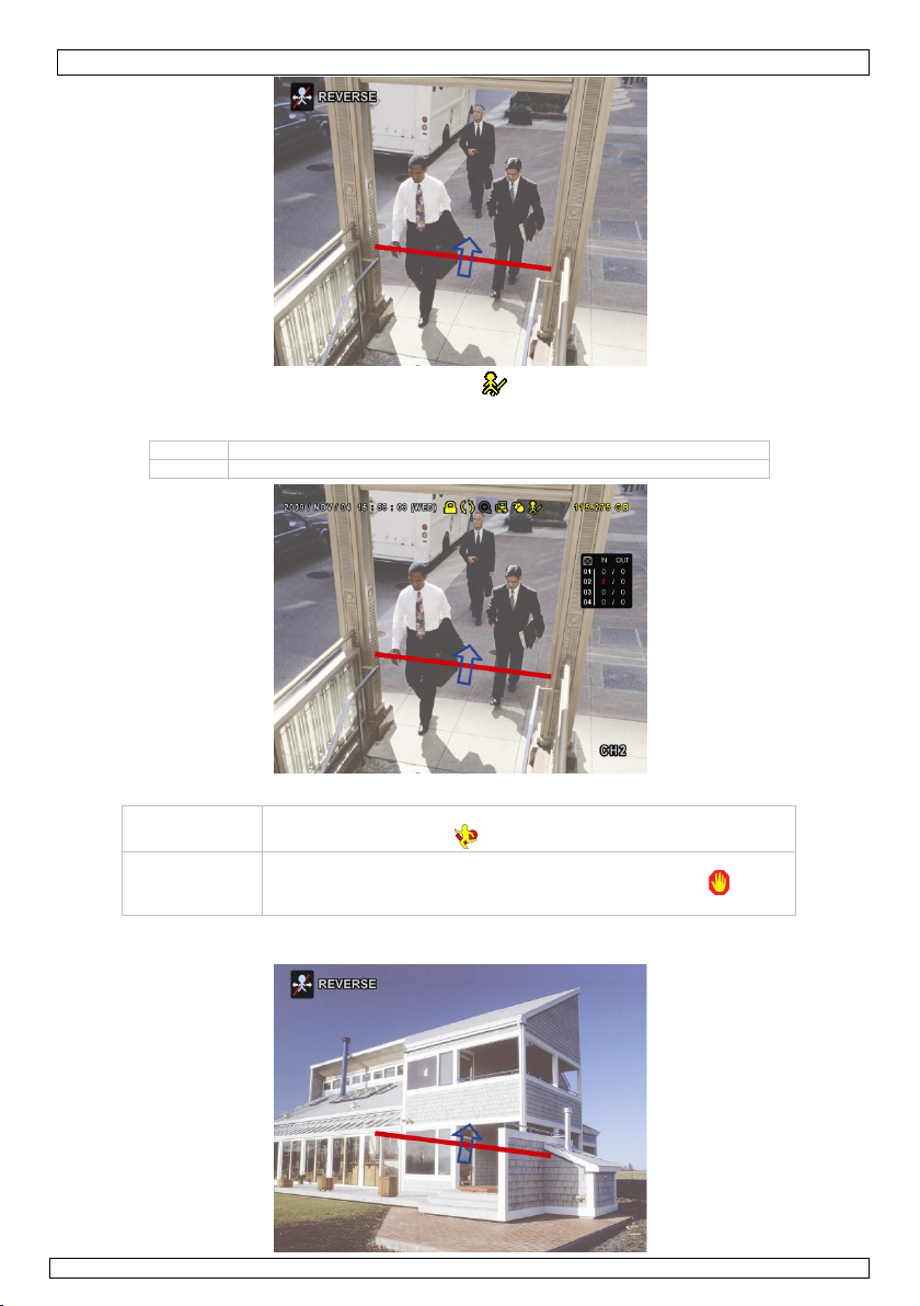
IVSPROM1
• SCHRITT 2: Kehren Sie zur Live-Ansicht zurück. erscheint in der Statusleiste. Klicken Sie dieses
Symbol an, um den folgenden Schirm anzuzeigen.
Überschreitet eine Person die virtuelle Linie, so bestimmt der DVR die Richtung und zählt jede Person.
IN Personen, die aus der dem Pfeil entgegengesetzter Richtung kommen.
OUT Personen, die aus derselben Richtung wie der des Pfeils kommen
10.2 Virtuelle Mauer / Menschenstrom
VIRTUAL FENCE
ONE WAY PASS
• SCHRITT 1: Gehen Sie zu VIRTUAL FENCE AREA um die virtuelle Linie mit der Maus einzustellen.
Stellen Sie die Richtung ein, indem Sie REVERSE auswählen.
09.11.2010 ©Velleman nv
Der Alarm ertönt wenn eine Person die virtuelle Linie überschreitet,
ungeachtet der Richtung. erscheint im Bildschirm.
Der Alarm ertönt wenn eine Person die virtuelle Linie in
entgegengesetzter Richtung wie der des Pfeils überschreitet.
erscheint im Bildschirm.
90
Page 91

• SCHRITT 2: Kehren Sie zur Live-Ansicht zurück.
Der DVR bestimmt die Richtung jeder Person, die die virtuelle Linie überschreitet.
10.3 Statistiken
IVSPROM1
• Klicken Sie auf > um das Suchfenster anzuzeigen. Wählen Sie danach STATISTIC
LIST
QUICK SEARCH CHANNEL
RECORD EVENT TYPE
MOTION
ALARM
TIME ONE WAY PASS
HUMAN DETECTION
IVS MOTION
FULL ALARM
STATISTIC HARD DISK ALL HDD
TIME 2010/MAY/17
STATISTIC SUBMIT
EXIT
• Füllen Sie alle notwendige Daten ein und klicken Sie auf STATISTIC > SUBMIT um alle Ereignisse
anzuzeigen.
o Klicken Sie LIST oder CHART an, für eine Liste oder eine Grafik aller Ereignisse.
o Klicken Sie DAY an, für eine Übersicht pro Tag, Monat oder Jahr.
IVS STATISTIC
LIST CHART
HOUR COUNT
00:00 – 00:59 0
01:00 – 01:59 0
02:00 – 02:59 0
03:00 – 03:59 0
04:00 – 04:59 0
05:00 – 05:59 0
06:00 – 06:59 0
07:00 – 07:59 0
08:00 – 08:59 3
09:00 – 09:59 9
2010/MAY/17 DAY EXIT
;
01 02 03 04
;
INFLOW
OUTFLOW
VIRTUAL FENCE
HUMAN DETECTION
S
T
09.11.2010 ©Velleman nv
91
Page 92

IVSPROM1
r
11. Technische Daten
IVS DVR: (Intelligent Video Security DVR)
Videoformat NTSC/PAL (automatisch)
Videokompression H.264
Video-Eingang 4 Kanäle, komposites Videosignal 1Vpp / 75 Ohm BNC
VideoAusgang
Bilder per
Sekunde
Aufnahme
Aufnahmegeschwindigkeit für jeden Kanal einstellbar
Bildqualität super best - best - high - normal
Speicherung Festplatte SATA x2, kompatibel HDD 1TB (HDD nicht mitgeliefert)
Aufnahmemodus manuell / Timer / Bewegung / Alarm
Multiplex-Betrieb Live-Ansicht, Aufnahme, Wiedergabe, Sicherungskopie und Netz
Audio I/O 4 Eingänge, 1 Ausgang (mono)
Zone für Bewegungserkennung 16 x 12 Triggerpunkte pro Kamera / 4 Kameras
Empfindlichkeit
Bewegungserfassung
Pre-Alarm-Aufnahme 8 MB
Sicherungskopie USB 2.0 und Backup über Netzwerk
Ethernet 10/100 Base-T (unterstützt Fernbedienung und LiveView über Ethernet)
Webschnittstelle unterstützt lizenzierte Software AP / IE und Firefox-Browser
Alarmmeldung Bilder über E-Mail oder FTP-Upload
Netzwerkverbindung unterstützt TCP/IP, PPPoE, DHCP und DDNS
PTZ-Kontrolle PELCO-D
Alarm I/O 4 Eingänge, 1 Ausgang
Digitalzoom 2x
Stromversorgung 19 VDC (mitgeliefert)
Stromverbrauch < 42 W
Betriebstemperatur 10°C ~ 40°C
Systemwiederherstellung
Abmessungen 343 x 59 x 223 mm
PIR-Kamera
Aufnahme-Element 1/3" HR Colour CCD
Pixelanzahl 752(H)x582(V) PAL
Auflösung 480 TV-Zeilen
IR-LEDs 12
minimale Lichtstärke 0.17 lux (F2.0) / 0 lux (IR ein)
Signal-/Rauschabstand > 48 dB (AGC uit)
Objektiv
(Standard)
automatische
Verstärkungsregelung (AGC)
Weißabgleich automatisch
PIR Erfassungsbereich 5 m
Video-Ausgang 1.0Vpp Komposite / 75 Ohm
Stromversorgung 12 VDC
Stromverbrauch 110mA (IR aus), 260mA (IR ein)
Betriebstemperatur 0°C~45°C
Abmessungen 90 x 145 x 32 mm
Gewicht 220 g
zylindrische IR-Farbkamera
Aufnahme-Element 1/3" HR CCD-Farbkamera
Pixelanzahl 512(H) x 582(V) - PAL Auflösung 420 TV-Zeilen
Mindestbeleuchtung 0.05 Lux (F2.0) ; 0 Lux (IR on)
IR-LEDs 21
Bereich (IR-LED) 15m
09.11.2010 ©Velleman nv
Hauptmonito
Call-Monitor komposites Videosignal 1Vpp / 75 Ohm BNC
Bild 704 × 480 Pixel @ 30 Bps (NTSC) / 704 × 576 Pixels @ 25 Bps (PAL)
CIF 352 × 240 Pixel @ 120 Bps (NTSC) / 352 × 288 Pixel @ 100 Bps (PAL)
Brennweite f3.6 mm / f2.0
Blickwinkel 92°
elektronischer
Schutter
Erfassungswinkel 40°
komposites Videosignal 1Vpp / 75 Ohm BNC
4 konfigurierbare Faktoren mit genauer Bewegungserfassung
automatische Systemwiederherstellung nachdem Sie die Stromversorgung
wieder eingeschaltet haben
1/50 tot 1/100 000 Sek.
ja
92
Page 93

IVSPROM1
Signal/Rauschabstand > 48dB (AGC off)
Wasserfestigkeit IP67
elektronischer Verschluss 1/50 bis 1/100000 Sekunden
Blickwinkel 92.6°
Weißabgleich automatisch
automatische
Verstärkungsregelung (AGC) ja
Objektiv f3.6mm / F2.0
Video-Ausgang 1.0Vpp 'composite', 75 Ohm
Stromversorgung DC 12V (verwenden Sie PS1205R, nicht mitgeliefert.)
Stromverbrauch 70mA (IR off), 270mA (IR on)
Arbeitstemperatur 0°C - 45°C
Abmessungen 140 x 56 x 80mm
Gewicht 285g
Verwenden Sie dieses Gerät nur mit originellen Zubehörteilen. Velleman NV übernimmt keine
Haftung für Schaden oder Verletzungen bei (falscher) Anwendung dieses Gerätes.
Für mehr Informationen zu diesem Produkt, siehe www.velleman.eu
Alle Änderungen ohne vorherige Ankündigung vorbehalten.
© URHEBERRECHT
Velleman NV besitzt das Urheberrecht für diese Bedienungsanleitung.
Alle weltweiten Rechte vorbehalten. Ohne vorherige schriftliche Genehmigung des Urhebers ist es nicht gestattet, diese
Bedienungsanleitung ganz oder in Teilen zu reproduzieren, zu kopieren, zu übersetzen, zu bearbeiten oder zu
speichern.
.
09.11.2010 ©Velleman nv
93
Page 94

Velleman® Service and Quality Warranty
Velleman® has over 35 years of experience in the electronics world
and distributes its products in more than 85 countries.
All our products fulfil strict quality requirements and legal stipulations
in the EU. In order to ensure the quality, our products regularly go
through an extra quality check, both by an internal quality department
and by specialized external organisations. If, all precautionary
measures notwithstanding, problems should occur, please make
appeal to our warranty (see guarantee conditions).
General Warranty Conditions Concerning Consumer Products
(for EU):
• All consumer products are subject to a 24-month warranty on
production flaws and defective material as from the original date of
purchase.
• Velleman® can decide to replace an article with an equivalent
article, or to refund the retail value totally or partially when the
complaint is valid and a free repair or replacement of the article is
impossible, or if the expenses are out of proportion.
You will be delivered a replacing article or a refund at the value of
100% of the purchase price in case of a flaw occurred in the first year
after the date of purchase and delivery, or a replacing article at 50%
of the purchase price or a refund at the value of 50% of the retail
value in case of a flaw occurred in the second year after the date of
purchase and delivery.
• Not covered by warranty:
- all direct or indirect damage caused after delivery to the article (e.g.
by oxidation, shocks, falls, dust, dirt, humidity...), and by the article,
as well as its contents (e.g. data loss), compensation for loss of
profits;
- frequently replaced consumable goods, parts or accessories such as
batteries, lamps, rubber parts, drive belts... (unlimited list);
- flaws resulting from fire, water damage, lightning, accident, natural
disaster, etc. …;
- flaws caused deliberately, negligently or resulting from improper
handling, negligent maintenance, abusive use or use contrary to the
manufacturer’s instructions;
- damage caused by a commercial, professional or collective use of the
article (the warranty validity will be reduced to six (6) months when
the article is used professionally);
- damage resulting from an inappropriate packing and shipping of the
article;
- all damage caused by modification, repair or alteration performed by
a third party without written permission by Velleman®.
• Articles to be repaired must be delivered to your Velleman® dealer,
solidly packed (preferably in the original packaging), and be completed
with the original receipt of purchase and a clear flaw description.
• Hint: In order to save on cost and time, please reread the manual
and check if the flaw is caused by obvious causes prior to presenting
the article for repair. Note that returning a non-defective article can
also involve handling costs.
• Repairs occurring after warranty expiration are subject to shipping
costs.
• The above conditions are without prejudice to all commercial
warranties.
The above enumeration is subject to modification according to
the article (see article’s manual).
Velleman® service- en kwaliteitsgarantie
Velleman® heeft ruim 35 jaar ervaring in de elektronicawereld en
verdeelt in meer dan 85 landen.
Al onze producten beantwoorden aan strikte kwaliteitseisen en aan de
wettelijke bepalingen geldig in de EU. Om de kwaliteit te waarborgen,
ondergaan onze producten op regelmatige tijdstippen een extra
kwaliteitscontrole, zowel door onze eigen kwaliteitsafdeling als door
externe gespecialiseerde organisaties. Mocht er ondanks deze
voorzorgen toch een probleem optreden, dan kunt u steeds een
beroep doen op onze waarborg (zie waarborgvoorwaarden).
Algemene waarborgvoorwaarden consumentengoederen (voor
Europese Unie):
• Op alle consumentengoederen geldt een garantieperiode van 24
maanden op productie- en materiaalfouten en dit vanaf de
oorspronkelijke aankoopdatum.
• Indien de klacht gegrond is en een gratis reparatie of vervanging van
een artikel onmogelijk is of indien de kosten hiervoor buiten
verhouding zijn, kan Velleman® beslissen het desbetreffende artikel te
vervangen door een gelijkwaardig artikel of de aankoopsom van het
artikel gedeeltelijk of volledig terug te betalen. In dat geval krijgt u
een vervangend product of terugbetaling ter waarde van 100% van de
aankoopsom bij ontdekking van een gebrek tot één jaar na aankoop
en levering, of een vervangend product tegen 50% van de kostprijs of
terugbetaling van 50 % bij ontdekking na één jaar tot 2 jaar.
• Valt niet onder waarborg:
- alle rechtstreekse of onrechtstreekse schade na de levering
veroorzaakt aan het toestel (bv. door oxidatie, schokken, val, stof,
vuil, vocht...), en door het toestel, alsook zijn inhoud (bv. verlies van
data), vergoeding voor eventuele winstderving.
- verbruiksgoederen, onderdelen of hulpstukken die regelmatig dienen
te worden vervangen, zoals bv. batterijen, lampen, rubberen
onderdelen, aandrijfriemen... (onbeperkte lijst).
- defecten ten gevolge van brand, waterschade, bliksem, ongevallen,
natuurrampen, enz.
- defecten veroorzaakt door opzet, nalatigheid of door een
onoordeelkundige behandeling, slecht onderhoud of abnormaal gebruik
of gebruik van het toestel strijdig met de voorschriften van de
fabrikant.
- schade ten gevolge van een commercieel, professioneel of collectief
gebruik van het apparaat (bij professioneel gebruik wordt de
garantieperiode herleid tot 6 maand).
- schade veroorzaakt door onvoldoende bescherming bij transport van
het apparaat.
- alle schade door wijzigingen, reparaties of modificaties uitgevoerd
door derden zonder toestemming van Velleman®.
• Toestellen dienen ter reparatie aangeboden te worden bij uw
Velleman®-verdeler. Het toestel dient vergezeld te zijn van het
oorspronkelijke aankoopbewijs. Zorg voor een degelijke verpakking
(bij voorkeur de originele verpakking) en voeg een duidelijke
foutomschrijving bij.
• Tip: alvorens het toestel voor reparatie aan te bieden, kijk nog eens
na of er geen voor de hand liggende reden is waarom het toestel niet
naar behoren werkt (zie handleiding). Op deze wijze kunt u kosten en
tijd besparen. Denk eraan dat er ook voor niet-defecte toestellen een
kost voor controle aangerekend kan worden.
• Bij reparaties buiten de waarborgperiode zullen transportkosten
aangerekend worden.
• Elke commerciële garantie laat deze rechten onverminderd.
Bovenstaande opsomming kan eventueel aangepast worden
naargelang de aard van het product (zie handleiding van het
betreffende product).
Garantie de service et de qualité Velleman®
Velleman® jouit d’une expérience de plus de 35 ans dans le monde de
l’électronique avec une distribution dans plus de 85 pays.
Tous nos produits répondent à des exigences de qualité rigoureuses et
à des dispositions légales en vigueur dans l’UE. Afin de garantir la
qualité, nous soumettons régulièrement nos produits à des contrôles
de qualité supplémentaires, tant par notre propre service qualité que
par un service qualité externe. Dans le cas improbable d’un défaut
malgré toutes les précautions, il est possible d’invoquer notre garantie
(voir les conditions de garantie).
Conditions générales concernant la garantie sur les produits
grand public (pour l’UE) :
• tout produit grand public est garanti 24 mois contre tout vice de
production ou de matériaux à dater du jour d’acquisition effective ;
• si la plainte est justifiée et que la réparation ou le remplacement
d’un article est jugé impossible, ou lorsque les coûts s’avèrent
disproportionnés, Velleman® s’autorise à remplacer ledit article par un
article équivalent ou à rembourser la totalité ou une partie du prix
d’achat. Le cas échéant, il vous sera consenti un article de
remplacement ou le remboursement complet du prix d’achat lors d’un
défaut dans un délai de 1 an après l’achat et la livraison, ou un article
de remplacement moyennant 50% du prix d’achat ou le
remboursement de 50% du prix d’achat lors d’un défaut après 1 à 2
ans.
• sont par conséquent exclus :
- tout dommage direct ou indirect survenu à l’article après livraison
(p.ex. dommage lié à l’oxydation, choc, chute, poussière, sable,
impureté…) et provoqué par l’appareil, ainsi que son contenu (p.ex.
perte de données) et une indemnisation éventuelle pour perte de
revenus ;
- tout bien de consommation ou accessoire, ou pièce qui nécessite un
remplacement régulier comme p.ex. piles, ampoules, pièces en
caoutchouc, courroies… (liste illimitée) ;
- tout dommage qui résulte d’un incendie, de la foudre, d’un accident,
d’une catastrophe naturelle, etc. ;
- out dommage provoqué par une négligence, volontaire ou non, une
utilisation ou un entretien incorrects, ou une utilisation de l’appareil
contraire aux prescriptions du fabricant ;
- tout dommage à cause d’une utilisation commerciale, professionnelle
ou collective de l’appareil (la période de garantie sera réduite à 6 mois
lors d’une utilisation professionnelle) ;
- tout dommage à l’appareil qui résulte d’une utilisation incorrecte ou
différente que celle pour laquelle il a été initialement prévu comme
décrit dans la notice ;
- tout dommage engendré par un retour de l’appareil emballé dans un
conditionnement non ou insuffisamment protégé.
- toute réparation ou modification effectuée par une tierce personne
sans l’autorisation explicite de SA Velleman® ; - frais de transport de
et vers Velleman® si l’appareil n’est plus couvert sous la garantie.
Page 95

• toute réparation sera fournie par l’endroit de l’achat. L’appareil doit
nécessairement être accompagné du bon d’achat d’origine et être
dûment conditionné (de préférence dans l’emballage d’origine avec
mention du défaut) ;
• tuyau : il est conseillé de consulter la notice et de contrôler câbles,
piles, etc. avant de retourner l’appareil. Un appareil retourné jugé
défectueux qui s’avère en bon état de marche pourra faire l’objet
d’une note de frais à charge du consommateur ;
• une réparation effectuée en-dehors de la période de garantie fera
l’objet de frais de transport ;
• toute garantie commerciale ne porte pas atteinte aux conditions
susmentionnées.
La liste susmentionnée peut être sujette à une
complémentation selon le type de l’article et être mentionnée
dans la notice d’emploi.
Garantía de servicio y calidad Velleman®
Velleman® disfruta de una experiencia de más de 35 años en el
mundo de la electrónica con una distribución en más de 85 países.
Todos nuestros productos responden a normas de calidad rigurosas y
disposiciones legales vigentes en la UE. Para garantizar la calidad,
sometimos nuestros productos regularmente a controles de calidad
adicionales, tanto por nuestro propio servicio de calidad como por un
servicio de calidad externo. En el caso improbable de que surgieran
problemas a pesar de todas las precauciones, es posible apelar a
nuestra garantía (véase las condiciones de garantía).
Condiciones generales referentes a la garantía sobre productos
de venta al público (para la Unión Europea):
• Todos los productos de venta al público tienen un período de
garantía de 24 meses contra errores de producción o errores en
materiales desde la adquisición original;
• Si la queja está fundada y si la reparación o la sustitución de un
artículo es imposible, o si los gastos son desproporcionados,
Velleman® autoriza reemplazar el artículo por un artículo equivalente
o reembolsar la totalidad o una parte del precio de compra. En este
caso, recibirá un artículo de recambio o el reembolso completo del
precio de compra al descubrir un defecto hasta un año después de la
compra y la entrega, o un artículo de recambio al 50% del precio de
compra o la sustitución de un 50% del precio de compra al descubrir
un defecto después de 1 a 2 años.
• Por consiguiente, están excluidos entre otras cosas:
- todos los daños causados directamente o indirectamente al aparato y
su contenido después de la entrega (p.ej. por oxidación, choques,
caída,...) y causados por el aparato, al igual que el contenido (p.ej.
pérdida de datos) y una indemnización eventual para falta de
ganancias;
- partes o accesorios que deban ser reemplazados regularmente, como
por ejemplo baterías, lámparas, partes de goma, ... (lista ilimitada)
- defectos causados por un incendio, daños causados por el agua,
rayos, accidentes, catástrofes naturales, etc. ;
- defectos causados a conciencia , descuido o por malos tratos, un
mantenimiento inapropiado o un uso anormal del aparato contrario a
las instrucciones del fabricante;
- daños causados por un uso comercial, profesional o colectivo del
aparato (el período de garantía se reducirá a 6 meses con uso
profesional) ;
- daños causados por un uso incorrecto o un uso ajeno al que est está
previsto el producto inicialmente como está descrito en el manual del
usuario ;
- daños causados por una protección insuficiente al transportar el
aparato.
- daños causados por reparaciones o modificaciones efectuadas por
una tercera persona sin la autorización explicita de SA Velleman® ;
- se calcula gastos de transporte de y a Velleman® si el aparato ya no
está cubierto por la garantía.
• Cualquier reparación se efectuará por el lugar de compra. Devuelva
el aparato con la factura de compra original y transpórtelo en un
embalaje sólido (preferentemente el embalaje original). Incluya
también una buena descripción del defecto ;
• Consejo: Lea el manual del usuario y controle los cables, las pilas,
etc. antes de devolver el aparato. Si no se encuentra un defecto en el
artículo los gastos podrían correr a cargo del cliente;
• Los gastos de transporte correrán a carga del cliente para una
reparación efectuada fuera del periode de garantía.
• Cualquier gesto comercial no disminuye estos derechos.
La lista previamente mencionada puede ser adaptada según el
tipo de artículo (véase el manual del usuario del artículo en
cuestión)
Velleman® Service- und Qualitätsgarantie
Velleman® hat gut 35 Jahre Erfahrung in der Elektronikwelt und
vertreibt seine Produkte in über 85 Ländern.
Alle Produkte entsprechen den strengen Qualitätsforderungen und
gesetzlichen Anforderungen in der EU. Um die Qualität zu
gewährleisten werden unsere Produkte regelmäßig einer zusätzlichen
Qualitätskontrolle unterworfen, sowohl von unserer eigenen
Qualitätsabteilung als auch von externen spezialisierten
Organisationen. Sollten, trotz aller Vorsichtsmaßnahmen, Probleme
auftreten, nehmen Sie bitte die Garantie in Anspruch (siehe
Garantiebedingungen).
Allgemeine Garantiebedingungen in Bezug auf Konsumgüter
(für die Europäische Union):
• Alle Produkte haben für Material- oder Herstellungsfehler eine
Garantieperiode von 24 Monaten ab Verkaufsdatum.
• Wenn die Klage berechtigt ist und falls eine kostenlose Reparatur
oder ein Austausch des Gerätes unmöglicht ist, oder wenn die Kosten
dafür unverhältnismäßig sind, kann Velleman® sich darüber
entscheiden, dieses Produkt durch ein gleiches Produkt zu ersetzen
oder die Kaufsumme ganz oder teilweise zurückzuzahlen. In diesem
Fall erhalten Sie ein Ersatzprodukt oder eine Rückzahlung im Werte
von 100% der Kaufsumme im Falle eines Defektes bis zu 1 Jahr nach
Kauf oder Lieferung, oder Sie bekommen ein Ersatzprodukt im Werte
von 50% der Kaufsumme oder eine Rückzahlung im Werte von 50 %
im Falle eines Defektes i m zweiten Jahr.
• Von der Garantie ausgeschlossen sind:
- alle direkten oder indirekten Schäden, die nach Lieferung am Gerät
und durch das Gerät verursacht werden (z.B. Oxidation, Stöße, Fall,
Staub, Schmutz, Feuchtigkeit, ...), sowie auch der Inhalt (z.B.
Datenverlust), Entschädigung für eventuellen Gewinnausfall.
- Verbrauchsgüter, Teile oder Zubehörteile, die regelmäßig
ausgewechselt werden, wie z.B. Batterien, Lampen, Gummiteile,
Treibriemen, usw. (unbeschränkte Liste).
- Schäden verursacht durch Brandschaden, Wasserschaden, Blitz,
Unfälle, Naturkatastrophen, usw.
- Schäden verursacht durch absichtliche, nachlässige oder
unsachgemäße Anwendung, schlechte Wartung, zweckentfremdete
Anwendung oder Nichtbeachtung von Benutzerhinweisen in der
Bedienungsanleitung.
- Schäden infolge einer kommerziellen, professionellen oder
kollektiven Anwendung des Gerätes (bei gewerblicher Anwendung wird
die Garantieperiode auf 6 Monate zurückgeführt).
- Schäden verursacht durch eine unsachgemäße Verpackung und
unsachgemäßen Transport des Gerätes.
- alle Schäden verursacht durch unautorisierte Änderungen,
Reparaturen oder Modifikationen, die von einem Dritten ohne Erlaubnis
von Velleman® vorgenommen werden.
• Im Fall einer Reparatur, wenden Sie sich an Ihren Velleman®Verteiler. Legen Sie das Produkt ordnungsgemäß verpackt
(vorzugsweise die Originalverpackung) und mit dem OriginalKaufbeleg vor. Fügen Sie eine deutliche Fehlerumschreibung hinzu.
• Hinweis: Um Kosten und Zeit zu sparen, lesen Sie die
Bedienungsanleitung nochmals und überprüfen Sie, ob es keinen auf
de Hand liegenden Grund gibt, ehe Sie das Gerät zur Reparatur
zurückschicken. Stellt sich bei der Überprüfung des Geräts heraus,
dass kein Geräteschaden vorliegt, könnte dem Kunden eine
Untersuchungspauschale berechnet.
• Für Reparaturen nach Ablauf der Garantiefrist werden
Transportkosten berechnet.
• Jede kommerzielle Garantie lässt diese Rechte unberührt.
Die oben stehende Aufzählung kann eventuell angepasst
werden gemäß der Art des Produktes (siehe
Bedienungsanleitung des Gerätes).
 Loading...