

Page 1
CS990
Professional metal detector
Operating manual
Gebruikers handleiding
Manuel de l’Utilisation
Page 2

CS-990 OPERATING INSTRUCTIONS
INTRODUCTION
These metal detectors are recognised as the finest detectors available. They are designed with lasting
quality, high technology input, and above all, value for money in mind.
The only way to realise this value and quality is to carefully study and understand this instruction
manual. You will then be able to make use of all of the advantages designed into your detector. It is
also strongly recommended that you experiment with the detector’s operations indoors in air, with
various test samples, in order to learn to identify and understand the detector’s capabilities and
responses. It is best to lay the detector on a table with the search head off the end and to pass test
objects across the search head to best stimulate actual responses.
FEATURES
Before proceeding to the controls and the operating procedure it is important to understand the
principles of operation of the CS-990.
The CS-990’s principle features are :
Audio Ground Exclusion : Elimination of ground effect.
Meter Discrimination : Rejection of iron and small pieces of silver paper via
the signal meter.
Meter and Sound Discrimination : Rejection of iron and small pieces of silver paper via
the signal meter and loudspeaker and/or headphones.
GROUND EXCLUSION
What is ground exclusion ?
On some sites mineralisation caused by iron deposits or iron oxides or wet salt sand makes it
difficult to operate a detector successfully. The effect of these minerals is termed "GROUND
EFFECT". In practice, the signal of the detector alters if the search head is not kept exactly steady
during sweeping or the gap between the search head and ground varies. If the tuning level increases
upwards, as on inland sites when the detector head is inadvertently raised, the signal may be
confused with a target signal.
The CS-990 offers two modes of ground exclusion :
- A preset ground exclude setting for use on mineralised inland sites, G I.
- A variable ground exclude setting for use on wet salt sand beaches, or for total iron
rejection on non-mineralised inland sites, G II.
CS-990 GB
1
Page 3

Inland Mineralised Sites :
The G 1 mode is the mode in which "Ground Exclusion" is achieved on the majority of inland sites.
Beach and Non-Mineralised Inland Sites :
The G 2 mode enables the detector user to ground exclude on wet salt sand beaches by using the
variable ground exclude control knob identified as "LEVEL", positioned directly above the ground
exclude control knob G 1 & G 1. The G 2 mode also enables the operator to use the detector for
total iron rejection on non-mineralised inland sites.
DISCRIMINATION (Rejection)
What is discrimination ?
It is an obvious advantage when metal detecting to get different signals for worthwhile as opposed
to worthless objects, and therefore be able to discriminate or differentiate in various ways. Basically
a rejected item will cause the signal to fall. The meter needle will drop to the left, and the sound
level will die away and/or decrease in frequency. On the other hand, a good target object will cause
the signal to rise. The meter needle will move to the right and the sound level and frequency will
increase.
The full discrimination facilities of this detector will be described in more detail under the heading
"OPERATING THE DETECTOR IN THE FIELD".
If an object is very close to the search head, conflicting signals may occur. These signals are
characterised by hard swings of the meter needle from left to right. If you encounter such problems
you should raise the search head a few inches (10 cm), retune and rescan. You should now receive a
clear signal.
These anomaly signals are caused by the object overloading the signal. Normally iron fragments or
wire on the surface cause this phenomenon.
CS-990 GB
2
Page 4
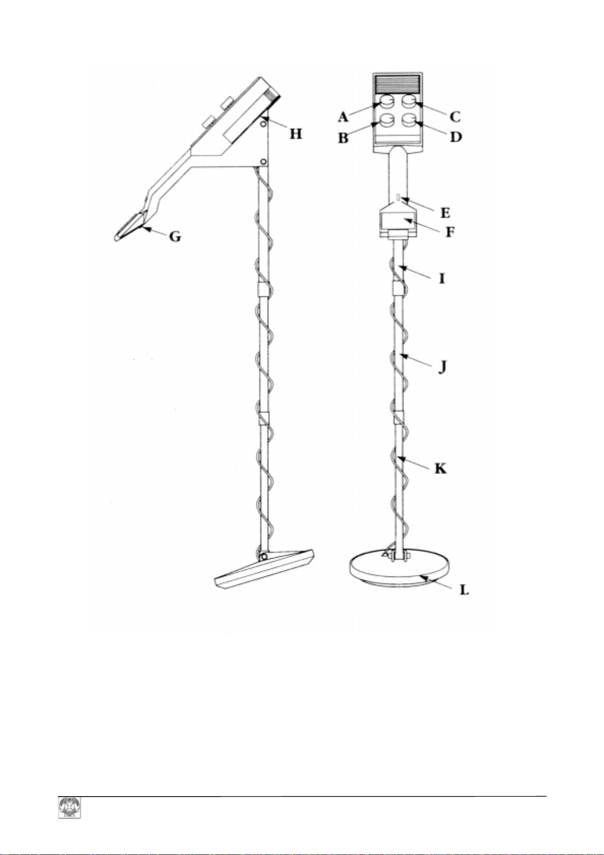
Diagram 1
A ON/OFF Tune Control
B SIMDISC Control
C GROUND EXCLUDE Control
D LEVEL Control
E AUTO-TUNE Button
F METER
G BATTERY CHECK Button
H BATTERY COMPARTMENT
I UPPER STEM
J MIDDLE STEM
K LOWER STEM
L SEARCH HEAD
CS-990 GB
3
Page 5

B
D
ASSEMBLY
How to assemble your CS-990.
Your CS-990 comes to you dismantled for ease of packing. To assemble it, follow these few easy
steps :
1. Locate the stems in the special compartment in the packaging.
2. Loosen and remove the two screws and nuts from the base of the control box.
3. Insert upper stem 1 into the aperture at the base of the case and replace the two screws and
nuts and tighten.
4. Loosen and remove the knurled nut from the upper stem, slide it over middle stem J, insert the
middle stem into the upper stem, align the knurled nut and fasten it.
5. Attach lower stem K to the search head L with the nut and screw provided.
6. Loosen and remove the knurled nut from the middle stem, slide it over the lower stem, insert
the lower stem into the middle stem, align the knurled nut and fasten it loosely. Then twist the
lower stem and search head in a clockwise direction until the cable is loosely wound around
the whole stem assembly.
Ensure that the cable is not wound too tightly and that there is sufficient slack at the search
head end to avoid cable breakage should the head be removed in relation to the stem. Now
firmly tighten the knurled nut of the lower stem. Your detector is now ready for use, except
for the power supply.
BATTERIES
Now that you have assembled your CS-990, all that is required before you use it is the power
supply.
Your CS-990 is powered by 5 Type PP3
batteries.
Please note : It is advisable to use batteries
manufactured by a well-known
manufacturer as 80% of faults occurring
with metal detectors can be traced to faulty
or badly connected batteries.
To fit batteries proceed as follows :
1. Apply gentle pressure on the ribbed
part of the battery cover and push the
cover forwards (towards the meter).
2. Locate the battery leads and connect
the batteries ensuring that they are
connected correctly (polarity) and
firmly.
iagram 2
Please note that the second
battery compartment is on the
other side of the control box.
attery
Compartment
CS-990 GB
4
Page 6

3. Place the batteries and leads into the special recess, replace the battery cover and slide it
firmly into place until you hear it click into position.
4. Repeat this operation on the other side of the control box where the second battery
compartment is located.
Battery life will be extended if headphones are used. The headphone socket is located on the lefthand side of the control box, on its underside. In the event that the detector is not being used for a
long period of time (over 2 months) or stored, it is strongly recommended that the batteries should
be removed from the detector, thus avoiding possible leakage and expensive repairs.
CONTROLS AND WHAT THEY DO
A. ON/OFF TUNE CONTROL
This control turns the detector on and off and sets the tuning level. It must be used in conjunction
with the Auto-Tune Button E.
To tune the detector to the optimum level, press and hold the Auto-Tune button, then switch on the
detector and turn the tune button in a clockwise direction until a faint sound can be heard and the
meter needle is in the TUNE section of the signal meter. Only then should the Auto-Tune button be
released. Any tune setting above or below this optimum level will reduce the sensitivity of the
detector. When using the detector in the field it is advisable to release the Auto-Tune button only
when the search head has been lowered to its operational or search height - i.e. ½" - 1" (1 to 3 cm)
above ground level.
B. SIMDISC CONTROL
This control enables the user to select the mode of operation desired :
- OFF - In this position the detector will give a positive signal to all metals, both via the
sound and meter channel, providing that the ground exclude switch is in the G 1 setting.
- METER - In this position the detector will ground exclude via the sound channel, whilst
simultaneously rejecting iron and small pieces of silver paper via the meter channel.
- METER & AUDIO - In this position the detector will still ground exclude, but also
identify the nature of the find in the following manner:
a) A negative signal against iron on the signal meter, and a possible unchanged needle
position for small pieces of silver paper.
b) An increase in sound level, however the frequency will decrease for iron, and an
increase in sound level with a possible slight frequency change for small pieces of
silver paper.
CS-990 GB
5
Page 7

C. GROUND EXCLUDE CONTROL
This control enables the user to select a mode of operation best suited to the site to be worked on,
for instance:
G 1 is the mode to be used on mineralised inland sites and can be used in conjunction with any of
the Simdisc modes described above depending on the nature of finds the user wishes to locate or
reject. With this setting the level of ground exclusion is pre-set.
G 2 is the mode best suited to beaches, but it can also be used on non-mineralised inland sites when
ground effect is not particularly serious but the rejection of iron is specifically desired. In this
setting, the user can finely adjust the level of ground exclusion required for wet salt sand by using
the "LEVEL" Control D.
D. LEVELCONTROL
This control is used in conjunction with the G 2 mode and acts as a variable ground exclusion
control to allow the user to accurately set the level of ground exclusion required on particular beach
sites, or allows adjustment to the rejection level against iron and small pieces of silver paper.
E. AUTO-TUNE BUTTON
The Auto-tune button is the control on the detector which is most frequently used. It must be
pressed and held whenever an alteration is made to any one of the four other controls and should
only be released once such alterations have been completed. It also acts as a memory retune button
and will, when pressed, recall the optimum tuning level should the detector drift out of tune due to
temperature changes, search head to ground level changes or when false signals are received. Please
note that the Auto-Tune button should only be released after initial tuning, mode changes etc. once
the search head has been lowered to the operational search height. Searching should always take
place with the Auto-Tune button released.
F. METER
1 . The meter will give a visual indication of the optimum tuning level when the needle is in the
central TUNE position.
2. When using the detector in the meter discriminate mode, it will show a negative response to
unwanted items (needle will swing to the left from its central position).
3. When pinpointing a target signal, full deflection of the meter needle to the right will indicate
that the object is situated under the centre of the search head.
4. The meter acts as a battery check - See G.
CS-990 GB
6
Page 8

G. BATTERY CHECK
Battery check Button G is provided as a guide to the battery’s condition. To check the battery
condition, switch on the detector by turning the On/Off switch in a clockwise direction whilst
simultaneously pressing the auto-tune button, once the detector is tuned, release the Auto-Tune
button and then press button G situated under the meter. If the needle on the meter swings into the
bold red sector the batteries are in good condition. Should the needle not reach this sector of the
meter and remain, the batteries will need to be renewed. The use of headphones is recommended as
these not only offer longer battery life but also ensure that the user will hear the slightest signal
change, which could indicate a valuable find which otherwise could be missed.
H. BATTERY COMPARTMENTS
There are two battery compartments on the 990 and these are situated on the left and right hand
sides of the detector control box and are covered by easily-opened covers.
I, J, & K. STEMS
These are assembled by fitting the upper stem to the main body of the detector in the aperture
provided and by inserting the middle and lower stem into one another. A knurled nut containing a
plastic olive effects the tightening. It is recommended that the knurled nut is removed from the base
of the stem, placed over the thinner of the stems of any two being connected together before sliding
this stem into the thicker one. The knurled nut can then be offered up to the thread on the thicker
stem and tightened.
L. SEARCH HEAD
The concentric coil arrangement of the search head is designed to transmit and receive a magnetic
field and detect the changes that occur when metal is present. Because the receive coil is in the
centre and the transmit coil around the perimeter, the hot-spot or pinpointing area is in the exact
centre of the search head.
The metal detector’s search heads are fully waterproof and can therefore be immersed in rivers,
rockpools etc. up to the lowest knurled nut. After use, particularly in salt water, it is advisable to
wash off the search head and the lower stem into fresh water, carefully wiping it dry with a soft
cloth. It must be remembered that the search head is very sensitive to temperature changes. It is
therefore important to allow the detector to reach the temperature of the surroundings in which it
will be used. For example, if you take the detector from a hot car on a cold day, the detector signal
will drift and be unstable until the head has absorbed the temperature change.
CS-990 GB
7
Page 9

OPERATING PROCEDURE
The fundamental principle of detector operation is that the detector must be tuned to the correct
level. This is the level when the signals are balanced, and this is indicated by the detector being
neither silent nor sounding off. In fact, the correct tuning level is the threshold setting when the
sound is just beginning to break through.
For best results, it is important to set this tuning level accurately and to maintain it at all times when
searching.
Follow this procedure:
1. Set the detector to the desired ground exclude position G 1 or G 2.
2. Set the Simdisc control to the desired mode of operation: Off, meter discrimination or meter
and audio discrimination.
3. Press and hold auto-tune button, turn on the detector by rotating the On/Off tuning control
until a faint sound is heard. Lower the search head to the operational/searching height and
only then release the auto-tune button. You are now ready to commence searching. Should the
tuning level alter for any reason simply retune the detector by pressing the auto-tune button.
OPERATING THE DETECTOR IN THE FIELD
What now follows is a brief guide on how to obtain the best results from your newly-acquired
detector and how to recognise the signals given by the detector.
1. On inland sites select G 1.
2. On a beach with wet, salt sand select G 2.
Having selected the main mode of operation, G 1 or G 2, you can now decide which mode of
discrimination you wish to operate in:
a) - G 1, Simdisc OFF
In this setting, the detector will give a positive signal to all metals. The meter needle swings to the
right and the sound becomes louder.
b) - G 1, Simdisc Meter
In this setting, the detector will give a negative meter reading to iron, however the sound will
become louder. The signal received from a small piece of silver paper will be an increase in volume
loudness and a slight negative or unnoticeable meter change. Larger pieces of silver paper and all
other metals will give a positive signal both on the signal and meter channel. The meter needle
swings to the right and the sound increases in volume.
c) - G 1, Simdisc Meter and Audio
In this setting, the signals given by the detector for iron are a negative indication by the meter,
increase in volume combined with a reduction in frequency.
CS-990 GB
8
Page 10

Small pieces of silver paper are indicated by an increase in volume, however the frequency may not
alter and the meter needle will remain in the centre or move just slightly to the left.
Larger pieces of silver paper and other metallic objects will be indicated by a meter needle swing to
the right, an increase in volume combined with an increase in frequency.
d) - G 2 Simdisc OFF
In this setting, the detector will give a negative meter reading for iron, the meter needle will swing
to the left and the sound disappears. All other metals, however, will give a positive signal both on
the sound and meter channel.
e) - G 2 Simdisc Meter
In this setting, the detector will give a negative meter reading for iron and the sound disappears. The
signals produced by small pieces of silver paper are that the sound and meter indication may not
alter.
Larger pieces of silver paper and other metals will be signalled by an increase in volume and a
meter needle deflection to the right.
f) - G 2 Simdisc Meter and Audio
In this setting, the signals given by the detector for iron are a negative indication on the meter and a
disappearing sound.
Small pieces of silver paper may be indicated by a slight change in meter reading and/or sound level
and frequency.
All other objects will be signalled by a meter deflection to the right and an increase in volume and
frequency.
PLEASE NOTE
Although the level control primarily acts as a variable ground exclude control when used in
conjunction with the G 2 mode, it can, if set above or below the central position, slightly affect the
discrimination capability of the detector for small pieces of silver paper both in the G 1 or G 2
modes of operation. The above described signals should therefore only be seen as broad guidelines.
IT IS THEREFORE RECOMMENDED THAT BEFORE YOU USE THE DETECTOR
OUTDOORS, YOU EXPERIMENT INDOORS WITH VARIOUS TEST SAMPLES AND
NOTE THE SIGNALS GENERATED.
CS-990 GB
9
Page 11

USE IN THE FIELD
a
Detection Area
These detectors employ a Total Response
search
head which means that the object can be
detected across the full width of the search
head.
Diagram 3
Detection Range
Detection ranges will vary depending on the size of the object, the length of time an object has been
buried, and the type of ground the object is buried in. The best ground conditions are dry, wellcompacted soils ; then coins can be found at the greatest depths if they have been buried for some
time and the coin has interacted with the salts in the ground, thereby appearing larger to the
detector. The worst conditions for detecting are on loosely compacted or freshly dug ground or
when the object has only recently been buried. In these conditions detection range will be reduced.
90% of all objects are found within 6" (20 cm) of the surface. Adverse soil conditions can reduce
the depth of detection by more than half.
Search Are
Determining the Target Size and Depth
An operator who is familiar with his instrument will be able to do an excellent job of determining
object size, shape and depth before he digs. The technique is learned from careful analysis of the
audio signals coming from the detector. Each time a signal is heard, listen for any peculiar
characteristics it may have; determine over how large an area you get a detector signal, and try to
’outline’ the object before you dig. Listen for the sharpness or dullness of the signals and determine
the magnitude of strength of the signal. A coin will have a sharp signal, a nail a fuzzy signal.
CARE AND MAINTENANCE
Care of Your Detector
The working life of your detector will be shortened by careless use or neglect of the unit. Think of
your detector as a scientific instrument, NOT A TOY. Your detector is designed to withstand
rugged handling on any terrain, but mis-use or lack of due attention will tell in the end.
After using your detector in a hostile environment (salt water, sand etc.) the exterior parts of the
casing should be wiped with a damp cloth, paying particular attention to the head, and carefully
wiped dry. Foreign particles in the control box can be removed by brushing carefully (or with
compressed air or a vacuum cleaner).
CS-990 GB
10
Page 12

Salt Damage
If you use your detector continually in a salty environment, particularly when the wind is blowing
off the sea, salty air can penetrate the control box.
Corrosion can occur in vital parts of the delicate electronic circuitry.
It is therefore recommended that precautions such as covering the control box with polythene be
taken to avoid damage.
The guarantee cannot cover such occurrences and any repairs needed because of salt water or spray
will be charged.
Use of Solvents
It has been found that some types of solvent used for cleaning circuitry will in fact melt the plasticcovered components.
The life of the controls may be extended by periodic (every 100 hours of use) application of small
quantities of light lubricant to the spindles, threads and knob grub screw (’3 in 1’ or similar
household oil is suitable). This operation requires the knobs to be removed.
Light packing grease should be smeared on the threads of the locking collar and, at the same time,
the head fixing bolt. Do not store the detector in a damp place.
If the detector is to be stored, remove the batteries as they may leak and corrode the surrounding
electronics.
Detector Not Operating
(A) Check the condition of the batteries.
(B) Change the batteries and ensure the connections are correct and secure.
Battery life can vary tremendously between makes, therefore your ’new’ batteries may already
be insufficiently powerful to run your detector.
(C) Check that the search head cable connector is properly attached to the control box.
Oscillating Signal Accompanied by Slight Meter Fluctuation
(A) This is caused most often by outside equipment such as fluorescent lights, taxis, radios, power
lines and other metal detectors working nearby. Little can be done to alleviate the problem
except to find a new site.
Intermittent Sound From Speaker
(A) This could be due to poor battery connections. Ensure they are tight and the batteries are
securely clipped into place.
(B) Radio transmission from a passing taxi or vehicle using radio transmitter equipment.
CS-990 GB
11
Page 13

The Detector Drifts out of Tune
(A) Temperature drift caused by the change in air temperature when a machine is moved from a
house or a car into the open.
(B) The greater the change in temperat ure the more the dri ft, and up to 30 minutes may be needed
for the electronic circuitry to acclimatise itself.
(C) Sometimes battery drain can cause the signal to drift. Replace batteries and this should help to
maintain a stable signal.
Before returning a detector for repair, ensure you have done the following :
(A) Read the instructions thoroughly.
(B) Tried new batteries and checked the procedure outlined above.
(C) Spoken to the local dealer about performance of the detector, especially if you are still
unfamiliar with metal detectors in general.
Return the detector with a letter giving details of the error.
CS-990 GB
12
 Loading...