

Page 1

CAMSET27
BUILD-IN BACKING CAMERA WITH COLOUR DISPLAY
ACHTERUITRIJDCAMERA MET KLEURENDISPLAY
CAMÉRA DE RECUL AVEC AFFICHEUR COULEUR
CÁMARA DE APARCAMIENTO CON PANTALLA A COLOR
RÜCKFAHRKAMERA MIT FARBDISPLAY
USER MANUAL 3
GEBRUIKERSHANDLEIDING 5
NOTICE D’EMPLOI 8
MANUAL DEL USUARIO 10
BEDIENUNGSANLEITUNG 13
Page 2
CAMSET27
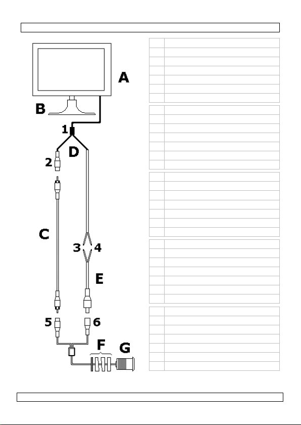
A display
B mounting bracket
C video cable
D monitor cable
E power cable
F adjustment rings
G camera
A display
B montagebeugel
C videokabel
D displaykabel
E voedingskabel
F tussenringen
G camera
A afficheur
B étrier
C câble vidéo
D câble de l’afficheur
E câble d’alimentation
F entretoises
G caméra
A pantalla
B soporte de montaje
C cable de vídeo
D cable de pantalla
E cable de alimentación
F separadores
G cámara
A Display
B Montagebügel
C Videokabel
D Displaykabel
E Netzkabel
F Abstandshalter
G Kamera
Figure 1
29/09/2010 ©Velleman nv
2
Page 3
CAMSET27
User manual
1. Introduction
To all residents of the European Union
Important environmental information about this product
If in doubt, contact your local waste disposal authorities.
Thank you for choosing Velleman! Please read the manual thoroughly before
bringing this device into service. If the device was damaged in transit, don't install
or use it and contact your dealer.
2. Safety Instructions
3. General Guidelines
Refer to the Velleman® Service and Quality Warranty on the last pages of this
manual.
• Familiarise yourself with the functions of the device before actually using it.
• All modifications of the device are forbidden for safety reasons.
• Only use the device for its intended purpose. Using the device in an
• Damage caused by disregard of certain guidelines in this manual is not covered
4. Features
• compact 3.5” high-resolution TFT screen
• camera with IR LEDs
29/09/2010 ©Velleman nv
This symbol on the device or the package indicates that disposal of the
device after its lifecycle could harm the environment. Do not dispose of
the unit (or batteries) as unsorted municipal waste; it should be taken to
a specialized company for recycling.
This device should be returned to your distributor or to a local recycling
service. Respect the local environmental rules.
Keep this device away from children and unauthorized users.
Keep the monitor away from rain, moisture, splashing and dripping
liquids. Protect the device against extreme heat and dust.
Protect this device from shocks and abuse. Avoid brute force when
operating the device.
Risk of electroshock during installation.
The installation must be performed by a qualified technician.
DO NOT disassemble or open the cover(s). No user-serviceable parts
inside. Refer to an authorized dealer for service and/or spare parts.
DO NOT solely rely on the information from the backing system when
driving backwards. Always be aware of the surroundings of the vehicle
before and during use of the system.
unauthorised way will void the warranty.
by the warranty and the dealer will not accept responsibility for any ensuing
defects or problems.
3
Page 4
CAMSET27
5. Installation
Refer to the illustrations on page 2 of this manual.
• Make sure the vehicles’ engine is off and power is removed from the electrical
system. Disconnect the battery and remove the ignition key from the ignition
switch.
• Mount the LCD [A] with the mounting bracket [B] on the dashboard using the
double sided tape on the bottom of the bracket. Make sure the driver has a
clear view on the monitor.
• Connect the monitor cable [D] to the monitor. The connector fits in only one
way, do not force.
• Guide the video cable [C] to the back of the car where the camera will be
mounted.
• Drill a hole (Ø28mm) in the bumper (drill not included).
• Insert the cables [5, 6] and the camera [G] into the hole. Depending on the
location of the camera, use the adjustment rings to level the camera with the
surface of the bumper. Use the nut to secure the camera. Do not tighten it yet.
• Connect the video cable [C] to the camera [5, yellow]; connect the other end
to the monitor cable [D2, yellow].
• Connect the red wire [3] of the monitor cable [D] to the cars +12V electrical
circuit, at a location where there is only power once the ignition key is turned
(run circuit).
• Connect the black wire [4] of the monitor cable [D] to ground (GND).
• Connect the red wire [3] of power cable [E] to the reverse light circuit (+12V).
• Connect the black wire [4] of power cable [E] to ground (GND).
• Connect the other end of power cable [E] to the camera [6, black].
• Restore power to the vehicles’ electrical system; insert the ignition key in the
ignition switch and turn.
• The monitor will now show the image of the camera. Verify that this image is
upright. If not rotate the camera until it is, than secure it by tightening the nut
[F].
6. Technical specifications
system NTSC
monitor size 3.5" TFT
camera pick-up element 1/4" colour CMOS
video input signal 1.0Vpp composite video signal at 75 ohm
A/V input connections RCA connector
power supply DC 12V ±1.5V
29/09/2010 ©Velleman nv
number of pixels 480(H) x 320(V)
video inputs 1
synchronization internal
video output mirror image
horizontal resolution 420 TV-lines
IR LEDs 9
min. illumination 0 Lux when IR on
lens angle 120°
S/N ratio >= 48dB
4
Page 5
CAMSET27
max. current 300mA
cable 1x monitor cable (±2m), 1x power cable
operating temperature -20°C ~ +60°C
dimensions monitor 93 x 102 x 45mm
weight monitor ±120g
Use this device with original accessories only. Velleman nv cannot be held
responsible in the event of damage or injury resulted from (incorrect) use
of this device.
For more info concerning this product and the latest version of this user
manual, please visit our website www.velleman.eu.
The information in this manual is subject to change without prior notice.
© COPYRIGHT NOTICE
This manual is copyrighted. The copyright to this manual is owned by Velleman nv. All
worldwide rights reserved. No part of this manual may be copied, reproduced, translated or
reduced to any electronic medium or otherwise without the prior written consent of the copyright
holder.
camera 31 x 31 x 35mm
camera ±60g
(±1.5m), 1x video cable (±6m), 1x camera
cable (±1.5m)
GEBRUIKERSHANDLEIDING
1. Inleiding
Aan alle ingezetenen van de Europese Unie
Belangrijke milieu-informatie betreffende dit product
milieuwetgeving.
Hebt u vragen, contacteer dan de plaatselijke autoriteiten betreffende de
verwijdering.
Dank u voor uw aankoop! Lees deze handleiding grondig voor u het toestel in
gebruik neemt. Werd het toestel beschadigd tijdens het transport, installeer het
dan niet en raadpleeg uw dealer.
2. Veiligheidsinstructies
29/09/2010 ©Velleman nv
Dit symbool op het toestel of de verpakking geeft aan dat, als het na zijn
levenscyclus wordt weggeworpen, dit toestel schade kan toebrengen aan
het milieu. Gooi dit toestel (en eventuele batterijen) niet bij het gewone
huishoudelijke afval; het moet bij een gespecialiseerd bedrijf
terechtkomen voor recyclage. U moet dit toestel naar uw verdeler of
naar een lokaal recyclagepunt brengen. Respecteer de plaatselijke
Houd buiten het bereik van kinderen en onbevoegden.
Bescherm de monitor tegen regen, vochtigheid, extreme hitte, stof en
opspattende vloeistoffen.
Bescherm de toestellen tegen schokken. Vermijd brute kracht tijdens de
bediening.
5
Page 6

CAMSET27
Elektrocutiegevaar tijdens de installatie. Laat het systeem installeren
door een geschoolde technicus.
U mag de toestellen niet openen. U mag geen onderdelen vervangen.
Bestel eventuele reserveonderdelen bij uw dealer.
Vertrouw bij het achteruitrijden niet enkel op het systeem. Zorg
ervoor dat u voor en tijdens het manoeuvre alert bent.
3. Algemene richtlijnen
Raadpleeg de Velleman® service- en kwaliteitsgarantie achteraan deze
handleiding.
• Leer eerst de functies van de monitor kennen voor u het gaat gebruiken.
• Om veiligheidsredenen mag u geen wijzigingen aanbrengen.
• Gebruik de monitor enkel waarvoor hij gemaakt is. Bij onoordeelkundig gebruik
vervalt de garantie.
• De garantie geldt niet voor schade door het negeren van bepaalde richtlijnen in
deze handleiding en uw dealer zal de verantwoordelijkheid afwijzen voor
defecten of problemen die hier rechtstreeks verband mee houden.
4. Eigenschappen
• compact 3.5” TFT-display - hoge resolutie
• camera met IR-leds
5. Installatie
Raadpleeg de figuur op pagina 2 van deze handleiding.
• Schakel de motor van het voertuig uit en zorg dat het elektrisch circuit niet
meer onder stroom staat. Ontkoppel de accu en verwijder de sleutel uit het
contact.
• Installeer de display [A] met montagebeugel [B] op het dashboard met behulp
van dubbelzijdige tape onderaan de beugel. Let er op dat de bestuurder een
goed zicht op de baan heeft.
• Koppel de displaykabel [D] voorzichtig aan de display.
• Leid de videokabel [C] naar de achterkant van het voertuig waar u de camera
wenst te installeren.
• Boor een gat (Ø 28 mm) in de bumper (klokzaag niet meegeleverd).
• Monteer de kabels [5, 6] en de camera [G] in het gat. Gebruik eventueel
tussenringen zodat de camera op hetzelfde niveau komt als de buitenkant van
de bumper. Bevestig de camera met de moer. Span de moer nog niet aan.
• Sluit de videokabel [C] aan de camera [5, geel]; sluit het andere eind aan de
displaykabel [D2, geel].
• Sluit de rode kabel [3] van de displaykabel [D] aan de +12 V van het
elektrisch circuit, daar waar het enkel onder stroom staat wanneer de motor
draait.
• Sluit de zwarte kabel [4] van de displaykabel [D] aan de massa (GND).
• Sluit de rode kabel [3] van voedingskabel [E] aan het achteruitrijdlicht
(+12 V).
• Sluit de zwarte kabel [4] van voedingskabel [E] aan de massa (GND).
• Sluit het andere eind van voedingskabel [E] aan de [6, zwart].
• Zet het elektrisch circuit opnieuw onder stroom en start de motor.
29/09/2010 ©Velleman nv
6
Page 7

CAMSET27
• De display geeft nu het beeld door de camera weer. Controleer de positie van et
beeld en regel de camera bij tot het beeld recht op de display wordt
weergegeven. Draai de moer van de camera vast [F].
6. Technische specificaties
systeem NTSC
monitor afmetingen 3.5" TFT
camera opneemelement 1/4" kleuren CMOS
video-ingang 1,0 Vpp composiet @ 75 Ω
A/V ingangaansluitingen RCA
voeding 12 VDC ± 1,5 V
max. stroom 300 mA
kabels 1x display (±2m), 1x voeding (±1.5m), 1x
werktemperatuur -20°C ~ +60°C
afmetingen monitor 93 x 102 x 45 mm
gewicht monitor ± 120 g
Gebruik dit toestel enkel met originele accessoires. Velleman nv is niet
aansprakelijk voor schade of kwetsuren bij (verkeerd) gebruik van dit
toestel. Voor meer informatie over dit product en de meest recente versie
van deze handleiding, zie www.velleman.eu. De informatie in deze
handleiding kan te allen tijde worden gewijzigd zonder voorafgaande
kennisgeving.
© AUTEURSRECHT
Velleman nv heeft het auteursrecht voor deze handleiding.
Alle wereldwijde rechten voorbehouden. Het is niet toegestaan om deze handleiding of gedeelten
ervan over te nemen, te kopiëren, te vertalen, te bewerken en op te slaan op een elektronisch
medium zonder voorafgaande schriftelijke toestemming van de rechthebbende.
aantal pixels 480(H) x320(V)
video-ingangen 1
synchronisatie intern
video-uitgang gespiegeld beeld
horizontale resolutie 420 tv-lijnen
IR-leds 9
min. verlichting 0 lux indien IR aan
lenshoek 120°
S/R-verhouding ≥ 48 dB
video (±6m), 1x camera (±1.5m)
camera 31 x 31 x 35 mm
camera ± 60 g
29/09/2010 ©Velleman nv
7
Page 8

CAMSET27
NOTICE D’EMPLOI
1. Introduction
Aux résidents de l'Union européenne
Des informations environnementales importantes concernant ce produit
Ce symbole sur l'appareil ou l'emballage indique que l’élimination d’un
appareil en fin de vie peut polluer l'environnement. Ne pas jeter un
appareil électrique ou électronique (et des piles éventuelles) parmi les
déchets municipaux non sujets au tri sélectif ; une déchèterie traitera
l’appareil en question. Renvoyer les équipements usagés à votre
fournisseur ou à un service de recyclage local. Il convient de respecter la
réglementation locale relative à la protection de l’environnement.
En cas de questions, contacter les autorités locales pour élimination.
Nous vous remercions de votre achat ! Lire la présente notice attentivement avant
la mise en service de l’appareil. Si l’appareil a été endommagé pendant le
transport, ne pas l’installer et consulter votre revendeur.
2. Consignes de sécurité
Garder hors de la portée des enfants et des personnes non autorisées.
Protéger contre la pluie, l’humidité, les projections d’eau, la chaleur
extrême et la poussière.
Protéger contre les chocs et traiter avec circonspection pendant
l’installation et l’opération.
Risque d’électrocution pendant l’installation. Confier l’installation à un
personnel automobile agrée.
Ne pas ouvrir l’afficheur ou la caméra. Il n’y a aucune pièce
maintenable par l’utilisateur. Commander des pièces de rechange
éventuelles chez votre revendeur.
En manœuvre, ne jamais se baser uniquement sur les images
affichées. Veiller à observer la situation autour du véhicule avant et
pendant la manœuvre.
3. Directives générales
Se référer à la Garantie de service et de qualité Velleman® en fin de notice.
• Se familiariser avec le fonctionnement avant l’emploi.
• Toute modification est interdite pour des raisons de sécurité.
• N’utiliser qu’à sa fonction prévue. Un usage impropre annule d'office la
garantie.
• La garantie ne s’applique pas aux dommages survenus en négligeant certaines
directives de cette notice et votre revendeur déclinera toute responsabilité pour
les problèmes et les défauts qui en résultent.
4. Caractéristiques
• afficheur TFT haute résolution 3.5” compact
• caméra à DEL IR
29/09/2010 ©Velleman nv
8
Page 9

CAMSET27
5. Installation
Se référer à l’illustration à la page 2 de cette notice.
• Éteindre le moteur du véhicule et mettre le circuit électrique hors tension.
Déconnecter la batterie et retirer la clef du contact.
• Installer l’afficheur [A] et l’étrier [B] sur le tableau de bord à l’aide du ruban
double face. Veiller à ce que le conducteur ait le champ visuel non encombré.
• Insérer doucement le câble de l’afficheur [D] dans l’afficheur.
• Guider le câble vidéo [C] vers l’arrière du véhicule jusqu’à l’emplacement
d’installation.
• Percer un trou (Ø 28 mm) dans le pare-chocs (scie-cloche non incluse).
• Passer les câbles [5, 6] et la caméra [G] dans le trou. Si nécessaire, utiliser
des entretoises afin que la caméra se fixe au même niveau que l’extérieur du
pare-chocs. Fixer la caméra à l’aide de l’écrou. Ne pas serrer l’écrou.
• Raccorder le câble vidéo [C] à la caméra [5, jaune]. Raccorder l’autre bout du
câble au câble de l’afficheur [D2, jaune].
• Raccorder le fil rouge [3] du câble de l’afficheur 1 [D] au circuit électrique
+12 V à un endroit qui ne sera mis sous tension une fois le moteur démarré.
• Raccorder le fil noir [4] du câble de l’afficheur 1 [D] à la masse (GND).
• Raccorder le fil rouge [3] du câble d’alimentation [E] au circuit du feu de recul
(+12 V).
• Raccorder le fil noir [4] du câble d’alimentation [E] à la masse (GND).
• Raccorder l’autre bout du câble d’alimentation [E] à la caméra [6, noir].
• Mettre le circuit électrique sous tension et démarrer le moteur.
• L’afficheur affiche l’image captée par la caméra. Vérifier l’image affichée et
ajuster la caméra jusqu’à ce que l’image soit droite. Fixer la caméra en serrant
l’écrou [F].
6. Spécifications techniques
système NTSC
afficheur dimensions 3.5" TFT
caméra capteur capteur d'image CMOS couleur 1/4"
entrée vidéo 1,0 Vpp composite @ 75 Ω
connexions d’entrée A/V RCA
alimentation 12 VCC ± 1,5 V
courant max. 300mA
câbles 1x afficheur (±2m), 1x alimentation
29/09/2010 ©Velleman nv
nombre de pixels 480(H) x320(V)
entrées vidéo 1
synchronisation interne
sortie vidéo inversion d'image
résolution horizontale 420 lignes TV
DEL IR 9
éclairement min. 0 lux si IR allumé
angle de l’objectif 120°
rapport S/B ≥ 48 dB
(±1.5m), 1x vidéo (±6m), 1x caméra
(±1.5m)
9
Page 10

CAMSET27
température de service -20°C ~ +60°C
dimensions afficheur 93 x 102 x 45 mm
poids afficheur ± 120 g
N’employer cet appareil qu’avec des accessoires d’origine. SA Velleman ne
sera aucunement responsable de dommages ou lésions survenus à un
usage (incorrect) de cet appareil. Pour plus d’information concernant cet
article et la version la plus récente de cette notice, visiter notre site web
www.velleman.eu. Toutes les informations présentées dans cette notice
peuvent être modifiées sans notification préalable.
© DROITS D’AUTEUR
SA Velleman est l’ayant droit des droits d’auteur pour cette notice.
Tous droits mondiaux réservés. Toute reproduction, traduction, copie ou diffusion, intégrale ou
partielle, du contenu de cette notice par quelque procédé ou sur tout support électronique que se
soit est interdite sans l’accord préalable écrit de l’ayant droit.
caméra 31 x 31 x 35 mm
caméra ± 60 g
MANUAL DEL USUARIO
1. Introducción
A los ciudadanos de la Unión Europea
Importantes informaciones sobre el medio ambiente concerniente a este
producto
Si tiene dudas, contacte con las autoridades locales para residuos.
¡Gracias por haber comprado la CAMSET27! Lea atentamente las instrucciones del
manual antes de usarla. Si el aparato ha sufrido algún daño en el transporte no lo
instale y póngase en contacto con su distribuidor.
2. Instrucciones de seguridad
29/09/2010 ©Velleman nv
Este símbolo en este aparato o el embalaje indica que, si tira las
muestras inservibles, podrían dañar el medio ambiente. No tire este
aparato (ni las pilas, si las hubiera) en la basura doméstica; debe ir a
una empresa especializada en reciclaje. Devuelva este aparato a su
distribuidor o a la unidad de reciclaje local. Respete las leyes locales en
relación con el medio ambiente.
Mantenga el aparato lejos del alcance de personas no capacitadas y
niños.
No exponga este equipo a lluvia, humedad, temperaturas extremas,
polvo ni a ningún tipo de salpicadura o goteo.
No agite el aparato. Evite usar excesiva fuerza durante el manejo y la
instalación.
Riesgo de descargas eléctricas durante la instalación. La instalación
debe ser realizada por personal especializado.
No abra la pantalla o la cámara. El usuario no habrá de efectuar el
mantenimiento de ninguna pieza. Contacte con su distribuidor si necesita
piezas de recambio.
10
Page 11

CAMSET27
Este sistema es una ayuda para aparcar. No confíe sólo en las imaginas
visualizadas. Aunque muy fiable, el conductor siempre debe observar la
situación del tráfico en cualquier momento antes y durante el uso.
3. Normas generales
Véase la Garantía de servicio y calidad Velleman® al final de este manual del
usuario.
• Familiarícese con el funcionamiento del aparato antes de utilizarlo.
• Por razones de seguridad, las modificaciones no autorizadas del aparato están
prohibidas.
• Utilice sólo el aparato para las aplicaciones descritas en este manual. Un uso
desautorizado anula la garantía completamente.
• Los daños causados por descuido de las instrucciones de seguridad de este
manual invalidarán su garantía y su distribuidor no será responsable de ningún
daño u otros problemas resultantes.
4. Características
• pantalla TFT de alta resolución 3.5” compacta
• cámara con LEDs IR
5. Instalación
Véase la figura en la página 2 de este manual del usuario.
• Pare el motor del coche y desconecte el circuito eléctrico de la red. Desconecte
la batería y saque la llave del contacto.
• Instale la pantalla [A] y el soporte de montaje [B] con cinta de doble cara en
el salpicadero. Asegúrese de que la vista del conductor no esté bloqueada.
• Introduzca cuidadosamente el cable de la pantalla [D] en la pantalla.
• Conduzca el cable de vídeo [C] a la parte trasera del vehículo hasta el lugar de
instalación.
• Taladre un agujero (Ø28mm) en el parachoques (sierra para agujerear no
incl.).
• Introduzca los cables [5, 6] y la cámara [G] en el agujero. Si fuera necesario,
utilice separadores para que la cámara se fije al mismo nivel que el exterior del
parachoques. Fije la cámara con la tuerca. No apriete la tuerca.
• Conecte el cable de vídeo [C] a la cámara [5, amarillo]. Conecte el otro
extremo del cable al cable de la pantalla [D2, amarillo].
• Conecte el cable rojo [3] del cable de la pantalla [D] al circuito eléctrico +12 V
a un lugar que sólo se activa al arrancar el motor.
• Conecte el cable negro [4] del cable de la pantalla [D] a la masa (GND).
• Conecte el cable rojo [3] del cable de alimentación [E] al circuito de la luz de
marcha atrás (+12 V).
• Conecte el cable negro [4] del cable de alimentación [E] a la masa (GND).
• Conecte el otro extremo del cable de alimentación [E] a la cámara [6, negro].
• Ponga el circuito eléctrico bajo tensión y arranque el motor.
• La pantalla visualiza la imagen captada por la cámara. Controle la imagen
visualizada y ajuste la cámara hasta que la imagen esté recta. Fije la cámara al
apretar la tuerca [F].
29/09/2010 ©Velleman nv
11
Page 12

CAMSET27
6. Especificaciones
sistema NTSC
monitor dimensiones 3.5" TFT
cámara elemento de imagen sensor color CMOS de 1/4"
señal de entrada de vídeo 1,0 Vpp compuesto @ 75 Ω
conexiones de entrada A/V RCA
alimentación DC 12V ±1.5V
corriente máx. 300mA
cables 1x monitor (±2m), 1x alimentación (±1.5m),
temperatura de funcionamiento -20°C ~ +60°C
dimensiones monitor 93 x 102 x 45mm
peso monitor ±120g
Utilice este aparato sólo con los accesorios originales. Velleman NV no
será responsable de daños ni lesiones causados por un uso (indebido) de
este aparato. Para más información sobre este producto y la versión más
reciente de este manual del usuario, visite nuestra página
www.velleman.eu. Se pueden modificar las especificaciones y el contenido
de este manual sin previo aviso.
© DERECHOS DE AUTOR
Velleman NV dispone de los derechos de autor para este manual del usuario.
Todos los derechos mundiales reservados. Está estrictamente prohibido reproducir, traducir, copiar,
editar y guardar este manual del usuario o partes de ello sin previo permiso escrito del derecho
habiente.
número de píxeles 480(H) x 320(V)
entradas vídeo 1
sincronización interna
salida de vídeo inversión de la imagen CCD
resolución horizontal 420 líneas TV
LEDs IR 9
iluminación mínima 0 Lux si IR está activado
ángulo de visión 120°
relación señal / ruido ≥ 48 dB
1x vídeo (±6m), 1x cámara (±1.5m)
cámara 31 x 31 x 35mm
cámara ±60g
29/09/2010 ©Velleman nv
12
Page 13

CAMSET27
BEDIENUNGSANLEITUNG
1. Einführung
An alle Einwohner der Europäischen Union
Wichtige Umweltinformationen über dieses Produkt
Dieses Symbol auf dem Produkt oder der Verpackung zeigt an, dass die
Entsorgung dieses Produktes nach seinem Lebenszyklus der Umwelt
Schaden zufügen kann. Entsorgen Sie die Einheit (oder verwendeten
Batterien) nicht als unsortiertes Hausmüll; die Einheit oder verwendeten
Batterien müssen von einer spezialisierten Firma zwecks Recycling
entsorgt werden. Diese Einheit muss an den Händler oder ein örtliches RecyclingUnternehmen retourniert werden. Respektieren Sie die örtlichen
Umweltvorschriften.
Falls Zweifel bestehen, wenden Sie sich für Entsorgungsrichtlinien an Ihre
örtliche Behörde.
Wir bedanken uns für den Kauf der CAMSET27! Lesen Sie diese
Bedienungsanleitung vor Inbetriebnahme sorgfältig durch. Überprüfen Sie, ob
Transportschäden vorliegen. Sollte dies der Fall sein, verwenden Sie das Gerät
nicht und wenden Sie sich an Ihren Händlerdealer.
2. Sicherheitshinweise
Halten Sie Kinder und Unbefugte vom Gerät fern.
Schützen Sie das Gerät vor Regen und Feuchte, Staub und extremen
Temperaturen. Setzen Sie das Gerät keiner Flüssigkeit wie z.B. Tropfoder Spritzwasser, aus.
Vermeiden Sie Erschütterungen. Vermeiden Sie rohe Gewalt während
der Installation und Bedienung des Gerätes.
Stromschlaggefahr während der Installation.
Lassen Sie dieses Gerät von einem Fachmann installieren.
Öffnen Sie das Gerät nicht. Es gibt keine zu wartenden Teile.
Bestellen Sie eventuelle Ersatzteile bei Ihrem Fachhändler.
Dieses System dient nur als Hilfsmittel beim Rückwärtsfahren.
Vertrauen Sie dem Gerät, obwohl es zuverlässig ist, nie
blindlings. Seien Sie vorsichtig und behalten Sie die Umgebung immer
vor und während des Gebrauchs im Auge.
3. Allgemeine Richtlinien
Siehe Velleman® Service- und Qualitätsgarantie am Ende dieser
Bedienungsanleitung.
• Vermeiden Sie Erschütterungen. Vermeiden Sie rohe Gewalt während der
Installation und Bedienung des Gerätes.
• Nehmen Sie das Gerät erst in Betrieb, nachdem Sie sich mit seinen Funktionen
vertraut gemacht haben.
• Eigenmächtige Veränderungen sind aus Sicherheitsgründen verboten.
29/09/2010 ©Velleman nv
13
Page 14

CAMSET27
• Verwenden Sie das Gerät nur für Anwendungen beschrieben in dieser
Bedienungsanleitung sonst kann dies zu Schäden am Produkt führen und
erlischt der Garantieanspruch.
4. Eigenschaften
• kompaktes 3.5” TFT-Display - hohe Auflösung
• Kamera mit IR-LEDs
5. Installation
Siehe Abbildung, Seite 2 der Bedienungsanleitung.
• Schalten Sie den Motor des Fahrzeuges ab und beachten Sie, dass der
elektrische kreis nicht mehr unter Strom steht. Trennen Sie die Batterie und
ziehen Sie den Schlüssel ab.
• Befestigen Sie das Display [A] und den Montagebügel [B] mit dem
doppelseitigen Klebeband am Armaturenbrett. Beachten Sie, dass die Sicht des
Fahrers nicht versperrt wird.
• Connect the monitor cable [D] to the monitor. The connector fits in only one
way, do not force.
• Leiten Sie das Videokabel [C] zur Rückseite des Fahrzeuges wo Sie die Kamera
installieren möchten.
• Bohren Sie ein Loch (Ø28mm) in der Stoßstange (Lochsäge nicht mitgeliefert).
• Montieren Sie die Kabel [5, 6] und die Kamera [G] im Loch. Verwenden Sie
eventuell Abstandshalter sodass sich die Kamera auf derselben Ebene als die
Außenseite der Stoßstange befindet. Befestigen Sie die Kamera mit der Mutter.
Schrauben Sie die Mutter noch nicht fest.
• Verbinden Sie das Videokabel [C] mit der Kamera [5, gelb]; Verbinden Sie das
andere End mit dem Displaykabel [D2, gelb].
• Verbinden Sie das rote Kabel [3] von dem Displaykabel [D] mit +12 V des
elektrischen Kreises, dort wo es nur unter Strom steht wenn der Motor dreht.
• Verbinden Sie das schwarze Kabel [4] von dem Displaykabel [D] mit der Masse
(GND).
• Verbinden Sie das rote Kabel [3] von dem Netzkabel [E] mit dem
Rückfahrscheinwerfer (+12 V).
• Verbinden Sie das schwarze Kabel [4] von dem Netzkabel [E] mit der Masse
(GND).
• Verbinden Sie das andere Ende von dem Netzkabel [E] mit der Kamera [6,
schwarz].
• Stellen Sie den elektrischen Kreis wieder unter Strom und starten Sie den
Motor.
• Das Display zeigt nun das Bild über die Kamera an. Überprüfen Sie die Position
vom Bild und regeln Sie die Kamera bis das Bild recht im Display angezeigt
wird. Drehen Sie die Mutter der Kamera fest [F].
6. Technische Daten
System NTSC
Monitor Größe 3.5" TFT
29/09/2010 ©Velleman nv
Pixelanzahl 480(H) x 320(V)
Video-Eingänge 1
14
Page 15

CAMSET27
Kamera Aufnahme-Element 1/4" CMOS Farbbilder-Sensor
Videoeingangssignal 1.0Vpp 'composite' Videosignal @ 75 Ω
A/V Eingangsverbindungen RCA
Stromversorgung DC 12V ±1.5V
max. Strom 300mA
Kabel 1x Monitor (±2m), 1x Stromversorgung
Betriebstemperatur -20°C ~ +60°C
Abmessungen Monitor 93 x 102 x 45mm
Gewicht Monitor ±120g
Verwenden Sie dieses Gerät nur mit originellen Zubehörteilen. Velleman
NV übernimmt keine Haftung für Schaden oder Verletzungen bei
(falscher) Anwendung dieses Gerätes. Für mehr Informationen zu diesem
Produkt und die neueste Version dieser Bedienungsanleitung, siehe
www.velleman.eu. Alle Änderungen ohne vorherige Ankündigung
vorbehalten.
© URHEBERRECHT
Velleman NV besitzt das Urheberrecht für diese Bedienungsanleitung.
Alle weltweiten Rechte vorbehalten. Ohne vorherige schriftliche Genehmigung des Urhebers ist es
nicht gestattet, diese Bedienungsanleitung ganz oder in Teilen zu reproduzieren, zu kopieren, zu
übersetzen, zu bearbeiten oder zu speichern.
Synchronisation intern
Videoausgang das CCD-Bild wird gespiegelt
horizontale Auflösung 420 TV-Zeilen
IR-LEDs 9
min. Lichtstärke 0 Lux wenn IR eingeschaltet
Blickwinkel 120°
Signal/Rauschabstand
≥ 48 dB
(±1.5m), 1x Video (±6m), 1x Kamera
(±1.5m)
Kamera 31 x 31 x 35mm
Kamera ±60g
29/09/2010 ©Velleman nv
15
Page 16

Velleman® Service and Quality Warranty
Velleman® has over 35 years of experience in
the electronics world and distributes its
products in more than 85 countries.
All our products fulfil strict quality
requirements and legal stipulations in the EU.
In order to ensure the quality, our products
regularly go through an extra quality check,
both by an internal quality department and by
specialized external organisations. If, all
precautionary measures notwithstanding,
problems should occur, please make appeal to
our warranty (see guarantee conditions).
General Warranty Conditions Concerning
Consumer Products (for EU):
• All consumer products are subject to a 24month warranty on production flaws and
defective material as from the original date of
purchase.
• Velleman® can decide to replace an article
with an equivalent article, or to refund the
retail value totally or partially when the
complaint is valid and a free repair or
replacement of the article is impossible, or if
the expenses are out of proportion.
You will be delivered a replacing article or a
refund at the value of 100% of the purchase
price in case of a flaw occurred in the first year
after the date of purchase and delivery, or a
replacing article at 50% of the purchase price
or a refund at the value of 50% of the retail
value in case of a flaw occurred in the second
year after the date of purchase and delivery.
• Not covered by warranty:
- all direct or indirect damage caused after
delivery to the article (e.g. by oxidation,
shocks, falls, dust, dirt, humidity...), and by
the article, as well as its contents (e.g. data
loss), compensation for loss of profits;
- frequently replaced consumable goods, parts
or accessories such as batteri es, lamps, rubber
parts, drive belts... (unlimited list);
- flaws resulting from fire, water damage,
lightning, accident, natural disaster, etc. …;
- flaws caused deliberately, negligently or
resulting from improper handling, negligent
maintenance, abusive use or use contrary to
the manufacturer’s instructions;
- damage caused by a commercial, professional
or collective use of the article (the warranty
validity will be reduced to six (6) months when
the article is used professionally);
- damage resulting from an inappropriate
packing and shipping of the article;
- all damage caused by modification, repair or
alteration performed by a third party without
written permission by Velleman®.
• Articles to be repaired must be delivered to
your Velleman® dealer, solidly packed
(preferably in the original packaging), and be
completed with the original receipt of purchase
and a clear flaw description.
• Hint: In order to save on cost and time,
please reread the manual and check if the flaw
is caused by obvious causes prior to presenting
the article for repair. Note that returning a
non-defective article can also involve handling
costs.
• Repairs occurring after warranty expiration
are subject to shipping costs.
• The above conditions are without prejudice to
all commercial warranties.
The above enumeration is subject to
modification according to the article (see
article’s manual).
Velleman® service- en kwaliteitsgarantie
Velleman® heeft ruim 35 jaar ervaring in de
elektronicawereld en verdeelt in meer dan 85
landen.
Al onze producten beantwoorden aan strikte
kwaliteitseisen en aan de wettelijke bepalingen
geldig in de EU. Om de kwaliteit te
waarborgen,
ondergaan onze producten op regelmatige
tijdstippen een extra kwaliteitscontrole, zowel
door onze eigen kwaliteitsafdeling als door
externe gespecialiseerde organisaties. Mocht er
ondanks deze voorzorgen toch een probleem
optreden, dan kunt u steeds een beroep doen
op onze waarborg (zie waarborgvoorwaarden).
Algemene waarborgvoorwaarden
consumentengoederen (voor Europese
Unie):
• Op alle consumentengoederen geldt een
garantieperiode van 24 maanden op productieen materiaalfouten en dit vanaf de
oorspronkelijke aankoopdatum.
• Indien de klacht gegrond is en een gratis
reparatie of vervanging van een artikel
onmogelijk is of indien de kosten hiervoor
buiten verhouding zijn, kan Velleman®
beslissen het desbetreffende artikel te
vervangen door een gelijkwaardig artikel of de
aankoopsom van het artikel gedeeltelijk of
volledig terug te betalen. In dat geval krijgt u
een vervangend product of terugbetaling ter
waarde van 100% van de aankoopsom bij
ontdekking van een gebrek tot één jaar na
aankoop en levering, of een vervangend
product tegen 50% van de kostprijs of
terugbetaling van 50 % bij ontdekking na één
jaar tot 2 jaar.
• Valt niet onder waarborg:
- alle rechtstreekse of onrechtstreekse schade
na de levering veroorzaakt aan het toestel (bv.
door oxidatie, schokken, val, stof, vuil,
vocht...), en door het toestel, alsook zijn
inhoud (bv. verlies van data), vergoeding voor
eventuele winstderving.
Page 17

- verbruiksgoederen, onderdelen of
hulpstukken die regelmatig dienen te worden
vervangen, zoals bv. batterijen, lampen,
rubberen onderdelen, aandrijfriemen...
(onbeperkte lijst).
- defecten ten gevolge van brand,
waterschade, bliksem, ongevallen,
natuurrampen, enz.
- defecten veroorzaakt door opzet, nalatigheid
of door een onoordeelkundige behandeling,
slecht onderhoud of abnormaal gebruik of
gebruik van het toestel strijdig met de
voorschriften van de fabrikant.
- schade ten gevolge van een commercieel,
professioneel of collectief gebruik van het
apparaat (bij professioneel gebruik wordt de
garantieperiode herleid tot 6 maand).
- schade veroorzaakt door onvoldoende
bescherming bij transport van het apparaat.
- alle schade door wijzigingen, reparaties of
modificaties uitgevoerd door derden zonder
toestemming van Velleman®.
• Toestellen dienen ter reparatie aangeboden
te worden bij uw Velleman®-verdeler. Het
toestel dient vergezeld te zijn van het
oorspronkelijke aankoopbewijs. Zorg voor een
degelijke verpakking (bij voorkeur de originele
verpakking) en voeg een duidelijke
foutomschrijving bij.
• Tip: alvorens het toestel voor reparatie aan
te bieden, kijk nog eens na of er geen voor de
hand liggende reden is waarom het toestel niet
naar behoren werkt (zie handleiding). Op deze
wijze kunt u kosten en tijd besparen. Denk
eraan dat er ook voor niet-defecte toestellen
een kost voor controle aangerekend kan
worden.
• Bij reparaties buiten de waarborgperiode
zullen transportkosten aangerekend worden.
• Elke commerciële garantie laat deze rechten
onverminderd.
Bovenstaande opsomming kan eventueel
aangepast worden naargelang de aard van
het product (zie handleiding van het
betreffende product).
Garantie de service et de qualité
Velleman®
Velleman® jouit d’une expérience de plus de
35 ans dans le monde de l’électronique avec
une distribution dans plus de 85 pays.
Tous nos produits répondent à des exigences
de qualité rigoureuses et à des dispositions
légales en vigueur dans l’UE. Afin de garantir la
qualité, nous soumettons régulièrement nos
produits à des contrôles de qualité
supplémentaires, tant par notre propre service
qualité que par un service qualité externe.
Dans le cas improbable d’un défaut malgré
toutes les précautions, il est possible
d’invoquer notre garantie (voir les conditions
de garantie).
Conditions générales concernant la
garantie sur les produits grand public
(pour l’UE) :
• tout produit grand public est garanti 24 mois
contre tout vice de production ou de matériaux
à dater du jour d’acquisition effective ;
• si la plainte est justifiée et que la réparation
ou le remplacement d’un article est jugé
impossible, ou lorsque les coûts s’avèrent
disproportionnés, Velleman® s’autorise à
remplacer ledit article par un article équivalent
ou à rembourser la totalité ou une partie du
prix d’achat. Le cas échéant, il vous sera
consenti un article de remplacement ou le
remboursement complet du prix d’achat lors
d’un défaut dans un délai de 1 an après l’achat
et la livraison, ou un article de remplacement
moyennant 50% du prix d’achat ou le
remboursement de 50% du prix d’achat lors
d’un défaut après 1 à 2 ans.
• sont par conséquent exclus :
- tout dommage direct ou indirect survenu à
l’article après livraison (p.ex. dommage lié à
l’oxydation, choc, chute, poussière, sable,
impureté…) et provoqué par l’appareil, ainsi
que son contenu (p.ex. perte de données) et
une indemnisation éventuelle pour perte de
revenus ;
- tout bien de consommation ou accessoire, ou
pièce qui nécessite un remplacement régulier
comme p.ex. piles, ampoul es, pièces en
caoutchouc, courroies… (liste illimitée) ;
- tout dommage qui résulte d’un incendie, de la
foudre, d’un accident, d’une catastrophe
naturelle, etc. ;
- out dommage provoqué par une négligence,
volontaire ou non, une utilisation ou un
entretien incorrects, ou une utilisation de
l’appareil contraire aux prescriptions du
fabricant ;
- tout dommage à cause d’une utilisation
commerciale, professionnelle ou collective de
l’appareil (la période de garantie sera réduite à
6 mois lors d’une utilisation professionnelle) ;
- tout dommage à l’appareil qui résulte d’une
utilisation incorrecte ou différente que celle
pour laquelle il a été initialement prévu comme
décrit dans la notice ;
- tout dommage engendré par un retour de
l’appareil emballé dans un conditionnement
non ou insuffisamment protégé.
- toute réparation ou modification effectuée par
une tierce personne sans l’autorisation explicite
de SA Velleman® ; - frais de transport de et
vers Velleman® si l’appareil n’est plus couvert
sous la garantie.
• toute réparation sera fournie par l’endroit de
l’achat. L’appareil doit nécessairement être
accompagné du bon d’achat d’origine et être
Page 18

dûment conditionné (de préférence dans
l’emballage d’origine avec mention du défaut) ;
• tuyau : il est conseillé de consulter la notice
et de contrôler câbles, piles, etc. avant de
retourner l’appareil. Un appareil retourné jugé
défectueux qui s’avère en bon état de marche
pourra faire l’objet d’une note de frais à charge
du consommateur ;
• une réparation effectuée en-dehors de la
période de garantie fera l’objet de frais de
transport ;
• toute garantie commerciale ne porte pas
atteinte aux conditions susmentionnées.
La liste susmentionnée peut être sujette à
une complémentation selon le type de
l’article et être mentionnée dans la notice
d’emploi.
Garantía de servicio y calidad Velleman®
Velleman® disfruta de una experiencia de más
de 35 años en el mundo de la electrónica con
una distribución en más de 85 países.
Todos nuestros productos responden a normas
de calidad rigurosas y disposiciones legales
vigentes en la UE. Para garantizar la calidad,
sometimos nuestros productos regularmente a
controles de calidad adicionales, tanto por
nuestro propio servicio de calidad como por un
servicio de calidad externo. En el caso
improbable de que surgieran problemas a
pesar de todas las precauciones, es posible
apelar a nuestra garantía (véase las
condiciones de garantía).
Condiciones generales referentes a la
garantía sobre productos de venta al
público (para la Unión Europea):
• Todos los productos de venta al público
tienen un período de garantía de 24 meses
contra errores de producción o errores en
materiales desde la adquisición original;
• Si la queja está fundada y si la reparación o
la sustitución de un artículo es imposible, o si
los gastos son desproporcionados, Velleman®
autoriza reemplazar el artículo por un artículo
equivalente o reembolsar la totalidad o una
parte del precio de compra. En este caso,
recibirá un artículo de recambio o el reembolso
completo del precio de compra al descubrir un
defecto hasta un año después de la compra y
la entrega, o un artículo de recambio al 50%
del precio de compra o la sustitución de un
50% del precio de compra al descubrir un
defecto después de 1 a 2 años.
• Por consiguiente, están excluidos entre
otras cosas:
- todos los daños causados directamente o
indirectamente al aparato y su contenido
después de la entrega (p.ej. por oxidación,
choques, caída,...) y causados por el aparato,
al igual que el contenido (p.ej. pérdida de
datos) y una indemnización eventual para falta
de ganancias;
- partes o accesorios que deban ser
reemplazados regularmente, como por ejemplo
baterías, lámparas, partes de goma, ... (lista
ilimitada)
- defectos causados por un incendio, daños
causados por el agua, rayos, accidentes,
catástrofes naturales, etc. ;
- defectos causados a conciencia , descuido o
por malos tratos, un mantenimiento
inapropiado o un uso anormal del aparato
contrario a las instrucciones del fabricante;
- daños causados por un uso comercial,
profesional o colectivo del aparato (el período
de garantía se reducirá a 6 meses con uso
profesional) ;
- daños causados por un uso incorrecto o un
uso ajeno al que est está previsto el producto
inicialmente como está descrito en el manual
del usuario ;
- daños causados por una protección
insuficiente al transportar el aparato.
- daños causados por reparaciones o
modificaciones efectuadas por una tercera
persona sin la autorización explicita de SA
Velleman® ;
- se calcula gastos de transporte de y a
Velleman® si el aparato ya no está cubierto
por la garantía.
• Cualquier reparación se efectuará por el lugar
de compra. Devuelva el aparato con la factura
de compra original y transpórtelo en un
embalaje sólido (preferentemente el embalaje
original). Incluya también una buena
descripción del defecto ;
• Consejo: Lea el manual del usuario y controle
los cables, las pilas, etc. antes de devolver el
aparato. Si no se encuentra un defecto en el
artículo los gastos podrían correr a cargo del
cliente;
• Los gastos de transporte correrán a carga del
cliente para una reparación efectuada fuera del
periode de garantía.
• Cualquier gesto comercial no disminuye estos
derechos.
La lista previamente mencionada puede
ser adaptada según el tipo de artículo
(véase el manual del usuario del artículo
en cuestión)
Velleman® Service- und Qualitätsgarantie
Velleman® hat gut 35 Jahre Erfahrung in der
Elektronikwelt und vertreibt seine Produkte in
über 85 Ländern.
Alle Produkte entsprechen den strengen
Qualitätsforderungen und gesetzlichen
Anforderungen in der EU. Um die Qualität zu
gewährleisten werden unsere Produkte
regelmäßig einer zusätzlichen
Qualitätskontrolle unterworfen, sowohl von
Page 19

unserer eigenen Qualitätsabteilung als auch
von externen spezialisierten Organisationen.
Sollten, trotz aller Vorsichtsmaßnahmen,
Probleme auftreten, nehmen Sie bitte die
Garantie in Anspruch (siehe
Garantiebedingungen).
Allgemeine Garantiebedingungen in Bezug
auf Konsumgüter (für die Europäische
Union):
• Alle Produkte haben für Material- oder
Herstellungsfehler eine Garantieperiode von 24
Monaten ab Verkaufsdatum.
• Wenn die Klage berechtigt ist und falls eine
kostenlose Reparatur oder ein Austausch des
Gerätes unmöglicht ist, oder wenn die Kosten
dafür unverhältnismäßig sind, kann Velleman®
sich darüber entscheiden, dieses Produkt durch
ein gleiches Produkt zu ersetzen oder die
Kaufsumme ganz oder teilweise
zurückzuzahlen. In diesem Fall erhalten Sie ein
Ersatzprodukt oder eine Rückzahlung im Werte
von 100% der Kaufsumme im Falle eines
Defektes bis zu 1 Jahr nach Kauf oder
Lieferung, oder Sie bekommen ein
Ersatzprodukt im Werte von 50% der
Kaufsumme oder eine Rückzahlung im Werte
von 50 % im Falle eines Defektes im zweiten
Jahr.
• Von der Garantie ausgeschlossen sind:
- alle direkten oder indirekten Schäden, die
nach Lieferung am Gerät und durch das Gerät
verursacht werden (z.B. Oxidation, Stöße, Fall,
Staub, Schmutz, Feuchtigkeit, ...), sowie auch
der Inhalt (z.B. Datenverlust), Entschädigung
für eventuellen Gewinnausfall.
- Verbrauchsgüter, Teile oder Zubehörteile, die
regelmäßig ausgewechselt werden, wie z.B.
Batterien, Lampen, Gummiteile, Treibriemen,
usw. (unbeschränkte Liste).
- Schäden verursacht durch Brandschaden,
Wasserschaden, Blitz, Unfälle,
Naturkatastrophen, usw.
- Schäden verursacht durch absichtliche,
nachlässige oder unsachgemäße Anwendung,
schlechte Wartung, zweckentfremdete
Anwendung oder Nichtbeachtung von
Benutzerhinweisen in der Bedienungsanleitung.
- Schäden infolge einer kommerziellen,
professionellen oder kollektiven Anwendung
des Gerätes (bei gewerblicher Anwendung wird
die Garantieperiode auf 6 Monate
zurückgeführt).
- Schäden verursacht durch eine
unsachgemäße Verpackung und
unsachgemäßen Transport des Gerätes.
- alle Schäden verursacht durch unautorisierte
Änderungen, Reparaturen oder Modifikationen,
die von einem Dritten ohne Erlaubnis von
Velleman® vorgenommen werden.
• Im Fall einer Reparatur, wenden Sie sich an
Ihren Velleman®-Verteiler. Legen Sie das
Produkt ordnungsgemäß verpackt
(vorzugsweise die Originalverpackung) und mit
dem Original-Kaufbeleg vor. Fügen Sie eine
deutliche Fehlerumschreibung hinzu.
• Hinweis: Um Kosten und Zeit zu sparen,
lesen Sie die Bedienungsanleitung nochmals
und überprüfen Sie, ob es keinen auf de Hand
liegenden Grund gibt, ehe Sie das Gerät zur
Reparatur zurückschicken. Stellt sich bei der
Überprüfung des Geräts heraus, dass kein
Geräteschaden vorliegt, könnte dem Kunden
eine Untersuchungspauschale berechnet.
• Für Reparaturen nach Ablauf der Garantiefrist
werden Transportkosten berechnet.
• Jede kommerzielle Garantie lässt diese
Rechte unberührt.
Die oben stehende Aufzählung kann
eventuell angepasst werden gemäß der
Art des Produktes (siehe
Bedienungsanleitung des Gerätes).
 Loading...