

Page 1
USER MANUAL
CAMSET15
B/W VIDEO INTERCOM
Z/W VIDEO-INTERCOM
INTERPHONE VIDÉO N/B
VIDEOPORTERO B/N
VIDEO-TÜRSPRECHANLAGE - S/W
GEBRUIKERSHANDLEIDING
NOTICE D’EMPLOI
MANUAL DEL USUARIO
BEDIENUNGSANLEITUNG
Page 2

2
CAMSET15 VELLEMAN
Page 3

3
CAMSET15 – B/W VIDEO INTERCOM
1. Introduction & Features
To all residents of the European Union
Important environmental information about this product
This symbol on the device or the package indicates that disposal of the device after its lifecycle could harm
the environment.
Do not dispose of the unit (or batteries) as unsorted municipal waste; it should be taken to a specialized
company for recycling.
This device should be returned to your distributor or to a local recycling service.
Respect the local environmental rules.
If in doubt, contact your local waste disposal authorities.
Thank you for buying the CAMSET15! Please read the manual thoroughly before bringing this device into service. If the
device was damaged in transit, don't install or use it and contact your dealer.
The CAMSET15 includes:
• an camera station with camera
• an monitor station with b/w display
• a bracket to mount the monitor station to the wall
• a bracket to mount the camera station in the wall
• mounting screws & connection wire (15m)
• this manual
2. Safety Instructions
Be very careful during the installation: touching live wires can cause life-threatening electroshocks.
Keep this device away from rain and moisture.
• Damage caused by disregard of certain guidelines in this manual is not covered by the warranty and the dealer
will not accept responsibility for any ensuing defects or problems.
• All modifications of the device are forbidden for safety reasons. Damage caused by user modifications to the
device is not covered by the warranty.
• Make sure that the available voltage does not exceed the voltage stated in the specifications of this manual.
• Do not crimp the power cord and protect it against damage. Have an authorised dealer replace it if necessary.
• It is important to keep your hands dry during installation to avoid electroshocks.
• Do not install the monitor station in a wet area, e.g. a bathroom.
• Do not disassemble the camera or the monitor station.
• Disconnect the device from the mains to clean it or when it is not in use. Handle the power cord by the plug only.
• Unplug the device during thunderstorms to avoid a possible surcharge.
• Keep the device away from children and unauthorised users.
• Do not shake the device. Avoid brute force when installing or operating the device.
• Only use the device for its intended purpose. Using the device in an unauthorised way will void the warranty.
• Wipe the device regularly with a moist, lint-free cloth. Do not use alcohol or solvents.
CAMSET15 VELLEMAN
Page 4
4
3. Description
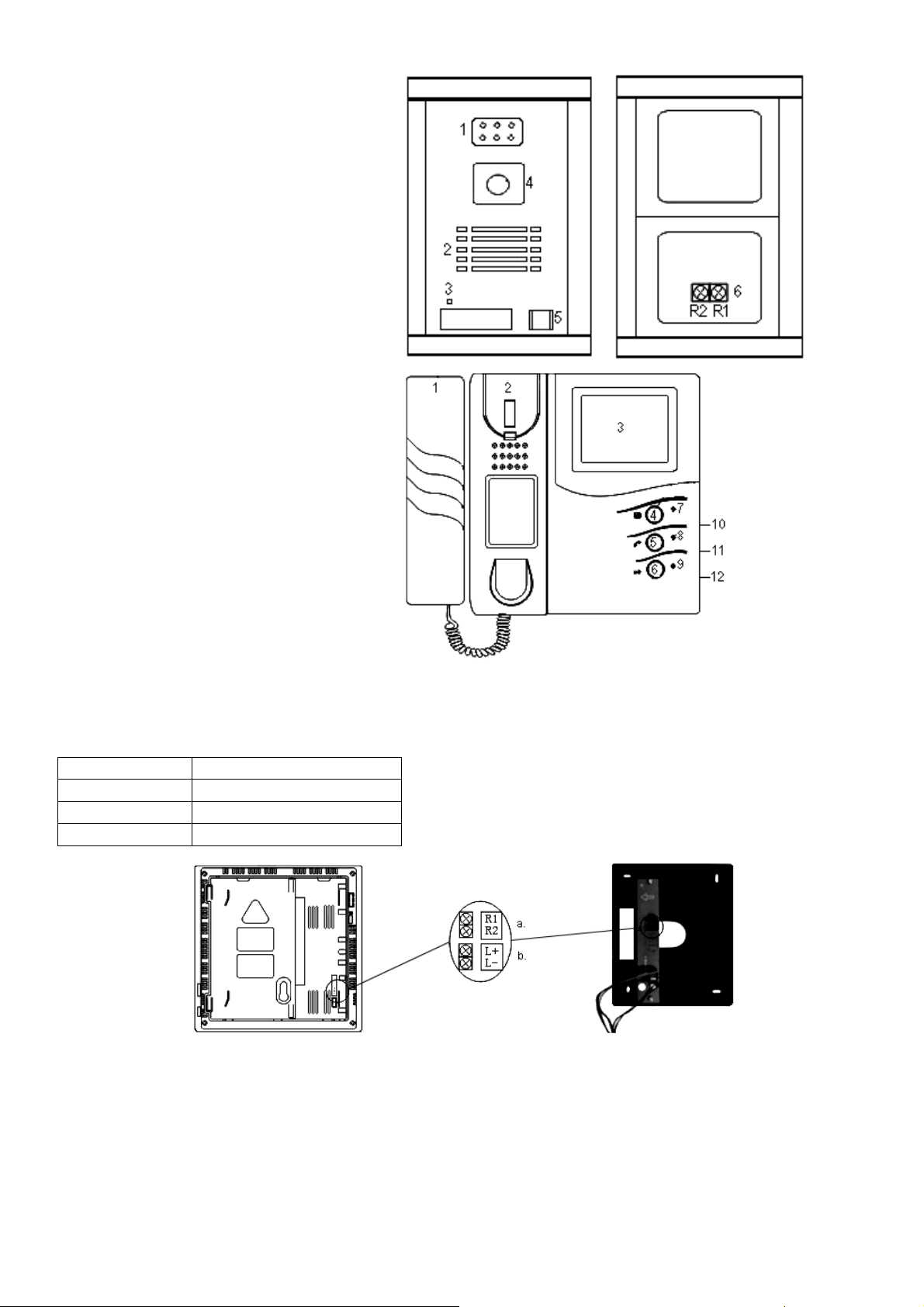
a. Camera Station
Fig. 1
1. IR LEDs
2. Speaker
3. Microphone
4. Camera
5. CALL button
6. Terminals (R1 and R2)
b. Monitor Station
1. Handset
Fig. 2
2. Standby switch
3. 4” screen
4. MONITOR button
5. Not used
6. UNLOCK button
7. Monitor power indicator
8. Power indicator
9. Unlock indicator
10. Volume
11. Brightness
12. Contrast
4. Wiring
Use 2-pole cables with following specifications:
Cable Length Wire Gauge
1 ~ 15m (incl.) 2 x 0.4mm² (2 x 26 AWG)
15 ~ 28m 2 x 0.5mm² (2 x 24 AWG)
28 ~ 50m 2 x 0.65mm² (2 x 22 AWG)
a) Connect the terminals from the monitor station to the terminals from the PCB (R1 → R1, R2 → R2).
b) Connect L+ and L- to the + and – of the electronic lock.
Fig. 3
CAMSET15 VELLEMAN
Page 5
5
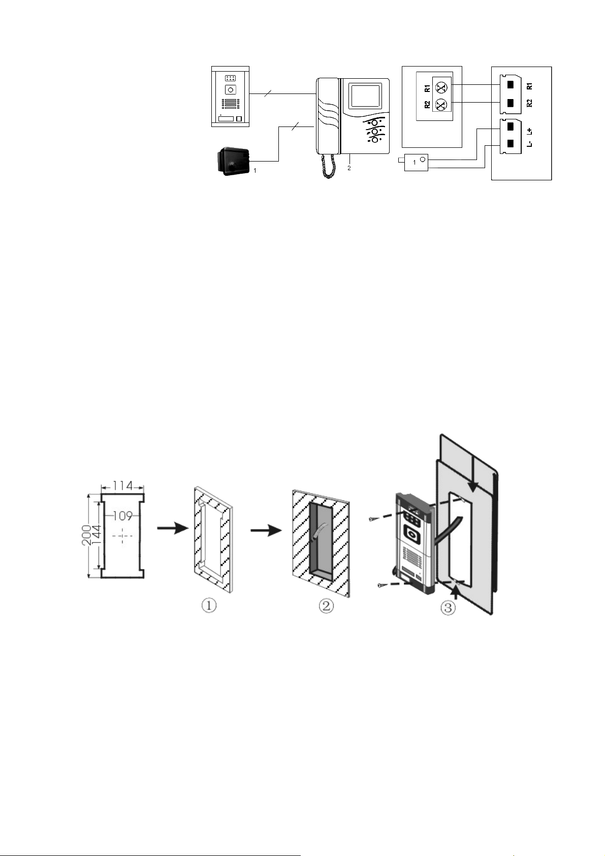
Powering through the Monitor
Fig. 4
1. Electronic lock (12V-1A) (not
incl.)
2. AC/DC power supply
5. Installation
• Keep the door phone system at least 1m away from a TV set or radio.
• Note that the system may be affected by radio frequency interference in areas near broadcasting station aerials.
• Keep all DC wiring at least 30cm away from 100 ~ 240VAC wiring, fluorescent lighting or dimmer switches.
Otherwise, cross the AC wiring in a 90° angle.
• The system may be affected by a strong electromagnetic interference present in the AC line.
• Install and fix the devices securely.
a. Installing the Camera Station in a Door
• Make a hole in the door referring to the measurements from figure 5. All measurements are in mm.
• Punch a hole in the bracket and fasten the bracket onto the backside of the door. Pass the wire through the
hole.
• Connect the wire to the camera station (see “Wiring”).
• Fasten the camera station to the bracket using the included cap head hex screws. Start by fastening the
bottom of the camera station. Slide the middle upper part up, fix the upper part and close the middle upper part.
Fig. 5
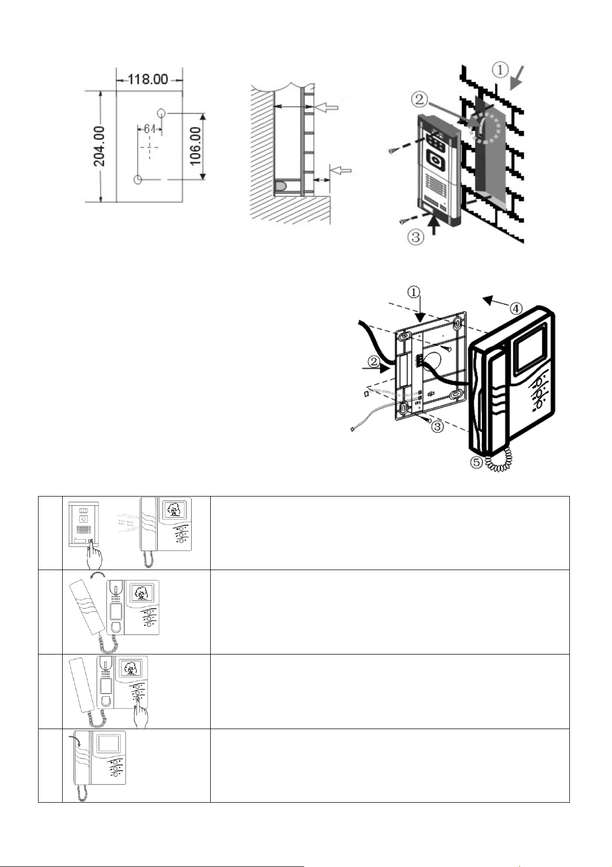
b. Installing the Camera Station into the Wall
• Make a hole in the wall referring to the measurements from figure 6. All measurements are in mm.
• Punch a hole in the bracket and fasten the bracket into the wall. Pass the wire through the hole.
• Connect the wire to the camera station (see “Wiring”).
• Fasten the camera station to the bracket using the included cap head hex screws. Start by fastening the
bottom of the camera station. Slide the middle upper part up, fix the upper part and close the middle upper part.
CAMSET15 VELLEMAN
Page 6
6
Fig. 6
c. Installing the Monitor Station
• Fasten the PCB onto the bracket.
• Connect the wire coming from the camera station to the
PCB (see “Wiring”).
• Fix the bracket onto the wall using the included screws.
• Connect the wire from the monitor station to the PCB (see
“Wiring”).
• Hang up the monitor station.
• Put the plug into the mains.
6. Operation
a. Communication with the Visitor
1.
Fig. 7
A chime will be heard when the CALL button on the camera station is
pressed. The monitor on the monitor station will display the image.
2.
Pick up the handset to communicate. If the handset is not picked up, the
indoor monitor will deactivate after 20 seconds.
3.
Press the UNLOCK button to unlock the door.
4.
Hang up the handset after communication.
CAMSET15 VELLEMAN
Page 7

7
b. Monitor Function
1.
Press the MONITOR button on the monitor station to display the outside
image.
7. Troubleshooting
Problem Solution
No image 1. Check the power plug.
2. Adjust the contrast.
3. Check the wiring of the terminals.
No sound 1. Check the handset.
2. Pull out the plug and insert again.
3. Check the wiring of the terminals.
Image does not disappear 1. Pull out the plug and insert again.
2. Put the handset down.
Blurry image 1. Check for interference signals from e.g. high-voltage wire, electric equipment, etc.
8. Technical Specifications
Monitor Station
Monitor 4” flat tube B/W CRT
Resolution 380 TV lines
Power Supply 240VAC / 50Hz
Power Consumption 10W
Operating Temperature -10°C ~ +50°C
Dimensions 215 x 205 x 55mm
Weight 1.5kg
Installation Mode wall-mount
Camera Station
Sensor ¼” B/W CMOS
Lens f=3.6mm
Illumination 0.1 lux
Light Source 6 IR LEDs
Power Supply 12VDC (powered through monitor)
Power Consumption 2.5W
Operating temperature -10°C ~ +50°C
Material aluminium
Dimensions 125 x 205 x 75mm
Weight 0.75kg
Accessories rain cover
The information in this manual is subject to change without prior notice.
CAMSET15 VELLEMAN
Page 8

8
CAMSET15 – Z/W VIDEO-INTERCOM
Wees voorzichtig bij de installatie: raak geen kabels aan die onder stroom staan om
dodelijke elektroshocks
1. Inleiding en kenmerken
Aan alle ingezetenen van de Europese Unie
Belangrijke milieu-informatie betreffende dit product
Dit symbool op het toestel of de verpakking geeft aan dat, als het na zijn levenscyclus wordt weggeworpen,
dit toestel schade kan toebrengen aan het milieu.
Gooi dit toestel (en eventuele batterijen) niet bij het gewone huishoudelijke afval; het moet bij een
gespecialiseerd bedrijf terechtkomen voor recyclage.
U moet dit toestel naar uw verdeler of naar een lokaal recyclagepunt brengen.
Respecteer de plaatselijke milieuwetgeving.
Hebt u vragen, contacteer dan de plaatselijke autoriteiten inzake verwijdering.
Dank u voor uw aankoop! Lees deze handleiding grondig voor u het toestel in gebruik neemt. Werd het toestel
beschadigd tijdens het transport, installeer het dan niet en raadpleeg uw dealer.
De CAMSET15 omvat:
• een camerapost
• een monitorpost met zwart-witmonitor
• een montagebeugel om de monitorpost tegen de muur te bevestigen
• een montagebeugel om de camerapost in de muur te bouwen
• schroeven & aansluitingskabel (15m)
• deze handleiding
2. Veiligheidsinstructies
te vermijden.
Bescherm dit toestel tegen regen en vochtigheid.
• De garantie geldt niet voor schade door het negeren van bepaalde richtlijnen in deze handleiding en uw dealer zal
de verantwoordelijkheid afwijzen voor defecten of problemen die hier rechtstreeks verband mee houden.
• Om veiligheidsredenen mag de gebruiker geen wijzigingen aanbrengen aan het toestel. Schade door wijzigingen
die de gebruiker heeft aangebracht aan het toestel vallen niet onder de garantie.
• De beschikbare netspanning mag niet hoger zijn dan de spanning in de specificaties achteraan de handleiding.
• De voedingskabel mag niet omgeplooid of beschadigd zijn. Laat uw dealer zo nodig een nieuwe kabel plaatsen.
• Houd tijdens de installatie uw handen droog om elektroshocks te vermijden.
• Monteer de monitorpost niet in een vochtige omgeving zoals bv. een badkamer.
• Demonteer de monitor- of de camerapost niet.
• Trek de stekker uit het stopcontact (trek nooit aan de kabel!) voordat u het toestel reinigt en als u het niet gebruikt.
• Ontkoppel de monitorpost van het lichtnet tijdens onweer om overbelasting te vermijden.
• Houd dit toestel uit de buurt van kinderen en onbevoegden.
• Schud het toestel niet dooreen. Vermijd brute kracht tijdens de installatie en de bediening van dit toestel.
• Gebruik het toestel enkel waarvoor het gemaakt is. Andere toepassingen kunnen leiden tot kortsluitingen,
brandwonden, elektrische schokken, enz. Bij onoordeelkundig gebruik vervalt de garantie.
• Maak het toestel geregeld schoon met een vochtige, niet-pluizend doek. Gebruik geen alcohol of solvent.
CAMSET15 VELLEMAN
Page 9

9
3. Omschrijving
a. Camerapost
Fig. 1
1. IR led’s
2. Luidspreker
3. Microfoon
4. Camera
5. CALL-knop
6. Terminals (R1 en R2)
b. Monitorpost
1. Hoorn
Fig. 2
2. Stand-by knop
3. 4” display
4. MONITOR-knop
5. Wordt niet gebruikt
6. UNLOCK-knop
7. Voedingsindicator monitor
8. Voedingsindicator
9. Indicator
10. Volume
11. Helderheid
12. Contrast
4. Bekabeling
Gebruik 2-aderige kabels met de volgende specificaties:
Kabellengte Draaddikte
1 ~ 15m (meegelev.) 2 x 0.4mm² (2 x 26 AWG)
15 ~ 28m 2 x 0.5mm² (2 x 24 AWG)
28 ~ 50m 2 x 0.65mm² (2 x 22 AWG)
a) Sluit de terminals van de monitorpost aan de terminals van de PCB (R1 → R1, R2 → R2).
b) Sluit L+ en L- aan de + respectievelijk de – van het elektronisch slot.
Fig. 3
CAMSET15 VELLEMAN
Page 10

10
Voeding via de monitor
Fig. 4
1. Elektronisch slot (12V-1A)
(niet meegelev.)
2. AC/DC voeding
5. Installatie
• Monteer het systeem op minstens 1m van een tv- of radiotoestel.
• Merk op dat, wanneer de CAMSET15 in een gebied met zendmasten wordt geïnstalleerd, dit storing kan
veroorzaken.
• Houd alle DC bekabeling op een afstand van minstens 30cm van 100 ~ 240VAC bekabeling, tl-buizen of
dimmertoestellen.
• De CAMSET15 kan sterke elektromagnetische storing uit de netspanning opvangen.
• Monteer en maak de toestellen stevig vast.
a. Montage van de camerapost in een deur
• Maak een opening in de deur volgens de afmetingen in figuur 5. Alle afmetingen uitgedrukt in mm.
• Maak een opening in de montagebeugel en maak deze vast achteraan de deur. Haal de kabel door de
opening in de montagebeugel.
• Sluit de kabel aan de camerapost (zie “Bekabeling”).
• Maak de camerapost vast aan de montagebeugel door middel van de meegeleverde inbusschroeven. Maak
eerst de onderkant van de camerapost vast. Open het lipje bovenaan in het midden, schroef vast en sluit het
lipje.
Fig. 5
b. Montage van de camerapost in een wand
• Maak een opening in de wand volgens de afmetingen in figuur 6. Alle afmetingen uitgedrukt in mm.
• Maak een opening in de montagebeugel en maak deze vast in de wand. Haal de kabel door de opening in de
montagebeugel.
• Sluit de kabel aan de camerapost (zie “Bekabeling”).
• Maak de camerapost vast aan de montagebeugel door middel van de meegeleverde inbusschroeven. Maak
eerst de onderkant van de camerapost vast. Open het lipje bovenaan in het midden, schroef vast en sluit het
lipje.
CAMSET15 VELLEMAN
Page 11

11
Fig. 6
c. Montage van de camerapost
• Maak de PCB vast aan de montagebeugel.
• Sluit de kabel van de camerapost aan de PCB (zie
“Bekabeling”).
• Maak de montagebeugel vast aan de wand door middel
van de meegeleverde schroeven.
• Sluit de kabel van de monitorpost aan de PCB (zie
“Bekabeling”).
• Hang de monitorpost aan de montagebeugel.
• Koppel de monitorpost aan het lichtnet.
6. Gebruik
a. Communicatie met de bezoeker
1.
Fig. 7
U hoort een bel van zodra iemand op de CALL-knop drukt. De monitor op de
monitorpost geeft het beeld weer.
2.
Neem de hoorn op om te communiceren. Neemt u de hoorn niet op, dan
schakelt de monitor na 20 seconden uit.
3.
Druk op de UNLOCK-knop om de deur te openen.
4.
Hang op na de communicatie.
CAMSET15 VELLEMAN
Page 12

12
b. Monitorfunctie
1.
Druk op de MONITOR-knop op de monitorpost om het beeld weer te geven.
7. Problemen en oplossingen
Probleem Oplossing
Geen beeld 1. Controleer de voedingsstekker.
2. Regel het contrast.
3. Controleer de bekabeling naar de terminals.
Geen geluid 1. Controleer de hoorn.
2. Trek de stekker uit het stopcontact en steek de stekker opnieuw in het stopcontact.
3. Controleer de bekabeling naar de terminals.
Beeld verdwijnt niet 1. Trek de stekker uit het stopcontact en steek de stekker opnieuw in het stopcontact.
2. Hang de hoorn op.
Onduidelijk beeld 1. Ga na of er geen interfererende signalen zijn van bv. hoogspanning, elektrische
toestellen, enz.
8. Technische specificaties
Monitorpost
Monitor 4” flat tube Z/W CRT
Resolutie 380 tv-lijnen
Voeding 240VAC / 50Hz
Verbruik 10W
Werktemperatuur -10°C ~ +50°C
Afmetingen 215 x 205 x 55mm
Gewicht 1.5kg
Installatie wandmontage
Camerapost
Sensor ¼” Z/W CMOS
Lens f=3.6mm
Verlichting 0.1 lux
Lichtbron 6 IR led’s
Voeding 12VDC (voeding via monitor)
Verbruik 2.5W
Werktemperatuur -10°C ~ +50°C
Materiaal aluminium
Afmetingen 125 x 205 x 75mm
Gewicht 0.75kg
Accessoires regenkap
De informatie in deze handleiding kan te allen tijde worden gewijzigd zonder voorafgaande kennisgeving.
CAMSET15 VELLEMAN
Page 13

13
CAMSET15 – INTERPHONE VIDÉO N/B
1. Introduction et caractéristiques
Aux résidents de l'Union européenne
Des informations environnementales importantes concernant ce produit
Ce symbole sur l'appareil ou l'emballage indique que l’élimination d’un appareil en fin de vie peut polluer
l'environnement.
Ne pas jeter un appareil électrique ou électronique (et des piles éventuelles) parmi les déchets municipaux
non sujets au tri sélectif ; une déchèterie traitera l’appareil en question.
Renvoyer les équipements usagés à votre fournisseur ou à un service de recyclage local.
Il convient de respecter la réglementation locale relative à la protection de l’environnement.
En cas de questions, contacter les autorités locales pour élimination.
Nous vous remercions de votre achat ! Lire la présente notice attentivement avant la mise en service de l’appareil. Si
l’appareil a été endommagé pendant le transport, ne pas l’installer et consulter votre revendeur.
Le CAMSET15 contient :
• un poste caméra extérieur
• un poste moniteur avec moniteur n/b
• un support de montage mural pour le poste moniteur
• une cassette d’encastrement pour le poste caméra
• vis & câble de connexion (15m)
• cette notice.
2. Prescriptions de sécurité
Être prudent lors de l’installation : toucher un câble sous tension peut causer des électrochocs mortels.
Protéger l’appareil contre la pluie et l’humidité.
• La garantie ne s’applique pas aux dommages survenus en négligeant certaines directives de cette notice et votre
revendeur déclinera toute responsabilité pour les problèmes et les défauts qui en résultent.
• Toute modification de l’appareil est interdite pour des raisons de sécurité. Les dommages occasionnés par des
modifications à l’appareil par le client, ne tombent pas sous la garantie.
• La tension réseau ne peut pas dépasser la tension mentionnée dans les spécifications à la fin de cette notice.
• Le câble d’alimentation ne peut pas être replissé ou endommagé. Demander à votre revendeur de renouveler le
câble d’alimentation si nécessaire.
• Veiller à avoir les mains sèches lors de l’installation du système pour éviter les électrochocs.
• Ne pas installer le poste moniteur dans un endroit humide comme p.ex. une salle de bains.
• Ne jamais démonter le poste caméra ni le poste moniteur.
• Débrancher l’appareil s’il n’est pas utilisé ou pour le nettoyer. Tirer la fiche pour débrancher l'appareil ; non pas le câble.
• Déconnecter l’appareil lors d’un orage pour éviter les surcharges.
• Garder votre CAMSET15 hors de la portée de personnes non qualifiées et de jeunes enfants.
• Éviter de secouer l’appareil et traiter l’appareil avec circonspection pendant l’installation et l’opération.
• N’utiliser votre CAMSET15 qu’à sa fonction prévue. Tout autre usage peut causer des courts-circuits, des
brûlures, des électrochocs etc. Un usage impropre annule d'office la garantie.
• Essuyer l’appareil régulièrement avec un chiffon humide non pelucheux. Éviter l’usage d’alcool et de solvants.
CAMSET15 VELLEMAN
Page 14

14
3. Description
a. Poste caméra
Fig. 1
1. LED’s IR
2. Haut-parleur
3. Microphone
4. Caméra
5. Touche CALL
6. Bornes (R1 et R2)
b. Poste moniteur
1. Combiné
Fig. 2
2. Mise en veille
3. Afficheur 4”
4. Touche MONITOR
5. Touche non utilisée
6. Touche UNLOCK
7. Indicateur de service de l’afficheur
8. Indicateur de puissance
9. Indicateur déverrouillage
10. Volume
11. Clarté
12. Contraste
4. Câblage
Utiliser des câbles à 2 brins avec les spécifications suivantes :
Longueur du câble Calibre
1 ~ 15m (incl.) 2 x 0.4mm² (2 x 26 AWG)
15 ~ 28m 2 x 0.5mm² (2 x 24 AWG)
28 ~ 50m 2 x 0.65mm² (2 x 22 AWG)
a) Connecter les bornes du poste moniteur aux bornes de la carte imprimée (R1 → R1, R2 → R2).
b) Connecter L+ et L- respectivement au + et au – du verrou électrique.
Fig. 3
CAMSET15 VELLEMAN
Page 15

15
Alimentation par le poste moniteur
Fig. 4
1. Verrou électrique (12V-1A)
(non incl.)
2. alimentation CA/CC
5. Installation
• Installer le système à une distance minimale de 1m d’un téléviseur un d’un poste de radio.
• Le système peut être sujet à des interférences radio dans un endroit à proximité d’antennes d’émission.
• Tenir tout câblage CC à une distance minimale de 30cm de câblage 100 ~ 240VCA, d’éclairage luminescent et
d’interrupteur de variateur.
• Le système peut être sujet à une forte interférence électromagnétique présente dans le réseau électrique.
• Fixer les appareils solidement.
a. Installation du poste caméra dans une porte
• Percer un trou dans la porte en vous référant aux dimensions mentionnées dans l’illustration n°5. Toutes les
dimensions sont mentionnées en mm.
• Percer un trou dans le support de montage et fixer le support sur la face arrière de la porte. Passer le câble
par le trou dans le support.
• Connecter le câble au poste caméra (voir « Câblage »).
• Fixer le poste caméra au support à l’aide des vis à empreinte hexagonale fournies. Commencer par fixer la
partie inférieure du poste caméra. À présent, glisser la languette au milieu de la partie supérieure vers le haut,
fixer la partie supérieure et refermer la languette.
Fig. 5
b. Installation du poste caméra dans une paroi
• Percer un trou dans la paroi en vous référant aux dimensions mentionnées dans l’illustration n°6. Toutes les
dimensions sont mentionnées en mm.
• Percer un trou dans le support de montage et fixer le support dans la paroi. Passer le câble par le trou dans le
support.
• Connecter le câble au poste caméra (voir « Câblage »).
• Fixer le poste caméra au support à l’aide des vis à empreinte hexagonale fournies. Commencer par fixer la
partie inférieure du poste caméra. À présent, glisser la languette au milieu de la partie supérieure vers le haut,
fixer la partie supérieure et refermer la languette.
CAMSET15 VELLEMAN
Page 16

16
Fig. 6
c. Installation du poste moniteur
• Fixer la carte imprimée au support de montage.
• Connecter le câble du poste caméra à la carte imprimée
(voir « Câblage »).
• Fixer le support à la paroi à l’aide des vis fournies.
• Connecter le câble du poste moniteur à la carte imprimée
(voir « Câblage »).
• Fixer le poste moniteur au support.
• Raccorder le poste moniteur au réseau électrique.
6. Emploi
a. Communication avec un visiteur
1.
Fig. 7
Vous entendrez une sonnerie des qu’une personne enfonce la touche CALL
su le poste caméra. L’image sera affichée sur le poste moniteur.
2.
Décrocher pour communiquer. Si vous ne décrochez pas, l’afficheur sera
automatiquement désactivé près un délai de 20 secondes.
3.
Enfoncer la touche UNLOCK pour ouvrir la porte.
4.
Raccrocher après la communication.
CAMSET15 VELLEMAN
Page 17

17
b. Utilisation de l’afficheur
1.
Enfoncer la touche MONITOR sur le poste moniteur pour afficher l’image.
7. Problèmes et solutions
Problème Solutions
Pas d’image 1. Vérifier la fiche d’alimentation.
2. Régler le contraste.
3. Vérifier le câblage des bornes.
Pas de son 1. Vérifier le cornet.
2. Déconnecter le poste moniteur du réseau électrique et reconnecter.
3. Vérifier le câblage des bornes.
L’image ne disparaît pas 1. Déconnecter le poste moniteur du réseau électrique et reconnecter.
2. Raccrocher.
Image saturée 1. Vérifier la présence de signaux d’interférence provenant de p.ex. une ligne haute
tension, appareils électriques, etc.
8. Spécifications techniques
Poste moniteur
Afficheur CRT N/B 4” plat
Résolution 380 lignes TV
Alimentation 240VCA / 50Hz
Consommation 10W
Température de service -10°C ~ +50°C
Dimensions 215 x 205 x 55mm
Poids 1.5kg
Installation installation murale
Poste caméra
Capteur CMOS N/B ¼”
Objectif f=3.6mm
Illumination 0.1 lux
Source lumineuse 6 LEDs IR
Alimentation 12VCC (alimentation via moniteur)
Consommation 2.5W
Température de service -10°C ~ +50°C
Matériau aluminium
Dimensions 125 x 205 x 75mm
Poids 0.75kg
Accessoires protection anti-pluie
Toutes les informations présentées dans cette notice peuvent être modifiées sans notification préalable.
CAMSET15 VELLEMAN
Page 18

18
CAMSET15 – VIDEOPORTERO B/N
Cuidado durante la instalación: puede sufrir una peligrosa descarga eléctrica al tocar los cables con un
1. Introducción & Características
A los ciudadanos de la Unión Europea
Importantes informaciones sobre el medio ambiente concerniente a este producto
Este símbolo en este aparato o el embalaje indica que, si tira las muestras inservibles, podrían dañar el
medio ambiente.
No tire este aparato (ni las pilas, si las hubiera) en la basura doméstica; debe ir a una empresa
especializada en reciclaje. Devuelva este aparato a su distribuidor o a la unidad de reciclaje local.
Respete las leyes locales en relación con el medio ambiente.
Si tiene dudas, contacte con las autoridades locales para residuos.
¡Gracias por haber comprado el CAMSET15! Lea atentamente las instrucciones del manual antes de utilizarlo.
Si el aparato ha sufrido algún daño en el transporte no lo instale y póngase en contacto con su distribuidor.
El CAMSET15 contiene:
• una cámara
• un monitor con pantalla B/N
• un soporte de montaje mural para el monitor
• un soporte de montaje para empotrar la cámara
• tornillos & cable de conexión (15m)
• este manual del usuario.
2. Instrucciones de seguridad
voltaje peligroso.
No exponga este equipo a lluvia o humedad.
• Daños causados por descuido de las instrucciones de seguridad de este manual invalidarán su garantía y su
distribuidor no será responsable de ningún daño u otros problemas resultantes.
• Por razones de seguridad, las modificaciones no autorizadas del aparato están prohibidas. Los daños causados
por modificaciones no autorizadas, no están cubiertos por la garantía.
• Asegúrese de que la tensión de red no sea mayor que la tensión indicada en las especificaciones.
• No aplaste el cable de alimentación y protéjalo contra posibles daños causados por algún tipo de superficie
afilada. Si es necesario, pida a su distribuidor reemplazar el cable de alimentación.
• Asegúrese de que tenga las manos secas durante la instalación del sistema para evitar descargas eléctricas.
• No instale el monitor en un lugar húmedo como p.ej. un cuarto de baño.
• Nunca desmonte la cámara ni el monitor.
• Desconecte siempre el aparato si no va a usarlo durante un largo período de tiempo o antes de limpiarlo. Tire
siempre del enchufe para desconectar el cable de red, nunca del propio cable.
• Desconecte el aparato durante una tormenta para evitar las sobrecargas.
• Mantenga el CAMSET15 lejos del alcance de personas no capacitadas y niños.
• No agite el aparato. Evite usar excesiva fuerza durante la instalación y la reparación.
• Utilice sólo el CAMSET15 para aplicaciones descritas en este manual a fin de evitar p.ej. cortocircuitos,
quemaduras, descargas eléctricas, etc. Un uso desautorizado puede causar daños y anula la garantía
completamente.
• Limpie el aparato regularmente con un paño húmedo y sin pelusas. Evite el uso de alcohol y de disolventes.
CAMSET15 VELLEMAN
Page 19

19
3. Descripción
a. Cámara
Fig. 1
1. LEDs IR
2. Altavoz
3. Micrófono
4. Cámara
5. Tecla CALL
6. Bornes (R1 y R2)
b. Monitor
1. Auricular
Fig. 2
2. tecla ‘stand-by’
3. Pantalla de 4”
4. Tecla MONITOR
5. Tecla sin uso
6. Tecla UNLOCK
7. Indicador de alimentación de la pantalla
8. Indicador de alimentación
9. Indicador de desbloqueo
10. Volumen
11. Luminosidad
12. Contraste
4. Cableado
Utilice cables de 2 hilos con las especificaciones siguientes:
Longitud del cable Espesor del cable
1 ~ 15m (incl.) 2 x 0.4mm² (2 x 26 AWG)
15 ~ 28m 2 x 0.5mm² (2 x 24 AWG)
28 ~ 50m 2 x 0.65mm² (2 x 22 AWG)
a) Conecte los bornes del puesto de monitor a los bornes de la placa de circuitos (R1 → R1, R2 → R2).
b) Conecte L+ y L- respectivamente al + y al – de la cerradura eléctrica.
Fig. 3
CAMSET15 VELLEMAN
Page 20

20
Alimentación por el monitor
Fig. 4
1. cerradura eléctrica (12V-1A)
(no incl.)
2. alimentación CA/CC
5. Instalación
• Instale el sistema a una distancia mín. de 1m de un televisor o una radio.
• Instalar el sistema en un lugar con postes para antenas puede causar interferencias.
• Mantenga el cableado CC a una distancia mín. de 30cm del cableado 100 ~ 240VCA, iluminación fluorescente y
sistemas con dimmer.
• El aparato puede captar fuertes interferencias electromagnéticas presentes en la red eléctrica.
• Fije los aparatos fuertemente.
a. Instalar la cámara en una puerta
• Taladre un agujero en la puerta (véase las dimensiones mencionadas en la fig. n° 5). Todas las dimensiones
están indicadas en mm.
• Taladre un agujero en el soporte de montaje y fije el soporte en la parte trasera de la puerta. Pase el cable por
el agujero del soporte.
• Conecte el cable a la cámara (véase « Cableado »).
• Fije la cámara con los tornillos de hexágono interior (incl.) al soporte. Primero, fije la parte inferior de la
cámara. Ahora, deslice la lengüeta de la parte superior en el centro hacia arriba, fije la parte superior y vuelva
a cerrar la lengüeta.
Fig. 5
b. Instalar la cámara en una pared
• Taladre un agujero en la pared (véase las dimensiones mencionadas en la fig. n° 6). Todas las dimensiones
están indicadas en mm.
• Taladre un agujero en el soporte de montaje y fije el soporte en la pared. Pase el cable por el agujero del
soporte.
• Conecte el cable a la cámara (véase « Cableado »).
• Fije la cámara con los tornillos hexagonales (incl.) al soporte. Primero, fije la parte inferior de la cámara. Ahora,
deslice la lengüeta de la parte superior en el centro hacia arriba, fije la parte superior y vuelva a cerrar la
lengüeta.
CAMSET15 VELLEMAN
Page 21

21
Fig. 6
c. Instalar el monitor
• Fije la placa de circuitos al soporte de montaje.
• Conecte el cable de la cámara a la placa de circuitos
(véase « Cableado »).
• Fije el soporte con los tornillos incluidos a la pared.
• Conecte el cable del monitor a la placa de circuitos (véase
« Cableado »).
• Fije el monitor al soporte.
• Conecte el monitor a la red eléctrica.
6. Uso
a. Comunicar con un visitante
1.
Fig. 7
Oirá un timbre en cuanto una persona pulse la tecla CALL de la cámara. La
imagen se visualizará en el monitor.
2.
Descuelgue para comunicar. Si no descuelga, la pantalla se desactivará
automáticamente después de 20 segundos.
3.
Pulse la tecla UNLOCK para abrir la puerta.
4.
Cuelgue después de la comunicación.
CAMSET15 VELLEMAN
Page 22

22
b. Utilizar la pantalla
1.
Pulse la tecla MONITOR del monitor para visualizar la imagen.
7. Solución de problemas
Problema Soluciones
No hay imagen 1. Controle el conector de alimentación.
2. Ajuste el contraste.
3. Controle el cableado de los bornes.
No hay sonido 1. Controle el auricular.
2. Desconecte el monitor de la red eléctrica y vuelva a conectarlo.
3. Controle el cableado de los bornes.
La imagen no desaparece 1. Desconecte el monitor de la red eléctrica y vuelva a conectarlo.
2. Cuelge.
Imagen saturada 1. Controle la presencia de señales de interferencia provenientes de p.ej. una línea
de alta tensión, aparatos eléctricos, etc.
8. Especificaciones
Monitor
Pantalla tubo plano B/N CRT de 4"
Resolución 380 líneas TV
Alimentación 240VCA / 50Hz
Consumo 10W
Temperatura de funcionamiento -10°C ~ +50°C
Dimensiones 215 x 205 x 55mm
Peso 1.5kg
Instalación montaje mural
Cámara
Sensor CMOS B/N de ¼”
Óptica f=3.6mm
Iluminación 0.1 lux
Fuente luminosa 6 LEDs IR
Alimentación 12VCC (por el monitor)
Consumo 2.5W
Temperatura de funcionamiento -10°C ~ +50°C
Material aluminio
Dimensiones 125 x 205 x 75mm
Peso 0.75kg
Accesorios protección contra la lluvia
Se pueden modificar las especificaciones y el contenido de este manual sin previo aviso.
CAMSET15 VELLEMAN
Page 23

23
CAMSET15 – VIDEO-TÜRSPRECHANLAGE - S/W
Seien Sie während der Installation des Gerätes sehr vorsichtig: das Be
rühren von unter Spannung stehenden
1. Einführung & Eigenschaften
An alle Einwohner der Europäischen Union
Wichtige Umweltinformationen über dieses Produkt
Dieses Symbol auf dem Produkt oder der Verpackung zeigt an, dass die Entsorgung dieses Produktes nach
seinem Lebenszyklus der Umwelt Schaden zufügen kann.
Entsorgen Sie die Einheit (oder verwendeten Batterien) nicht als unsortiertes Hausmüll; die Einheit oder
verwendeten Batterien müssen von einer spezialisierten Firma zwecks Recycling entsorgt werden.
Diese Einheit muss an den Händler oder ein örtliches Recycling-Unternehmen retourniert werden.
Respektieren Sie die örtlichen Umweltvorschriften.
Wir bedanken uns für den Kauf der CAMSET15! Lesen Sie vor Inbetriebnahme diese Bedienungsanleitung sorgfältig
durch. Überprüfen Sie, ob Transportschäden vorliegen. Sollte dies der Fall sein, verwenden Sie das Gerät nicht und
wenden Sie sich an Ihren Händler.
Die CAMSET15 umfasst:
• eine Kamera-Einheit
• eine Monitor-Einheit mit S/W-Monitor
• Montagebügel zum Montage der Monitor-Einheit an der Wand
• Montagebügel zum Einbauen der Kamera-Einheit an der Wand
• Schrauben & Anschlusskabel (15m)
• diese Bedienungsanleitung
2. Sicherheitshinweise
Leitungen könnte zu lebensgefährlichen elektrischen Schlägen führen.
Schützen Sie das Gerät vor Feuchtigkeit und Feuchte.
• Bei Schäden, die durch Nichtbeachtung der Bedienungsanleitung verursacht werden, erlischt der
Garantieanspruch. Für daraus resultierende Folgeschäden übernimmt der Hersteller keine Haftung.
• Eigenmächtige Veränderungen sind aus Sicherheitsgründen verboten. Bei Schäden verursacht durch
eigenmächtige Änderungen erlischt der Garantieanspruch.
• Vergewissern Sie sich, dass die anzuschließende Netzspannung nicht höher ist als die Netzspannung
beschrieben im Punkt 8. "Technische Daten".
• Achten Sie darauf, dass die Netzleitung nicht gequetscht oder durch scharfe Kanten beschädigt werden kann. Bei
Beschädigungen soll eine Fachkraft das Kabel ersetzen.
• Halten Sie die Hände während der Installation trocken um elektrische Schläge zu vermeiden.
• Installieren Sie die Monitor-Einheit nicht in einer feuchten Umgebung wie z.B. Badezimmer.
• Demontieren Sie die Monitor- oder Kamera-Einheit nicht.
• Trennen Sie das Gerät bei Nichtbenutzung und vor jeder Reinigung vom Netz. Fassen Sie dazu den Netzstecker
an der Grifffläche an und ziehen Sie nie an der Netzleitung.
• Trennen Sie die Monitor-Einheit vom Netz während eines Gewitters um Überbelastung zu vermeiden.
• Halten Sie Kinder und Unbefugte vom Gerät fern.
• Vermeiden Sie Erschütterungen. Vermeiden Sie rohe Gewalt während der Installation und Bedienung des Gerätes.
• Verwenden Sie das Gerät nur für Anwendungen in dieser Bedienungsanleitung beschrieben, sonst kann dies zu
Schäden am Produkt führen und erlischt der Garantieanspruch. Jede andere Verwendung ist mit Gefahren wie
Kurzschluss, Brandwunden, elektrischem Schlag, usw. verbunden.
• Verwenden Sie zur Reinigung ein feuchtes, fusselfreies Tuch. Verwenden Sie auf keinen Fall Alkohol oder
irgendwelche Lösungsmittel.
CAMSET15 VELLEMAN
Page 24

24
3. Umschreibung
a. Kamera-Einheit
Fig. 1
1. Infrarot-LEDs
2. Lautsprecher
3. Mikrofon
4. Kamera
5. CALL-Taste
6. Anschlüsse (R1 und R2)
b. Monitor-Einheit
1. Hörer
Fig. 2
2. ‘Stand-by’-Taste
3. 4” Display
4. MONITOR-Taste
5. wird nicht verwendet
6. UNLOCK-Taste
7. Versorgungsanzeige Monitor
8. Versorgungsanzeige
9. Anzeige
10. Lautstärke
11. Helligkeit
12. Kontrast
4. Verkabelung
Verwenden Sie 2-polige Kabel mit folgenden technischen Daten:
Kabellänge Drahtdurchmesser
1 ~ 15m (mitgeliefert) 2 x 0.4mm² (2 x 26 AWG)
15 ~ 28m 2 x 0.5mm² (2 x 24 AWG)
28 ~ 50m 2 x 0.65mm² (2 x 22 AWG)
a) Verbinden Sie die Anschlüsse der Monitor-Einheit mit den Anschlüssen der Leiterplatte (R1 → R1, R2 → R2) an.
b) Verbinden Sie L+ und L- mit + und – vom elektronischen Türschloss.
Fig. 3
CAMSET15 VELLEMAN
Page 25

25
Stromversorgung über den Monitor
Fig. 4
1. elektronisches Türschloss
(12V-1A) (nicht mitgeliefert)
2. AC/DC Stromversorgung
5. Installation
• Montieren Sie das System in einer Entfernung von mindestens 1m des Fernseh- oder Rundfunkgerätes.
• Beobachten Sie dass, wenn die CAMSET15 in einem Gebiet mit Sendemasten installiert wird, dies Störungen
verursachen kann.
• Halten Sie alle DC-Verkabelung in einer Entfernung von mindestens 30cm vom 100 ~ 240VAC Verkabelung,
Leuchtstoffröhre oder Dimmergeräte.
• Die CAMSET15 kann starke elektromagnetische Störungen aus der Netzspannung auffangen.
• Montieren Sie die Geräte und machen Sie diese sehr gut fest.
a. Die Kamera-Einheit in einer Tür montieren
• Machen Sie eine Öffnung in der Tür (siehe Abmessungen in Abb. 5). Alle Abmessungen stehen in mm.
• Machen Sie eine Öffnung im Montagebügel und befestigen Sie diese auf der Rückseite der Tür. Stecken Sie
das Kabel durch die Öffnung im Montagebügel.
• Verbinden Sie das Kabel mit der Kamera-Einheit (siehe “Verkabelung”).
• Befestigen Sie die Kamera-Einheit mit den mitgelieferten Innensechskantschrauben an dem Montagebügel.
Befestigen Sie zuerst die Unterseite der Kamera-Einheit. Öffnen Sie die Lasche obenan in der Mitte,
schrauben Sie fest und schließen Sie die Lasche wieder.
Fig. 5
b. Die Kamera-Einheit an einer Wand montieren
• Machen Sie eine Öffnung in der Wand (siehe Abmessungen in Abb. 6). Alle Abmessungen stehen in mm.
• Machen Sie eine Öffnung im Montagebügel und befestigen Sie diese auf der Rückseite der Tür. Stecken Sie
das Kabel durch die Öffnung im Montagebügel.
• Verbinden Sie das Kabel mit der Kamera-Einheit (siehe “Verkabelung”).
• Befestigen Sie die Kamera-Einheit mit den mitgelieferten Innensechskantschrauben an dem Montagebügel.
Befestigen Sie zuerst die Unterseite der Kamera-Einheit. Öffnen Sie die Lasche obenan in der Mitte,
schrauben Sie fest und schließen Sie die Lasche wieder.
CAMSET15 VELLEMAN
Page 26

26
Fig. 6
c. Die Monitor-Einheit montieren
• Befestigen Sie die Leiterplatte an dem Montagebügel.
• Verbinden Sie das Kabel der Kamera-Einheit mit der
Leiterplatte (siehe “Verkabelung”).
• Befestigen Sie den Montagebügel mit den mitgelieferten
Schrauben an der Wand.
• Verbinden Sie das Kabel der Monitor-Einheit mit der
Leiterplatte (siehe “Verkabelung”).
• Befestigen Sie die Monitor-Einheit am Montagebügel.
• Verbinden Sie die Monitor-Einheit mit dem Stromnetz.
6. Gebrauch
a. Kommunikation mit einem Besucher
1.
Fig. 7
Der Klingelton ertönt sobald jemand die CALL-Taste drückt. Der Monitor zeigt
kein Bild.
2.
Heben Sie den Hörer ab, damit Sie kommunizieren können. Wenn Sie den
Hörer nicht abheben, schaltet der Monitor sich nach 20 Sekunden
automatisch ab.
3.
Drücken Sie die UNLOCK-Taste um die Tür zu öffnen.
4.
Legen Sie den Hörer nach der Kommunikation wieder auf.
CAMSET15 VELLEMAN
Page 27

27
b. Monitor-Funktion
1.
Drücken Sie die MONITOR-Taste der Monitor-Einheit um das Bild zu zeigen.
7. Problemlösung
Problem Lösung
Kein Bild 1. Kontrollieren Sie den Stecker.
2. Regeln Sie den Kontrast.
3. Kontrollieren Sie Verkabelung zu den Klemmen.
Bild ohne Ton 1. Kontrollieren Sie den Hörer.
2. Ziehen Sie den Stecker aus der Steckdose und dann wieder ein.
3. Kontrollieren Sie Verkabelung zu den Klemmen.
Monitor schaltet nicht aus 1. Ziehen Sie den Stecker aus der Steckdose und dann wieder ein.
2. Nehmen Sie den Hörer ab und legen Sie ihn erneut auf.
Verformtes Bild 1. Kontrollieren Sie ob es keine Störungen von z.B. Hochspannung, elektrischen
Geräten, usw. gibt.
8. Technische Daten
Monitor-Einheit
Monitor CRT 4" Flat Tube S/W
Auflösung 380TV-Zeilen
Stromversorgung 240VAC / 50Hz
Stromverbrauch 10W
Betriebstemperatur -10°C ~ +50°C
Abmessungen 215 x 205 x 55mm
Gewicht 1.5kg
Installation Wandmontage
Kamera-Einheit
Sensor ¼” Z/W CMOS
Objektiv f=3.6mm
Beleuchtung 0.1 lux
Lichtquelle 6 IR LEDs
Stromversorgung 12VDC (Stromversorgung über Monitor)
Stromverbrauch 2.5W
Betriebstemperatur -10°C ~ +50°C
Material Aluminium
Abmessungen 125 x 205 x 75mm
Gewicht 0.75kg
Zubehör Regenschutz
Alle Änderungen ohne vorherige Ankündigung vorbehalten.
CAMSET15 VELLEMAN
 Loading...