

Page 1
CAMSET14 1 VELLEMAN
CAMSET14 – B/W VIDEO DOOR PHONE
1. Introduction & Features
To all residents of the European Union
Important environmental information about this product
This symbol on the device or the package indicates that disposal of the device after its lifecycle could harm the environment.
Do not dispose of the unit (or batteries) as unsorted municipal waste; it should be taken to a specialised company for recycling.
This device should be returned to your distributor or to a local recycling service.
Respect the local environmental rules.
If in doubt, contact your local waste disposal authorities
.
Thank you for buying the CAMSET14! Please read the manual thoroughly before bringing this device into service.
If the device was damaged in transit, don't install or use it and contact your dealer.
The CAMSET14 includes:
• a camera unit with rain cover
• an monitor unit + connection cable of 15m
• a bracket to mount the interphone to the wall
• screws & screwdriver
• this manual
2. Safety Instructions
• Damage caused by disregard of certain guidelines in this manual is not covered by the warranty and the dealer will
not accept responsibility for any ensuing defects or problems.
• All modifications of the device are forbidden for safety reasons. Damage caused by user modifications to the
device is not covered by the warranty.
• Make sure that the available voltage does not exceed the voltage stated in the specifications of this manual.
• Do not crimp the power cord and protect it against damage. Have an authorised dealer replace it if necessary.
• Keep the device away from children and unauthorised users.
• Do not shake the device. Avoid brute force when installing or operating the device.
• Only use the device for its intended purpose. Using the device in an unauthorised way will void the warranty.
• Wipe the device regularly with a moist, lint-free cloth. Do not use alcohol or solvents.
3. Installation
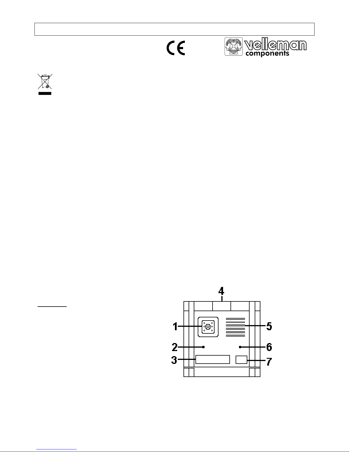
Camera unit
1. camera + infrared LEDs for illumination
2. microphone
3. name tag
4. screw cover (move upwards to reveal screw)
5. speaker
6. light intensity sensor
7. call button
Fig.1
Page 2

CAMSET14 2 VELLEMAN
Monitor unit
1. image impedance switch
2. handset
3. 4" b/w monitor
4. volume control
5. brightness control
6. contrast control
7. "unlock" LED
8. monitor button
9. intercom button
10. unlock button
11. power LED
1. First install the cable. To connect the camera and monitor units, a 75ohm 5C2V coax cable is recommended.
2. Push the camera unit's screw cover (fig.1 #4) upwards and
remove the (hex) screw under it. Flip the camera unit away
from the rain cover. Now you can also remove the bottom
screw if you want to separate them completely. Pull the wire
through the hole in the rain cover and mount the rain cover
to the wall (see fig. 3). Connect the wire to the camera unit,
flip the camera unit up (or fasten the bottom screw and flip it
up) and fasten it with the top screw. Pull the screw cover down (fig.1 #4).
3. For the monitor unit: pull the wire through the hole in the mounting
bracket and mount the bracket to the wall. Connect the wire to the
monitor unit. Put the monitor unit on the 4 pins on the bracket (fig.4 #1)
and fasten it by means of a screw on either side of the unit (fig.4 #2). Set
the impedance switch of the monitor unit (fig.2 #1) to "75Ω".
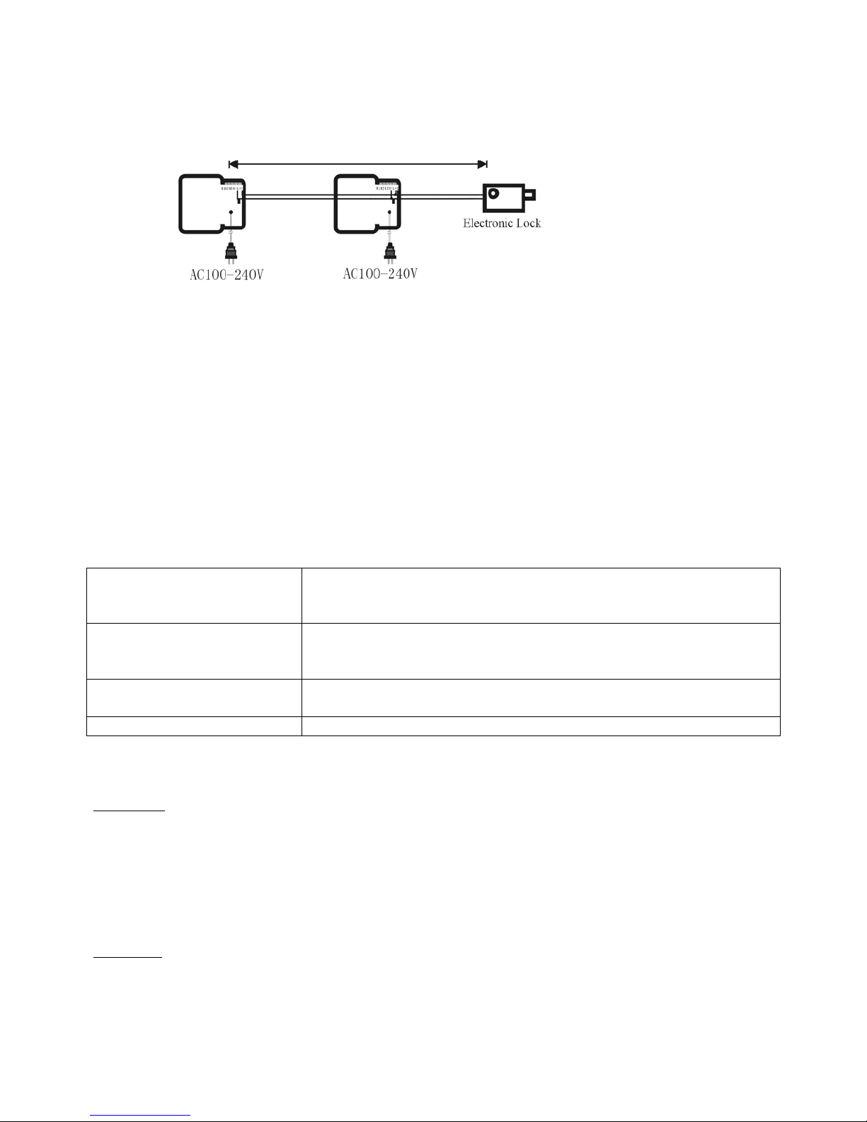
4. It is possible to connect up to three monitor units to one camera unit,
providing that the total cable length does not exceed 100m. Additional
monitor units are available separately (order code CAMSET14/MON).
Connect the monitor units as in the figure below. The image impedance
switch (fig.2 #1) of the last unit must be set to "75Ω", the others to "OFF".
5. Wiring (see fig.5)
You can attach 1,2 or 3 monitor units. If you connect only one monitor
unit, you should switch the impedance matching switch (see fig. 2 #1) of
that unit to "75Ω". If you connect two or three monitor units, you should
always switch the impedance matching switch of the last unit in the
series to "75Ω" (2 monitor units = impedance switch of the second unit, 3
monitor units = impedance switch of the third unit).
6. It is also possible to connect an electronic door lock (not included) to the monitor unit. This can be done by means
of the 2-pin connector (L+ and L-) at the back of the monitor unit. We recommend that no more than 2 monitor
units be connected to an electronic lock (max. cable length 25m).
Fig.
3
Fig.
4
Fig.
5
Fig. 2
Page 3
CAMSET14 3 VELLEMAN
RVV 2 x 32/0.2 W/1.0mm² cut area wire for electronic lock connection (reference distance < 25m)
4. Operation
• When the call button (fig.1 #7) is pressed, the monitor unit emits a chime sound and the visitor's image appears.
• Pick up the handset to communicate with the visitor. Put it down to end the communication - the monitor will be
switched off simultaneously.
• If there is no communication (handset is not picked up), the monitor will automatically switch off after 30 seconds.
• If you want to let the visitor in and an electronic door lock is installed, press the unlock button (fig.2 #10).
• Communication can also be established from inside: pick up the handset and press the 'monitor' button (fig.2 #8).
• Verify if anyone is at the door by pressing the monitor button without picking up the handset. To switch the monitor
off again, pick up the handset and put it back, or let the monitor auto switch off after 30 seconds.
• If more than 1 monitor unit is installed, the intercom button (fig.2 #9) can be used to call another monitor unit.
5. Troubleshooting
No image on the monitor 1. Check the power plug.
2. Check the contrast & brightness setting.
3. Check the wiring.
Image but no sound 1. Check the handset spring wire.
2. Check the power plug (unplug and replug it).
3. Check the wiring.
Monitor remains on 1. Pick up the handset and put it back.
2. Unplug and replug the power plug.
Distorted image Check for interfering cables (e.g. high voltage wire) or magnetic fields.
6. Technical Specifications
Camera unit (order code spare camera unit: CAMSET14/CAM)
Camera 1/4" CCD/CMOS
Resolution 352x288
Lens / angle F4.9mm / H = 40°; V = 31°; D = 50°
Min. illumination 0.1Lux
Light source 6 infrared LEDs
Dimensions 170x158x55mm
Monitor unit (order code additional monitor units: CAMSET14/MON)
Power Supply 100-240Vac
CRT 4" flat b/w
Resolution
≥380 TV lines
Call sound "ding dong" chime
Page 4

CAMSET14 4 VELLEMAN
Power Consumption 4-7W standby / 13-25W operating
Dimensions 222x215x56mm
Cable length 15m
The information in this manual is subject to change without prior notice.
CAMSET14 – Z/W VIDEO INTERCOMSYSTEEM
1. Inleiding en kenmerken
Aan alle ingezetenen van de Europese Unie
Belangrijke milieu-informatie betreffende dit product
Dit symbool op het toestel of de verpakking geeft aan dat, als het na zijn levenscyclus wordt weggeworpen, dit toestel schade kan
toebrengen aan het milieu.
Gooi dit toestel (en eventuele batterijen) niet bij het gewone huishoudelijke afval; het moet bij een gespecialiseerd bedrijf
terechtkomen voor recyclage.
U moet dit toestel naar uw verdeler of naar een lokaal recyclagepunt brengen.
Respecteer de plaatselijke milieuwetgeving.
Heeft u vragen, contacteer dan de plaatselijke autoriteiten inzake verwijdering
.
Dank u voor uw aankoop! Lees deze handleiding grondig voor u het toestel in gebruik neemt. Als het toestel werd
beschadigd tijdens het transport, installeer het dan niet en raadpleeg uw dealer.
De CAMSET14 omvat:
• een camerapost met regenkap
• een monitorpost + verbindingskabel van 15m
• een montagebeugel om de monitorpost tegen de muur te bevestigen
• schroeven & schroevendraaier
• deze handleiding
2. Veiligheidsinstructies
• De garantie geldt niet voor schade door het negeren van bepaalde richtlijnen in deze handleiding en uw dealer zal
de verantwoordelijkheid afwijzen voor defecten of problemen die hier rechtstreeks verband mee houden.
• Om veiligheidsredenen mag de gebruiker geen wijzigingen aanbrengen aan het toestel. Schade door wijzigingen
die de gebruiker heeft aangebracht aan het toestel vallen niet onder de garantie.
• De beschikbare netspanning mag niet hoger zijn dan de spanning in de specificaties achteraan de handleiding.
• De voedingskabel mag niet omgeplooid of beschadigd zijn. Laat uw dealer zo nodig een nieuwe kabel plaatsen.
• Hou dit toestel uit de buurt van kinderen en onbevoegden.
• Schud het toestel niet dooreen. Vermijd brute kracht tijdens de installatie en de bediening van dit toestel.
• Gebruik het toestel enkel waarvoor het gemaakt is. Bij onoordeelkundig gebruik vervalt de garantie.
• Maak het toestel geregeld schoon met een vochtige, niet pluizende doek. Gebruik geen alcohol of solvent.
3. Installatie
Camerapost (zie fig.1 blz. 1)
1. camera + infrarode LEDs voor verlichting
2. microfoon
3. naamplaatje
4. afdekplaatje bevestigingsschroef (naar boven schuiven om toegang te krijgen tot de schroef)
5. luidspreker
6. sensor lichtintensiteit
7. Oproeptoets
Page 5

CAMSET14 5 VELLEMAN
Monitorpost (zie fig.2 blz. 1)
1. schakelaar impedantie beeld
2. hoorn
3. 4" z/w monitor
4. volumeregeling
5. regeling helderheid
6. regeling contrast
7. ontgrendelingsLED
8. monitortoets
9. intercomtoets
10. ontgrendelingstoets
11. voedingLED
1. Plaats eerst de kabel. Om de camera- en monitorpost te verbinden is een 75ohm 5C2V coaxkabel aanbevolen.
2. Druk op de camerapost het afdekplaatje voor de bevestigingsschroef (fig.1 #4) naar boven en verwijder de (hex)
schroef eronder. Kantel de camerapost naar beneden. Nu kunt u ook de onderste schroef losdraaien om de 2
delen volledig van elkaar te scheiden. Steek de kabel door het gat in de regenkap en monteer de regenkap tegen
de muur (zie fig. 3 blz.2). Sluit de kabel aan op de camerapost, (zet de onderste schroef vast en) kantel de
camerapost naar boven en zet de bovenste schroef vast. Schuif de afdekkap naar beneden (fig.1 #4).
3. Voor de monitorpost: steek de kabel door het gat in de montagebeugel en zet deze vast tegen de muur. Sluit de
kabel aan op de monitorpost. Zet de monitorpost op de 4 pinnen op de beugel (fig.4 #1) en maak hem vast door
middel van 1 schroef aan elke kant van het toestel (fig.4 #2). Zet de impedantieschakelaar (fig.2 #1) op "75Ω".
4. U kunt tot 3 monitorposten aansluiten op één camerapost, zolang de totale kabellengte niet groter is dan 100m. Extra
monitorposten zijn afzonderlijk verkrijgbaar (bestelcode CAMSET14/MON). Sluit de monitorposten aan zoals in fig.5,
blz.2. De impedantieschakelaar (fig.2 #1) van het laatste toestel moet op "75Ω" staan, de andere op "OFF".
5. Bedrading (zie fig.5 )
U kunt 1, 2 of 3 monitorposten aansluiten. Wanneer u slechts één monitorpost aansluit, zet dan de
impedantieschakelaar (zie fig. 2 #1) van die monitorpost op "75Ω". Wanneer u twee of drie monitorposten aansluit,
moet u ervoor zorgen dat u steeds de impedantieschakelaar van het laatste toestel in de rij op "75Ω" zet (2
monitorposten = impedantieschakelaar tweede eenheid, 3 monitorposten = impedantieschakelaar derde eenheid
op "75Ω).
6. U kunt ook een elektrisch deurslot (niet meegeleverd) aansluiten op de monitorpost. De aansluiting gebeurt via de
2-pins connector (L+ en L-) achteraan het toestel. Wij raden aan niet meer dan 2 monitorposten aan te sluiten op
een elektrisch slot (max. kabellengte 25m).
4. Bediening
• Wanneer de oproeptoets (fig.1 #7) wordt ingedrukt, belt de monitorpost en verschijnt de bezoeker in beeld.
• Neem de hoorn op om te praten met de bezoeker. Leg de hoorn terug om de communicatie te beëindigen – de
monitor wordt automatisch tegelijk uitgeschakeld.
• Wanneer er geen communicatie is (hoorn wordt niet opgenomen), wordt de monitor uitgeschakeld na 30 seconden.
• Wilt u de bezoeker binnenlaten en er is een elektrisch slot, druk dan op de ontgrendelingstoets (fig.2 #10).
• De communicatie kan ook gestart worden van binnen: neem de hoorn op en druk op de monitortoets (fig.2 #8).
• Controleer of er iemand aan de deur staat door op de monitortoets te drukken zonder de hoorn op te nemen. Om
de monitor terug uit te schakelen kunt u de hoorn opnemen en terugleggen of de monitor automatisch laten
uitschakelen na 30 seconden.
• Bij meerdere monitorposten: gebruik de intercomtoets (fig.2 #9) om een andere monitorpost op te roepen.
Page 6

CAMSET14 6 VELLEMAN
5. Problemen en suggesties
Geen beeld op de monitor 1. Controleer de stekker.
2. Verifieer de instelling van de regelingen voor contrast en helderheid.
3. Controleer de bedrading.
Beeld zonder klank 1. Controleer de spiraaldraad en de hoorn.
2. Controleer de stekker (trek hem uit en plaats hem terug).
3. Controleer de bedrading.
Monitor blijft aan 1. Neem de hoorn op en plaats hem terug.
2. Trek de stekker uit en steek hem terug.
Vervormd beeld Ga na of er geen elektrische kabels (hoogspanning) of magnetische velden storen.
6. Technische Specificaties
Camerapost (bestelcode reserve camerapost: CAMSET14/CAM)
Camera 1/4" CCD/CMOS
Resolutie 352x288
Lens / hoek F4.9mm / H = 40°; V = 31°; D = 50°
Min. verlichting 0.1Lux
Lichtbron 6 infrarode LEDs
Afmetingen 170x158x55mm
Monitorpost (bestelcode extra monitorpost: CAMSET14/MON)
Voeding 100-240Vac
CRT 4" plat z/w
Resolutie ≥380 tv-lijnen
Oproeptoon "ding dong" belgeluid
Energieverbruik 4-7W stand-by / 13-25W werkend
Afmetingen 222x215x56mm
Lengte kabel 15m
De informatie in deze handleiding kan te allen tijde worden gewijzigd zonder voorafgaande kennisgeving.
CAMSET14 – INTERPHONE VIDEO N/B
1. Introduction et caractéristiques
A la fin de sa durée de vie, débarrassez-vous de ce produit en respectant la législation d'élimination locale et
nationale.
Nous vous remercions de votre achat ! Lisez le présent manuel attentivement avant la mise en service de l'appareil.
Si l’appareil a été endommagé pendant le transport, ne l'installez pas et consultez votre revendeur.
Le CAMSET14 contient:
• Un poste caméra avec couverture contre la pluie
• Un poste moniteur + câble de connexion 15m
• Un étrier pour monter le poste moniteur au mur
• Vis & tournevis
• Cette notice
Page 7

CAMSET14 7 VELLEMAN
2. Prescriptions de sécurité
• La garantie ne s'applique pas aux dommages survenus en négligeant certaines directives de ce manuel et votre
revendeur déclinera toute responsabilité pour les problèmes et les défauts qui en résultent.
• Toute modification de l’appareil est interdite pour des raisons de sécurité. Les dommages occasionnés par des
modifications à l'appareil par le client, ne tombent pas sous la garantie.
• La tension réseau ne peut pas dépasser la tension mentionnée dans les spécifications à la fin de ce manuel.
• Le câble d'alimentation ne peut pas être replissé ou endommagé. Votre revendeur peut le renouveler si nécessaire.
• Gardez votre CAMSET14 hors de la portée de personnes non qualifiées et de jeunes enfants.
• Evitez de secouer l'appareil et traitez l'appareil avec circonspection pendant l'installation et l'opération.
• N’utilisez votre CAMSET14 qu’à sa fonction prévue. Un usage impropre annule d'office la garantie.
• Essuyez l'appareil régulièrement avec un chiffon humide non pelucheux. Evitez l'usage d'alcool et de solvants.
3. Installation
Poste caméra (voir fig.1 à la p.1)
1. caméra + LEDs infrarouges pour illumination
2. microphone
3. plaque
4. couverture de vis (glisser vers le haut pour révéler la vis)
5. haut-parleur
6. capteur de l'intensité lumineuse
7. bouton d'appel
Poste moniteur (voir fig.2 à la p.1)
1. sélecteur d'impédance du moniteur
2. récepteur
3. moniteur 4" n/b
4. réglage de volume
5. réglage de clarté
6. réglage de contraste
7. LED de déverrouillage
8. touche moniteur
9. touche interphone
10. touche de déverrouillage
11. LED d'alimentation
1. Installez d'abord le câble. Pour connecter les deux postes, un câble coaxial 75ohm 5C2V est recommandé.
2. Pressez la couverture de vis (fig.1 #4) du poste caméra vers le haut et enlevez la vis (hex) en dessous. Basculez
le poste caméra vers le bas. Maintenant, vous pouvez également enlevez la vis en bas si vous voulez séparer les
deux parties. Mettez le câble à travers le trou dans la couverture protectrice et vissez la couverture au mur (voir
fig.3 p.2). Connectez le câble au poste caméra, (attachez la vis en bas et) basculez le poste caméra vers le haut
et attachez-le avec la vis en haut. Tirez la couverture de vis vers le bas (fig.1 #4).
3. Pour le poste moniteur: mettez le câble à travers le trou dans l'étrier de montage et vissez l'étrier au mur.
Connectez le câble au poste moniteur. Mettez le poste moniteur sur les 4 broches de l'étrier (fig.4 #1) et attachezle au moyen d'une vis aux deux côtés de l'appareil (fig.4 #2). Mettez le sélecteur d'impédance (fig.2 #1) sur "75Ω".
4. Vous pouvez connecter jusqu'à trois postes moniteur à un poste caméra, à condition que la longueur totale du câble
ne surpasse pas les 100m. Des postes moniteur sont disponibles séparément (référence CAMSET14/MON).
Connectez les postes moniteur comme dans la figure 5 à la p.2. Le sélecteur d'impédance (fig.2 #1) du dernier poste
doit être mis sur "75Ω", les autres sur "OFF".
5. Vous pouvez également connecter une serrure électronique au poste moniteur. La connexion s'établit via le
connecteur à 2 broches (L+ et L-) à l'arrière du poste moniteur. Nous conseillons de ne pas connecter plus que 2
postes moniteur à une serrure électronique (longueur max de câble 25m).
Page 8

CAMSET14 8 VELLEMAN
4. Opération
• Quand le bouton d'appel (fig.1 #7) est pressé, le poste moniteur sonne et l'image du visiteur apparaît.
• Décrocher le récepteur pour communiquer avec le visiteur. Raccrochez pour terminer la communication – le
moniteur s'éteindra simultanément.
• Sans communication (le récepteur n'est pas décroché), le moniteur s'éteindra automatiquement après 30s.
• Si vous voulez faire entrer le visiteur avec une serrure électronique, pressez la touche de déverrouillage (fig.2 #10).
• La communication peut également être initialisé de l'intérieur: décrochez le récepteur et pressez la touche
'moniteur' (fig.2 #8).
• Vérifiez s'il y a quelqu'un à la porte en pressant la touche moniteur sans décrocher le récepteur. Pour éteindre le
moniteur, décrochez et raccrochez le récepteur ou laissez le moniteur s'éteindre automatiquement après 30s.
• Si plusieurs postes moniteur sont installés: utilisez la touche interphone (fig.2 #9) pour appeler d'autres postes.
5. Problèmes et suggestions
Pas d'image sur le moniteur 1. Contrôlez la fiche d'alimentation.
2. Vérifiez les réglages de contraste & de clarté.
3. Contrôlez le câblage.
Image mais pas de son 1. Contrôlez le câble du récepteur.
2. Vérifiez la fiche d'alimentation (débranchez et rebranchez-la).
3. Contrôlez le câblage.
Moniteur ne s'éteint pas 1. Décrochez et raccrochez le récepteur.
2. Débranchez et rebranchez la fiche d'alimentation.
Image perturbée Vérifiez s'il n'y a pas de câbles perturbants (haute tension) ou champs magnétiques.
6. Spécifications Techniques
Poste caméra (référence poste caméra de réserve: CAMSET14/CAM)
Caméra 1/4" CCD/CMOS
Résolution 352x288
Lentille / angle F4.9mm / H = 40°; V = 31°; D = 50°
Illumination min. 0.1Lux
Source de lumière 6 LEDs infrarouges
Dimensions 170x158x55mm
Moniteur unit (référence poste moniteur supplémentaire: CAMSET14/MON)
Alimentation 100-240Vac
CRT 4" plat b/w
Résolution ≥380 lignes télévision
Sonnerie "ding dong" (carillon)
Consommation 4-7W stand-by / 13-25W opérationnel
Dimensions 222x215x56mm
Longueur du câble 15m
Toutes les informations présentées dans ce manuel peuvent être modifiées sans notification préalable.
Page 9

CAMSET14 9 VELLEMAN
CAMSET14 – VIDEOPORTERO B/N
1. Introducción & Características
A los ciudadanos de la Unión Europea
Importantes informaciones sobre el medio ambiente concerniente a este producto
Este símbolo en este aparato o el embalaje indica que, si tira las muestras inservibles, podrían dañar el
medio ambiente.
No tire este aparato (ni las pilas, si las hubiera) en la basura doméstica; debe ir a una empresa especializada
en reciclaje. Devuelva este aparato a su distribuidor o a la unidad de reciclaje local.
Respete las leyes locales en relación con el medio ambiente.
Si tiene dudas, contacte con las autoridades locales para residuos.
¡Gracias por haber comprado el CAMSET14! Lea atentamente las instrucciones del manual antes de utilizarlo.
Si el aparato ha sufrido algún daño en el transporte no lo instale y póngase en contacto con su distribuidor.
El CAMSET14 contiene:
• Una cámara con protección contra la lluvia
• Un monitor + cable de conexión 15m
• Un soporte de montaje para fijar el monitor a la pared
• Tornillos & destornillador
• Este manual del usuario
2. Instrucciones de seguridad
• Daños causados por descuido de las instrucciones de seguridad de este manual o por modificaciones no
autorizadas invalidarán su garantía y su distribuidor no será responsable de ningún daño ni de otros problemas
resultantes.
• Por razones de seguridad, las modificaciones no autorizadas del aparato están prohibidas. Los daños causados
por modificaciones no autorizadas, no están cubiertos por la garantía.
• Asegúrese de que la tensión de red no sea mayor que la tensión indicada en las especificaciones.
• No aplaste el cable de alimentación y protéjalo contra posibles daños causados por algún tipo de superficie
afilada. Si es necesario, pida a su distribuidor reemplazar el cable de alimentación.
• Mantenga el CAMSET14 lejos del alcance de personas no capacitadas y niños.
• No agite el aparato. Evite usar excesiva fuerza durante la instalación y la reparación.
• Utilice sólo el CAMSET14 para aplicaciones descritas en este manual. Un uso desautorizado anula la garantía
completamente.
• Limpie el aparato regularmente con un paño húmedo y sin pelusas. Evite el uso de alcohol y de disolventes.
3. Instalación
Cámara (véase fig.1 en la p.1)
1. cámara + LEDs IR para iluminación
2. micrófono
3. letrero
4. cubierta del tornillo de fijación (deslice la cubierta hacia arriba para poder acceder al tornillo)
5. altavoz
6. sensor de la intensidad luminosa
7. botón de llamada
Monitor (véase fig.2 en la p.1)
1. selector de impedancia del monitor
Page 10

CAMSET14 10 VELLEMAN
2. receptor
3. monitor 4" B/N
4. ajuste de volumen
5. ajuste de brillo
6. ajuste de contraste
7. LED de desbloqueo
8. tecla ‘monitor’
9. tecla interfono
10. tecla de desbloqueo
11. LED de alimentación
1. Primero, instale el cable. Para conectar la cámara y el monitor se recomienda un cable coaxial de 75ohm 5C2V.
2. Deslice la cubierta del tornillo de fijación (fig.1 #4) de la cámara hacia arriba y quite el tornillo (hex) que está
debajo de la cubierta. Incline la cámara hacia abajo. Ahora, puede también quitar el tornillo de la parte inferior si
quiere separar las dos partes. Deslice el cable por el agujero de la cubierta protectora y atornille la cubierta a la
pared (véase fig.3 p.2). Conecte el cable a la cámara, (fije el tornillo en la parte inferior) incline la cámara hacia
arriba y fíjela con el tornillo de la parte superior. Deslice la cubierta del tornillo hacia abajo (fig.1 #4).
3. Para el monitor: Deslice el cable por el agujero del soporte de montaje y atornille el soporte a la pared. Conecte el
cable al monitor. Coloque el monitor en los 4 polos del soporte (fig.4 #1) y fíjelo con un tornillo en ambos lados del
aparato (fig.4 #2). Coloque el selector de impedancia (fig.2 #1) en "75Ω".
4. Puede conectar hasta 3 monitores a una cámara, a condición de que la longitud total del cable no sobrepase los
100m. Los monitores están disponibles por separado (referencia CAMSET14/MON). Conecte los monitores como se
indica en la figura 5 en la p.2. Ponga el selector de impedancia (fig.2 #1) del último monitor en "75Ω", los otros en la
posición "OFF".
5. Cableado (véase fig.5)
Es posible conectar 1, 2 ó 3 monitor. Si conecte sólo un monitor, coloque el interruptor de impedancia (véase fig.
2 #1) del monitor en "75Ω". Al conectar dos o tres monitores, asegúrese de que el interruptor de impedancia del
último aparato de la fila esté en "75Ω" (2 monitores = interruptor de impedancia del segundo monitor, 3 monitores
= interruptor de impedancia del tercer aparato en "75Ω).
6. Puede conectar también una cerradura electrónica (no incl.) al monitor. La conexión se establece a través del
conector de 2 polos (L+ y L-) en la parte trasera del monitor. No conecte más de 2 monitores a una cerradura
electrónica (longitud máx. del cable: 25m).
4. Funcionamiento
• Al pulsar el botón de llamada (fig.1 #7), el monitor emite una señal sonora y la imagen del visitante aparece.
• Descuelgue el teléfono para hablar con el visitante. Cuélguelo para terminar la comunicación – el monitor se
apagará simultáneamente.
• Sin comunicación (si no se descuelga el receptor), el monitor se apagará automáticamente después de 30s.
• Si quiere hacer entrar al visitante con una cerradura electrónica, pulse la tecla de desbloqueo (fig.2 #10).
• Es posible inicializar la comunicación también desde el interior: descuelgue el receptor y pulse la tecla 'monitor'
(fig.2 #8).
• Para controlar si hay alguien en la puerta, pulse la tecla ‘monitor’ sin descolgar el receptor. Para apagar el
monitor, descuelgue y cuelgue el receptor o espere 30 seg. hasta que el monitor se apague automáticamente.
• Si ha instalado varios monitores: utilice la tecla interfono (fig.2 #9) para poder comunicar con otra unidad interior.
5. Solución de problemas
No hay imagen en el monitor 1. Controle el conector de alimentación.
2. Controle los ajustes del contraste & del brillo.
3. Controle el cableado.
Hay imagen pero no hay tono 1. Controle el cable del receptor.
2. Controle el conector de alimentación (desconéctelo y vuelva a conectarlo).
Page 11

CAMSET14 11 VELLEMAN
3. Controle el cableado.
El monitor no se apaga 1. Descuelgue y luego cuelgue el receptor.
2. Desconecte y vuelva a desconectar el conector de alimentación.
La imagen está deformada Verifique que cables eléctricos (alta tensión) o campos magnéticos no causen
interferencias.
6. Especificaciones
Cámara (referencia cámara de recambio: SCAMSET6-C)
Cámara 1/4" CCD/CMOS
Resolución 352x288
Óptica / ángulo F4.9mm / H = 40°; V = 31°; D = 50°
Iluminación mín. 0.1Lux
Fuente de iluminación 6 LEDs infrarrojos
Dimensiones 170x158x55mm
Monitor (referencia monitor adicional: SCAMSET6-M)
Alimentación 100-240Vac
CRT 4" plano B/N
Resolución ≥380 líneas TV
Llamada sonido "ding dong"
Consumo 4-7W stand-by / 13-25W operacional
Dimensiones 222x215x56mm
Longitud del cable 15m
Se pueden modificar las especificaciones y el contenido de este manual sin previo aviso.
CAMSET14 – VIDEO-TÜRSPRECHANLAGE - S/W
1. Einführung & Eigenschaften
An alle Einwohner der Europäischen Union
Wichtige Umweltinformationen über dieses Produkt
Dieses Symbol auf dem Produkt oder der Verpackung zeigt an, dass die Entsorgung dieses Produktes nach seinem Lebenszyklus
der Umwelt Schaden zufügen kann.
Entsorgen Sie die Einheit (oder verwendeten Batterien) nicht als unsortiertes Hausmüll; die Einheit oder verwendeten Batterien
müssen von einer spezialisierten Firma zwecks Recycling entsorgt werden.
Diese Einheit muss an den Händler oder ein örtliches Recycling-Unternehmen retourniert werden.
Respektieren Sie die örtlichen Umweltvorschriften
.
Danke für Ihren Ankauf ! Lesen Sie vor Inbetriebnahme diese Bedienungsanleitung sorgfältig durch. Überprüfen Sie,
ob Transportschäden vorliegen. Sollte dies der Fall sein, verwenden Sie das Gerät nicht und wenden Sie sich an
Ihren Händler.
Die CAMSET14 umfasst:
• eine Kamera-Einheit mit Regenschutz
• eine Monitor-Einheit + Verbindungskabel von 15m
• Montagebügel zum Montage der Monitor-Einheit an der Wand
• Schrauben & Schraubendreher
• diese Bedienungsanleitung
2. Sicherheitsvorschriften
Page 12

CAMSET14 12 VELLEMAN
• Bei Schäden, die durch Nichtbeachtung der Bedienungsanleitung verursacht werden, erlischt der
Garantieanspruch. Für daraus resultierende Folgeschäden übernimmt der Hersteller keine Haftung.
• Aus Sicherheitsgründen sind eigenmächtige Änderungen verboten. Bei Schäden verursacht durch eigenmächtige
Änderungen erlischt der Garantieanspruch.
• Die verfügbare Netzspannung darf nicht höher als die in der Bedienungsanleitung angegebene Spannung sein.
• Das Versorgungskabel darf nicht gequetscht oder beschädigt sein; lassen Sie Ihren Händler falls nötig ein neues
Kabel befestigen.
• Von Kindern und Unbefugten fernhalten.
• Vermeiden Sie Erschütterungen und brutale Kraft während der Bedienung dieses Gerätes. Das Gerät nicht fallen
lassen.
• Verwenden Sie das Gerat nur wozu es konzipiert wurde. Bei unsachgemäßem Gebrauch erlischt der
Garantieanspruch.
•
Reinigen Sie das Gerat regelmäßig mit einem feuchten, flusenfreien Tuch. Verwenden Sie keinen Alkohol oder
keine Lösungsmittel.
3. Installation
Kamera-Einheit (siehe Abbildung 1 Seite 1)
1. Kamera + Infrarot-LEDs für Beleuchtung
2. Mikrofon
3. Namensschild
4. Abdeckplatte für Befestigungsschraube (nach oben schieben für Zugang zur Schraube)
5. Lautsprecher
6. Sensor Lichtstärke
7. Klingeltaste
Monitor-Einheit (siehe Abb. 2 Seite 1)
1. Impedanzschalter Bild
2. Hörer
3. 4" S/W-Monitor
4. Lautstärkeregelung
5. Helligkeitsregelung
6. Kontrastregelung
7. Türöffner-LED
8. Monitortaste
9. Taste Türsprechanlage
10. Türöffner-Taste
11. VersorgungsLED
1. Installieren Sie zuerst das Kabel. Zur Verbindung der Kamera-Einheit mit der Monitor-Einheit wird ein 75 Ohm
5C2V-Koaxkabel empfohlen.
2. Schieben Sie auf der Kamera-Einheit die Abdeckplatte der Befestigungsschraube (Abb.1 #4) nach oben und
entfernen Sie die (hex.) Schraube. Kippen Sie die Kamera-Einheit nach unten. Jetzt können Sie auch die untere
Schraube losschrauben um die beiden Teile ganz zu trennen. Führen Sie das Kabel durch das Loch im
Regenschutz und montieren Sie den Regenschutz an der Wand (siehe Abb. 3 Seite 2). Schließen Sie das Kabel
an die Kamera-Einheit an, (schrauben Sie die untere Schraube fest) und kippen Sie die Kamera-Einheit nach
oben und drehen Sie die obere Schraube fest (Abb. 1 #4).
3. Für die Monitor-Einheit: führen Sie das Kabel durch das Loch im Montagebügel und montieren Sie ihn an der
Wand. Schließen Sie das Kabel an die Monitor-Einheit an. Bringen Sie die Monitor-Einheit an den 4 Stiften der
Montagebügels (Abb. 4 #1) an und befestigen Sie mit einer Schraube an jeder Seite des Gerätes (Abb.4 #2).
Stellen Sie den Impedanzschalter (Abb. 2 #1) auf "75
Ω".
Page 13

CAMSET14 13 VELLEMAN
4. Sie können bis zu 3 Monitor-Einheiten an eine Kamera-Einheit anschließen, solange die Gesamtkabellänge nicht
mehr als 100m beträgt. Zusätzliche Kamera-Einheiten sind separat erhältlich (Artikelnummer CAMSET14/MON).
Schließen Sie die Monitor-Einheit an wie in Abb. 5, Seite 2. Der Impedanzschalter (Abb. 2 #1) des letzten Gerätes
muss auf "75Ω" stehen, alle anderen auf "OFF".
5. Verdrahtung: (siehe Abb. 5)
Sie können 1, 2 oder 3 Monitor-Einheiten anschließen. Wenn Sie nur eine Monitor-Einheit anschließen, müssen Sie
dafür sorgen, dass Sie den Impedanzschalter (Abb. 2# 1) dieser Einheit auf "75Ω" stellen. Wenn Sie 2 oder 3
Monitor-Einheiten anschließen, müssen Sie immer den Impedanzschalter der letzten Einheit in der Reihe auf
"75Ω" stellen (2 Einheiten = Impedanzschalter der zweiten Einheit, 3 Einheiten = Impedanzschalter der dritten
Einheit auf "75Ω").
6. Sie können auch einen elektrischen Türöffner (nicht mitgeliefert) an die Monitor-Einheit anschließen. Der
Anschluss geschieht über den zweipoligen Anschluss (L+ en L-) an der Rückseite des Gerätes. Wir empfehlen,
dass Sie nicht mehr als 2 Monitor-Einheiten an einen elektrischen Türöffner anschließen (max. Kabellänge 25m).
4. Bedienung
• Wenn die Klingeltaste (Abb.1 #7) eingedrückt wird, klingelt die Monitor-Einheit und erscheint der Besucher auf
dem Schirm.
• Zum Sprechen müssen sie den Hörer abnehmen. Zum Beenden der Kommunikation müssen Sie den Hörer
auflegen – der Monitor wird gleichzeitig automatisch ausgeschaltet.
• Wenn es keine Kommunikation gibt (Hörer wird nicht abgenommen), dann wird der Monitor nach 30 Sekunden
ausgeschaltet.
• Wenn Sie den Besucher hereinlassen möchten und es gibt einen elektrischen Türöffner, drücken Sie dann die
Türöffner-Taste (Abb. #10).
• Die Kommunikation kann auch von innen hergestellt werden: nehmen Sie den Hörer ab und drücken Sie die
Monitor-Taste (Abb. 2 #8).
• Überprüfen Sie, ob es jemanden an der Tür gibt, indem Sie die Monitortaste drücken ohne den Hörer
abzunehmen. Um den Monitor auszuschalten können Sie den Hörer abnahmen und wieder auflegen oder den
Monitor automatisch nach 30 Sekunden ausschalten lassen.
• Bei mehreren Monitor-Einheiten: verwenden Sie die Türsprechtaste (Abb.2 #9) um eine andere Monitor-Einheit
anzurufen.
5. Probleme & Hinweise
kein Bild auf Monitor 1. Kontrollieren Sie den Stecker.
2. Überprüfen Sie die Einstellung der Kontrast- und Helligkeitsregelungen
3. Überprüfen Sie die Verkabelung
Bild ohne Ton 1. Kontrollieren Sie das Spiralkabel und den Hörer.
2. Kontrollieren Sie den Stecker (ausziehen und nochmals einstecken).
3. Kontrollieren Sie die Verkabelung.
Monitor schaltet nicht aus 1. Nehmen Sie den Hörer ab und legen Sie ihn erneut auf.
2. Kontrollieren Sie den Stecker (ausziehen und nochmals einstecken).
Verformtes Bild Kontrollieren Sie, ob keine Hochspannungskabel oder Magnetfelder das Bild stören.
6. Technische Daten
Kamera-Einheit (Artikelnummer Ersatz-Kamera-Einheit: CAMSET14/CAM)
Kamera 1/4" CCD/CMOS
Auflösung 352x288
Objektiv / Winkel F4.9mm / H = 40°; V = 31°; D = 50°
Mindestbeleuchtung 0.1Lux
Lichtquelle 6 LEDs
Abmessungen 170x158x55mm
Page 14

CAMSET14 14 VELLEMAN
Monitor-Einheit (Artikelnummer Ersatz-Monitor-Einheit: CAMSET14/MON)
Stromversorgung 100-240Vac
CRT 4" flach s/w
Auflösung ≥380 TV-Zeilen
Klingelton "ding dong"
Energieverbrauch 4-7W Standby / 13-25W Betrieb
Abmessungen 222x215x56mm
Länge Kabel 15m
Alle Änderungen vorbehalten.
 Loading...