

Page 1
CAMSCC16
WDR HIGH RESOLUTION COLOUR CAMERA
CAMÉRA COULEUR WDR HAUTE RÉSOLUTION
USER MANUAL 3
NOTICE D’EMPLOI 14
Page 2
CAMSCC16
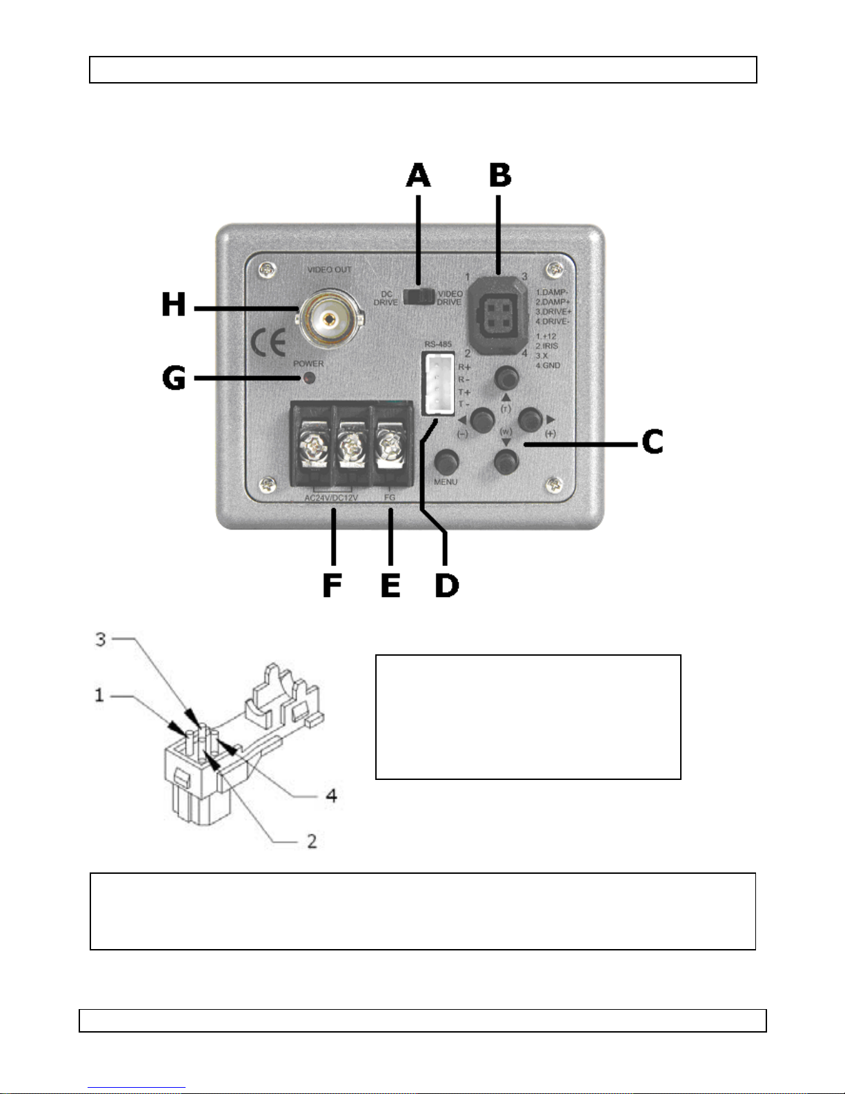
Figure 1
DC drive
1 DAMP-
2 DAMP+
3 DRIVE-
4 DRIVE+
Video drive Power
Alimentation
1 2 3 4
Video Not used GND
Vidéo Non utilisé Masse
28/05/2009 ©Velleman nv
2
Page 3
CAMSCC16
User manual
1. Introduction
To all residents of the European Union
Important environmental information about this prod uct
This symbol on the device or the package indicates that disposal
of the device after its lifecycle could harm the environment. Do
not dispose of the unit (or batteries) as unsorted municipal
waste; it should be taken to a specialized company for recycling.
This device should be returned to your distributor or to a local
recycling service. Respect the local environmental rules.
If in doubt, contact your local waste disposal authorities.
Thank you for choosing the Velleman! Please read the manual thoroughly
before bringing this device into service. If the device was damaged in transit,
don't install or use it and contact your dealer. Damage caused by disregard of
certain guidelines in this manual is not covered by the warranty and the
dealer will not accept responsibility for any ensuing defects or problems.
Content: camera | mounting bracket + screws |
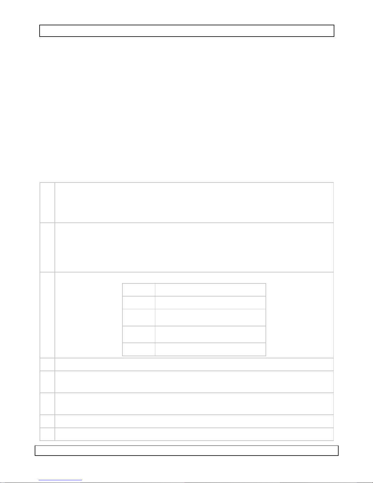
2. Safety Instructions
For indoor use only. Keep this device away from rain, moisture,
splashing and dripping liquids. Do not use in high humidity locations.
Keep the device away from children and unauthorised users.
There are no user-serviceable parts inside the device. Refer to an
authorized dealer for service and/or spare parts.
3. General Guidelines
Refer to the Velleman® Service and Quality Warranty on the last pages
of this manual.
• Protect this device from shocks and abuse. Avoid brute force when
operating the device.
• Protect the device against extreme heat and dust.
• Familiarise yourself with the functions of the device before actually using it.
• All modifications of the device are forbidden for safety reasons.
• Only use the device for its intended purpose. Using the device in an
unauthorised way will void the warranty.
28/05/2009 ©Velleman nv
3
Page 4
CAMSCC16
4. Features
• high sensitivity, low smear, high anti-blooming and high S/N ratio
• removable IR-Cut filter provides change from colour to B/W mode
automatically or manually for day and night surveillance
• RS-485/422 remote control via PELCO D&P protocol
• with built-in auto electronic shutter
• special functions via on-screen display (OSD) set-up menu
o privacy masking
o positive / negative image
o video mirror function
o digital zoom
• no lens included
5. Overview and use
Refer to the illustrations on page 2 of this manual.
A Iris Video/DC drive selector. Set to video drive when using a video driven
auto iris lens (based on brightness of the image in the video signal), or to
DC drive in case a direct driven auto iris lens is used (via a control signal
from the camera).
B Auto iris lens connector. Supplies power and control signals to the auto
iris lens. Refer to page 2 for the pin lay-out.
Note: a DC drive lens uses two coils, a driving coil (DRIVE) that
opens/closes the iris and a damping coil (DAMP) that stabilizes the
movement of the iris.
C Control buttons:
(T)/S Zoom Tele or Up (S)
(W)/T Zoom Wide or Down (T)
(+)/►
(-)/◄
Menu Enter or Exit Setup Menu
Increase Value (+)
Decrease Value (-)
D Serial connector: to connect an external keyboard.
E Signal Ground (FG): in case of a distorted signal, connecting this
terminal to earth might enhance the signal.
F Power supply: connect a 12VDC or 24VAC power supply to these
terminals (no polarity).
G Power LED: on when power is present on the terminals [F].
H Video output connector (BNC): connect the camera to a monitor (not incl.).
28/05/2009 ©Velleman nv
4
Page 5

CAMSCC16
R
6. Installation
mounting
• Mount the included mounting bracket on the top or bottom of the camera
using the 2 screws. Note that an additional mounting bracket is required
to fix the camera to the wall or ceiling.
• Connect the video output [H] to a monitor or other video device via a
75 type coaxial cable (not incl.).
• Mount a lens (not incl.) to the front of the camera.
o When using a C-mount lens, the C/CS adaptor (metal ring) must remain
in place; screw the C-mount lens clockwise into the adaptor.
o When installing a CS-mount lens, use the small hex key to loosen the
hex screws on the top and at the bottom of the C/CS adaptor (do not
remove them completely) and unscrew the adaptor counter clockwise.
Screw the CS mount lens clockwise into the camera body. Do not tighten
the hex screws too hard to avoid damage to the lens or housing.
• Set the iris Video/DC drive selector [A] to the correct position depending on
the mounted lens type.
• Connect the auto iris lens connector [B]. Refer to page 2 for the applicable
pin layout.
• Connect an external keyboard (not incl.) to the serial connector [D]. The
layout of the connector depends on the connected keyboard.
R+ Interface receive+
RS-485
RS-422
- Interface receive-
T+ Interface transmit+
T- Interface transmit-
28/05/2009 ©Velleman nv
5
Page 6
CAMSCC16
T
PELCO or compatible
0-253 for Pelco-P
CAMERA ID
1-255 for Pelco-D
PROTOCOL AUTO/PELCO
SPEED 2400/4800/9600/19200
PARITY NONE
Note: max. cable length for RS-422/RS-485 is 1.219m for a 24 gauge wire
(±0.56mm). It is recommended to use shielded twisted pair.
• Connect a suitable power supply (not incl.) to the power input terminals.
Make sure that power supply is off before connecting. Note that the camera
accepts both AC 24V and DC 12 V power sources (non-polarity).
7. Operation
• Normal display mode:
PELCO Keyboard Camera Function
OPEN Brightness +
CLOSE Brightness -
Twist Joystick clockwise or Zoom In Zoom Tele
wist Joystick counter clockwise or Zoom Out Zoom Wide
NEAR None
FAR None
Move Joystick Left None
Move Joystick Right None
Move Joystick Up None
Move Joystick Down None
Enter 95; Hold the PRESET key (approximately five
seconds) until the main menu appears on the
screen.
• OSD setup menu mode:
PELCO Keyboard Camera Function
OPEN Sub Menu Enter
CLOSE Sub Menu Exit
NEAR Cursor Up
FAR Cursor Down
Move Joystick Left Decrease (-)
Accessing OSD Main
Menu
28/05/2009 ©Velleman nv
6
Page 7

CAMSCC16
T
Move Joystick Right Increase (+)
Move Joystick Up Cursor Up
Move Joystick Down Cursor Down
Twist Joystick clockwise or Zoom In None
wist Joystick counter clockwise or Zoom Out None
Refer to PELCO Keyboard (or manufacturer) manual for more
information.
8. On Screen Display (OSD)
Main menu
• To display the setup menu, select the menu-command or press the menu
button on the back of the device.
• Use S(T)/ T(W) control buttons to select each item.
• Use ◄(-)/ ►(+) control buttons to change the data. Press and hold for
faster adjustment.
• Use MENU control button to ENTER/ EXIT the menu display.
MAIN MENU VER.xxxx
EXPOSURE
WDR
DAY/NIGHT
WHITE BALANCE
PRIVACY MASK
EFFECT
DISPLAY
COMMUNICATION
DEFAULT
EXIT
st
st
st
st
st
st
st
st
ON
st
Exposure menu
LENS TYPE
BRIGHTNESS
AGC MODE
AGC MAX
AGC ADJ
FLICKERLESS
SHUTTER SPD
DSS MAX
DEFAULT
RETURN
28/05/2009 ©Velleman nv
EXPOSURE
DC/VIDEO
16
AUTO
165
NA
NA
NA
OFF
ON
st
7
Page 8

CAMSCC16
R
• The lens type can be set to DC/VIDEO or MANUAL. When set to
DC/VIDEO, the switch [A]must be set in the correct position depending
on the mounted lens.
• Brightness range: 0~36.
• Set Automatic Gain Control (AGS) mode to AUTO or MANUAL.
• AGC MAX is only available when AGC MODE is set to AUTO. Range
0~255. When AGC MAX <165 the AE option in the DAY/NIGHT menu (see
below) becomes unavailable (NA).
• AGC ADJ is only available when AGC MODE is set to AUTO. Set fixed gain
value between 0~255.
• Set FLICKERLESS to ON to eliminate the effect of fluorescent lighting on
image quality. When set to “ON”, AGC mode automatically switches to
MANUAL.
Note: this option is not available (NA) when WDR mode is ON.
• SHUTTER SPD mode is fixed (NTSC: 1/100 and PAL: 1/120) when
FLICKERLESS mode is set to “ON”.
The SHUTTER SPD mode can be set to AUTO, NORMAL (NTSC: 1/60 and PAL:
1/50), 1/250, 1/500, 1/1000, 1/2000, 1/4000, 1/10000, 1/20000, and 1/50000.
Note: when SHUTTER SPEED is set to 1/250, 1/500, 1/1000, 1/2000,
1/4000, 1/10000, 1/20000 or 1/50000 AGC mode automatically
switches to MANUAL.
Note: this option is not available (NA) when WDR mode is ON.
• DSS MAX: Low speed shutter control, offers optimal brightness level (the
higher the value, the higher the brightness level).
• DEFAULT: return to the factory-default configuration.
RETURN: Return to previous page.
WDR menu
WD
WDR MODE
WDR LEVEL
BLC MODE
BLC LEVEL
BLC AREA
DEFAULT
RETURN
ON
96
NA
NA
NA
ON
st
• When Wide Dynamic Range (WDR) is set to ON, digital zoom will
automatically switch to x1 and BLC MODE, BLC LEVEL AND BLC AREA
switch to not available (NA).
• WDR LEVEL (0~255): the higher the value, the higher the brightness
level.
• Backlight Compensation (BLC) MODE can be set to “ON/ OFF” (when WDR
mode is OFF).
28/05/2009 ©Velleman nv
8
Page 9

CAMSCC16
T
T
• BLC LEVEL (0~15): the higher the value, the higher the backlight
compensation level. (Only when WDR mode is OFF).
• BLC AREA can be set to 7 predefined areas: (only when WDR mode is
OFF).
(1) CENTER (2)
OPS (3)
OPL (4) BOTTOMS
(5) BOTTOML (6) LEFT (7) RIGHT
DAY/NIGHT menu
DAY/NIGHT
D/N MODE
DAY→NIGHT
NIGHT→DAY
SENSOR LEVEL
FILTER DELAY
DEFAULT
RETURN
AE VALUE
SENSOR VALUE
AE
83
212
NA
NA
ON
st
???
???
• Select D/N mode: AE, SENSOR, DAY or NIGHT.
o AE: mode defined by the DAY→NIGHT and NIGHT→DAY threshold
values. Auto switches between colour and B/W.
When AGC MAX < 165, AE function is not available.
o SENSOR: auto switches between colour and B/ W according to
SENSOR LEVEL and FILTER DELAY values.
o DAY: fixed colour mode.
o NIGHT: fixed B/W mode.
• DAY→NIGHT: switch to B/W mode when AE value “DAY→NIGHT” value
(in AE mode).
28/05/2009 ©Velleman nv
9
Page 10

CAMSCC16
• NIGHT→DAY: switch to colour mode when AE value “NIGHT→DAY”
value (in AE mode).
• SENSOR LEVEL: increase the value to delay the switchover to B/W mode.
Decrease the value to switch to B/W mode faster (only available when
D/N mode is set to SENSOR).
• FILTER DELAY: set a delay time (0~15s) for switching from colour to B/W
mode in environments where rapid light condition changes occur (only
available when D/N mode is set to SENSOR.
• AE VALUE: when in D/N AE mode, the current AE value is shown.
• SENSOR VALUE: when in D/N SENSOR mode, the current SENSOR value
is shown.
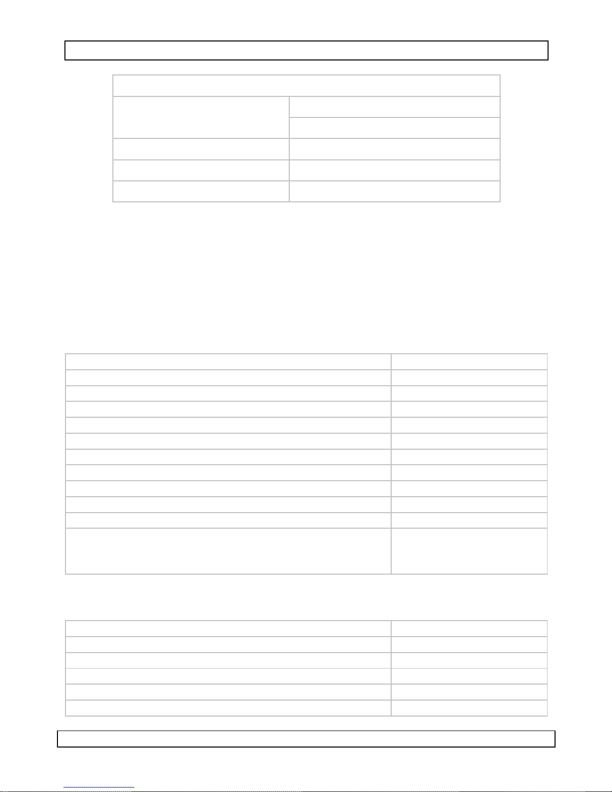
• The table shown below shows reference values. , please setup according
to the current scene.
Lens Type
DC Drive
Video Drive
Shutter
Speed
NA/ Normal On / Off 83 212
WDR
DAY→NIGHT NIGHT→DAY
Manual Iris NA On 83 195
Manual Iris
WHITE BALANCE menu
WB MODE
RED GAIN
BLUE GAIN
PUSH AUTO
DEFAULT
RETURN
Auto
Normal 83 212
Off
WHITE BALANCE
AUTO
NA
NA
NA
ON
st
83 212
• Select WB mode: AUTO, INDOOR, OUTDOOR, MANUAL, or PUSH AUTO.
• RED GAIN/ BLUE GAIN are only available when WB MODE is set to
MANUAL.
• When WB MODE is set to PUSH AUTO:
o PUSH AUTO ON: enable auto tracing white balance.
o PUSH AUTO OFF: Disable auto tracing white balance.
28/05/2009 ©Velleman nv
10
Page 11

CAMSCC16
PRIVACY MASK menu
PRIVACY MASK
AREA
MASK
START X
END X
START Y
END Y
DEFAULT
RETURN
1
OFF
20
70
20
30
ON
st
• AREA: configure a maximum of 8 mask areas.
• MASK: select “ON/ OFF” to enable or disable mask area.
• START X: horizontal start position (0~180).
• END X: horizontal end position (0~180).
• START Y: vertical start position (0~140).
• END Y: vertical end position (0~140).
EFFECT menu
EFFECT
SHARPNESS
POSI/NEGA
MIRROR
FREEZE
SYNC
V PHASE
DEFAULT
RETURN
7
POSI
OFF
OFF
INT
NA
ON
st
• SHARPNESS: set video sharpness level (0 ~15).
• POSI/ NEGA: images can be set to POSI (Positive Image) or NEGA
(Negative Image).
• MIRROR Mode: OFF / HORIZONTAL/ VERTICAL/ ROTATE.
• FREEZE: set FREEZE to “ON” to enable still field image.
• SYNC: When using a DC 12V adaptor, the sync setting is automatically
set to internal sync. When using 24 VAC power source, it can be set to
Line Lock (L/L) mode.
• V PHASE: set the desired phase (0~358) (only available when L/L mode
is selected).
28/05/2009 ©Velleman nv
11
Page 12

CAMSCC16
DISPLAY menu
DISPLAY
TITLE
TITLE DISP
TITLE POS
ID DISP
ID POS
ZOOM DISP
ZOOM POS
DEFAULT
RETURN
ON
RIGHT DOWN
ON
RIGHT DOWN
ON
LEFT DOWN
ON
st
• Insert a TITLE for the camera (max. 16 characters).
• Select the location where to display the camera TITLE, ID and ZOOM.
Possible positions are RIGHT DOWN/ LEFT UP/ RIGHT UP/ LEFT DOWN.
COMMUNICATION menu
COMMUNICATION
CAMERA ID
PROTOCOL
SPEED
PARITY
RETURN
1
AUTO
9600
NONE
st
• Refer to §6 for more information on the communication settings.
9. Technical specifications
pick-up element 1/3" Sony HR colour WDR CCD image
sensor
number of pixels 752(H) x 582(V) -PALresolution 470 TV lines
min. illumination 0.1 lux (Night / BW), 0.001 lux (DSS) /
F1.2
S/N ratio > 48dB (AGC off)
electronic shutter 1/50 to 1/100 000sec
iris mode VD / DD selectable
gamma correction 0.45
white balance automatic/indoor/outdoor/manual/
push auto
Back Light Compensation (BLC) on/off (level and area adjustable)
lens mounting C/CS
video output 1.0Vpp composite, 75 ohm
Wide Dynamic Range (WDR) on / off (level adjustable)
Infrared-Cut Removable (ICR) AE / Sensor /day / night
28/05/2009 ©Velleman nv
12
Page 13

CAMSCC16
digital zoom 3x
camera title up to 16 characters
privacy masking 8 free areas (area size adjustable)
freeze on / off
positive / negative on / off
Digital Slow Shutter (DSS) off, 2~20, 40, 80, 160 FLD
remote control RS-485 / RS-422
protocol Pelco-D and Pelco-P
synchronization system internal / external line lock
power supply DC 12V / AC 24V dual (not incl.)
power consumption max. 7W
operating temperature -10° to 50°C
dimensions 130 x 66 x 52mm
weight 520g
Use this device with original accessories only. Velleman nv cannot
be held responsible in the event of damage or injury resulted from
(incorrect) use of this device. For more info concerning this product,
please visit our website www.velleman.eu. The information in this
manual is subject to change without prior notice.
© COPYRIGHT NOTICE
This manual is copyrighted. The copyright to this manual is owned
by Velleman nv. All worldwide rights reserved. No part of this manual may
be copied, reproduced, translated or reduced to any electronic medium or
otherwise without the prior written consent of the copyright holder.
28/05/2009 ©Velleman nv
13
Page 14

CAMSCC16
NOTICE D’EMPLOI
1. Introduction
Aux résidents de l'Union européenne
Des informations environnementales importantes concernant ce
produit
Ce symbole sur l'appareil ou l'emballage indique que l’élimination d’un
appareil en fin de vie peut polluer l'environnement. Ne pas jeter
un appareil électrique ou électronique (et des piles éventuelles)
parmi les déchets municipaux non sujets au tri sélectif ; une
déchèterie traitera l’appareil en question. Renvoyer les
équipements usagés à votre fournisseur ou à un service de
recyclage local. Il convient de respecter la réglementation locale
relative à la protection de l’environnement.
En cas de questions, contacter les autorités locale s pour élimination.
Nous vous remercions de votre achat ! Lire la présente notice attentivement
avant la mise en service de l’appareil. Si l’appareil a été endommagé
pendant le transport, ne pas l’installer et consulter votre revendeur. La
garantie ne s’applique pas aux dommages survenus en négligeant certaines
directives de cette notice et votre revendeur déclinera toute responsabilité
pour les problèmes et les défauts qui en résultent.
Contenu : caméra | étrier de montage + accessoires de fixation |
2. Consignes de sécurité
Pour usage à l’intérieur uniquement. Protéger contre la pluie,
l’humidité et les projections d’eau. Ne pas employer dans un endroit
humide.
Garder hors de la portée des enfants et des personnes non
autorisées.
Il n’y a aucune pièce maintenable par l’utilisateur. Commander des
pièces de rechange éventuelles chez votre revendeur.
3. Directives générales
Se reporter à la garantie de service et de qualité Velleman® en fin de
notice.
• Protéger contre les chocs et traiter la caméra avec circonspection pendant
l’installation et l’opération.
• Tenir à l’écart de la poussière et des températures extrêmes.
• Se familiariser avec le fonctionnement avant l’emploi.
• Toute modification est interdite pour des raisons de sécurité.
28/05/2009 ©Velleman nv
14
Page 15

CAMSCC16
• N’utiliser qu’à sa fonction prévue. Un usage impropre annule d'office la
garantie.
4. Caractéristiques
• haute sensibilité lumineuse, low-smear, excellent anti-blooming et
rapport S/B élevé
• filtre IR-cut amovible : commutation automatique ou manuelle d’une
image couleur vers N/B pour la surveillance diurne ou nocturne
• télécommande RS-485/422 via le protocole PELCO D&P
• obturateur électronique automatique intégré
• fonctions spéciale depuis menu à l'écran
o masquage
o image positive/négative
o fonction d'inversion de l'image
o zoom numérique
• objectif non inclus
5. Description
Se référer aux illustrations à la page 2 de cette notice.
A Sélecteur objectif VIDEO DRIVE/DC DRIVE. Sélectionner VIDEO DRIVE
avec un objectif à iris automatique piloté par vidéo (luminosité de ‘image
dans le signal vidéo). Sélectionner DC DRIVE avec un objectif à iris
automatique piloté par DC (via le signal de contrôle de la caméra).
B Prise d’alimentation et de signal pour l’objectif à iris automatique. Se
référer à la page 2 pour la disposition des broches.
Remarque : L’objectif à iris automatique piloté par DC utilise 2 bobines,
c.à.d. une bobine d’entraînement (DRIVE) qui ouvre/ferme l’iris, et une
bobine d’amortissement (DAMP) qui stabilise le mouvement de l’iris.
C Boutons de commande :
(T)/S zoom avant ou S
(W)/T zoom arrière ou T
(+)/►
(-)/◄
MENU accéder/quitter menu
augmenter la valeur (+)
diminuer la valeur (-)
D Connexion sérielle pour clavier externe.
E Prise de terre (FG) : connecter cette borne à la terre en cas de
distorsion du signal.
28/05/2009 ©Velleman nv
15
Page 16

CAMSCC16
R
F Bornes de connexion de l’alimentation 12 VCC ou 24VCA (aucune
polarité).
G DEL de puissance : S’allume lorsque la caméra est alimentée [F].
H Connexion de sortie vidéo (BNC) vers un moniteur (non inclus).
6. Installation
Montage
• Fixer l’étrier de montage sur la caméra à l’aide des 2 vis. Le montage
mural ou au plafond de la caméra nécessite un étrier supplémentaire.
• Connecter la sortie vidéo [H] à un moniteur ou autre appareil vidéo à
l’aide d’un câble coaxial de 75 (non inclus).
• Installer l’objectif (non inclus) à l’avant de la caméra.
o Objectif type C-mount : Ne pas retirer l’adaptateur C/CS (anneau
métallique). Installer l’objectif type C-mount.
o Objectif type CS-mount : Desserrer les vis Allen de l’adaptateur C/CS
sans pour autant les retirer complètement. Desserrer l’adaptateur C/CS
et installer un adaptateur CS. Ne pas serrer excessivement les vis Allen
afin de ne pas endommager l’objectif.
• Sélectionner VIDEO DRIVE/DC DRIVE [A] en fonction de l’objectif utilisé.
• Connecter la prise d’alimentation et de signal pour l’objectif à iris
automatique [B]. Se référer à la page 2 pour la disposition des broches.
• Connecter un clavier externe (non inclus) à la prise [D]. la disposition des
broches dépend du type de clavier.
R+ Interface réception+
RS-485
RS-422
- Interface réception -
T+ Interface transmission+
T- Interface transmission -
28/05/2009 ©Velleman nv
16
Page 17

CAMSCC16
T
T
PELCO ou compatible
0~253 pour protocole Pelco-P
ID DE LA CAMÉRA
1~255 pour protocole Pelco-D
PROTOCOLE AUTO/PELCO
VITESSE 2400/4800/9600/19200
PARITÉ /
Remarque : Longueur max. du câble pour RS-422/RS-485 : 1.219 m (24AWG
ou ± 0,56 mm). Utiliser un câble à paires torsadées blindé.
• Connecter une alimentation 12 VCC ou 24 VCA (pas de polarité, non
incluse). Veiller à ce que l’alimentation soit éteinte avant de la connecter à
la caméra.
7. Emploi
• Affichage normal
Clavier PELCO Fonction de caméra
OPEN Luminosité +
CLOSE Luminosité -
Tourner la manette vers la droite ou TELE Zoom avant
ourner la manette vers la gauche ou WIDE Zoom arrière
NEAR /
FAR /
Déplacer la manette vers la gauche /
Déplacer la manette vers la droite /
Déplacer la manette vers le haut /
Déplacer la manette vers le bas /
Saisir 95 ; maintenir enfoncé PRESET pendant 5 s Accès au menu OSD
• OSD setup menu mode
Clavier PELCO Fonction de caméra
Déplacer la manette vers la gauche Diminuer (-)
Déplacer la manette vers la droite Augmenter (+)
Déplacer la manette vers le haut Curseur S
Déplacer la manette vers le bas Curseur T
Tourner la manette vers la droite ou TELE /
ourner la manette vers la gauche ou WIDE /
Se référer à la notice d’emploi du clavier PELCO pour plus d’information.
28/05/2009 ©Velleman nv
OPEN Accès sous-menu
CLOSE Quitter sous-menu
NEAR Curseur S
FAR Curseur T
17
Page 18

CAMSCC16
8. Menu à l’écran OSD
Menu principal
• Accéder au menu en enfonçant le bouton de commande MENU.
• Sélectionner un sous-menu avec les boutons de commande S(T)/T(W).
• Modifier la valeur avec les boutons de commande ◄(-)/ ►(+).
• Quitter le menu en enfonçant le bouton de commande MENU.
MAIN MENU VER.xxxx
EXPOSURE
WDR
DAY/NIGHT
WHITE BALANCE
PRIVACY MASK
EFFECT
DISPLAY
COMMUNICATION
DEFAULT
EXIT
st
st
st
st
st
st
st
st
ON
st
Menu EXPOSURE
EXPOSURE
LENS TYPE
BRIGHTNESS
AGC MODE
AGC MAX
AGC ADJ
FLICKERLESS
SHUTTER SPD
DSS MAX
DEFAULT
RETURN
DC/VIDEO
16
AUTO
165
NA
NA
NA
OFF
ON
st
• Sélectionner le type d’objectif DC/VIDEO ou MANUAL. Sélectionner VIDEO
DRIVE/DC DRIVE [A] en fonction de l’objectif utilisé.
• Plage de sélection BRIGHTNESS (luminosité) : 0~36.
• Sélectionner l’option AUTO ou MANUAL pour le sous-menu AGC MODE
(Automatic Gain Control).
• AGC MAX n’est disponible que lorsqu’AGC MODE est en mode AUTO.
Plage de sélection : 0~255. L’option AE dans le sous-menu DAY/NIGHT
(voir ci-dessous) n’est pas disponible (NA) lorsqu’AGC MAX <165.
28/05/2009 ©Velleman nv
18
Page 19

CAMSCC16
R
• AGC ADJ n’est disponible que lorsqu’AGC MODE est en mode AUTO. Plage
de sélection : 0~255.
• Activer l’option FLICKERLESS (ON) pour éliminer l’effet d’un éclairage
fluorescent sur l’image. L’option AGC MODE commute automatiquement
en mode MANUAL lors de l’activation de l’option FLICKERLESS.
Remarque : Cette option n’est pas disponible (NA) lorsque l’option WDR
MODE est activé (ON).
• L’option SHUTTER SPD est fixée (NTSC : 1/100 et PAL : 1/120) lorsque
FLICKERLESS est activé (ON).
Sélectionner l’option AUTO, NORMAL (NTSC : 1/60 et PAL : 1/50), 1/250,
1/500, 1/1000, 1/2000, 1/4000, 1/10000, 1/20000, et 1/50000.
Remarque : L’option AGC MODE commute automatiquement en mode
MANUAL lorsque SHUTTER SPEED est configurée comme 1/250, 1/500,
1/1000, 1/2000, 1/4000, 1/10000, 1/20000 ou 1/50000.
Remarque : Cette option n’est pas disponible (NA) lorsque WDR MODE est
activé (ON).
• DSS MAX : Permet une accumulation plus importante de lumière dans
l’imageur.
• DEFAULT : Rétablissement de la configuration d’usine.
RETURN : Retour vers la page précédente.
Menu WDR
WD
WDR MODE
WDR LEVEL
BLC MODE
BLC LEVEL
BLC AREA
DEFAULT
RETURN
ON
96
NA
NA
NA
ON
st
• Le zoom numérique commute automatiquement en mode x1 et les
fonctions BLC MODE, BLC LEVEL et BLC AREA ne sont pas disponibles
(NA) lorsque WDR MODE est activé (ON).
• WDR LEVEL (0~255) : La luminosité augmente avec la valeur.
• BLC MODE (compensation de contrejour) : Sélectionner ON ou OFF
(lorsque WDR MODE est désactivé (OFF).
• BLC LEVEL (0~15) : Le niveau de compensation de contrejour augmente
avec la valeur (lorsque WDR MODE est désactivé (OFF).
• BLC AREA : Sélection de 7 zones prédéfinies (lorsque WDR MODE est
désactivé (OFF) :
28/05/2009 ©Velleman nv
19
Page 20

CAMSCC16
(1) CENTER (2) TOPS (3) TOPL (4) BOTTOMS
(5) BOTTOML (6) LEFT (7) RIGHT
Menu DAY/NIGHT
DAY/NIGHT
D/N MODE
DAY→NIGHT
NIGHT→DAY
SENSOR LEVEL
FILTER DELAY
DEFAULT
RETURN
AE VALUE
SENSOR VALUE
AE
83
212
NA
NA
ON
st
???
???
• Sélectionner D/N MODE : AE, SENSOR, DAY ou NIGHT.
o AE : Mode défini par les valeurs DAY→NIGHT et NIGHT→DAY.
Commute automatiquement entre une image couleur ou noir et blanc.
Cette option n’est pas disponible lorsqu’AGC MAX <165.
o SENSOR : Commute automatiquement entre une image couleur ou
noir et blanc selon les valeurs SENSOR LEVEL et FILTER DELAY.
o DAY : Image couleur fixe.
o NIGHT : Image noir et blanc fixe.
• DAY→NIGHT : L’image commute vers une image noir et blanc lorsque la
valeur AE la valeur DAY→NIGHT en mode AE.
28/05/2009 ©Velleman nv
20
Page 21

CAMSCC16
• NIGHT→DAY : L’image commute vers une image couleur lorsque la valeur
AE la valeur DAY→NIGHT en mode AE.
• SENSOR LEVEL : Augmenter la valeur pour commuter moins rapidement
vers une image noir et blanc ; diminuer la valeur pour commuter plus
rapidement vers une image noir et blanc (uniquement disponible lorsque
l’option D/N MODE est en mode SENSOR).
• FILTER DELAY : Sélectionner le délai de commutation (0~15s) d’une
image couleur vers une image noir et blanc dans un environnement avec
des changements rapides de luminosité (uniquement disponible lorsque
l’option D/N MODE est en mode SENSOR).
• AE VALUE : Valeur AE en mode D/N MODE, option AE activée.
• SENSOR VALUE : Valeur SENSOR en mode D/N MODE, option SENSOR
activée.
• Consulter la table des valeurs de référence ci-dessous :
Type
d’objectif
DC DRIVE
VIDEO DRIVE
Iris manuel NA On 83 195
Iris manuel
Menu WHITE BALANCE
WB MODE
RED GAIN
BLUE GAIN
PUSH AUTO
DEFAULT
RETURN
Vitesse de
l’obturateur
NA/Normal On/Off 83 212
Auto
Normal 83 212
WHITE BALANCE
WDR
Off
AUTO
NA
NA
NA
ON
st
DAY→NIGHT NIGHT→DAY
83 212
• Sélectionner WB MODE : AUTO, INDOOR, OUTDOOR, MANUAL ou PUSH
AUTO.
• Les options RED GAIN/ BLUE GAIN ne sont disponibles que lorsque
l’option WB MODE est en mode MANUAL.
• Option WB MODE en mode PUSH AUTO :
o PUSH AUTO ON : Activation de la fonction ATW.
o PUSH AUTO OFF : Désactivation de la fonction ATW.
28/05/2009 ©Velleman nv
21
Page 22

CAMSCC16
Menu PRIVACY MASK
PRIVACY MASK
AREA
MASK
START X
END X
START Y
END Y
DEFAULT
RETURN
1
OFF
20
70
20
30
ON
st
• AREA : Configuration d’un maximum de 8 zones de masquage.
• MASK : Activation/désactivation (ON/OFF) du masquage.
• START X : Position de départ horizontale (0~180).
• END X : Position d’arrêt horizontale (0~180).
• START Y : Position de départ verticale (0~140).
• END Y : Position d’arrêt verticale (0~140).
Menu EFFECT
EFFECT
SHARPNESS
POSI/NEGA
MIRROR
FREEZE
SYNC
V PHASE
DEFAULT
RETURN
7
POSI
OFF
OFF
INT
NA
ON
st
• SHARPNESS : Réglage du piqué de l’image (0 ~15).
• POSI/ NEGA : Affichage d’une image positive (POSI) ou négative (NEGA).
• MIRROR : OFF/HORIZONTAL/VERTICAL/ROTATE.
• FREEZE : Sélectionner ON pour obtenir une image fixe.
• SYNC : Sélection automatique de la synchronisation interne lors de
l’utilisation d’une alimentation 12 VCC ou du mode L/L (Line Lock) lors de
l’utilisation d’une alimentation 24 VCA.
• V PHASE : Sélectionner la phase (0~358) (uniquement disponible lorsque
le mode L/L est sélectionné).
28/05/2009 ©Velleman nv
22
Page 23

CAMSCC16
r
T
Menu DISPLAY
DISPLAY
TITLE
TITLE DISP
TITLE POS
ID DISP
ID POS
ZOOM DISP
ZOOM POS
DEFAULT
RETURN
ON
RIGHT DOWN
ON
RIGHT DOWN
ON
LEFT DOWN
ON
st
• Attribution d’un nom à la caméra (max. 16 caractères).
• Sélectionner l’endroit d’affichage du nom de la caméra, de l’ID et du
ZOOM (RIGHT DOWN/LEFT UP/RIGHT UP/LEFT DOWN).
Menu COMMUNICATION
COMMUNICATION
CAMERA ID
PROTOCOL
SPEED
PARITY
RETURN
1
AUTO
9600
NONE
st
• Se reporter au paragraphe §6 pour plus d’information concernant la
configuration.
9. Spécifications techniques
capteur capteur d'image CCD couleur 1/3" de
Sony
nombre de pixels 752(H) x 582(V) -PAL-
ésolution 470 lignes
éclairement min. 0,1 lux (nuit//N/B), 0,001 lux
(DSS)/F1,2
rapport S/B > 48 dB (AGC éteint)
obturateur électronique 1/50 ~ 1/100 000 sec
mode iris VD/DD sélectionnable
correction gamma 0,45
balance des blancs automatique/intérieur/extérieur/manuel
/auto
compensation de contrejour(BLC) marche/arrêt
montage de l’objectif C/CS
sortie vidéo 1,0 Vpp composite, 75
Wide Dynamic Range (WDR) marche/arrêt (réglable)
28/05/2009 ©Velleman nv
23
V
Page 24

CAMSCC16
Infrared-Cut Removable (ICR) AE/capteur/jour/nuit
zoom numérique 3x
nom de la caméra jusqu’à 16 caractères
masquage 8 zones (taille réglable)
image fixe marche/arrêt
image positive/négative marche/arrêt
Digital Slow Shutter (DSS) arrêt, 2~20, 40, 80, 160 FLD
télécommande RS-485/RS-422
protocole Pelco-D et Pelco-P
synchronisation interne/externe
alimentation 12 VCC/24 VCA (non incl.)
consommation max. 7 W
température de service -10° ~ 50°C
dimensions 130 x 66 x 52 mm
poids 520 g
N’employer cet appareil qu’avec des accessoires d’origine. SA
Velleman ne sera aucunement responsable de dommages ou lésions
survenus à un usage (incorrect) de cet appareil. Pour plus
d’information concernant cet article, visitez notre site web
www.velleman.eu. Toutes les informations présentées dans cette
notice peuvent être modifiées sans notification préalable.
© DROITS D’AUTEUR
SA Velleman est l’ayant droit des droits d’auteur pour cette notice.
Tous droits mondiaux réservés. Toute reproduction, traduction, copie ou
diffusion, intégrale ou partielle, du contenu de cette notice par quelque
procédé ou sur tout support électronique que se soit est interdite sans
l’accord préalable écrit de l’ayant droit.
28/05/2009 ©Velleman nv
24
Page 25

Velleman® Service and Quality Warranty
Velleman® has over 35 years of experience in
the electronics world and distributes its
products in more than 85 countries.
All our products fulfil strict quality
requirements and legal stipulations in the EU.
In order to ensure the quality, our products
regularly go through an extra quality check,
both by an internal quality department and by
specialized external organisations. If, all
precautionary measures notwithstanding,
problems should occur, please make appeal to
our warranty (see guarantee conditions).
General War r anty Conditions Concer ning
Consumer Products (for EU):
• All consumer products are subject to a 24month warranty on production flaws and
defective material as from the original date of
purchase.
• Velleman® can decide to replace an article
with an equivalent article, or to refund the
retail value totally or partially when the
complaint is valid and a free repair or
replacement of the article is impossible, or if
the expenses are out of proportion.
You will be delivered a replacing article or a
refund at the value of 100% of the purchase
price in case of a flaw occurred in the first year
after the date of purchase and delivery, or a
replacing article at 50% of the purchase price
or a refund at the value of 50% of the retail
value in case of a flaw occurred in the second
year after the date of purchase and delivery.
• Not covered by warranty:
- all direct or indirect damage caused after
delivery to the article (e.g. by oxidation,
shocks, falls, dust, dirt, humidity...), and by
the article, as well as its contents (e.g. data
loss), compensation for loss of profits;
- frequently replaced consumable goods, parts
or accessories such as batteries, lamps, rubber
parts, drive belts... (unlimited list);
- flaws resulting from fire, water damage,
lightning, accident, natural disaster, etc. …;
- flaws caused deliberately, negligently or
resulting from improper handling, negligent
maintenance, abusive use or use contrary to
the manufacturer’s instructions;
- damage caused by a commercial, professional
or collective use of the article (the warranty
validity will be reduced to six (6) months when
the article is used professionally);
- damage resulting from an inappropriate
packing and shipping of the article;
- all damage caused by modification, repair or
alteration performed by a third party without
written permission by Velleman®.
• Articles to be repaired must be delivered to
your Velleman® dealer, solidly packed
(preferably in the original packaging), and be
completed with the original receipt of purchase
and a clear flaw description.
• Hint: In order to save on cost and time,
please reread the manual and check if the flaw
is caused by obvious causes prior to presenting
the article for repair. Note that returning a
non-defective article can also involve handling
costs.
• Repairs occurring after warranty expiration
are subject to shipping costs.
• The above conditions are without prejudice to
all commercial warranties.
The above enumeration is subject to
modification according to the article (see
article’s manual).
Garantie de service et de qualité
Velleman®
Velleman® jouit d’une expérience de plus de
35 ans dans le monde de l’électronique avec
une distribution dans plus de 85 pays.
Tous nos produits répondent à des exigences
de qualité rigoureuses et à des dispositions
légales en vigueur dans l’UE. Afin de garantir la
qualité, nous soumettons régulièrement nos
produits à des contrôles de qualité
supplémentaires, tant par notre propre service
qualité que par un service qualité externe.
Dans le cas improbable d’un défaut malgré
toutes les précautions, il est possible
d’invoquer notre garantie (voir les conditions
de garantie).
Conditions générales concer na nt la
garantie sur les produits grand public
(pour l’UE) :
• tout produit grand public est garanti 24 mois
contre tout vice de production ou de matériaux
à dater du jour d’acquisition effective ;
• si la plainte est justifiée et que la réparation
ou le remplacement d’un article est jugé
impossible, ou lorsque les coûts s’avèrent
disproportionnés, Velleman® s’autorise à
remplacer ledit article par un article équivalent
ou à rembourser la totalité ou une partie du
prix d’achat. Le cas échéant, il vous sera
consenti un article de remplacement ou le
remboursement complet du prix d’achat lors
d’un défaut dans un délai de 1 an après l’achat
et la livraison, ou un article de remplacement
moyennant 50% du prix d’achat ou le
remboursement de 50% du prix d’achat lors
d’un défaut après 1 à 2 ans.
• sont par conséquent exclus :
Page 26

- tout dommage direct ou indirect survenu à
l’article après livraison (p.ex. dommage lié à
l’oxydation, choc, chute, poussière, sable,
impureté…) et provoqué par l’appareil, ainsi
que son contenu (p.ex. perte de données) et
une indemnisation éventuelle pour perte de
revenus ;
- tout bien de consommation ou accessoire, ou
pièce qui nécessite un remplacement régulier
comme p.ex. piles, ampoules, pièces en
caoutchouc, courroies… (liste illimitée) ;
- tout dommage qui résulte d’un incendie, de la
foudre, d’un accident, d’une catastrophe
naturelle, etc. ;
- out dommage provoqué par une négligence,
volontaire ou non, une utilisation ou un
entretien incorrects, ou une utilisation de
l’appareil contraire aux prescriptions du
fabricant ;
- tout dommage à cause d’une utilisation
commerciale, professionnelle ou collective de
l’appareil (la période de garantie sera réduite à
6 mois lors d’une utilisation professionnelle) ;
- tout dommage à l’appareil qui résulte d’une
utilisation incorrecte ou différente que celle
pour laquelle il a été initialement prévu comme
décrit dans la notice ;
- tout dommage engendré par un retour de
l’appareil emballé dans un conditionnement
non ou insuffisamment protégé.
- toute réparation ou modification effectuée par
une tierce personne sans l’autorisation explicite
de SA Velleman® ; - frais de transport de et
vers Velleman® si l’appareil n’est plus couvert
sous la garantie.
• toute réparation sera fournie par l’endroit de
l’achat. L’appareil doit nécessairement être
accompagné du bon d’achat d’origine et être
dûment conditionné (de préférence dans
l’emballage d’origine avec mention du défaut) ;
• tuyau : il est conseillé de consulter la notice
et de contrôler câbles, piles, etc. avant de
retourner l’appareil. Un appareil retourné jugé
défectueux qui s’avère en bon état de marche
pourra faire l’objet d’une note de frais à charge
du consommateur ;
• une réparation effectuée en-dehors de la
période de garantie fera l’objet de frais de
transport ;
• toute garantie commerciale ne porte pas
atteinte aux conditions susmentionnées.
La liste susmentionnée p eut être sujette à
une complémentation selon le type de
l’article et être mentionnée dans la notice
d’emploi.
 Loading...