

Page 1

C
W
D
C
ACÁ
D
U
SGENOMA
B
E
AMI
P
IRELE
S
RAADL
O
MÉRA
MARA
RAHTL
O
ER MAN
BRUIKE
R
TICE D’
E
NUAL D
DIENUN
5N
S IP C
O
ZE IP
K
COULE
U
IP INA
L
SE IP-
F
UAL
SHAND
L
MPLOI
EL USUA
R
GSANLEI
T
LOUR
C
LEURE
R IP S
A
MBR
I
ARBK
A
EIDING
IO
T
UNG
AMER
A
NCAME
R
NS FI
L
CA A C
O
MERA
3
21
40
59
78
A
LOR
Page 2

CAMIP5N
V. 02 – 22/05/2012 2 ©Velleman nv
© COPYRIGHT NOTICE
The copyright to this manual is owned by Velleman nv. All worldwide rights reserved.
No part of this manual may be copied, reproduced, translated or reduced to any electronic medium or otherwise
without the prior written consent of the copyright holder.
© AUTEURSRECHT
Velleman nv heeft het auteursrecht voor deze handleiding. Alle wereldwijde rechten voorbehouden.
Het is niet toegestaan om deze handleiding of gedeelten ervan over te nemen, te kopiëren, te vertalen, te
bewerken en op te slaan op een elektronisch medium zonder voorafgaande schriftelijke toestemming van de
rechthebbende.
© DROITS D’AUTEUR
SA Velleman est l’ayant droit des droits d’auteur pour cette notice. Tous droits mondiaux réservés.
Toute reproduction, traduction, copie ou diffusion, intégrale ou partielle, du contenu de cette notice par quelque
procédé ou sur tout support électronique que se soit est interdite sans l’accord préalable écrit de l’ayant droit.
© DERECHOS DE AUTOR
Velleman NV dispone de los derechos de autor para este manual del usuario. Todos los derechos
mundiales reservados.
Está estrictamente prohibido reproducir, traducir, copiar, editar y guardar este manual del usuario o partes de
ello sin previo permiso escrito del derecho habiente.
© URHEBERRECHT
Velleman NV besitzt das Urheberrecht für diese Bedienungsanleitung. Alle weltweiten Rechte
vorbehalten.
Ohne vorherige schriftliche Genehmigung des Urhebers ist es nicht gestattet, diese Bedienungsanleitung ganz
oder in Teilen zu reproduzieren, zu kopieren, zu übersetzen, zu bearbeiten oder zu speichern.
Page 3
V.
1
.
T
oIm
Th
th
e
2
.3.
Re
•
•
•
•
•
4
.
•
•
•
•
•
•
5
.
Re
1
2
3
4
5
6
02 – 22/05/2
Intr
o
all reside
n
portant e
n
This
har
m
shou
distri
If in
ank you for
device wa
s
Safe
t
Ke
e
Ri
s
ele
c
D
O
to
a
Gen
e
fer to the V
e
Familiaris
e
All modific
Only use t
warranty.
Damage c
a
dealer will
DO NOT
u
Feat
u
easy insta
l
remote Pa
secured W
11 IR LED
s
embedded
motion de
t
Ove
r
fer to the ill
light sen
IR LED (
speaker
lens
microph
o
Wi-Fi an
t
012
duction
ts of the
E
vironmen
t
symbol on t
h
the enviro
n
ld be taken
t
butor or to
a
doubt, co
n
choosing V
e
damaged i
n
y Instr
u
p the devic
e
k of electr
o
c
troshocks.
NOT disas
s
n authoriz
e
ral Gui
d
lleman®
S
Indoor
u
Keep thi
s
Protect t
yourself wi
ations of th
e
he device fo
used by di
s
not accept
r
se this pro
d
res
lation proc
e
n/Tilt contr
o
i-Fi and wir
e
for night v
microphon
e
ection alert
view
ustrations o
sor
11x)
ne
enna
uropean U
n
al informa
t
e device o
r
ment. Do n
o a speciali
local recy
c
tact your l
lleman! Ple
a
transit, d
o
ctions
away fro
m
shock wh
e
Do not ope
n
emble or o
p
d dealer for
elines
ervice an
d
se only.
K
device aw
a
his device f
r
th the funct
i
device are
r its intend
e
regard of c
e
esponsibilit
y
uct to viola
t
dure
l
d LAN conn
ision
and speak
e
via email o
r
n page 2 of
USE
ion
ion about
t
the packag
ot dispose
o
zed compan
ling service
.
ocal waste
se read th
e
n't install o
r
children a
n
n opening t
the housin
g
en the cov
e
service and
Quality
W
eep this de
v
y from dus
t
om shocks
a
ons of the
d
forbidden f
o
d purpose.
U
rtain guidel
for any en
e privacy la
ection
r
upload im
a
this manual
CAMIP5N
3
R MA
N
t
his produ
c
e indicates
t
f the unit (
o
y for recycli
Respect th
e
disposal a
manual th
o
use it and
c
d unauthori
he cover. T
o
yourself.
H
r. There ar
e
/or spare p
a
arranty on
ice away fo
and extre
m
nd abuse.
A
evice befor
e
r safety re
a
sing the d
e
ines in this
m
suing defec
t
ws or perfo
r
ge to FTP.
.
7
a8 a
9
8
10
p
11
n
12
5
UAL
t
hat disposa
r batteries)
ng. This de
v
local envi
r
uthorities.
roughly bef
o
ontact you
r
sed users.
uching live
ave the de
v
no user-se
rts.
the last pa
g
m rain, mo
i
e heat.
void brute
f
actually u
s
sons.
vice in an u
anual is n
o
s or proble
m
m other ille
g
udio outpu
t
udio input
P8C netwo
r
ower LED
etwork LE
D
V DC input
l of the devi
as unsorte
d
ice should
b
onmental r
u
re bringing
dealer.
wires can c
a
ice repaire
d
rviceable pa
es of this
m
sture, splas
orce when
o
ing it.
nauthorised
t covered b
s.
al activitie
s
k jack (RJ4
5
jack (2A)
ce after its l
municipal
w
e returned
t
les.
this device
use life-thr
e
by qualifie
d
rts inside t
h
anual.
hing and dr
i
perating th
way will vo
y the warra
n
.
)
©Vellema
n
ifecycle cou
l
aste; it
o your
into service
atening
personnel.
e device. R
e
pping liquid
e device.
id the
ty and the
nv
d
. If
fer
s.
Page 4

CAMIP5N
V. 02 – 22/05/2012 4 ©Velleman nv
6. Hardware installation and operation
1. Choose a location for the camera, keeping following guidelines in mind:
o Do not install the camera in locations where extremely high or low temperatures or excessive vibrations
may occur.
o Avoid mounting the camera near high electro-magnetic fields.
o Do not aim the camera at the sun or other extremely bright objects.
2. The camera can be used free standing or in combination with the included mounting bracket. When the
mounting bracket is used, attach it to the wall or ceiling using the 2 included screws. Place the CAMIP5N
on top and secure it with the centre screw. Determine the desired angle and tighten the joint screws.
3. Connect the antenna [6] to the antenna connector and/or connect a network cable (included) to the 8P8C
(RJ45) jack [9].
Note: it is possible to connect the camera straight to the 8P8C (RJ45) port of a computer. In this case a
crossed cable (not incl.) should be used and network settings must be configured manually.
4. An external microphone (not incl.) can be connected to the audio input [8].
5. When desired, an external speaker system can be connected to the audio output [7].
6. Plug the DC connector of the power adaptor into the 5VDC input jack [12]. Only use the included adaptor
or one with the same specifications.
7. Plug the adaptor into a suitable mains outlet (100~240V AC/50~60Hz).
Notes:
• It takes about 30s for the camera to initialise.
• During initialisation the camera will start moving to test the pan/tilt functionality.
• If the image appears out of focus, turn the lens [4] to adjust.
7. Software installation
Insert the included CD-ROM into a suitable computer system (not incl.).
System requirements: CPU ≥ 2.06 GHz / memory ≥ 256MB / network ≥ 10 MB / video card ≥ 64MB memory /
recommended OS: Windows 2000 or XP / Mac.
Windows
1. Locate the software installer IPCamSetup.exe and double-click it.
Page 5
CAMIP5N
V. 02 – 22/05/2012 5 ©Velleman nv
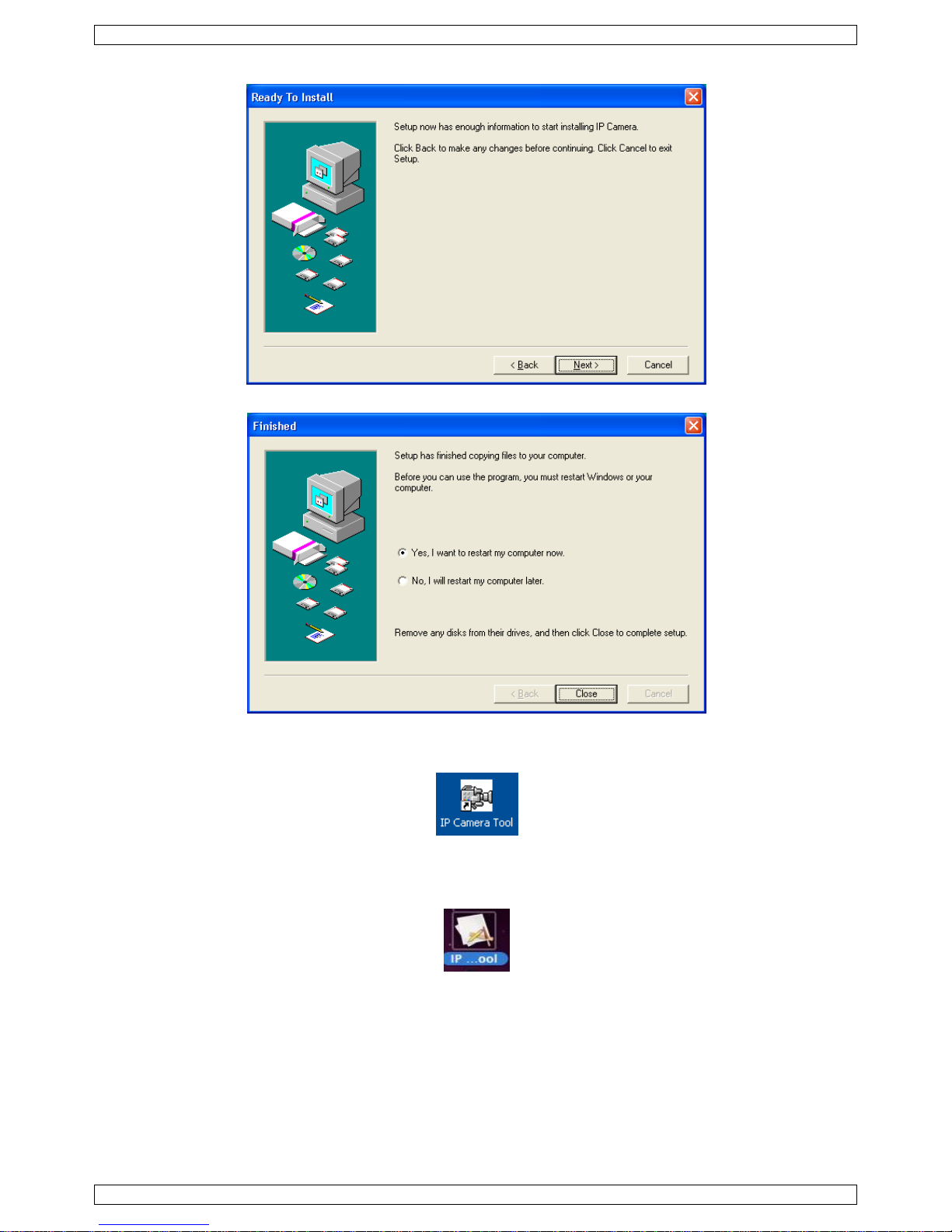
2. Follow the instructions on the screen. Click Next to start the software installation.
3. Click Next again.
4. To finish software installation, the computer must be restarted. Select Yes I want to restart my
computer now and click Close.
After rebooting, the IP Camera Tool icon appears on the desktop.
Mac
1. Locate and open the folder “For Mac”.
2. Open the folder “IP camera Tool” and copy the tool to your Mac to use it.
8. Software set-up
Make sure all connections are properly made (see also §6) and double-click the IP Camera Tool icon to start
the software.
8.1 IP Camera Tool
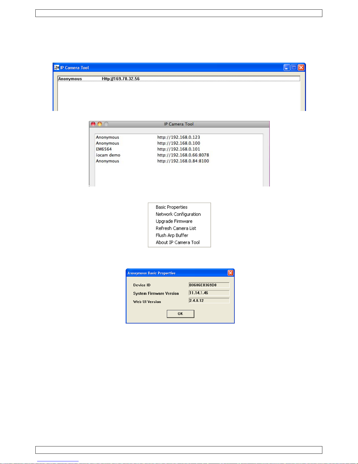
1. The software starts searching for cameras over the LAN. Three situations can occur:
o No cameras are found on the LAN. If after 1 minute the software does not detect any cameras, check all
cabling of the system and make sure the camera is powered.
o Cameras are found and listed (see image below).
Page 6

CAMIP5N
V. 02 – 22/05/2012 6 ©Velleman nv
o Cameras are found but are not on the same subnet as the PC. The message Subnet doesn’t match,
dbclick to change appears. Change the subnet settings via the network configuration menu (see
further).
Note: make sure DHCP is enabled in the router and MAC address filter is disabled. When problems remain,
disable any active firewall or antivirus and try again.
Windows:
Mac:
2. Open the options menu by right-clicking a listed camera.
Note: only when the camera is fully initialised all options become visible.
Basic properties
Shows some general information about the camera:
Page 7

CAMIP5N
V. 02 – 22/05/2012 7 ©Velleman nv
Network Configuration
View/change the network settings of the camera:
• When connected to a DHCP router, check the Obtain IP from DHCP server checkbox, otherwise uncheck
it and fill in the data manually.
• In case of a subnet mismatch, change the IP-address or subnet mask.
• When in doubt about the network settings, contact a qualified network administrator.
Upgrade firmware
Only use this option when problems with the current version are noticed. Do not upgrade if the camera works
fine.
Caution: when the upgrade process is interrupted or a wrong version is installed the camera might not work
anymore.
The administrator’s login and password are required.
Note: default administrator login is admin without a password.
Refresh Camera List
Use this option to update the camera list, e.g. when a new camera is added to the network.
Flush ARP Buffer
When both a wireless and wired connection to a camera exists, a problem with the ARP (Address Resolution
Protocol) may arise resulting in the camera not being accessible via the browser. In this case the ARP buffer
should be cleared.
About IP Camera Tool
Shows some extra information about the camera tool.
Page 8
CAMIP5N
V. 02 – 22/05/2012 8 ©Velleman nv
8.2 Camera login
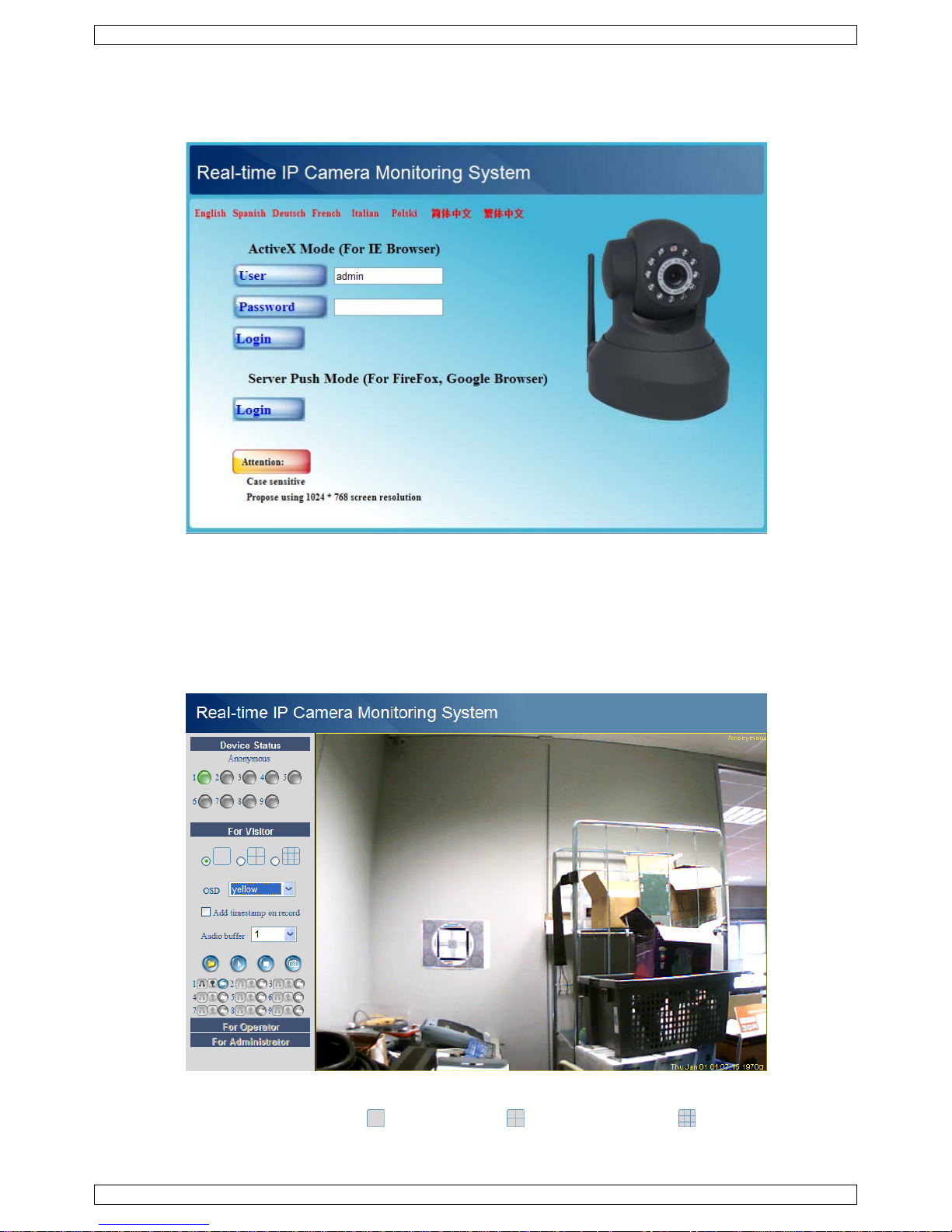
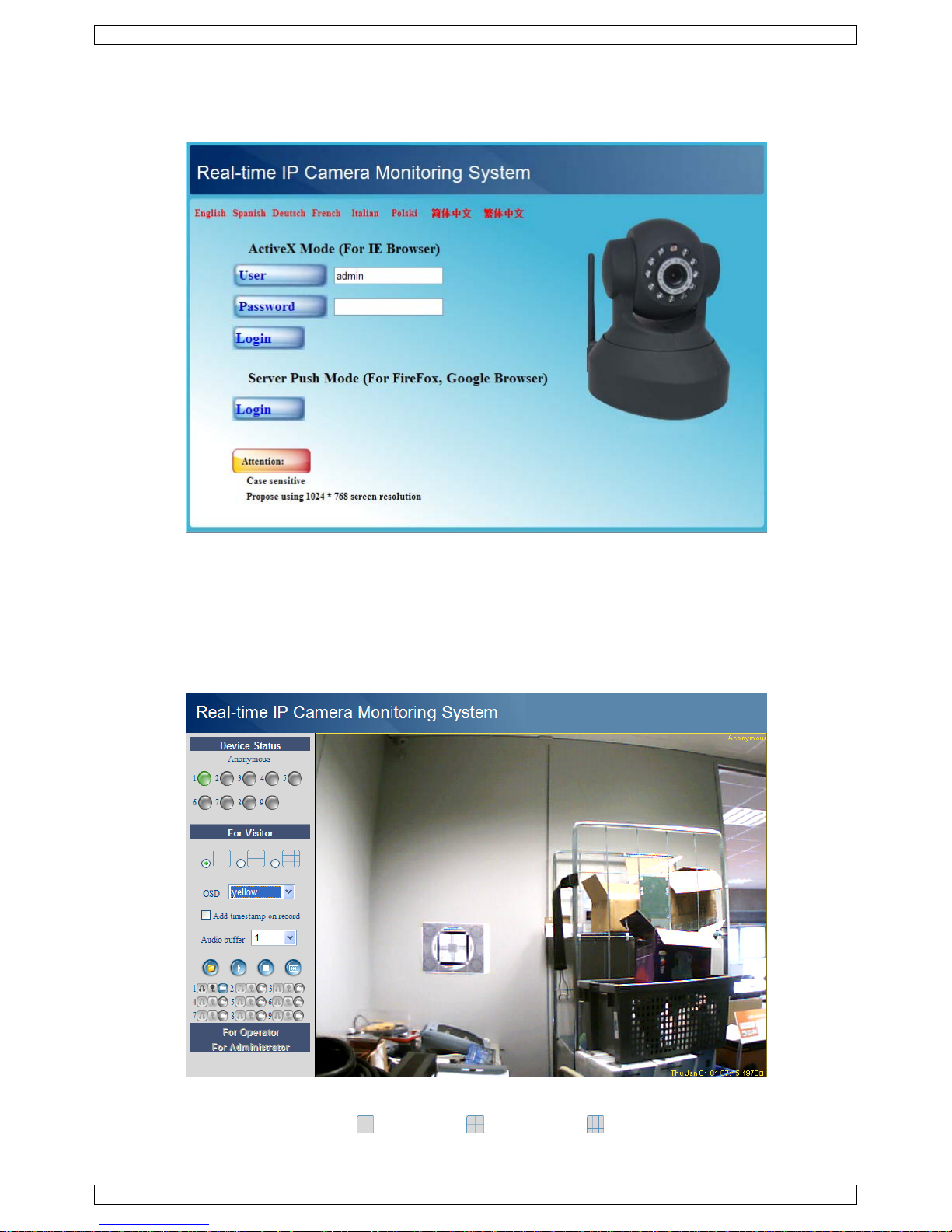
1. When the network setup is completed, double-click the camera to open the camera window. A web browser
with a login page opens:
Note: it is also possible to open a browser window and enter the camera’s IP address in the address bar.
2. Enter your account name and password and click Login. Default, the administrator login is admin without
a password.
Note: use the upper Login button when your browser supports ActiveX Browser Plug-ins. When using a
browser that does not support ActiveX, click on the lower Login button. Some features e.g. full screen,
audio, multi-channel image… will not be available.
3. When logging on to the system with an administrator password, the For Operator screen opens; logging
on with a regular user account will open the For Visitor layout.
8.3 For Visitor layout
• The interface software supports up to 9 cameras. The device status shows the status of each of these
9 cameras. Green = OK, yellow = camera connection problem, red = alarm condition.
• Select the preferred screen layout: shows 1 camera, shows 4 cameras and shows 9 cameras
simultaneously in the camera display pane.
Page 9

CAMIP5N
V. 02 – 22/05/2012 9 ©Velleman nv
• Set the preferred colour for the On Screen Display (OSD): disabled (no OSD), black, yellow, red, white or
blue. The OSD shows the name of the camera in the top right corner of the camera display and a date and
time stamp at the bottom.
• When the Add timestamp on record checkbox is checked, date and time are shown on the recorded file.
Note: set the time via the For Administrator screen (see further).
• Set the audio buffer. The speaker output will be delayed for the indicated number of seconds.
• When the icon is shown the alarm record path (see User Settings below) is opened once an alarm-
triggered recording is finished. Click the icon to switch this function off. The icon changes into .
• Press the snapshot button to take a snapshot of the camera display. In multiple screen layouts, select
the desired camera display first by left-clicking on it. A new window with the picture is opened. Press the
Save button and select the desired location to save the picture.
• Press the view button to start viewing the camera images, press the stop button to stop viewing.
• At the bottom of the left pane, each of the 9 possible cameras has 3 icons. Unavailable cameras are
dimmed.
= audio – talk – record
o Click the icon to enable the camera’s microphone
o Click the icon to enable the camera’s speaker/audio port; a PC microphone (not incl.) is required.
o Click the icon to start recording the selected camera’s images.
Notes:
• When an icon is clicked, it changes to the stop icon . Click this icon to stop the underlying function.
• The recorded file name is cameraname_timestamp.avi
For example: Counter_20081211134442.avi
• The path where the movies will be stored can be set by the administrator in the For Administrator screen
(see further).
8.4 For Operator layout
• When entering an administrator password, the user can open the For Operator layout.
• In this layout, it is possible to pan/tilt the camera using the control panel:
Press on the arrows around the blue button to move in that direction.
Press and hold to move faster.
Press in the centre to start auto-scanning the whole area.
auto tilt (vertical movement)
stop auto tilt
auto pan (horizontal movement)
stop auto pan
switch IR LEDs on
switch IR LEDs off
Page 10

CAMIP5N
V. 02 – 22/05/2012 10 ©Velleman nv
Note: when the camera is in auto tilt/auto pan mode, motion detection and external alarm input are disabled!
• Check the Flip checkbox in case the image is shown upside down.
• Check the Mirror checkbox to mirror the image.
• Set the resolution to 320*240 or 640*480.
• Set the mode to 50Hz or 60Hz.
• Set the brightness and contrast of the image with the “+” and “-” buttons.
Note: the camera is not suitable for outdoor use! The outdoor setting could be used in case the camera is
pointed towards a bright natural light source.
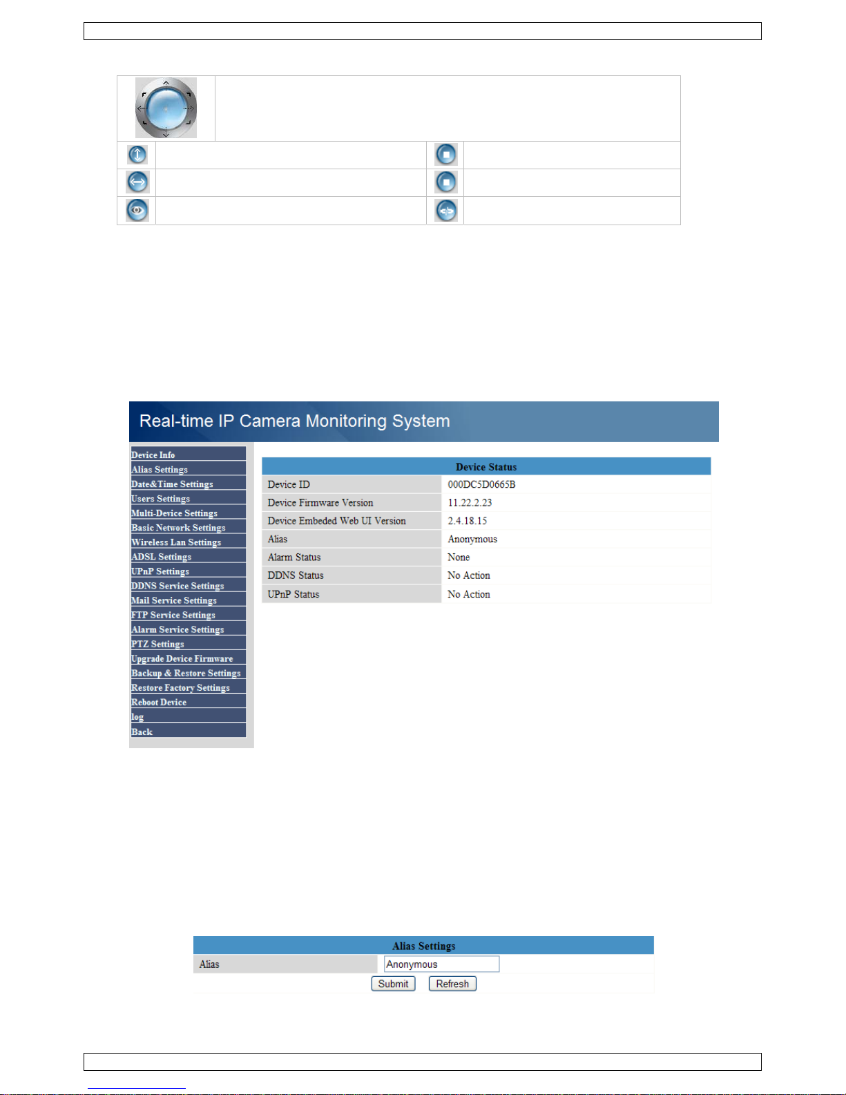
8.5 For Administrator layout
The For Administrator layout is only available when logged in with an administrator account. It is used for
advanced configuration of the cameras.
Notes:
• Select the desired camera before opening the For Administrator layout.
• Depending on the ticked checkboxes, different data entry fields are shown. Hence the display you see for a
certain option might differ from the images used below.
Device info
Device ID, firmware version and Web User Interface version are shown (see image above).
Alias Settings
Set the name of the selected camera.
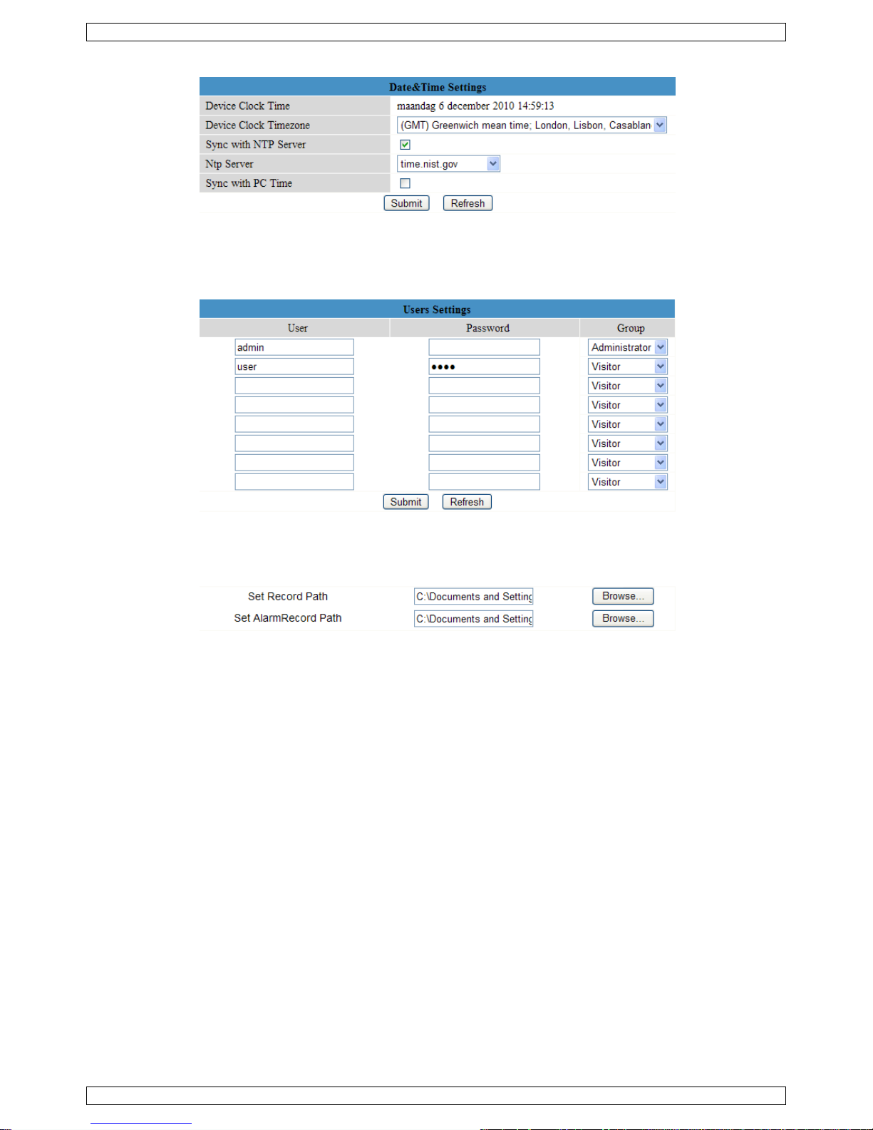
Date&Time Settings
Set date and time data for the camera.
Note: if the timestamp on the display shows the wrong time, try checking the Sync with PC Time checkbox
and press Submit.
Page 11
CAMIP5N
V. 02 – 22/05/2012 11 ©Velleman nv
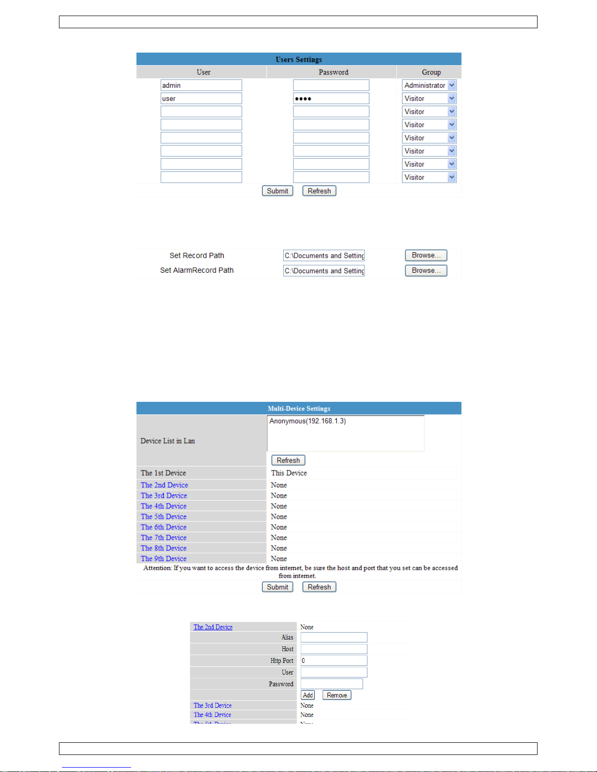
Users Settings
• Up to 8 users can be configured. Enter a user name, a password and select a group (Visitor, Operator or
Administrator). This is also the location to change the administrator’s login name and set a password for the
administrator.
• Set the record and alarm record paths using the Browse buttons. Default for both is c:\\Documents and
Settings\All Users\Documents
Notes when using Windows Vista:
o Remember to add the IP address of the camera to the ‘Trusted sites’.
o The system does not allow to set the Windows System Root Directory as record or alarm record path.
Multi-Device Settings
• Use this menu to manually add extra cameras (up to 9).
• Select a device by clicking on it and enter an alias, host address, Http port, user name and password:
Page 12

CAMIP5N
V. 02 – 22/05/2012 12 ©Velleman nv
• Press Submit to add the device.
Basic Network Settings
• When connected to a DHCP router, check the Obtain IP from DHCP server checkbox, otherwise uncheck
it and fill in the data manually.
• The Network Lamp or network LED [11] indicates the network status of the camera. To disable this LED,
uncheck the Network Lamp checkbox.
Wireless LAN Settings
• Press the Scan button to retrieve a list of available wireless LANs.
• Click on a found network and enter the password if required.
• When you want to use a wireless LAN, check the checkbox and enter SSID, Channel and encryption
method. Depending on the selected encryption method, more data will have to be provided.
Notes:
o Some routers will automatically fill out the necessary data into the fields.
o When entering data manually, check the wireless network settings of your router to find more
information on SSID, Channel, encryption and authentication.
ADSL Settings
When connected to the Internet directly via ADSL, check the checkbox and enter the ADSL User name and
ADSL password you obtained from your Internet Service Provider (ISP).
Page 13
CAMIP5N
V. 02 – 22/05/2012 13 ©Velleman nv
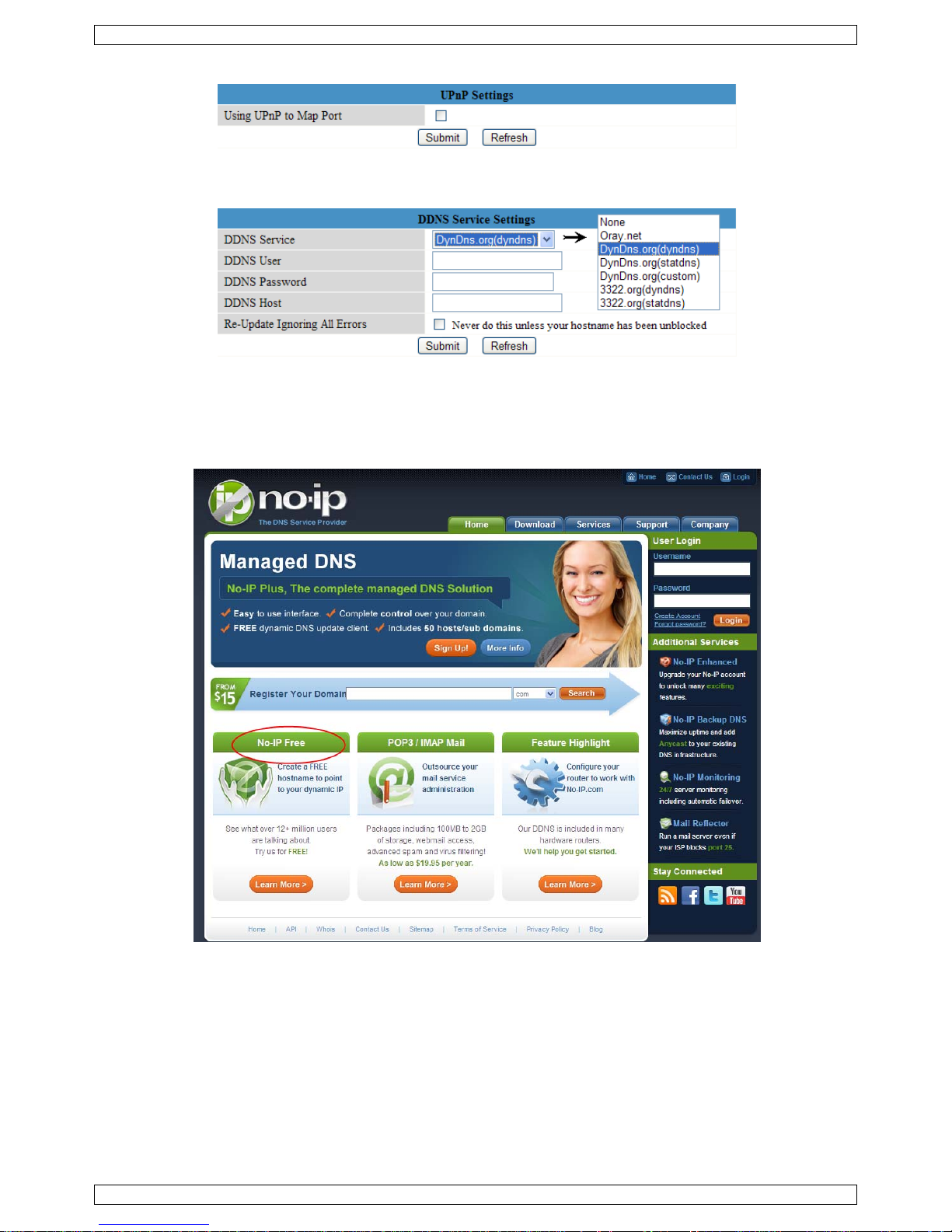
UPnP Settings
Check the checkbox to use the Universal Plug and Play (UPnP) protocol.
DDNS Service Settings
Obtain a domain name from a supported DDNS provider (for example using No-IP, see below) and enter the
data in the appropriate fields.
Using NO-IP as DDNS server
1. Go to the website www.no-ip.com.
2. Click No-IP Free to register.
3. Follow the instructions on www.no-ip.com to create an account.
After registration, you will receive an e-mail from the website.
4. Click the link in the registration e-mail to activate your account.
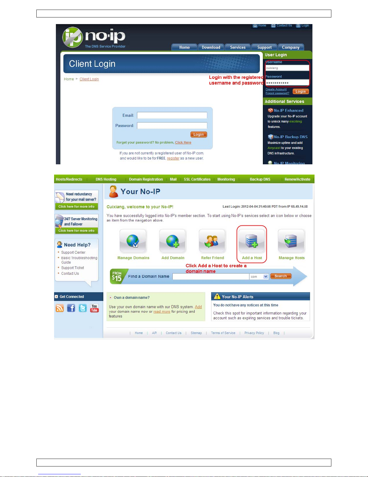
5. Log in on the www.no-ip.com website with the registered user name and password.
Page 14
CAMIP5N
V. 02 – 22/05/2012 14 ©Velleman nv
6. Click Add a Host.
7. Follow the instructions on www.no-ip.com to create a domain name.
When finished, you have to configure the domain name in the camera with the host name, user name and
password from www.no-ip.com. For example: hostname “velleman.no-ip.info”, user name “ipcam”,
password “ipcam2012”.
Proceed as described below.
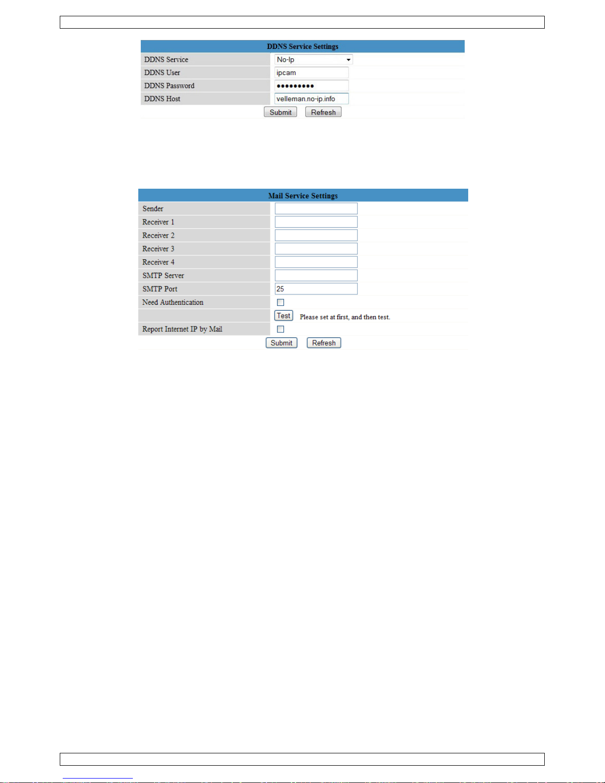
8. Open DDNS Service Settings on the camera’s administrator panel.
9. Select No-Ip as a server.
10. Fill in “ipcam” as DDNS user, fill in “ipcam2012” as DDNS password, and fill in “velleman.no-ip.info” as
DDNS domain and server URL. Click Save to confirm.
The camera will restart.
Page 15
CAMIP5N
V. 02 – 22/05/2012 15 ©Velleman nv
11. When the camera has restarted, open Device Info on the administrator panel, and check if the DDNS
status is successful.
Note: If not, double-check if you have entered the correct host name, user name, and password. Correct if
necessary.
Mail Service Settings
Note: these settings only take effect when the option Send Mail on Alarm is checked in the Alarm Service
Settings menu (see below).
• Fill in a senders e-mail address in the Sender field. This is the mailbox from which the mails will be sent.
• Fill in up to 4 receivers mail addresses. When an alarm condition occurs, mail is sent out to these
addresses.
• Fill out all SMTP data related to the sender’s mailbox. When authentication for the mailbox is required,
check the checkbox and enter user name and password in the appropriate fields.
• When the Report Internet IP by Mail box is checked, a mail is sent whenever a camera comes online
(e.g. after reboot) or a change in IP address occurred. Make sure the port is correctly mapped to the router.
• Press Submit to store the data before performing a ‘mail test’. Following error messages may pop-up:
o Cannot connect to the server
Check network cabling and settings.
o Network error. Please try later.
Check network cabling and settings.
o Server error.
Check the server.
o Incorrect user or password.
Make sure to enter the right user name and password.
o The sender is denied by the server.
Check whether the user needs authentication.
o The receiver is denied by the server.
Could be due to anti-spam settings of the server.
o The message is denied by the server.
Could be due to anti-spam settings of the server.
o The server does not support the authentication mode used by the device.
Try without authentication or use a different server (sender address).
Page 16
CAMIP5N
V. 02 – 22/05/2012 16 ©Velleman nv
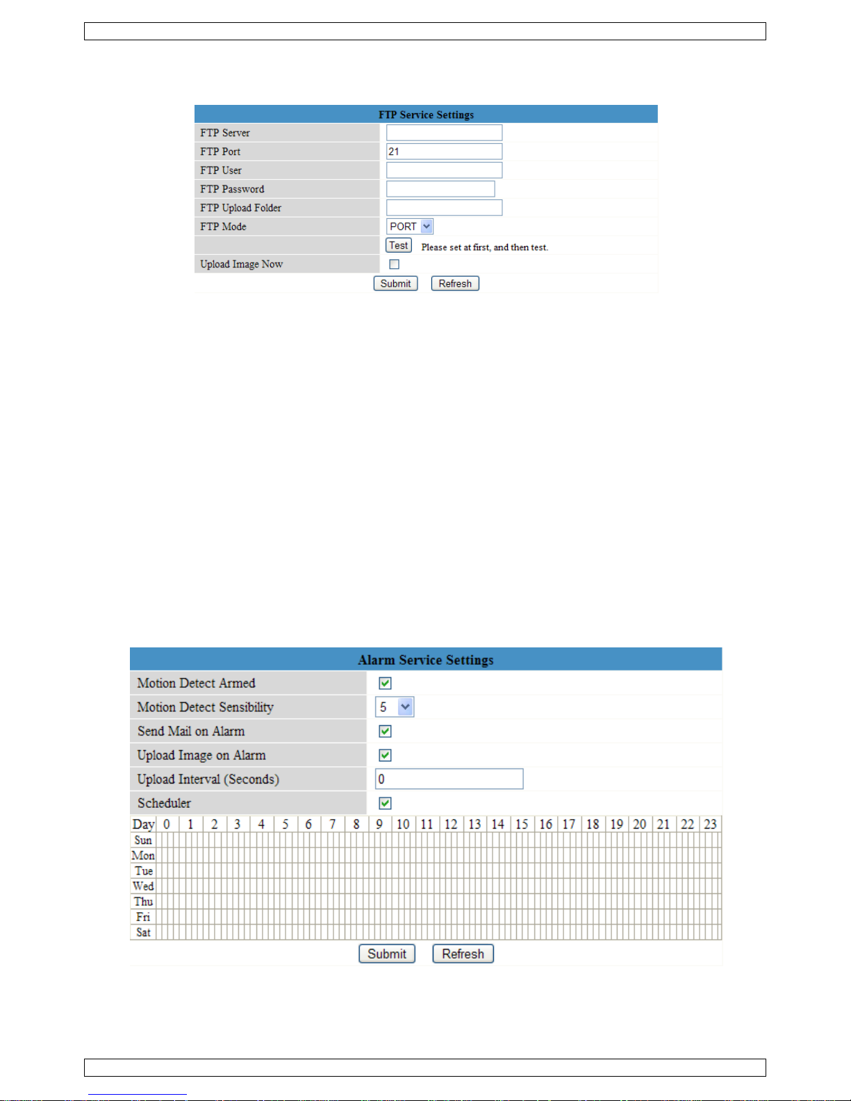
FTP Service Settings
Note: these settings only take effect when the option Upload Image on Alarm is checked in the Alarm
Service Settings menu (see below).
• Fill out all FTP server data. The port is usually set to 21.
• Set the FTP mode to standard (PORT) or passive (PASV).
• When desired, check the Upload Image Now checkbox and set an upload interval (in seconds).
• Press Submit to store the data before performing an ‘FTP test’. A successful test will display FTP test
succeeded. Possible error messages are:
o Cannot connect to server.
Check FTP server address
o Network error. Please try later.
Check network cabling and settings.
o Server error.
Check the FTP server
o Incorrect user or password.
Make sure to enter the right user name and password.
o Cannot access the folder.
Make sure the folder exists and your FTP account is authorized.
o Error in PASV mode.
Make sure the server supports PASV mode.
o Error in PORT mode.
If the device is behind a NAT (Network Address Translation) device, PASV mode must be selected.
o Cannot upload file.
Make sure your FTP account is authorized.
Alarm Service Settings
• Check the Motion Detect Armed checkbox to enable motion detection. This also allows mails to be sent
out (see Mail Service Settings) and image upload to an FTP server (see FTP Service Settings).
Note: when the camera is in auto tilt/auto pan mode (see For Operator layout), motion detection and
external alarm input are disabled!
• The motion detect sensibility can be set between 1 and 10, with 10 being most sensitive.
Page 17

CAMIP5N
V. 02 – 22/05/2012 17 ©Velleman nv
• Check the Send Mail on alarm checkbox to send a mail when an alarm is detected. Make sure to fill out all
fields on the Mail Service Settings page (see above).
• Check the Upload Image on alarm checkbox to upload images to an FTP server when an alarm is
detected. Make sure to fill out all fields on the FTP Service Settings page (see above). When this option is
checked, you can also set the upload interval (in seconds).
• Check the Scheduler checkbox to open the day schedule. Click on the schedule to set the time during
which alarm service must be enabled. Horizontal axis = hours, divided per 15 minutes and vertical axis =
day of the week.
PTZ settings
Set PTZ speeds for the different directions.
Upgrade Device Firmware
Only use this option when problems with the current version are noticed. Do not upgrade if the camera works
fine.
Caution: when the upgrade process is interrupted or a wrong version is installed the camera might not work
anymore.
When clicking on Upgrade Device Fir mware or Embedded Web UI (User Interface), a browser window is
opened. Locate and select the new firmware/web UI.
Backup & Restore settings
Use this option to create a backup or restore your system configuration.
To create a backup, click Submit and choose a location to store the backup file.
To restore a previously made backup, click Browse to locate the backup and click Submit to start restoring.
Restore Factory Settings
Selecting OK will clear the memory and reset the device to factory settings. All settings, e.g. user settings, mail
and FTP settings, alarm schedule… are lost.
Reboot Device
Select OK to reboot the camera.
Note: this will reset the system time. Refer to Date&Time settings.
Page 18
CAMIP5N
V. 02 – 22/05/2012 18 ©Velleman nv
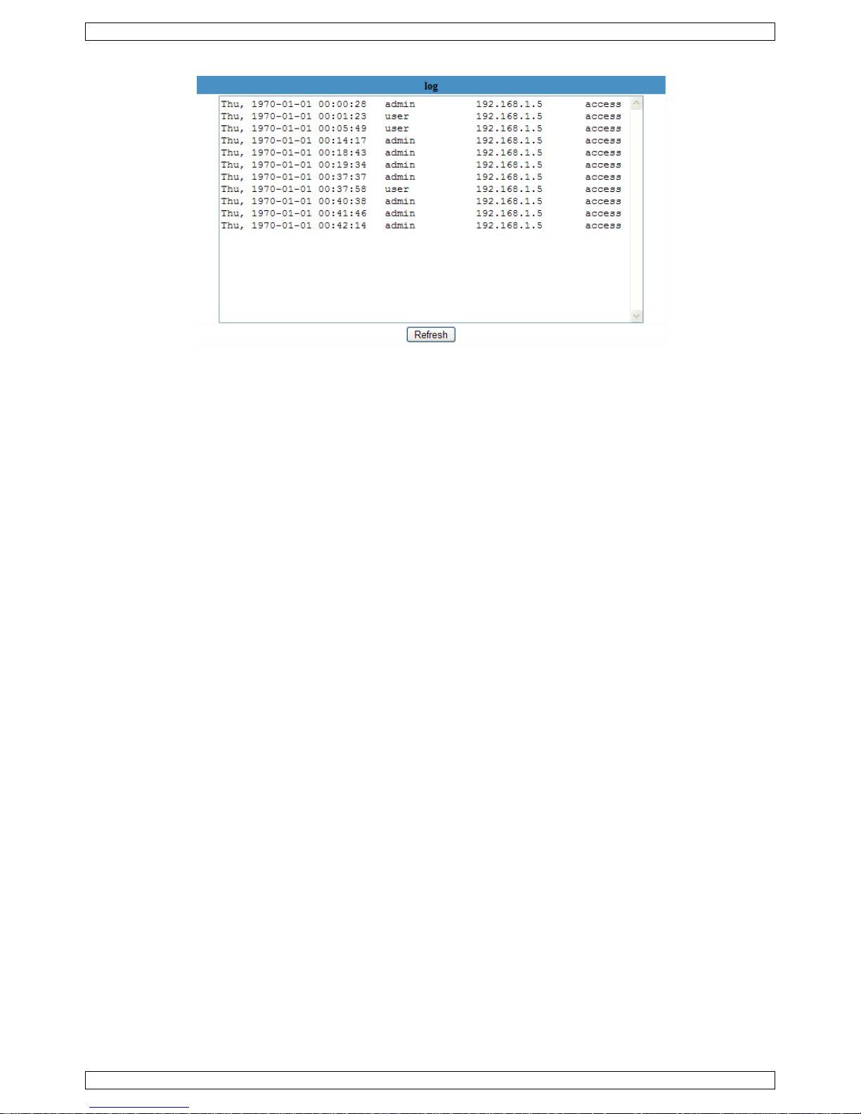
Log
The log shows an overview of everyone who accessed the IP camera. It is cleared when rebooting the system.
Back
Use this option to return to the For Visitor or For Operator page layout.
9. Additional user information
9.1 Password
Default, the administrator login is admin without a password. To enhance security, a new administrator
password should be set as soon as possible (see §8.5 under For Administrator layout – Users Settings).
If the login or password of the administrator(s) are forgotten or corrupt, the system can be reset to factory
defaults (admin, no password) by pressing and holding the RESET button at the bottom of the camera for
about 5 seconds.
9.2 WiFi
1. Refer to the user manual of your wireless router to obtain network information e.g. SSID, Channel,
Security, authentication, encryption…
2. Use previously obtained information to configure your CAMIP5N via a fixed network cable (For
Administrator – Wireless LAN settings).
3. Reboot the CAMIP5N.
4. Wait at least 30 seconds before unplugging the network cable. Then unplug the power supply.
5. Re-insert the power plug.
After about 30 seconds, the camera should be up and running in WiFi mode.
9.3 Connect the camera on an ADSL network
1. Connect the camera to a PC. The easiest way is to use a router. If nPo router is available, you must use a
cross cable (not incl.) to connect the CAMIP5N directly to the PC’s 8P8C (RJ45) port and set the IP
addresses on PC and camera manually.
2. Configure the camera with the IP camera tool (see §8.1).
3. Log on to the camera as administrator and configure ADSL settings (user name + password).
4. Configure the DDNS Service Settings and click Submit. The camera reboots.
5. Connect the camera directly to the ADSL modem. It is now available through the internet by entering the
domain name in your internet browser.
Note: set the option Report ADSL IP by mail under Mail Service Settings to receive the camera’s IP
address by mail.
9.4 Connect the camera via a router
1. Connect the camera to the LAN and configure the camera with the IP camera tool (see §8.1).
2. Log on to the camera as administrator and configure DDNS Service Settings.
3. Click Submit to reboot the camera.
The camera is now available through the internet by entering the domain name in your internet browser.
Page 19

CAMIP5N
V. 02 – 22/05/2012 19 ©Velleman nv
9.5 Static IP users
When using only fixed IP addresses, a DDNS service is not required. There are two ways to find out the static
WAN IP address of the camera:
• Connect a computer to the same connection as the camera and open a website that tells you what IP
address you are on (e.g. www.whatismyip.com
).
• Log on to the router and view the status page to find out its WAN IP address. To connect to the IP camera,
enter the WAN IP address of the router followed by the port number to which the camera is connected into
the address bar of a browser (e.g. http://116.25.51.115:85/). Make sure UPnP is enabled or the camera is
added to the router’s virtual mapping list.
9.6 Using DDNS
DDNS stand for Dynamic Domain Name Server. It is a service that links dynamic IP addresses to fixed domain
names. This way, the camera will always be accessible by using a domain name, no matter which IP address
was assigned to it.
1. To obtain a domain name and password, refer to a DDNS website on the internet.
2. Enter the name and password in the DDNS Service Settings page and press Submit. The camera
reboots.
3. Check the UPnP settings. If the status is not Succeed, try to change the port number in the Basic
Network Settings page. Submit and reboot the camera.
4. To connect to the camera, enter domain name of the camera in the address bar of a web browser. The
prefix www. is not required. When multiple cameras are connected to the router, add the port number
behind the domain name (e.g. http://ipcam. Video.net:85/)
9.7 Using a mobile phone
It is possible to connect a smartphone to the IP camera. Many third-party software developers offer compatible
software. An example is the “IP Cam Viewer” software which is available from the iTunes and Google Play
stores. After installation, just enter the external hostname, IP port, username and password, and you can view
the images on your smartphone.
10. Troubleshooting
IP address
Always make sure the camera is on the same subnet (same subnet mask) as the PC you are using to
configure it
Network configuration
• Check if your HTTP server software is configured and running properly.
• If the camera is behind a firewall, make sure the firewall software is allowing inbound connections on
port 80. If not, use an alternate port. The same goes for certain anti-spam and anti-virus software
packages.
• If the camera is behind a cable/DSL router, make sure to configure port forwarding properly. Refer to the
user manual of the router.
No image
• Video streaming is transmitted by the ActiveX controller. If this controller is not installed properly, no video
image is shown.
• When you install the IP Camera Tool, the ActiveX controller is installed at the same time. If not, download
the ActiveX controller from the internet and set the safety properties of your web browser so it accepts
ActiveX content.
Slow image
The frame rate of the shown video depends on a number of external factors, e.g.:
• Network bandwidth
• PC performance and display settings
• Number of visitors that are viewing the camera simultaneously
• Network equipment (e.g. use a switch in stead of a hub for multiple IP cameras).
Camera not available via Internet
Possible reasons may include:
• ActiveX controller is not installed/working properly.
Note: a standard Firefox browser does not support ActiveX. However there are plug-ins available on the
Internet.
Page 20

CAMIP5N
V. 02 – 22/05/2012 20 ©Velleman nv
• The port of the IP camera is blocked by a firewall or anti-virus software. In this case, try using a different
port number.
• Port mapping failed. Either enable UPnP (via UPnP Settings) or edit the routers Virtual map list (refer to
the user manual of your router).
11. Technical specifications
sensor ¼" colour CMOS sensor
lens 3.6mm / F2.4
minimum illumination 0.5 lux (IR LEDs off)
resolution 640 x 480 pixels (300 000 pixels)
built-in pan/tilt
controllable through internet
left/right 300°
up/down 120°
supported network protocols
TCP/IP, UDP, IMCP, SMTP, HTTP, FTP, DNS, DDNS, DHCP,
PPPoE, GPRS
wired connection Ethernet 10/100 Base-T and 8P8C (RJ45)
wireless connection
standard IEEE 802.11b/g/n
supports WEP, WPA & WPA2 encryption
network connection
supports 3 methods fixed IP, DHCP, PPPoE
supports DHCP, installs the IP address automatically (plugand-play network)
audio built-in microphone
video
compression format MJPEG
frame rate 15 FPS (VGA), 30 FPS (QVGA)
resolution 640 x 480 (VGA), 320 x 240 (QVGA)
dimensions 110 x 100 x 108mm
weight ±333g
Use this device with original accessories only. Velleman nv cannot be held responsible in the event
of damage or injury resulted from (incorrect) use of this device.
For more info concerning this product and the latest version of this manual, please visit our website
www.velleman.eu.
The information in this manual is subject to change without prior notice.
Page 21
V.
1
.
A
aBeDa
be
2
.
3
.
Ra
•
•
•
•
•
4
.
•
•
•
•
•
•
02 – 22/05/2
Inlei
n alle ing
e
langrijke
m
Dit s
y
weg
g
batt
e
tere
c
bren
g
Heb
t
nk u voor u
w
schadigd tij
d
Veili
g
Ho
u
El
e
om
ge
s
De
mtoe
Alge
m
adpleeg de
V
Leer eerst
Om veilig
h
aangebrac
Gebruik h
e
De garanti
dealer zal
houden.
Installeer
e
Eige
n
eenvoudig
pan- en til
t
beveiligde
nachtzicht
ingebouw
d
alarmberi
c
012
ding
zetenen v
a
ilieu-info
r
mbool op
h
eworpen, d
rijen) niet
b
htkomen v
o
en. Respe
c
u vragen,
aankoop!
ens het tra
heidsi
n
d buiten h
e
ktrocutieg
e
dodelijke e
l
choold pers
onteer of
o
stel. Voor o
n
ene ri
c
elleman
®
Gebruik
vloeistof
f
Bescher
m
Bescher
m
de functies
eidsredene
n
ht valt niet
o
t toestel en
e geldt niet
de verantw
o
n gebruik
d
schapp
te installer
e
beweging
o
Wi-Fi-aansl
u
dankzij 11
i
e microfoo
n
ht bewegin
g
GEB
R
n de Euro
p
matie bet
r
et toestel o
f
it toestel sc
h
ij het gewo
n
or recyclag
e
teer de pla
a
contactee
r
Lees deze
h
nsport, inst
a
structie
t bereik va
n
vaar bij h
e
ektroshock
s
oneel.
pen dit toe
s
derhoud o
f
htlijne
n
service- e
het toestel
e
en.
tegen sto
f
tegen sch
o
van het toe
s
mag u gee
nder de ga
kel waarvo
o
voor schad
e
ordelijkhei
d
eze camera
en
n
p afstand
iting en be
k
nfraroodled
s
en luidspr
e
swaarnemi
n
UIKE
R
ese Unie
effende di
t
de verpak
k
ade kan to
e
e huishoud
. U moet di
tselijke mili
e
dan de pl
a
andleiding
g
lleer het da
s
kinderen e
t openen v
a
te vermijd
e
tel NOOIT.
reserveond
n kwaliteit
nkel binn
e
en extrem
e
kken. Ver
m
tel kennen
n wijziginge
rantie.
r het gema
a
door het n
e
afwijzen v
o
niet voor ill
abelde LA
N
ker
g via e-ma
i
CAMIP5N
21
SHA
N
product
ing geeft a
a
brengen a
a
elijke afval;
t toestel na
a
uwetgevin
g
atselijke
a
rondig voo
r
n niet en ra
a
n onbevoeg
d
n het toest
e
n. Open de
Er zijn gee
n
erdelen, co
n
sgarantie
a
nshuis. Be
temperatu
r
ijd brute k
r
voor u het
g
n aanbreng
e
kt is. Bij on
geren van
b
or defecten
egale prakti
-aansluitin
g
l of upload
v
DLEI
D
n dat, als h
n het milie
u
het moet bi
r uw verdel
.
utoriteite
n
u het toest
e
dpleeg uw
en.
l. Raak ge
e
behuizing
n
door de g
e
tacteer uw
d
chteraan d
e
scherm teg
e
en.
acht tijdens
aat gebruik
n. Schade
d
oordeelkun
d
epaalde ric
of problem
e
jken en res
p
an beelden
ING
et na zijn le
v
. Gooi dit t
o
j een gespe
c
er of naar e
e
betreffen
d
l in gebrui
k
dealer.
n kabels aa
n
iet zelf en l
a
bruiker ver
v
ealer.
ze handleid
n regen, vo
de bedieni
n
en.
oor wijzigi
n
ig gebruik
v
htlijnen in d
n die hier r
e
ecteer iede
r
naar FTP.
enscyclus
w
estel (en e
v
ialiseerd b
e
n lokaal re
c
de verwi
j
neemt. W
e
die onder
s
at reparati
e
angbare o
n
ing.
chtigheid e
n
g.
gen die de
g
ervalt de g
a
eze handlei
d
chtstreeks
rs privacy.
©Vellema
n
ordt
entuele
drijf
yclagepunt
dering.
rd het toest
troom staa
s over aan
derdelen in
opspatten
d
ebruiker h
e
rantie.
ing en uw
verband m
e
nv
el
n
dit
e
eft
e
Page 22

CAMIP5N
V. 02 – 22/05/2012 22 ©Velleman nv
5. Omschrijving
Raadpleeg de afbeeldingen op pagina 2 van deze handleiding.
1 lichtsensor 7 audio-uitgang
2 infraroodleds (11x) 8 audio-ingang
3 luidspreker 9 8P8C (RJ45)-aansluiting
4 lens 10 voedingsled
5 microfoon 11 netwerkled
6 Wi-Fi-antenne 12 5 VDC ingangsaansluiting (2 A)
6. De hardware installeren en gebruiken
1. Kies een geschikte montageplaats voor de camera en houd rekening met volgende punten:
o monteer de camera nooit op een plaats onderhevig aan extreme temperaturen en trillingen;
o monteer de camera nooit in de buurt van elektromagnetische velden;
o richt de camera nooit naar de zon of naar andere weerkaatsende objecten toe.
2. De camera is geschikt voor alleenstaand gebruik of voor muur-/plafondmontage dankzij de meegeleverde
beugel en de twee schroeven. Bevestig de camera aan de montagebeugel met de centrale schroef. Richt de
camera.
3. Steek de antenne [6] in de aansluiting en/of steek de meegeleverde netwerkkabel in de 8P8C (RJ45)-
aansluiting [9].
Opmerking: U kunt de camera rechtstreeks op de 8P8C (RJ45)-aansluiting van de computer aansluiten.
Gebruik hiervoor een gekruiste kabel (niet meegeleverd). De camera moet daarna handmatig ingesteld
worden.
4. Sluit indien gewenst een externe microfoon (niet meegeleverd) aan op de audio-ingang [8].
5. Sluit indien gewenst een externe luidspreker aan op de audio-uitgang [7].
6. Steek de voedingsstekker van de voedingsadapter in de 5VDC-ingang [12]. Gebruik enkel de
meegeleverde adapter of een adapter met dezelfde eigenschappen.
7. Steek de voedingsadapter in het stopcontact (100 ~ 240 VAC/50 ~ 60 Hz).
Opmerkingen:
• De initialisatie van de camera duurt een 30-tal seconden.
• Tijdens de initialisatie beweegt de camera om de pan- en tiltbewegingen te testen.
• Regel de lens [4] bij indien u een onscherp beeld krijgt.
7. De software installeren
Steek de meegeleverde cd-rom in de cd-romdrive van uw computer.
Systeemvereisten: CPU ≥ 2,06 GHz / geheugen ≥ 256 MB / netwerk ≥ 10 MB / grafische kaart ≥ 64 MB /
aanbevolen besturingssysteem: Windows 2000 of XP / Mac.
Windows
1. Dubbelklik op IPCamSetup.exe om de software te installeren.
Page 23

CAMIP5N
V. 02 – 22/05/2012 23 ©Velleman nv
2. Volg de instructies op het scherm. Klik op Next om de installatie te starten.
3. Klik opnieuw op Next.
4. Herstart de computer om de installatie te voltooien. Vink Yes I want to restart my computer now aan
en klik op Close.
Na de herstart verschijnt IP Camera Tool op het bureaublad.
Mac
1. Open de folder “For MAC”.
2. Open de folder “IP camera Tool “ en kopieer de tool naar uw Mac.
8. De software configureren
Zorg ervoor dat alle verbindingen goed aangesloten zijn (zie ook §6) en dubbelklik op IP Camera Tool om de
software te starten.
8.1 IP Camera Tool
1. De software zoekt automatisch naar de beschikbare camera’s op het LAN-netwerk. Er zijn 3 mogelijkheden:
o Er zijn geen camera’s beschikbaar. Controleer de bekabeling en zorg dat de camera is ingeschakeld
indien de software na 1 minuut geen enkele camera heeft gevonden.
o Er zijn camera’s beschikbaar en ze staan opgelijst (zie afbeelding hieronder).
Page 24
CAMIP5N
V. 02 – 22/05/2012 24 ©Velleman nv
o Er zijn camera’s beschikbaar maar ze staan niet op hetzelfde subnet als deze van uw computer. Het
bericht Subnet doesn’t match, dbclick to change verschijnt. Wijzig de configuratie van het subnet
via het configuratiemenu van het netwerk (zie verder).
Opmerking: Zorg dat het DHCP in de router ingeschakeld is en de MAC-adresfiltering uitgeschakeld is. Bij
blijvende problemen, schakel alle actieve firewalls of antivirussoftware uit en probeer opnieuw.
Windows:
Mac:
2. Open het optiemenu door met de rechtermuisknop op een camera in de lijst te klikken.
Opmerking: De opties zijn enkel zichtbaar na de volledige initialisatie van de camera.
Basiseigenschappen (Basic properties)
Algemene informatie over de camera:
Page 25

CAMIP5N
V. 02 – 22/05/2012 25 ©Velleman nv
Netwerkconfiguratie (Network Configuration)
Een overzicht van de netwerkinstellingen van de camera:
• Vink Obtain IP from DHCP server aan indien aangesloten op een DHCP-router. Indien niet, vink uit en
geef de data handmatig in.
• Wijzig het IP-adres of het subnetmasker bij een ongeldig subnetadres.
• Neem bij twijfel over de subnetinstellingen contact op met een netwerkbeheerder.
De firmware upgraden (Upgrade firmware)
Het is aanbevolen om de firmware te upgraden enkel en alleen indien u problemen ondervindt met de huidige
versie. U hoeft de de firmware niet te upgraden indien de camera normaal functioneert.
Opgelet: U kunt de camera ernstig beschadigen indien het upgradeproces onderbroken wordt of een verkeerde
versie wordt geïnstalleerd.
Geef de login en het wachtwoord van de beheerder in.
Opmerking: De standaard login is admin zonder wachtwoord.
De cameralijst verversen (Refresh Camera List)
Ververs de lijst wanneer u een nieuwe camera aan het netwerk toevoegt.
ARP-buffer wissen (Flush ARP Buffer)
Bij zowel een draad- als een draadloze aansluiting kunnen zich problemen voordoen met het ARP (Address
Resolution Protocol) en kan de camera via de browser niet beschikbaar zijn. Wis in dit geval de ARP-buffer.
Over de camera (About IP Camera Tool)
Bijkomende informatie over de camera.
Page 26
CAMIP5N
V. 02 – 22/05/2012 26 ©Velleman nv
8.2 Login van de camera
1. Dubbelklik na de volledige configuratie van het netwerk op de camera. Er verschijnt een webbrowser met
aanmeldpagina:
Opmerking: U kunt het IP-adres van de camera ook in de adresbalk van een webbrowser ingeven.
2. Geef uw accountnaam en wachtwoord in en klik daarna op Login. De standaard login is admin zonder
wachtwoord.
Opmerking: Gebruik de aanmeldknop bovenaan indien uw browser ActiveX gebruikt. Gebruikt u een
browser dat ActiveX niet ondersteunt, klik dan op de onderste aanmeldknop. Merk op dat sommige
functies zoals een volledige schermweergave en een audio dan niet beschikbaar zijn.
3. Bij het inloggen met een administratorpaswoord verschijnt het venster For Operator. Bij het inloggen met
een gebruikerspaswoord verschijnt het venster For Visitor.
8.3 For Visitor (bezoeker)
• De software ondersteunt tot 9 camera’s. Onder Device Status ziet u de status van elke aangesloten
camera: groen = oké, geel = aansluitingprobleem, rood = alarm.
• Kies de gewenste schermlay-out: = 1 camera, = 4 camera’s, = 9 camera’s.
Page 27

CAMIP5N
V. 02 – 22/05/2012 27 ©Velleman nv
• Kies de gewenste kleur voor het OSD-menu: disabled (geen OSD), zwart, geel, rood, wit of blauw. De OSD
geeft de cameranaam rechtsboven het scherm weer; datum en tijd verschijnen onderaan.
• Vink Add timestamp on record aan om datum en tijd op de opname weer te geven.
Opmerking: Stel de tijd in via het For Administrator-menu (zie verder).
• Stel de audiobuffer in. De luidspreker wordt gedurende het aantal ingestelde seconden uitgeschakeld.
• Bij het verschijnen van de icoon worden alarm- en opnamepad (zie Gebruikersinstellingen
hieronder) geopend van zodra de opname wordt beëindigd. Klik op de icoon om deze functie uit te
schakelen. De icoon wijzigt in .
• Druk op voor een screenshot. Selecteer eerst de gewenste camera door met de linkermuisknop op de
beeldweergave te klikken. Er verschijnt een nieuw scherm met daarin de screenshot. Druk op Save en
selecteer de doelmap om de screenshot te bewaren.
• Druk op om de beeldweergave van een camera in te schakelen of op om de beeldweergave uit te
schakelen.
• Onderaan het linkerpaneel vindt u voor de 9 camera’s telkens 3 iconen:
= audio – spraak – opname. Niet-beschikbare camera’s zijn wazig gemaakt.
o Schakel de microfoon van de camera in met .
o Schakel de luidspreker van de camera in met . Voor deze functie moet u een microfoon (niet
meegeleverd) op uw computer aansluiten.
o Druk op om de opnamefunctie voor die camera in te schakelen.
Opmerkingen:
• Bij het aanklikken van een icoon verandert de icoon . Druk op deze icoon om zijn functie uit te
schakelen.
• De bestandsnaam van de opname wordt cameranaam_tijdsaanduiding.avi.
Bijvoorbeeld: ingang_20081211134442.avi.
• Het pad waaronder de opnames bewaard worden, zijn door de beheerder onder For Administrator
instelbaar (zie verder).
8.4 For Operator (gebruiker)
• Bij het inloggen met wachtwoord verkrijgt u toegang tot het gebruikersmenu For Operator.
Page 28
CAMIP5N
V. 02 – 22/05/2012 28 ©Velleman nv
• Hier kunt u de camera ook bedienen:
Verplaats de camera met de pijltjes.
Houd ingedrukt om de camera sneller te verplaatsen.
Druk op de blauwe knop in het midden om de zone automatisch af te
scannen.
auto tilt (verticale beweging)
stop auto tilt
auto pan (horizontale beweging)
stop auto pan
IR-leds inschakelen
IR-leds uitschakelen
Opmerking: Tijdens het automatisch afscannen, zijn de bewegingswaarneming en de externe alarmingang
uitgeschakeld!
• Vink Flip aan om het beeld om te draaien.
• Vink Mirror aan om het beeld te spiegelen.
• Stel de resolutie in op 320*240 of 640*480.
• Stel de snelheid in op 50 Hz of 60 Hz.
• Stel helderheid en contrast van het beeld in met + en –.
Opmerking: Deze camera is niet geschikt voor gebruik buitenshuis! Gebruik de instellingen voor buitenshuis
indien de camera naar een heldere lichtbron is gericht.
8.5 For Administrator (beheerder)
Het beheerdermenu For Administrator is enkel beschikbaar indien u inlogt met beheerderwachtwoord. Dit
menu beschikt over geavanceerde instelmogelijkheden.
Opmerkingen:
• Kies de gewenste camera alvorens het beheerdermenu te openen.
• Verscheidene invoervelden zijn beschikbaar naargelang de aangevinkte vakjes. De afbeeldingen hieronder
kunnen dus verschillen met de werkelijkheid.
Cameragegevens (Device info)
ID-nummer, versie van de firmware en van de gebruikersinterface (zie afbeelding hierboven).
Aliasinstellingen (Alias Settings)
Geef hier de naam van de camera in.
Page 29
CAMIP5N
V. 02 – 22/05/2012 29 ©Velleman nv
Datum- en tijdsinstellingen (Date&Time Settings)
Stel hier datum en tijd in.
Opmerking: Vink Sync with PC Time aan en druk op Submit bij een verkeerde tijdsaanduiding op de
display.
Gebruikersinstellingen (Users Settings)
• Als beheerder kunt u tot 8 gebruikers beheren. Geef gebruikersnaam en wachtwoord in en selecteer een
groep (Visitor, Operator of Administrator). Hier kunt u ook uw aanmeldnaam en wachtwoord wijzigen.
• Stel het opname- en alarmpad in met Browse. Standaard is dit pad C:\Documents and Settings\All
Users\Documents.
Opmerkingen voor Windows Vista®-gebruikers:
o Geef ook het IP-adres in van vertrouwde websites.
o U kunt de Windows-rootfolder niet als opname- of alarmpad instellen.
Page 30

CAMIP5N
V. 02 – 22/05/2012 30 ©Velleman nv
Instellingen voor meerdere camera’s (Multi-Device Settings)
• Gebruik dit menu om handmatig tot 9 camera’s toe te voegen.
• Selecteer een camera door deze te aan te klikken en een alias, een bezoekersadres, een http-poort, een
gebruikersnaam en een wachtwoord in te geven:
• Druk op Submit om de camera toe te voegen.
Basisinstellingen van het netwerk (Basic Network Settings)
• Vink Obtain IP from DHCP server aan indien aangesloten op een DHCP-router. Indien niet, vink uit en
geef de gegevens handmatig in.
• Network Lamp geeft de status van de camera in het netwerk weer. Vink uit om de led [11] uit te
schakelen.
Page 31

CAMIP5N
V. 02 – 22/05/2012 31 ©Velleman nv
Instellingen draadloos LAN
• Druk op Scan om een lijst weer te geven van alle beschikbare draadloze LAN-netwerken.
• Klik op het beschikbare netwerk en geef indien nodig het wachtwoord in.
• Vink Using Wireless Lan aan en geef een SSID, het kanaal en de encryptie in indien u een draadloos LAN-
netwerk wenst te gebruiken. U zult meer gegevens moeten ingeven afhankelijk van de geselecteerde
encryptie.
Opmerkingen:
o Bepaalde routers geven automatisch de nodige gegevens in.
o Raadpleeg de draadloze netwerkinstellingen van de router voor meer informatie over SSID, kanaal,
encryptie en authenticatie bij een handmatige invoer van de gegevens.
ADSL-instellingen (ADSL Settings)
Vink aan en geef gebruikersnaam en ADSL-wachtwoord in bij aansluiting via ADSL. Deze gegevens zijn
verkrijgbaar bij uw internetprovider.
UPnP-instellingen (UPnP Settings)
Vink aan om het UPnP-protocol (Universal Plug and Play) te gebruiken.
Instellingen DDNS Service (DDNS Service Settings)
Vraag een domeinnaam aan bij uw DDNS-provider (gebruik bijvoorbeeld No-IP, zie onder) en geef de
gegevens in de daartoe bestemde velden in.
Page 32

CAMIP5N
V. 02 – 22/05/2012 32 ©Velleman nv
NO-IP gebruiken als DDNS-server
1. Ga naar de website www.no-ip.com.
2. Klik op No-IP Free om zich te registreren.
3. Volg de instructies op de website www.no-ip.com om een account aan te maken.
Na registratie ontvangt u een e-mail van de website.
4. Klik op de link in de registratiemail om uw account te activeren.
5. Log in op de website www.no-ip.com met de geregistreerde gebruikersnaam en paswoord.
Page 33

CAMIP5N
V. 02 – 22/05/2012 33 ©Velleman nv
6. Klik op Add a Host.
7. Volg de instructies op de website www.no-ip.com om een domeinnaam aan te maken.
Vervolgens, moet u de domeinnaam configureren in de camera met de hostnaam, gebruikersnaam en
paswoord van de website www.no-ip.com. Bijvoorbeeld: hostnaam “velleman.no-ip.info”, gebruikersnaam
“ipcam”, paswoord “ipcam2012”.
Ga als volgt te werk.
8. Open DDNS Service Settings op het administratiepaneel van de camera.
9. Selecteer No-Ip als server.
10. Geef “ipcam” in als DDNS-gebruiker, geef “ipcam2012” in als DDNS-paswoord, en geef “velleman.no-
ip.info” in als DDNS-domein en server URL. Klik op Save om te bevestigen.
De camera wordt herstart.
11. Na het herstarten van de camera, open Device Info op het administratiepaneel, en verifieer of de
DDNS-status succesvol is.
Opmerking: Indien dit niet het geval is, controleer nogmaals of u hostnaam, gebruikersnaam, en
paswoord correct heeft ingevoerd. Corrigeer indien nodig.
Page 34

CAMIP5N
V. 02 – 22/05/2012 34 ©Velleman nv
E-mailinstellingen (Mail Service Settings)
Opmerking: Deze instellingen zijn enkel geldig indien de optie Send Mail on alarm aangevinkt is in het menu
Alarm Service Settings (zie hieronder).
• Geef het adres in van de afzender in het veld Sender. Dit is de mailbox waaruit de e-mails worden
verzonden.
• U kunt tot 4 ontvangadressen ingeven. Bij alarm wordt een e-mail naar elk van de ingegeven adressen
verzonden.
• Geef alle SMTP-gegevens in. Bij authenticatie van de mailbox, vink het vakje aan en geef gebruikersnaam
en wachtwoord in.
• Vink Report Internet IP by Mail aan om een e-mail te krijgen van zodra de camera online beschikbaar is
(bv. na een herstart) of bij wijziging van het IP-adres.
• Druk op Submit om de gegevens te bewaren alvorens het systeem te testen. Volgende foutmeldingen zijn
mogelijk:
o Geen aansluiting met de server.
Controleer de bekabeling en de instellingen van het netwerk.
o Netwerkfout. Probeer het later opnieuw.
Controleer de bekabeling en de instellingen van het netwerk.
o Serverfout.
Controleer de server.
o Gebruikersnaam of wachtwoord niet correct.
Geef uw gebruikersnaam en wachtwoord correct in.
o Afzender geweigerd door de server.
Controleer of de gebruiker authenticatie hoeft.
o Bestemmeling geweigerd door de server.
Controleer de antispaminstellingen van de server.
o Bericht geweigerd door de server.
Controleer de antispaminstellingen van de server.
o De server ondersteunt geen authenticatie.
Probeer zonder authenticatie of gebruik een andere server.
Instellingen FTP Service (FTP Service Settings)
Opmerking: Deze instellingen zijn enkel geldig indien de optie Upload Image on Alarm aangevinkt is in het
menu Alarm Service Settings (zie hieronder).
• Geef alle FTP-gegevens in. De FTP-poort is doorgaans 21.
• Stel FTP Mode in op standaard (PORT) of passief (PASV).
• Indien gewenst, vink Upload Image Now aan en stel een interval in (in seconden).
Page 35

CAMIP5N
V. 02 – 22/05/2012 35 ©Velleman nv
• Druk op Submit om de gegevens te bewaren alvorens het systeem te testen. Bij een geslaagde test
verschijnt er FTP test succeeded. Volgende foutmeldingen zijn mogelijk:
o Geen aansluiting met de server.
Controleer het adres van de FTP-server.
o Netwerkfout. Probeer het later opnieuw.
Controleer de bekabeling en de instellingen van het netwerk.
o Serverfout.
Controleer de FTP-server.
o Gebruikersnaam of wachtwoord niet correct.
Geef uw gebruikersnaam en wachtwoord correct in.
o Toegang tot de map geweigerd.
Zorg ervoor dat de map bestaat en dat uw FTP-account toegang heeft.
o Fout in PASV-modus.
Zorg ervoor de server de PASV-modus ondersteunt.
o Fout in PORT-modus.
Selecteer de PASV-modus indien uw router zich achter een NAT (Network Address Translation) apparaat
bevindt.
o Upload van het bestand geweigerd.
Zorg ervoor dat uw FTP-account toegang heeft.
Alarminstellingen (Alarm Service Settings)
• Vink Motion Detect Armed aan om de bewegingswaarnemingfunctie in te schakelen. Hierdoor zult u ook
e-mails ontvangen (zie: E-mailinstellingen) en beelden naar een FTP-server kunnen uploaden (zie:
Instellingen FTP Service).
Opmerking: Tijdens het automatisch afscannen (zie: For Operator), zijn de bewegingswaarneming en de
externe alarmingang uitgeschakeld!
• Stel de gevoeligheid van de sensor in tussen 1 en 10 (10 = hoogste gevoeligheid).
• Vink Send Mail on alarm aan om een e-mail te versturen bij alarm. Vul alle gegevens in onder Mail
Service Settings (zie hierboven).
• Vink Upload Image on alarm aan om beelden te uploaden naar een FTP-server bij alarm. Vul alle
gegevens in onder FTP Service Settings (zie hierboven). Indien u deze functie inschakelt, dan kunt u ook
het uploadinterval instellen (in seconden).
• Vink Scheduler aan om het programmeermenu te openen. Programmeer de tijdruimte waarin u de
bewegingswaarnemingfunctie wenst in te schakelen: horizontale as = uren per 15 minuten, verticale as =
weekdag.
Page 36

CAMIP5N
V. 02 – 22/05/2012 36 ©Velleman nv
PTZ-instellingen (PTZ Settings)
Stel de PTZ-snelheid in voor de verschillende richtingen.
Upgrade van de firmware (Upgrade Device Firmware)
Het is aanbevolen om de firmware te upgraden enkel en alleen indien u problemen ondervindt met de huidige
versie. U hoeft de de firmware niet te upgraden indien de camera normaal functioneert.
Opgelet: U kunt de camera ernstig beschadigen indien het upgradeproces onderbroken wordt of een verkeerde
versie wordt geïnstalleerd.
Klik op Upgrade Device Firmware of Upgrade Device Embedded Web UI om een zoekvenster te openen.
Back-up en herstel (Backup & Restore Settings)
Gebruik deze optie om uw systeemconfiguratie te back-uppen of te herstellen.
Creëer de back-up door op Submit te klikken. Kies daarna de doelmap voor het bestand.
Om een back-up te herstellen, klik op Browse en klik daarna op Submit.
Fabrieksinstellingen herstellen (Restore Factory Settings)
Klik op OK om het geheugen te wissen en om de camera te resetten. Alle gebruikers-, email-, alarm- en FTPinstellingen worden gewist.
Herstart (Reboot Device)
Klik op OK om de computer te herstarten.
Opmerking: Uur en datum worden gewist (zie: Datum- en tijdsinstellingen).
Page 37

CAMIP5N
V. 02 – 22/05/2012 37 ©Velleman nv
Inloglijst (Log)
De lijst geeft een volledig overzicht van de gebruikers die toegang hebben gehad tot de IP-camera. De lijst
wordt gewist na het resetten.
Terug (Back)
Klik op deze knop om terug te keren naar For Visitor of For Operator.
9. Bijkomende gebruikersinformatie
9.1 Wachtwoord
De standaard login is admin zonder wachtwoord. Stel onmiddellijk een nieuw wachtwoord in om ongewenste
toegang tot de camera te vermijden (zie: §8.5 For Administrator – Gebruikersinstellingen).
Bij verlies of corruptie van aanmeldnaam en/of wachtwoord kunt u de fabrieksinstellingen herstellen (admin,
geen wachtwoord) door RESET onderaan de camera gedurende 5 seconden ingedrukt te houden.
9.2 Wi-Fi
1. Raadpleeg de gebruikershandleiding van uw draadloze router voor meer informatie over SSID, kanaal,
beveiliging, authenticatie, encryptie…
2. Gebruik deze gegevens om uw camera in te stellen via een vaste netwerkkabel (For Administrator –
Instellingen draadloos LAN).
3. Herstart de camera.
4. Wacht minstens 30 seconden alvorens de netwerkkabel uit de camera te trekken. Trek daarna ook de
voedingsstekker uit de camera.
5. Steek de voedingsstekker opnieuw in de camera.
Na een 30-tal seconden functioneert de camera in Wi-Fi-modus.
9.3 Aansluiting op een ADSL-netwerk
1. Sluit de camera aan op een computer. De gemakkelijkste manier is met behulp van een router. Hebt u geen
router, gebruik dan een gekruiste kabel (niet meegeleverd) om de camera aan te sluiten op de 8P8C
(RJ45)-poort van de computer en de IP-adressen op de computer en camera handmatig in te stellen.
2. Stel de camera in onder IP Camera Tool (zie: §8.1).
3. Meld u aan op de camera als beheerder en stel de ADSL-instellingen in (gebruikersnaam en wachtwoord).
4. Stel de DDNS-instellingen in en klik op Submit. De camera wordt herstart.
5. Sluit de camera aan op de ADSL-modem. De camera is nu beschikbaar via het internet door de
domeinnaam in de internetbrowser in te geven.
Opmerking: Vink Report ADSL IP by mail aan onder E-mailinstellingen om het IP-adres van de camera
via e-mail te ontvangen.
9.4 Aansluiting via een router
1. Sluit de camera aan op het LAN-netwerk en stel de camera in onder IP Camera Tool (zie: §8.1).
2. Meld u aan op de camera als beheerder en stel de DDNS-instellingen in.
3. Klik op Submit om de camera te herstarten.
De camera is nu beschikbaar via het internet door de domeinnaam in de internetbrowser in te geven.
Page 38

CAMIP5N
V. 02 – 22/05/2012 38 ©Velleman nv
9.5 Statische IP-gebruikers
Bij gebruik van vaste IP-adressen is een DDNS-service niet noodzakelijk. Er zijn 2 manieren om statische WAN
IP-adres van de camera te zoeken:
• Sluit een computer aan op dezelfde aansluiting als die van de camera en open een gespecialiseerde website
die u het gebruikte IP-adres weergeeft (bv. www.whatismyip.com).
• Meld u aan op de router en raadpleeg het WAN IP-adres van de statuspagina. Om de camera aan te sluiten,
geef het WAN IP-adres van de router in gevolgd door het poortnummer waarop de camera is aangesloten in
de adresbalk van een browser (bv. http://116.25.51.115:85/). Schakel de UPnP-functie in.
9.6 Gebruik van DDNS
DDNS (Dynamic Domain Name Server) is een service dat dynamische IP-adressen koppelt aan vaste
domeinnamen. Zo is de camera altijd bereikbaar via een domeinnaam, ongeacht het IP-adres dat eraan
toegewezen werd.
1. Raadpleeg een DDNS-website voor het verkrijgen van een domeinnaam en wachtwoord.
2. Geef naam en wachtwoord in onder Instellingen DDNS Service en druk op Submit. De camera herstart.
3. Controleer de UPnP-instellingen. Indien de status niet Succeed aangeeft, wijzig dan het poortnummer
onder Basisinstellingen van het netwerk. Klik op Submit en herstart de camera.
4. Geef, om toegang te verkrijgen tot de camera, de domeinnaam van de camera in de adresbalk van een
webbrowser. Het prefix www. is niet vereist. Zijn er meerdere camera’s aangesloten op eenzelfde router,
voeg dan het poortnummer achteraan de domeinnaam (bv. http://ipcam. Video.net:85/).
9.7 Gebruik van een gsm
Het is mogelijk om een smartphone aan te sluiten op de IP-camera. Heel wat third-party softwareontwikkelaars
bieden compatibele software aan. Een voorbeeld hiervan is de "IP Cam Viewer" software die verkrijgbaar is in
de iTunes en Google Play winkels. Na het installeren, geef externe hostnaam, IP-poort, gebruikersnaam en
paswoord in, en u kunt de afbeeldingen op uw smartphone bekijken.
10. Probleemoplossing
IP-adres
Zorg ervoor dat de camera op hetzelfde subnet (hetzelfde subnetmasker) staat als deze van de computer.
Netwerkconfiguratie
• Controleer of de software van uw http-server correct geconfigureerd is en functioneert.
• Zorg ervoor dat, indien de camera beveiligd is met een firewall, de firewall inkomende aansluitingen op
poort 80 toelaat. Indien niet, gebruik een andere poort. Hetzelfde geldt voor antispam- en
antivirussoftware.
• Zorg ervoor dat, indien de camera na een kabel/DSL-router staat, u de portmapping correct configureert.
Raadpleeg de handleiding van de router.
Geen beeld
• Videostreaming gebeurt door de ActiveX-controller. De camera toont geen beeld indien deze controller niet
correct geïnstalleerd is.
• IP Camera Tool en de ActiveX-controller worden gelijktijdig geïnstalleerd. Indien niet, download de
ActiveX-controller van het internet en stel de beveiligingsinstellingen van uw webbrowser in om ActiveX te
aanvaarden.
Vertraagd beeld
De framesnelheid is afhankelijk van een aantal externe factoren:
• brandbreedte van het netwerk;
• snelheid van de computer en scherminstellingen;
• aantal bezoekers die simultaan toegang hebben tot de camera;
• netwerkopstelling.
Camera niet beschikbaar via het internet
Mogelijke oorzaken:
• De ActiveX-controller is niet correct geïnstalleerd.
Opmerking: Een standaard Firefox-browser ondersteunt ActiveX niet. Er zijn echter plug-ins beschikbaar
op het internet.
• De poort van de IP-camera wordt geblokkeerd door een firewall of antivirusprogramma. Probeer een ander
poortnummer.
• Portmapping mislukt. Schakel UPnP (via UPnP-instellingen) in of wijzig de virtuele mappenlijst van de
router (raadpleeg de handleiding van de router).
Page 39

CAMIP5N
V. 02 – 22/05/2012 39 ©Velleman nv
11. Technische specificaties
sensor ¼" kleuren-CMOS
lens 3,6 mm / F2.4
min. verlichting 0,5 lux (infraroodleds uit)
resolutie 640 x 480 pixels (300 000 pixels)
ingebouwde pan/tilt aanstuurbaar via het internet
links/rechts 300°
op/neer 120°
ondersteunde netwerkprotocols
TCP/IP, UDP, IMCP, SMTP, HTTP, FTP, DNS, DDNS, DHCP,
PPPoE, GPRS
bekabelde aansluiting Ethernet 10/100 Base-T en 8P8C (RJ45)
draadloze aansluiting standaard IEEE 802.11b/g/n
ondersteunt WEP-, WPA- en WPA2-encryptie
netwerkaansluiting ondersteunt vaste IP, DHCP, PPPoE
ondersteunt DHCP, installeert automatisch het IP-adres
(plug-and-playnetwerk)
audio ingebouwde microfoon
video compressieformaat MJPEG
framesnelheid 15 beelden/sec. (VGA), 30 beelden/sec. (QVGA)
resolutie 640 x 480 (VGA), 320 x 240 (QVGA)
afmetingen 110 x 100 x 108 mm
gewicht ± 333 g
Gebruik dit toestel enkel met originele accessoires. Velleman nv is niet aansprakelijk voor schade of
kwetsuren bij (verkeerd) gebruik van dit toestel.
Voor meer informatie over dit product en de laatste versie van deze handleiding, zie
www.velleman.eu.
De informatie in deze handleiding kan te allen tijde worden gewijzigd zonder voorafgaande
kennisgeving.
Page 40

V.
1
.
A
uDeNo
l’a
p
2
.
3
.
Se
•
•
•
•
•
4
.
•
•
•
•
•
•
5
.
Se
1
23456
02 – 22/05/2
Intr
o
x résident
s
s informa
t
Ce s
y
pollu
e
parm
Renv
o
resp
e
En c
a
us vous re
m
pareil. Si l’
a
Con
s
Ga
r
Ri
s
de
s
ré
p
NE
Co
m
Dire
c
référer à la
Se familia
r
Toute mo
d
N’utiliser l
a
Les domm
Installer e
t
Cara
facile à in
s
mouveme
n
connexion
vision noc
t
microphon
notificatio
n
Des
c
référer aux
capteur
l
LED infr
a
haut-pa
r
objectif
microph
o
antenne
012
duction
de l'Unio
n
ions envir
o
mbole sur l'
r l'environ
n
i les déchet
s
yer les équ
cter la régl
e
s de ques
t
ercions de
v
ppareil a é
t
ignes d
e
der hors de
que d’élec
t
électrocho
c
aration.
JAMAIS d
é
mander d
e
tives
gé
garantie
d
Utiliser
c
projecti
o
Protége
r
Protége
r
iser avec le
ification de
caméra q
u
ages occasi
o
utiliser la
c
ctéristi
q
taller
ts pan/tilt
p
Wi-Fi sécur
i
urne grâce
e et haut-p
a
de détecti
o
ription
illustration
s
umineux
rouges (11
x
leur
ne
Wi-Fi
europée
n
nnementa
appareil ou
ement. Ne
p
municipau
x
ipements u
s
mentation l
ions, cont
a
otre achat
é endomm
a
sécuri
t
la portée d
e
rocution l
o
s mortels.
N
sassembler
s pièces de
nérales
e service
e
et appareil
u
ns d’eau.
contre la p
o
contre les
c
fonctionne
m
l’appareil e
s
’à sa foncti
o
nnés par d
e
améra en r
e
ues
ilotés à dis
t
sée et conn
à 11 LED IR
rleur intég
r
n de mouv
e
en page 2
)
NOTI
C
ne
les import
a
l'emballage
as jeter un
non sujets
agés à votr
e
ocale relati
v
cter les a
u
! Lire la pré
s
gé pendant
é
s enfants e
rs de l’ouv
e
e pas ouvri
ou ouvrir l
e
rechange é
v
t de qualit
é
niqueme
n
ussière. Pr
o
hocs et le t
r
ent de l’ap
p
t interdite
p
n prévue.
U
s modificat
i
spectant la
ance
exion LAN fi
és
ment via e
-
de cette no
t
CAMIP5N
40
E D’E
M
ntes conc
e
indique que
appareil él
e
au tri sélec
t
fournisse
u
e à la prote
c
torités loc
a
ente notice
le transpor
t
t des perso
n
rture du bo
î
r pas le boî
t
boîtier. Il n
entuelles c
h
Vellema
n
t à l'intéri
e
téger contr
e
aiter avec
c
areil avant
our des rais
n usage im
p
ons à l’app
a
législation
e
laire
mail ou tél
é
ice.
7
s
8
e9 p
10
L
11
L
12
p
PLO
I
rnant ce
p
l’éliminatio
n
ctrique ou
éif
; une dé
c
r ou à un s
e
tion de l’en
les pour
é
attentivem
e
, ne pas l’in
nes non au
t
tier. Touch
e
ier et consu
’y a aucune
ez votre re
v
® en fin de
ur. Protég
e
la chaleur
irconspecti
o
de l’utiliser.
ons de sécu
ropre annu
l
reil par le c
l
t la vie priv
chargemen
t
ortie audio
ntrée audio
rise 8P8C (
R
ED d’alime
n
ED de rése
a
rise d’alime
roduit
d’un appa
r
lectronique
hèterie trai
t
rvice de re
c
vironnemen
limination
.
nt avant la
staller et co
orisées.
r un câble
s
lter un pers
o
pièce main
t
endeur.
notice.
r de la plui
e
extrême.
n pendant l
’
rité.
e d'office la
ient, ne to
m
ée des tiers
.
d'images v
e
J45)
tation
u
ntation 5 V
C
eil en fin d
e
(et des pile
s
era l’appar
e
yclage local
t.
mise en se
r
nsulter votr
e
ous tension
nnel qualifi
enable par l
, de l’humi
d
opération.
garantie.
bent pas s
o
rs FTP.
C (2 A)
©Vellema
n
vie peut
éventuelle
s
il en questi
o
. Il convient
vice de
revendeur
peut cause
r
é pour tout
e
’utilisateur.
ité et des
us la garan
t
nv
)
n.
de
.
ie.
Page 41

CAMIP5N
V. 02 – 22/05/2012 41 ©Velleman nv
6. Installation et utilisation du matériel
1. Choisir un endroit de montage approprié en tenant compte :
o de ne jamais installer la caméra dans un endroit sujet à des températures extrêmes et à des
vibrations ;
o de ne jamais installer la caméra à proximité de champs électromagnétiques ;
o de ne jamais aligner la caméra vers le soleil ou vers un tout objet réfléchissant.
2. La caméra convient à une utilisation en pose libre ou à un montage mural grâce à l’étrier et les 2 vis
incluses. Fixer la caméra à l’étrier à l’aide de la vis centrale. Aligner la caméra.
3. Insérer l’antenne [6] dans la prise et/ou insérer le câble réseau (inclus) dans la prise 8P8C (RJ45) [9].
Remarque : La caméra peut également se connecter directement à un port 8P8C (RJ45) d’un ordinateur.
Le cas échéant, utiliser un câble croisé (non inclus) et configurer manuellement les paramètres réseau.
4. Connecter un microphone externe (non inclus) à l’entrée audio [8].
5. Si nécessaire, connecter un haut-parleur externe à la sortie audio [7].
6. Insérer la fiche d’alimentation du bloc secteur dans la prise d’alimentation 5 VCC [12]. N’utiliser que le bloc
secteur inclus ou un exemplaire ayant des caractéristiques identiques.
7. Insérer le bloc secteur dans une prise de courant (100 ~ 240 VCA/50 ~ 60 Hz).
Remarque :
• L’initialisation de la caméra prend une trentaine de secondes.
• Pendant le processus d’initialisation, la caméra tourne pour tester l’étendue des mouvements pan/tilt.
• Tourner l’objectif [4] pour régler une image floue.
7. Installation du logiciel
Insérer le cédérom dans le lecteur cédérom de votre ordinateur.
Système requis : CPU ≥ 2,06 GHz / mémoire ≥ 256 Mo / réseau ≥ 10 Mo / carte vidéo ≥ 64 MB / système
d’exploitation : Windows 2000 ou XP. / Mac.
Windows
1. Double-cliquer sur IPCamSetup.exe pour installer le logiciel.
Page 42

CAMIP5N
V. 02 – 22/05/2012 42 ©Velleman nv
2. Suivre les instructions à l’écran. Cliquer Next pour lancer l’installation.
3. Cliquer Next.
4. Redémarrer votre ordinateur pour terminer l’installation. Sélectionner Yes I want to restart my
computer now et cliquer Close.
Après le redémarrage, l’icône IP Camera Tool s’affiche sur le bureau.
Mac
1. Ouvrir le dossier For MAC.
2. Ouvrir le dossier IP camera Tool et copier IP Camera Tool dans votre Mac.
8. Configuration du logiciel
S'assurer que toutes les connexions soient dûment établies. (voir aussi §6) et double-cliquer sur l’icône IP
Camera Tool pour lancer le logiciel.
8.1 IP Camera Tool
1. Le logiciel recherche automatiquement les caméras disponibles sur le réseau LAN. Il y a 3 situations :
o Aucune caméra n’a été trouvée. Contrôler le câblage et s’assurer que la caméra soit allumée si le
logiciel n’a retrouvé aucune caméra après 1 minute.
o Les caméras disponibles sont listées (voir illustration ci-dessous).
Page 43

CAMIP5N
V. 02 – 22/05/2012 43 ©Velleman nv
o Les caméras disponibles ne se trouvent pas sur le même sous-réseau que celui de l’ordinateur. Le
message Subnet doesn’t match, dbclick to change s’affiche. Modifier les paramètres du sous-réseau
depuis le menu de configuration du réseau (voir ci-dessous).
Remarque : Veiller à activer le DHCP dans le routeur et à désactiver le filtrage par adresse MAC. En cas de
problèmes persistants, désactiver tout pare-feu ou logiciel antivirus actif et réessayer.
Windows:
Mac:
2. Ouvrir le menu des options en cliquant sur la caméra avec le bouton droit de la souris.
Remarque : Les options sont disponibles uniquement après l’initialisation complète de la caméra.
Caractéristiques de base (Basic properties)
Informations générales concernant la caméra.
Page 44

CAMIP5N
V. 02 – 22/05/2012 44 ©Velleman nv
Configuration du réseau (Network Configuration)
Aperçu des paramétrages réseau de la caméra.
• Cocher la case Obtain IP from DHCP server lors d’une connexion à un routeur DHCP. Dans le cas
contraire, décocher la case et configurer manuellement.
• Modifier l’adresse IP ou le masque de sous-réseau lors d’une adresse de sous-réseau erronée.
• En cas de doute concernant le paramétrage, contacter un gestionnaire de réseau qualifié.
Mise à niveau du micrologiciel (Upgrade firmware)
N’effectuer la mise à niveau qu’en cas de problèmes avec la version actuelle du micrologiciel. Il n’est pas
nécessaire d’effectuer une mise à niveau lorsque la caméra fonctionne normalement.
Attention : L’interruption du processus de mise à jour ou l’installation d’une version non compatible peut
causer des endommagements irrévocables à la caméra.
Entrer l’identifiant et le mot de passe de l’administrateur.
Remarque : L’identifiant de l’administrateur par défaut est admin sans mot de passe.
Rafraîchissement de la liste des caméras (Refresh Camera List)
Rafraîchir la liste après l’ajout d’une nouvelle caméra à la liste.
Effacement du cache ARP (Flush ARP Buffer)
Une double connexion filaire/sans fil de la caméra peut engendrer un problème du ARP (Address Resolution
Protocol) résultant en l’inaccessibilité de la caméra depuis le navigateur web. La cas échéant, effacer le cache
ARP.
Concernant la caméra (About IP Camera Tool)
Informations supplémentaires concernant la caméra.
Page 45

CAMIP5N
V. 02 – 22/05/2012 45 ©Velleman nv
8.2 Identification de la caméra
1. Une fois le paramétrage réseau complété, double-cliquer sur la caméra pour accéder à la fenêtre de
connexion.
Remarque : Il est également possible de taper l’adresse IP de la caméra dans la barre d’adresse d’un
navigateur web.
2. Taper votre identifiant et mot de passe, et cliquer sur Login. L’identifiant de l’administrateur par défaut est
admin sans mot de passe.
Remarque : Cliquer sur le premier bouton Login lorsque votre navigateur supporte ActiveX. Dans le cas
contraire, cliquer sur le deuxième bouton Login. Certaines fonctions comme l’affichage plein écran,
audio, affichage multicanaux, etc. ne seront pas disponibles.
3. Lors de la connexion en tant qu’administrateur (avec mot de passe pour administrateur) la fenêtre For
Operator s’affiche ; lors de la connexion en tant qu’utilisateur (avec mot de passe pour utilisateur) la
fenêtre For Visitor s’affiche.
8.3 For Visitor (visiteur)
• L’interface accepte jusqu’à 9 caméras. L’état de chaque caméra connectée est indiqué sous Device
Status : vert = OK, jaune = problème de connexion, rouge = alarme.
• Sélectionner le mode d’affichage : = 1 caméra, = 4 caméras, 9 caméras.
Page 46

CAMIP5N
V. 02 – 22/05/2012 46 ©Velleman nv
• Sélectionner la couleur du menu à l’écran (OSD) : disabled (pas de menu), noir, jaune, rouge, blanc ou
bleu. Le menu affiche le nom de la caméra dans le coin en haut à droite, et la date et l’heure au bas.
• Cocher la case Add timestamp on record pour afficher la date et l’heure sur le fichier d’enregistrement.
Remarque : Configurer la date depuis le menu For Administrator (voir ci-dessous).
• Configurer le tampon audio. Le haut-parleur sera mis en sourdine pendant le délai sélectionné.
• L’icone s’affiche et les chemins pour les fichiers d’enregistrement et d’alarme (voir Paramètres
d’utilisateur ci-dessous) s’ouvrent dès l’arrêt d’un enregistrement par alarme. Cliquer sur l’icone pour
désactiver la fonction. L’icone s’affiche.
• Enfoncer pour effectuer une capture d’image. En mode multi-écrans, sélectionner d’abord l’image avec
le bouton gauche de la souris. La capture d’image s’affiche dans une nouvelle fenêtre. Enfoncer Save et
sélectionner un dossier de sauvegarde.
• Enfoncer pour activer un canal ou pour désactiver un canal.
• Le panneau en bas à gauche affiche 3 options pour chaque caméra :
= audio – conversation – enregistrement. Les caméras/canaux non disponibles sont floutés.
o Enfoncer pour activer le microphone.
o Enfoncer pour enclencher le haut-parleur intégré de la caméra. Cette fonction nécessite la
connexion d’un microphone (non inclus) à l’ordinateur.
o Enfoncer pour démarrer l’enregistrement des images.
Remarque :
• En cliquant sur un icône, le bouton est automatiquement activé. Enfoncer ce dernier bouton pour
désactiver sa fonction.
• Le nom du fichier d’enregistrement est nomcaméra_indicationheure.avi.
P.ex. accueil_20081211134442.avi.
• Configurer l’emplacement de sauvegarde des fichiers d’enregistrement sous For Administrator (voir ci-
dessous).
8.4 For Operator (utilisateur)
• Le menu pour utilisateurs est disponible lors d’une connexion avec mot de passe.
Page 47

CAMIP5N
V. 02 – 22/05/2012 47 ©Velleman nv
• Ce menu permet de piloter la caméra :
Déplacer la caméra avec les flèches.
Maintenir enfoncé pour déplacer la caméra plus rapidement.
enfoncer le bouton bleu central pour démarrer le balayage automatique.
tilt automatique (mouvement vertical)
arrêt tilt automatique
pan automatique (mouvement horizontal)
arrêt pan automatique
activation LED IR
désactivation LED IR
Remarque : Pendant le balayage automatique, la détection de mouvement et l’entrée de l’alarme externe sont
désactivées !
• Cocher la case Flip pour afficher l’image à l’envers.
• Cocher la case Mirror pour inverser l’image.
• Régler la résolution sur 320*240 ou 640*480.
• Régler la vitesse sur 50 Hz ou 60 Hz.
• Régler la luminosité et le contraste de l’image avec + et –.
Remarque : Cette caméra ne convient pas pour un usage à l’extérieur. Le paramétrage d’extérieur convient
uniquement lorsque la caméra est pointée vers une source lumineuse.
8.5 For Administrator (administrateur)
Le menu For Administrator est uniquement disponible lors d’une connexion en tant qu’administrateur. Ce
menu permet une configuration détaillée de la caméra.
Remarque :
• Sélectionner la caméra avant de se connecter en tant qu’administrateur.
• Différents champs de saisie sont disponibles selon les cases cochées. Les images ci-dessous peuvent sont
donc uniquement à titre d’exemple.
Information concernant la caméra (Device info)
Numéro d’ID de la caméra, version du micrologiciel et de l’interface d’utilisateur web (voir illustration cidessus).
Paramètres de l’alias (Alias Settings)
Taper le nom de la caméra.
Page 48

CAMIP5N
V. 02 – 22/05/2012 48 ©Velleman nv
Paramètres d’heure et de date (Date&Time Settings)
Configurer la date et l’heure de la caméra.
Remarque : Cocher la case Sync with PC Time et enfoncer Submit lorsque l’heure de la caméra n’est pas
synchronisée.
Paramètres d’utilisateur (Users Settings)
• La connexion en tant qu’administrateur vous permet de gérer jusqu’à 8 utilisateurs. Entrer le nom de
l’utilisateur et un mot de passe, et sélectionner un groupe (Visitor, Operator ou Administrator). Cette
fenêtre permet également de modifier l’identifiant et le mot de passe de l’administrateur.
• Cliquer Browse et déterminer le chemin pour les fichiers d’enregistrement et d’alarme. Le chemin par
défaut est C:\Documents and Settings\All Users\Documents.
Remarque pour les utilisateurs Windows Vista
®
:
o Entrer l’adresse IP de la caméra vers les sites de confiance.
o Il n’est pas possible de configurer le dossier-racine comme chemin d’enregistrement ou d’alarme.
Page 49

CAMIP5N
V. 02 – 22/05/2012 49 ©Velleman nv
Paramètres en mode multicanaux (Multi-Device Settings)
• Ce menu permet d’ajouter jusqu’à 9 caméras.
• Cliquer sur une caméra pour la sélectionner et entrer un alias, l’adresse de l’hôte, un port http, un nom
d’utilisateur et un mot de passe :
• Enfoncer Submit pour ajouter la caméra.
Paramètres de base du réseau (Basic Network Settings)
• Cocher la case Obtain IP from DHCP server lors d’une connexion à un routeur DHCP. Dans le cas
contraire, découcher la case et entrer manuellement les paramètres.
• Cocher la case Network Lamp pour activer le voyant LED [11]. Cette LED indique l’état de la caméra sur
le réseau.
Page 50

CAMIP5N
V. 02 – 22/05/2012 50 ©Velleman nv
Paramètres du réseau WLAN sans fil (Wireless LAN Settings)
• Enfoncer Scan pour afficher une liste des réseaux WLAN disponibles.
• Cliquer sur un réseau et entrer le mot de passe si nécessaire.
• Cocher la case Using Wireless Lan, et entrer un SSID, le canal et l’encryptage pour utiliser un réseau
WLAN. Entrer plus ou moins de données selon le mode d’encryptage sélectionné.
Remarque :
o Certains routeurs entrent automatiquement toutes les données nécessaires.
o Lors d’une entrée manuelle des données, consulter les paramètres du réseau sans fil de votre routeur
pour plus d’information concernant le SSID, le canal, l’encryptage et l’authentification.
Paramètres ADSL (ADSL Settings)
Cocher la case et entrer le nom d’utilisateur et le mot de passe ADSL lors d’une connexion ADSL. Ces données
sont disponibles chez votre fournisseur d’accès à Internet.
Paramètres UPnP (UPnP Settings)
Cocher la case pour utiliser le protocole Universal Plug and Play (UPnP).
Paramètres du service DDNS (DDNS Service Settings)
Demander un nom de domaine à un fournisseur DDNS (par exemple en utilisant No-IP, voir ci-dessous) et
entrer les données dans les champs dédiés.
Page 51

CAMIP5N
V. 02 – 22/05/2012 51 ©Velleman nv
Utiliser NO-IP comme serveur DDNS
1. Aller sur le site web www.no-ip.com.
2. Cliquer sur No-IP Free pour s'enregistrer.
3. Suivre les instructions sur le site web www.no-ip.com pour créer un compte.
Après l'enregistrement, vous recevrez un e-mail du site web.
4. Cliquer sur le lien dans l'e-mail d'enregistrement pour activer votre compte.
5. Se connecter au site web www.no-ip.com avec le nom d'utilisateur et mot de passe enregistrés.
Page 52

CAMIP5N
V. 02 – 22/05/2012 52 ©Velleman nv
6. Cliquer sur Add a Host.
7. Suivre les instructions sur le site web www.no-ip.com pour créer un nom de domaine.
Ensuite, configurer le nom de domaine dans la caméra avec le nom d'hôte, nom d'utilisateur et mot de
passe du site web www.no-ip.com. Par exemple: nom d'hôte “velleman.no-ip.info”, nom d'utilisateur
"ipcam”, mot de passe “ipcam2012”.
Procéder comme décrit ci-dessous.
8. Ouvrir DDNS Service Settings sur le panneau administrateur de la caméra.
9. Sélectionner No-Ip comme serveur.
10. Saisir “ipcam” comme utilisateur DDNS, saisir “ipcam2012” comme mot de passe DDNS, et saisir
“velleman.no-ip.info” comme domaine DDNS et serveur URL. Cliquer sur Save pour confirmer.
La caméra se réinitialisera.
11. Après la réinitialisation de la caméra, ouvrir Device Info sur le panneau administrateur, et vérifier si le
statut DDNS est réussi.
Remarque: Dans le cas contraire, revérifier si le nom d'hôte, nom d'utilisateur, mot de passe on été
correctement saisis et, le cas échéant, corriger.
Page 53

CAMIP5N
V. 02 – 22/05/2012 53 ©Velleman nv
Paramètres du compte e-mail (Mail Service Settings)
Remarque : Cette configuration ne sera activée que lorsque l’option Send Mail on Alarm dans le menu
Paramètres d’alarme a été cochée au préalable (voir ci-dessous).
• Entrer l’adresse e-mail de l’expéditeur dans le champ Sender. Cette adresse et la boîte e-mail d’où partent
les messages de notification.
• Entrer l’adresse de maximum 4 destinataires. En cas d’alarme, un e-mail sera envoyé vers chacune des
adresses.
• Entrer toutes les données SMTP relatives à l’adresse e-mail de l’expéditeur. Cocher la case et entrer le nom
d’utilisateur et le mot de passe en cas de demande d’authentification.
• Cocher la case Report Internet IP by Mail pour envoyer un e-mail de notification dès la disponibilité en
ligne d’une caméra online (p.ex. après une réinitialisation) ou une modification de l’adresse IP. Veiller aussi
à mapper correctement le port vers le routeur.
• Enfoncer Submit pour sauvegarder les données avant d’effectuer un test. Les erreurs suivantes peuvent se
produire :
o Impossibilité de connexion au serveur.
Vérifier le câblage et la configuration du réseau.
o Erreur de réseau. Réessayer.
Vérifier le câblage et la configuration du réseau.
o Erreur du serveur.
Vérifier le serveur.
o Nom d’utilisateur ou mot de passe incorrect.
Entrer un nom d’utilisateur et un mot de passe valide.
o Expéditeur non reconnu par le serveur.
Vérifier la nécessité d’authentification de l’utilisateur.
o Destinataire non reconnu par le serveur.
Vérifier la configuration des logiciels anti-spam sur le serveur.
o Message e-mail non reconnu par le serveur.
Vérifier la configuration des logiciels anti-spam sur le serveur.
o Le serveur ne supporte pas le mode d’authentification utilisé.
Réessayer sans authentification ou utiliser un autre serveur.
Paramètres du service FTP (FTP Service Settings)
Remarque : Cette configuration ne sera activée que lorsque l’option Upload Image on Alarm dans le menu
Paramètres d’alarme a été cochée au préalable (voir ci-dessous).
• Entrer toutes les données FTP. Configurer le port comme 21.
• Configurer le mode FTP comme port standard (PORT) ou passif (PASV).
• Si nécessaire, cocher la case Upload Image Now et configurer un intervalle (en secondes).
Page 54

CAMIP5N
V. 02 – 22/05/2012 54 ©Velleman nv
• Enfoncer Submit pour sauvegarder les données avant d’effectuer un test. En cas d'un test réussi, il
s'affichera FTP test succeeded. Les erreurs suivantes peuvent se produire :
o Impossibilité de connexion au serveur.
Vérifier l’adresse du serveur FTP.
o Erreur de réseau. Réessayer.
Vérifier le câblage et la configuration du réseau.
o Erreur du serveur.
Vérifier le serveur FTP.
o Nom d’utilisateur ou mot de passe incorrect.
Entrer un nom d’utilisateur et un mot de passe valide.
o Dossier inaccessible.
S’assurer de l’existence du dossier et de la validité du compte FTP.
o Erreur en mode PASV.
S’assurer de la compatibilité du serveur avec le mode PASV.
o Erreur en mode PORT.
Sélectionner le mode PASV lorsque le routeur fait du NAT (Network Address Translation).
o Impossibilité de téléchargement en amont du fichier.
S’assurer de la validité du compte FTP.
Paramètres d’alarme (Alarm Service Settings)
• Cocher la case Motion Detect Armed pour activer la fonction de détection de mouvement. L’activation de
la fonction permet d’envoyer des messages de notification (voir Paramètres du compte e-mail) et le
téléchargement en amont d’images vers un serveur FTP (voir Paramètres du service FTP).
Remarque : Pendant le balayage automatique, la détection de mouvement et l’entrée de l’alarme externe
sont désactivées !
• Régler la sensibilité de la détection de mouvement de 1 à 10, 10 étant le facteur le plus sensible.
• Cocher la case Send Mail on alarm pour envoyer un e-mail de notification en cas d’alarme. Veiller à entrer
correctement toutes les données sous Paramètres du compte e-mail (voir ci-dessus).
• Cocher la case Upload Image on alarm pour télécharger en amont les images vers un serveur FTP en cas
d’alarme. Veiller à entrer correctement toutes les données sous Paramètres du service FTP (voir cidessus). Déterminer également l’intervalle de téléchargement lors de l’activation de cette fonction.
• Cocher la case Scheduler pour afficher le menu de programmation. Cliquer dans le menu pour configurer
l’heure d’activation de la fonction de détection de mouvement : axe horizontal = heures par tranches de 15
minutes, axe vertical = jour de la semaine.
Page 55

CAMIP5N
V. 02 – 22/05/2012 55 ©Velleman nv
Configuration PTZ (PTZ Settings)
Configurer les vitesses PTZ pour les différentes directions.
Mise à niveau (Upgrade Device Firmware)
N’effectuer la mise à niveau qu’en cas de problèmes avec la version actuelle du micrologiciel. Il n’est pas
nécessaire d’effectuer une mise à niveau lorsque la caméra fonctionne normalement.
Attention : L’interruption du processus de mise à jour ou l’installation d’une version non compatible peut
causer des endommagements irrévocables à la caméra.
Cliquer sur Upgrade Device Firmware ou Upgrade Device Embedded Web UI pour ouvrir une fenêtre de
recherche.
Sauvegarde et rétablissement (Backup & Restore Settings)
Utiliser cette option pour sauvegarder ou rétablir la configuration du système.
Créer le fichier de sauvegarde en cliquant sur Submit et en choisissant le dossier de sauvegarde.
Pour ouvrir un fichier de sauvegarde, cliquer sur Browse pour rechercher le fichier et charger le rétablissement
en cliquant sur Submit.
Rétablissement de la configuration d’usine (Restore Factory Settings)
Cliquer sur OK pour effacer la mémoire et pour rétablir la configuration d’usine. Tous les paramètres
d’utilisateur, d’e-mail, de service... seront effacés.
Redémarrage (Reboot Device)
Cliquer sur OK pour redémarrer la caméra.
Remarque : Le redémarrage de la caméra réinitialisera l’heure du système (voir Paramètres d’heure et de
date).
Page 56

CAMIP5N
V. 02 – 22/05/2012 56 ©Velleman nv
Historique (Log)
Cette liste offre un aperçu des utilisateurs ayant eu accès à la caméra. Cette liste est effacée lors du
redémarrage de la caméra.
Retour (Back)
Retour vers le menu For Visitor ou For Operator.
9. Information supplémentaire concernant l’utilisateur
9.1 Mot de passe
L’identifiant de l’administrateur par défaut est admin sans mot de passe. Configurer immédiatement un
nouveau mot de passe afin d’éviter l’accès non désiré à la caméra (voir §8.5 For Administrator –
Paramètres d’utilisateur).
En cas de perte ou de fraude de l’identifiant et du mot de passe, maintenir enfoncé le bouton RESET au bas de
la caméra pendant 5 secondes pour réinitialiser le système.
9.2 Wi-Fi
1. Consulter la notice du routeur sans fil pour toute information concernant le SSID, le canal, la sécurisation,
l’authentification, l’encryptage…
2. Utiliser ces données pour la configuration de votre caméra depuis un câble de réseau fixe (voir §8.5 For
Administrator – Paramètres du réseau WLAN sans fil).
3. Redémarrer la caméra.
4. Patienter environ 30 secondes avant de déconnecter le câble de réseau. Ensuite, tirer la fiche d’alimentation
de la prise de courant.
5. Réinsérer la fiche d’alimentation dans la prise de courant.
6. Après environ 30 secondes, la caméra se met en mode Wi-Fi.
9.3 Connexion de la caméra à un réseau ADSL
1. Connecter la caméra à un ordinateur à l’aide d’un routeur. Si aucun routeur n’est disponible, connecter la
caméra au port 8P8C (RJ45) de l’ordinateur en utilisant un câble croisé (non inclus) et configurer
manuellement les adresses IP sur l’ordinateur et la caméra.
2. Configurer la caméra sous IP Camera Tool (voir §8.1).
3. Se connecter à la caméra en tant qu’administrateur et configurer les paramètres ADSL (nom d’utilisateur et
mot de passe).
4. Configurer les paramètres DDNS et cliquer sur Submit. La caméra redémarre.
5. Connecter la caméra directement au modem ADSL. La caméra à présent est disponible depuis Internet en
entrant le nom du domaine dans le navigateur Internet.
Remarque : Cocher la case Report ADSL IP by mail sous Paramètres du compte e-mail pour recevoir
l’adresse IP de la caméra per e-mail.
9.4 Connexion de la caméra en utilisant un routeur
1. Connecter la caméra à un réseau LAN et configurer la caméra sous IP Camera Tool (voir §8.1).
2. Se connecter à la caméra en tant qu’administrateur et configurer les paramètres DDNS.
3. Cliquer sur Submit. La caméra redémarre.
La caméra à présent est disponible depuis Internet en entrant le nom du domaine dans le navigateur Internet.
Page 57

CAMIP5N
V. 02 – 22/05/2012 57 ©Velleman nv
9.5 Utilisateurs IP statiques
Un service DDNS n’est pas nécessaire lors de l’utilisation d’uniquement des adresses IP fixes. Comment obtenir
l’adresse IP statique de la caméra sur le réseau WAN :
• Connecter un ordinateur à la même connexion que celle de la caméra et ouvrir un site d’identification
d’ordinateur (p.ex. www.whatismyip.ifrance.com
).
• Se connecter au routeur et consulter son adresse IP WAN sur la page d’état. Pour connecter la caméra,
entrer l’adresse IP WAN du routeur et ensuite le numéro du port de connexion de la caméra dans la barre
d’adresse du navigateur (p.ex. http://116.25.51.115:85/). Activer la fonction UPnP.
9.6 Utilisation du service DDNS
Le DDNS (Dynamic Domain Name Server) est un service qui relie des adresses IP dynamiques à des noms de
domaine fixes de façon à garantir l’accessibilité de la caméra depuis un nom de domaine quelle que soit
l’adresse IP attribuée.
1. Consulter un site DDNS pour obtenir un nom de domaine et un mot de passe.
• Entrer un nom et un mot de passe sous Paramètres du service DDNS et enfoncer Submit. La caméra
redémarre.
• Vérifier les paramètres UPnP. Lorsque l’état n’indique pas Succeed, modifier le numéro du port sous
Paramètres de base du réseau. Cliquer sur Submit et redémarrer la caméra.
• Pour se connecter à la caméra, entrer le nom de domaine de la caméra dans la barre d’adresse du
navigateur. Le préfix www. n’est pas nécessaire mais ajouter le numéro du port lorsque plusieurs caméras
sont connectées au routeur (p.ex. http://ipcam. Video.net:85/).
9.7 Utilisation d’un téléphone portable
Il est possible de connecter un smartphone à la caméra IP. Beaucoup de fabricants de logiciels tiers offrent des
logiciels compatibles. Un exemple est le logiciel “IP Cam Viewer” qui est disponible dans les boutiques iTunes et
Google Play. Après l'installation, entrer le nom d'hôte, port IP, nom d'utilisateur et mot de passe externes, et
vous pourrez voir les images sur votre smartphone.
10. Solution aux problèmes
Adresse IP
Veiller à ce que la caméra et l’ordinateur de configuration soient sur le même sous-réseau (même masque de
sous-réseau).
Configuration du réseau
• Vérifier si le logiciel de votre serveur HTTP est dûment configuré.
• Si la caméra est protégée par un pare-feu ou logiciel anti-spam/anti-virus, veiller à ce que celui-ci autorise
les connexions entrantes sur le port 80. Dans le cas contraire, utiliser un autre port.
• Si la caméra se situe derrière un routeur câble-DSL, veiller à configurer dûment la redirection du port.
Consulter la notice du routeur.
Pas d’image
• La diffusion vidéo en flux nécessite un contrôle ActiveX. L’image sera indisponible si ce contrôle n’a pas été
correctement installé.
• Le contrôle ActiveX et IP Camera Tool sont installés simultanément. Dans le cas contraire, télécharger le
contrôle ActiveX depuis Internet et configurer les paramètres de sécurité de votre navigateur de manière à
ce qu’ils acceptent le contenu.
Image saccadée
Le nombre d’images par seconde de la vidéo est soumis à un nombre de facteurs :
• largeur de bande du réseau ;
• performances de l’ordinateur et configuration de l’écran ;
• nombre de visiteurs simultanément connectés à la caméra ;
• configuration du réseau.
Impossibilité de connexion à la caméra depuis Internet
Causes possibles :
• Fonctionnement/installation perturbé du contrôle ActiveX.
Remarque : Le navigateur standard Firefox ne supporte pas le contrôle ActiveX. Cependant, plusieurs
modules d’extension sont disponibles sur Internet.
• Blocage du port de la caméra par le pare-feu le logiciel anti-spam/anti-virus. Le cas échéant, essayer un
autre port.
• Redirection du port échoué. Activer l’UPnP (sous Paramètres UPnP) ou modifier la liste des dossiers
virtuels du routeur (consulter la notice du routeur).
Page 58

CAMIP5N
V. 02 – 22/05/2012 58 ©Velleman nv
11. Spécifications techniques
capteur CMOS couleur ¼"
objectif 3,6 mm / F2.4
éclairage min. 0,5 lux (LED IR éteintes)
résolution 640 x 480 pixels (300.000 pixels)
pan/tilt intégrés pilotable via internet
gauche/droite 300°
bas/haut 120°
protocoles réseau supportés
TCP/IP, UDP, IMCP, SMTP, HTTP, FTP, DNS, DDNS, DHCP,
PPPoE, GPRS
connexion filaire Ethernet 10/100 Base-T et 8P8C (RJ45)
connexion sans fil standard IEEE 802.11b/g/n
supporte l'encryptage WEP, WPA et WPA2
connexion réseau 3 méthodes IP fixe, DHCP, PPPoE
supporte le DHCP, installation automatique de l'adresse IP
(réseau plug-and-play)
audio microphone intégré
vidéo format de compression MJPEG
vitesse de l'image 15 FPS (VGA), 30 FPS (QVGA)
résolution 640 x 480 (VGA), 320 x 240 (QVGA)
dimensions 110 x 100 x 108 mm
poids ± 333 g
N’employer cet appareil qu’avec des accessoires d’origine. SA Velleman ne sera aucunement
responsable de dommages ou lésions survenus à un usage (incorrect) de cet appareil.
Pour plus d’information concernant cet article et la dernière version de cette notice, visiter notre
site web www.velleman.eu.
Toutes les informations présentées dans cette notice peuvent être modifiées sans notification
préalable.
Page 59

V.
1
.
A
lIm
¡G
ap
2
.3.
Vé
•
•
•
•
•
4
.
•
•
•
•
•
•
5
.
Vé
123
456
02 – 22/05/2
Intr
o
os ciudad
a
portantes
Este
el m
e
No ti
espe
c
Resp
Si ti
e
racias por h
a
arato ha su
f
Inst
r
Ma
n
Ri
e
toc
po
r
N
U
pie
z
Nor
m
ase la Gara
Familiaríc
e
Por razon
e
Utilice sól
o
completa
m
Los daños
Instale y
u
Cara
fácil instal
a
movimien
t
conexión
W
visión noc
t
micrófono
aviso de a
l
servidor F
T
Des
c
ase las figu
r
sensor l
u
LEDs IR
altavoz
óptica
micrófo
n
antena
W
012
ducció
n
nos de la
U
informaci
o
símbolo en
dio ambien
re este apa
r
ializada en
ete las leye
s
ne dudas,
ber compr
a
rido algún
d
uccione
tenga el a
p
sgo de de
s
ar un cable
personal ti
t
NCA desm
o
a. Contact
e
as gen
e
ntía de ser
Utilice el
tipo de
s
No expo
n
No agite
se con el fu
s de seguri
d
el aparato
ente.
causados p
o
tilice la cá
m
cterístic
ción
o pan/tilt c
o
i-Fi protegi
urna gracia
s
y altavoz in
arma en ca
s
P.
ripción
as en la pá
g
minoso
(11x)
o
i-Fi
M
A
nión Euro
p
nes sobre
este aparat
o
te.
ato (ni las
p
reciclaje. D
e
locales en
contacte
c
do la CAM
I
año en el tr
s de se
g
arato lejos
d
cargas elé
conectado a
ulado.
nte ni abra
con su dis
t
rales
vicio y cali
d
aparato só
l
alpicadura
o
ga este eq
u
el aparato.
ncionamien
t
ad, las mo
d
para las apl
i
r modificac
ara al resp
e
as
ntrolado a
d
da y conexi
ó
a los 10 L
E
corporados
o de detec
c
ina 2 de es
NUA
L
ea
el medio a
m
o el embal
a
ilas, si las
h
vuelva est
e
relación co
n
on las aut
o
P5N! Lea a
t
ansporte no
uridad
el alcance
d
ctricas al a
la red eléc
t
la caja. El u
s
ribuidor si
n
ad Velle
m
o en interi
goteo.
ipo a polvo
Evite usar
e
o del apara
t
ificaciones
n
caciones de
iones no au
t
tar la legisl
a
istancia
n LAN alá
m
Ds IR
ión de movi
te manual d
CAMIP5N
59
DEL
U
biente c
o
je indica q
u
ubiera) en l
a
aparato a
s
el medio a
m
ridades lo
c
entamente
lo instale y
e personas
brir la caja.
rica. No abr
uario no h
a
ecesita piez
an ® al fin
a
ores. No e
x
. No expong
xcesiva fue
r
o antes de
u
o autorizad
scritas en e
s
orizadas, n
o
ción et la v
brica
mientos po
r
el usuario.
7
s8 e9 e
10
L
11
L
12
e
SUA
R
ncernient
e
e, si tira la
s
basura do
m
u distribuid
biente.
ales para
las instrucci
póngase en
no capacit
a
Puede sufri
r
a la caja us
t
brá de efec
t
as de reca
m
l de este m
ponga este
a este equi
p
za durante
e
tilizarlo.
as del apar
a
te manual.
están cubi
e
ida privada
d
correo elec
alida audio
ntrada audi
o
ntrada 8P8
C
ED de alim
e
ED de red
ntrada de a
IO
a este pr
o
muestras i
éstica; de
b
or o a la uni
residuos.
ones del m
a
contacto c
o
das y niños
.
una peligr
o
ed mismo y
uar el man
t
bio.
anual del u
s
equipo a llu
v
o a temper
a
l manejo y
to están pr
o
Su uso inco
rtos por la
e terceros.
trónico o se
(RJ45)
ntación
limentación
ducto
nservibles,
p
e ir a una
e
dad de reci
c
nual antes
d
n su distrib
u
sa descarg
a
deje repar
a
enimiento
d
uario.
ia, humed
a
turas extre
la instalaci
ó
hibidas.
rrecto anul
a
garantía.
cargan imá
g
5 VCC (2 A
)
©Vellema
n
odrían dañ
a
mpresa
laje local.
e usarla. S
i
idor.
eléctrica al
r el aparato
e ninguna
d ni a ning
ú
mas.
n.
la garantía
enes en un
nv
r
el
n
Page 60

CAMIP5N
V. 02 – 22/05/2012 60 ©Velleman nv
6. Instalar y utilizar el hardware
1. Elija un lugar de montaje adecuado y asegúrese de que:
o nunca instale la cámara en un lugar donde esté expuesta a temperaturas extremas ni vibraciones;
o nunca instale la cámara cerca de campos electromagnéticos;
o nunca dirija la cámara al sol ni un objeto reflectante.
2. La cámara es apta para un uso de manera autónoma o para un montaje mural gracias al soporte y los 2
tornillos incluidos. Fije la cámara al soporte con el tornillo central. Alinee la cámara.
3. Introduzca la antena [6] en la entrada y/o introduzca el cable de red (incl.) en la entrada 8P8C (RJ45) [9].
Nota: También es posible conectar la cámara directamente a un puerto 8P8C (RJ45) de un ordenador.
Utilice un cable cruzado (no incl.) y configure los parámetros de red manualmente.
4. Conecte un micrófono externo (no incl.) a la entrada de audio [8].
5. Si fuera necesario, conecte un altavoz externo a la salida de audio [7].
6. Introduzca el conector de alimentación del adaptador de red en la entrada de alimentación 5 VCC [12].
Utilice sólo el adaptador de red incluido o un adaptador con las mismas especificaciones.
7. Introduzca el adaptador de red en un enchufe (100 ~ 240 VCA/50 ~ 60 Hz).
Nota:
• La activación de la cámara dura unos treinta segundos.
• Durante el procedimiento de activación, la cámara gira para probar los movimientos pan/tilt.
• Gire la óptica [4] para ajustar una imagen borrosa.
7. Instalar el software
Introduzca el CD-ROM en el reproductor de CD del ordenador.
Exigencias del sistema: CPU ≥ 2,06 GHz / memoria ≥ 256 MB / red ≥ 10 MB / tarjeta de vídeo ≥ 64 MB /
sistema operativo: Windows 2000 o XP.
Windows
1. Haga clic dos veces en IPCamSetup.exe para instalar el software.
Page 61

CAMIP5N
V. 02 – 22/05/2012 61 ©Velleman nv
2. Siga las instrucciones en la pantalla. Haga clic en Next para ejecutar la instalación.
3. Haga clic en Next.
4. Vuelva a iniciar el ordenador para terminar la instalación. Seleccione Yes I want to restart my computer
now y haga clic en Close.
Después de haber reiniciado el ordenador, se visualiza el icono IP Camera Tool en el escritorio.
Mac
1. Abra la carpeta For MAC.
2. Abra la carpeta IP camera Tool y copie IP Camera Tool a su Mac.
8. Configurar el software
Asegúrese de que todas las conexiones se hayan efectuado correctamente (véase también §6) y haga clic dos
veces en el icono IP Camera Tool para ejecutar el software.
8.1 IP Camera Tool
1. El software busca automáticamente las cámaras disponibles en la red LAN. Hay 3 situaciones:
o No se encuentra ninguna cámara. Controle el cableado y asegúrese de que la cámara esté activada si el
software no ha encontrado ninguna cámara después de 1 minuto.
o Las cámaras disponibles están en la lista (véase fig. abajo).
Page 62

CAMIP5N
V. 02 – 22/05/2012 62 ©Velleman nv
o Las cámaras disponibles no están en la misma subred que la del ordenador. Se visualiza el mensaje
Subnet doesn’t match, dbclick to change. Modifique los parámetros del subred desde el menú de
configuración de la red (véase abajo).
Observación: Asegúrese de que active el DHCP en el enrutador y desactive el filtrado de dirección MAC. Si
sigue teniendo problemas, desactive cada cortafuegos o programa antivirus activos y vuelva a intentar.
Windows:
Mac:
2. Abra el menú de las opciones al hacer clic en la cámara con el botón derecho del ratón.
Nota: Las opciones sólo están disponibles después de la activación completa de la cámara.
Características básicas (Basic properties)
Informaciones generales sobre la cámara.
Page 63

CAMIP5N
V. 02 – 22/05/2012 63 ©Velleman nv
Configurar la red (Network Configuración)
Resumen de los ajustes de red de la cámara.
• Marque la casilla Obtain IP from DHCP server si está conectado a un enrutador DHCP. Si no es el case,
desmarque la casilla y ajuste manualmente.
• Modifique la dirección IP o la máscara de subred en caso de una dirección de subred incorrecta.
• En caso de dudas sobre los ajustes, contacte un administrador de redes cualificado.
Instalar una versión mejorada del firmware (Upgrade firmware)
Efectúe sólo la actualización en caso de problemas con la versión actual del firmware. No es necesario efectuar
una actualización si la cámara funciona normalmente.
¡Ojo! La interrupción del procedimiento de actualización o la instalación de una versión no compatible puede
dañar la cámara de manera irrevocable.
Introduzca los datos de registro y la contraseña del administrador.
Nota: El nombre de usuario por defecto del administrador es admin sin contraseña.
Refrescar la lista de las cámaras (Refresh Camera List)
Refresque la lista después de haber añadido una nueva cámara a la lista.
Borrar la memoria intermedia ARP (Flush ARP Buffer)
Una doble conexión alámbrica/inalámbrica de la cámara puede causar un problema de ARP (Address Resolution
Protocol) causando la inaccesibilidad de la cámara desde el navegador web. Si es el caso, borre el buffer ARP.
Sobre la cámara (About IP Camera Tool)
Informaciones adicionales sobre la cámara.
Page 64

CAMIP5N
V. 02 – 22/05/2012 64 ©Velleman nv
8.2 Identificar la cámara
1. Después de haber completado los ajustes de red, haga clic dos veces en la cámara para entrar en la
pantalla de conexión.
Nota: También es posible introducir la dirección IP de la cámara en la barra de dirección de un navegador
web.
2. Introduzca los datos de registro y la contraseña, y haga clic en Login. Los datos de registro del
administrador por defecto es admin sin contraseña.
Nota: Haga clic en el primer botón Login si su navegador soporta ActiveX. Si no es el caso, haga clic en el
segundo botón Login. Algunas funciones como la visualización en pantalla completa, audio,
visualización multicanales, etc. no están disponibles.
3. Al conectarse como administrador (con contraseña para administrador) se visualiza la pantalla For
Operator; Al conectarse como usuario (con contraseña para usuario) se visualiza la pantalla For Visitor.
8.3 For Visitor (visitante)
• La interfaz acepta hasta 9 cámaras. El estado de cada cámara conectada está indicado bajo Device
Status: verde = OK, amarillo = problema de conexión, rojo = alarma.
• Seleccione el modo de visualización: = 1 cámara, = 4 cámaras, 9 cámaras.
Page 65

CAMIP5N
V. 02 – 22/05/2012 65 ©Velleman nv
• Seleccione el color del menú en pantalla (OSD): disabled (no hay un menú), negro, amarillo, rojo, blanco o
azul. El menú visualiza el nombre de la cámara en la esquina superior derecha y la fecha y el tiempo en la
parte inferior.
• Marque la casilla Add timestamp on record para visualizar la fecha y la hora en el fichero de grabación.
Nota: Ajuste la fecha desde el menú For Administrator (véase abajo).
• Ajuste el buffer audio. El altavoz se desactiva durante el tiempo seleccionado.
• Si se visualiza el icono se abren las rutas para los ficheros de grabación y alarma (véase abajo,
Ajustes de usuario) en cuanto se desactive una grabación por alarma. Haga clic en el icono para
desactivar la función. Se visualiza .
• Pulse para efectuar una captura de imagen. En el modo multipantallas, seleccione primero la imagen
con el botón izquierdo del ratón. La captura de la imagen se visualiza en una nueva pantalla. Pulse Save y
seleccione una carpeta de destino.
• Pulse para activar un canal o para desactivar un canal.
• El panel de la parte inferior izquierda visualiza 3 opciones para cada cámara:
= audio – conversación – grabación. Las cámaras/los canales no disponibles están borrosos.
o Pulse para activar el micrófono.
o Pulse para activar el altavoz incorporado de la cámara. Esta función necesita la conexión de un
micrófono (no incl.) al ordenador.
o Pulse para activar la grabación de las imágenes.
Nota:
• Al hacer clic en un icono, el botón se activa automáticamente. Pulse este botón para desactivar su
función.
• El nombre del fichero de grabación es nombrecámara_indicaciónhora.avi.
P.ej. entrada_20081211134442.avi.
• Ajuste la ruta donde se guardan los ficheros de grabación bajo For Administrator (véase abajo).
8.4 For Operator (usuario)
• El menú para usuarios está disponible al entrar con contraseña.
Page 66

CAMIP5N
V. 02 – 22/05/2012 66 ©Velleman nv
• Este menú permite controlar la cámara:
Desplace la cámara con las flechas.
Mantenga pulsado para desplazar la cámara de manera más rápida.
Pulse el botón azul central para activar la exploración automática.
tilt automático (movimiento vertical)
parada tilt automática
pan automático (movimiento horizontal)
parada pan automática
activación LED IR
desactivación LED IR
Nota: ¡Durante la exploración automática, se desactivan la detección de movimientos y la entrada de la alarma
externa!
• Marque la casilla Flip para visualizar la imagen al revés.
• Marque la casilla Mirror para invertir la imagen.
• Ajuste la resolución en 320*240 ó 640*480.
• Ajuste la velocidad en 50 Hz ó 60 Hz.
• Ajuste la luminosidad y el contraste de la imagen con + y –.
Nota: Esta cámara no es apta para un uso en exteriores. El ajuste para exteriores sólo es apto si la cámara
está dirigida hacia una fuente luminosa.
8.5 For Administrator (administrador)
El menú For Administrator sólo está disponible si está conectado como administrador. Este menú permite una
configuración detallada de la cámara.
Nota:
• Seleccione la cámara antes de conectarse como administrador.
• Están disponibles diferentes campos de introducción según las casillas marcadas. Por tanto, las imágenes a
continuación sólo pueden diferir de la realidad.
Información sobre la cámara (Device info)
Número de ID de la cámara, versión del firmware y la interfaz de usuario web (véase fig. arriba).
Ajustes del alias (Alias Settings)
Introduzca el nombre de la cámara.
Page 67

CAMIP5N
V. 02 – 22/05/2012 67 ©Velleman nv
Ajustes de la hora y la fecha (Date&Time Settings)
Ajuste la fecha y la hora de la cámara.
Nota: Marque la casilla Sync with PC Time y pulse Submit si la hora de la cámara no está sincronizada.
Ajustes de usuario (Users Settings)
• La conexión como administrador le permite de gestionar hasta 8 usuarios. Introduzca el nombre del usuario
y una contraseña, y seleccione un grupo (Visitor, Operator o Administrator). Esta pantalla permite también
modificar el nombre de usuario y la contraseña del administrador.
• Haga clic en Browse y determine la ruta para los ficheros de grabación y alarma. La ruta por defecto es
C:\Documents and Settings\All Users\Documents.
Observación para los usuarios Windows Vista
®
:
o Introduzca también la dirección IP de páginas web de confianza.
o No es posible ajustar el directorio raíz como ruta de grabación o alarma.
Page 68

CAMIP5N
V. 02 – 22/05/2012 68 ©Velleman nv
Ajustes en el modo multicanales (Multi-Device Settings)
• Este menú permite añadir hasta 9 cámaras.
• Haga clic en una cámara para seleccionarla e introduzca un alias, la dirección del anfitrión, un puerto http,
un nombre de usuario y una contraseña:
• Pulse Submit para añadir la cámara.
Ajustes básicos de la red (Basic Network Settings)
• Marque la casilla Obtain IP from DHCP server si está conectado a un enrutador DHCP. Si no es el caso,
desmarque la casilla e introduzca los ajustes de manera manual.
• Marque la casilla Network Lamp para activar el LED [11]. Este LED indica el estado de la cámara en
la red.
Page 69

CAMIP5N
V. 02 – 22/05/2012 69 ©Velleman nv
Ajustes de la red WLAN inalámbrica (Wireless LAN Settings)
• Pulse Scan para visualizar una lista de las redes WLAN disponibles.
• Haga clic en una red e introduzca la contraseña si fuera necesario.
• Marque la casilla Using Wireless Lan, e introduzca un SSID, el canal y la encriptación para utilizar una red
WLAN. Introduzca más o menos datos según el modo de encriptación seleccionado.
Nota:
o Algunos enrutadores introducen automáticamente todos los datos necesarios.
o Al introducir los datos de manera manual, consulte los ajustes de la red inalámbrica del enrutador para
más informaciones sobre ele SSID, le canal, la encriptación y la autentificación.
Ajustes ADSL (ADSL Settings)
Marque la casilla e introduzca el nombre de usuario y la contraseña ADSL en caso de una conexión ADSL. Estos
datos están disponibles en su proveedor de internet.
Ajustes UPnP (UPnP Settings)
Marque la casilla para utilizar el protocolo Universal Plug and Play (UPnP).
Ajustes del servicio DDNS (DDNS Service Settings)
Pida un nombre de dominio a un proveedor DDNS (p.ej. al utilizar No-IP, véase abajo) e introduzca los datos
en los campos adecuados.
Page 70

CAMIP5N
V. 02 – 22/05/2012 70 ©Velleman nv
Utilizar NO-IP como servidor DDNS
1. Visite la página web www.no-ip.com.
2. Haga clic en No-IP Free para registrarse.
3. Siga las instrucciones en www.no-ip.com para crear una cuenta.
Recibirá un correo electrónico después de haber creado la cuenta.
4. Haga clic en el enlace del correo electrónico para activar la cuenta.
5. Accede a la página web www.no-ip.com con el nombre de usuario y la contraseña registrados.
Page 71

CAMIP5N
V. 02 – 22/05/2012 71 ©Velleman nv
6. Haga clic en Add a Host.
7. Siga las instrucciones en www.no-ip.com para crear un nombre de dominio.
Luego, configure el nombre de dominio en la cámara con el nombre del host, el nombre de usuario y la
contraseña de www.no-ip.com. Por ejemplo: nombre del host “velleman.no-ip.info”, nombre de usuario
“ipcam”, contraseña “ipcam2012”.
Proceda como se describe abajo.
8. Abra DDNS Service Settings en la ventana administrator de la cámara.
9. Seleccione No-Ip como servidor.
10. Introduzca “ipcam” como usuario DDNS. Introduzca “ipcam2012” como contraseña DDNS e introduzca
“velleman.no-ip.info” como nombre de dominio DDNS y servidor URL. Haga clic en Save para confirmar.
La cámara se reiniciará.
11. Después de haber reiniciado la cámara, abra Device Info en la ventana administrator y controle si el
estado DDNS ha sido aceptado.
Observación: Si no fuera el caso, vuelva a comprobar si ha introducido el nombre de host, el nombre de
usuario y la contraseña correctos. Corrija si fuera necesario.
Page 72

CAMIP5N
V. 02 – 22/05/2012 72 ©Velleman nv
Ajustes de la cuenta de correo electrónico (Mail Service Settings)
Nota: Esta configuración sólo se activa si la opción Send Mail on Alarm del menú Ajustes de alarma ha sido
marcado de antemano (véase abajo).
• Introduzca la dirección de correo electrónico del remitente en el campo Sender. Esta dirección y el buzón
de correo electrónico de donde salen los mensajes de notificación.
• Introduzca la dirección de máx. 4 destinatarios. En caso de alarma, se enviará un correo electrónico a cada
dirección.
• Introduzca todos los datos SMTP de la dirección de correo electrónico del remitente. Marque la casilla e
introduzca el nombre de usuario y la contraseña en caso de que se pide la autentificación.
• Marque la casilla Report Internet IP by Mail para enviar un correo electrónico de notificación en cuanto
esté disponible la cámara en línea (p.ej. después de una reinicialización) o en caso de una modificación de
la dirección IP.
• Pulse Submit para guardar los datos antes de efectuar un test. Pueden ocurrirse los siguientes errores:
o Imposibilidad de conexión al servidor.
Controle el cableado y la configuración de la red.
o Error de red. Vuelva a intentar.
Controle el cableado y la configuración de la red.
o Error del servidor.
Controle el servidor.
o Nombre de usuario o contraseña incorrecta.
Introduzca un nombre de usuario y una contraseña válida.
o Remitente no reconocido por el servidor.
Controle la necesidad de autentificación del usuario.
o Destinatario no reconocido por el servidor.
Controle la configuración del software anti-spam en el servidor.
o Mensaje de correo electrónico no reconocido por el servidor.
Controle la configuración del software anti-spam en el servidor.
o Le servidor no soporta el modo de autentificación utilizado.
Vuelva a intentar sin autentificación o utilice otro servidor.
Ajustes del servicio FTP (FTP Service Settings)
Nota: Esta configuración sólo se activará si la opción Upload Image on Alarm del menú Ajustes de alarma
ha sido marcado de antemano (véase abajo).
• Introduzca todos los datos FTP. Ajuste el puerto como 21.
• Ajuste el modo FTP como puerto estándar (PORT) o pasivo (PASV).
• Si fuera necesario, marque la casilla Upload Image Now y ajuste el intervalo (en segundos).
Page 73

CAMIP5N
V. 02 – 22/05/2012 73 ©Velleman nv
• Pulse Submit para guardar los datos antes de efectuar un test. Se visualiza FTP test succeeded si el test
ha tenido éxito. Pueden ocurrirse los siguientes errores:
o Imposibilidad de conexión al servidor.
Controle la dirección del servidor FTP.
o Error de red. Vuelva a intentar.
Controle el cableado y la configuración de la red.
o Error del servidor.
Controle el servidor FTP.
o Nombre de usuario o contraseña incorrectos.
Introduzca un nombre de usuario y una contraseña válida.
o Carpeta inaccesible.
Asegúrese de que exista la carpeta y que la cuenta FTP sea válida.
o Error en el modo PASV.
Asegúrese de que el servidor sea compatible con el modo PASV.
o Error en el modo PORT.
Seleccione el modo PASV si el enrutador está detrás de un NAT (Network Address Translation).
o Imposibilidad de cargar un fichero.
Asegúrese de que la cuenta FTP sea válida.
Ajustes de alarma (Alarm Service Settings)
• Marque la casilla Motion Detect Armed para activar la función de detección de movimientos. La activación
de la función permite enviar mensajes de notificación (véase Ajustes de la cuenta de correo
electrónico) y cargar imágenes hacia un servidor FTP (véase Ajustes del servicio FTP).
Nota: ¡Durante la exploración automática, la detección de movimientos y la entrada de la alarma externa
están desactivadas!
• Ajuste la sensibilidad de la detección de movimientos de 1 a 10 (10 = sensibilidad más elevada).
• Marque la casilla Send Mail on alarm para enviar un correo electrónico de notificación en caso de alarma.
Asegúrese de que introduzca todos los datos bajo Ajustes de la cuenta de correo electrónico
correctamente (véase arriba).
• Marque la casilla Upload Image on alarm para cargar las imágenes a un servidor FTP en caso de alarma.
Asegúrese de que introduzca todos los datos bajo Ajustes del servicio FTP correctamente (véase arriba).
Determine también el intervalo de carga si está activada esta función.
• Marque la casilla Scheduler para visualizar el menú de programación. Haga clic en el menú para ajustar la
hora de activación de la función de detección de movimientos: eje horizontal = horas por 15 minutos, eje
vertical = día de la semana.
Page 74

CAMIP5N
V. 02 – 22/05/2012 74 ©Velleman nv
Los ajustes PTZ
Ajuste las velocidades PTZ para las diferentes direcciones.
Instalar una versión mejorada (Upgrade Device Firmware)
Instale sólo una versión mejorada en caso de problemas con la versión actual del firmware. No es necesario
instalar una versión mejorada si la cámara funciona normalmente.
¡Ojo! La interrupción del procedimiento de actualización o la instalación de una versión no compatible puede
dañar la cámara de manera irrevocable.
Haga clic en Upgrade Device Firmware o Upgrade Device Embedded Web UI para abrir una pantalla de
búsqueda.
Copia de seguridad y recuperación del sistema (Backup & Restore Settings)
Utilice esta opción para almacenar o restablecer el sistema.
Cree una copia de seguridad al hacer clic en Submit. Luego, seleccione la carpeta de destino para el fichero.
Para restaurar una copia de seguridad, haga clic en Browse y luego en Submit.
Restaurar los ajustes de fábrica (Restore Factory Settings)
Haga clic en OK para borrar la memoria y para restaurar la configuración de fábrica. Todos los ajustes de
usuario, correo electrónico, servicio FTP... se borrarán.
Reinicialización (Reboot Device)
Haga clic en OK para reinicializar la cámara.
Nota: La reactivación de la cámara reinicializa la hora del sistema (véase Ajustes de la hora y la fecha).
Page 75

CAMIP5N
V. 02 – 22/05/2012 75 ©Velleman nv
Historia (Log)
Esta lista ofrece un resumen de los usuarios que han tenido acceso a la cámara. Esta lista se borra al
reinicializar la cámara.
Volver (Back)
Volver al menú For Visitor o For Operator.
9. Informaciones adicionales sobre el usuario
9.1 Contraseña
El login del administrador por defecto es admin sin contraseña. Ajuste inmediatamente una nueva contraseña
para evitar el acceso no deseado a la cámara (véase §8.5 For Administrator – Ajustes de usuario).
En caso de pérdida o fraude del login y la contraseña, mantenga pulsado el botón RESET de la parte inferior de
la cámara durante 5 segundos para reinicializar el sistema.
9.2 Wi-Fi
1. Consulte el manual del usuario del enrutador inalámbrico para cualquier información sobre el SSID, el
canal, la seguridad, la autentificación, la encriptación, etc.
2. Utilice estos datos para la configuración de la cámara desde un cable de red fijo (véase §8.5 For
Administrator – Ajustes de la red WLAN inalámbrica).
3. Vuelva a activar la cámara.
4. Espere aproximadamente 30 segundos antes de desconectar el cable de red. Luego, tire del conector de
alimentación del enchufe.
5. Vuelva a introducir el conector de alimentación en la entrada de corriente.
Después de aproximadamente 30 segundos, la cámara se pone en el modo Wi-Fi.
9.3 Conectar la cámara a una red ADSL
1. Conecte la cámara a un ordenador con un enrutador. Si no está disponible ningún enrutador, conecte la
cámara al puerto 8P8C (RJ45) del ordenador al utilizar un cable cruzado (no incl.) y ajuste las direcciones
IP del ordenador y la cámara manualmente.
2. Ajuste la cámara bajo IP Camera Tool (véase §8.1).
3. Conéctese a la cámara como administrador y ajuste los ajustes ADSL (nombre de usuario y contraseña).
4. Ajuste los ajustes DDNS y haga clic en Submit. La cámara vuelve a activarse.
5. Conecte la cámara directamente al módem ADSL. Ahora la cámara está disponible desde internet al entrar
el nombre del dominio en el navegador internet.
Nota: Marque la casilla Report ADSL IP by mail bajo Ajustes de la cuenta de correo electrónico para
recibir la dirección IP de la cámara por correo electrónico.
9.4 Conectar la cámara al utilizar un enrutador
1. Conecte la cámara a una red LAN y ajuste la cámara bajo IP Camera Tool (véase §8.1).
2. Conéctese a la cámara como administrador y ajuste los ajustes DDNS.
3. Haga clic en Submit. La cámara vuelve a activarse.
Ahora la cámara está disponible desde internet al entrar el nombre del dominio en el navegador internet.
Page 76

CAMIP5N
V. 02 – 22/05/2012 76 ©Velleman nv
9.5 Usuarios IP estáticos
No es necesario un servicio DDNS al utilizar de sólo direcciones IP fijas. Hay dos maneras para obtener la
dirección IP estática de la cámara en la red WAN:
• Conecte un ordenador a la misma conexión que la de la cámara y abra un sitio de identificación de
ordenador (p.ej. www.whatismyip.com
).
• Conéctese al enrutador y consulte su dirección IP WAN en la página de estado. Para conectar la cámara,
introduzca la dirección IP WAN del enrutador y luego el número del puerto de conexión de la cámara en la
barra de dirección del navegador (p.ej. http://116.25.51.115:85/). Active la función UPnP.
9.6 Utilizar el servicio DDNS
El DDNS (Dynamic Domain Name Server/Sistema Dinámico de Nombres de Dominio) es un servicio que conecta
las direcciones IP dinámicas a nombres de dominio fijos para garantizar la accesibilidad de la cámara desde un
nombre de dominio sea cual sea la dirección IP atribuida.
1. Consulte un sitio DDNS para obtener un nombre de dominio y una contraseña.
2. Introduzca un nombre y una contraseña bajo Ajustes del servicio DDNS y pulse Submit. La cámara
vuelve a activarse.
3. Controle los ajustes UPnP. Si el estado no indica Succeed, modifique el número de puerto bajo Ajustes
básicos de la red. Haga clic en Submit y vuelva a activar la cámara.
4. Para conectarse a la cámara, introduzca el nombre de dominio de la cámara en la barre de dirección del
navegador. No es necesario el prefijo www. pera añada el número del puerto si están conectadas varias
cámaras al enrutador (p.ej. http://ipcam. Video.net:85/).
9.7 Utilizar un móvil
Es posible conectar un Smartphone a la cámara IP. Muchos desarrolladores de software de terceros ofrecen
software compatible. Un ejemplo es el software “IP Cam Viewer” que está disponible en iTunes y Google Play.
Después de la instalación, introduzca el nombre de host, el puerto IP, el nombre de usuario y la contraseña
para visualizar las imágenes en el Smartphone.
10. Solución de problemas
Dirección IP
Asegúrese de que la cámara y el ordenador de configuración estén en la misma subred (misma máscara de
subred).
Configuración de la red
• Controle si el software del servidor HTTP está configurado de manera correcta.
• Si la cámara está protegida por un cortafuegos o software anti-spam/anti-virus, asegúrese de que éste
autorice las conexiones entrantes en el puerto 80. Si no es el caso, utilice otro puerto.
• Si la cámara está detrás de un enrutador cable-DSL, asegúrese de que ajuste la redirección ddel puerto
correctamente. Consulte el manual del usuario del enrutador.
No hay imagen
• La difusión vídeo en flujo necesita un control ActiveX. La imagen no está disponible si este control no ha
sido instalado correctamente.
• El control ActiveX e IP Camera Tool han sido instalados simultáneamente. Si no es el caso, descargue el
control ActiveX desde Internet y ajuste los ajustes de seguridad del navegador de manera que aceptan el
contenido.
Imagen retrasada
El número de imágenes por segundo de vídeo depende de un número de factores:
• anchura de banda de la red;
• velocidad del ordenador y configuración de la pantalla;
• número de visitantes simultáneamente conectados a la cámara;
• configuración de la red.
Imposibilidad de conectarse a la cámara desde internet
Causas posibles:
• Funcionamiento/instalación perturbada del control ActiveX.
Nota: El navegador estándar Firefox no soporta el control ActiveX. Sin embargo, están disponibles varios
módulos de extensión (plug-ins) en Internet.
• Bloqueo del puerto de la cámara por el cortafuegos o el software anti-spam/anti-virus. Si es el caso, intente
otro puerto.
• Se ha fallado el mapeo de puertos (portmapping). Active UPnP (bajo Ajustes UPnP) o modifique la lista de
los ficheros virtuales del enrutador (consulte el manual del usuario del enrutador).
Page 77

CAMIP5N
V. 02 – 22/05/2012 77 ©Velleman nv
11. Especificaciones
sensor CMOS color de ¼"
óptica 3,6 mm / F2.4
iluminación mín. 0,5 lux (LEDs IR desactivados)
resolución 640 x 480 píxeles (300.000 píxeles)
pan/tilt incorporado controlable por internet
izquierda/derecha 300°
arriba/abajo 120°
protocolos soportados
TCP/IP, UDP, IMCP, SMTP, HTTP, FTP, DNS, DDNS, DHCP,
PPPoE, GPRS
conexión alámbrica Ethernet 10/100 Base-T y 8P8C (RJ45)
conexión inalámbrica
estándar IEEE 802.11b/g/n
soporta la encriptación WEP, WPA y WPA2
conexión red
3 métodos IP fija, DHCP, PPPoE
soporta DHCP, instala la dirección IP automáticamente
(red 'plug-and-play')
audio micrófono incorporado
vídeo formato de compresión MJPEG
velocidad de imagen 15 FPS (VGA), 30 FPS (QVGA)
resolución 640 x 480 (VGA), 320 x 240 (QVGA)
dimensiones 110 x 100 x 108 mm
peso ± 333 g
Utilice este aparato sólo con los accesorios originales. Velleman NV no será responsable de daños ni
lesiones causados por un uso (indebido) de este aparato.
Para más información sobre este producto y la versión más reciente de este manual del usuario,
visite nuestra página www.velleman.eu.
Se pueden modificar las especificaciones y el contenido de este manual sin previo aviso.
Page 78

V.
1
.
A
nWiFa
Wi
so
rGe
2
.3.
Si
e
•
•
•
•
•
4
.
•
•
•
•
•
•
02 – 22/05/2
Einf
ü
alle Einw
o
chtige Um
w
Diese
nach
verw
e
müss
e
Händ
l
Umw
e
lls Zweifel
r bedanken
gfältig dur
c
rät nicht un
Sich
e
Hal
St
r
Lei
t
sel
b
De
meve
All
ge
he Vellem
a
Nehmen S
Bei Schäd
e
Verwende
n
zu Schäde
Bei Schäd
e
Garantiea
n
Installiere
n
Eige
n
einfache I
n
ferngeste
u
gesicherte
Nachtsicht
eingebaut
e
Alarmmel
d
012
hrung
hner der
E
eltinfor
m
s Symbol a
u
seinem Leb
e
ndeten Bat
t
n von eine
r
er oder ein
ltvorschrift
e
bestehen,
uns für den
h. Überprüf
e
d wenden S
rheitsh
ten Sie Kin
d
omschlag
g
ungen kön
n
er und lass
ontieren o
d
ntuelle Ers
a
meine
R
n® Servic
e
Verwen
d
Feuchte.
Schütze
n
Vermeid
e
Bedienu
n
ie das Gerä
t
n verursac
h
Sie das G
e
n am Produ
k
n, die durc
h
spruch. Fü
r
und verw
e
schaft
e
stallation
erte Schwe
n
r Wi-Fi-Ans
c
dank der 1
1
s Mikrofon
ung bei Be
w
BE
D
uropäisch
e
ationen ü
b
f dem Prod
u
nszyklus d
e
erien) nicht
spezialisie
r
örtliches Re
c
n.
wenden Si
e
Kauf der C
A
n Sie, ob T
r
ie sich an I
h
inweise
er und Unb
e
efahr beim
te zu leben
s
en Sie das
G
er öffnen
S
tzteile bei I
h
ichtlini
e
- und Qu
a
en Sie das
G
Sie das G
e
n Sie Ersc
h
g des Gerä
t
erst in Bet
r
t durch eig
e
rät nur für
A
t führen un
Nichtbeac
h
daraus res
u
nden Sie da
n
k- und Nei
g
hluss und v
e
IR-LEDs
und eingeb
a
egungserfa
IENU
N
n Union
er dieses
P
kt oder der
r Umwelt S
c
als unsorti
e
ten Firma z
w
ycling-Unt
e
sich für
E
MIP5N! L
e
ansportsch
ä
ren Händle
r
fugte vom
G
Öffnen des
gefährliche
n
erät nur vo
ie das Gerä
t
rem Fachh
ä
n
litätsgara
n
erät nur i
m
rät vor extr
e
ütterungen.
es.
ieb, nachde
nmächtige
Ä
nwendung
e
d erlischt d
e
tung der B
e
ltierende F
o
s Gerät nic
h
ebewegung
rdrahter L
A
uter Lautsp
r
ssung über
CAMIP5N
78
GSA
N
rodukt
Verpackun
g
haden zufü
g
rtes Hausm
ecks Recy
c
rnehmen re
ntsorgung
sen Sie die
s
den vorlieg
.
erät fern.
Gehäuses.
D
elektrisch
e
n Fachleute
n
NIE. Es gi
b
ndler.
tie am End
e
Innenbe
r
men Temp
e
Vermeiden
m Sie sich
m
Ä
nderungen
n beschrie
b
r Garantiea
dienungsan
lgeschäden
t für illegal
e
N-Anschlus
s
echer
E-Mail oder
LEIT
U
zeigt an, d
en kann. E
üll; die Einh
ling entsor
g
tourniert w
e
srichtlinie
n
e Bedienun
g
en. Sollte d
i
as Berühre
n Schlägen
reparieren
t keine zu
w
dieser Be
d
eich. Schü
t
raturen un
d
Sie rohe G
e
it seinen F
u
erlischt de
r
en in dieser
nspruch.
leitung ver
u
übernimmt
Praktiken
u
Upload von
NG
ass die Ent
s
ntsorgen Si
e
eit oder ver
w
t werden.
D
rden. Resp
e
an Ihre ö
r
sanleitung
v
es der Fall
s
n von unter
führen. Öff
n
.
artenden
T
ienungsanl
e
zen Sie das
Staub.
walt währe
n
nktionen v
e
Garantiean
Bedienung
s
rsacht werd
der Herstell
nd beachte
n
Bilder auf F
T
orgung dies
die Einheit
endeten B
a
iese Einheit
ktieren Sie
tliche Beh
or Inbetrie
b
ein, verwe
n
Spannung
s
en Sie das
eile. Bestell
itung.
Gerät vor
R
d der Insta
l
rtraut gem
a
spruch.
anleitung s
o
en, erlischt
er keine Ha
f
Sie die In
t
P
©Vellema
n
es Produkte
(oder
tterien
muss an de
die örtliche
n
rde.
nahme
den Sie das
tehenden
Gehäuse ni
c
n Sie
egen und
lation und
cht haben.
nst kann di
e
der
tung.
imsphäre al
nv
s
n
ht
s
ler.
Page 79

CAMIP5N
V. 02 – 22/05/2012 79 ©Velleman nv
5. Umschreibung
Siehe Abbildungen, Seite 2 dieser Bedienungsanleitung.
1 Lichtsensor 7 Audio-Ausgang
2 IR-LEDs (11x) 8 Audio-Eingang
3 Lautsprecher 9 8P8C (RJ45)-Anschluss
4 Objektiv 10 Stromversorgungs-LED
5 Mikrofon 11 Netz-LED
6 Wi-Fi-Antenne 12 5 VDC Eingangsanschluss (2 A)
6. Die Hardware installieren und verwenden
1. Wählen Sie einen geeigneten Montageort für die Kamera und beachten Sie Folgendes:
o Achten Sie bei der Wahl des Installationsortes darauf, dass das Gerät keinen extremen Temperaturen
und Vibrationen ausgesetzt werden;
o Montieren Sie die Kamera nie in der Nähe von elektromagnetischen Feldern;
o Richten Sie die Kamera nie auf die Sonne oder andere reflektierende Gegenstände.
2. Die Kamera eignet sich für autonome Anwendung oder dank der mitgelieferten Halterung und die zwei
Schrauben für Wand-/Deckenmontage. Befestigen Sie die Kamera mit der zentralen Schraube am
Montagebügel. Richten Sie die Kamera.
3. Stecken Sie die Antenne [7] in den Anschluss und/oder stecken Sie das mitgelieferte Netzkabel in den
8P8C (RJ45)-Anschluss [9].
Bemerkung: Sie können die Kamera direkt mit dem 8P8C (RJ45)-Anschluss des Computers verbinden.
Verwenden Sie hierfür ein gekreuztes Kabel (nicht mitgeliefert). Stellen Sie die Kamera danach manuell ein.
4. Verbinden Sie ein externes Mikrofon (nicht mitgeliefert), wenn nötig, mit dem Audio-Eingang [8].
5. Verbinden Sie, wenn nötig, einen externen Lautsprecher mit dem Audio-Ausgang [7].
6. Stecken Sie den Netzstecker des Netzteils in den 5VDC-Eingang [12]. Verwenden Sie nur das mitgelieferte
Netzteil oder ein Netzteil mit denselben Eigenschaften.
7. Stecken Sie das Netzteil in die Steckdose (100 ~ 240 VAC/50 ~ 60 Hz).
Bemerkungen:
• Die Aktivierung der Kamera dauert etwa 30-tal Sekunden.
• Während der Aktivierung bewegt die Kamera um die Pan- und Tiltbewegungen zu testen.
• Regeln Sie das Objektiv [4] wenn Sie ein unscharfes Bild bekommen.
7. Die Software installieren
Legen Sie das mitgelieferte CD-ROM in das CD-ROM-Laufwerk des PC ein.
Systemvoraussetzungen: CPU ≥ 2,06 GHz / Speicher ≥ 256 MB / Netz ≥ 10 MB / grafische Karte ≥ 64 MB /
empfohlenes Betriebssystem: Windows 2000 oder XP / Mac.
Windows
1. Klicken Sie zweimal auf IPCamSetup.exe um die Software zu installieren.
Page 80

CAMIP5N
V. 02 – 22/05/2012 80 ©Velleman nv
2. Befolgen Sie die Hinweise im Bildschirm. Klicken Sie auf Next um die Installation zu starten.
3. Klicken Sie wieder auf Next.
4. Starten Sie de Computer wieder, um die Installation zu beenden. Kreuzen Sie Yes I want to restart my
Computer now an und klicken Sie auf Close.
Nach dem Neu Starten erscheint IP Kamera Tool auf der Arbeitsoberfläche.
Mac
1. Öffnen Sie den Ordner For MAC.
2. Öffnen Sie den Ordner IP camera Tool und kopieren Sie IP camera Tool auf Mac.
8. Die Software konfigurieren
Beachten Sie, dass Sie alles korrekt angeschlossen haben (siehe auch §6) und klicken Sie zweimal auf IP
Kamera Tool um die Software zu starten.
8.1 IP Kamera Tool
1. Die Software sucht automatisch nach den verfügbaren Kameras im LAN-Netz. Es gibt 3 Möglichkeiten:
o Es sind keine Kameras verfügbar. Überprüfen Sie die Verdrahtung und beachten Sie, dass die Kamera
eingeschaltet ist, wenn die Software nach 1 Minute keine einzige Kamera gefunden hat.
o Es sind Kameras verfügbar und die sind aufgelistet (siehe Abb. unten).
Page 81

CAMIP5N
V. 02 – 22/05/2012 81 ©Velleman nv
o Es sind Kameras verfügbar aber diese stehen nicht auf demselben Subnetz als diese des Computers.
Die Nachricht Subnet doesn’t match, dbclick to change erscheint. Ändern Sie die Konfiguration vom
Subnetz über das Konfigurationsmenü des Netzes (siehe weiter).
Bemerkung: Beachten Sie, dass das DHCP im Router eingeschaltet ist und den MAC-Adressfilter ausgeschaltet
ist. Bei anhaltenden Problemen, schalten Sie alle aktive Firewalls oder Antivirussoftware aus und versuchen Sie
es wieder.
Windows:
Mac:
2. Öffnen Sie das Optionsmenü, indem Sie mit der rechten Taste auf eine Kamera in der Liste klicken.
Bemerkung: Die Optionen sind nur nach vollständiger Initialisierung der Kamera sichtbar.
Basiseigenschaften (Basic properties)
Allgemeine Information über die Kamera:
Page 82

CAMIP5N
V. 02 – 22/05/2012 82 ©Velleman nv
Netzkonfiguration (Network Configuration)
Eine Übersicht der Netzeinstellungen der Kamera:
• Kreuzen Sie Obtain IP from DHCP Server an, wenn mit einem DHCP-Router. Wenn nicht, entmarkieren
Sie das Kästchen und geben Sie die Daten manuell ein.
• Ändern Sie die IP-Adresse oder die Subnetzmaske bei einer ungültigen Subnetzadresse.
• Setzen Sie sich im Zweifelsfall über die Subnetzeinstellungen mit einem Netzanbieter in Verbindung.
Die Firmware aktualisieren (Upgrade firmware)
Aktualisieren Sie die Firmware nur wenn Sie Probleme mit der aktuellen Version haben. Sie brauchen die
Firmware nicht zu aktualisieren wenn die Kamera normal funktioniert.
Achtung: Sie können die Kamera ernsthaft beschädigen wenn das Aktualisierungsverfahren unterbrochen wird
oder wenn eine falsche Version installiert wird.
Geben Sie das Login und das Passwort des Administrators ein.
Bemerkung: Das Standard Login ist admin ohne Passwort.
Die Kameraliste aktualisieren (Refresh Kamera List)
Aktualisieren Sie die Liste wenn Sie dem Netz eine Kamera hinzugefügt haben.
ARP-Puffer löschen (Flush ARP Buffer)
Bei sowohl einem drahtlosen als auch einem verdrahten Anschluss können Probleme mit dem ARP (Address
Resolution Protocol) auftauchen und kann die Kamera über den Browser nicht verfügbar sein. Löschen Sie in
diesem Fall den ARP-Puffer.
Über die Kamera (About IP Kamera Tool)
Zusätzliche Informationen über die Kamera.
Page 83

CAMIP5N
V. 02 – 22/05/2012 83 ©Velleman nv
8.2 Login van die Kamera
1. Klicken Sie nach vollständiger Konfiguration vom Netz zweimal auf die Kamera. Es erscheint einen
Webbrowser mit Login-Seite:
Bemerkung: Sie können die IP-Adresse dieser Kamera auch in der Adressleiste eines Webbrowsers
eingeben.
2. Geben Sie den Benutzernamen und das Passwort ein und klicken Sie danach auf Login. Das Standard Login
ist admin ohne Passwort.
Bemerkung: Verwenden Sie die obere Login-Taste, wenn Sie den Browser ActiveX verwenden. Verwenden
Sie einen Browser, der ActiveX nicht unterstützt, so klicken Sie auf die untere Login-Taste. Einige
Funktionen wie eine Vollbildanzeige und Audio sind dann nicht verfügbar.
3. Melden Sie sich mit einem Administratorpasswort an, dann erscheint For Operator. Beim Einloggen mit
einem Benutzerpasswort erscheint For Visitor.
8.3 For Visitor (Besucher)
• Die Software unterstützt bis zu 9 Kameras. Unter Device Status sehen Sie den Status jeder
angeschlossenen Kamera: grün = OK, gelb = Anschlussproblem, rot = Alarm.
• Wählen Sie das gewünschte Bildschirmlayout: = 1 Kamera, = 4 Kameras, = 9 Kameras.
Page 84

CAMIP5N
V. 02 – 22/05/2012 84 ©Velleman nv
• Wählen Sie die gewünschte Farbe für das OSD-Menü: disabled (kein OSD), schwarz, gelb, rot, weiß oder
blau. Die Bildschirmanzeige (OSD) zeigt den Kameranamen oben rechts und Datum und Uhrzeit unten im
Bildschirm an.
• Kreuzen Sie Add timestamp on record an, um das Datum und die Uhrzeit in der Aufnahmedatei.
anzuzeigen.
Bemerkung: Stellen Sie die Uhrzeit über das For Administrator-Menü ein (siehe weiter).
• Stellen Sie den Audiopuffer ein. Der Lautsprecher wird während der Anzahl eingestellter Sekunden
ausgeschaltet.
• Bei Erscheinen der Ikone öffnet sich der Alarm- und Aufnahmepfad (sich unten,
Benutzereinstellungen) sobald die Aufnahme beendet wird. Klicken Sie die Ikone an, um diese Funktion
auszuschalten. Die Ikone erscheint.
• Drücken Sie für ein Screenshot auf . Wählen Sie zuerst die gewünschte Kamera, indem Sie mit der
linken Taste auf die Bildschirmanzeige klicken. Es erscheint einen neuen Schirm mit darin das Screenshot.
Drücken Sie Save und wählen Sie den Zielordner, um das Screenshot zu speichern.
• Drücken Sie auf um die Bildschirmanzeige einer Kamera einzuschalten oder auf um de
Bildschirmanzeige auszuschalten.
• Unten am linken Panel gibt es für die 9 Kameras jedes Mal 3 Symbole. Nicht-verfügbare Kameras werden
verschwommen angezeigt.
= Audio – Sprache – Aufnahme.
o Schalten Sie das Mikrofon dieser Kamera mit ein.
o Schalten Sie den Lautsprecher dieser Kamera mit ein. Schließen Sie für diese Funktion ein Mikrofon
(nicht mitgeliefert) an den Computer an.
o Drücken Sie auf um die Aufnahmefunktion für die Kamera einzuschalten.
Bemerkungen:
• Beim Anklicken eines Symbols ändert sich das Symbol . Drücken Sie das Symbol, um die Funktion
auszuschalten.
• Der Dateiname einer Aufnahme wird Kameraname_Uhrzeitanzeige.avi.
Z.B. Eingang_20081211134442.avi.
• Der Pfad, unter dem die Aufnahmen gespeichert werden, sind vom Administrator unter For Administrator
einstellbar (siehe weiter).
8.4 For Operator (Benutzer)
• Beim Anmelden mit Passwort bekommen Sie Zugang zum Benutzermenü For Operator.
Page 85

CAMIP5N
V. 02 – 22/05/2012 85 ©Velleman nv
• Hier können Sie die Kamera auch bedienen:
Verstellen Sie die Kamera mit den Pfeilen.
Halten Sie gedrückt, um die Kamera schneller zu bewegen.
Drücken Sie die blaue Taste in der Mitte, um die Zone automatisch
abzutasten.
Auto Tilt (vertikale Bewegung)
Stop Auto Tilt
Auto Pan (horizontale Bewegung)
Stop Auto Pan
IR-LEDs einschalten
IR-LEDs ausschalten
Bemerkung: Während des automatischen Abtastens, sind die Bewegungserfassung und den externen
Alarmeingang ausgeschaltet!
• Kreuzen Sie Flip an, um das Bild umzudrehen.
• Kreuzen Sie Mirror an, um das Bild zu spiegeln.
• Stellen sie die Auflösung auf 320*240 oder 640*480 ein.
• Stellen sie die Geschwindigkeit auf 50 Hz oder 60 Hz ein.
• Stellen Sie die Helligkeit und den Kontrast des Bildes mit + und – ein.
Bemerkung: Diese Kamera eignet sich nicht für die Anwendung im Außenbereich! Verwenden Sie die
Einstellungen für den Außenbereich wenn die Kamera auf eine helle Lichtquelle gerichtet ist.
8.5 For Administrator (Administrator)
Das Administratormenü For Administrator ist nur verfügbar wenn Sie mit Administratorpasswort einloggen.
Dieses Menü verfügt über fortschrittliche Einstellmöglichkeiten.
Bemerkungen:
• Wählen Sie die gewünschte Kamera, ehe Sie das Administratormenü öffnen.
• Es sind verschiedene Eingabefelder gemäß den angekreuzten Kästchen verfügbar. Die Abbildungen unten
können sich also von der Wirklichkeit unterscheiden.
Kameradaten (Device info)
ID-Nummer, Version der Firmware und der verwendeten Benutzerschnittstelle (siehe Abb. oben).
Aliaseinstellungen (Alias Settings)
Geben Sie hier den Namen der Kamera ein.
Page 86

CAMIP5N
V. 02 – 22/05/2012 86 ©Velleman nv
Datum- en Uhrzeiteinstellungen (Date&Time Settings)
Stellen Sie hier Datum und Uhrzeit ein.
Bemerkung: Kreuzen Sie Sync with PC Time an und drücken Sie bei einer falschen Uhrzeitanzeige auf
Submit.
Benutzereinstellungen (Users Settings)
• Als Administrator können Sie bis zu 8 Benutzer verwalten. Geben Sie den Benutzernamen und das Passwort
ein und wählen Sie eine Gruppe (Visitor, Operator oder Administrator). Hier können Sie auch den LoginNamen und das Passwort ändern.
• Stellen Sie den Aufnahme- und Alarmpfad mit Browse ein. Standard ist dieser Pfad C:\Documents and
Settings\All Users\Documents.
Bemerkungen für Windows Vista
®
-Benutzer:
o Geben Sie auch die IP-Adresse der vertrauten Websites ein.
o Sie können das Windows-Hauptverzeichnis nicht als Aufnahme- oder Alarmpfad einstellen.
Einstellungen für mehrere Kameras (Multi-Device Settings)
Page 87

CAMIP5N
V. 02 – 22/05/2012 87 ©Velleman nv
• Verwenden Sie dieses Menü, um manuell bis zu 9 Kameras hinzuzufügen.
• Wählen Sie eine Kamera, indem Sie diese anklicken und, indem Sie einen Spitznamen, eine
Besucheradresse, einen http-Port, einen verwendeten Benutzernamen und ein Passwort eingeben:
• Drücken Sie Submit um die Kamera hinzuzufügen.
Basiseinstellungen vom Netz (Basic Network Settings)
• Kreuzen Sie Obtain IP from DHCP Server an, wenn an einen DHCP-Router angeschlossen. Wenn nicht,
entmarkieren Sie das Kästchen und geben Sie die Daten manuell ein.
• Network Lamp zeigt den Status der Kamera im Netz an. Entmarkieren Sie das Kästchen, um die LED [11]
auszuschalten.
Einstellungen drahtlos LAN
• Drücken Sie Scan um eine Liste aller verfügbaren drahtlosen LAN-Netzen anzuzeigen.
• Klicken Sie auf das verfügbare Netz und geben Sie, wenn nötig, das Passwort ein.
• Kreuzen Sie Using Wireless Lan an und geben Sie eine SSID, den Kanal und die Verschlüsselung ein wenn
Sie ein drahtloses LAN-Netz verwenden möchten. Abhängig von der gewählten Verschlüsselung, werden Sie
mehr Daten eingeben müssen.
Bemerkungen:
o Bestimmte Router zeigen automatisch die notwendigen Daten an.
o Ziehen Sie die drahtlosen Netzeinstellungen des Routers heran für mehr Informationen über SSID,
Kanal, Verschlüsselung und Authentifikation bei einer manuellen Eingabe der Daten.
Page 88

CAMIP5N
V. 02 – 22/05/2012 88 ©Velleman nv
ADSL-Einstellungen (ADSL Settings)
Kreuzen Sie an und geben Sie bei Anschluss über ADSL den Benutzernamen und das ADSL-Passwort ein. Diese
Daten sind bei Ihrem Internetanbieter verfügbar.
UPnP-Einstellungen (UPnP Settings)
Kreuzen Sie an, um das UPnP-Protokoll (Universal Plug and Play) zu verwenden.
Einstellungen DDNS Service (DDNS Service Settings)
Fragen Sie einen Domänennamen bei Ihrem DDNS-Anbieter an (z.B. wenn Sie No-IP verwenden, siehe
unten) und geben Sie die Daten in den dafür bestimmten Kästchen ein.
NO-IP als DDNS-Server verwenden
1. Besuchen Sie die Website www.no-ip.com.
2. Klicken Sie auf No-IP Free, um sich zu registrieren.
3. Befolgen Sie die Hinweise auf www.no-ip.com , um ein Konto zu kreieren.
Nach der Kontoerstellung, bekommen Sie eine E-Mail von der Website.
Page 89

CAMIP5N
V. 02 – 22/05/2012 89 ©Velleman nv
4. Klicken Sie auf den Link der E-Mail, um das Konto zu aktivieren.
5. Loggen Sie mit dem Benutzernamen und dem Passwort auf die Website www.no-ip.com ein.
6. Klicken Sie auf Add a Host.
7. Befolgen Sie die Hinweise auf www.no-ip.com, um einen
Domänennamen zu kreieren.
Nach der Erstellung konfigurieren Sie den
Domänennamen in der Kamera. Verwenden Sie den
Hostnamen, den Benutzernamen und das Passwort von www.no-ip.com. Zum Beispiel: Hostname
“velleman.no-ip.info”, Benutzername “ipcam”, Passwort “ipcam2012”.
Gehen Sie wie unten beschrieben vor.
8. Öffnen Sie DDNS Service Settings im Kamerafenster administrator.
9. Wählen Sie No-Ip als Server aus.
Page 90

CAMIP5N
V. 02 – 22/05/2012 90 ©Velleman nv
10. Geben Sie “ipcam” als DDN-Benutzer ein. Geben Sie “ipcam2012” als DDNS-Passwort ein und geben Sie
“velleman.no-ip.info” als DDNS-Domänenname und Server URL ein. Klicken Sie auf Save um zu bestätigen.
Die Kamera startet neu.
11. Nachdem Sie die Kamera neu gestartet haben, öffnen Sie Device Info im Fenster administrator und
überprüfen Sie, ob der DDNS-Status gelungen ist.
Bemerkung: Ist dies nicht der Fall, dann überprüfen Sie nochmals, ob Sie die richtigen Daten (Hostname,
Benutzername und Passwort) eingegeben haben. Korrigieren Sie wenn nötig.
E-Mail-Einstellungen (Mail Service Settings)
Bemerkung: Diese Einstellungen sind nur gültig wenn die Option Send Mail on im Menü Alarm Service
Settings angekreuzt ist (siehe unten).
• Geben Sie die Adresse vom Absender im Feld Sender ein. Dies ist die Mailbox, von der die E-Mails
gesendet werden.
• Sie können bis zu 4 Empfängeradressen eingeben. Bei Alarm wird eine E-Mail zu jeder eingegebenen
Adresse gesendet.
• Geben Sie alle SMTP-Daten ein. Bei Authentifikation der Mailbox, kreuzen Sie das Kästchen an und geben
Sie den Benutzernamen und Passwort ein.
• Kreuzen Sie Report Internet IP by Mail an, um eine E-Mail zu bekommen, sobald die Kamera Online
verfügbar ist (z.B. nach einem Neustart) oder bei Änderung der IP-Adresse.
• Drücken Sie Submit um die Daten zu speichern ehe Sie das System testen. Folgende Fehlermeldungen sind
möglich:
o Keinen Anschluss mit dem Server.
Überprüfen Sie die Verdrahtung und die Einstellungen vom Netz.
o Netzfehler. Versuchen Sie es später noch mal.
Überprüfen Sie die Verdrahtung und die Einstellungen vom Netz.
o Serverfehler.
Überprüfen Sie den Server.
o Verwendeter Benutzername oder Passwort ist nicht korrekt.
Geben Sie den verwendeten Benutzernamen und das Passwort korrekt ein.
o Server verweigert Absender.
Überprüfen Sie, ob die verwendete Authentifikation notwendig ist.
o Server verweigert Adressat.
Überprüfen Sie, die Antispam-Einstellungen des Servers.
o Server verweigert Nachricht.
Überprüfen Sie die Antispam-Einstellungen des Servers.
o Der Server unterstützt keine Authentifikation.
Versuchen Sie ohne Authentifikation oder verwenden Sie einen anderen Server.
Page 91

CAMIP5N
V. 02 – 22/05/2012 91 ©Velleman nv
Einstellungen FTP Service (FTP Service Settings)
Bemerkung: Diese Einstellungen sind nur gültig wenn die Option Upload Image on Alarm im Menü Alarm
Service Settings angekreuzt ist (siehe unten).
• Geben Sie alle FTP-Daten ein. Der FTP-Port ist gewöhnlich 21.
• Stellen Sie FTP Mode auf Standard (PORT) oder passiv (PASV) ein.
• Wenn gewünscht, kreuzen Sie Upload Image Now an und stellen Sie ein Intervall ein (in Sekunden).
• Drücken Sie Submit um die Daten zu speichern ehe Sie das System testen. Ein erfolgreicher Test zeigt FTP
test succeeded an. Folgende Fehlermeldungen sind möglich:
o keinen Anschluss mit dem Server.
Überprüfen Sie die Adresse des FTP-Servers.
o Netzfehler. Versuchen Sie es später noch mal.
Überprüfen Sie die Verdrahtung und die Einstellungen vom Netz.
o Serverfehler.
Überprüfen Sie den FTP-Server.
o Benutzername oder Passwort nicht korrekt.
Geben Sie den verwendeten Benutzernamen und das Passwort korrekt ein.
o Zugang zur Datei verweigert.
Beachten Sie, dass die Datei besteht und, dass Ihr FTP-Konto Zugang hat.
o Fehler im PASV-Modus.
Beachten Sie, dass der Server den PASV-modus unterstützt.
o Fehler im PORT-Modus.
Wählen Sie den PASV-Modus wenn der Router sich hinter einem NAT (Network Address Translation)
befindet.
o Upload von der Datei verweigert.
Beachten Sie, dass Ihr FTP-Konto Zugang hat.
Alarmeinstellungen (Alarm Service Settings)
Page 92

CAMIP5N
V. 02 – 22/05/2012 92 ©Velleman nv
• Kreuzen Sie Motion Detect Armed an, um die Bewegungserfassungsfunktion einzuschalten. Hierdurch
werden Sie auch die E-Mails empfangen (siehe: E-Mail-Einstellungen) und Bilder zu einem FTP-Server
uploaden können (siehe: Einstellungen FTP Service).
Bemerkung: Während des automatischen Abtastens (siehe: For Operator), sind die Bewegungserfassung
und den externen Alarmeingang ausgeschaltet!
• Stellen Sie die Empfindlichkeit des Sensors zwischen 1 und 10 ein (10 = höchste Empfindlichkeit).
• Kreuzen Sie Send Mail on alarm an, um bei Alarm eine E-Mail zu schicken. Füllen Sie alle Daten unter
Mail Service Settings aus (siehe oben).
• Kreuzen Sie Upload Image on alarm an um Bilder bei Alarm auf einen FTP-Server hochzuladen. Füllen Sie
alle Daten unter FTP Service Settings aus (siehe oben). Schalten Sie diese Funktion ein, dann können Sie
auch das Uploadintervall einstellen (in Sekunden).
• Kreuzen Sie Scheduler an, um das Programmiermenü zu öffnen. Programmieren Sie die Uhrzeit, in der Sie
die Bewegungserfassungsfunktion einschalten möchten: horizontale Achse = Stunden pro 15 Minuten,
vertikale Achse = Wochentag.
PTZ-Einstellungen
Stellen Sie die PTZ-Geschwindigkeit für die verschiedenen Richtungen ein.
Die Firmware aktualisieren (Upgrade Device Firmware)
Aktualisieren Sie die Firmware nur wenn Sie Probleme mit der aktuellen Version haben. Sie brauchen die
Firmware nicht zu aktualisieren wenn die Kamera normal funktioniert.
Achtung: Sie können die Kamera ernsthaft beschädigen wenn das Aktualisierungsverfahren unterbrochen wird
oder wenn eine falsche Version installiert wird.
Klicken Sie auf Upgrade Device Firmware oder Upgrade Device Embedded Web UI um ein Suchfenster zu
öffnen.
Sicherungskopie und Systemwiederherstellung (Backup & Restore Settings)
Verwenden Sie diese Option, um eine Sicherungskopie zu machen oder eine Systemwiederherstellung
durchzuführen.
Kreieren Sie eine Sicherungskopie, indem Sie auf Submit klicken. Wählen Sie danach den Zielordner für die
Datei aus.
Um eine Sicherungskopie zurückzusetzen, klicken Sie auf Browse und danach auf Submit.
Auf Werkseinstellungen zurücksetzen (Restore Factory Settings)
Klicken Sie auf OK um den Speicher zu löschen und, um die Kamera rückzusetzen. Alle Benutzer-, E-Mail-,
Alarm- und FTP-Einstellungen werden gelöscht.
Page 93

CAMIP5N
V. 02 – 22/05/2012 93 ©Velleman nv
Neustart (Reboot Device)
Klicken Sie auf OK um den Computer wieder zu starten.
Bemerkung: Uhrzeit und Datum werden gelöscht (siehe: Datum- en Uhrzeiteinstellungen).
Einlogliste (Log)
Die Liste gibt eine vollständige Übersicht der Benutzer, die Zugang zur IP-Kamera gehabt haben. Die Liste wird
nach dem Rücksetzen gelöscht.
Zurück (Back)
Klicken Sie auf diese Taste, um zu For Visitor oder For Operator zurückzukehren.
9. Zusätzliche Benutzerinformationen
9.1 Passwort
Das Standard Login ist admin ohne Passwort. Stellen Sie sofort ein neues Passwort ein, um einen
unerwünschten Zugang zur Kamera zu vermeiden (siehe §8.5 For Administrator – Benutzereinstellungen).
Bei Verlust oder Korruption des Login-Namens und/oder des Passwortes können Sie die Werkseinstellungen
wiederherstellen (admin, kein Passwort) indem Sie RESET unten an der Kamera 5 Sekunden gedrückt halten.
9.2 Wi-Fi
1. Für mehr Informationen über SSID, Kanal, Sicherheit, Authentifikation, Verschlüsselung, usw. ziehen Sie
die Bedienungsanleitung des drahtlosen Routers heran
2. Verwenden Sie diese Daten, um die Kamera n über ein festes Netzkabel einzustellen (For Administrator –
Einstellungen drahtlos LAN).
3. Die Kamera neu starten.
4. Warten Sie mindestens 30 Sekunden, ehe Sie das Netzkabel aus der Kamera ziehen. Ziehen Sie danach
auch das Netzteil aus der Kamera.
5. Stecken Sie das Netzteil wieder in die Kamera.
Nach etwa 30 Sekunden funktioniert die Kamera in Wi-Fi-Modus.
9.3 Anschluss an ein ADSL-Netz
1. Verbinden Sie die Kamera mit einem Computer. Die einfachste Weise ist über Router. Haben Sie keinen
Router, dann verwenden Sie ein gekreuztes Kabel (nicht mitgeliefert) um die Kamera mit einem 8P8C
(RJ45)-Port des Computers zu verbinden und die IP-Adressen auf Computer und Kamera manuell
einzustellen.
2. Stellen Sie die Kamera unter IP Kamera Tool eine (siehe §8.1).
3. Melden Sie sich auf der Kamera als Administrator an und stellen Sie die ADSL-Einstellungen ein
(Benutzername und Passwort).
Page 94

CAMIP5N
V. 02 – 22/05/2012 94 ©Velleman nv
4. Stellen Sie die DDNS-Einstellungen ein und klicken Sie auf Submit. Die Kamera wird neu gestartet.
5. Verbinden Sie die Kamera mit dem ADSL-Modem. Die Kamera ist nun über das Internet verfügbar, indem
Sie den Domänennamen im Internetbrowser eingeben.
Bemerkung: Kreuzen Sie Report ADSL IP by mail unter E-Mail-Einstellungen an, um die IP-Adresse der
Kamera über E-Mail zu empfangen.
9.4 Anschluss über einen Router
1. Verbinden Sie die Kamera mit dem LAN-Netz und stellen Sie die Kamera unter IP Kamera Tool ein
(siehe §8.1).
2. Melden Sie sich als Administrator an und stellen Sie die DDNS-Einstellungen ein.
3. Klicken Sie auf Submit um die Kamera neu zu starten.
Die Kamera ist nun verfügbar über das Internet, indem Sie den Domänennamen im Internetbrowser eingeben.
9.5 Statische IP-Benutzer
Bei Anwendung fester IP-Adressen ist einen DDNS-Service nicht notwendig. Es gibt 2 Weisen, um die statische
WAN IP-Adresse der Kamera zu suchen:
• Verbinden Sie einen Computer mit demselben Anschluss als dieser der Kamera und öffnen Sie eine
spezialisierte Website, die die verwendete IP-Adresse anzeigt (z.B. www.whatismyip.com
).
• Melden Sie sich auf dem Router und konsultieren Sie die WAN IP-Adresse der Statusseite. Um die Kamera
anzuschließen, geben Sie die WAN IP-Adresse des Routers ein in die Adressleiste eines Browsers, und
danach die Portnummer, an die die Kamera angeschlossen ist, (z.B. http://116.25.51.115:85/). Schalten
Sie de UPnP-Funktion ein.
9.6 Anwendung des DDNS
DDNS (Dynamic Domain Name Server) ist ein Service, der dynamische IP-Adressen mit festen Domänennamen
verbindet. So ist die Kamera immer über einen Domänennamen erreichbar, ungeachtet der IP-Adresse, die
daran zuerkennt worden ist.
1. Besuchen Sie eine DDNS-Website, um einen Domänennamen und ein Passwort zu bekommen.
2. Geben Sie den Namen und das Passwort unter Einstellungen DDNS Service ein und drücken Sie Submit.
Die Kamera startet wieder.
3. Überprüfen Sie de UPnP-Einstellungen. Zeigt der Status nicht Succeed an, so ändern Sie die Portnummer
unter Basiseinstellungen vom Netz ein. Klicken Sie auf Submit und starten Sie die Kamera.
4. Um Zugang zu dieser Kamera zu bekommen, geben Sie den Domänennamen der Kamera in der
Adressleiste eines Webbrowser ein. Das Präfix www. ist nicht erforderlich. Sind da mehrere Kameras mit
demselben Router verbunden, dann fügen Sie die Portnummer auf der Rückseite des Domänennamen hinzu
(z.B. http://ipcam. Video.net:85/).
9.7 Ein Handy verwenden
Sie können ein Smartphone mit der IP-Kamera verbinden. Viele Drittanbieter-Softwareentwickler bieten
kompatible Software. Ein Beispiel ist die “IP Cam Viewer”-Software, die im iTunes und Google Play verfügbar
ist. Nach der Installation, brauchen Sie nur den externen Hostnamen, den IP-Port, den Benutzernamen und das
Passwort einzugeben, um die Bilder auf dem Smartphone zu betrachten.
10. Problemlösung
IP-Adresse
Beachten Sie, dass die Kamera auf demselben Subnetz (derselben Subnetzmaske) als diesem des Computers
steht.
Netzkonfiguration
• Überprüfen Sie, ob die Software des http-Servers korrekt konfiguriert ist und funktioniert.
• Beachten Sie, dass, wenn die Kamera mit einer Firewall geschützt ist, die Firewall eingehende Anschlüssen
auf Port 80 erlaubt. Wenn nicht, verwenden Sie einen anderen Port. Dasselbe gilt für Antispam- und
Antivirus-Software.
• Beachten Sie, dass, wenn die Kamera nach einem Kabel/DSL-Router steht, Sie das Portmapping korrekt
konfiguriert. Siehe Bedienungsanleitung des Routers.
Kein Bild
• Videostreaming geschieht über den ActiveX-Controller. Die Kamera zeigt kein Bild wenn dieser Controller
nicht korrekt installiert ist.
• IP Kamera Tool und ActiveX-Controller werden gleichzeitig installiert. Wenn nicht, laden Sie den ActiveX-
Controller in Internet herunter und stellen Sie die Sicherungseinstellungen des Webbrowsers ein, um
ActiveX zu akzeptieren.
Page 95

CAMIP5N
V. 02 – 22/05/2012 95 ©Velleman nv
Verzögertes Bild
Die Bildfrequenz ist von einer Anzahl externer Faktoren abhängig:
• Bandbreite vom Netz;
• Geschwindigkeit des Computers und Bildschirmeinstellungen;
• Anzahl Besucher, die simultan Zugang zur Kamera haben;
• Netzaufstellung.
Kamera über das Internet nicht verfügbar
Mögliche Ursachen:
• der ActiveX-Controller ist nicht korrekt installiert worden.
Bemerkung: Ein Standard Firefox-Browser utnerstützt ActiveX nicht. Es sind aber verschiedene Plug-ins
auf Internet verfügbar.
• Der Port der IP-Kamera wird von einer Firewall oder einem Antivirusprogramm blockiert. Versuchen Sie eine
andere Portnummer.
• Portmapping misslungen. Schalten Sie UPnP (über UPnP-Einstellungen) ein oder ändern Sie die virtuelle
Dateiliste des Routers (siehe Bedienungsanleitung des Routers).
11. Technische Daten
Sensor ¼" Farb-CMOS
Objektiv 3,6 mm / F2.4
Mindestbeleuchtung 0.5 lux (IR-LEDs aus)
Auflösung 640 x 480 Pixel (300 000 Pixel)
eingebaute Schwenk- und Neigebewegung steuerbar über Interne
links/rechts 300°
oben/unten 120°
unterstützte Protokolle
TCP/IP, UDP, IMCP, SMTP, HTTP, FTP, DNS, DDNS, DHCP,
PPPoE, GPRS
verdrahter Anschluss Ethernet 10/100 Base-T und 8P8C (RJ45)
drahtloser Anschluss
Standard IEEE 802.11b/g/n
unterstützt WEP-, WPA- und WPA2-Verschlüsselung
Netzverbindung
unterstützt 3 Methoden feste IP, DHCP, PPPoE
unterstützt DHCP, installiert die IP-Adresse automatisch
(Plug-and-Play-Netz)
Audio eingebautes Mikrofon
Video
Kompressionsformat MJPEG
Bildfrequenz 15 Bilder/Sek. (VGA), 30 Bilder/Sek. (QVGA)
Auflösung 640 x 480 (VGA), 320 x 240 (QVGA)
Abmessungen 110 x 100 x 108 mm
Gewicht ± 333 g
Verwenden Sie dieses Gerät nur mit originellen Zubehörteilen. Velleman NV übernimmt keine
Haftung für Schaden oder Verletzungen bei (falscher) Anwendung dieses Gerätes.
Für mehr Informationen zu diesem Produkt und die neueste Version dieser Bedienungsanleitung,
siehe www.velleman.eu.
Alle Änderungen ohne vorherige Ankündigung vorbehalten.
Page 96

R&TTE Declaration of Conformity
R&TTE Verklaring van overeenstemming
D
éclaration de conformité
R&TTE Konformitätserklärung
Declaración de conformidad R&TTE
We / Wij / Nous /
Wir / Nostros
Velleman NV
Legen Heirweg, 33
9890 Gavere (België)
Declare on our own responsibility that the finished product(s) :
Verklaren op eigen verantwoordelijkheid dat het afgewerkte product :
Déclarons sous notre propre responsabilité que le
Erklären voll verantwortlich dass nachfolgendes Produkt
Declaramos
bajo nuestra sola responsabilidad que el producto mencionado a
continuación :
Brand / M
Trade name / H
andelsnaam /
WIRELESS IP COLOUR CAMERA
DRAADLOZE IP KLEURENCAMERA
CAMÉRA COULEUR IP SANS FIL
DRAHTLOSE IP
CÁMARA IP INALÁMBRICA A COLOR
Type or model / T
ype of model /
R&TTE
produit fini :
:
erk / Marque / Marke / Marca :
VELLEMAN
Denomination
commerciale / Markenname /
commercial:
-FARBKAMERA
Type ou modèle / Typ oder Modell
CAMIP5N
Denominación
/ Tipo o modelo :
Page 97

C
onstituting the subject of this declaration, conforms with the essential requirements and
other relevant stipulations of the R&TTE Directive (1999/5/EC).
D
ie het voorwerp uitmaakt van deze verklaring, voldoet aan de
andere relevante bepalingen van de R&TTE Richtlijn (1999/5/EC).
F
aisant l’objet de la présente déclaration, satisfait aux exigences essentielles et toute
autre stipulation pertinente de la directive R&TTE Directive (1999/5/EC).
Auf
das sich diese Erklärung bezieht, den grundlegenden Anforderungen und anderen
relevanten Vereinbarungen der R&TTE
C
umple los requisitos esenciales y las otras estipulaciones relevantes de la Directiva
R&TTE (1999/5/EC).
The
product is in conformity with
normative documents:
Het product voldoet aan de volgende norm(en) en/of meerdere andere normgevende
documenten:
Le produit est conforme à la norme suivante / aux normes
autres documents normatifs:
Das Produkt entspricht den folgenden Normen und/oder anderen normativen
Dokumenten:
Es conforme a la(s) siguiente(s) norma(s) y/o a uno o varios otros documentos
normativos:
LVD: EN60950-
1:2006
EMC:
ETSI EN 301 489
ETSI EN 301 489
R&TTE: ETSI EN 300 3
28 V1.7
Technical data are available and can be obtained from :
Les données techniques sont disponibles et peuvent être obtenues chez :
Technische gegevens zijn
beschikbaar en kunnen worden aangevraagd bij :
Die technische Dokumentation zu den oben gennanten Produkten wird geführt bei:
Los datos técnicos están disponibles y pueden ser solicitados a
Velleman NV
Legen Heirweg, 33
9890 Gavere (België)
Place and date of issue / Plaats en datum van uitgifte / Place et date d’émission / Ort und
Datum der Ausstellung / Lugar y fecha de emisión :
Gavere, 09/04/2011
(revision/herziening/révision/
revision
Authorised signatory for the company / Bevoegde ondertekenaar voor de firma /
Signataire
autorisé(e) de la société / B
empresa:
Vince Van Balberghe -
Quality
essentiële vereisten en
-
Richtlinie (1999/5/EC) entspricht.
the following standards
and/or one or several other
suivantes et/ou à plusieurs
+A11:2009
-1 V1.8.1
-17 V1.3.2
.1
:
/revisión)
evollmächtigte Person
/ Resp
Manager:
onsable de la
Page 98

Velleman® Service and Quality Warranty
Since its foundation in 1972, Velleman® acquired extensive
experience in the electronics world and currently distributes its
products in over 85 countries.
All our products fulfil strict qu ality requirements and legal stipulations
in the EU. In order to ensure the quality, our products regularly go
through an extra quality check, both by an internal quality
department and by specialized external organisations. If, all
precautionary measures notwithstanding, problems should occur,
please make appeal to our warranty (see guarantee conditions).
General Warranty Conditions Concerning Consumer Products
(for EU):
• All consumer products are subject to a 24-month warranty on
production flaws and defective material as from the original date of
purchase.
• Velleman® can decide to replace an article with an equivalent
article, or to refund the retail value totally or partially when the
complaint is valid and a free repair or replacement of the article is
impossible, or if the expenses are out of proportion.
You will be delivered a replacing article or a refund at the value of
100% of the purchase price in case of a flaw occurred in the first
year after the date of purchase and delivery, or a replacing article at
50% of the purchase price or a refund at the value of 50% of the
retail value in case of a flaw occurred in the second year after the
date of purchase and delivery.
• Not covered by warranty:
- all direct or indirect damage caused after delivery to the article
(e.g. by oxidation, shocks, falls, dust, dirt, humidity...), and by the
article, as well as its contents (e.g. data loss), compensation for loss
of profits;
- consumable goods, parts or accessories that are subject to an aging
process during normal use, such as batteries (rechargeable, nonrechargeable, built-in or replaceable), lamps, rubbe r parts, drive
belts... (unlimited list);
- flaws resulting from fire, water damage, lightning, accident, natural
disaster, etc.…;
- flaws caused deliberately, negligently or resulting from improper
handling, negligent maintenance, abusive use or use contrary to the
manufacturer’s instructions;
- damage caused by a commercial, professional or collective use of
the article (the warranty validity will be reduced to six (6) months
when the article is used professionally);
- damage resulting from an inappropriate packing and shipping of the
article;
- all damage caused by modification, repair or alteration performed
by a third party without written permission by Velleman®.
• Articles to be repaired must be delivered to your Velleman® dealer,
solidly packed (preferably in the original packaging), and be
completed with the original receipt of purchase and a clear flaw
description.
• Hint: In order to save on cost and time, please reread the manual
and check if the flaw is caused by obvious causes prior to presenting
the article for repair. Note that returning a non-defective article can
also involve handling costs.
• Repairs occurring after warranty expiration are subject to shipping
costs.
• The above conditions are without prejudice to all commercial
warranties.
The above enumeration is subject to modification according to
the article (see article’s manual).
Velleman® service- en kwaliteitsgarantie
Velleman® heeft sinds zijn oprichting in 1972 een ruime ervaring
opgebouwd in de elektronicawereld en verdeelt op dit moment
producten in meer dan 85 landen. Al onze producten beantwoord en
aan strikte kwaliteitseisen en aan de wettelijke bepalingen geldig in
de EU. Om de kwaliteit te waarborgen, ondergaan onze producten op
regelmatige tijdstippen een extra kwaliteitscontrole, zowel door onz e
eigen kwaliteitsafdeling als door externe gespecialiseerde
organisaties. Mocht er ondanks deze voorzorgen toch een probleem
optreden, dan kunt u steeds een beroep doen op onze waarborg (zie
waarborgvoorwaarden).
Algemene waarborgvoorwaarden consumentengoederen
(voor Europese Unie):
• Op alle consumentengoederen geldt een garantieperiode van 24
maanden op productie- en materiaalfouten en dit vanaf de
oorspronkelijke aankoopdatum.
• Indien de klacht gegrond is en een gratis reparatie of vervanging
van een artikel onmogelijk is of indien de kosten hiervoor buiten
verhouding zijn, kan Velleman® beslissen het desbetreffende artikel
te vervangen door een gelijkwaardig artikel of de aankoopsom van
het artikel gedeeltelijk of volledig terug te betalen. In dat geval krijgt
u een vervangend product of terugbetaling ter waarde van 100% van
de aankoopsom bij ontdekking van een gebrek tot één jaar na
aankoop en levering, of een vervangend product tegen 50% van de
kostprijs of terugbetaling van 50 % bij ontdekking na één jaar tot 2
jaar.
• Valt niet onder waarborg:
- alle rechtstreekse of onrechtstreekse schade na de levering
veroorzaakt aan het toestel (bv. door oxidatie, schokken, val, stof,
vuil, vocht...), en door het toestel, alsook zijn inhoud (bv. verlies van
data), vergoeding voor eventuele winstderving.
- verbruiksgoederen, onderdelen of hulpstukken die onderhevig zijn
aan veroudering door normaal gebruik zoals bv. batterijen (zowel
oplaadbare als niet-oplaadbare, ingebouwd of vervangbaar), lampen,
rubberen onderdelen, aandrijfriemen... (onbeperkte lijst).
- defecten ten gevolge van brand, waterschade, bliksem, ongevallen,
natuurrampen, enz.
- defecten veroorzaakt door opzet, nalatigheid of door een
onoordeelkundige behandeling, slecht onderhoud of abnormaal
gebruik of gebruik van het toestel strijdig met de voorschriften van
de fabrikant.
- schade ten gevolge van een commercieel, profe ssioneel of collectief
gebruik van het apparaat (bij professioneel gebruik wordt de
garantieperiode herleid tot 6 maand).
- schade veroorzaakt door onvoldoende bescherming bij transport
van het apparaat.
- alle schade door wijzigingen, reparaties of modificaties uitgevoerd
door derden zonder toestemming van Velleman®.
• Toestellen dienen ter reparatie aangeboden te worden bij uw
Velleman®-verdeler. Het toestel dient vergezeld te zijn van het
oorspronkelijke aankoopbewijs. Zorg voor een degelijke verpakking
(bij voorkeur de originele verpakking) en voeg een duidelijke
foutomschrijving bij.
• Tip: alvorens het toestel voor reparatie aan te bieden, kijk nog
eens na of er geen voor de hand liggende reden is waarom het
toestel niet naar behoren werkt (zie handleiding). Op deze wijze kunt
u kosten en tijd besparen. Denk eraan dat er ook voor niet-defecte
toestellen een kost voor controle aangerekend kan worden.
• Bij reparaties buiten de waarborgperiode zullen transportkosten
aangerekend worden.
• Elke commerciële garantie laat deze rechten onverminderd.
Bovenstaande opsomming kan eventueel aangepast worden
naargelang de aard van het product (zie handleiding van het
betreffende product).
Garantie de service et de qualité Velleman®
Depuis 1972, Velleman® a gagné une vaste expérience dans le
secteur de l’électronique et est actuellement distributeur dans plus de
85 pays.
Tous nos produits répondent à des exigences de qualité rigoureuses
et à des dispositions légales en vigueur dans l’UE. Afin de garantir la
qualité, nous soumettons régulièrement nos produits à des contrôles
de qualité supplémentaires, tant par notre propre service qualité que
par un service qualité externe. Dans le cas improbable d’un défaut
malgré toutes les précautions, il est possible d’invoquer notre
garantie (voir les conditions de garantie).
Conditions générales concernant la garantie sur les produits
grand public (pour l’UE) :
• tout produit grand public est garanti 24 mois contre tout vice de
production ou de matériaux à dater du jour d’acquisition effective ;
• si la plainte est justifiée et que la réparation ou le remplacement
d’un article est jugé impossible, ou lorsque les coûts s’avèrent
disproportionnés, Velleman® s’autorise à remplacer ledit article par
un article équivalent ou à rembourser la totalité ou une partie du prix
d’achat. Le cas échéant, il vous sera consenti un article de
remplacement ou le remboursement complet du prix d’achat lors
d’un défaut dans un délai de 1 an après l’achat et la livraison, ou un
article de remplacement moyennant 50% du prix d’achat ou le
remboursement de 50% du prix d’achat lors d’un défaut après 1 à 2
ans.
• sont par conséquent exclus :
- tout dommage direct ou indirect survenu à l’article après livraison
(p.ex. dommage lié à l’oxydation, choc, chute, poussière, sable,
impureté…) et provoqué par l’appareil, ainsi que son contenu (p.ex.
perte de données) et une indemnisation éventuelle pour perte de
revenus ;
- toute pièce ou accessoire nécessitant un remplacement causé pa r
un usage normal comme p.ex. piles (rechargeables comme non
rechargeables, intégrées ou remplaçables), ampoules, pièces en
caoutchouc, courroies… (liste illimitée) ;
- tout dommage qui résulte d’un incendie, de la foudre, d’un
accident, d’une catastrophe naturelle, etc. ;
- out dommage provoqué par une négligence, volontaire ou non, une
utilisation ou un entretien incorrect, ou une utilisation de l’appareil
contraire aux prescriptions du fabricant ;
- tout dommage à cause d’une utilisation commerciale,
professionnelle ou collective de l’appareil (la période de garantie sera
réduite à 6 mois lors d’une utilisation professionnelle) ;
- tout dommage à l’appareil qui résulte d’une utilisation incorrecte ou
différente que celle pour laquelle il a été initialement prévu comme
décrit dans la notice ;
- tout dommage engendré par un retour de l’appareil emballé dans
un conditionnement non ou insuffisamment protégé.
- toute réparation ou modification effectuée par une tierce personne
sans l’autorisation explicite de SA Velleman® ; - frais de transport de
et vers Velleman® si l’appareil n’est plus couvert sous la garantie.
• toute réparation sera fournie par l’endroit de l’achat. L’appareil doit
nécessairement être accompagné du bon d’achat d’origine et être
dûment conditionné (de préférence dans l’emballage d’origine avec
mention du défaut) ;
• tuyau : il est conseillé de consulter la notice et de contrôler câbles,
piles, etc. avant de retourner l’appareil. Un appareil retourné jugé
défectueux qui s’avère en bon état de marche pourra faire l’objet
d’une note de frais à charge du consommateur ;
• une réparation effectuée en-dehors de la période de garantie fera
l’objet de frais de transport ;
• toute garantie commerciale ne porte pas atteinte aux conditions
susmentionnées.
La liste susmentionnée peut être sujette à une
complémentation selon le type de l’article et être mentionnée
dans la notice d’emploi.
Page 99

Garantía de servicio y calidad Velleman®
Desde su fundación en 1972 Velleman® ha adquirido una amplia
experiencia como distribuidor en el sector de la electrónica en más de
85 países. Todos nuestros productos responden a normas de calidad
rigurosas y disposiciones legales vigentes en la UE. Para garantizar la
calidad, sometemos nuestros productos regularmente a controles de
calidad adicionales, tanto a través de nuestro propio servicio de
calidad como de un servicio de calidad externo. En el caso
improbable de que surgieran problemas a pesar de todas las
precauciones, es posible recurrir a nuestra garantía (véase las
condiciones de garantía).
Condiciones generales referentes a la garantía sobre
productos de venta al público (para la Unión Europea):
• Todos los productos de venta al público tienen un período de
garantía de 24 meses contra errores de producción o errores en
materiales desde la adquisición original;
• Si la queja está fundada y si la reparación o sustitución de un
artículo no es posible, o si los gastos son desproporcionados,
Velleman® autoriza reemplazar el artículo por un artículo equivalente
o reembolsar la totalidad o una parte del precio de compra. En este
caso, usted recibirá un artículo de recambio o el reembolso co mpleto
del precio de compra si encuentra algún fallo hasta un año después
de la compra y entrega, o un artículo de recambio al 50% del precio
de compra o el reembolso del 50% del precio de compra si encuentra
un fallo después de 1 año y hasta los 2 años después de la compra y
entrega.
Por consiguiente, están excluidos entre otras cosas:
- todos los daños causados directa o indirectamente al aparato (p.ej.
por oxidación, choques, caída,...) y a su contenido (p.ej . pérdida de
datos) después de la entrega y causados por el aparato, y cualquier
indemnización por posible pérdida de ganancias;
- partes o accesorios, que estén expuestos al desgaste causado por
un uso normal, como por ejemplo baterías (tanto recargables como
no recargables, incorporadas o reemplazables), bombillas, partes de
goma, etc. (lista ilimitada);
- defectos causados por un incendio, daños causados por el agua,
rayos, accidentes, catástrofes naturales, etc.;
- defectos causados a conciencia, descuido o por malos tratos, un
mantenimiento inapropiado o un uso anormal del aparato contrario a
las instrucciones del fabricante;
- daños causados por un uso comercial, profesional o colectivo del
aparato (el período de garantía se reducirá a 6 meses con uso
profesional);
- daños causados por un uso incorrecto o un uso ajeno al que está
previsto el producto inicialmente como está descrito en el manual del
usuario;
- daños causados por una protección insuficiente al transportar el
aparato.
- daños causados por reparaciones o modificaciones efectuadas por
una tercera persona sin la autorización explícita de Velleman®;
- se calcula gastos de transporte de y a Velleman® si el aparato ya
no está cubierto por la garantía.
• Cualquier artículo que tenga que ser reparado tendrá que ser
devuelto a su distribuidor Velleman®. Devuelva el aparato con la
factura de compra original y transpórtelo en un embalaje sólido
(preferentemente el embalaje original). Incluya también una buena
descripción del fallo;
• Consejo: Lea el manual del usuario y controle los cables, las pilas,
etc. antes de devolver el aparato. Si no se encuentra un defecto en el
artículo los gastos podrían correr a cargo del cliente;
• Los gastos de transporte correrán a carga del cliente para una
reparación efectuada fuera del período de garantía.
• Cualquier gesto comercial no disminuye estos derechos.
La lista previamente mencionada puede ser adaptada según el
tipo de artículo (véase el manual del usuario del artículo en
cuestión).
Velleman® Service- und Qualitätsgarantie
Seit der Gründung in 1972 hat Velleman® sehr viel Erfahrung als
Verteiler in der Elektronikwelt in über 85 Ländern aufgebaut.
Alle Produkte entsprechen den strengen Qualitätsforderungen und
gesetzlichen Anforderungen in der EU. Um die Qualität zu
gewährleisten werden unsere Produkte regelmäßig einer zusätzlichen
Qualitätskontrolle unterworfen, sowohl von unserer eigenen
Qualitätsabteilung als auch von externen spezialisierten
Organisationen. Sollten, trotz aller Vorsichtsmaßnahmen, Probleme
auftreten, nehmen Sie bitte die Garantie in Anspruch (siehe
Garantiebedingungen).
Allgemeine Garantiebedingungen in Bezug auf Konsumgüter
(für die Europäische Union):
• Alle Produkte haben für Material- oder Herstellungsfehler eine
Garantieperiode von 24 Monaten ab Verkaufsdatum.
• Wenn die Klage berechtigt ist und falls eine kostenlose Reparatur
oder ein Austausch des Gerätes unmöglich ist, oder wenn die Kosten
dafür unverhältnismäßig sind, kann Velleman® sich darüber
entscheiden, dieses Produkt durch ein gleiches Produkt zu ersetzen
oder die Kaufsumme ganz oder teilweise zurückzuzahlen. In diesem
Fall erhalten Sie ein Ersatzprodukt oder eine Rückzahlung im Werte
von 100% der Kaufsumme im Falle eines Defektes bis zu 1 Jahr nach
Kauf oder Lieferung, oder Sie bekommen ein Ersatzprodukt im Werte
von 50% der Kaufsumme oder eine Rückzahlung im Werte von 50 %
im Falle eines Defektes im zweiten Jahr.
• Von der Garantie ausgeschlossen sind:
- alle direkten oder indirekten Schäden, die nach Lieferung am Gerät
und durch das Gerät verursacht werden (z.B. Oxidation, Stöße, Fall,
Staub, Schmutz, Feuchtigkeit, ...), sowie auch der Inhalt (z.B.
Datenverlust), Entschädigung für eventuellen Gewinnausfall.
- Verbrauchsgüter, Teile oder Zubehörteile, die durch normalen
Gebrauch dem Verschleiß ausgesetzt sind, wie z.B. Batterien (nic ht
nur aufladbare, sondern auch nicht aufladbare, eingebaute oder
ersetzbare), Lampen, Gummiteile, Treibriemen, usw. (unbeschränkte
Liste).
- Schäden verursacht durch Brandschaden, Wasserschaden, Blitz,
Unfälle, Naturkatastrophen, usw.
- Schäden verursacht durch absichtliche, nachlässige oder
unsachgemäße Anwendung, schlechte Wartung, zweckentfremdet e
Anwendung oder Nichtbeachtung von Benutzerhinweisen in der
Bedienungsanleitung.
- Schäden infolge einer kommerziellen, professionellen oder
kollektiven Anwendung des Gerätes (bei gewerblicher Anwendung
wird die Garantieperiode auf 6 Monate zurückgeführt).
- Schäden verursacht durch eine unsachgemäße Verpackung und
unsachgemäßen Transport des Gerätes.
- alle Schäden verursacht durch unautorisierte Änderungen,
Reparaturen oder Modifikationen, die von einem Dritten ohne
Erlaubnis von Velleman® vorgenommen werden.
• Im Fall einer Reparatur, wenden Sie sich an Ihren Velleman®Verteiler. Legen Sie das Produkt ordnungsgemäß verpackt
(vorzugsweise die Originalverp ackung) und mit dem OriginalKaufbeleg vor. Fügen Sie eine deutliche Fehlerbeschreibung hinzu .
• Hinweis: Um Kosten und Zeit zu sparen, lesen Sie die
Bedienungsanleitung nochmals und überprüfen Sie, ob es keinen auf
de Hand liegenden Grund gibt, ehe Sie das Gerät zur Reparatur
zurückschicken. Stellt sich bei der Überprüfung des Gerätes heraus,
dass kein Geräteschaden vorliegt, könnte dem Kunden eine
Untersuchungspauschale berechnet.
• Für Reparaturen nach Ablauf der Garantiefrist werden
Transportkosten berechnet.
• Jede kommerzielle Garantie lässt diese Rechte un berührt.
Die oben stehende Aufzählung kann eventuell angepasst
werden gemäß der Art des Produktes (siehe
Bedienungsanleitung des Gerätes).
 Loading...