

Page 1

C
WDRCACÁDRUG
NMB
AM
I
IRELES
S
AADL
O
MÉRA
C
MARA
I
AHTLO
SER MA
N
EBRUIK
E
OTICE D
ANUAL
D
EDIENU
N
P5
IP CO
L
ZE IP K
L
OULEU
R
P INAL
Á
SE IP-F
AUAL
RSHAND
’EMPLOI
EL USU
A
GSANLE
I
OUR CA
EUREN
C
IP SA
N
MBRIC
A
RBKAM
LEIDING
RIO
TUNG
MERA
AMERA
S FIL
A COL
O
ERA
3
21
38
55
72
Page 2

27
Fi
g
.10.2010
ure 1
CAMIP5
2
©Vellema
n
nv
Page 3

27
1
.
T
oImIf
T
h
se
2
.3.
R
e• F• A• O
w• D
t
•
D
4
.
•
e• r• s
•
1
•
e• m
5
.
R
e
1
2
3
4
5
6
.10.2010
Introd
u
all resid
e
portant
e
Thi
life
c
mu
sh
oenv
in doubt,
ank you fo
rvice. If th
e
Safety
I
Ke
e
Ri
sthrqua
D
Odev
Genera
fer to the
V
amiliarise
ll modific
a
nly use th
arranty.
amage ca
he dealer
w
O NOT u
s
Featur
e
asy install
emote Pa
n
ecured Wi
0 IR LEDs
mbedded
otion det
e
Overvi
e
fer to the
i
light se
n
IR LED
lens
speake
r
networ
k
microp
h
ction
nts of th
e
nvironm
e
s symbol o
ycle could
nicipal wa
s
uld be ret
u
ironmenta
contact y
o
r choosing
device w
a
nstruct
p the dev
i
k of elec
t
eatening e
lified pers
NOT disa
ice. Refer
l Guideli
elleman
®
Indoor
liquids.
Keep th
Protect
device.
yourself wi
tions of th
e
e device fo
used by di
s
ill not acc
e
e this pro
d
s
ation proc
e
/Tilt contr
o
-Fi and wir
e
for night
v
microphon
e
ction aler
t
w
llustration
s
sor
(10x)
LED
one
Europea
ntal info
r
n the devi
c
harm the
te; it shou
rned to y
o
l rules.
ur local
w
Velleman!
s damage
d
ions
ce away fr
roshock
w
lectroshoc
k
onnel.
ssemble o
r
to an auth
nes
Service
a
use only.
is device a
w
this device
th the func
device ar
e
r its intend
regard of
c
pt respon
s
uct to vio
dure
l
d LAN co
n
ision
and spea
via email
on page
2
Us
e
n Union
mation a
b
e or the p
a
environme
ld be take
n
ur distribu
t
aste dis
p
Please rea
d
in transit,
om childre
n
hen openi
n
s. Do not
o
open the
c
orized dea
l
nd Quali
t
Keep this
ay from
d
from shoc
tions of th
e
forbidden
ed purpos
e
ertain gui
d
ibility for
a
late privac
nection
ker
or upload i
of this m
a
CAMIP5
3
r man
out this
p
ckage indi
nt. Do not
to a speci
or or to a
osal aut
h
the manu
a
do not ins
t
and una
u
g the cov
e
pen the h
o
over. The
r
er for serv
y Warra
n
device aw
a
ust and e
x
ks and ab
u
device be
f
for safety
. Using th
e
elines in t
h
ny ensuin
g
y laws or
p
mage to F
T
nual.
7
W8 a9 R
10
a
11
I
12
5
ual
roduct
cates that
dispose of
alized com
local recyc
orities.
l thoroug
h
all or use i
t
thorised u
s
r. Touchi
n
using you
e are no u
ice and/or
ty on the l
y form rai
n
treme hea
t
se. Avoid
b
ore actuall
reasons.
device in
a
is manual
i
defects o
r
erform ot
h
P
ifi anten
n
udio outp
u
J45 netw
o
ntenna c
o
/O alarm
c
V DC inp
u
disposal o
f
the unit (o
pany for r
e
ling servic
e
ly before
b
t
and cont
a
ers.
g live wire
s
rself. Have
ser-servic
e
spare part
s
ast pages
o
, moistur
e
t
.
rute force
y using it.
n unautho
s not cove
r
problems.
er illegal
a
a connect
o
t
rk jack
nnector
onnector
t jack (2A
)
the devic
e
r batteries
)
cycling. T
h
. Respect
t
ringing thi
s
ct your de
a
can caus
e
the devic
e
able parts
.
f this ma
n
, splashin
g
when ope
r
rised way
w
ed by the
w
ctivities.
r
Rev
.
©Vellema
n
after its
as unsort
is device
he local
device int
ler.
life-
repaired
b
inside the
ual.
and dripp
ating the
ill void th
e
arranty a
n
01
nv
ed
o
y
ing
d
Page 4

CAMIP5 Rev.01
27.10.2010 ©Velleman nv
4
11.1 +5V DC output 11.3 alarm input
11.2 output (GND) 11.4 input (GND)
6. Hardware installation and operation
• Choose a location for the camera, keeping following guidelines in mind:
• Do not install the camera in locations where extremely high or low temperatures or excessive
vibrations may occur.
• Avoid mounting the camera near high electro-magnetic fields.
• Do not aim the camera at the sun or other extremely bright objects.
• The camera can be used free standing or in combination with the included mounting bracket. When
the mounting bracket is used, attach it to the wall or ceiling using the 2 included screws. Place the
CAMIP5 on top and secure it with the centre screw. Determine the desired angle and tighten the
joint screws.
• Connect the antenna to the antenna connector [7] and/or connect a network cable (included) to the
RJ45 jack [9].
Note: it is possible to connect the camera straight to the RJ45 port of a computer. In this case a
crossed cable (not incl.) should be used and network settings must be configured manually.
• Use of the alarm connector:
• Connect an external alarm switch (e.g. a PIR sensor) to the alarm input [11.3] and the input
GND [11.4]. The CAMIP5 can be programmed to handle events triggered on this input,
• Connect an alarm output device (e.g. a buzzer) to the 5V DC output [11.1] and the output
(GND) [11.2]. In case an alarm condition exists, the output [11.1] will be high (5V DC).
Note: the output can also be enabled with the and buttons in the ‘for operator’ window (see
further).
• When desired, an external speaker system can be connected to the audio output [8].
• Plug the DC connector of the power adaptor into the 5VDC input jack [12]. Only use the included
adaptor or one with the same specifications.
• Plug the adaptor into a suitable mains outlet (100~240V AC/50~60Hz).
Notes:
• It takes about 30s for the camera to initialise.
• During initialisation the camera will start moving to test the pan/tilt functionality.
• When the image appears out of focus, turn the lens [3] to adjust.
7. Software installation
• Insert the included CD-ROM into a suitable computer system (not incl.).
System requirements: CPU ≥ 2.06 GHz / memory ≥ 256MB / network ≥ 10 MB / video card ≥
64MB memory / recommended OS: Windows 2000 or XP / Mac.
Windows
• Locate the software installer IPCamSetup.exe and double click it.
Page 5

CAMIP5 Rev.01
27.10.2010 ©Velleman nv
5
• Follow the instructions on the screen. Click Next to start the software installation.
• Click Next again.
• To finish software installation, the computer must be restarted. Select ‘Yes I want to restart my
computer now’ and click on Close.
• After reboot, the IP Camera Tool icon appears on the desktop.
Mac
• Locate and open the folder “For MAC”.
• Open the folder “IP camera Tool” and copy the tool to your MAC to use it.
8. Software set-up
• Make sure all connections are properly made (see also §6) and double click on the IP Camera
Tool icon to start the software.
8.1 IP Camera Tool
• The software starts searching for cameras over the LAN. 3 Situations can occur:
o No cameras are found on the LAN. If after 1 minute the software does not detect any cameras,
check all cabling of the system and make sure the camera is powered.
Page 6
CAMIP5 Rev.01
27.10.2010 ©Velleman nv
6
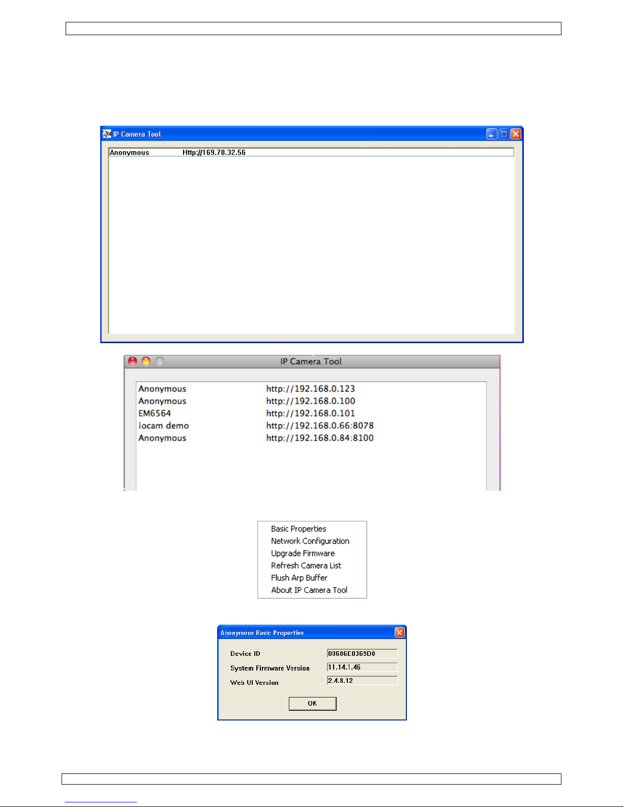
o Cameras are found and listed (see image below).
o Cameras are found but are not on the same subnet as the PC. The message ‘Subnet doesn’t
match, dbclick to change’ appears. Change the subnet settings via the network configuration
menu (see further).
Note: make sure DHCP is enabled in the router and MAC address filter is disabled. When
problems remain, disable any active firewall or antivirus and try again.
Windows:
Mac:
• Open the options menu by right clicking on a listed camera.
Note: only when the camera is fully initialised all options become visible.
Basic properties
• Shown some general information about the camera:
Network Configuration
• View/change the network settings of the camera:
Page 7

CAMIP5 Rev.01
27.10.2010 ©Velleman nv
7
• When connected to a DHCP router, check the ‘Obtain IP from DHCP server’ checkbox, otherwise
uncheck it and fill in the data manually.
• In case of a subnet mismatch, change the IP-address or subnet mask.
• When in doubt about the network settings, contact a qualified network administrator.
Upgrade firmware
• Only use this option when problems with the current version are noticed. Do not upgrade if the
camera works fine.
• Caution: when the upgrade process is interrupted or a wrong version is installed the camera
might not work anymore.
• The administrators’ login and password are required.
Note: default administrator login is admin without a password.
Refresh Camera List
• Use this option to update the camera list, e.g. when a new camera is added to the network.
Flush ARP Buffer
• When both a wireless and wired connection to a camera exists, a problem with the ARP (Address
Resolution Protocol) may arise resulting in the camera not being accessible via the browser. In
this case the ARP buffer should be cleared
About IP Camera Tool
• Show some extra information about the camera tool.
8.2 Camera login
• When the network set-up is completed, double click on the camera to open the camera window. A
web browser with a login page is opened:
Note: it is also possible to open a browser window and enter the cameras’ IP address in the
address bar.
Page 8

CAMIP5 Rev.01
27.10.2010 ©Velleman nv
8
• Enter your account name and password and click Login. Default, the administrator login is
admin without a password.
Note: use the upper Login button when your browser supports ActiveX Browser Plug-ins. When
using a browser that does not support ActiveX, click on the lower Login button. Some features
e.g. full screen, audio, multi-channel image … will not be available.
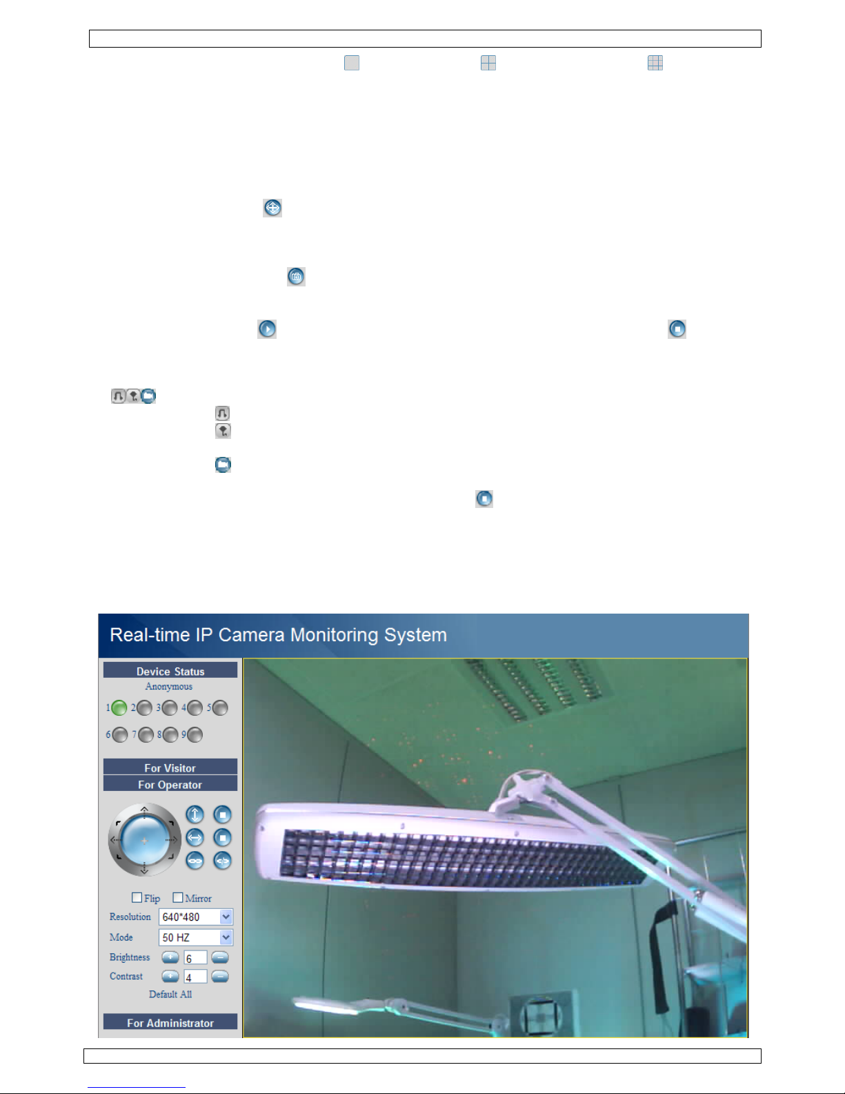
• When login on to the system with an administrator password, the For Operator screen opens,
otherwise the For Visitor layout will open.
For Visitor layout
• The interface software supports up to 9 cameras. The device status shows the status of each of
these 9 cameras. Green = OK, Yellow = camera connection problem, Red = alarm condition.
Page 9
CAMIP5 Rev.01
27.10.2010 ©Velleman nv
9
• Select the preferred screen layout: shows 1 camera, shows 4 cameras and shows 9
cameras simultaneously in the camera display pane.
• Set the preferred colour for the On Screen Display (OSD): disabled (no OSD), black, yellow, red,
white or blue. The OSD shows the name of the camera in the top right corner of the camera
display.
• When the ‘Add timestamp on record’ checkbox is checked, date and time is shown in the bottom
right corner of the camera display.
Note: set the time via the For Administrator screen (see further).
• Set the audio buffer. The speaker output will be delayed for the indicated number of seconds.
• Press the zoom button to open the camera display pane in full screen mode. A new browser
window is opened.
Note: to see a single camera display full screen, left double click on the desired camera display.
This also works in the For operator screen. Double click again to return to normal display.
• Press the snapshot button to take a snapshot of the camera display. In multiple screen
layouts, select the desired camera display first by left clicking on it. A new window with the
picture is opened. Press the Save button and select the desired location to save the picture.
• Press the view button to start viewing the camera images, press the stop button to stop
viewing.
• At the bottom of the left pane, each of the 9 possible cameras has 3 icons. Unavailable cameras
are greyed out.
= audio – talk – record
• Press on the icon to enable the cameras’ microphone
• Press on the icon to enable the cameras’ speaker/audio port; a PC microphone (not incl.) is
required.
• Press on the icon to start recording the selected cameras’ images.
Notes:
• When an icon is pressed, it changes to the stop icon . Press this icon to stop the underlying
function.
• The recorded file name is cameraname_timestamp.avi
e.g. Counter_20081211134442.avi
• The path where the movies will be stored can be set by the administrator in the For
Administrator screen (see further).
For Operator layout
Page 10
CAMIP5 Rev.01
27.10.2010 ©Velleman nv
10
• When entering an administrator password, the user can open the For Operator layout.
• In this layout, it is possible to pan/tilt the camera using the control panel:
Press on the arrows around the blue button to move in that
direction.
Press and hold to move faster.
Press in the centre to start auto-scanning the whole area.
auto tilt (vertical movement)
stop auto tilt
auto pan (horizontal movement)
stop auto pan
make alarm output [11.1] active.
deactivate alarm output
Note: when the camera is in auto tilt/auto pan mode, motion detection and external alarm input are
disabled!
• Check the Flip checkbox in case the image is shown upside down.
• Check the Mirror checkbox to mirror the image.
• Set the resolution to 320*240 or 640*480.
• Set the mode to 50Hz or 60Hz.
Note: the camera is not suitable for outdoor use! The outdoor setting could be used in case the
camera is pointed towards a bright natural light source.
• Set the brightness and contrast of the image with the “+” and “-” buttons.
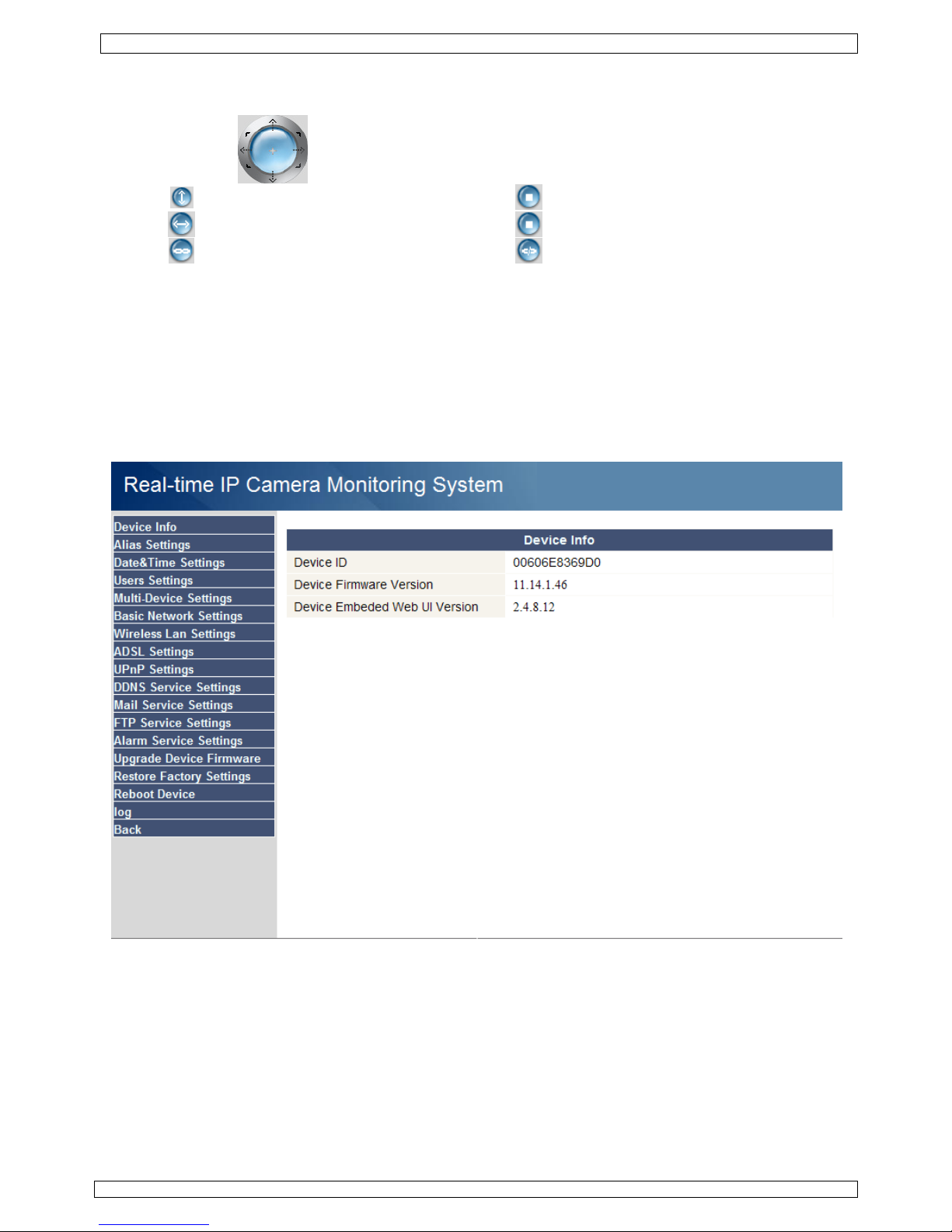
For Administrator layout
• The For Administrator layout is only available when logged in with an administrator account. It
is used for advanced configuration of the cameras.
Notes:
• Select the desired camera before opening the For Administrator layout.
• Depending on the ticked checkboxes, different data entry fields are shown. Hence the
display you see for a certain option might differ from the images used below.
Device info
• Device ID, firmware version and Web User Interface version are shown (see image above).
Page 11
CAMIP5 Rev.01
27.10.2010 ©Velleman nv
11
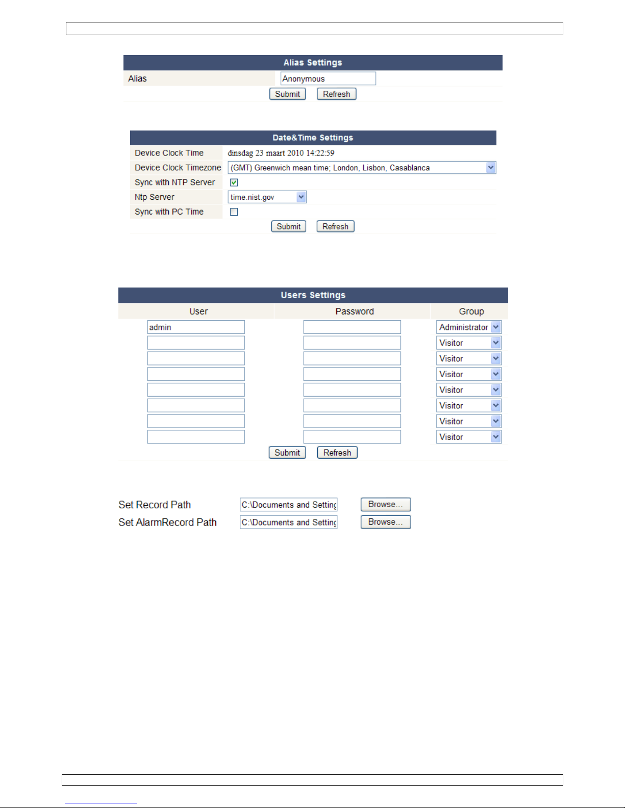
Alias Settings
• Set the name of the selected camera.
Date&Time Settings
• Set date and time data for the camera.
Note: if the timestamp on the display shows the wrong time, try checking the Sync with PC Time
checkbox and press Submit.
Users Settings
• Up to 8 users can be configured. Enter a user name, a password and select a group (Visitor,
Operator or Administrator). This is also the location to change the administrators’ login name and
set a password for the administrator.
• Set the record and alarm record paths using the Browse buttons. Default for both is
c:\\Documents and Settings\All Users\Documents
Notes when using Windows Vista,
• Remember to add the IP address of the camera to the ‘Trusted sites’.
• The system does not allow to set the Windows System Root Directory as record or alarm
record path.
Page 12
CAMIP5 Rev.01
27.10.2010 ©Velleman nv
12
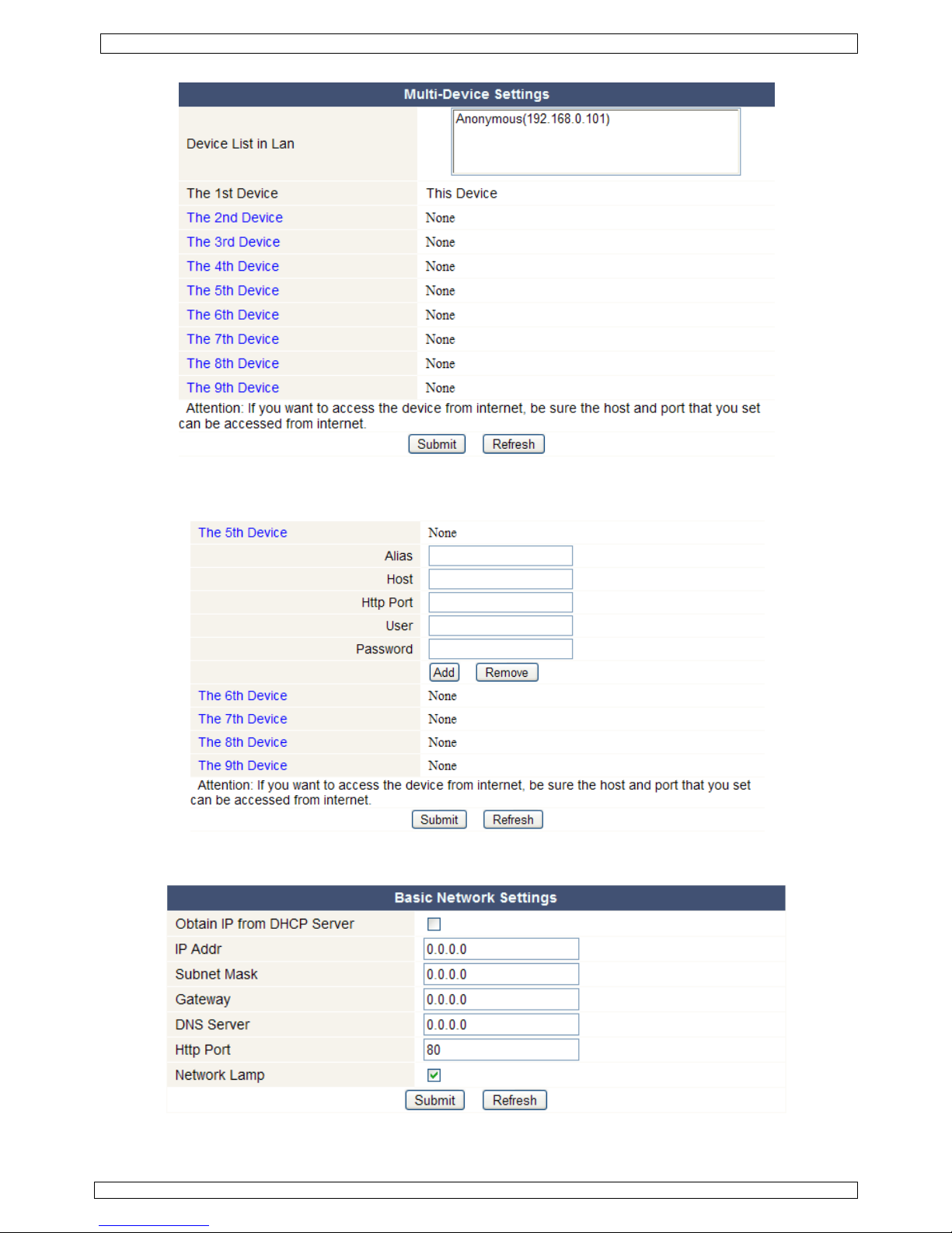
Multi-Device Settings
• Use this menu to manually add extra cameras (up to 9).
• Select a device by double clicking on it and enter an alias, host address, Http port, user name and
password:
• Press submit to add the device.
Basic Network Settings
• When connected to a DHCP router, check the ‘Obtain IP from DHCP server’ checkbox, otherwise
uncheck it and fill in the data manually.
Page 13

CAMIP5 Rev.01
27.10.2010 ©Velleman nv
13
• The ‘Network Lamp’ or network LED [5] indicates the network status of the camera. To disable
this LED, uncheck the ‘Network Lamp’ checkbox.
Wireless LAN Settings
• Press the Scan button to retrieve a list of available wireless LANs.
• Click on a found network and enter the password if required.
• When you want to use a wireless LAN, check the checkbox and enter a SSID, Channel and
encryption method. Depending on the selected encryption method, more data will have to be
provided.
Notes
• Some routers will automatically fill out the necessary data into the fields.
• When entering data manually, check the wireless net settings of your router to find more
information on SSID, Channel, encryption and authentication.
ADSL Settings
• When connected to the Internet directly via ADSL, check the checkbox and enter the ADSL User
name and ADSL password you obtained from your Internet Service Provider (ISP).
UPnP Settings
• Check the checkbox to use the Universal Plug and Play (UPnP) protocol
Page 14

CAMIP5 Rev.01
27.10.2010 ©Velleman nv
14
DDNS Service Settings
• Obtain a domain name from a supported DDNS provider (see image above) and enter the data in
the appropriate fields.
Mail Service Settings
Note: these settings only take effect when the option ‘Send Mail on Alarm’ is checked in the ‘Alarm
Service Settings’ menu (see below).
• Fill in a senders e-mail address in the ‘Sender’ field. This is the mailbox from which the mails will
be sent.
• Fill in up to 4 receivers mail addresses. When an alarm condition occurs, mail is sent out to these
addresses.
• Fill out all SMTP data related to the senders’ mail box. When authentication for the mailbox is
required, check the checkbox and enter user name and password in the appropriate fields.
• When the ‘Report Internet IP by Mail’ is checked, a mail is sent whenever a camera comes online
(e.g. after reboot) or a change in IP address occurred. Make sure the port is correctly mapped to
the router.
• Press ‘Submit’ to store the data before performing a ‘mail test’. Following error messages may
pop-up:
• Can not connect to the server
Check network cabling and settings.
• Network error. Please try later.
Check network cabling and settings.
• Server error.
Check the server.
Page 15
CAMIP5 Rev.01
27.10.2010 ©Velleman nv
15
• Incorrect user or password.
Make sure to enter the right user name and password.
• The sender is denied by the server.
Check whether the user needs authentication.
• The receiver is denied by the server.
Could be due to anti-spam settings of the server.
• The message is denied by the server.
Could be due to anti-spam settings of the server.
• The server does not support the authentication mode used by the device.
Try without authentication or use a different server (sender address).
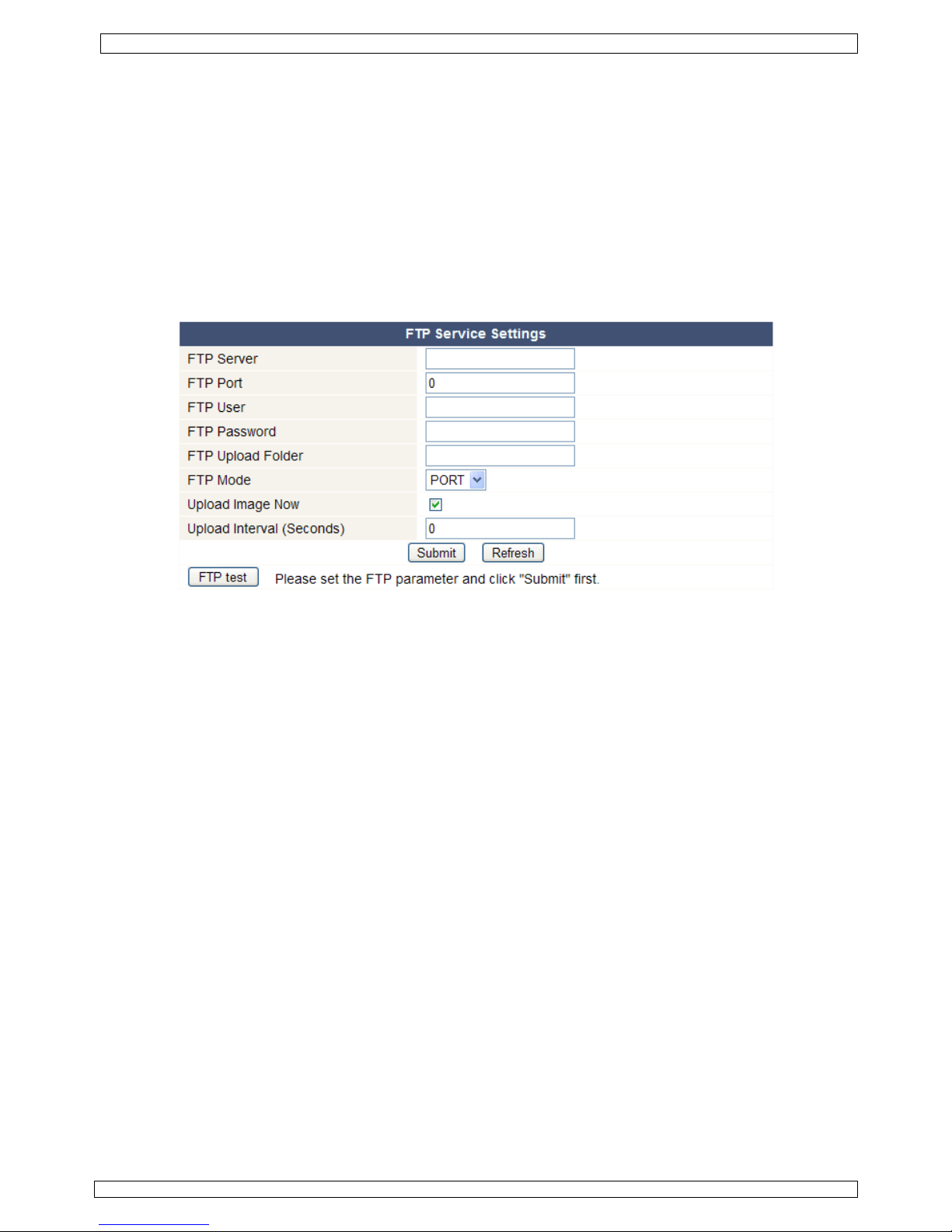
FTP Service Settings
Note: these settings only take effect when the option ‘Upload Image on Alarm’ is checked in the
‘Alarm Service Settings’ menu (see below).
• Fill out all FTP server data. The port is usually set to 21.
• Set the FTP mode to standard (PORT) or passive (PASV).
• When desired, check the ‘Upload Image Now’ checkbox and set an upload interval (in seconds).
• Press ‘Submit’ to store the data before performing an ‘FTP test’. A successful test will display ‘FTP
test succeeded’. Possible error messages are:
• Can not connect to server.
Check FTP server address
• Network error. Please try later.
Check network cabling and settings.
• Server error.
Check the FTP server
• Incorrect user or password.
Make sure to enter the right user name and password.
• Can not access the folder.
Make sure the folder exists and your FTP account is authorized.
• Error in PASV mode.
Make sure the server supports PASV mode.
• Error in PORT mode.
If the device is behind a NAT (Network Address Translation) device, PASV mode must
be selected.
• Can not upload file.
Make sure your FTP account is authorized.
Page 16

CAMIP5 Rev.01
27.10.2010 ©Velleman nv
16
Alarm Service Settings
• Check the ‘Motion Detect Armed’ checkbox to enable motion detection. This also allows mails to
be sent out (see Mail Service Settings) and image upload to an FTP server (see FTP Service
Settings).
Note: when the camera is in auto tilt/auto pan mode (see For Operator layout), motion
detection and external alarm input are disabled!
• The motion detect sensibility van be set between 1 and 10, with 10 being most sensitive.
• Check the ‘Alarm Input Armed’ checkbox when an external alarm sensor is connected to the
alarm input connectors [11.3] and [11.4].
• Check the ‘IO Linkage on Alarm’ checkbox to activate the alarm output connectors [11.1] and
[11.2]. When an external alarm output device (e.g. a buzzer, flash light…) is connected it will be
activated whenever an alarm condition is present.
• Check the ‘Send Mail on alarm’ checkbox to send a mail when an alarm is detected. Make sure to
fill out all fields on the ‘Mail Service Settings’ page (see above).
• Check the ‘Upload Image on alarm’ checkbox to upload images to an FTP server when an alarm is
detected. Make sure to fill out all fields on the ‘FTP Service Settings’ page (see above). When this
option is checked, you can also set the upload interval (in seconds).
• Check the ‘Scheduler’ checkbox to open the day schedule. Click on the schedule to set the time
during which alarm service must be enabled. Horizontal axis = hours, divided per 15 minutes and
Vertical axis = day of the week.
Upgrade Device Firmware
• Only use this option when problems with the current version are noticed. Do not upgrade if the
camera works fine.
• Caution: when the upgrade process is interrupted or a wrong version is installed the camera
might not work anymore.
• When clicking on Upgrade Device Firmware or Embedded Web UI (User Interface), a brower
window is opened. Locate and select the new firmware/web UI.
Page 17

CAMIP5 Rev.01
27.10.2010 ©Velleman nv
17
Restore Factory Settings
• Selecting ‘OK’ will clear the memory and reset the device to factory settings. All settings, e.g.
user settings, mail and FTP settings, alarm schedule… are lost.
Reboot Device
• Select ‘OK’ to reboot the camera.
Note: this will reset the system time. Refer to Date&Time settings.
Log
• The log shows an overview of everyone who accessed the IP camera. It is cleared when rebooting
the system.
Back
• Use this option to return to the For Visitor or For Operator page layout.
9. Additional user information
9.1 Password
• Default, the administrator login is admin without a password. To enhance security, a new
administrator password should be set as soon as possible (see §8.2 under For Administrator
layout – Users Settings).
• If the login or password of the administrator(s) are forgotten or corrupt, the system can be reset
to factory defaults (admin, no password) by pressing and holding the RESET button at the
bottom of the camera for about 5 seconds.
Page 18

CAMIP5 Rev.01
27.10.2010 ©Velleman nv
18
9.2 WiFi
• Refer to the user manual of your wireless router to obtain network information e.g. SSID,
Channel, Security, authentication, encryption…
• Use previously obtained information to configure your CAMIP5 via a fixed network cable (For
Administrator – Wireless LAN settings).
• Reboot the CAMIP5.
• Wait at least 30 seconds before unplugging the network cable. Then unplug the power supply.
• Re-insert the power plug.
• After about 30 seconds, the camera should be up and running in WiFi mode.
9.3 Connect the camera on an ADSL network
• Connect the camera to a PC. The easiest way is to use a router. If no router is available, you
must use a cross cable (not incl.) to connect the CAMIP5 directly to the PCs’ RJ45 port and set
the IP addresses on PC and camera manually.
• Configure the camera with the IP camera tool (see §8.1).
• Log on to the camera as administrator and configure ADSL settings (user name + password).
• Configure the DDNS Service Settings and click ‘Submit’. The camera reboots.
• Connect the camera directly to the ADSL modem. It is now available through the internet by
entering the domain name in your internet browser.
Note: set the option ‘Report ADSL IP by mail’ under Mail Service Settings to receive the
cameras’ IP address by mail.
9.4 Connect the camera via a router
• Connect the camera to the LAN and configure the camera with the IP camera tool (see §8.1).
• Log on to the camera as administrator and configure DDNS Service Settings.
• Click ‘Submit’ to reboot the camera.
• The camera is now available through the internet by entering the domain name in your internet
browser.
9.5 Static IP users
• When using only fixed IP addresses, a DDNS service is not required. There are two ways to find
out the static WAN IP address of the camera:
o Connect a computer to the same connection as the camera and open a website that tells you
what IP address you are on (e.g. www.whatismyip.com
).
o Log on to the router and view the status page to find out its WAN IP address. To connect to
the IP camera, enter the WAN IP address of the router followed by the port number to which
the camera is connected into the address bar of a browser (e.g. http://116.25.51.115:85/).
Make sure UPnP is enabled or the camera is added to the routers’ virtual mapping list.
9.6 Using DDNS
• DDNS stand for Dynamic Domain Name Server. It is a service that links dynamic IP addresses to
fixed domain names. This way, the camera will always be accessible by using a domain name, no
matter which IP address was assigned to it.
• To obtain a domain name and password, refer to a DDNS website on the internet.
• Enter the name and password in the DDNS Service Settings page and press ‘Submit’. The
camera reboots.
• Check the UPnP settings. If the status is not ‘succeed’, try to change the port number in the
Basic Network Settings page. Submit and reboot the camera.
• To connect to the camera, enter domain name of the camera in the address bar of a web
browser. The prefix www. is not required. When multiple cameras are connected to the router,
add the port number behind the domain name (e.g. http://ipcam. Video.net:85/)
Page 19

CAMIP5 Rev.01
27.10.2010 ©Velleman nv
19
9.7 Using a mobile phone
• When the camera is on a WAN, it is possible to connect to it using a midp2.0 java mobile
phone.
• Copy IPCamera.jar from the CD ROM to the phone and install it.
• Run IP camera player.
• Enter alias, hostname or IP, port, user, password and resolution, than click OK.
• Controls are:
2 move up 8 move down
4 move left 6 move right
1 auto pan start 3 auto pan stop
7 auto tilt start 9 auto tilt stop
10. Troubleshooting
IP address
• Always make sure the camera is on the same subnet (same subnet mask) as the PC you are
using to configure it
Network configuration
• Check your HTTP server software is configured and running properly.
• If the camera is behind a firewall, make sure the firewall software is allowing inbound connections
on port 80. If not, use an alternate port. The same goes for certain anti-spam and anti-virus
software packages.
• If the camera is behind a cable/DSL router, make sure to configure port forwarding properly.
Refer to the user manual of the router.
No image
• Video streaming is transmitted by the ActiveX controller. If this controller is not installed properly
no video image is shown.
• When you install the IP Camera Tool, the ActiveX controller is installed at the same time.
Otherwise, download the ActiveX controller from the internet and set the safety properties of your
web browser so it accepts ActiveX content.
Slow image
• The frame rate of the shown video depends on a number of external factors, e.g.:
o Network bandwidth
o PC performance and display settings
o Number of visitors that are viewing the camera simultaneously
o Network equipment (e.g. use a switch in stead of a HUB for multiple IP cameras)
Camera not available via Internet
• Possible reasons may include:
o ActiveX controller is not installed/working properly.
Note: a standard Firefox browser does not support ActiveX. However there are plug-inns
available on the Internet.
o The port of the IP camera is blocked by a firewall or anti-virus software. In this case, try
using a different port number.
o Port mapping failed. Either enable UPnP (via UPnP Settings) or edit the routers Virtual
map list (refer to the user manual of your router).
Page 20

CAMIP5 Rev.01
27.10.2010 ©Velleman nv
20
11. Technical specifications
sensor ¼" colour CMOS sensor
lens 3.6mm / F2.4
minimum illumination 0.5 lux (IR LEDs off)
resolution 640 x 480 pixels (300 000 pixels)
built-in pan/tilt controllable through internet
left/right 270°
up/down 120°
supported network protocols
TCP/IP, UDP, IMCP, SMTP, HTTP, FTP, DNS, DDNS,
DHCP, PPPoE
wired connection Ethernet 10/100 Base-T and RJ45
wireless connection
standard IEEE 802.11b/g
supports WEP, WPA & WPA2 encryption
network connection
supports 3 methods fixed IP, DHCP, PPPoE
supports DHCP, installs the IP address automatically
(plug-and-play network)
audio built-in microphone
video compression format MJPEG
frame rate 15 FPS (VGA), 30 FPS (QVGA)
resolution 640 x 480 (VGA), 320 x 240 (QVGA)
dimensions 110 x 100 x 108mm
weight ±768g
Use this device with original accessories only. Velleman nv cannot be held responsible in
the event of damage or injury resulted from (incorrect) use of this device. For more info
concerning this product and the latest version of this user manual, please visit our
website www.velleman.eu. The information in this manual is subject to change without
prior notice.
© COPYRIGHT NOTICE
The copyright to this manual is owned by Velleman nv. All worldwide rights reserved.
No part of this manual or may be copied, reproduced, translated or reduced to any electronic
medium or otherwise without the prior written consent of the copyright holder.
Page 21

27
1
.
A
aBeHeDahe
2
.3.
R
a• L• O
g• G
g• D
e
r
4
.
•
e
•
p
•
b• n
• i
•
a
5
.
R
a
1
2
3
4
5
6
.10.2010
Inleidi
n
n alle in
g
langrijke
Dit
woreveges
of
n
bt u vrag
nk u voor
t toestel b
e
Veiligh
e
Ho
El
e
str
orep
D
ever
uw
Algem
e
adpleeg d
e
eer eerst
d
m veiligh
e
ebruiker
h
ebruik he
t
arantie.
e garanti
e
n uw deal
e
echtstree
k
Eigens
c
envoudig
t
an- en tilt
eveiligde
W
achtzicht
d
ngebouwd
e
larmberic
h
Omsch
r
adpleeg d
e
lichtsen
infraro
o
lens
luidspr
e
netwer
k
microfo
o
ezetenen
milieu-in
f
symbool o
dt wegge
w
ntuele bat
t
pecialisee
r
aar een lo
en, conta
c
uw aanko
o
schadigd
t
idsinst
r
ud buiten
h
ktrocutie
om staan
araties ov
e
behuizin
g
vangbare
o
dealer.
ne richt
Vellema
n
Enkel
v
opspatt
e
Besche
r
Besche
r
e functies
idsredene
n
eeft aang
e
toestel e
n
geldt niet
r zal de v
e
s verband
happen
e installer
e
beweging
o
i-Fi-aans
l
ankzij 10
microfoo
n
t bewegin
g
ijving
afbeeldin
g
sor
dleds (10
x
ker
led
n
GE
B
van de E
u
ormatie
b
p het toes
t
orpen, dit
erijen) ni
e
d bedrijf t
e
kaal recycl
teer dan
p! Lees de
z
ijdens het
ucties
et bereik
v
gevaar bij
om dodelij
r aan ges
c
mag NO
O
nderdele
n
lijnen
®
servic
e
oor gebr
u
nde vloei
s
m tegen s
t
m tegen s
c
van het t
o
mag u g
e
bracht val
t
kel waarv
o
voor scha
d
rantwoor
d
mee houd
e
n
p afstand
uiting en
b
infraroodl
e
en luidsp
swaarne
m
en op pa
g
)
RUIK
E
ropese U
n
etreffen
d
el of de ve
toestel sc
h
t bij het g
e
rechtkom
e
agepunt b
r
de plaats
e
e handlei
d
transport,
an kinder
e
het opene
ke elektro
s
hoold per
s
IT geop
e
in dit toe
s
- en kwal
ik binne
n
toffen.
of en extr
e
hokken e
n
estel kenn
e
en wijzigi
n
niet onde
r
or het ge
m
e door he
t
elijkheid a
f
n.
ekabelde
L
ds
reker
ing via e-
m
ina 2 van
d
CAMIP5
21
RSHA
N
ie
e dit pro
d
rpakking g
e
ade kan t
o
wone huis
n voor rec
y
engen. Re
s
lijke aut
o
ing grondi
installeer
h
n en onbe
v
n van het
t
hocks te
v
oneel.
nd word
e
tel. Voor o
iteitsgara
shuis. Be
s
me hitte.
vermijd b
r
n voor u
h
gen aanbr
e
de garan
t
aakt is. B
i
negeren
v
wijzen vo
o
AN-aanslu
ail of upl
o
eze handl
e
7
W8 a9 R
10
a
11
i
12
5
DLEID
I
uct
eft aan d
a
ebrengen
a
houdelijke
clage. U
m
pecteer d
e
riteiten
b
g voor u h
e
et dan nie
oegden.
oestel. Ra
a
ermijden.
O
n. Er zijn
g
nderhoud
o
ntie achte
r
cherm teg
e
ute krach
t
et gaat ge
ngen. Sc
h
ie.
j onoorde
e
an bepaal
d
r defecten
iting
ad van be
e
iding.
i-Fi-ante
n
udio-uitg
a
J45-aansl
ntenneaa
n
n-/uitgang
VDC ing
a
NG
t, als het
n
an het mi
afval; het
oet dit to
e
plaatselij
k
etreffen
d
t toestel i
n
t en raadpl
k geen ka
pen de b
e
een door
d
f reserveo
aan deze
h
n regen,
v
tijdens de
bruiken.
ade door
w
lkundig ge
e richtlijn
e
of proble
m
lden naar
ne
ng
uiting
sluiting
saansluitin
ngsaanslui
a zijn lev
e
lieu. Gooi
d
moet bij e
e
stel naar
u
e milieuw
e
e de ver
w
gebruik
n
eeg uw de
a
bels aan di
huizing ni
e
e gebruik
e
nderdelen,
andleidin
g
ochtighei
d
bediening
ijzigingen
bruik verv
a
n in deze
en die hie
FTP
g alarm
ting (2 A)
Rev
.
©Vellema
n
nscyclus
it toestel
(
n
w verdele
r
tgeving.
ijdering.
eemt. We
r
ler.
e onder
t zelf en l
a
r
contactee
r
.
en
.
die de
lt de
handleidin
g
r
01
nv
en
d
at
Page 22

CAMIP5 Rev.01
27.10.2010 ©Velleman nv
22
11.1 +5VDC-uitgang 11.3 alarmingang
11.2 uitgang (GND) 11.4 ingang (GND)
6. De hardware installeren en gebruiken
• Kies een geschikte montageplaats voor de camera en houd rekening met volgende punten:
• monteer de camera nooit op een plaats onderhevig aan extreme temperaturen en trillingen;
• monteer de camera nooit in de buurt van elektromagnetische velden;
• richt de camera nooit naar de zon of naar andere weerkaatsende objecten toe;
• De camera is geschikt voor alleenstaand gebruik of voor muur-/plafondmontage dankzij de
meegeleverde beugel en de twee schroeven. Bevestig de camera aan de montagebeugel met de
centrale schroef. Richt de camera.
• Steek de antenne in de aansluiting [7] en/of steek de meegeleverde netwerkkabel in de RJ45-
aansluiting [9].
Opmerking: U kunt de camera rechtstreeks op de RJ45-aansluiting van de computer aansluiten.
Gebruik hiervoor een gekruiste kabel (niet meegeleverd). De camera moet daarna
handmatig ingesteld worden.
• Alarmaansluiting:
• Sluit een externe sensor, bv. een PIR-sensor, aan op de alarmingang [11.3] en de GND-ingang
[11.4].
• Sluit een alarmtoestel, bv. een sirene, aan op de 5VDC-uitgang [11.1] en de GND-uitgang
[11.2]. Bij alarm zal uitgang [11.1] inschakelen.
Opmerking: U kunt de uitgang ook inschakelen met en onder ‘For Operator’ (zie verder).
• Sluit indien gewenst een externe luidspreker aan op de audio-uitgang [8].
• Steek de voedingsstekker van de voedingsadapter in de 5VDC-ingang [12]. Gebruik enkel de
meegeleverde adapter of een adapter met dezelfde eigenschappen.
• Steek de voedingsadapter in het stopcontact (100 ~ 240 VAC/50 ~ 60 Hz).
Opmerkingen:
• De initialisatie van de camera duurt een 30-tal seconden.
• Tijdens de initialisatie beweegt de camera om de pan- en tiltbewegingen te testen.
• Regel de lens [3] bij indien u een onscherp beeld krijgt.
7. De software installeren
• Steek de meegeleverde cd-rom in de cd-romdrive van uw computer.
Systeemvereisten: CPU ≥ 2,06 GHz / geheugen ≥ 256 MB / netwerk ≥ 10 MB / grafische kaart
≥ 64 MB / aanbevolen besturingssysteem: Windows 2000 of XP / Mac.
Windows
• Dubbelklik op IPCamSetup.exe om de software te installeren.
Page 23

CAMIP5 Rev.01
27.10.2010 ©Velleman nv
23
• Volg de instructies op het scherm. Klik op Next om de installatie te starten.
• Klik opnieuw op Next.
• Herstart de computer om de installatie te voltooien. Vink Yes I want to restart my computer
now aan en klik op Close.
• Na de herstart verschijnt IP Camera Tool op het bureaublad.
Mac
• Open de folder “For MAC”.
• Open de folder “IP camera Tool “ en kopieer de tool naar uw Mac.
8. De software configureren
• Dubbelklik op IP Camera Tool om de software te starten.
8.1 IP Camera Tool
• De software zoekt automatisch naar de beschikbare camera’s op het LAN-netwerk. Er zijn 3
mogelijkheden:
o Er zijn geen camera’s beschikbaar. Controleer de bekabeling en zorg dat de camera is
ingeschakeld indien de software na 1 minuut geen enkele camera heeft gevonden.
Page 24

CAMIP5 Rev.01
27.10.2010 ©Velleman nv
24
o Er zijn camera’s beschikbaar en ze staan opgelijst (zie afbeelding hieronder).
o Er zijn camera’s beschikbaar maar ze staan niet op hetzelfde subnet als deze van uw computer.
Het bericht Subnet doesn’t match, dbclick to change verschijnt. Wijzig de configuratie van
het subnet via het configuratiemenu van het netwerk (zie verder).
Opmerking: Zorg dat het DHCP in de router ingeschakeld is en de MAC-adresfiltering
uitgeschakeld is. Bij blijvende problemen, schakel alle actieve firewalls of antivirussoftware uit en
probeer opnieuw.
Windows:
Mac:
• Open het optiemenu door met de rechtermuisknop op een camera in de lijst te klikken.
Opmerking: De opties zijn enkel zichtbaar na de volledige initialisatie van de camera.
Basiseigenschappen (Basic properties)
• Algemene informatie over de camera:
Netwerkconfiguratie (Network Configuration)
• Een overzicht van de netwerkinstellingen van de camera:
Page 25

CAMIP5 Rev.01
27.10.2010 ©Velleman nv
25
• Vink Obtain IP from DHCP server aan indien aangesloten op een DHCP-router. Indien niet, vink
uit en geef de data handmatig in.
• Wijzig het IP-adres of het subnetmasker bij een ongeldig subnetadres.
• Neem bij twijfel over de subnetinstellingen contact op met een netwerkbeheerder.
De firmware upgraden (Upgrade firmware)
• Het is aanbevolen om de firmware te upgraden enkel en alleen indien u problemen ondervindt met
de huidige versie. U hoeft de de firmware niet te upgraden indien de camera normaal functioneert.
• Opgelet: U kunt de camera ernstig beschadigen indien het upgradeproces onderbroken wordt of
een verkeerde versie wordt geïnstalleerd.
• Geef de login en het wachtwoord van de beheerder in.
Opmerking: De standaard login is admin zonder wachtwoord.
De cameralijst verversen (Refresh Camera List)
• Ververs de lijst wanneer u een nieuwe camera aan het netwerk toevoegt.
ARP-buffer wissen (Flush ARP Buffer)
• Bij zowel een draad- als een draadloze aansluiting kunnen zich problemen voordoen met het ARP
(Address Resolution Protocol) en kan de camera via de browser niet beschikbaar zijn. Wis in dit
geval de ARP-buffer.
Over de camera (About IP Camera Tool)
• Bijkomende informatie over de camera.
8.2 Login van de camera
• Dubbelklik na de volledige configuratie van het netwerk op de camera. Er verschijnt een
webbrowser met aanmeldpagina:
Opmerking: U kunt het IP-adres van de camera ook in de adresbalk van een webbrowser
ingeven.
Page 26

CAMIP5 Rev.01
27.10.2010 ©Velleman nv
26
• Geef uw accountnaam en wachtwoord in en klik daarna op Login. De standaard login is admin
zonder wachtwoord.
Opmerking: Gebruik de aanmeldknop bovenaan indien uw browser ActiveX gebruikt. Gebruikt u
een browser dat ActiveX niet ondersteunt, klik dan op de onderste aanmeldknop.
Merk op dat sommige functies zoals een volledige schermweergave en een audio dan
niet beschikbaar zijn.
• Bij het inloggen zonder wachtwoord verkrijgt u toegang tot het bezoekersmenu For Visitor.
For Visitor (bezoeker)
• De software ondersteunt tot 9 camera’s. Onder Device Status ziet u de status van elke
aangesloten camera: groen = oké, geel = aansluitingprobleem, rood = alarm.
• Kies de gewenste schermlay-out: = 1 camera, = 4 camera’s, = 9 camera’s.
Page 27

CAMIP5 Rev.01
27.10.2010 ©Velleman nv
27
• Kies de gewenste kleur voor het OSD-menu: disabled (geen OSD), zwart, geel, rood, wit of blauw.
De OSD geeft de cameranaam rechtsboven het scherm weer.
• Vink Add timestamp on record aan om datum en tijd onderaan rechts weer te geven.
Opmerking: Stel de tijd in via het For Administrator-menu (zie verder).
• Stel de audiobuffer in. De luidspreker wordt gedurende het aantal ingestelde seconden
uitgeschakeld.
• Druk op (zoom) voor een volledige schermweergave. Er verschijnt een nieuw browservenster.
Opmerking: Dubbelklik op de gewenste camera om deze op het volledige scherm weer te geven.
Dubbelklik opnieuw om naar de normale weergave terug te keren.
• Druk op voor een screenshot. Selecteer eerst de gewenste camera door met de linkermuisknop
op de beeldweergave te klikken. Er verschijnt een nieuw scherm met daarin de screenshot. Druk
op Save en selecteer de doelmap om de screenshot te bewaren.
• Druk op om de beeldweergave van een camera in te schakelen of op om de beeldweergave
uit te schakelen.
• Onderaan het linkerpaneel vindt u voor de 9 camera’s telkens 3 iconen: = audio – spraak –
opname. Niet-beschikbare camera’s zijn wazig gemaakt.
• Schakel de microfoon van de camera in met .
• Schakel de luidspreker van de camera in met . Voor deze functie moet u een microfoon (niet
meegeleverd) op uw computer aansluiten.
• Druk op om de opnamefunctie voor die camera in te schakelen.
Opmerkingen:
• Bij het aanklikken van een icoon verandert de icoon . Druk op deze icoon om zijn functie uit
te schakelen.
• De bestandsnaam van de opname wordt cameranaam_tijdsaanduiding.avi.
Bv. ingang_20081211134442.avi.
• Het pad waaronder de opnames bewaard worden, zijn door de beheerder onder For
Administrator instelbaar (zie verder).
For Operator (gebruiker)
• Bij het inloggen met wachtwoord verkrijgt u toegang tot het gebruikersmenu For Operator.
• Hier kunt u de camera ook bedienen:
Page 28

CAMIP5 Rev.01
27.10.2010 ©Velleman nv
28
Verplaats de camera met de pijltjes.
Houd ingedrukt om de camera sneller te verplaatsen.
Druk op de blauwe knop in het midden om de zone
automatisch af te scannen.
auto tilt (verticale beweging)
stop auto tilt
auto pan (horizontale beweging)
stop auto pan
alarmuitgang activeren [11.1]
alarmuitgang deactiveren
Opmerking: Tijdens het automatisch afscannen, zijn de bewegingswaarneming en de externe
alarmingang uitgeschakeld!
• Vink Flip aan om het beeld om te draaien.
• Vink Mirror om het beeld te spiegelen.
• Stel de resolutie in op 320*240 of 640*480.
• Stel de snelheid in op 50 Hz of 60 Hz.
Opmerking: Deze camera is niet geschikt voor gebruik buitenshuis! Gebruik de instellingen voor
buitenshuis indien de camera naar een heldere lichtbron is gericht.
• Stel helderheid en contrast van het beeld in met + en –.
For Administrator (beheerder)
• Het beheerdermenu For Administrator is enkel beschikbaar indien u inlogt met
beheerderwachtwoord. Dit menu beschikt over geavanceerde instelmogelijkheden.
Opmerkingen:
• Kies de gewenste camera alvorens het beheerdermenu te openen.
• Verscheidene invoervelden zijn beschikbaar naargelang de aangevinkte vakjes. De afbeeldingen
hieronder kunnen dus verschillen met de werkelijkheid.
Cameragegevens (Device info)
• ID-nummer, versie van de firmware en van de gebruikersinterface (zie afbeelding hierboven).
Aliasinstellingen (Alias Settings)
• Geef hier de naam van de camera in.
Page 29

CAMIP5 Rev.01
27.10.2010 ©Velleman nv
29
Datum- en tijdsinstellingen (Date&Time Settings)
• Stel hier datum en tijd in.
Opmerking: Vink Sync with PC Time aan en druk op Submit bij een verkeerde tijdsaanduiding
op de display.
Gebruikersinstellingen (Users Settings)
• Als beheerder kunt u tot 8 gebruikers beheren. Geef gebruikersnaam en wachtwoord in en
selecteer een groep (Visitor, Operator of Administrator). Hier kunt u ook uw aanmeldnaam en
wachtwoord wijzigen.
• Stel het opname- en alarmpad in met Browse. Standaard is dit pad C:\Documents and
Settings\All Users\Documents.
Opmerkingen voor Windows Vista
®
-gebruikers:
• Geef ook het IP-adres in van vertouwde websites.
• U kunt de Windows-rootfolder niet als opname- of alarmpad instellen.
Instellingen voor meerdere camera’s (Multi-Device Settings)
Page 30

CAMIP5 Rev.01
27.10.2010 ©Velleman nv
30
• Gebruik dit menu om handmatig tot 9 camera’s toe te voegen.
• Selecteer een camera door deze te dubbelklikken en een alias, een bezoekersadres, een http-
poort, een gebruikersnaam en een wachtwoord in te geven:
• Druk op Submit om de camera toe te voegen.
Basisinstellingen van het netwerk (Basic Network Settings)
• Vink Obtain IP from DHCP server aan indien aangesloten op een DHCP-router. Indien niet, vink
uit en geef de gegevens handmatig in.
• Network Lamp geeft de status van de camera in het netwerk weer. Vink uit om de led [5] uit te
schakelen.
Instellingen draadloos LAN
• Druk op Scan om een lijst weer te geven van alle beschikbare draadloze LAN-netwerken.
• Klik op het beschikbare netwerk en geef indien nodig het wachtwoord in.
• Vink Using Wireless Lan aan en geef een SSID, het kanaal en de encryptie in indien u een
draadloos LAN-netwerk wenst te gebruiken. U zult meer gegevens moeten ingeven afhankelijk van
de geselecteerde encryptie.
Opmerkingen:
• Bepaalde routers geven automatisch de nodige gegevens in.
Page 31

CAMIP5 Rev.01
27.10.2010 ©Velleman nv
31
• Raadpleeg de draadloze netwerkinstellingen van de router voor meer informatie over SSID,
kanaal, encryptie en authenticatie bij een handmatige invoer van de gegevens.
ADSL-instellingen (ADSL Settings)
• Vink aan en geef gebruikersnaam en ADSL-wachtwoord in bij aansluiting via ADSL. Deze gegevens
zijn verkrijgbaar bij uw internetprovider.
UPnP-instellingen (UPnP Settings)
• Vink aan om het UPnP-protocol (Universal Plug and Play) te gebruiken.
Instellingen DDNS Service (DDNS Service Settings)
• Vraag een domeinnaam aan bij uw DDNS-provider (zie afbeelding hieronder) en geef de gegevens
in de daartoe bestemde velden in.
E-mailinstellingen (Mail Service Settings)
Page 32

CAMIP5 Rev.01
27.10.2010 ©Velleman nv
32
Opmerking: Deze instellingen zijn enkel geldig indien de optie Send Mail on aangevinkt is in het
menu Alarm Service Settings (zie hieronder).
• Geef het adres in van de afzender in het veld Sender. Dit is de mailbox waaruit de e-mails worden
verzonden.
• U kunt tot 4 ontvangadressen ingeven. Bij alarm wordt een e-mail naar elk van de ingegeven
adressen verzonden.
• Geef alle SMTP-gegevens in. Bij authenticatie van de mailbox, vink het vakje aan en geef
gebruikersnaam en wachtwoord in.
• Vink Report Internet IP by Mail aan om een e-mail te krijgen van zodra de camera online
beschikbaar is (bv. na een herstart) of bij wijziging van het IP-adres.
• Druk op Submit om de gegevens te bewaren alvorens het systeem te testen. Volgende
foutmeldingen zijn mogelijk:
• Geen aansluiting met de server.
Controleer de bekabeling en de instellingen van het netwerk.
• Netwerkfout. Probeer het later opnieuw.
Controleer de bekabeling en de instellingen van het netwerk.
• Serverfout.
Controleer de server.
• Gebruikersnaam of wachtwoord niet correct.
Geef uw gebruikersnaam en wachtwoord correct in.
• Afzender geweigerd door de server.
Controleer of de gebruiker authenticatie hoeft.
• Bestemmeling geweigerd door de server.
Controleer de antispaminstellingen van de server.
• Bericht geweigerd door de server.
Controleer de antispaminstellingen van de server.
• De server ondersteunt geen authenticatie.
Probeer zonder authenticatie of gebruik een andere server.
Instellingen FTP Service (FTP Service Settings)
Opmerking: Deze instellingen zijn enkel geldig indien de optie Upload Image on Alarm
aangevinkt is in het menu Alarm Service Settings (zie hieronder).
• Geef alle FTP-gegevens in. De FTP-poort is doorgaans 21.
• Stel FTP Mode in op standaard (PORT) of passief (PASV).
• Indien gewenst, vink Upload Image Now aan en stel een interval in (in seconden).
• Druk op Submit om de gegevens te bewaren alvorens het systeem te testen. Volgende
foutmeldingen zijn mogelijk:
• Geen aansluiting met de server.
Controleer het adres van de FTP-server.
• Netwerkfout. Probeer het later opnieuw.
Controleer de bekabeling en de instellingen van het netwerk.
• Serverfout.
Controleer de FTP-server.
• Gebruikersnaam of wachtwoord niet correct.
Geef uw gebruikersnaam en wachtwoord correct in.
Page 33

CAMIP5 Rev.01
27.10.2010 ©Velleman nv
33
• Toegang tot de map geweigerd.
Zorg ervoor dat de map bestaat en dat uw FTP-account toegang heeft.
• Fout in PASV-modus.
Zorg ervoor de server de PASV-modus ondersteunt.
• Fout in PORT-modus.
Selecteer de PASV-modus indien uw router zich achter een NAT (Network Address
Translation) bevindt.
• Upload van het bestand geweigerd.
Zorg ervoor dat uw FTP-account toegang heeft.
Alarminstellingen (Alarm Service Settings)
• Vink Motion Detect Armed aan om de bewegingswaarnemingfunctie in te schakelen. Hierdoor
zult u ook e-mails ontvangen (zie: E-mailinstellingen) en beelden naar een FTP-server kunnen
uploaden (zie: Instellingen FTP Service).
Opmerking: Tijdens het automatisch afscannen (zie: For Operator), zijn de
bewegingswaarneming en de externe alarmingang uitgeschakeld!
• Stel de gevoeligheid van de sensor in tussen 1 en 10 (10 = hoogste gevoeligheid).
• Vink Alarm Input Armed aan indien u een externe sensor aan ingangen [11.3] en [11.4] hebt
aangesloten.
• Vink IO Linkage on Alarm aan om alarmuitgang [11.1] en [11.2] in te schakelen. Sluit op deze
uitgangen een sirene of zwaailicht aan om deze bij alarm in te schakelen.
• Vink Send Mail on alarm aan om een e-mail te versturen bij alarm. Vul alle gegevens in onder
Mail Service Settings (zie hierboven).
• Vink Upload Image on alarm aan om beelden te uploaden naar een FTP-server bij alarm. Vul
alle gegevens in onder FTP Service Settings (zie hierboven). Indien u deze functie inschakelt,
dan kunt u ook het uploadinterval instellen (in seconden).
• Vink Scheduler aan om het programmeermenu te openen. Programmeer de tijdruimte waarin u
de bewegingswaarnemingfunctie wenst in te schakelen: horizontale as = uren per 15 minuten,
verticale as = weekdag.
Page 34

CAMIP5 Rev.01
27.10.2010 ©Velleman nv
34
Upgrade van de firmware (Upgrade Device Firmware)
• Het is aanbevolen om de firmware te upgraden enkel en alleen indien u problemen ondervindt met
de huidige versie. U hoeft de de firmware niet te upgraden indien de camera normaal functioneert.
• Opgelet: U kunt de camera ernstig beschadigen indien het upgradeproces onderbroken wordt of
een verkeerde versie wordt geïnstalleerd.
• Klik op Upgrade Device Firmware of Upgrade Device Embedded Web UI om een zoekvenster
te openen.
Fabrieksinstellingen herstellen (Restore Factory Settings)
• Klik op OK om het geheugen te wissen en om de camera te resetten. Alle gebruikers-, -email-,
alarm- en FTP-instellingen worden gewist.
Herstart (Reboot Device)
• Klik op OK om de computer te herstarten.
Opmerking: Uur en datum worden gewist (zie: Datum- en tijdsinstellingen).
Inloglijst (Log)
• De lijst geeft een volledig overzicht van de gebruikers die toegang hebben gehad tot de IP-
camera. De lijst wordt gewist na het resetten.
Terug (Back)
• Klik op deze knop om terug te keren naar For Visitor of For Operator.
Page 35

CAMIP5 Rev.01
27.10.2010 ©Velleman nv
35
9. Bijkomende gebruikersinformatie
9.1 Wachtwoord
• De standaard login is admin zonder wachtwoord. Stel onmiddellijk een nieuw wachtwoord in om
ongewenste toegang tot de camera te vermijden (zie: §8.2 For Administrator –
Gebruikersinstellingen).
• Bij verlies of corruptie van aanmeldnaam en/of wachtwoord kunt u de fabrieksinstellingen
herstellen (admin, geen wachtwoord) door RESET onderaan de camera gedurende 5 seconden
ingedrukt te houden.
9.2 Wi-Fi
• Raadpleeg de gebruikershandleiding van uw draadloze router voor meer informatie over SSID,
kanaal, beveiliging, authenticatie, encryptie…
• Gebruik deze gegevens om uw camera in te stellen via een vaste netwerkkabel (For
Administrator – Instellingen draadloos LAN).
• Herstart de camera.
• Wacht minstens 30 seconden alvorens de netwerkkabel uit de camera te trekken. Trek daarna ook
de voedingsstekker uit de camera.
• Steek de voedingsstekker opnieuw in de camera.
• Na een 30-tal seconden functioneert de camera in Wi-Fi-modus.
9.3 Aansluiting op een ADSL-netwerk
• Sluit de camera aan op een computer. De gemakkelijkste manier is met behulp van een router.
Hebt u geen router, gebruik dan een gekruiste kabel (niet meegeleverd) om de camera aan te
sluiten op de RJ45-poort van de computer en de IP-adressen op de computer en camera
handmatig in te stellen.
• Stel de camera in onder IP Camera Tool (zie: §8.1).
• Meld u aan op de camera als beheerder en stel de ADSL-instellingen in (gebruikersnaam en
wachtwoord).
• Stel de DDNS-instellingen in en klik op Submit. De camera wordt herstart.
• Sluit de camera aan op de ADSL-modem. De camera is nu beschikbaar via het internet door de
domeinnaam in de internetbrowser in te geven.
Opmerking: Vink Report ADSL IP by mail aan onder E-mailinstellingen om het IP-adres van
de camera via e-mail te ontvangen.
9.4 Aansluiting via een router
• Sluit de camera aan op het LAN-netwerk en stel de camera in onder IP Camera Tool (zie: §8.1).
• Meld u aan op de camera als beheerder en stel de DDNS-instellingen in.
• Klik op Submit om de camera te herstarten.
• De camera is nu beschikbaar via het internet door de domeinnaam in de internetbrowser in te
geven.
9.5 Statische IP-gebruikers
• Bij gebruik van vaste IP-adressen is een DDNS-service niet noodzakelijk. Er zijn 2 manieren om
statische WAN IP-adres van de camera te zoeken:
o Sluit een computer aan op dezelfde aansluiting als die van de camera en open een
gespecialiseerde website die u het gebruikte IP-adres weergeeft (bv. www.whatismyip.com
).
o Meld u aan op de router en raadpleeg het WAN IP-adres van de statuspagina. Om de camera aan
te sluiten, geef het WAN IP-adres van de router in gevolgd door het poortnummer waarop de
camera is aangesloten in de adresbalk van een browser (bv. http://116.25.51.115:85/). Schakel
de UPnP-functie in.
9.6 Gebruik van DDNS
• DDNS (Dynamic Domain Name Server) is een service dat dynamische IP-adressen koppelt aan
vaste domeinnamen. Zo is de camera altijd bereikbaar via een domeinnaam, ongeacht het IPadres dat eraan toegewezen werd.
• Raadpleeg een DDNS-website voor het verkrijgen van een domeinnaam en wachtwoord.
• Geef naam en wachtwoord in onder Instellingen DDNS Service en druk op Submit. De camera
herstart.
Page 36

CAMIP5 Rev.01
27.10.2010 ©Velleman nv
36
• Controleer de UPnP-instellingen. Indien de status niet Succeed aangeeft, wijzig dan het
poortnummer onder Basisinstellingen van het netwerk. Klik op Submit en herstart de camera.
• Geef, om toegang te verkrijgen tot de camera, de domeinnaam van de camera in de adresbalk van
een webbrowser. Het prefix www. is niet vereist. Zijn er meerdere camera’s aangesloten op
eenzelfde router, voeg dan het poortnummer achteraan de domeinnaam (bv. http://ipcam.
Video.net:85/).
9.7 Gebruik van een gsm
• U kunt een camera aangesloten op het WAN-netwerk aansluiten via een gsm met midp2.0 java.
• Kopieer IPCamera.jar op de cd-rom naar de gsm en installeer het bestand.
• Open IP Camera Player.
• Geef alias, bezoekersnaam of IP-adres, poort, gebruikersnaam, wachtwoord en resolutie in. Klik
daarna op OK.
• Bedieningen:
2 op 8 neer
4 links 6 rechts
1 auto pan start 3 auto pan stop
7 auto tilt start 9 auto tilt stop
10. Probleemoplossing
IP-adres
• Zorg ervoor dat de camera op hetzelfde subnet (hetzelfde subnetmasker) staat als deze van de
computer.
Netwerkconfiguratie
• Controleer of de software van uw http-server correct geconfigureerd is en functioneert.
• Zorg ervoor dat, indien de camera beveiligd is met een firewall, de firewall inkomende
aansluitingen op poort 80 toelaat. Indien niet, gebruik een andere poort. Hetzelfde geldt voor
antispam- en antivirussoftware.
• Zorg ervoor dat, indien de camera na een kabel/DSL-router staat, u de portmapping correct
configureert. Raadpleeg de handleiding van de router.
Geen beeld
• Videostreaming gebeurt door de ActiveX-controller. De camera toont geen beeld indien deze
controller niet correct geïnstalleerd is.
• IP Camera Tool en de ActiveX-controller worden gelijktijdig geïnstalleerd. Indien niet, download
de ActiveX-controller van het internet en stel de beveiligingsinstellingen van uw webbrowser in om
ActiveX te aanvaarden.
Vertraagd beeld
• De framesnelheid is afhankelijk van een aantal externe factoren:
o brandbreedte van het netwerk;
o snelheid van de computer en scherminstellingen;
o aantal bezoekers die simultaan toegang hebben tot de camera;
o netwerkopstelling.
Camera niet beschikbaar via het internet
• Mogelijke oorzaken:
o de ActiveX-controller is niet correct geïnstalleerd.
Opmerking: Een standaard Firefox-browser ondersteunt ActiveX niet. Er zijn echter plug-ins
beschikbaar op het internet.
o De poort van de IP-camera wordt geblokkeerd door een firewall of antivirusprogramma. Probeer
een ander poortnummer.
o Portmapping mislukt. Schakel UPnP (via UPnP-instellingen) in of wijzig de virtuele mappenlijst
van de router (raadpleeg de handleiding van de router).
Page 37

CAMIP5 Rev.01
27.10.2010 ©Velleman nv
37
11. Technische specificaties
sensor ¼" kleuren-CMOS
lens 3,6 mm / F2.4
min. verlichting 0,5 lux (infraroodleds uit)
resolutie 640 x 480 pixels (300 000 pixels)
ingebouwde pan/tilt aanstuurbaar via het internet
links/rechts 270°
op/neer 120°
ondersteunde netwerkprotocols
TCP/IP, UDP, IMCP, SMTP, HTTP, FTP, DNS, DDNS,
DHCP, PPPoE
bekabelde aansluiting
Ethernet 10/100 Base-T en RJ45
draadloze aansluiting
standaard IEEE 802.11b/g
ondersteunt WEP-, WPA- en WPA2-encryptie
netwerkaansluiting
ondersteunt
vaste IP, DHCP, PPPoE
ondersteunt DHCP, installeert automatisch het IP-
adres (plug-and-playnetwerk)
audio ingebouwde microfoon
video compressieformaat
MJPEG
framesnelheid
15 beelden/sec. (VGA), 30 beelden/sec. (QVGA)
resolutie
640 x 480 (VGA), 320 x 240 (QVGA)
afmetingen 110 x 100 x 108 mm
gewicht ± 768 g
Gebruik dit toestel enkel met originele accessoires. Velleman nv is niet aansprakelijk voor
schade of kwetsuren bij (verkeerd) gebruik van dit toestel. Voor meer informatie over dit
product en de meest recente versie van deze handleiding, zie www.velleman.eu. De
informatie in deze handleiding kan te allen tijde worden gewijzigd zonder voorafgaande
kennisgeving.
© AUTEURSRECHT
Velleman nv heeft het auteursrecht voor deze handleiding. Alle wereldwijde rechten
voorbehouden. Het is niet toegestaan om deze handleiding of gedeelten ervan over te nemen, te
kopiëren, te vertalen, te bewerken en op te slaan op een elektronisch medium zonder voorafgaande
schriftelijke toestemming van de rechthebbende.
Page 38

27
1
.
A
uDeEn
N
o
se
co
2
.3.
S
e• S• T
•
N
•
L
g• I
4
.
•
f• m• c• v• m• n
5
.
S
e
1
2
3
4
5
6
.10.2010
Introd
u
x réside
n
s inform
a
C
e
vi
d
edéfo
lo
cas de q
u
us vous r
e
rvice de l’
a
nsulter vo
t
Consi
gn
Ga
Ri
s
pr
umo
Il
néve
Directi
v
référer à l
e familiar
i
oute mod
i
’utiliser la
es domm
a
arantie.
nstaller et
Caract
é
acile à ins
t
ouvemen
onnexion
W
ision noct
u
icrophon
e
otification
Descri
p
référer à
l
capteur
LED inf
r
objectif
haut-p
a
LED de
microp
h
ction
ts de l'U
n
tions en
v
symbole
e peut poll
s piles év
e
chèterie t
r
urnisseur
o
cale relati
v
estions,
c
mercions
d
ppareil. Si
re revend
e
es de s
é
rder hors
d
que d’él
e
dent lors
d
rtels. Con
f
’y a aucun
ntuelles c
h
es gén
é
a garanti
e
Pour u
s
projecti
o
Protége
Protége
ser avec l
e
fication de
caméra q
u
ges occasi
utiliser la
c
ristique
aller
ts pan/tilt
p
i-Fi sécu
r
rne grâce
et haut-p
de détecti
o
tion
’illustratio
n
lumineux
arouges (
1
rleur
réseau
one
ion euro
p
ironnem
e
sur l'appar
e
uer l'envir
o
ntuelles)
p
aitera l’ap
p
u à un se
r
e à la prot
ontacter
e votre ac
h
l’appareil
a
ur.
curité
e la porté
e
ctrocutio
n
e l’installa
ier toute r
é
e pièce m
a
ez votre r
e
rales
de servi
c
age à l’i
n
ns d’eau.
r contre la
r contre le
s
fonctionn
e
l’appareil
e
’à sa fonc
t
onnés par
d
améra en
s
ilotés à di
isée et co
n
à 10 LED
I
arleur inté
g
n de mou
v
en page
2
0x)
NOTI
C
éenne
ntales im
p
il ou l'em
b
nnement.
armi les d
é
areil en q
u
vice de re
c
ection de l
’
les autor
i
at ! Lire l
a
été endo
m
des enfa
n
lors de l’
o
tion : touc
h
paration à
intenable
p
vendeur.
e et de q
u
térieur u
n
poussière
e
chocs pe
n
ment de l
’
st interdit
e
ion prévu
e
es modifi
c
respectan
t
stance
nexion LA
N
rés
ement vi
a
de cette
n
CAMIP5
38
E D’E
M
ortantes
allage ind
i
Ne pas jet
e
chets mu
n
estion. R
e
yclage loc
a
environne
m
tés local
e
présente
magé pe
n
ts et des p
uverture
d
er un câb
l
un person
ar l’utilisa
t
alité Vell
iquemen
t
t la chale
u
dant l’inst
a
appareil a
v
pour des
. Un usag
e
ations à l’
a
la législati
filaire
e-mail ou
otice.
7
a8 s9 p
10
p
11
e
12
p
PLOI
concerna
que que l’
é
r un appa
r
icipaux n
o
nvoyer les
l. Il convi
e
ent.
s pour éli
notice atte
dant le tr
a
ersonnes
n
u boîtier.
N
e sous ten
s
nel qualifi
é
eur. Com
m
eman® en
. Protéger
r extrême
llation et
l
ant de l’ut
raisons de
impropre
ppareil pa
on et la vi
e
télécharg
e
ntenne W
i
ortie audi
o
rise RJ45
rise de l’a
ntrée/sor
t
rise d’ali
m
nt ce pro
d
limination
eil électri
q
n sujets a
u
équipeme
n
nt de resp
mination.
ntivement
nsport, ne
on autoris
é
on pas ou
ion peut
c
.
ander de
s
fin de noti
contre la
p
.
’utilisation
iliser.
sécurité.
annule d'o
f
r le client,
privée de
ment d'im
a
-Fi
ntenne
ie d’alarm
e
entation 5
uit
d’un appa
r
ue ou élec
t
tri sélecti
f
ts usagés
ecter la ré
g
avant la m
pas l’insta
es.
vrir le boîti
auser des
é
pièces de
ce.
luie, l’hu
m
.
fice la gar
a
ne tomben
s tiers.
ges vers
F
VCC (2 A)
Rev
.
©Vellema
n
eil en fin
d
ronique (
e
; une
à votre
lementati
o
ise en
ller et
er. Être
lectrocho
c
rechange
idité et les
ntie.
t pas sous
TP
01
nv
e
t
n
s
la
Page 39

CAMIP5 Rev.01
27.10.2010 ©Velleman nv
39
11.1 sortie +5 VCC 11.3 entrée d’alarme
11.2 sortie (GND) 11.4 entrée (GND)
6. Installation en utilisation du matériel
• Choisir un endroit de montage approprié en tenant compte :
• de ne jamais installer la caméra dans un endroit sujet à des températures extrêmes et à des
vibrations ;
• de ne jamais installer la caméra à proximité de champs électromagnétiques ;
• de ne jamais aligner la caméra vers le soleil ou vers un tout objet réfléchissant.
• La caméra convient à une utilisation en pose libre ou à un montage mural grâce à l’étrier et les 2 vis
incluses. Fixer la caméra à l’étrier à l’aide de la vis centrale. Aligner la caméra.
• Insérer l’antenne dans la prise [7] et/ou insérer le câble réseau (inclus) dans la prise RJ45 [9].
Remarque : La caméra peut également se connecter directement à un port RJ45 d’un ordinateur.
Le cas échéant, utiliser un câble croisé (non inclus) et configurer manuellement les
paramètres réseau.
• Utilisation de la connexion d’alarme :
• Connecter un dispositif d’enclenchement d’alarme, p.ex. un capteur PIR, à l’entrée d’alarme
[11.3] et l’entrée GND [11.4].
• Connecter un dispositif d’alarme, p.ex. une sirène, à la sortie 5 VCC [11.1] et la sortie (GND)
[11.2]. en cas d’alarme, la sortie [11.1] s’active.
Remarque : La sortie est également activable avec les boutons et sous For Operator (voir
ci-dessous).
• Si nécessaire, connecter un haut-parleur externe à la sortie audio [8].
• Insérer la fiche d’alimentation du bloc secteur dans la prise d’alimentation 5 VCC [12]. N’utiliser que
le bloc secteur inclus ou un exemplaire ayant des caractéristiques identiques.
• Insérer le bloc secteur dans une prise de courant (100 ~ 240 VCA/50 ~ 60 Hz).
Remarque :
• L’initialisation de la caméra prend une trentaine de secondes.
• Pendant le processus d’initialisation, la caméra tourne pour tester l’étendue des mouvements
pan/tilt.
• Tourner l’objectif [3] pour régler une image floue.
7. Installation du logiciel
• Insérer le cédérom dans le lecteur cédérom de votre ordinateur.
Système requis : CPU ≥ 2,06 GHz / mémoire ≥ 256 Mo / réseau ≥ 10 Mo / carte vidéo ≥ 64 MB /
système d’exploitation : Windows 2000 ou XP. / Mac.
Windows
• Double-cliquer sur IPCamSetup.exe pour installer le logiciel.
• Suivre les instructions à l’écran. Cliquer Next pour lancer l’installation.
Page 40

CAMIP5 Rev.01
27.10.2010 ©Velleman nv
40
• Cliquer Next.
• Redémarrer votre ordinateur pour terminer l’installation. Sélectionner Yes I want to restart my
computer now et cliquer Close.
• Après le redémarrage, l’icône IP Camera Tool s’affiche sur le bureau.
Mac
• Ouvrir le dossier For MAC.
• Ouvrir le dossier IP camera Tool et copier IP Camera Tool dans votre MAC.
8. Configuration du logiciel
• Double-cliquer sur l’icône IP Camera Tool pour lancer le logiciel.
8.1 IP Camera Tool
• Le logiciel recherche automatiquement les caméras disponibles sur le réseau LAN. Il y a 3
situations :
o Aucune caméra n’a été trouvée. Contrôler le câblage et s’assurer que la caméra soit allumée si le
logiciel n’a retrouvé aucune caméra après 1 minute.
o Les caméras disponibles sont listées (voir illustration ci-dessous).
Page 41

CAMIP5 Rev.01
27.10.2010 ©Velleman nv
41
o Les caméras disponibles ne se trouvent pas sur le même sous-réseau que celui de l’ordinateur.
Le message Subnet doesn’t match, dbclick to change s’affiche. Modifier les paramètres du
sous-réseau depuis le menu de configuration du réseau (voir ci-dessous).
Remarque : Veiller à activer le DHCP dans le routeur et à désactiver le filtrage par adresse MAC.
En cas de problèmes persistants, désactiver tout pare-feu ou logiciel antivirus actif et
réessayer.
Windows:
Mac:
• Ouvrir le menu des options en cliquant sur la caméra avec le bouton droit de la souris.
Remarque : Les options sont disponibles uniquement après l’initialisation complète de la caméra.
Caractéristiques de bas (Basic properties)
• Informations générales concernant la caméra.
Configuration du réseau (Network Configuration)
• Aperçu des paramétrages réseau de la caméra.
Page 42

CAMIP5 Rev.01
27.10.2010 ©Velleman nv
42
• Cocher la case Obtain IP from DHCP server lors d’une connexion à un routeur DHCP. Dans le
cas contraire, décocher la case et configurer manuellement.
• Modifier l’adresse IP ou le masque de sous-réseau lors d’une adresse de sous-réseau erronée.
• En cas de doute concernant le paramétrage, contacter un gestionnaire de réseau qualifié.
Mise à niveau du micrologiciel (Upgrade firmware)
• N’effectuer la mise à niveau qu’en cas de problèmes avec la version actuelle du micrologiciel. Il
n’est pas nécessaire d’effectuer une mise à niveau lorsque la caméra fonctionne normalement.
• Attention : L’interruption du processus de mise à jour ou l’installation d’une version non
compatible peut causer des endommagements irrévocables à la caméra.
• Entrer l’identifiant et le mot de passe de l’administrateur.
Remarque : L’identifiant de l’administrateur par défaut est admin sans mot de passe.
Rafraîchissement de la liste des caméras (Refresh Camera List)
• Rafraîchir la liste après l’ajout d’une nouvelle caméra à la liste.
Effacement du cache ARP (Flush ARP Buffer)
• Une double connexion filaire/sans fil de la caméra peut engendrer un problème du ARP (Address
Resolution Protocol) résultant en l’inaccessibilité de la caméra depuis le navigateur web. La cas
échéant, effacer le cache ARP.
Concernant la caméra (About IP Camera Tool)
• Informations supplémentaires concernant la caméra.
8.2 Identification de la caméra
• Une fois le paramétrage réseau complété, double-cliquer sur la caméra pour accéder à la fenêtre
de connexion.
Remarque : Il est également possible de taper l’adresse IP de la caméra dans la barre d’adresse
d’un navigateur web.
Page 43

CAMIP5 Rev.01
27.10.2010 ©Velleman nv
43
• Taper votre identifiant et mot de passe, et cliquer sur Login. L’identifiant de l’administrateur par
défaut est admin sans mot de passe.
Remarque : Cliquer sur le premier bouton Login lorsque votre navigateur supporte ActiveX. Dans
le cas contraire, cliquer sur le deuxième bouton Login. Certaines fonctions comme
l’affichage plein écran, audio, affichage multicanaux, etc. ne seront pas disponibles.
• La connexion sans mot de passe donne l’accès au menu pour visiteurs For Visitor.
For Visitor (visiteur)
• L’interface accepte jusqu’à 9 caméras. L’état de chaque caméra connectée est indiqué sous
Device Status : vert = OK, jaune = problème de connexion, rouge = alarme.
• Sélectionner le mode d’affichage : = 1 caméra, = 4 caméras, 9 caméras.
Page 44

CAMIP5 Rev.01
27.10.2010 ©Velleman nv
44
• Sélectionner la couleur du menu à l’écran (OSD) : disabled (pas de menu), noir, jaune, rouge,
blanc ou bleu. Le menu affiche le nom de la caméra dans le coin en haut à droite.
• Cocher la case Add timestamp on record pour afficher la date et l’heure en bas à droite.
Remarque : Configurer la date depuis le menu For Administrator (voir ci-dessous).
• Configurer le tampon audio. Le haut-parleur sera mis en sourdine pendant le délai sélectionné.
• Enfoncer (zoom) pour afficher l’image en plein écran. Une nouvelle fenêtre de navigation
s’affiche.
Remarque : Double-cliquer sur l’image pour l’afficher en plein écran ou pour revenir à l’affichage
normal.
• Enfoncer pour effectuer une capture d’image. En mode multi-écrans, sélectionner d’abord
l’image avec le bouton gauche de la souris. La capture d’image s’affiche dans une nouvelle fenêtre.
Enfoncer Save et sélectionner un dossier de sauvegarde.
• Enfoncer pour activer un canal ou pour désactiver un canal.
• Le panneau en bas à gauche affiche 3 options pour chaque caméra : = audio –
conversation – enregistrement. Les caméras/canaux non disponibles sont floutés.
• Enfoncer pour activer le microphone.
• Enfoncer pour enclencher le haut-parleur intégré de la caméra. Cette fonction nécessite la
connexion d’un microphone (non inclus) à l’ordinateur.
• Enfoncer pour démarrer l’enregistrement des images.
Remarque :
• En cliquant sur un icône, le bouton est automatiquement activé. Enfoncer ce dernier bouton
pour désactiver sa fonction.
• Le nom du fichier d’enregistrement est nomcaméra_indicationheure.avi.
P.ex. accueil_20081211134442.avi.
• Configurer l’emplacement de sauvegarde des fichiers d’enregistrement sous For Administrator
(voir ci-dessous).
For Operator (utilisateur)
• Le menu pour utilisateurs est disponible lors d’une connexion avec mot de passe.
• Ce menu permet de piloter la caméra :
Page 45

CAMIP5 Rev.01
27.10.2010 ©Velleman nv
45
Déplacer la caméra avec les flèches.
Maintenir enfoncé pour déplacer la caméra plus rapidement.
enfoncer le bouton bleu central pour démarrer le balayage automatique.
tilt automatique (mouvement vertical)
arrêt tilt automatique
pan automatique (mouvement horizontal)
arrêt pan automatique
activation de la sortie d’alarme [11.1]
désactivation de la sortie d’alarme
Remarque : Pendant le balayage automatique, la détection de mouvement et l’entrée de l’alarme
externe sont désactivées !
• Cocher la case Flip pour afficher l’image à l’envers.
• Cocher la case Mirror pour inverser l’image.
• Régler la résolution sur 320*240 ou 640*480.
• Régler la vitesse sur 50 Hz ou 60 Hz.
Remarque : Cette caméra ne convient pas pour un usage à l’extérieur. Le paramétrage
d’extérieur convient uniquement lorsque la caméra est pointée vers une source
lumineuse.
• Régler la luminosité et le contraste de l’image avec + et –.
For Administrator (administrateur)
• Le menu For Administrator est uniquement disponible lors d’une connexion en tant
qu’administrateur. Ce menu permet une configuration détaillée de la caméra.
Remarque :
• Sélectionner la caméra avant de se connecter en tant qu’administrateur.
• Différents champs de saisie sont disponibles selon les cases cochées. Les images ci-dessous
peuvent sont donc uniquement à titre d’exemple.
Information concernant la caméra (Device info)
• Numéro d’ID de la caméra, version du micrologiciel et de l’interface d’utilisateur web (voir
illustration ci-dessus).
Paramètres de l’alias (Alias Settings)
• Taper le nom de la caméra.
Page 46

CAMIP5 Rev.01
27.10.2010 ©Velleman nv
46
Paramètres d’heure et de date (Date&Time Settings)
• Configurer la date et l’heure de la caméra.
Remarque : Cocher la case Sync with PC Time et enfoncer Submit lorsque l’heure de la caméra
n’est pas synchronisée.
Paramètres d’utilisateur (Users Settings)
• La connexion en tant qu’administrateur vous permet de gérer jusqu’à 8 utilisateurs. Entrer le nom
de l’utilisateur et un mot de passe, et sélectionner un groupe (Visitor, Operator ou Administrator).
Cette fenêtre permet également de modifier l’identifiant et le mot de passe de l’administrateur.
• Cliquer Browse et déterminer le chemin pour les fichiers d’enregistrement et d’alarme. Le chemin
par défaut est C:\Documents and Settings\All Users\Documents.
Remarque pour les utilisateurs Windows Vista
®
:
• Entrer l’adresse IP de la caméra vers les sites de confiance.
• Il n’est pas possible de configurer le dossier-racine comme chemin d’enregistrement ou d’alarme.
Paramètres en mode multicanaux (Multi-Device Settings)
Page 47

CAMIP5 Rev.01
27.10.2010 ©Velleman nv
47
• Ce menu permet d’ajouter jusqu’à 9 caméras.
• Double-cliquer sur une caméra pour la sélectionner et entrer un alias, l’adresse de l’hôte, un port
http, un nom d’utilisateur et un mot de passe :
• Enfoncer Submit pour ajouter la caméra.
Paramètres de base du réseau (Basic Network Settings)
• Cocher la case Obtain IP from DHCP server lors d’une connexion à un routeur DHCP. Dans le
cas contraire, découcher la case et entrer manuellement les paramètres.
• Cocher la case Network Lamp pour activer le voyant LED [5]. Cette LED indique l’état de la
caméra sur le réseau.
Paramètres du réseau WLAN sans fil (Wireless LAN Settings)
• Enfoncer Scan pour afficher une liste des réseaux WLAN disponibles.
• Cliquer sur un réseau et entrer le mot de passe si nécessaire.
• Cocher la case Using Wireless Lan, et entrer un SSID, le canal et l’encryptage pour utiliser un
réseau WLAN. Entrer plus ou moins de données selon le mode d’encryptage sélectionné.
Remarque :
• Certains routeurs entrent automatiquement toutes les données nécessaires.
Page 48

CAMIP5 Rev.01
27.10.2010 ©Velleman nv
48
• Lors d’une entrée manuelle des données, consulter les paramètres du réseau sans fil de votre
routeur pour plus d’information concernant le SSID, le canal, l’encryptage et l’authentification.
Paramètres ADSL (ADSL Settings)
• Cocher la case et entrer le nom d’utilisateur et le mot de passe ADSL lors d’une connexion ADSL.
Ces données sont disponibles chez votre fournisseur d’accès à Internet.
Paramètres UPnP (UPnP Settings)
• Cocher la case pour utiliser le protocole Universal Plug and Play (UPnP).
Paramètres du service DDNS (DDNS Service Settings)
• Demander un nom de domaine à un fournisseur DDNS (voir illustration ci-dessus) et entrer les
données dans les champs dédiés.
Paramètres du compte e-mail (Mail Service Settings)
Page 49

CAMIP5 Rev.01
27.10.2010 ©Velleman nv
49
Remarque : Cette configuration ne sera activée que lorsque l’option Send Mail on Alarm dans le
menu Paramètres d’alarme a été cochée au préalable (voir ci-dessous).
• Entrer l’adresse e-mail de l’expéditeur dans le champ Sender. Cette adresse et la boîte e-mail
d’où partent les messages de notification.
• Entrer l’adresse de maximum 4 destinataires. En cas d’alarme, un e-mail sera envoyé vers
chacune des adresses.
• Entrer toutes les données SMTP relatives à l’adresse e-mail de l’expéditeur. Cocher la case et
entrer le nom d’utilisateur et le mot de passe en cas de demande d’authentification.
• Cocher la case Report Internet IP by Mail pour envoyer un e-mail de notification dès la
disponibilité en ligne d’une caméra online (p.ex. après une réinitialisation) ou une modification de
l’adresse IP. Veiller aussi à mapper correctement le port vers le routeur.
• Enfoncer Submit pour sauvegarder les données avant d’effectuer un test. Les erreurs suivantes
peuvent se produire :
• Impossibilité de connexion au serveur.
Vérifier le câblage et la configuration du réseau.
• Erreur de réseau. Réessayer.
Vérifier le câblage et la configuration du réseau.
• Erreur du serveur.
Vérifier le serveur.
• Nom d’utilisateur ou mot de passe incorrect.
Entrer un nom d’utilisateur et un mot de passe valide.
• Expéditeur non reconnu par le serveur.
Vérifier la nécessité d’authentification de l’utilisateur.
• Destinataire non reconnu par le serveur.
Vérifier la configuration des logiciels anti-spam sur le serveur.
• Message e-mail non reconnu par le serveur.
Vérifier la configuration des logiciels anti-spam sur le serveur.
• Le serveur ne supporte pas le mode d’authentification utilisé.
Réessayer sans authentification ou utiliser un autre serveur.
Paramètres du service FTP (FTP Service Settings)
Remarque : Cette configuration ne sera activée que lorsque l’option Upload Image on Alarm
dans le menu Paramètres d’alarme a été cochée au préalable (voir ci-dessous).
• Entrer toutes les données FTP. Configurer le port comme 21.
• Configurer le mode FTP comme port standard (PORT) ou passif (PASV).
• Si nécessaire, cocher la case Upload Image Now et configurer un intervalle (en secondes).
• Enfoncer Submit pour sauvegarder les données avant d’effectuer un test. Les erreurs suivantes
peuvent se produire :
• Impossibilité de connexion au serveur.
Vérifier l’adresse du serveur FTP.
• Erreur de réseau. Réessayer.
Vérifier le câblage et la configuration du réseau.
• Erreur du serveur.
Vérifier le serveur FTP.
Page 50

CAMIP5 Rev.01
27.10.2010 ©Velleman nv
50
• Nom d’utilisateur ou mot de passe incorrect.
Entrer un nom d’utilisateur et un mot de passe valide.
• Dossier inaccessible.
S’assurer de l’existence du dossier et de la validité du compte FTP.
• Erreur en mode PASV.
S’assurer de la compatibilité du serveur avec le mode PASV.
• Erreur en mode PORT.
Sélectionner le mode PASV lorsque le routeur fait du NAT (Network Address Translation).
• Impossibilité de téléchargement en amont du fichier.
S’assurer de la validité du compte FTP.
Paramètres d’alarme (Alarm Service Settings)
• Cocher la case Motion Detect Armed pour activer la fonction de détection de mouvement.
L’activation de la fonction permet d’envoyer des messages de notification (voir Paramètres du
compte e-mail) et le téléchargement en amont d’images vers un serveur FTP (voir Paramètres
du service FTP).
Remarque : Pendant le balayage automatique, la détection de mouvement et l’entrée de l’alarme
externe sont désactivées !
• Régler la sensibilité de la détection de mouvement de 1 à 10, 10 étant le facteur le plus sensible.
• Cocher la case Alarm Input Armed lorsqu’un capteur externe est connecté aux entrées [11.3] et
[11.4].
• Cocher la case IO Linkage on Alarm pour activer les sorties d’alarme [11.1] et [11.2]. Le
dispositif d’alarme externe connecté, p.ex. une sirène ou un gyrophare, est activé en cas d’alarme.
• Cocher la case Send Mail on alarm pour envoyer un e-mail de notification en cas d’alarme.
Veiller à entrer correctement toutes les données sous Paramètres du compte e-mail (voir ci-
dessus).
• Cocher la case Upload Image on alarm pour télécharger en amont les images vers un serveur
FTP en cas d’alarme. Veiller à entrer correctement toutes les données sous Paramètres du
service FTP (voir ci-dessus). Déterminer également l’intervalle de téléchargement lors de
l’activation de cette fonction.
• Cocher la case Scheduler pour afficher le menu de programmation. Cliquer dans le menu pour
configurer l’heure d’activation de la fonction de détection de mouvement : axe horizontal = heures
par tranches de 15 minutes, axe vertical = jour de la semaine.
Page 51

CAMIP5 Rev.01
27.10.2010 ©Velleman nv
51
Mise à niveau (Upgrade Device Firmware)
• N’effectuer la mise à niveau qu’en cas de problèmes avec la version actuelle du micrologiciel. Il
n’est pas nécessaire d’effectuer une mise à niveau lorsque la caméra fonctionne normalement.
• Attention : L’interruption du processus de mise à jour ou l’installation d’une version non
compatible peut causer des endommagements irrévocables à la caméra.
• Cliquer sur Upgrade Device Firmware ou Upgrade Device Embedded Web UI pour ouvrir une
fenêtre de recherche.
Rétablissement de la configuration d’usine (Restore Factory Settings)
• Cliquer sur OK pour effacer la mémoire et pour rétablir la configuration d’usine. Tous les
paramètres d’utilisateur, d’e-mail, de service... seront effacés.
Redémarrage (Reboot Device)
• Cliquer sur OK pour redémarrer la caméra.
Remarque : Le redémarrage de la caméra réinitialisera l’heure du système (voir Paramètres
d’heure et de date).
Historique (Log)
• Cette liste offre un aperçu des utilisateurs ayant eu accès à la caméra. Cette liste est effacée lors
du redémarrage de la caméra.
Page 52

CAMIP5 Rev.01
27.10.2010 ©Velleman nv
52
Retour (Back)
• Retour vers le menu For Visitor ou For Operator.
9. Information supplémentaire concernant l’utilisateur
9.1 Mot de passe
• L’identifiant de l’administrateur par défaut est admin sans mot de passe. Configurer
immédiatement un nouveau mot de passe afin d’éviter l’accès non désiré à la caméra (voir §8.2
For Administrator – Paramètres d’utilisateur).
• En cas de perte ou de fraude de l’identifiant et du mot de passe, maintenir enfoncé le bouton
RESET au bas de la caméra pendant 5 secondes pour réinitialiser le système.
9.2 Wi-Fi
• Consulter la notice du routeur sans fil pour toute information concernant le SSID, le canal, la
sécurisation, l’authentification, l’encryptage…
• Utiliser ces données pour la configuration de votre caméra depuis un câble de réseau fixe (voir
§8.2 For Administrator – Paramètres du réseau WLAN sans fil).
• Redémarrer la caméra.
• Patienter environ 30 secondes avant de déconnecter le câble de réseau. Ensuite, tirer la fiche
d’alimentation de la prise de courant.
• Réinsérer la fiche d’alimentation dans la prise de courant.
• Après environ 30 secondes, la caméra se met en mode Wi-Fi.
9.3 Connexion de la caméra à un réseau ADSL
• Connecter la caméra à un ordinateur à l’aide d’un routeur. Si aucun routeur n’est disponible,
connecter la caméra au port RJ45 de l’ordinateur en utilisant un câble croisé (non inclus) et
configurer manuellement les adresses IP sur l’ordinateur et la caméra.
• Configurer la caméra sous IP Camera Tool (voir §8.1).
• Se connecter à la caméra en tant qu’administrateur et configurer les paramètres ADSL (nom
d’utilisateur et mot de passe).
• Configurer les paramètres DDNS et cliquer sur Submit. La caméra redémarre.
• Connecter la caméra directement au modem ADSL. La caméra à présent est disponible depuis
Internet en entrant le nom du domaine dans le navigateur Internet.
Remarque : Cocher la case Report ADSL IP by mail sous Paramètres du compte e-mail pour
recevoir l’adresse IP de la caméra per e-mail.
9.4 Connexion de la caméra en utilisant un routeur
• Connecter la caméra à un réseau LAN et configurer la caméra sous IP Camera Tool (voir §8.1).
• Se connecter à la caméra en tant qu’administrateur et configurer les paramètres DDNS.
• Cliquer sur Submit. La caméra redémarre.
• La caméra à présent est disponible depuis Internet en entrant le nom du domaine dans le
navigateur Internet.
9.5 Utilisateurs IP statiques
• Un service DDNS n’est pas nécessaire lors de l’utilisation d’uniquement des adresses IP fixes.
Comment obtenir l’adresse IP statique de la caméra sur le réseau WAN :
o Connecter un ordinateur à la même connexion que celle de la caméra et ouvrir un site
d’identification d’ordinateur (p.ex. www.whatismyip.ifrance.com
).
o Se connecter au routeur et consulter son adresse IP WAN sur la page d’état. Pour connecter la
caméra, entrer l’adresse IP WAN du routeur et ensuite le numéro du port de connexion de la
caméra dans la barre d’adresse du navigateur (p.ex. http://116.25.51.115:85/). Activer la
fonction UPnP.
9.6 Utilisation du service DDNS
• Le DDNS (Dynamic Domain Name Server) est un service qui relie des adresses IP dynamiques à
des noms de domaine fixes de façon à garantir l’accessibilité de la caméra depuis un nom de
domaine quelle que soit l’adresse IP attribuée.
• Consulter un site DDNS pour obtenir un nom de domaine et un mot de passe.
• Entrer un nom et un mot de passe sous Paramètres du service DDNS et enfoncer Submit. La
caméra redémarre.
Page 53

CAMIP5 Rev.01
27.10.2010 ©Velleman nv
53
• Vérifier les paramètres UPnP. Lorsque l’état n’indique pas Succeed, modifier le numéro du port
sous Paramètres de base du réseau. Cliquer sur Submit et redémarrer la caméra.
• Pour se connecter à la caméra, entrer le nom de domaine de la caméra dans la barre d’adresse du
navigateur. Le préfix www. n’est pas nécessaire mais ajouter le numéro du port lorsque plusieurs
caméras sont connectées au routeur (p.ex. http://ipcam. Video.net:85/).
9.7 Utilisation d’un téléphone portable
• Il est possible de connecter une caméra connectée à un réseau WAN depuis un téléphone mobile
midp2.0 java.
• Copier IPCamera.jar du cédérom vers le téléphone et installer l’application.
• Ouvrir IP Camera Player.
• Entrer l’alias, le nom ou l’IP d’hôte, le port, l’utilisateur, le mot de passe et la résolution, et cliquer
sur OK.
• Fonctions :
2 mouvement vers le haut 8 mouvement vers le bas
4 mouvement vers la gauche 6 mouvement vers la droite
1 marche auto pan 3 arrêt auto pan
7 marche auto tilt 9 arrêt auto tilt
10. Solution aux problèmes
Adresse IP
• Veiller à ce que la caméra et l’ordinateur de configuration soient sur le même sous-réseau (même
masque de sous-réseau).
Configuration du réseau
• Vérifier si le logiciel de votre serveur HTTP est dûment configuré.
• Si la caméra est protégée par un pare-feu ou logiciel anti-spam/anti-virus, veiller à ce que celui-ci
autorise les connexions entrantes sur le port 80. Dans le cas contraire, utiliser un autre port.
• Si la caméra se situe derrière un routeur câble-DSL, veiller à configurer dûment la redirection du
port. Consulter la notice du routeur.
Pas d’image
• La diffusion vidéo en flux nécessite un contrôle ActiveX. L’image sera indisponible si ce contrôle n’a
pas été correctement installé.
• Le contrôle ActiveX et IP Camera Tool sont installés simultanément. Dans le cas contraire,
télécharger le contrôle ActiveX depuis Internet et configurer les paramètres de sécurité de votre
navigateur de manière à ce qu’ils acceptent le contenu.
Image saccadée
• Le nombre d’images par seconde de la vidéo est soumis à un nombre de facteurs :
o largeur de bande du réseau ;
o performances de l’ordinateur et configuration de l’écran ;
o nombre de visiteurs simultanément connectés à la caméra ;
o configuration du réseau.
Impossibilité de connexion à la caméra depuis Internet
• Causes possibles :
o Fonctionnement/installation perturbé du contrôle ActiveX.
Remarque : Le navigateur standard Firefox ne supporte pas le contrôle ActiveX. Cependant,
plusieurs modules d’extension sont disponibles sur Internet.
o Blocage du port de la caméra par le pare-feu le logiciel anti-spam/anti-virus. Le cas échéant,
essayer un autre port.
o Redirection du port échoué. Activer l’UPnP (sous Paramètres UPnP) ou modifier la liste des
dossiers virtuels du routeur (consulter la notice du routeur).
Page 54

CAMIP5 Rev.01
27.10.2010 ©Velleman nv
54
11. Spécifications techniques
capteur CMOS couleur ¼"
objectif 3,6 mm / F2.4
éclairage min. 0,5 lux (LED IR éteintes)
résolution 640 x 480 pixels (300.000 pixels)
pan/tilt intégrés pilotable via internet
gauche/droite 270°
bas/haut 120°
protocoles réseau supportés
TCP/IP, UDP, IMCP, SMTP, HTTP, FTP, DNS, DDNS,
DHCP, PPPoE
connexion filaire
Ethernet 10/100 Base-T et RJ45
connexion sans fil
standard IEEE 802.11b/g
supporte l'encryptage WEP, WPA et WPA2
connexion réseau
3 méthodes
IP fixe, DHCP, PPPoE
supporte le DHCP, installation automatique de
l'adresse IP (réseau plug-and-play)
audio microphone intégré
vidéo format de compression
MJPEG
vitesse de l'image
15 FPS (VGA), 30 FPS (QVGA)
résolution
640 x 480 (VGA), 320 x 240 (QVGA)
dimensions 110 x 100 x 108 mm
poids ± 768 g
N’employer cet appareil qu’avec des accessoires d’origine. SA Velleman ne sera
aucunement responsable de dommages ou lésions survenus à un usage (incorrect) de cet
appareil. Pour plus d’information concernant cet article et la version la plus récente de
cette notice, visitez notre site web www.velleman.eu. Toutes les informations présentées
dans cette notice peuvent être modifiées sans notification préalable.
© DROITS D’AUTEUR
SA Velleman est l’ayant droit des droits d’auteur pour cette notice. Tous droits mondiaux
réservés. Toute reproduction, traduction, copie ou diffusion, intégrale ou partielle, du contenu de
cette notice par quelque procédé ou sur tout support électronique que se soit est interdite sans
l’accord préalable écrit de l’ayant droit.
Page 55

27
1
.
A
I
m
Si
¡G
u
s
su
2
.
3
.
V
é• F
•
P
•
U
g• L• I
4
.
•
f• m• c• v• m• a
e
5
.
V
é
1
2
3
4
5
6
.10.2010
Introd
u
los ciuda
d
portante
s
Est
e
pod
r
bas
u
a s
umed
tiene du
d
racias por
arla. Si el
a
distribuid
o
Instru
c
Ma
Ri
e
ins
re
d
El
u
dis
Norma
s
ase la Gar
amiliaríce
s
or razone
s
tilice sólo
arantía co
os daños
c
nstale y u
t
Caract
e
ácil instala
ovimient
o
onexión
W
isión noct
u
icrófono
y
viso de al
a
n un servi
Descri
p
ase las fig
u
sensor
l
LEDs I
R
óptica
altavoz
LED de
micrófo
cción
anos de l
s
informa
c
símbolo e
ían dañar
ra domés
t
distribuid
o
io ambien
t
as, conta
c
haber com
parato ha
r.
ciones
d
ntenga el
a
sgo de d
e
talación: p
eléctrica.
suario no
tribuidor si
genera
antía de
s
Sólo pa
r
tipo de
s
No exp
o
No agit
e
e con el f
u
de seguri
d
el aparato
mpletame
n
ausados p
ilice la cá
m
rísticas
ción
pan/tilt c
o
i-Fi proteg
rna graci
a
altavoz i
n
rma en ca
dor FTP
ción
ras en la
p
uminoso
(10x)
red
no
M
a Unión E
u
iones so
b
n este apa
r
el medio a
m
ica; debe i
r o a la u
n
e.
te con la
s
prado la C
A
sufrido al
g
e segur
parato lej
o
scargas
e
uede sufri
r
La repara
c
habrá de
e
necesita
p
les
ervicio y
c
a el uso e
n
alpicadur
a
nga este
e
el aparat
o
ncionamie
ad, las m
o
para las a
p
te.
or modific
a
ara al res
p
ntrolado
a
ida y cone
x
s a los 10
corporado
s
so de dete
ágina 2 d
e
ANUA
L
ropea
re el me
d
ato o el e
m
biente. N
r a una e
m
idad de re
c
autorid
a
MIP5! Le
ún daño e
n
idad
s del alca
n
léctricas
una pelig
r
ión debe s
e
fectuar el
m
iezas de r
e
alidad V
e
interiore
s
o goteo.
quipo a po
. Evite us
a
nto del ap
a
dificacion
e
licaciones
ciones no
etar la le
g
distancia
ión LAN a
l
LEDs IR
cción de m
este man
CAMIP5
55
DEL
U
io ambie
n
balaje in
d
o tire este
presa esp
e
iclaje loca
des local
e
a atentam
e
el transp
o
ce de per
s
al abrir la
c
osa desca
r
r realizad
a
antenimi
e
cambio.
lleman®
a
. No expo
n
lvo ni tem
p
r excesiva
rato antes
s no auto
r
descritas
e
autorizada
s
islación et
ámbrica
ovimiento
s
ual del us
u
7
a8 s
9
e
10
e
11
e
12
e
SUARI
te conce
r
ica que, si
aparato (n
cializada
e
l. Respete
s para re
nte las in
s
rte no lo i
n
onas no c
a
aja. No a
b
ga eléctric
a
por pers
o
nto de ni
n
l final de
e
ga este e
q
eraturas
e
fuerza du
r
de utilizar
izadas del
n este ma
, no están
la vida pri
v
por corre
o
ario.
ntena Wi-
alida audi
o
ntrada RJ
4
ntrada de
ntrada/sa
ntrada de
O
niente a
e
tira las m
u
i las pilas,
n reciclaje
.
las leyes l
o
siduos.
trucciones
stale y p
ó
pacitadas
y
ra la caja.
al tocar
u
nal especi
a
guna piez
a
ste manua
uipo a lluv
xtremas.
ante el m
a
lo.
aparato es
nual. Su u
s
cubiertos
ada de te
r
electróni
c
Fi
5
la antena
lida de ala
r
alimentaci
ste prod
u
estras ins
e
si las hubi
e
Devuelva
cales en r
e
del manu
a
ngase en
c
niños.
Cuidado d
u
n cable co
n
lizado.
. Contacte
l del usuar
ia, humed
a
nejo y la i
n
tán prohibi
o incorrec
t
por la gar
a
ceros.
o o se car
g
ma
ón 5 VCC
(
Rev
.
©Vellema
n
cto
rvibles,
ra) en la
este apar
a
lación con
l antes de
ontacto co
rante la
ectado a l
con su
io.
d ni a nin
g
stalación.
das.
o anula la
nt
í
a.
an imáge
n
2 A)
01
nv
to
el
n
a
ún
es
Page 56

CAMIP5 Rev.01
27.10.2010 ©Velleman nv
56
11.1 salida +5 VCC 11.3 entrada de alarma
11.2 salida (GND) 11.4 entrada (GND)
6. Instalar y utilizar el hardware
• Elija un lugar de montaje adecuado y asegúrese de que:
• nunca instale la cámara en un lugar donde esté expuesta a temperaturas extremas ni vibraciones;
• nunca instale la cámara cerca de campos electromagnéticos;
• nunca dirija la cámara al sol ni un objeto reflectante.
• La cámara es apta para un uso de manera autónoma o para un montaje mural gracias al soporte y
los 2 tornillos incluidos. Fije la cámara al soporte con el tornillo central. Alinee la cámara.
• Introduzca la antena en la entrada [7] y/o introduzca el cable de red (incl.) en la entrada RJ45 [9].
Nota: También es posible conectar la cámara directamente a un puerto RJ45 de un ordenador. Utilice
un cable cruzado (no incl.) y configure los parámetros de red manualmente.
• Utilizar la conexión de alarma:
• Conecte un sistema de alarma externo, p.ej. un sensor PIR, a la entrada de alarma [11.3] y la
entrada GND [11.4].
• Conecte un sistema de alarma externo, p.ej. una sirena, a la salida 5 VCC [11.1] y la salida
(GND) [11.2]. En caso de alarma, la salida [11.1] se activa.
Nota: También es posible activar la salida con los botones y bajo For Operator (véase
abajo).
• Si fuera necesario, conecte un altavoz externo a la salida de audio [8].
• Introduzca el conector de alimentación del adaptador de red en la entrada de alimentación 5 VCC
[12]. Utilice sólo el adaptador de red incluido o un adaptador con las mismas especificaciones.
• Introduzca el adaptador de red en un enchufe (100 ~ 240 VCA/50 ~ 60 Hz).
Nota:
• La activación de la cámara dura unos treinta segundos.
• Durante el procedimiento de activación, la cámara gira para probar los movimientos pan/tilt.
• Gire la óptica [3] para ajustar una imagen borrosa.
7. Instalar el software
• Introduzca el CD-ROM en el reproductor de CD del ordenador.
Exigencias del sistema: CPU ≥ 2,06 GHz / memoria ≥ 256 MB / red ≥ 10 MB / tarjeta de vídeo ≥
64 MB / sistema operativo: Windows 2000 o XP.
Windows
• Haga clic dos veces en IPCamSetup.exe para instalar el software.
• Siga las instrucciones en la pantalla. Haga clic en Next para ejecutar la instalación.
Page 57

CAMIP5 Rev.01
27.10.2010 ©Velleman nv
57
• Haga clic en Next.
• Vuelva a iniciar el ordenador para terminar la instalación. Seleccione Yes I want to restart my
computer now y haga clic en Close.
• Después de haber reiniciado el ordenador, se visualiza el icono IP Camera Tool en el escritorio.
Mac
• Abra la carpeta For MAC.
• Abra la carpeta IP camera Tool y copie IP Camera Tool a su MAC.
8. Configurar el software
• Haga clic dos veces en el icono IP Camera Tool para ejecutar el software.
8.1 IP Camera Tool
• El software busca automáticamente las cámaras disponibles en la red LAN. Hay 3 situaciones:
o No se encuentra ninguna cámara. Controle el cableado y asegúrese de que la cámara esté
activada si el software no ha encontrado ninguna cámara después de 1 minuto.
o Las cámaras disponibles están en la lista (véase fig. abajo).
Page 58

CAMIP5 Rev.01
27.10.2010 ©Velleman nv
58
o Las cámaras disponibles no están en la misma subred que la del ordenador. Se visualiza el
mensaje Subnet doesn’t match, dbclick to change. Modifique los parámetros del subred
desde el menú de configuración de la red (véase abajo).
Remarque: Asegúrese de que active el DHCP en el enrutador y desactive el filtrado de dirección
MAC. Si los problemas continuan, desactive cada cortafuegos o programa antivirus activos y
vuelva a intentar.
Windows:
Mac:
• Abra el menú de las opciones al hacer clic en la cámara con el botón derecho del ratón.
Nota: Las opciones sólo están disponibles después de la activación completa de la cámara.
Características básicas (Basic properties)
• Informaciones generales sobre la cámara.
Configurar la red (Network Configuración)
• Resumen de los ajustes de red de la cámara.
Page 59

CAMIP5 Rev.01
27.10.2010 ©Velleman nv
59
• Marque la casilla Obtain IP from DHCP server si está conectado a un enrutador DHCP. Si no es
el case, desmarque la casilla y ajuste manualmente.
• Modifique la dirección IP o la máscara de subred en caso de una dirección de subred incorrecta.
• En caso de dudas sobre los ajustes, contacte un administrador de redes cualificado.
Instalar una versión mejorada del firmware (Upgrade firmware)
• Efectúe sólo la actualización en caso de problemas con la versión actual del firmware. No es
necesario efectuar una actualización si la cámara funciona normalmente.
• ¡Ojo! La interrupción del procedimiento de actualización o la instalación de una versión no
compatible puede dañar la cámara de manera irrevocable.
• Introduzca los datos de registro y la contraseña del administrador.
Nota: El nombre de usuario por defecto del administrador es admin sin contraseña.
Refrescar la lista de las cámaras (Refresh Camera List)
• Refresque la lista después de haber añadido una nueva cámara a la lista.
Borrar la memoria intermedia ARP (Flush ARP Buffer)
• Una doble conexión alámbrica/inalámbrica de la cámara puede causar un problema de ARP
(Address Resolution Protocol) causando la inaccesibilidad de la cámara desde el navegador web. Si
es el caso, borre el buffer ARP.
Sobre la cámara (About IP Camera Tool)
• Informaciones adicionales sobre la cámara.
8.2 Identificar la cámara
• Después de haber completado los ajustes de red, haga clic dos veces en la cámara para entrar en
la pantalla de conexión.
Nota: También es posible introducir la dirección IP de la cámara en la barra de dirección de un
navegador web.
Page 60

CAMIP5 Rev.01
27.10.2010 ©Velleman nv
60
• Introduzca los datos de registro y la contraseña, y haga clic en Login. Los datos de registro del
administrador por defecto es admin sin contraseña.
Nota: Haga clic en el primer botón Login si su navegador soporta ActiveX. Si no es el caso, haga
clic en el segundo botón Login. Algunas funciones como la visualización en pantalla
completa, audio, visualización multicanales, etc. no están disponibles.
• La conexión sin contraseña da acceso al menú para visitantes For Visitor.
For Visitor (visitante)
• La interfaz acepta hasta 9 cámaras. El estado de cada cámara conectada está indicado bajo
Device Status: verde = OK, amarillo = problema de conexión, rojo = alarma.
• Seleccione el modo de visualización: = 1 cámara, = 4 cámaras, 9 cámaras.
• Seleccione el color del menú en pantalla (OSD): disabled (no hay un menú), negro, amarillo, rojo,
blanco o azul. El menú visualiza el nombre de la cámara en la esquina superior derecha.
Page 61

CAMIP5 Rev.01
27.10.2010 ©Velleman nv
61
• Marque la casilla Add timestamp on record para visualizar la fecha y la hora en la parte inferior
derecha.
Nota: Ajuste la fecha desde el menú For Administrator (véase abajo).
• Ajuste el buffer audio. El altavoz se desactiva durante el tiempo seleccionado.
• Pulse (zoom) para visualizar la imagen en pantalla completa. Una nueva pantalla de
navegación se visualiza.
Nota: Haga clic dos veces en la imagen para visualizarla en pantalla completa o para volver a la
visualización normal.
• Pulse para efectuar una captura de imagen. En el modo multipantallas, seleccione primero la
imagen con el botón izquierdo del ratón. La captura de la imagen se visualiza en una nueva
pantalla. Pulse Save y seleccione una carpeta de destino.
• Pulse para activar un canal o para desactivar un canal.
• El panel de la parte inferior izquierda visualiza 3 opciones para cada cámara: = audio –
conversación – grabación. Las cámaras/los canales no disponibles están borrosos.
• Pulse para activar el micrófono.
• Pulse para activar el altavoz incorporado de la cámara. Esta función necesita la conexión de
un micrófono (no incl.) al ordenador.
• Pulse para activar la grabación de las imágenes.
Nota:
• Al hacer clic en un icono, el botón se activa automáticamente. Pulse este botón para
desactivar su función.
• El nombre del fichero de grabación es nombrecámara_indicaciónhora.avi.
P.ej. entrada_20081211134442.avi.
• Ajuste la ruta donde se guardan los ficheros de grabación bajo For Administrator (véase
abajo).
For Operator (usuario)
• El menú para usuarios está disponible al entrar con contraseña.
• Este menú permite controlar la cámara:
Page 62

CAMIP5 Rev.01
27.10.2010 ©Velleman nv
62
Desplace la cámara con las flechas.
Mantenga pulsado para desplazar la cámara de manera más rápida.
Pulse el botón azul central para activar la exploración automática.
tilt automático (movimiento vertical)
parada tilt automática
pan automático (movimiento horizontal)
parada pan automática
activación de la salida de alarma [11.1]
desactivación de la salida de
alarma
Nota: ¡Durante la exploración automática, se desactivan la detección de movimientos y la entrada
de la alarma externa!
• Marque la casilla Flip para visualizar la imagen al revés.
• Marque la casilla Mirror para invertir la imagen.
• Ajuste la resolución en 320*240 ó 640*480.
• Ajuste la velocidad en 50 Hz ó 60 Hz.
Nota: Esta cámara no es apta para un uso en exteriores. El ajuste para exteriores sólo es apto si
la cámara está dirigida hacia una fuente luminosa.
• Ajuste la luminosidad y el contraste de la imagen con + y –.
For Administrator (administrador)
• El menú For Administrator sólo está disponible si está conectado como administrador. Este
menú permite una configuración detallada de la cámara.
Nota:
• Seleccione la cámara antes de conectarse como administrador.
• Están disponibles diferentes campos de introducción según las casillas marcadas. Por tanto, las
imágenes a continuación sólo pueden diferir de la realidad.
Información sobre la cámara (Device info)
• Número de ID de la cámara, versión del firmware y la interfaz de usuario web (véase fig. arriba).
Ajustes del alias (Alias Settings)
• Introduzca el nombre de la cámara.
Ajustes de la hora y la fecha (Date&Time Settings)
Page 63

CAMIP5 Rev.01
27.10.2010 ©Velleman nv
63
• Ajuste la fecha y la hora de la cámara.
Nota: Marque la casilla Sync with PC Time y pulse Submit si la hora de la cámara no está
sincronizada.
Ajustes de usuario (Users Settings)
• La conexión como administrador le permite de gestionar hasta 8 usuarios. Introduzca el nombre
del usuario y una contraseña, y seleccione un grupo (Visitor, Operator o Administrator). Esta
pantalla permite también modificar el nombre de usuario y la contraseña del administrador.
• Haga clic en Browse y determine la ruta para los ficheros de grabación y alarma. La ruta por
defecto es C:\Documents and Settings\All Users\Documents.
Observación para los usuarios Windows Vista
®
:
• Introduzca también la dirección IP de páginas web de confianza.
• No es posible ajustar el directorio raíz como ruta de grabación o alarma.
Ajustes en el modo multicanales (Multi-Device Settings)
• Este menú permite añadir hasta 9 cámaras.
Page 64

CAMIP5 Rev.01
27.10.2010 ©Velleman nv
64
• Haga clic dos veces en une cámara para seleccionarla e introduzca un alias, la dirección del
anfitrión, un puerto http, un nombre de usuario y una contraseña:
• Pulse Submit para añadir la cámara.
Ajustes básicos de la red (Basic Network Settings)
• Marque la casilla Obtain IP from DHCP server si está conectado a un enrutador DHCP. Si no es
el caso, desmarque la casilla e introduzca los ajustes de manera manual.
• Marque la casilla Network Lamp para activar el LED [5]. Este LED indica el estado de la cámara
en la red.
Ajustes de la red WLAN inalámbrica (Wireless LAN Settings)
• Pulse Scan para visualizar una lista de las redes WLAN disponibles.
• Haga clic en una red e introduzca la contraseña si fuera necesario.
• Marque la casilla Using Wireless Lan, e introduzca un SSID, el canal y la encriptación para
utilizar una red WLAN. Introduzca más o menos datos según el modo de encriptación seleccionado.
Nota:
• Algunos enrutadores introducen automáticamente todos los datos necesarios.
• Al introducir los datos de manera manual, consulte los ajustes de la red inalámbrica del
enrutador para más informaciones sobre ele SSID, le canal, la encriptación y la autentificación.
Page 65

CAMIP5 Rev.01
27.10.2010 ©Velleman nv
65
Ajustes ADSL (ADSL Settings)
• Marque la casilla e introduzca el nombre de usuario y la contraseña ADSL en caso de una conexión
ADSL. Estos datos están disponibles en su proveedor de internet.
Ajustes UPnP (UPnP Settings)
• Marque la casilla para utilizar el protocolo Universal Plug and Play (UPnP).
Ajustes del servicio DDNS (DDNS Service Settings)
• Pida un nombre de dominio a un proveedor DDNS (véase fig. arriba) e introduzca los datos en los
campos adecuados.
Ajustes de la cuenta de correo electrónico (Mail Service Settings)
Page 66

CAMIP5 Rev.01
27.10.2010 ©Velleman nv
66
Nota: Esta configuración sólo se activa si la opción Send Mail on Alarm del menú Ajustes de
alarma ha sido marcado de antemano (véase abajo).
• Introduzca la dirección de correo electrónico del remitente en el campo Sender. Esta dirección y el
buzón de correo electrónico de donde salen los mensajes de notificación.
• Introduzca la dirección de máx. 4 destinatarios. En caso de alarma, se enviará un correo
electrónico a cada dirección.
• Introduzca todos los datos SMTP de la dirección de correo electrónico del remitente. Marque la
casilla e introduzca el nombre de usuario y la contraseña en caso de que se pide la autentificación.
• Marque la casilla Report Internet IP by Mail para enviar un correo electrónico de notificación en
cuanto esté disponible la cámara en línea (p.ej. después de una reinicialización) o en caso de una
modificación de la dirección IP.
• Pulse Submit para guardar los datos antes de efectuar un test. Pueden ocurrirse los siguientes
errores:
• Imposibilidad de conexión al servidor.
Controle el cableado y la configuración de la red.
• Error de red. Vuelva a intentar.
Controle el cableado y la configuración de la red.
• Error del servidor.
Controle el servidor.
• Nombre de usuario o contraseña incorrecta.
Introduzca un nombre de usuario y una contraseña válida.
• Remitente no reconocido por el servidor.
Controle la necesidad de autentificación del usuario.
• Destinatario no reconocido por el servidor.
Controle la configuración del software anti-spam en el servidor.
• Mensaje de correo electrónico no reconocido por el servidor.
Controle la configuración del software anti-spam en el servidor.
• Le servidor no soporta el modo de autentificación utilizado.
Vuelva a intentar sin autentificación o utilice otro servidor.
Ajustes del servicio FTP (FTP Service Settings)
Nota: Esta configuración sólo se activará si la opción Upload Image on Alarm del menú Ajustes
de alarma ha sido marcado de antemano (véase abajo).
• Introduzca todos los datos FTP. Ajuste el puerto como 21.
• Ajuste el modo FTP como puerto estándar (PORT) o pasivo (PASV).
• Si fuera necesario, marque la casilla Upload Image Now y ajuste el intervalo (en segundos).
• Pulse Submit para guardar los datos antes de efectuar un test. Pueden ocurrirse los siguientes
errores:
• Imposibilidad de conexión al servidor.
Controle la dirección del servidor FTP.
• Error de red. Vuelva a intentar.
Controle el cableado y la configuración de la red.
• Error del servidor.
Controle el servidor FTP.
Page 67

CAMIP5 Rev.01
27.10.2010 ©Velleman nv
67
• Nombre de usuario o contraseña incorrectos.
Introduzca un nombre de usuario y una contraseña válida.
• Carpeta inaccesible.
Asegúrese de que exista la carpeta y que la cuenta FTP sea válida.
• Error en el modo PASV.
Asegúrese de que el servidor sea compatible con el modo PASV.
• Error en el modo PORT.
Seleccione el modo PASV si el enrutador está detrás de un NAT (Network Address
Translation).
• Imposibilidad de cargar un fichero.
Asegúrese de que la cuenta FTP sea válida.
Ajustes de alarma (Alarm Service Settings)
• Marque la casilla Motion Detect Armed para activar la función de detección de movimientos. La
activación de la función permite enviar mensajes de notificación (véase Ajustes de la cuenta de
correo electrónico) y cargar imágenes hacia un servidor FTP (véase Ajustes del servicio FTP).
Nota: ¡Durante la exploración automática, la detección de movimientos y la entrada de la alarma
externa están desactivadas!
• Ajuste la sensibilidad de la detección de movimientos de 1 a 10 (10 = sensibilidad más elevada).
• Marque la casilla Alarm Input Armed si un sensor externo está conectado a las entradas [11.3]
y [11.4].
• Marque la casilla IO Linkage on Alarm para activar las salidas de alarma [11.1] y [11.2]. El
sistema de alarma externo conectado, p.ej. una sirena o un luz giratoria, está activado en caso de
alarma.
• Marque la casilla Send Mail on alarm para enviar un correo electrónico de notificación en caso de
alarma. Asegúrese de que introduzca todos los datos bajo Ajustes de la cuenta de correo
electrónico correctamente (véase arriba).
• Marque la casilla Upload Image on alarm para cargar las imágenes a un servidor FTP en caso de
alarma. Asegúrese de que introduzca todos los datos bajo Ajustes del servicio FTP
correctamente (véase arriba). Determine también el intervalo de carga si está activada esta
función.
• Marque la casilla Scheduler para visualizar el menú de programación. Haga clic en el menú para
ajustar la hora de activación de la función de detección de movimientos: eje horizontal = horas
por 15 minutos, eje vertical = día de la semana.
Page 68

CAMIP5 Rev.01
27.10.2010 ©Velleman nv
68
Instalar una versión mejorada (Upgrade Device Firmware)
• Instale sólo una versión mejorada en caso de problemas con la versión actual del firmware. No es
necesario instalar una versión mejorada si la cámara funciona normalmente.
• ¡Ojo! La interrupción del procedimiento de actualización o la instalación de una versión no
compatible puede dañar la cámara de manera irrevocable.
• Haga clic en Upgrade Device Firmware o Upgrade Device Embedded Web UI para abrir una
pantalla de búsqueda.
Restaurar los ajustes de fábrica (Restore Factory Settings)
• Haga clic en OK para borrar la memoria y para restaurar la configuración de fábrica. Todos los
ajustes de usuario, correo electrónico, servicio FTP... se borrarán.
Reinicialización (Reboot Device)
• Haga clic en OK para reinicializar la cámara.
Nota: La reactivación de la cámara reinicializa la hora del sistema (véase Ajustes de la hora y la
fecha).
Historia (Log)
• Esta lista ofrece un resumen de los usuarios que han tenido acceso a la cámara. Esta lista se borra
al reinicializar la cámara.
Page 69

CAMIP5 Rev.01
27.10.2010 ©Velleman nv
69
Volver (Back)
• Volver al menú For Visitor o For Operator.
9. Informaciones adicionales sobre el usuario
9.1 Contraseña
• El login del administrador por defecto es admin sin contraseña. Ajuste inmediatamente una nueva
contraseña para evitar el acceso no deseado a la cámara (véase §8.2 For Administrator –
Ajustes de usuario).
• En caso de pérdida o fraude del login y la contraseña, mantenga pulsado el botón RESET de la
parte inferior de la cámara durante 5 segundos para reinicializar el sistema.
9.2 Wi-Fi
• Consulte el manual del usuario del enrutador inalámbrico para cualquier información sobre el
SSID, el canal, la seguridad, la autentificación, la encriptación, etc.
• Utilice estos datos para la configuración de la cámara desde un cable de red fijo (véase §8.2 For
Administrator – Ajustes de la red WLAN inalámbrica).
• Vuelva a activar la cámara.
• Espere aproximadamente 30 segundos antes de desconectar el cable de red. Luego, tire del
conector de alimentación del enchufe.
• Vuelva a introducir el conector de alimentación en la entrada de corriente.
• Después de aproximadamente 30 segundos, la cámara se pone en el modo Wi-Fi.
9.3 Conectar la cámara a una red ADSL
• Conecte la cámara a un ordenador con un enrutador. Si no está disponible ningún enrutador,
conecte la cámara al puerto RJ45 del ordenador al utilizar un cable cruzado (no incl.) y ajuste las
direcciones IP del ordenador y la cámara manualmente.
• Ajuste la cámara bajo IP Camera Tool (véase §8.1).
• Conéctese a la cámara como administrador y ajuste los ajustes ADSL (nombre de usuario y
contraseña).
• Ajuste los ajustes DDNS y haga clic en Submit. La cámara vuelve a activarse.
• Conecte la cámara directamente al módem ADSL. Ahora la cámara está disponible desde internet
al entrar el nombre del dominio en el navegador internet.
Nota: Marque la casilla Report ADSL IP by mail bajo Ajustes de la cuenta de correo
electrónico para recibir la dirección IP de la cámara por correo electrónico.
9.4 Conectar la cámara al utilizar un enrutador
• Conecte la cámara a una red LAN y ajuste la cámara bajo IP Camera Tool (véase §8.1).
• Conéctese a la cámara como administrador y ajuste los ajustes DDNS.
• Haga clic en Submit. La cámara vuelve a activarse.
• Ahora la cámara está disponible desde internet al entrar el nombre del dominio en el navegador
internet.
9.5 Usuarios IP estáticos
• No es necesario un servicio DDNS al utilizar de sólo direcciones IP fijas. Hay dos maneras para
obtener la dirección IP estática de la cámara en la red WAN:
o Conecte un ordenador a la misma conexión que la de la cámara y abra un sitio de identificación
de ordenador (p.ej. www.whatismyip.ifrance.com
).
o Conéctese al enrutador y consulte su dirección IP WAN en la página de estado. Para conectar la
cámara, introduzca la dirección IP WAN del enrutador y luego el número del puerto de conexión
de la cámara en la barra de dirección del navegador (p.ej. http://116.25.51.115:85/). Active la
función UPnP.
9.6 Utilizar el servicio DDNS
• El DDNS (Dynamic Domain Name Server/Sistema Dinámico de Nombres de Dominio) es un
servicio que conecta las direcciones IP dinámicas a nombres de dominio fijos para garantizar la
accesibilidad de la cámara desde un nombre de dominio sea cual sea la dirección IP atribuida.
• Consulte un sitio DDNS para obtener un nombre de dominio y una contraseña.
• Introduzca un nombre y una contraseña bajo Ajustes del servicio DDNS y pulse Submit. La
cámara vuelve a activarse.
Page 70

CAMIP5 Rev.01
27.10.2010 ©Velleman nv
70
• Controle los ajustes UPnP. Si el estado no indica Succeed, modifique el número de puerto bajo
Ajustes básicos de la red. Haga clic en Submit y vuelva a activar la cámara.
• Para conectarse a la cámara, introduzca el nombre de dominio de la cámara en la barre de
dirección del navegador. No es necesario el prefijo www. pera añada el número del puerto si
están conectadas varias cámaras al enrutador (p.ej. http://ipcam. Video.net:85/).
9.7 Utilizar un móvil
• Es posible conectar una cámara conectada a una red WAN desde un móvil midp2.0 java.
• Copie IPCamera.jar del CD-ROM al móvil e instale la aplicación.
• Abra IP Camera Player.
• Introduzca el alias, el nombre o IP del anfitrión, el puerto, el usuario, la contraseña y la resolución,
y haga clic en OK.
• Funciones:
2 movimiento hacia arriba 8 movimiento hacia abajo
4 movimiento hacia la izquierda 6 movimiento hacia la derecha
1 activación auto pan 3 desactivación auto pan
7 activación auto tilt 9 desactivación auto tilt
10. Solución de problemas
Dirección IP
• Asegúrese de que la cámara y el ordenador de configuración estén en la misma subred (misma
máscara de subred).
Configuración de la red
• Controle si el software del servidor HTTP está configurado de manera correcta.
• Si la cámara está protegida por un cortafuegos o software anti-spam/anti-virus, asegúrese de que
éste autorice las conexiones entrantes en el puerto 80. Si no es el caso, utilice otro puerto.
• Si la cámara está detrás de un enrutador cable-DSL, asegúrese de que ajuste la redirección ddel
puerto correctamente. Consulte el manual del usuario del enrutador.
No hay imagen
• La difusión vídeo en flujo necesita un control ActiveX. La imagen no está disponible si este control
no ha sido instalado correctamente.
• El control ActiveX e IP Camera Tool han sido instalados simultáneamente. Si no es el caso,
descargue el control ActiveX desde Internet y ajuste los ajustes de seguridad del navegador de
manera que aceptan el contenido.
Imagen retrasada
• El número de imágenes por segundo de vídeo depende de un número de factores:
o anchura de banda de la red;
o velocidad del ordenador y configuración de la pantalla;
o número de visitantes simultáneamente conectados a la cámara;
o configuración de la red.
Imposibilidad de conectarse a la cámara desde internet
• Causas posibles:
o Funcionamiento/instalación perturbada del control ActiveX.
Nota: El navegador estándar Firefox no soporta el control ActiveX. Sin embargo, están disponibles
varios módulos de extensión (plug-ins) en Internet.
o Bloqueo del puerto de la cámara por el cortafuegos o el software anti-spam/anti-virus. Si es el
caso, intente otro puerto.
o Se ha fallado el mapeo de puertos (portmapping). Active UPnP (bajo Ajustes UPnP) o modifique
la lista de los ficheros virtuales del enrutador (consulte el manual del usuario del enrutador).
Page 71

CAMIP5 Rev.01
27.10.2010 ©Velleman nv
71
11. Especificaciones
sensor CMOS color de ¼"
óptica 3,6 mm / F2.4
iluminación mín. 0,5 lux (LEDs IR desactivados)
resolución 640 x 480 píxeles (300.000 píxeles)
pan/tilt incorporado controlable por internet
izquierda/derecha 270°
arriba/abajo 120°
protocolos soportados
TCP/IP, UDP, IMCP, SMTP, HTTP, FTP, DNS, DDNS,
DHCP, PPPoE
conexión alámbrica
Ethernet 10/100 Base-T et RJ45
conexión inalámbrica
estándar IEEE 802.11b/g
soporta la encriptación WEP, WPA y WPA2
conexión red
3 métodos
IP fija, DHCP, PPPoE
soporta DHCP, instala la dirección IP
automáticamente (red 'plug-and-play')
audio micrófono incorporado
vídeo formato de compresión
MJPEG
velocidad de imagen
15 FPS (VGA), 30 FPS (QVGA)
resolución
640 x 480 (VGA), 320 x 240 (QVGA)
dimensiones 110 x 100 x 108 mm
peso ± 768 g
Utilice este aparato sólo con los accesorios originales. Velleman NV no será responsable
de daños ni lesiones causados por un uso (indebido) de este aparato. Para más
información sobre este producto, visite nuestra página web www.velleman.eu. Se pueden
modificar las especificaciones y el contenido de este manual sin previo aviso.
© DERECHOS DE AUTOR
Velleman NV dispone de los derechos de autor para este manual del usuario. Todos los
derechos mundiales reservados. Está estrictamente prohibido reproducir, traducir, copiar, editar y
guardar este manual del usuario o partes de ello sin previo permiso escrito del derecho habiente.
Page 72

27
1
.
A
n
W
re
tFaBeWi
In
se
2
.3.
Si
e
•
N• B
•
V
k
•
B
G
4
.
•
e• f• g• N• e• A
5
.
Si
e
1
2
3
4
5
6
.10.2010
Einfüh
r
alle Ein
w
ichtige U
m
Die
s
Pro
d
Ein
h
ver
wwer
ourniert
w
lls Zweif
e
hörde.
r bedanke
n
betriebnah
in, verwen
d
Sicher
h
Ha
St
r
st
e
Si
e
Öf
fErs
Allgem
e
he Velle
m
ehmen Si
e
ei Schäde
erwenden
ann dies
z
ei Schäde
arantiean
s
Eigens
c
infache In
erngesteu
e
esicherte
r
achtsicht
ingebaute
larmmeld
u
Umsch
r
he Abbild
u
Lichtse
n
IR-LED
s
Objekti
v
Lautspr
e
Netz-L
E
Mikrofo
n
ung
ohner de
weltinfo
r
es Symbo
uktes nac
eit (oder
v
endeten
B
den. Diese
erden. Re
s
l bestehe
uns für d
e
me sorgfäl
t
en Sie da
s
eitshin
w
lten Sie Ki
n
omschla
g
henden Le
das Gehä
u
nen Sie
d
atzteile be
ine Ric
h
an® Ser
v
Nur fü
r
Feucht
e
aus.
Schütze
Vermei
d
Bedienu
das Gerät
n verursac
h
Sie das G
e
u Schäden
n, die durc
pruch. Fü
r
haften
stallation
rte Schwe
Wi-Fi-Ans
c
dank der 1
s Mikrofon
ng bei Be
w
eibung
ngen, Sei
t
sor
(10x)
cher
D
B
E
r Europäi
s
matione
n
l auf dem
P
h seinem
L
erwendet
e
atterien
m
Einheit m
u
pektieren
S
n, wende
n
n Kauf de
ig durch.
Ü
Gerät nic
eise
der und U
n
gefahr b
e
itungen u
m
se nie sel
b
as Gehäu
s
i Ihrem Fa
c
tlinien
ice- und
Q
die Anw
e
. Setzen S
i
n Sie das
G
en Sie Ersc
ng des Ger
ä
erst in Bet
r
t durch ei
rät nur fü
r
am Produ
k
h Nichtbea
daraus re
nk- und N
e
hluss und
0 IR-LEDs
und einge
b
egungser
f
e 2 dieser
DIEN
U
chen Uni
o
über die
s
rodukt od
e
ebenszykl
u
n Batterie
n
üssen von
ss an den
ie die örtl
i
Sie sich
r CAMIP5
!
berprüfen
ht und we
n
befugte v
o
im Öffne
n
lebensge
f
er und las
e NIE. E
s
hhändler.
ualitäts
g
ndung i
m
e das Ger
ä
erät vor e
x
hütterunge
n
tes.
ieb, nachd
e
genmächti
g
Anwendu
n
t führen u
chtung de
r
sultierend
e
igebeweg
u
verdrahte
r
auter Lau
t
assung üb
Bedienung
CAMIP5
72
NGSA
N
n
es Produ
r der Ver
p
s der Um
w
) nicht als
einer spez
Händler o
d
chen Um
w
für Entso
r
Lesen Sie
Sie, ob Tr
a
den Sie si
c
m Gerät
f
der Kam
ährlichen
e
sen Sie da
s
gibt keine
arantie a
m
Innenbe
r
t keiner Fl
ü
tremen T
e
. Vermeid
e
m Sie sich
e Änderu
n
gen besc
h
nd erlischt
Bedienun
g
Folgesch
ä
ng
LAN-Ansc
h
sprecher
er E-Mail
o
sanleitung
7
W8 A9 R
10
A
11
E
12
5
LEITU
N
kt
ackung zei
elt Schad
e
unsortiert
e
ialisierten
F
er ein örtli
eltvorschri
f
gungsric
h
diese Bed
i
nsportsch
h an Ihre
n
ern.
era. Berü
h
lektrische
n
gerät vo
n
zu warten
d
Ende die
eich. Sch
ü
ssigkeit
w
mperature
n
n Sie rohe
mit seinen
F
gen erlisc
h
rieben in
d
der Garan
t
sanleitun
g
den übern
i
luss
der Uploa
d
.
i-Fi-Ante
n
udio-Aus
g
J45-Ansc
h
ntennena
n
in-/Ausga
VDC Ein
g
G
gt an, das
s
n zufügen
s Hausmü
irma zwe
c
ches Recy
c
ten.
tlinien a
n
enungsanl
e
äden vorli
e
Händler.
ren Sie ke
i
Schlägen
einem Fa
c
en Teile.
B
ser Bedien
tzen Sie
d
ie z.B. Tro
p
und Stau
Gewalt wä
h
unktionen
t der Gara
ieser Bedi
e
ieanspruc
h
verursach
mmt der
H
von Bilde
r
ne
ang
luss
schluss
ngsanschl
u
angsansch
die Entso
r
kann. Ent
s
ll; die Einh
ks Recycli
n
ling-Unter
Ihre örtl
itung vor
gen. Sollt
e
ne unter
S
zu vermei
d
hmann re
p
estellen
S
ungsanleit
u
as Gerät v
- oder S
p
b.
rend der I
n
vertraut ge
ntieanspru
nungsanl
e
.
t werden,
e
ersteller k
e
auf FTP
ss Alarm
luss (2 A)
Rev
.
©Vellema
n
gung dies
e
orgen Sie
d
eit oder
g entsorg
t
nehmen
iche
dies der
F
pannung
en. Öffne
n
arieren.
ie eventue
ng.
or Regen
u
ritzwasser
stallation u
macht hab
e
ch.
itung sons
t
rlischt de
r
ine Haftu
n
01
nv
s
ie
all
lle
nd
,
nd
n.
g.
Page 73

CAMIP5 Rev.01
27.10.2010 ©Velleman nv
73
11.1 +5VDC-Ausgang 11.3 Alarmeingang
11.2 Ausgang (GND) 11.4 Eingang (GND)
6. Die Hardware installieren und verwenden
• Wählen Sie einen geeigneten Montageort für die Kamera und beachten Sie Folgendes:
• Achten Sie bei der Wahl des Installationsortes darauf, dass das Gerät keinen extremen
Temperaturen und Vibrationen ausgesetzt werden;
• Montieren Sie die Kamera nie in der Nähe von elektromagnetischen Feldern;
• Richten Sie die Kamera nie auf die Sonne oder andere reflektierende Gegenstände;
• Die Kamera eignet sich für autonome Anwendung oder dank der mitgelieferten Halterung und die
zwei Schrauben für Wand-/Deckenmontage. Befestigen Sie die Kamera mit der zentralen Schraube
am Montagebügel. Richten Sie die Kamera.
• Stecken Sie die Antenne in den Anschluss [7] und/oder stecken Sie das mitgelieferte Netzkabel in
den RJ45-Anschluss [9].
Bemerkung: Sie können die Kamera direkt mit dem RJ45-Anschluss des Computers verbinden.
Verwenden Sie hierfür ein gekreuztes Kabel (nicht mitgeliefert). Stellen Sie die Kamera
danach manuell ein.
• Alarmanschluss:
• Verbinden Sie einen externen Sensor, z.B. PIR-Sensor, mit dem Alarmeingang [11.3] und dem
GND-Eingang [11.4].
• Verbinden Sie ein Alarmgerät, z.B. eine Sirene, mit dem 5VDC-Ausgang [11.1] und dem GND-
Ausgang [11.2]. Bei Alarm schaltet der Ausgang [11.1] ein.
Bemerkung: Sie können den Ausgang auch mit und unter ‘For Operator’ einschalten
(siehe unten).
• Verbinden Sie, wenn nötig, einen externen Lautsprecher mit dem Audio-Ausgang [8].
• Stecken Sie den Netzstecker des Netzteils in den 5VDC-Eingang [12]. Verwenden Sie nur das
mitgelieferte Netzteil oder ein Netzteil mit denselben Eigenschaften.
• Stecken Sie das Netzteil in die Steckdose (100 ~ 240 VAC/50 ~ 60 Hz).
Bemerkungen:
• Die Aktivierung der Kamera dauert etwa 30-tal Sekunden.
• Während der Aktivierung bewegt die Kamera um die Pan- und Tiltbewegungen zu testen.
• Regeln Sie das Objektiv [3] wenn Sie ein unscharfes Bild bekommen.
7. Die Software installieren
• Legen Sie das mitgelieferte CD-ROM in das CD-ROM-Laufwerk des PC ein.
Systemvoraussetzungen: CPU ≥ 2,06 GHz / Speicher ≥ 256 MB / Netz ≥ 10 MB / grafische Karte
≥ 64 MB / empfohlenes Betriebssystem: Windows 2000 oder XP / Mac.
Windows.
• Klicken Sie zweimal auf IPCamSetup.exe um die Software zu installieren.
Page 74

CAMIP5 Rev.01
27.10.2010 ©Velleman nv
74
• Befolgen Sie die Hinweise im Bildschirm. Klicken Sie auf Next um die Installation zu starten.
• Klicken Sie wieder auf Next.
• Starten Sie de Computer wieder, um die Installation zu beenden. Kreuzen Sie Yes I want to
restart my Computer now an und klicken Sie auf Close.
• Nach dem Neu Starten erscheint IP Kamera Tool auf der Arbeitsoberfläche.
Mac
• Öffnen Sie den Ordner For MAC.
• Öffnen Sie den Ordner IP camera Tool und kopieren Sie IP camera Tool auf Mac.
8. Die Software konfigurieren
• Klicken Sie zweimal auf IP Kamera Tool um die Software zu starten.
8.1 IP Kamera Tool
• Die Software sucht automatisch nach den verfügbaren Kameras im LAN-Netz. Es gibt 3
Möglichkeiten:
o Es sind keine Kameras verfügbar. Überprüfen Sie die Verdrahtung und beachten Sie, dass die
Kamera eingeschaltet ist, wenn die Software nach 1 Minute keine einzige Kamera gefunden hat.
Page 75

CAMIP5 Rev.01
27.10.2010 ©Velleman nv
75
o Es sind Kameras verfügbar und die sind aufgelistet (siehe Abb. unten).
o Es sind Kameras verfügbar aber diese stehen nicht auf demselben Subnetz als diese des
Computers. Die Nachricht Subnet doesn’t match, dbclick to change erscheint. Ändern Sie die
Konfiguration vom Subnetz über das Konfigurationsmenü des Netzes (siehe weiter).
Bemerkung: Beachten Sie, dass das DHCP im Router eingeschaltet ist und den MAC-Adressfilter
ausgeschaltet ist. Bei anhaltenden Problemen, schalten Sie alle aktive Firewalls oder
Antivirussoftware aus und versuchen Sie es wieder.
Windows:
Mac:
• Öffnen Sie das Optionsmenü, indem Sie mit der rechten Taste auf eine Kamera in der Liste klicken.
Bemerkung: Die Optionen sind nur nach vollständiger Initialisierung der Kamera sichtbar.
Basiseigenschaften (Basic properties)
• Allgemeine Information über die Kamera:
Netzkonfiguration (Network Configuration)
• Eine Übersicht der Netzeinstellungen der Kamera:
Page 76

CAMIP5 Rev.01
27.10.2010 ©Velleman nv
76
• Kreuzen Sie Obtain IP from DHCP Server an, wenn mit einem DHCP-Router. Wenn nicht,
entmarkieren Sie das Kästchen und geben Sie die Daten manuell ein.
• Ändern Sie die IP-Adresse oder die Subnetzmaske bei einer ungültigen Subnetzadresse.
• Setzen Sie sich im Zweifelsfall über die Subnetzeinstellungen mit einem Netzanbieter in Verbindung.
Die Firmware aktualisieren (Upgrade firmware)
• Aktualisieren Sie die Firmware nur wenn Sie Probleme mit der aktuellen Version haben. Sie
brauchen die Firmware nicht zu aktualisieren wenn die Kamera normal funktioniert.
• Achtung: Sie können die Kamera ernsthaft beschädigen wenn das Aktualisierungsverfahren
unterbrochen wird oder wenn eine falsche Version installiert wird.
• Geben Sie das Login und das Passwort des Administrators ein.
Bemerkung: Das Standard Login ist admin ohne Passwort.
Die Kameraliste aktualisieren (Refresh Kamera List)
• Aktualisieren Sie die Liste wenn Sie dem Netz eine Kamera hinzugefügt haben.
ARP-Puffer löschen (Flush ARP Buffer)
• Bei sowohl einem drahtlosen als auch einem verdrahten Anschluss können Probleme mit dem ARP
(Address Resolution Protocol) auftauchen und kann die Kamera über den Browser nicht verfügbar
sein. Löschen Sie in diesem Fall den ARP-Puffer.
Über die Kamera (About IP Kamera Tool)
• Zusätzliche Informationen über die Kamera.
8.2 Login van die Kamera
• Klicken Sie nach vollständiger Konfiguration vom Netz zweimal auf die Kamera. Es erscheint einen
Webbrowser mit Login-Seite:
Bemerkung: Sie können die IP-Adresse dieser Kamera auch in der Adressleiste eines
Webbrowsers eingeben.
Page 77

CAMIP5 Rev.01
27.10.2010 ©Velleman nv
77
• Geben Sie den Benutzernamen und das Passwort ein und klicken Sie danach auf Login. Das
Standard Login ist admin ohne Passwort.
Bemerkung: Verwenden Sie die obere Login-Taste, wenn Sie den Browser ActiveX verwenden.
Verwenden Sie einen Browser, der ActiveX nicht unterstützt, so klicken Sie auf die
untere Login-Taste. Einige Funktionen wie eine Vollbildanzeige und Audio sind dann
nicht verfügbar.
• Beim Einloggen ohne Passwort bekommen Sie Zugang zum Besuchermenü For Visitor.
For Visitor (Besucher)
• Die Software unterstützt bis zu 9 Kameras. Unter Device Status sehen Sie den Status jeder
angeschlossenen Kamera: grün = OK, gelb = Anschlussproblem, rot = Alarm.
• Wählen Sie das gewünschte Bildschirmlayout: = 1 Kamera, = 4 Kameras, = 9 Kameras.
• Wählen Sie die gewünschte Farbe für das OSD-Menü: disabled (kein OSD), schwarz, gelb, rot,
weiß oder blau. Die Bildschirmanzeige (OSD) zeigt den Kameranamen oben rechts im Bildschirm
an.
• Kreuzen Sie Add timestamp on record an, um das Datum und die Uhrzeit unten rechts
anzuzeigen.
Page 78

CAMIP5 Rev.01
27.10.2010 ©Velleman nv
78
Bemerkung: Stellen Sie die Uhrzeit über das For Administrator-Menü ein (siehe weiter).
• Stellen Sie den Audiopuffer ein. Der Lautsprecher wird während der Anzahl eingestellter Sekunden
ausgeschaltet.
• Drücken Sie auf (zoom) für eine Vollbildanzeige. Es erscheint ein neues Browserfenster.
Bemerkung: Klicken Sie für eine Vollbildanzeige zweimal auf die gewünschte Kamera. Klicken Sie
wieder zweimal, um zur normalen Anzeige zurückzukehren.
• Drücken Sie für ein Screenshot auf . Wählen Sie zuerst die gewünschte Kamera, indem Sie mit
der linken Taste auf die Bildschirmanzeige klicken. Es erscheint einen neuen Schirm mit darin das
Screenshot. Drücken Sie Save und wählen Sie den Zielordner, um das Screenshot zu speichern.
• Drücken Sie auf um die Bildschirmanzeige einer Kamera einzuschalten oder auf um de
Bildschirmanzeige auszuschalten.
• Unten am linken Panel gibt es für die 9 Kameras jedes Mal 3 Symbole: = Audio – Sprache
– Aufnahme. Nicht-verfügbare Kameras werden verschwommen angezeigt.
• Schalten Sie das Mikrofon dieser Kamera mit ein.
• Schalten Sie den Lautsprecher dieser Kamera mit ein. Schließen Sie für diese Funktion ein
Mikrofon (nicht mitgeliefert) an den Computer an.
• Drücken Sie auf um die Aufnahmefunktion für die Kamera einzuschalten.
Bemerkungen:
• Beim Anklicken eines Symbols ändert sich das Symbol . Drücken Sie das Symbol, um die
Funktion auszuschalten.
• Der Dateiname einer Aufnahme wird Kameraname_Uhrzeitanzeige.avi.
Z.B. Eingang_20081211134442.avi.
• Der Pfad, unter dem die Aufnahmen gespeichert werden, sind vom Administrator unter For
Administrator einstellbar (siehe weiter).
For Operator (Benutzer)
• Beim Anmelden mit Passwort bekommen Sie Zugang zum Benutzermenü For Operator.
• Hier können Sie die Kamera auch bedienen:
Verstellen Sie die Kamera mit den Pfeilen.
Halten Sie gedrückt, um die Kamera schneller zu bewegen.
Drücken Sie die blaue Taste in der Mitte, um die Zone
automatisch abzutasten.
Auto Tilt (vertikale Bewegung)
Stop Auto Tilt
Auto Pan (horizontale Bewegung)
Stop Auto Pan
Alarmausgang einschalten [11.1]
Alarmausgang ausschalten
Page 79

CAMIP5 Rev.01
27.10.2010 ©Velleman nv
79
Bemerkung: Während des automatischen Abtastens, sind die Bewegungserfassung und den
externen Alarmeingang ausgeschaltet!
• Kreuzen Sie Flip an, um das Bild umzudrehen.
• Kreuzen Sie Mirror an, um das Bild zu spiegeln.
• Stellen sie die Auflösung auf 320*240 oder 640*480 ein.
• Stellen sie die Geschwindigkeit auf 50 Hz oder 60 Hz ein.
Bemerkung: Diese Kamera eignet sich nicht für die Anwendung im Außenbereich! Verwenden Sie
die Einstellungen für den Außenbereich wenn die Kamera auf eine helle Lichtquelle
gerichtet ist.
• Stellen Sie die Helligkeit und den Kontrast des Bildes mit + und – ein.
For Administrator (Administrator)
• Das Administratormenü For Administrator ist nur verfügbar wenn Sie mit Administratorpasswort
einloggen. Dieses Menü verfügt über fortschrittliche Einstellmöglichkeiten.
Bemerkungen:
• Wählen Sie die gewünschte Kamera, ehe Sie das Administratormenü öffnen.
• Es sind verschiedene Eingabefelder gemäß den angekreuzten Kästchen verfügbar. Die
Abbildungen unten können sich also von der Wirklichkeit unterscheiden.
Kameradaten (Device info)
• ID-Nummer, Version der Firmware und der verwendeten Benutzerschnittstelle (siehe Abb. oben).
Aliaseinstellungen (Alias Settings)
• Geben Sie hier den Namen der Kamera ein.
Datum- en Uhrzeiteinstellungen (Date&Time Settings)
• Stellen Sie hier Datum und Uhrzeit ein.
Bemerkung: Kreuzen Sie Sync with PC Time an und drücken Sie bei einer falschen
Uhrzeitanzeige auf Submit.
Page 80

CAMIP5 Rev.01
27.10.2010 ©Velleman nv
80
Benutzereinstellungen (Users Settings)
• Als Administrator können Sie bis zu 8 Benutzer verwalten. Geben Sie den Benutzernamen und das
Passwort ein und wählen Sie eine Gruppe (Visitor, Operator oder Administrator). Hier können Sie
auch den Login-Namen und das Passwort ändern.
• Stellen Sie den Aufnahme- und Alarmpfad mit Browse ein. Standard ist dieser Pfad C:\Documents
and Settings\All Users\Documents.
Bemerkungen für Windows Vista
®
-Benutzer:
• Geben Sie auch die IP-Adresse der vertrauten Websites ein.
• Sie können das Windows-Hauptverzeichnis nicht als Aufnahme- oder Alarmpfad einstellen.
Einstellungen für mehrere Kameras (Multi-Device Settings)
• Verwenden Sie dieses Menü, um manuell bis zu 9 Kameras hinzuzufügen.
• Wählen Sie eine Kamera, indem Sie diese zweimal anklicken und indem Sie einen Spitznamen,
eine Besucheradresse, einen http-Port, einen verwendeten Benutzernamen und ein Passwort
eingeben:
Page 81

CAMIP5 Rev.01
27.10.2010 ©Velleman nv
81
• Drücken Sie Submit um die Kamera hinzuzufügen.
Basiseinstellungen vom Netz (Basic Network Settings)
• Kreuzen Sie Obtain IP from DHCP Server an, wenn an einen DHCP-Router angeschlossen. Wenn
nicht, entmarkieren Sie das Kästchen und geben Sie die Daten manuell ein.
• Network Lamp zeigt den Status der Kamera im Netz an. Entmarkieren Sie das Kästchen, um die
LED [5] auszuschalten.
Einstellungen drahtlos LAN
• Drücken Sie Scan um eine Liste aller verfügbaren drahtlosen LAN-Netzen anzuzeigen.
• Klicken Sie auf das verfügbare Netz und geben Sie, wenn nötig, das Passwort ein.
• Kreuzen Sie Using Wireless Lan an und geben Sie eine SSID, den Kanal und die Verschlüsselung
ein wenn Sie ein drahtloses LAN-Netz verwenden möchten. Abhängig von der gewählten
Verschlüsselung, werden Sie mehr Daten eingeben müssen.
Bemerkungen:
• Bestimmte Router zeigen automatisch die notwendigen Daten an.
• Ziehen Sie die drahtlosen Netzeinstellungen des Routers heran für mehr Informationen über
SSID, Kanal, Verschlüsselung und Authentifikation bei einer manuellen Eingabe der Daten.
Page 82

CAMIP5 Rev.01
27.10.2010 ©Velleman nv
82
ADSL-Einstellungen (ADSL Settings)
• Kreuzen Sie an und geben Sie bei Anschluss über ADSL den Benutzernamen und das ADSL-
Passwort ein. Diese Daten sind bei Ihrem Internetanbieter verfügbar.
UPnP-Einstellungen (UPnP Settings)
• Kreuzen Sie an, um das UPnP-Protokoll (Universal Plug and Play) zu verwenden.
Einstellungen DDNS Service (DDNS Service Settings)
• Fragen Sie einen Domänennamen bei Ihrem DDNS-Anbieter an (siehe Abb. unten) und geben Sie
die Daten in den dafür bestimmten Kästchen ein.
E-Mail-Einstellungen (Mail Service Settings)
Page 83

CAMIP5 Rev.01
27.10.2010 ©Velleman nv
83
Bemerkung: Diese Einstellungen sind nur gültig wenn die Option Send Mail on im Menü Alarm
Service Settings angekreuzt ist (siehe unten).
• Geben Sie die Adresse vom Absender im Feld Sender ein. Dies ist die Mailbox, von der die E-Mails
gesendet werden.
• Sie können bis zu 4 Empfängeradressen eingeben. Bei Alarm wird eine E-Mail zu jeder
eingegebenen Adresse gesendet.
• Geben Sie alle SMTP-Daten ein. Bei Authentifikation der Mailbox, kreuzen Sie das Kästchen an und
geben Sie den Benutzernamen und Passwort ein.
• Kreuzen Sie Report Internet IP by Mail an, um eine E-Mail zu bekommen, sobald die Kamera
Online verfügbar ist (z.B. nach einem Neustart) oder bei Änderung der IP-Adresse.
• Drücken Sie Submit um die Daten zu speichern ehe Sie das System testen. Folgende
Fehlermeldungen sind möglich:
• Keinen Anschluss mit dem Server.
Überprüfen Sie die Verdrahtung und die Einstellungen vom Netz.
• Netzfehler. Versuchen Sie es später noch mal.
Überprüfen Sie die Verdrahtung und die Einstellungen vom Netz.
• Serverfehler.
Überprüfen Sie den Server.
• Verwendeter Benutzername oder Passwort ist nicht korrekt.
Geben Sie den verwendeten Benutzernamen und das Passwort korrekt ein.
• Server verweigert Absender.
Überprüfen Sie, ob die verwendete Authentifikation notwendig ist.
• Server verweigert Adressat.
Überprüfen Sie, die Antispam-Einstellungen des Servers.
• Server verweigert Nachricht.
Überprüfen Sie die Antispam-Einstellungen des Servers.
• Der Server unterstützt keine Authentifikation.
Versuchen Sie ohne Authentifikation oder verwenden Sie einen anderen Server.
Einstellungen FTP Service (FTP Service Settings)
Bemerkung: Diese Einstellungen sind nur gültig wenn die Option Upload Image on Alarm im
Menü Alarm Service Settings angekreuzt ist (siehe unten).
• Geben Sie alle FTP-Daten ein. Der FTP-Port ist gewöhnlich 21.
• Stellen Sie FTP Mode auf Standard (PORT) oder passiv (PASV) ein.
• Wenn gewünscht, kreuzen Sie Upload Image Now an und stellen Sie ein Intervall ein (in
Sekunden).
• Drücken Sie Submit um die Daten zu speichern ehe Sie das System testen. Folgende
Fehlermeldungen sind möglich:
• keinen Anschluss mit dem Server.
Überprüfen Sie die Adresse des FTP-Servers.
• Netzfehler. Versuchen Sie es später noch mal.
Überprüfen Sie die Verdrahtung und die Einstellungen vom Netz.
• Serverfehler.
Überprüfen Sie den FTP-Server.
Page 84

CAMIP5 Rev.01
27.10.2010 ©Velleman nv
84
• Benutzername oder Passwort nicht korrekt.
Geben Sie den verwendeten Benutzernamen und das Passwort korrekt ein.
• Zugang zur Datei verweigert.
Beachten Sie, dass die Datei besteht und, dass Ihr FTP-Konto Zugang hat.
• Fehler im PASV-Modus.
Beachten Sie, dass der Server den PASV-modus unterstützt.
• Fehler im PORT-Modus.
Wählen Sie den PASV-Modus wenn der Router sich hinter einem NAT (Network Address
Translation) befindet.
• Upload von der Datei verweigert.
Beachten Sie, dass Ihr FTP-Konto Zugang hat.
Alarmeinstellungen (Alarm Service Settings)
• Kreuzen Sie Motion Detect Armed an, um die Bewegungserfassungsfunktion einzuschalten.
Hierdurch werden Sie auch die E-Mails empfangen (siehe: E-Mail-Einstellungen) und Bilder zu
einem FTP-Server uploaden können (siehe: Einstellungen FTP Service).
Bemerkung: Während des automatischen Abtastens (siehe: For Operator), sind die
Bewegungserfassung und den externen Alarmeingang ausgeschaltet!
• Stellen Sie die Empfindlichkeit des Sensors zwischen 1 und 10 ein (10 = höchste Empfindlichkeit).
• Kreuzen Sie Alarm Input Armed an wenn Sie einen externen Sensor mit Eingängen [11.3] und
[11.4] verbunden haben.
• Kreuzen Sie IO Linkage on Alarm an um Alarmausgang [11.1] und [11.2] einzuschalten.
Verbinden Sie eine Sirene oder ein Blinklicht mit diesen Ausgängen, um diese bei Alarm
einzuschalten.
• Kreuzen Sie Send Mail on alarm an, um bei Alarm eine E-Mail zu schicken. Füllen Sie alle Daten
unter Mail Service Settings aus (siehe oben).
• Kreuzen Sie Upload Image on alarm an um Bilder bei Alarm auf einen FTP-Server hochzuladen.
Füllen Sie alle Daten unter FTP Service Settings aus (siehe oben). Schalten Sie diese Funktion
ein, dann können Sie auch das Uploadintervall einstellen (in Sekunden).
• Kreuzen Sie Scheduler an, um das Programmiermenü zu öffnen. Programmieren Sie die Uhrzeit,
in der Sie die Bewegungserfassungsfunktion einschalten möchten: horizontale Achse = Stunden
pro 15 Minuten, vertikale Achse = Wochentag.
Page 85

CAMIP5 Rev.01
27.10.2010 ©Velleman nv
85
Die Firmware aktualisieren (Upgrade Device Firmware)
• Aktualisieren Sie die Firmware nur wenn Sie Probleme mit der aktuellen Version haben. Sie
brauchen die Firmware nicht zu aktualisieren wenn die Kamera normal funktioniert.
• Achtung: Sie können die Kamera ernsthaft beschädigen wenn das Aktualisierungsverfahren
unterbrochen wird oder wenn eine falsche Version installiert wird.
• Klicken Sie auf Upgrade Device Firmware oder Upgrade Device Embedded Web UI um ein
Suchfenster zu öffnen.
Werkseinstellungen herstellen (Restore Factory Settings)
• Klicken Sie auf OK um den Speicher zu löschen und, um die Kamera rückzusetzen. Alle Benutzer-,
E-Mail-, Alarm- und FTP-Einstellungen werden gelöscht.
Neustart (Reboot Device)
• Klicken Sie auf OK um den Computer wieder zu starten.
Bemerkung: Uhrzeit und Datum werden gelöscht (siehe: Datum- en Uhrzeiteinstellungen).
Einlogliste (Log)
• Die Liste gibt eine vollständige Übersicht der Benutzer, die Zugang zur IP-Kamera gehabt haben.
Die Liste wird nach dem Rücksetzen gelöscht.
Zurück (Back)
• Klicken Sie auf diese Taste, um zu For Visitor oder For Operator zurückzukehren.
Page 86

CAMIP5 Rev.01
27.10.2010 ©Velleman nv
86
9. Zusätzliche Benutzerinformationen
9.1 Passwort
• Das Standard Login ist admin ohne Passwort. Stellen Sie sofort ein neues Passwort ein, um einen
unerwünschten Zugang zur Kamera zu vermeiden (siehe: §8.2 For Administrator –
Benutzereinstellungen).
• Bei Verlust oder Korruption des Login-Namens und/oder des Passwortes können Sie die
Werkseinstellungen wiederherstellen (admin, kein Passwort) indem Sie RESET unten an der
Kamera 5 Sekunden gedrückt halten.
9.2 Wi-Fi
• Für mehr Informationen über SSID, Kanal, Sicherheit, Authentifikation, Verschlüsselung, usw.
ziehen Sie die Bedienungsanleitung des drahtlosen Routers heran
• Verwenden Sie diese Daten, um die Kamera n über ein festes Netzkabel einzustellen (For
Administrator – Einstellungen drahtlos LAN).
• Die Kamera neu starten.
• Warten Sie mindestens 30 Sekunden, ehe Sie das Netzkabel aus der Kamera ziehen. Ziehen Sie
danach auch das Netzteil aus der Kamera.
• Stecken Sie das Netzteil wieder in die Kamera.
• Nach etwa 30 Sekunden funktioniert die Kamera in Wi-Fi-Modus.
9.3 Anschluss an ein ADSL-Netz
• Verbinden Sie die Kamera mit einem Computer. Die einfachste Weise ist über Router. Haben Sie
keinen Router, dann verwenden Sie ein gekreuztes Kabel (nicht mitgeliefert) um die Kamera mit
einem RJ45-Port des Computers zu verbinden und die IP-Adressen auf Computer und Kamera
manuell einzustellen.
• Stellen Sie die Kamera unter IP Kamera Tool eine (siehe: §8.1).
• Melden Sie sich auf der Kamera als Administrator an und stellen Sie die ADSL-Einstellungen ein
(Benutzername und Passwort).
• Stellen Sie die DDNS-Einstellungen ein und klicken Sie auf Submit. Die Kamera wird neu
gestartet.
• Verbinden Sie die Kamera mit dem ADSL-Modem. Die Kamera ist nun über das Internet verfügbar,
indem Sie den Domänennamen im Internetbrowser eingeben.
Bemerkung: Kreuzen Sie Report ADSL IP by mail unter E-Mail-Einstellungen an, um die IP-
Adresse der Kamera über E-Mail zu empfangen.
9.4 Anschluss über einen Router
• Verbinden Sie die Kamera mit dem LAN-Netz und stellen Sie die Kamera unter IP Kamera Tool
ein (siehe: §8.1).
• Melden Sie sich als Administrator an und stellen Sie die DDNS-Einstellungen ein.
• Klicken Sie auf Submit um die Kamera neu zu starten.
• Die Kamera ist nun verfügbar über das Internet, indem Sie den Domänennamen im
Internetbrowser eingeben.
9.5 Statische IP-Benutzer
• Bei Anwendung fester IP-Adressen ist einen DDNS-Service nicht notwendig. Es gibt 2 Weisen, um
die statische WAN IP-Adresse der Kamera zu suchen:
o Verbinden Sie einen Computer mit demselben Anschluss als dieser der Kamera und öffnen Sie
eine spezialisierte Website, die die verwendete IP-Adresse anzeigt (z.B. www.whatismyip.com
).
o Melden Sie sich auf dem Router und konsultieren Sie die WAN IP-Adresse der Statusseite. Um
die Kamera anzuschließen, geben Sie die WAN IP-Adresse des Routers ein in die Adressleiste
eines Browsers, und danach die Portnummer, an die die Kamera angeschlossen ist, (z.B.
http://116.25.51.115:85/). Schalten Sie de UPnP-Funktion ein.
9.6 Anwendung des DDNS
• DDNS (Dynamic Domain Name Server) ist ein Service, der dynamische IP-Adressen mit festen
Domänennamen verbindet. So ist die Kamera immer über einen Domänennamen erreichbar,
ungeachtet der IP-Adresse, die daran zuerkennt worden ist.
• Besuchen Sie eine DDNS-Website, um einen Domänennamen und ein Passwort zu bekommen.
• Geben Sie den Namen und das Passwort unter Einstellungen DDNS Service ein und drücken Sie
Submit. Die Kamera startet wieder.
Page 87

CAMIP5 Rev.01
27.10.2010 ©Velleman nv
87
• Überprüfen Sie de UPnP-Einstellungen. Zeigt der Status nicht Succeed an, so ändern Sie die
Portnummer unter Basiseinstellungen vom Netz ein. Klicken Sie auf Submit und starten Sie die
Kamera.
• Um Zugang zu dieser Kamera zu bekommen, geben Sie den Domänennamen der Kamera in der
Adressleiste eines Webbrowser ein. Das Präfix www. ist nicht erforderlich. Sind da mehrere
Kameras mit demselben Router verbunden, dann fügen Sie die Portnummer auf der Rückseite des
Domänennamen hinzu (z.B. http://ipcam. Video.net:85/).
9.7 Ein Handy verwenden
• Sie können eine Kamera, die mit dem WAN-Netz verbinden ist, über ein Handy mit midp2.0 java
anschließen.
• Kopieren Sie IPKamera.jar (CD-ROM) auf Handy und installieren Sie die Datei.
• Öffnen Sie IP Kamera Player.
• Geben Sie den Spitznamen, den Besuchernamen oder die IP-Adresse, den Port, den
Benutzernamen, das Passwort und die Auflösung ein. Klicken Sie danach auf OK.
• Bedienungen:
2 nach oben 8 nach unten
4 links 6 rechts
1 Auto Pan Start 3 Auto Pan Stop
7 Auto Tilt Start 9 Auto Tilt Stop
10. Problemlösung
IP-Adresse
• Beachten Sie, dass die Kamera auf demselben Subnetz (derselben Subnetzmaske) als diesem des
Computers steht.
Netzkonfiguration
• Überprüfen Sie, ob die Software des http-Servers korrekt konfiguriert ist und funktioniert.
• Beachten Sie, dass, wenn die Kamera mit einer Firewall geschützt ist, die Firewall eingehende
Anschlüssen auf Port 80 erlaubt. Wenn nicht, verwenden Sie einen anderen Port. Dasselbe gilt für
Antispam- und Antivirus-Software.
• Beachten Sie, dass, wenn die Kamera nach einem Kabel/DSL-Router steht, Sie das Portmapping
korrekt konfiguriert. Siehe Bedienungsanleitung des Routers.
Kein Bild
• Videostreaming geschieht über den ActiveX-Controller. Die Kamera zeigt kein Bild wenn dieser
Controller nicht korrekt installiert ist.
• IP Kamera Tool und ActiveX-Controller werden gleichzeitig installiert. Wenn nicht, laden Sie den
ActiveX-Controller in Internet herunter und stellen Sie die Sicherungseinstellungen des
Webbrowsers ein, um ActiveX zu akzeptieren.
Verzögertes Bild
• Die Bildfrequenz ist von einer Anzahl externer Faktoren abhängig:
o Bandbreite vom Netz;
o Geschwindigkeit des Computers und Bildschirmeinstellungen;
o Anzahl Besucher, die simultan Zugang zur Kamera haben;
o Netzaufstellung.
Kamera über das Internet nicht verfügbar
• Mögliche Ursachen:
o der ActiveX-Controller ist nicht korrekt installiert worden.
Bemerkung: Ein Standard Firefox-Browser utnerstützt ActiveX nicht. Es sind aber verschiedene
Plug-ins auf Internet verfügbar.
o Der Port der IP-Kamera wird von einer Firewall oder einem Antivirusprogramm blockiert.
Versuchen Sie eine andere Portnummer.
o Portmapping misslungen. Schalten Sie UPnP (über UPnP-Einstellungen) ein oder ändern Sie
die virtuelle Dateiliste des Routers (siehe Bedienungsanleitung des Routers).
Page 88

CAMIP5 Rev.01
27.10.2010 ©Velleman nv
88
11. Technische Daten
Sensor ¼" Farb-CMOS
Objektiv 3,6 mm / F2.4
Mindestbeleuchtung 0.5 lux (IR-LEDs aus)
Auflösung 640 x 480 Pixel (300 000 Pixel)
eingebaute Schwenk- und Neigebewegung steuerbar über Interne
links/rechts 270°
oben/unten 120°
unterstützte Protokolle
TCP/IP, UDP, IMCP, SMTP, HTTP, FTP, DNS, DDNS,
DHCP, PPPoE
verdrahter Anschluss
Ethernet 10/100 Base-T und RJ45
drahtloser Anschluss
Standard IEEE 802.11b/g
unterstützt WEP-, WPA- und WPA2-Verschlüsselung
Netzverbindung
unterstützt 3 Methoden
feste IP, DHCP, PPPoE
unterstützt DHCP, installiert die IP-Adresse
automatisch (Plug-and-Play-Netz)
Audio eingebautes Mikrofon
Video Kompressionsformat
MJPEG
Bildfrequenz
15 Bilder/Sek. (VGA), 30 Bilder/Sek. (QVGA)
Auflösung
640 x 480 (VGA), 320 x 240 (QVGA)
Abmessungen 110 x 100 x 108 mm
Gewicht ± 768 g
Verwenden Sie dieses Gerät nur mit originellen Zubehörteilen. Velleman NV übernimmt
keine Haftung für Schaden oder Verletzungen bei (falscher) Anwendung dieses Gerätes.
Für mehr Informationen zu diesem Produkt und die neueste Version dieser
Bedienungsanleitung, siehe www.velleman.eu. Alle Änderungen ohne vorherige
Ankündigung vorbehalten.
© URHEBERRECHT
Velleman NV besitzt das Urheberrecht für diese Bedienungsanleitung. Alle weltweiten Rechte
vorbehalten. ohne vorherige schriftliche Genehmigung des Urhebers ist es nicht gestattet, diese
Bedienungsanleitung ganz oder in Teilen zu reproduzieren, zu kopieren, zu übersetzen, zu
bearbeiten oder zu speichern.
Page 89

Velleman® Service and Quality Warranty
Velleman® has over 35 years of experience in the electronics world
and distributes its products in more than 85 countries.
All our products fulfil strict quality requirements and legal stipulations
in the EU. In order to ensure the quality, our products regularly go
through an extra quality check, both by an internal quality
department and by specialized external organisations. If, all
precautionary measures notwithstanding, problems should occur,
please make appeal to our warranty (see guarantee conditions).
General Warranty Conditions Concerning Consumer Products
(for EU):
• All consumer products are subject to a 24-month warranty on
production flaws and defective material as from the original date of
purchase.
• Velleman® can decide to replace an article with an equivalent
article, or to refund the retail value totally or partially when the
complaint is valid and a free repair or replacement of the article is
impossible, or if the expenses are out of proportion.
You will be delivered a replacing article or a refund at the value of
100% of the purchase price in case of a flaw occurred in the first year
after the date of purchase and delivery, or a replacing article at 50%
of the purchase price or a refund at the value of 50% of the retail
value in case of a flaw occurred in the second year after the date of
purchase and delivery.
• Not covered by warranty:
- all direct or indirect damage caused after delivery to the article (e.g.
by oxidation, shocks, falls, dust, dirt, humidity...), and by the article,
as well as its contents (e.g. data loss), compensation for loss of
profits;
- frequently replaced consumable goods, parts or accessories such as
batteries, lamps, rubber parts, drive belts... (unlimited list);
- flaws resulting from fire, water damage, lightning, accident, natural
disaster, etc. …;
- flaws caused deliberately, negligently or resulting from improper
handling, negligent maintenance, abusive use or use contrary to the
manufacturer’s instructions;
- damage caused by a commercial, professional or collective use of
the article (the warranty validity will be reduced to six (6) months
when the article is used professionally);
- damage resulting from an inappropriate packing and shipping of the
article;
- all damage caused by modification, repair or alteration performed by
a third party without written permission by Velleman®.
• Articles to be repaired must be delivered to your Velleman® dealer,
solidly packed (preferably in the original packaging), and be
completed with the original receipt of purchase and a clear flaw
description.
• Hint: In order to save on cost and time, please reread the manual
and check if the flaw is caused by obvious causes prior to presenting
the article for repair. Note that returning a non-defective article can
also involve handling costs.
• Repairs occurring after warranty expiration are subject to shipping
costs.
• The above conditions are without prejudice to all commercial
warranties.
The above enumeration is subject to modification according to
the article (see article’s manual).
Velleman® service- en kwaliteitsgarantie
Velleman® heeft ruim 35 jaar ervaring in de elektronicawereld en
verdeelt in meer dan 85 landen.
Al onze producten beantwoorden aan strikte kwaliteitseisen en aan de
wettelijke bepalingen geldig in de EU. Om de kwaliteit te waarborgen,
ondergaan onze producten op regelmatige tijdstippen een extra
kwaliteitscontrole, zowel door onze eigen kwaliteitsafdeling als door
externe gespecialiseerde organisaties. Mocht er ondanks deze
voorzorgen toch een probleem optreden, dan kunt u steeds een
beroep doen op onze waarborg (zie waarborgvoorwaarden).
Algemene waarborgvoorwaarden consumentengoederen (voor
Europese Unie):
• Op alle consumentengoederen geldt een garantieperiode van 24
maanden op productie- en materiaalfouten en dit vanaf de
oorspronkelijke aankoopdatum.
• Indien de klacht gegrond is en een gratis reparatie of vervanging
van een artikel onmogelijk is of indien de kosten hiervoor buiten
verhouding zijn, kan Velleman® beslissen het desbetreffende artikel
te vervangen door een gelijkwaardig artikel of de aankoopsom van
het artikel gedeeltelijk of volledig terug te betalen. In dat geval krijgt
u een vervangend product of terugbetaling ter waarde van 100% van
de aankoopsom bij ontdekking van een gebrek tot één jaar na
aankoop en levering, of een vervangend product tegen 50% van de
kostprijs of terugbetaling van 50 % bij ontdekking na één jaar tot 2
jaar.
• Valt niet onder waarborg:
- alle rechtstreekse of onrechtstreekse schade na de levering
veroorzaakt aan het toestel (bv. door oxidatie, schokken, val, stof,
vuil, vocht...), en door het toestel, alsook zijn inhoud (bv. verlies van
data), vergoeding voor eventuele winstderving.
- verbruiksgoederen, onderdelen of hulpstukken die regelmatig dienen
te worden vervangen, zoals bv. batterijen, lampen, rubberen
onderdelen, aandrijfriemen... (onbeperkte lijst).
- defecten ten gevolge van brand, waterschade, bliksem, ongevallen,
natuurrampen, enz.
- defecten veroorzaakt door opzet, nalatigheid of door een
onoordeelkundige behandeling, slecht onderhoud of abnormaal
gebruik of gebruik van het toestel strijdig met de voorschriften van de
fabrikant.
- schade ten gevolge van een commercieel, professioneel of collectief
gebruik van het apparaat (bij professioneel gebruik wordt de
garantieperiode herleid tot 6 maand).
- schade veroorzaakt door onvoldoende bescherming bij transport van
het apparaat.
- alle schade door wijzigingen, reparaties of modificaties uitgevoerd
door derden zonder toestemming van Velleman®.
• Toestellen dienen ter reparatie aangeboden te worden bij uw
Velleman®-verdeler. Het toestel dient vergezeld te zijn van het
oorspronkelijke aankoopbewijs. Zorg voor een degelijke verpakking
(bij voorkeur de originele verpakking) en voeg een duidelijke
foutomschrijving bij.
• Tip: alvorens het toestel voor reparatie aan te bieden, kijk nog eens
na of er geen voor de hand liggende reden is waarom het toestel niet
naar behoren werkt (zie handleiding). Op deze wijze kunt u kosten en
tijd besparen. Denk eraan dat er ook voor niet-defecte toestellen een
kost voor controle aangerekend kan worden.
• Bij reparaties buiten de waarborgperiode zullen transportkosten
aangerekend worden.
• Elke commerciële garantie laat deze rechten onverminderd.
Bovenstaande opsomming kan eventueel aangepast worden
naargelang de aard van het product (zie handleiding van het
betreffende product).
Garantie de service et de qualité Velleman®
Velleman® jouit d’une expérience de plus de 35 ans dans le
monde de l’électronique avec une distribution dans plus de 85
pays.
Tous nos produits répondent à des exigences de qualité
rigoureuses et à des dispositions légales en vigueur dans l’UE.
Afin de garantir la qualité, nous soumettons régulièrement nos
produits à des contrôles de qualité supplémentaires, tant par
notre propre service qualité que par un service qualité externe.
Dans le cas improbable d’un défaut malgré toutes les
précautions, il est possible d’invoquer notre garantie (voir les
conditions de garantie).
Conditions générales concernant la garantie sur les
produits grand public (pour l’UE) :
• tout produit grand public est garanti 24 mois contre tout vice
de production ou de matériaux à dater du jour d’acquisition
effective ;
• si la plainte est justifiée et que la réparation ou le
remplacement d’un article est jugé impossible, ou lorsque les
coûts s’avèrent disproportionnés, Velleman® s’autorise à
remplacer ledit article par un article équivalent ou à rembourser
la totalité ou une partie du prix d’achat. Le cas échéant, il vous
sera consenti un article de remplacement ou le remboursement
complet du prix d’achat lors d’un défaut dans un délai de 1 an
après l’achat et la livraison, ou un article de remplacement
moyennant 50% du prix d’achat ou le remboursement de 50%
du prix d’achat lors d’un défaut après 1 à 2 ans.
• sont par conséquent exclus :
- tout dommage direct ou indirect survenu à l’article après
livraison (p.ex. dommage lié à l’oxydation, choc, chute,
poussière, sable, impureté…) et provoqué par l’appareil, ainsi que
son contenu (p.ex. perte de données) et une indemnisation
éventuelle pour perte de revenus ;
- tout bien de consommation ou accessoire, ou pièce qui
nécessite un remplacement régulier comme p.ex. piles,
ampoules, pièces en caoutchouc, courroies… (liste illimitée) ;
- tout dommage qui résulte d’un incendie, de la foudre, d’un
accident, d’une catastrophe naturelle, etc. ;
- out dommage provoqué par une négligence, volontaire ou non,
une utilisation ou un entretien incorrects, ou une utilisation de
l’appareil contraire aux prescriptions du fabricant ;
- tout dommage à cause d’une utilisation commerciale,
professionnelle ou collective de l’appareil (la période de garantie
sera réduite à 6 mois lors d’une utilisation professionnelle) ;
- tout dommage à l’appareil qui résulte d’une utilisation
incorrecte ou différente que celle pour laquelle il a été
initialement prévu comme décrit dans la notice ;
Page 90

- tout dommage engendré par un retour de l’appareil emballé
dans un conditionnement non ou insuffisamment protégé.
- toute réparation ou modification effectuée par une tierce
personne sans l’autorisation explicite de SA Velleman® ; - frais
de transport de et vers Velleman® si l’appareil n’est plus couvert
sous la garantie.
• toute réparation sera fournie par l’endroit de l’achat. L’appareil
doit nécessairement être accompagné du bon d’achat d’origine et
être dûment conditionné (de préférence dans l’emballage
d’origine avec mention du défaut) ;
• tuyau : il est conseillé de consulter la notice et de contrôler
câbles, piles, etc. avant de retourner l’appareil. Un appareil
retourné jugé défectueux qui s’avère en bon état de marche
pourra faire l’objet d’une note de frais à charge du
consommateur ;
• une réparation effectuée en-dehors de la période de garantie
fera l’objet de frais de transport ;
• toute garantie commerciale ne porte pas atteinte aux conditions
susmentionnées.
La liste susmentionnée peut être sujette à une
complémentation selon le type de l’article et être
mentionnée dans la notice d’emploi.
Garantía de servicio y calidad Velleman®
Velleman® disfruta de una experiencia de más de 35 años en el
mundo de la electrónica con una distribución en más de 85
países.
Todos nuestros productos responden a normas de calidad
rigurosas y disposiciones legales vigentes en la UE. Para
garantizar la calidad, sometimos nuestros productos
regularmente a controles de calidad adicionales, tanto por
nuestro propio servicio de calidad como por un servicio de calidad
externo. En el caso improbable de que surgieran problemas a
pesar de todas las precauciones, es posible apelar a nuestra
garantía (véase las condiciones de garantía).
Condiciones generales referentes a la garantía sobre
productos de venta al público (para la Unión Europea):
• Todos los productos de venta al público tienen un período de
garantía de 24 meses contra errores de producción o errores en
materiales desde la adquisición original;
• Si la queja está fundada y si la reparación o la sustitución de un
artículo es imposible, o si los gastos son desproporcionados,
Velleman® autoriza reemplazar el artículo por un artículo
equivalente o reembolsar la totalidad o una parte del precio de
compra. En este caso, recibirá un artículo de recambio o el
reembolso completo del precio de compra al descubrir un defecto
hasta un año después de la compra y la entrega, o un artículo de
recambio al 50% del precio de compra o la sustitución de un
50% del precio de compra al descubrir un defecto después de 1 a
2 años.
• Por consiguiente, están excluidos entre otras cosas:
- todos los daños causados directamente o indirectamente al
aparato y su contenido después de la entrega (p.ej. por
oxidación, choques, caída,...) y causados por el aparato, al igual
que el contenido (p.ej. pérdida de datos) y una indemnización
eventual para falta de ganancias;
- partes o accesorios que deban ser reemplazados regularmente,
como por ejemplo baterías, lámparas, partes de goma, ... (lista
ilimitada)
- defectos causados por un incendio, daños causados por el agua,
rayos, accidentes, catástrofes naturales, etc. ;
- defectos causados a conciencia , descuido o por malos tratos,
un mantenimiento inapropiado o un uso anormal del aparato
contrario a las instrucciones del fabricante;
- daños causados por un uso comercial, profesional o colectivo
del aparato (el período de garantía se reducirá a 6 meses con uso
profesional) ;
- daños causados por un uso incorrecto o un uso ajeno al que est
está previsto el producto inicialmente como está descrito en el
manual del usuario ;
- daños causados por una protección insuficiente al transportar el
aparato.
- daños causados por reparaciones o modificaciones efectuadas
por una tercera persona sin la autorización explicita de SA
Velleman® ;
- se calcula gastos de transporte de y a Velleman® si el aparato
ya no está cubierto por la garantía.
• Cualquier reparación se efectuará por el lugar de compra.
Devuelva el aparato con la factura de compra original y
transpórtelo en un embalaje sólido (preferentemente el embalaje
original). Incluya también una buena descripción del defecto ;
• Consejo: Lea el manual del usuario y controle los cables, las
pilas, etc. antes de devolver el aparato. Si no se encuentra un
defecto en el artículo los gastos podrían correr a cargo del
cliente;
• Los gastos de transporte correrán a carga del cliente para una
reparación efectuada fuera del periode de garantía.
• Cualquier gesto comercial no disminuye estos derechos.
La lista previamente mencionada puede ser adaptada
según el tipo de artículo (véase el manual del usuario del
artículo en cuestión)
Velleman® Service- und Qualitätsgarantie
Velleman® hat gut 35 Jahre Erfahrung in der Elektronikwelt und
vertreibt seine Produkte in über 85 Ländern.
Alle Produkte entsprechen den strengen Qualitätsforderungen
und gesetzlichen Anforderungen in der EU. Um die Qualität zu
gewährleisten werden unsere Produkte regelmäßig einer
zusätzlichen Qualitätskontrolle unterworfen, sowohl von unserer
eigenen Qualitätsabteilung als auch von externen spezialisierten
Organisationen. Sollten, trotz aller Vorsichtsmaßnahmen,
Probleme auftreten, nehmen Sie bitte die Garantie in Anspruch
(siehe Garantiebedingungen).
Allgemeine Garantiebedingungen in Bezug auf
Konsumgüter (für die Europäische Union):
• Alle Produkte haben für Material- oder Herstellungsfehler eine
Garantieperiode von 24 Monaten ab Verkaufsdatum.
• Wenn die Klage berechtigt ist und falls eine kostenlose
Reparatur oder ein Austausch des Gerätes unmöglicht ist, oder
wenn die Kosten dafür unverhältnismäßig sind, kann Velleman®
sich darüber entscheiden, dieses Produkt durch ein gleiches
Produkt zu ersetzen oder die Kaufsumme ganz oder teilweise
zurückzuzahlen. In diesem Fall erhalten Sie ein Ersatzprodukt
oder eine Rückzahlung im Werte von 100% der Kaufsumme im
Falle eines Defektes bis zu 1 Jahr nach Kauf oder Lieferung, oder
Sie bekommen ein Ersatzprodukt im Werte von 50% der
Kaufsumme oder eine Rückzahlung im Werte von 50 % im Falle
eines Defektes im zweiten Jahr.
• Von der Garantie ausgeschlossen sind:
- alle direkten oder indirekten Schäden, die nach Lieferung am
Gerät und durch das Gerät verursacht werden (z.B. Oxidation,
Stöße, Fall, Staub, Schmutz, Feuchtigkeit, ...), sowie auch der
Inhalt (z.B. Datenverlust), Entschädigung für eventuellen
Gewinnausfall.
- Verbrauchsgüter, Teile oder Zubehörteile, die regelmäßig
ausgewechselt werden, wie z.B. Batterien, Lampen, Gummiteile,
Treibriemen, usw. (unbeschränkte Liste).
- Schäden verursacht durch Brandschaden, Wasserschaden, Blitz,
Unfälle, Naturkatastrophen, usw.
- Schäden verursacht durch absichtliche, nachlässige oder
unsachgemäße Anwendung, schlechte Wartung,
zweckentfremdete Anwendung oder Nichtbeachtung von
Benutzerhinweisen in der Bedienungsanleitung.
- Schäden infolge einer kommerziellen, professionellen oder
kollektiven Anwendung des Gerätes (bei gewerblicher
Anwendung wird die Garantieperiode auf 6 Monate
zurückgeführt).
- Schäden verursacht durch eine unsachgemäße Verpackung und
unsachgemäßen Transport des Gerätes.
- alle Schäden verursacht durch unautorisierte Änderungen,
Reparaturen oder Modifikationen, die von einem Dritten ohne
Erlaubnis von Velleman® vorgenommen werden.
• Im Fall einer Reparatur, wenden Sie sich an Ihren Velleman®Verteiler. Legen Sie das Produkt ordnungsgemäß verpackt
(vorzugsweise die Originalverpackung) und mit dem OriginalKaufbeleg vor. Fügen Sie eine deutliche Fehlerumschreibung
hinzu.
• Hinweis: Um Kosten und Zeit zu sparen, lesen Sie die
Bedienungsanleitung nochmals und überprüfen Sie, ob es keinen
auf de Hand liegenden Grund gibt, ehe Sie das Gerät zur
Reparatur zurückschicken. Stellt sich bei der Überprüfung des
Geräts heraus, dass kein Geräteschaden vorliegt, könnte dem
Kunden eine Untersuchungspauschale berechnet.
• Für Reparaturen nach Ablauf der Garantiefrist werden
Transportkosten berechnet.
• Jede kommerzielle Garantie lässt diese Rechte unberührt.
Die oben stehende Aufzählung kann eventuell angepasst
werden gemäß der Art des Produktes (siehe
Bedienungsanleitung des Gerätes).
 Loading...