

Page 1
CAMIP18
10X P T Z IP CA MER A - 2 MEGAPIXEL - EAGL E E YES - ETS
10X P T Z IP-CAMERA - 2 MEGAPIXEL - EAG LE EYES - ETS
CA M ÉRA IP PTZ 10X - 2 MÉGAPIXELS - EAGLE EYES - ETS
CÁMARA IP PTZ 10X - 2 MEGAPÍXELES - EAGLE EYES - ETS
10X P T Z IP-KAMERA - 2 MEGAPIXEL - EA G LE EYES - ETS
QUICK INSTALLATION GUIDE 2
KORTE HANDLEID ING 10
GUIDE D'INSTALLATION RAPIDE 19
GUÍA RÁPIDA 28
SCHNELLEINSTIEG 37
SKRÓCONA INSTRUKCJA INSTALACJI 46
Page 2
CAMIP18
Risk of electroshock when opening the cover. Touching li ve wires can cause life-
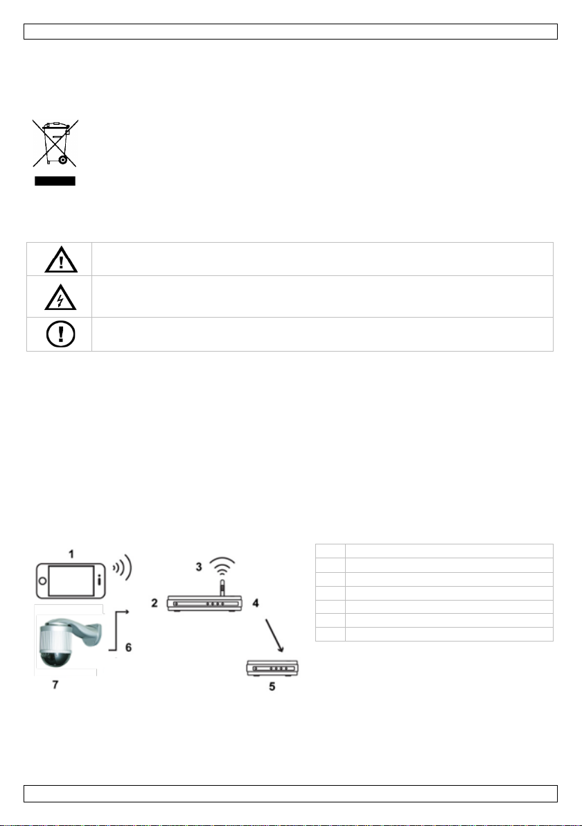
1
mobile device
2
LAN port
3
wireless router
4
WAN po rt
5
modem
6
8P 8C network ca ble
7
camera
QUICK INSTALLATION GUIDE
1. Introduction
To all residents of the European Union
Important environmental information about thi s product
Thank you for ch oosing Velleman! Please read the manual thoroughly before bringing this device into
servi ce. If the device was damaged in transi t, don't install or use i t and contact your dealer.
2. Safety Instructions
3. General Gui delines
Refer to the Velleman® Service and Quality Warranty on the last pages of this manual.
• Keep th is device away fr o m dust and extreme hea t.
• Protect thi s device fro m sho cks an d abu se. Avoid brute f orce when oper ating the device.
• Familiarise yourself with the functions o f the device before actually using it.
• All modi f ications of the devi ce are f orbidd en for safet y r ea sons.
• Only use the devi ce for i ts intended purpose. Using the device in an unauthorised way will void the
• Damage caused by di sregard of certai n guidelines in this manual is not covered by the warranty and
• DO NOT use this product to violate privacy laws or perform other illegal activities.
4. Overview
This symbol on th e device or the package indicates that disposal of th e device after its lifecycle
could harm the envi ronment. Do not dispose of the unit (or batteries) as unsorted municipal
waste; it sho uld be taken to a specialized company for recycling. This device should be
returned to y our distributor or to a local recycling service. Respect the local environmental
rules.
If in do u bt, co n t a c t y ou r loca l wa ste dispo sal au t h o rit ies.
Keep this device away from children and unauthorized users.
threaten in g electroshocks. Do not disassemble or open the housin g your self. H ave the
device repai r ed by qualified personnel.
There a r e no user-serviceable parts inside the device. R ef er to an authorized dealer for
service and/or spare part s.
warranty.
the dealer wi l l not accept respon sibil ity for any ensuing d ef ects or probl ems.
5. Installation: Hardware
Before installatio n, you need the following items:
• Bracket & mounting base (included)
• Mounting accessories (i ncluded):
o wall mounting screws
V. 01 – 14/02/2014 2 ©Velleman nv
Page 3
CAMIP18
o wall plugs
o cap
o M6 nylok screws
o sp irit leve l
o M4 screw
o mounting base screw
• Power drill
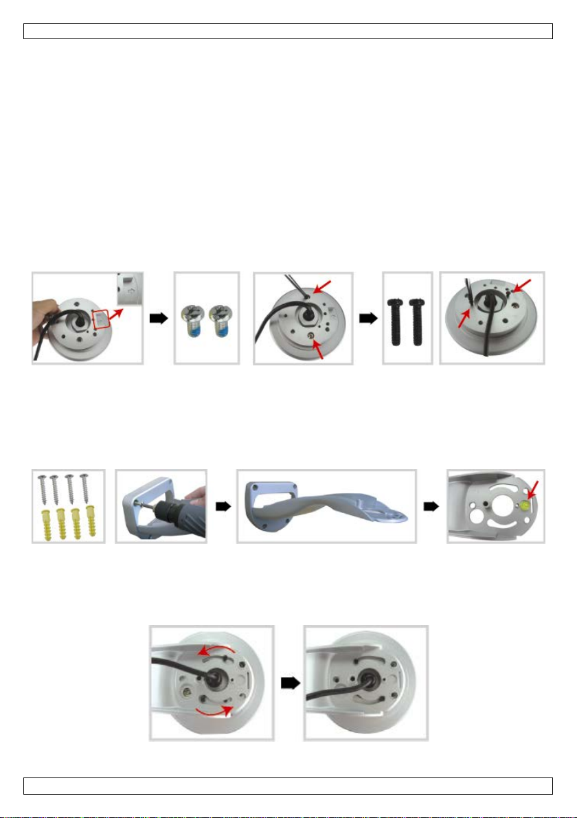
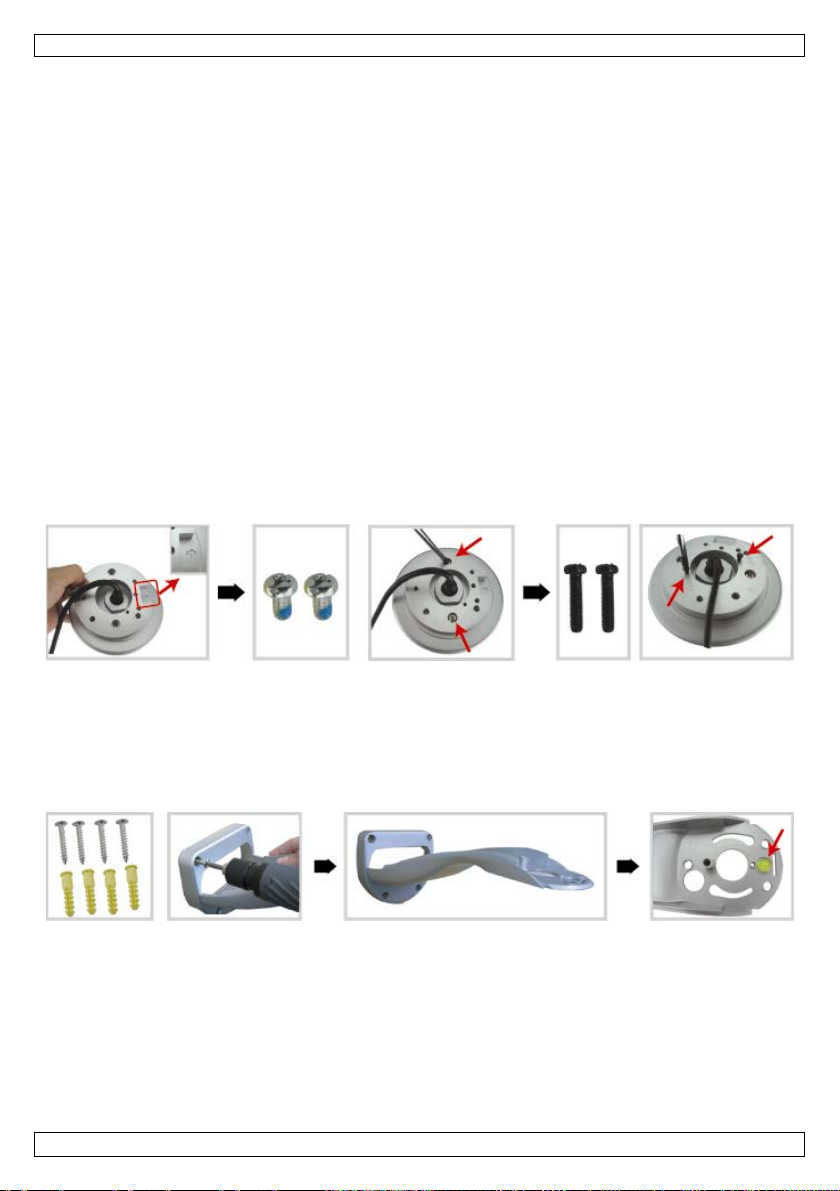
1. Attach the mountin g base to the speed dome camera.
• Put the cables (dependi n g on your configurati on, power suppl y and/or 8P8C network cables) through
the hol e of the ca mer a-mounting base.
• Ali gn the breach of the b ase t o the arr ow mark on th e speed dome camera , and use two M6 Nylok
screws t o a ttach the bas e to the speed dome camera .
• To make the bracket installation easier, fasten the two mounti ng base screws to the location as
shown below.
• Note: The screws are longer than the screw holes. Just fasten the screws until they’re fixed.
2. Attach the brac ket to the wall.
• The bracket is composed of t wo parts: the upper part and the bottom part. Remove the upper part
by loosening the screw on it. Use the four mounting screws and wall plugs to attach the bottom part
to the wall, as shown below.
• Use the spirit level supplied with the bracket package to check the surface is horizontal or not. If the
surface is horizontal, the bubble will remain in the centre circle of the spirit level.
3. Attach the speed dome camera to the bracket.
• Put the cables through the h ole of the bracket.
• Attach the camera to the bracket wi th the two mounting base screws going through, and rotate the
bracket as indicated b elow. The camera will be hooked on the bra cket.
• Slightl y secure the camera and the bracket with three M6 Nylok screws.
V. 01 – 14/02/2014 3 ©Velleman nv
Page 4
CAMIP18
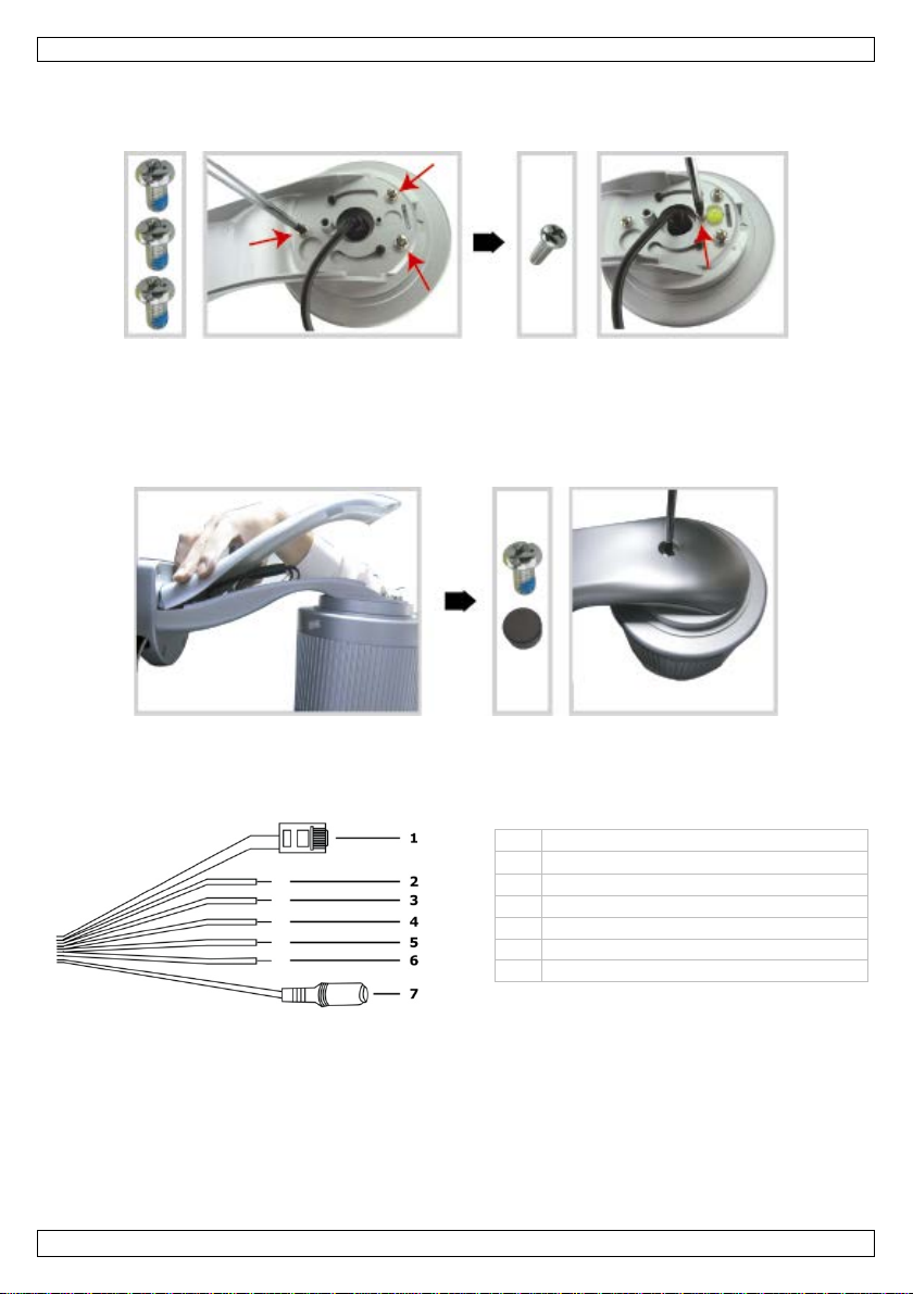
1
2
3
GND (brown)
4
RESET (red)
5
GND (black)
6
alarm out (pink)
7
power cable
• Use the spirit l evel to check the surface is horizontal or not, and adjust the tightness of the three M6
Nyl ok s crews.
• When you make sure the surface is hori zontal, use the M4 screw supplied with the bracket package
to fix the camera and the bracket tightly.
4. Connect the cables to you r r outer (and to a power ad ap ter if you are not using the Power over
Ether net feature). F or detail ed conn ection, please refer to section 6 below.
5. Put back the upper part of the bracket, and finish the installat ion.
• Pla ce the upp er part of the bracket back to the bottom par t of the bracket, a nd fasten the bracket
with the M6 Nylok screw loosened in STEP 1.
• Then use the cap supplied with the package to cover it and finish the installation.
6. Installation: Power Supply and PoE (Power over Ethernet)
Connection
Power Supply
8P 8C network c able
alarm in (yellow)
F or your c ame ra to work properly , you n eed to connect the ca mera cables as follow s:
1. Connect the net work cable [1] to your ne twork.
2. P lug the camera’s power cable [7] in a sui tab le power adapter (12 Vdc 1 A, for example PSSE1210,
not incl.) and connect it to a power socket.
V. 01 – 14/02/2014 4 ©Velleman nv
Page 5
CAMIP18
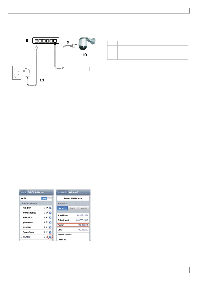
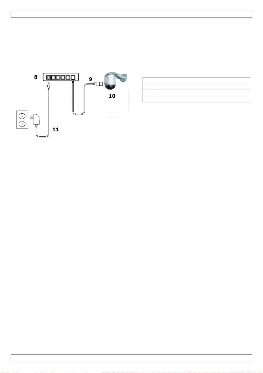
8
PoE r outer/hub
9
LAN cable
10
camera
11
power
3. Connect your m obile devi ce to the wireless router
PoE (Power over Ether net) Connection
The camera f eatures PoE (Power over Ethernet). If your router or hub supports PoE, you do not need to
connect the ca mera to a power socket. You can then conne ct the cam era as shown below:
1. U se a network cable [9] to connect your camera [10] to a P oE por t of y ou r rou t e r [8].
2. Make sure your r outer is conne cted to a power socket [11].
Note: If your router does not support PoE, you can use a PoE injector (not included) to use the PoE
feature.
7. Software Configuration
The installation method below describes the setup wi th an iPhone® with a D-Link® wireless router and
modem. The installation procedure is similar for iPad® or Andro id™ devices. Refer to the full manual on
the included CD-RO M for m ore informa tion.
Prerequisites
Before proceeding, check the following:
• We recommend that y ou use y our own ADSL or cable internet service for easy network configuration.
• Your camera is connected t o your wireless router with an 8P8C n et work cable, and it is powered on.
• EagleEyes-Li te or E agleEyes-Plus is installed on your device.
If not, download it from y our device’s app store.
Note: EagleEyes HD for iPad does not support network configuration. Please install EagleEyes-Lite or
EagleEyes Plus on your i Pad instead.
Preparing the Network Configuration
1. Connect your ca mera to your wireless router using an 8P8C n etwork cable (see “Overview” above).
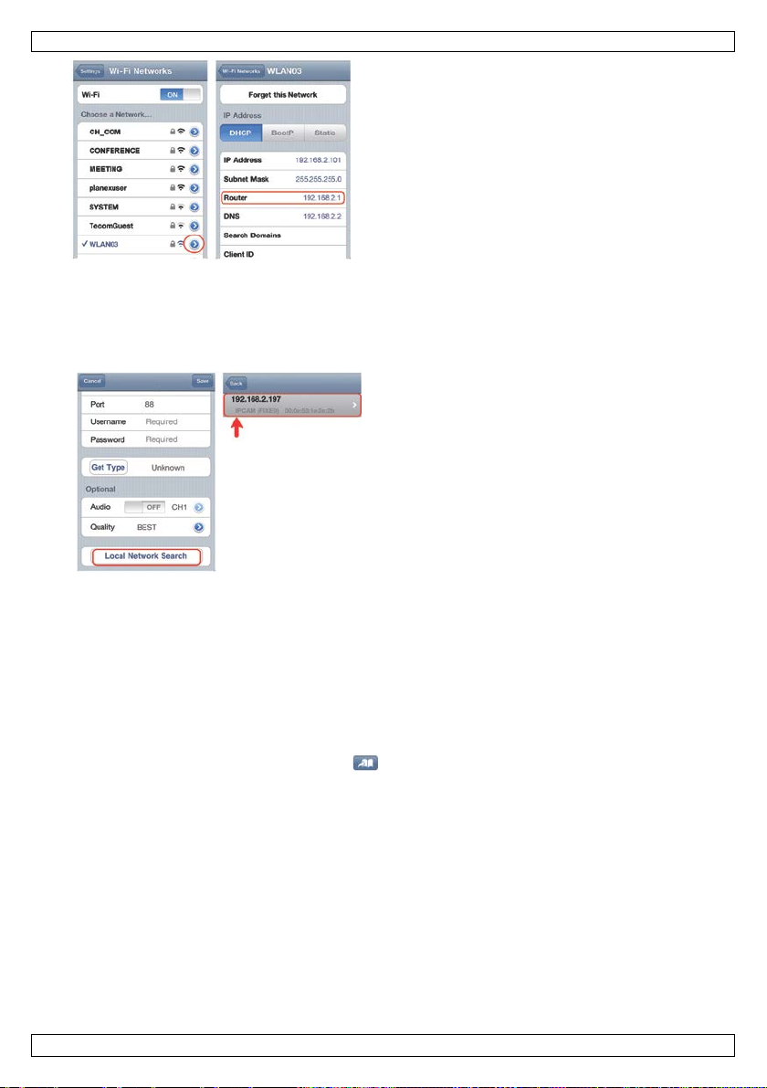
2. Write down the IP ad dress of your wireless router. You wi l l need it later. T o find the IP address,
proceed as follows:
that has the camera connected.
4. Go to Settings > WiFi.
5. P ress the “> ” butt on to s ee the details of the
selected wi rel ess network.
The IP address is visible next to “Router”.
(In the sample screen, the IP addr ess is
192.168.2.1)
Adding Your Camera to the EagleEyes App
1. Establish a wi reless connection between your mobi le device and the wi reless router that has the
camera connected.
2. Open the Eagl eEyes app and click the “+” button to add a new device.
V. 01 – 14/02/2014 5 ©Velleman nv
Page 6
CAMIP18
The device will show a list of devices on the
A B C
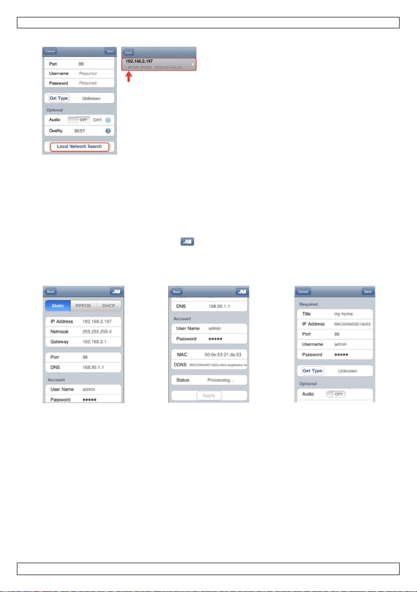
3. Select “L ocal Network Search” to search f or the camera.
networ k. The displayed IP add ress is the address
that your router assigned to your ca mera.
4. Select th e camera fro m the list. The settings page appears.
5. Change the p ort number of the camera as needed. The default port number is 88. If port number 88
is blocked, y ou can change it to any value between 1-9999 (for exa mple 8080).
6. Write down the I P address and the port number of the camera. You will need them l ater.
(In the sample screens b elow [A], the IP address is 192.168.2.197 and the port number is 88.)
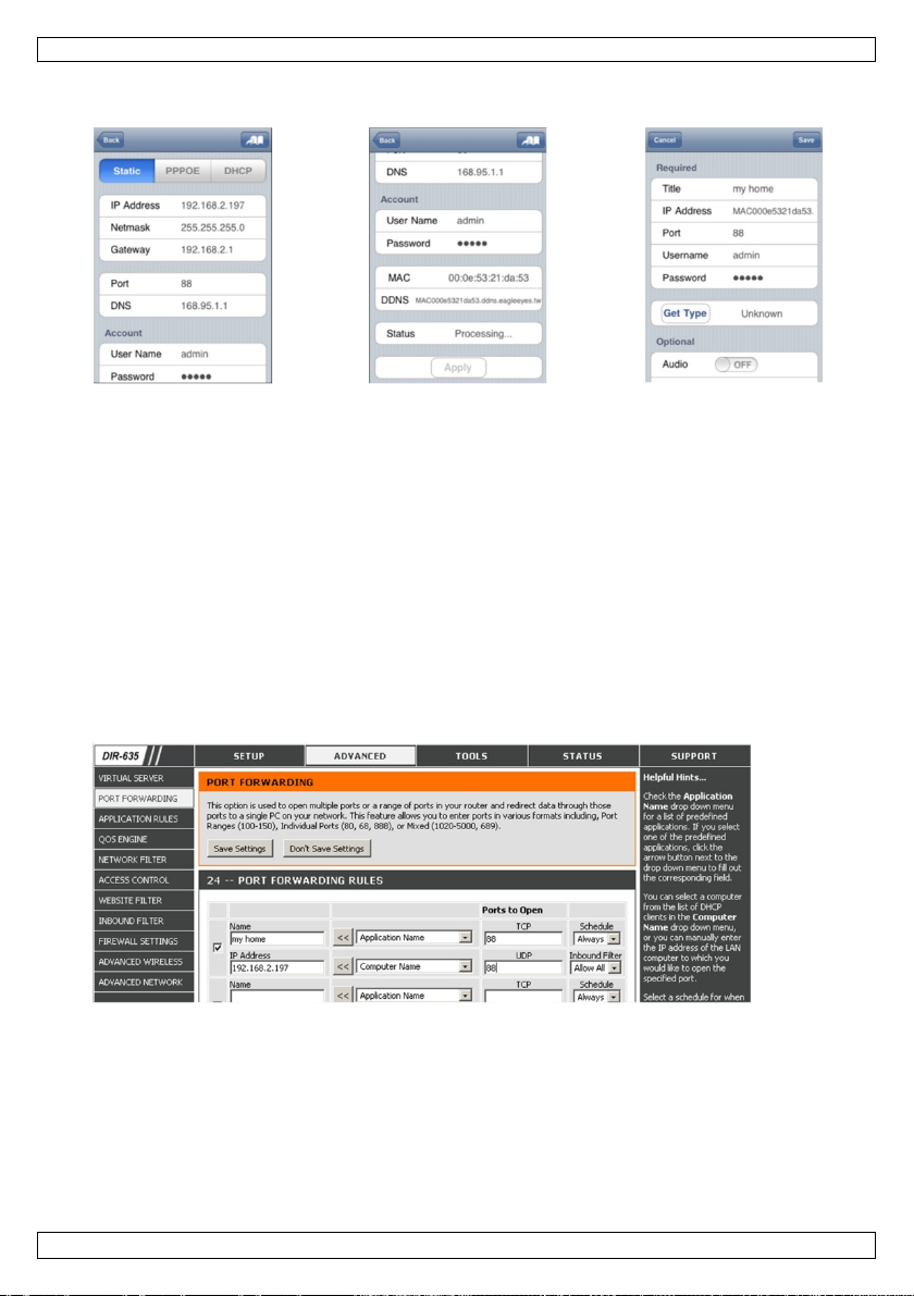
7. P ress “Apply” to confirm your setting s.
8. Wait un til “Status” [B] indicates “Done” or “Fail”.
o If the status shows “Done”, the device page appears again. Proceed with the next step.
o I f the status shows “ Fail”, pr ess t he button on the top right side of your device. In the
popup window, select “DDNS”. The device page appears again. Proceed with the next st ep.
9. I n “Title” [C], en ter a meaningful name for your camera connection and press “Sa ve” to confi rm.
Port Forwarding
At this moment, you can onl y access the camera when connect ed to your own wireless network, not
through the internet. This is because a home network is usually connected to the internet through a
router. On ly the router ’s external I P address (as signed to you by y our Internet S er vice Provid er ) can be
seen on the internet. Moreover, the router will also block a ccess to any device i n your home network,
includi ng your camera. To bypass this, most routers support a mechanism called port forw arding that
all ows ac cess from the internet to a device in the home network.
You can set up port f orwarding as f ollows:
1. Op en your web br o w ser on your mob ile device, and enter the IP address of your router you wrote
down in the address bar.
Your router c onfiguration page appears.
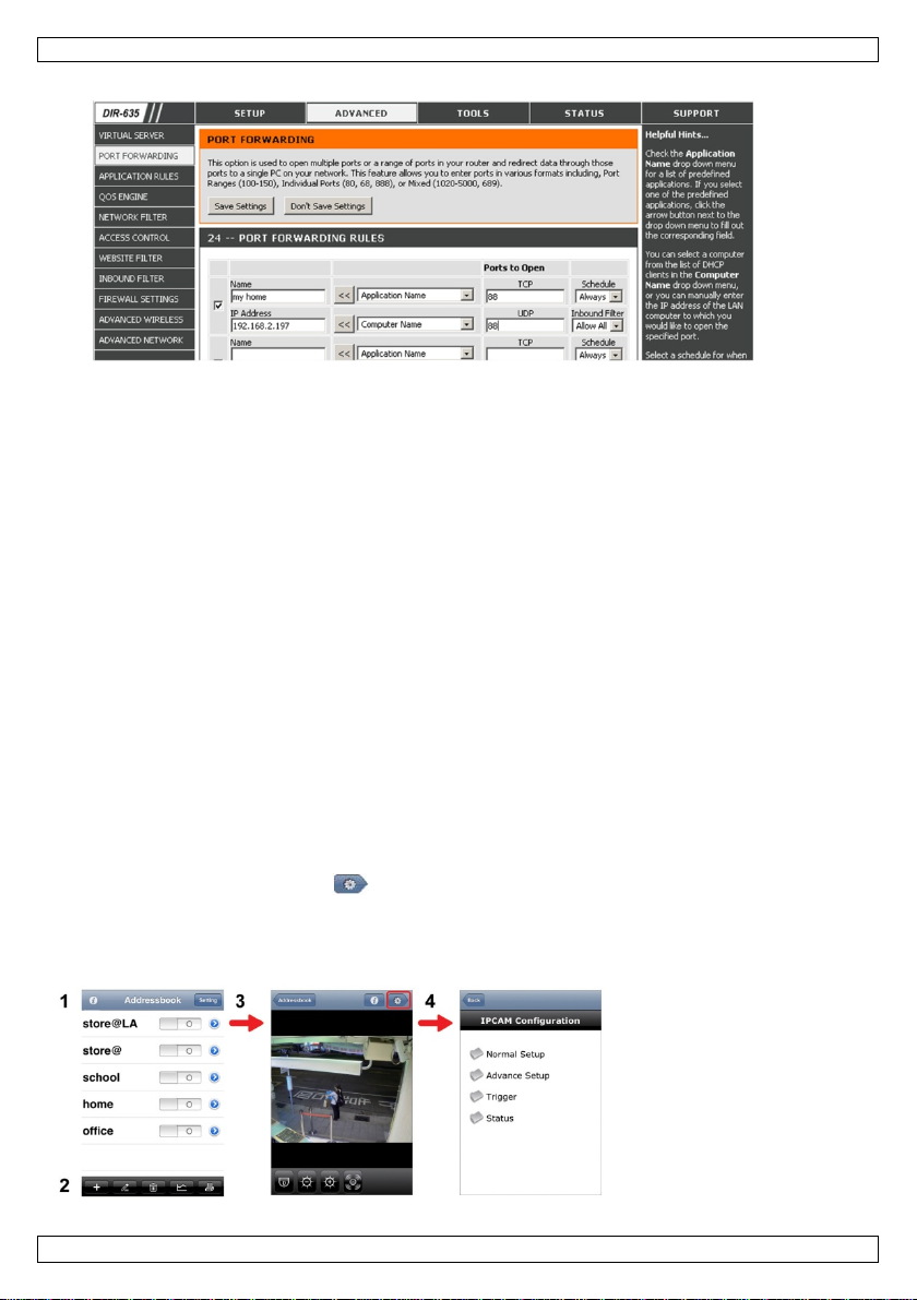
2. G o to the port forwarding (or virtual server) rule configuration page.
Note: The naming of port for wardi ng or virtual server may vary based on the brand of y our router.
Refer to the user manual of your specific router for more information.
The examp le below shows th e screen for a D-Link router: select the “Advanced” tab and then
V. 01 – 14/02/2014 6 ©Velleman nv
Page 7
CAMIP18
Address Book
Live View & Control
Configuration
choose “Port Forwarding”.
3. Enter the camer a IP address and port number that you noted down and enable this rul e. You can
now access your camera through the internet.
4. If your wireless router supports U PnP (Universal Plug and Play), make sure the function is enabled.
UPnP enhances communication b etween the router and wireless devices. If necessary, refer to the
manual of the router software.
Checking the Connection
When you have completed net work setup and port for warding, check your connecti on setup as follows:
1. On your mobile device, swi tch your network mode to 3G or connect to a different wir eless network
than the one that has your camera connected.
2. Start EagleEyes and select the camer a you just added to see if you can acc ess it.
o I f yes, your network connection works. Proceed with “Changing the Account User Name and
Password” below.
o If not, proceed with the fo llowing step.
3. Switch your network mode back t o the wi reless network that has your camera connected.
4. Start EagleEyes, and add a new connection with the IP address and port number that you set up in
“Adding Your Camera to the EagleEyes App”.
5. See if you can access the camera with this connecti on.
o If yes, return to “Port Forwarding” to set up p ort forwarding agai n .
o I f not, return to step 4 of “Adding Your Camera to the EagleEyes Ap p” and reconfigure the
connection.
Changing the Account User Name and Password in EagleEyes
To ensure the safety of your camera connection, modify the default user name and password as follows:
1. On your mobile device, access the camera i n EagleEyes.
2. Press the Configuration button .
3. Select Advance Setup > Account.
4. M odify the default user name (admin) and password (ad min) to the ones you prefer.
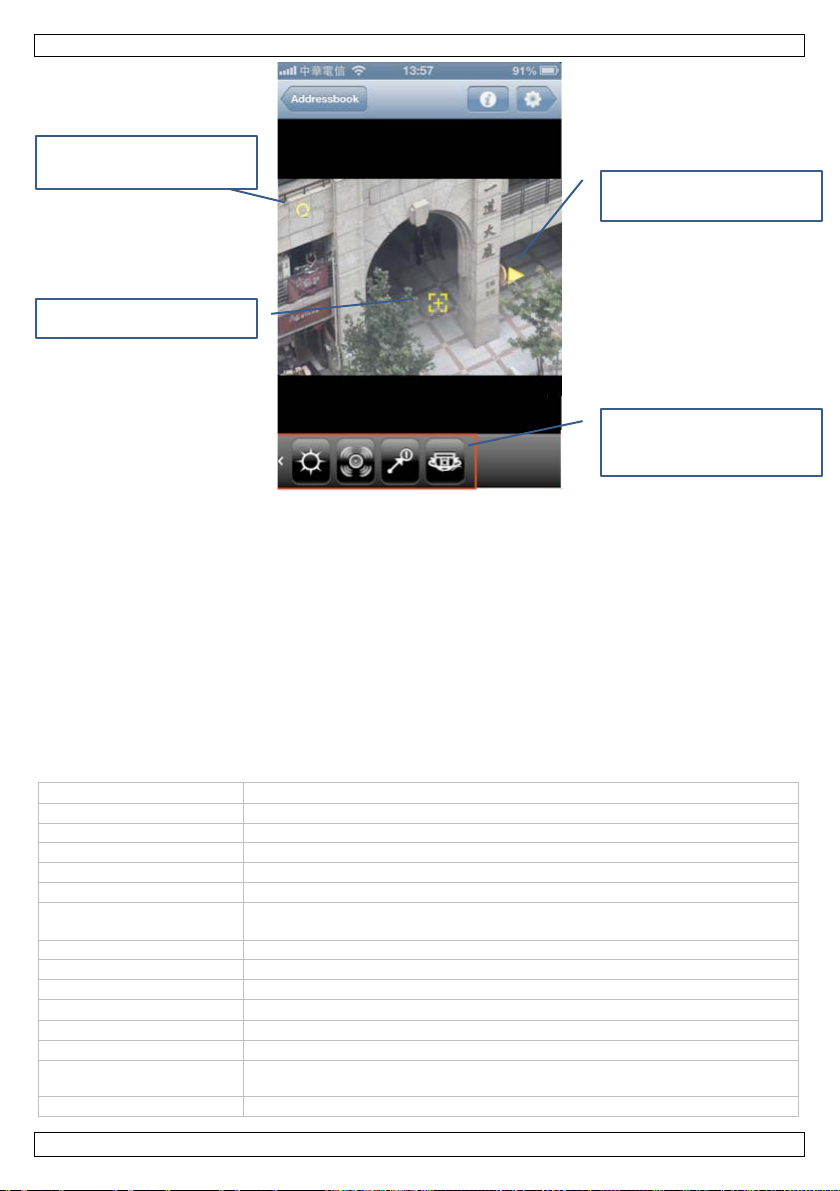
8. EagleEyes Operation
V. 01 – 14/02/2014 7 ©Velleman nv
Page 8

CAMIP18
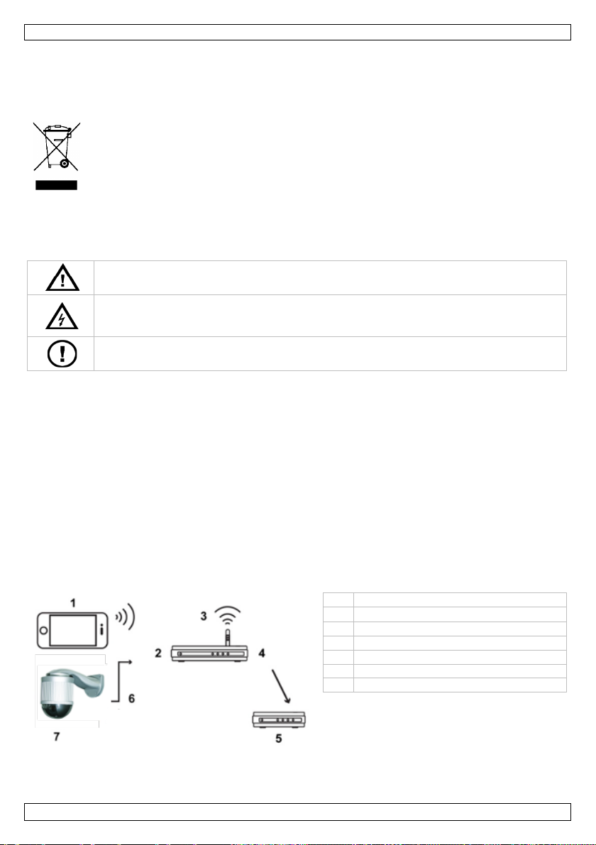
1
Info
Press for more in formation on how to use EagleEyes
2
Toolbar
Add, edit, and delete items from Address Book
3
Setting
Configure EagleEyes p arameters
Sel ect th e camera conne ction in Addr ess Bo ok to en ter Live View & Con trol.
4
pick-up el ement
Sony HR image sensor
image size
1/2.9"
number of pixels
2 megapixel
m in . illumin ation
0.1 lux / F2.0
white balance
ATW
WDR
yes
AGC
automatic
Sli de to pan the camera.
Use this button on the
Click this area to zoom.
When you start EagleEyes, Addres s B ook is displayed.
Configuration Press to enter the camera’s configuration pa g e.
Pan - tilt - zoom
The camera has a pan-tilt-zoom (PTZ) functi on. In EagleEyes, you can use the PTZ function as follows:
Double tap to zoo m to the
maximum.
control bar for pan, tilt and
zoom.
Touch screen gestures
You can also use
Swipe the screen up, down, left or right to pan and tilt the camera accordingl y.
Spread an area to zoom in.
Pinch an area to zoom out.
For detailed information, please check the full manual on the included CD-ROM.
ONVIF Certificat ion
The CAMIP18 IP camera is ONVIF certified: it is compatible with all major IP camera brands which are
ONVIF certified as well. For more informati on, p lease refer t o w w w.onvif.org.
9. Technical Spec ificat ions
V. 01 – 14/02/2014 8 ©Velleman nv
Page 9

CAMIP18
iris mode
AES
lens
f 6.0 mm - f 60.0 mm / F2. 0 - F2.8 (tele)
lens angle
53.5° - 6.1°
IR L E D s
-
network interface
Ethern e t 10/10 0BASE-T
PoE
IEEE 802.3af
multiple v ideo streaming
3 (H.264, MPEG4, MJPEG)
frame rate
30
image quality setting
1080P: 1920 x 1080
720P: 1280 x 720
VGA : 64 0 x 480
QVGA: 320 x 240
supported protocols
DDNS , PPPoE, DHCP, NTP, SNTP, TCP/IP, ICMP, SMTP, FTP, HTTP, RTP,
event notification
FTP / E-mail / SMS
mobile surveillance
smart ph ones: rem ote login via EagleEyes software on all major sm art
comput er: video viewer s oftware on Windows and Mac
web browser
Internet Explorer, Firefox, Google Chrome and Safari via Java, QuickTime
backup
remot e via smart phone
microphone
no
speaker
no
hardware requirements
Intel Core i3 or higher, or equivalent AMD
Windows® 7, Vista & XP, DirectX 9.0 or later
AGP graphi cs card, Direct Draw, 32 MB RAM
RAM 2 GB or hi gher
free network p ort
Internet Explorer 7.x or higher
operati ng temperature
-20 °C to 40 °C
power supply
12 Vdc 1 A (not incl.)
dimensions
206 x 147 mm (without bracke t )
weight
1950 g
IP rat ing
IP67
RTSP, RTCP, IPv4, Bonjour, UPnP, DNS, UDP, IGMP, QoS
pho ne platfo rms (iPad, iPhone and Android)
or VLC plug-in
memory st orage 20 MB (built-in)
external alarm I/O yes
Use this device with original accessories only. Velleman nv cannot be held responsible in the
event of damage or injury resulting from (incorrect) use of this device.
For more info concerning this product and the latest version of this manual, please visit our
website www.velleman.eu.
The information in this manual is subject to change without prior notice.
All r egistered trademark s and trade names are p roperties of their respective owners and ar e used only
for the clarification of the compatibility of our products with the products of the different manufacturers.
iPhone and iPad are trademarks of Apple I nc., registered i n the U.S. and other countries. D-Li nk, the DLink logo are trad emarks or registered trademark s of D-Link Corporation or its subsidiaries in the Uni ted
States and other countries. Android is a trademark of Googl e I nc.
© COPYRIGHT NOTICE
The copyright to this manual is owned by Velleman nv. All worldwide rights reserved. No part
of this man ual may b e copied, reproduced, tran slated or reduc ed to any electronic medium or otherwise
without the prior written consent of the c opyright holder.
V. 01 – 14/02/2014 9 ©Velleman nv
Page 10
CAMIP18
Elektrocutiegevaar bij het op enen van het t oestel. Raak geen kabels aan d ie on der
stro om staan, om dodelijke el ektr oschokken te ver mijden. Open d e behuizing niet zelf . Laat
Er zijn geen door de gebruiker ver vangbare onderdelen in dit toestel. Voor ond erh oud en/of
1
2
3
draadloze router
4
WAN-poort
5
modem
6
8P8C-netwerkkabel
7
KORTE HANDLE I D I NG
1. Inleiding
Aan alle i ngezetenen van de Europese Unie
Belangrijke milieu-informatie betreffende dit product
verwijdering.
Dank u voor uw aankoop! Lees deze handleiding grondig voor u het toestel in gebrui k neemt. Werd het
toestel beschadi g d tijden s h et transport, in stalleer het dan ni et en raadpleeg uw dealer.
2. Veiligheidsinstructies
3. Algemene r ichtlijnen
Raadpleeg de Vell eman® service- en kwaliteitsgarantie achteraan deze handleiding.
• Bescherm dit toestel teg en stof en extreme temp eraturen.
• Bescherm tegen schok ken. Ver mijd brute kra ch t tijdens de bed iening.
• Leer eerst d e functies van het toestel kennen voor u het gaat gebruiken.
• Om veiligheidsredenen mag u geen wijzigingen aanbrengen.
• Gebruik het toestel enkel waarvo or het gemaakt i s. De garantie vervalt automatisch bij ongeoorloof d
• De gar a ntie g el d t niet voor schade do or h et negeren van bepaalde richtli j nen in deze handleiding en
• Installeer en gebruik deze camera NIET voor illegale praktijken en respecteer ieders
4. Omschrijving
Dit symbool op het toestel of d e verpakking geeft aan d a t, a ls het na zijn levenscyclus wordt
weggewor pen, d it toestel schade kan toebrengen aan het mili eu. Gooi dit toestel (en eventuele
batterijen) niet bij het gewone huishoudelijke af val; het moet bij een gespeciali seer d bedri j f
terechtkomen voor recyclage. U moet dit toestel n aa r uw verd eler of naar e en lokaal
recycla g epunt b rengen. Resp ecteer de pl aatselijke milieuwetgevi ng.
Hebt u vr agen, con tacteer dan de plaatselijke autoriteiten betreffende de
Houd dit toe stel buiten het bereik van kinderen en onbevoegden.
het on d erhoud van h et toestel over aan een geschoolde va kman.
reserveonderdelen, conta cteer uw dealer.
gebruik.
uw deal er zal de verantwoordeli j kh ei d afwijzen voor defec ten of pr oblemen di e hier rechtstreeks
verband mee houden.
privacy.
draagbaar toestel
LAN-poort
camera
V. 01 – 14/02/2014 10 ©Velleman nv
Page 11
CAMIP18
5. Installatie: Hardware
Voor de installatie hebt u de volgende items nodig:
• Beugel & montageplaat (meegeleverd)
• Montagetoebehoren (meegeleverd):
o wandmontageschroeven
o muurpluggen
o dop
o M6 Nylok-schroeven
o waterpas
o M4-schroef
o m on ta g e s c h r oe f v oor voe t
• Klopboormachine
1. Bevestig de montag evoet aan de ko ep elcamera.
• Voer de kabels (afhankelijk van d e configuratie, voed ing en/of 8P8 C-netwerkkabels) door het gat in
de montagevoet van de camera.
• Li j n de uitsparing op de m ontagevoet van de camera met h et pij lteken op de camera uit, en gebruik
twee kl eine M6-Nylok-schroeven om de montagevoet aan d e camera te bevestigen.
• Om de installatie van de beugel gemakkelijker te maken, bevestigt u d e twee sch roeven van de
montagevoet al s vol g t:
• Opmerking: De schroeven zijn langer dan de schroefga ten. Draai de schroeven va st tot ze ste vig
vastzitten.
2. Bevestig de beugel aan de muur .
• De beu gel bestaat uit twee delen: het b ovenste en het onderste g edeelte. V erwijder het bovenste
gedeelte door de schr oef erop los te draaien . Gebruik de vier montages ch roeven en pl uggen om het
onders te g edeelte aa n de mu ur te bevestigen ( zi e af b.).
• Gebruik het waterpas (meegelev.) o m te controleren of het opp ervlak horizontaal is. Al s het
oppervlak horizontaal is, zal de luchtbel in de middencirke l van het waterpas blijven.
3. Bevestig de koepelcamera aan d e beugel.
• Voer de kabels door het gat in de b eugel.
• Bevestig de camera met de twee schroeven van de montag evoet aan de beugel en draai de camera
zoals hieronder aan gegeven. De camera w ordt op de beugel g ehaakt.
V. 01 – 14/02/2014 11 ©Velleman nv
Page 12

CAMIP18
1
2
alarmingang (gee l)
3
GND (bruin)
4
RESET (rood)
5
GND (zwart)
6
alar muitgang (roze)
7
• Schroef de camera en d e b eugel met de drie M6 Nylok-schroeven voorzichtig vast.
• Gebrui k het waterpas om te controleren of het oppervl ak horizontaal is en pas de spanning van de
drie M6 Nylok-schroeven aan.
• Wanneer het oppervlak horizontaal i s, gebruik dan de M4-sch roef ( meegelev.) om de camera en de
beugel goed vast te ze tten.
4. Sluit de kabels aan op uw router (en a a n een netadapt er als u de Power over Ethernet-functie niet
wilt gebruiken). Voor meer informatie, zie hoofdstuk 6 hieronder.
5. P laats het bovenste g edeelte van de beugel terug en vo ltooi de installatie.
• Plaa ts h et bovens te gedeelte van de beugel ter ug op het onder ste g edeelte van de beugel en
bevestig de beug el met de M6 Nylok-schroef die u hebt losgedraaid in STAP 1.
• Gebruik vervolgens d e d op (meegelev.) om he t sch roefgat af te d ekken en de installatie te voltooien.
6. Ins tallatie: Voed ing en Po E -aansluitin g (Power over Ethernet)
Voeding
8P8C-netwerkkabel
voedingskabel
V. 01 – 14/02/2014 12 ©Velleman nv
Page 13
CAMIP18
8
PoE-router/hub
9
LAN-kabel
10
camera
11
voeding
Voor een correcte werking van d e cam er a, sluit u de camerakabel s aan als volgt:
1. Verbind de netwerkkabel [1] met uw netwerk.
2. Slui t de voedi n gskabel van de camera [7] aan op een gesch ikte netadapter (12 Vdc 1 A, bijv.
PSSE1210, niet meegelev.) en steek in een stopc ontact.
PoE-aansluiting (Power over Ethernet)
De camera is uitgerust met P ower over Ethernet. Indien uw router of hub PoE ondersteunt, dan moet u
de camera niet aansluiten op het lichtnet. Sluit de camera aan als volgt:
1. Geb r uik een netwerkkabel [9] om uw camera [10] aan te sluiten op een PoE-poort van uw
router [8].
2. Zorg ervoor dat uw router aangesloten is op het lichtnet [11].
Opmerking: Indien uw router P oE niet ondersteunt, gebruik dan een PoE-inject or (n iet meegeleverd) om
PoE te geb ruiken.
7. Softwareconfiguratie
De installatiemethode h ieronder beschr ijft de configuratie voor iPhon e® met een draadlo ze D-Link®
router en modem. De installatiep rocedure is gelijkaardig voor iPad® of Androi d™ toestellen. Raadpleeg
de uitgebreide h andlei ding op de meegeleverde cd-rom.
Vereisten
Al vorens ver der te gaan:
• We raden u aan om uw eigen A DSL of internetkab eldien st te g ebruiken voor een eenvoudige
netwerkconfiguratie.
• Verifieer of uw camera verb onden is met uw draa d loze router via een 8P8C-netwerkkabel en
ingescha keld is.
• Verifieer of EagleEyes-Lite of EagleEyes-Plus geïnstalleerd is op uw toestel.
Is dit niet het geval, downl oad de app via de app store van uw toestel.
Opmerking: Ea g leEyes HD voor i P ad ondersteu nt geen netwerkconfiguratie. Installeer EagleEyesLite of EagleEyes Plus op uw iPad als alternatief.
De netwerkconfiguratie voorbereiden
1. Verbind uw camera met uw d r a ad loze router via een 8P8C-netwerkkabel (zie “Overzicht”
hierboven).
2. Noteer het IP-adres van uw draadloze router. U zal het later nog nodi g hebben. Om het IP-adres te
vinden, gaat u als volgt te werk:
V. 01 – 14/02/2014 13 ©Velleman nv
Page 14
CAMIP18
Het toe stel zal een lijst ton en met toestellen die
3. Verbind uw draagbaar toestel met de draadloze
router waarmee de camera verbonden is.
4. Ga n aar Settings > WiFi.
5. Druk op de “>” toets om meer details van h et
gesel ecteerde draadloze n etwerk te zien .
Het IP-adres wordt naast “R outer” weergeg even .
(In het voor beeld scherm is het IP-adres
192.168.2.1)
Uw camera toevoegen aan de EagleEyes app
1. Maak een draadloze verbi nding tussen uw draagbaar toestel en de draadl oze router waarmee de
camera ver bonden i s.
2. Op en de Eagl eEyes app en klik op “+” om een nieuw toes tel toe te voegen.
3. Selecteer “Local Netw ork Search” om te zo eken naar de camera.
verbonden zi jn met het netwerk. Het IP-adres dat
verschijnt, is het adres dat door uw router werd
toegeken d aan uw camer a.
4. Selecteer de camera in de li j st. De configuratiepagi na verschijnt.
5. Verander het poortnummer van de camera indien nodig. Het standaard poortnummer is 88. Als
poortnummer 88 gebl okkeer d is, kunt u dit aanpassen naar een will ekeurige waard e tussen 1-9999
(bijvoorbeeld 8080).
6. Noteer het IP-adres en het poortnummer van de camera. U zal d eze nog nodig hebben.
(In de voor b eelden hieronder [A], is het IP-adres 192.168.2.197 en he t poortnummer 88.)
7. D ru k op “Apply” om u w instellingen te bevestigen.
8. Wacht totdat “Status” [B] “Done” of “Fail” weergeeft.
o Al s d e status “D one” weergeeft, verschi j nt de pagina van het toestel opnieuw. Ga verd er met de
volgende stap.
o Geeft d e status “Fail” weer , druk op de knop rechtsboven op uw toestel. In het pop-
upven ster selecteert u “D DNS”. De pag ina van het toestel verschijnt opnieuw. Ga verder met de
volgende stap.
9. Geef in “Title” [C] een herkenbare naa m in voor de aansluiting van uw camera en druk op “Save”
om te bevestigen.
V. 01 – 14/02/2014 14 ©Velleman nv
Page 15
CAMIP18
A B C
Port forwarding
Momenteel hebt u enkel toegang t ot de c a mera indi en deze v erbon d en is met uw eigen draadloos
netwerk, niet vi a het i nternet. Dit komt o mda t een stan daard th uisnetwerk meestal verb ond en is met het
internet via een router. E nkel het externe I P-adres van de router (toegewezen door uw internetprovider)
is zich tbaar op het internet. Bo vendi en blokkeert de router ook alle toegan g tot de t o estellen in u w
thuisnetwerk, ook u w camera. Om dit te omzeilen, gebr uiken de meeste rout ers de functie port
forwarding waardoor er internettoeg ang is naar een toestel in het thuisnetwerk.
Om de functie port forwarding in te stellen, gaat u als volgt te werk:
1. Open de webbrowser op u w draagbaar toe stel en tik het IP-adres van uw router dat u hebt
genot eerd i n de adresbalk.
De configuratiepagina van uw rout er verschijnt.
2. Ga naar de configuratiepagina met de instellingen van de functie port forwardi ng (of vi rtuele
server).
Opmerking: Het d ef iniëren van de port for w a r ding of virtuele server kan variëren afhankelijk van
het type rou ter. Ra ad pleeg de geb r uikershan dleiding van u w router voor meer i nformatie.
Het vo orbeeld hierond er to ont h et scherm v oor een D-Li nk router: sel ecteer “Advanced ” en
vervol gens “Port Forwarding”.
3. Geef het I P-adres van de camera en het poortnummer in die u noteerde en activeer de ze i nstelling.
U kunt nu de camera bereiken via internet.
4. Als uw draadloze router UPnP ondersteunt (Universal Plug and Pl ay), zorg er dan v oor dat deze
fun ctie actief is. UPnP versterkt de communicatie tu ssen de r outer en draadlo ze to estellen.
Raadpleeg de handl eiding van de routersoftware indien nodig.
De verbinding controleren
Wanneer de net werkconfig uratie en poortd oorschakeli ng voltooid zijn, control eer t u de set-up van uw
verbinding als volgt:
1. V ia uw draagbaar toest el stelt u uw netwerkmodus in naar 3G of maakt u verbinding met een ander
draad loos n etwer k d a n da t w a armee uw camera verbonden is.
V. 01 – 14/02/2014 15 ©Velleman nv
Page 16

CAMIP18
1
2
Werkbalk
Toev oegen, ver a nderen en items wissen uit Address B oo k
3
Instelling
EagleEyes parameter s instellen
Sel ecteer de verbinding met de camer a in Adress Book om naar Live View & C ontrol te gaan.
4
Configuratie
Dru k om naar de configuratiep ag ina van de camera te gaan.
2. Start Eag leEyes en selecteer de camera d ie u zopas hebt toegevoegd om te zien of u t oegan g hebt.
o Hebt u toegang, dan is uw netwerkverbinding OK. Ga door naar “Gebruiksnaam en
wacht woor d w ijz igen in EagleE y e s ”.
o Is dit niet het geval, ga dan ver der met de volgen d e stap .
3. Verand er de netwerkmodu s van het draadloze netwerk waarmee uw cam era verbond en is.
4. Start Eag leEyes en voeg een nieu we verb inding toe met h et IP-adres en poortnummer die u hebt
ingesteld onder “Uw camera toevoegen aan de Eag leEyes app”.
5. Controleer of u toegang hebt tot de ca mera met de ze ver bindin g .
o Hebt u toegang, ga verder met “Port forwarding” om de port forwarding opnieuw in te stellen .
o Is dit niet het geval, keer terug naar stap 4 “Uw camera toevo egen aan de EagleEyes app”
en pas de verbinding aan.
Gebruiksnaam en wachtwoord wijzigen in EagleEyes
Om de verbindin g met u w ca mera veilig te stellen, ver ander de standaar d gebrui kersnaam en
wachtwoord als volgt:
1. V ia uw draagbaar toest el gaat u naar de camera in EagleE yes.
2. D ruk op de configuratieknop .
3. Selecteer A dvance Setup > A ccoun t.
4. Verander de standaard gebruikersnaam (admin) en het wachtwoord (admin) naar keuze.
8. Werk en met Eag leEyes
Adresboek Live View & Control Configuratie
Wanneer u EagleE yes op start, verschijnt A d ress Bo o k.
Info Dru k vo or meer informatie ov er het gebruik van EagleEyes
Pan - tilt - zoom
De camera is uitgerust met een pan-tilt-zoom (PTZ)-functie. I n EagleEyes kunt u de PTZ-functie
gebruiken als vo lgt:
V. 01 – 14/02/2014 16 ©Velleman nv
Page 17
CAMIP18
opneemelement
Sony HR image sensor
beeldgrootte
1/2,9"
aantal pixels
2 megapixel
min. verlicht ing
0.1 lux / F2.0
witbalans
ATW
WDR
ja
automatische versterking
automatisch
irissturing
AES
lens
f 6.0 mm - f 60.0 mm / F2. 0 - F2.8 (tele)
netwerkinterface
Ethern e t 10/10 0BASE-T
PoE
IEEE 802.3af
meervoudige
3 (H.264, MPEG4, MJPEG)
beel den per second e
30
Veeg m et uw vinger om de
Gebruik deze knop om d e
Tik tweemaal om maximaal
Klik op dit gebied om in te
in te zoomen.
camera te draaien.
PTZ-functie aan te sturen.
Touchscreen-bewegingen
U kunt ook
Uw wijsvinger op het s ch erm plaatsen en naar omhoog, omla ag , links of rechts veg en om de cam era
horizontaal of verticaal te bewegen.
Uw duim en wijsvinger op het scherm spreiden om in te zoomen.
Uw duim en wijsvinger op het scherm sa menknijpen om uit te zoomen.
Raadp leeg de uitgeb reide han dleiding op de m eeg eleverde cd -rom voor meer informati e.
ONVIF-norm
De CAMIP18 IP-ca mera is ONVIF-gecertificeerd: de camera is compatibel met de voornaamste IPcameramerken die o ok ON V IF-gecertificeerd zijn. Zie www.onvif.org voor meer informatie.
9. Technische specificaties
(AGC)
lenshoek 53.5° - 6.1°
IR-leds -
videostreaming
V. 01 – 14/02/2014 17 ©Velleman nv
Page 18

CAMIP18
regeling beeldkwaliteit
1080P: 1920 x 1080
720P: 1280 x 720
VGA : 64 0 x 480
QVGA: 320 x 240
ondersteunde protocols
DDNS , PPPoE, DHCP, N T P, S N TP, TCP/IP, ICMP, SMTP, FTP, HT T P, RTP,
waarschuwingsbericht
FTP / E-mail / SMS
bewaking op afstand
smartphones: login op afstand via Eagl eEyes software op de voornaamste
comput er: video vi ewer-software op Windows en Mac
webbrowser
Internet Explorer, Firefox, Google Chrome en Safari via Java, QuickTime of
back-up
op afstand via smar tphone
geheugen
20 MB (ingebou wd)
externe alarm I/O
ja
luidspreker
nee
systeemvereisten
Intel Core i3 of hoger, of AMD (gelijkwaardig)
Windows® 7, Vista & XP, D irectX 9.0 of hoger
AGP grafi sche kaart, Direct Draw, RAM 32 MB
RA M 2 MB of hoger
werktemperatuur
-20 °C tot 40 °C
voeding
12 Vdc 1 A (niet meegel ev. )
afmetingen
206 x 147 mm (zon der beuge l)
gewicht
1950 g
IP-norm
IP67
RTSP, RTCP, IPv4, Bonjour, UPnP, DNS, UDP, IGMP, QoS
smartphones (i Pad, iPhone en Android)
VLC plug-in
microfoon nee
vrije netwerkaansluit ing
Internet Explorer 7.x of hoger
Gebruik dit toestel enkel met or iginele accesso ires. Velleman nv i s niet aansprakelijk voor
schade of kwetsuren bij (verkeerd) gebruik van dit toestel.
Voor meer info rmatie over dit product en de laatste versie van deze handleiding , zi e
www.velleman.eu.
De informatie in deze handleiding kan te allen tijde worden gewi j zi gd zonder vo orafg a ande
kennisgeving.
All e g eregistreer d e handelsmerken en handel sn a men zijn eigendom van hun respectieve bezitters, en
zijn en kel gebruikt als voor b eeld van de c o mpa tibiliteit tussen onze pr oducten en de p roducten van de
verschillende fabrikanten.
iPhone en iPad zijn handelsmerken van Apple Inc., geregistreerd in de VS en andere lande n. D-Link, de
D-Link logo's, zijn hand el smerken of ger eg istreerde handelsmerken van de D-Link Corporation of haa r
dochteron derneming en in de Verenigd e S taten en andere landen. Android is een handelsmerk van Google
Inc.
© AUTEURSRECHT
Velleman nv heeft het auteursrecht vo or deze handleiding. Alle werel dwijde rechten
voorbehouden. Het is niet toeges ta an om deze hand leidin g of ged eelten ervan over te nemen, te
kopiëren, te vertalen, te bewerk en en op te slaan op een elektronisch medium zonder v o orafgaande
schriftelijke toeste mming van de r echthebbende.
V. 01 – 14/02/2014 18 ©Velleman nv
Page 19

CAMIP18
risque d’électro cut ion lors de l’ouverture du boîtier. Toucher un câble sous tension peut
1
dispositif mobile
2
port LAN
3
routeur sans fil
4
port WAN
5
modem
6
câbl e de réseau 8P8C
7
caméra
GUIDE D'INSTALLATION RAPIDE
1. Introduction
Aux résidents de l'Union européenne
Informations environnementales importantes concernant ce produit
En cas de doute, contacter les autorités lo cales pour éliminat ion.
Nous vous remercions de votre achat ! Lire le pr ésen t mode d 'emploi attentivement avant la mise en
servi ce d e l'appareil. Si l'appareil a été endommagé pend ant le transport, ne pa s installer et consulter
votre reven d eur.
2. Consignes de sécurité
3. Directives générales
Se référ er à la garanti e de service et d e qualité Vel leman® en fin de ce mode d'emploi.
• Protéger cet appareil contre la poussière et la chaleur extr ême.
• Prot éger l ’appareil des chocs. Traiter l'appareil avec circonspection pendant l’opérati on.
• Se familiariser avec le fonctionnement de l'appareil avant de l'utiliser.
• Il est interdit de modifier l'appareil pour des raisons de sécurité.
• N’utiliser l'appareil qu’à sa fonction prévue. Un usage impropre annule d'office la garantie.
• Les dommag e s occasionnés par des modifications à l'appar eil par le client, ne tombent pas s ous la
• Installer et utiliser la camér a en respectan t la législation et la vie pri vée des tiers.
4. Description
Ce symbole sur l'appareil ou l'emballage indique que l'élimination d'un appareil en fin de vie
peut polluer l'environnement. Ne pa s j eter un appareil électri que ou électronique (et des piles
éventuelles) parmi les déchets municipaux non su j ets au tri sélectif; une déchetter ie traitera
l'appareil en question. Renvoyer cet ap p a r eil à votre f our nisseu r ou à u n service de recyclage
local . Il convient de respecter la réglementation locale r elative à la pr otection de
l'environnement.
Garder l 'appareil hors de l a portée des enfan ts et des personnes n on au tor isées.
causer des électrochoc s mortels. Ne jamais démonter ou ouvrir le boîtier soi-même. Confier
la r ép ar ation de l'appareil à du personnel qualifié.
Il n’y a au cune pièce rép arable par l ’utilisateur. Com man d er des pièce s d e rechang e
éventuelles chez v otre revendeur.
garantie et votre revendeur déclinera toute responsabilité pour les p roblèmes et l es d éf a uts qui en
résultent.
5. Installation : Matériel
Avant l'install ation, vous avez besoin des éléments suivants :
• Support & base de montage (incl . )
V. 01 – 14/02/2014 19 ©Velleman nv
Page 20

CAMIP18
• Acce ssoires de montage (i ncl.) :
o vis de montage mural
o chevilles murales
o bouchon
o vis N ylok M6
o niveau à bulle
o vis M4
o vis pour base de montage
• Perceuse
1. Fixer la base de montage à la caméra dôme.
• Passer les câbles (selon la configuration, alimentatio n et/o u câbles de réseau 8P8C) par le trou dans
la base de montage de la caméra.
• Ali g ner la fente dans la b ase de montage de la caméra avec la marque fléch ée sur la caméra dôme,
et utiliser deux vis N ylok M 6 pou r fi xer la base de montage à la caméra dôme.
• Pour faciliter l'installation, fixer les deux vis de la base de montage comme illustré ci-dessous.
• Remarque : Les vis sont plus longues que les trous de vis. Serrer l es vis jusqu'à ce qu'elles soie nt
bi en fixées.
2. Fixer le support au mur.
• Le support est c omposé de deux par ties : la partie supérieure et la partie inféri eure. Enlever la partie
supérieure en desser rant la vi s du dessus. Utiliser les qu atre vis de montage et les chevi lles murales
pour fixer la part ie inférieure au mur (voir ill.).
• Utiliser le niveau à bulle (inc l.) pour vérifier que la surface est horizontale ou pas. S i la surface est
horizontale, la bulle restera dans le cercle central du niveau à b ulle.
3. Fixer la caméra dô me au su p por t.
• Pass er les câbles par le trou dans le support.
• Fixer la caméra au suppor t avec les deux vis de la base de montage, et fai r e tourner la caméra (voir
ill.). La caméra sera accroch ée au support.
V. 01 – 14/02/2014 20 ©Velleman nv
Page 21

CAMIP18
1
câbl e de réseau 8P8C
2
entrée d 'alarme (jaune)
3
GND (brun)
4
RESET (rouge)
5
GND (noir)
6
7
câble d’alimentation
• Fixer légèrement l a camér a et le supp ort avec trois vi s Nylok M6.
• Utiliser le niveau à bulle pour vérifier que la sur f a ce est h orizontale ou pas, et ajuster l e serrage d es
trois vis Nyl ok M6.
• Lorsque la surface est horizontale, utiliser la vis M4 (incl.) pour fixer la caméra et le support
fermement.
4. Connecter les câbles au routeur (et à l'adaptateur réseau si vous n'utilisez pas la fonction Power
over Ethernet). Pour plus d'informations, voir chapitre 6.
5. Remettre la par tie supérieure du su p port, et terminer l'i nstalla tion.
• Remettr e la parti e supérieure du support sur la partie inférieure du su p port, et fixer le supp ort avec
la vi s Nyl ok M6 d esserrée d ans ETA P E 1.
• Ensuite, utiliser le bouchon (incl.) pour recouvrir le tro u de vis et terminer l'installation.
6. Inst a llation: Conne xi on d'a l ime n tat ion e t PoE (Powe r ove r
Ethernet)
Alimentation
sortie d'alarme (rose)
Pour garantir un fonctionnement correct de la caméra, connecter les câbles de la caméra comme suit :
1. Conn ecter le câble réseau [1] à votre réseau.
2. Raccorder le câble d'alimentation [7] à l'adaptateur secteur (12 Vcc 1 A, p.ex. PSSE1210, non incl.)
et brancher sur une prise.
V. 01 – 14/02/2014 21 ©Velleman nv
Page 22

CAMIP18
8
routeur/hub PoE
9
10
11
alimentatio n
3. Connecter v otre di sp ositif mobile au routeur sans
Connexion PoE (Power over Ethernet)
La camér a est dotée de la f onction PoE (Po w er over Ethernet). Si vo tr e routeur ou hub supporte PoE, il
ne faut pas connecter la caméra au réseau électrique. Connecter la camér a comme suit :
câble LAN
caméra
1. U tiliser un câble réseau [9] pour connecter votre ca méra [10] au port PoE de votre routeur [8].
2. S'assurer q ue votre routeur est connecté au rés eau électrique [11].
Remarque : Si votre routeur ne supporte pas PoE, il est possible d'utiliser un injecteur PoE (non incl.)
pour utiliser la fonction PoE.
7. Configuration du logiciel
La méthode d'installation ci-dessous décrit la configuration pour iPhone® avec un routeur sans fil et
modem D-Link®. La procédure d'installation est similaire pour les appareils iPad® ou Android™. Pour
plus d'informations, consulter le mode d'emploi détaillé sur le CD-ROM livré.
Conditions préalables
Avant de conti nuer :
• Utiliser votre propre service internet par ADSL ou par câble pour faciliter la configuration de réseau.
• S'assurer que la caméra est conn ectée à votr e routeur sans f il avec un câb le réseau 8P8C et que la
caméra s oi t s ous tension.
• Vérifier s i EagleEyes-Lite ou EagleEyes-Plus est installé sur vo tre appareil.
Si ce n'est pas l e cas, téléch a r ger-le à partir de votre 'App Store'.
Remarque : Puisque EagleEyes HD pour iPad ne supporte pas de configuration réseau, installer
EagleEyes-Lite ou EagleEyes Plus sur votre iPad.
Préparer l a configuration du réseau
1. Conn ecter votre camér a à votre routeu r sans fil a vec u n câb le réseau 8P8C (voir " Description " ci-
dessus).
2. Noter l'adr esse IP de votre routeur sans fil. Vous en aurez besoin plus tard. Pour retrouver l'adresse
IP , procéder comme suit :
fil auquel l a caméra est connectée.
4. Aller à Settings > W iFi.
5. Appuyer sur le bouton '' >" pour voir les détails
du réseau sans fil sélectionné.
L'adr esse IP est affich ée à côt é de " Router ".
(Dans l'écran d'exe mple, l'adresse est
192.168.2.1)
Ajouter votre caméra à l'application EagleEyes
1. Etablir une connexion sans fil entre votre dispositif mobile et le routeur sans fil auque l la caméra est
connectée.
2. Ouvrir EagleEyes et cliquer sur le bouton " + " pour ajouter un nouvel appareil.
V. 01 – 14/02/2014 22 ©Velleman nv
Page 23

CAMIP18
L'appareil affichera une li ste d'appareils connectés
A B C
3. Sélection ner " Local Network Search " p our recherch er votre caméra réseau.
au réseau . L'adresse IP affichée est l'adresse
attribuée par votre routeur à votre caméra.
4. Sélectionner la caméra depuis la liste. La page de configuration s'affiche.
5. Modifier le nu méro de port de la caméra si nécessai r e. Le numéro de por t p a r d éf a ut est 88. Si le
numéro de port 88 e st b loqué, il est possible de le modi f ier dans une val eur quelconque entre 19999 (par exemple 8080).
6. Noter l'adr esse IP et le numéro de port de la caméra. Vous en aur ez besoin plus tard.
(Dan s les écrans d'exemp le ci-dessous [A],
7. Appuyer sur " Apply " pour confirmer v os configurations.
8. Attendre jusqu'à ce " Status " [B] affiche " Done " (terminé) ou " Fail " (échec).
o Si l'état affiche " Done ", la page d e l'appareil réapp ar aît. Passer à l'étape su ivante.
o Si l'état affiche " Fail ", appuyer sur l e bouton en haut à d roi te de votre app areil.
Sél ection ner " DDNS " dans la fenêtre intruse. L a p ag e d e l'appareil réapparaît. Passer à l 'étap e
suivante.
9. Dans " Tit le " [C], donner un nom représentatif pour votre c onnexion caméra et sélectionner
" Save " pour confirmer.
Redirection de port (port forwarding)
Pour le moment, vous n'avez accè s à la caméra que si vous êtes connecté à votre pr opr e réseau sans fil ,
et pas vi a l'internet par ce q u'en général un réseau local est connecté à l'internet par un router. Seule
l'adresse IP externe du routeur (af fectée par votre fou rnisseu r d'accès à internet) est vi sible sur
l'internet. En o utre, le routeur va bloquer to ut accès aux dispositifs dans votre réseau local, y compris
votre caméra. Pour contourner cela, la pl upart des routeurs supportent un mécani sme dénommé
redirection de port p ermettant d'accéder à un d ispositif dans le réseau local d epuis l'internet.
Pour la configuration de la fonction port forwarding, procéder comme suit :
1. Ouvrir le navigateur web sur votr e dispositif mobile, et sais ir l'adresse IP notée dans la barre
d'adresse.
La page de c onfiguration de votre routeur apparaî t.
2. All er à la p age de conf iguration d es règl es de redir ection d e port (ou serveur virtuel).
Remarque : L'af f ectation de nom à l a redirection de port ou à un serveu r virtuel peut varier en
V. 01 – 14/02/2014 23 ©Velleman nv
Page 24

CAMIP18
fonction des di fférentes marques de routeurs. Pour plus d'informations, consulter le mode d'empl oi
de votre rou teur.
L'exemple ci-dessous ill ustre l 'écran pour un routeur D-Link : sélectionner l'onglet " Advanced " et
ensuite sélectionner " Port Forwarding ".
3. Saisir l 'adresse IP de la camér a et le numér o de port notés et activer cette règle. Maintenant il est
possib le d'accéder à la caméra vi a l'internet.
4. S'assurer que la fonction soit activée si votre r outeur sans fil supporte UPnP (Universal Plug and
Play). Avec UPnP, la communication entre le routeur et dispositifs mobiles est améliorée. Consulter
le mode d'emploi du logiciel du routeur si nécessaire.
Vérifier la connexion
Après l a configuration du réseau, vérifier votre connexi on comme sui t :
1. Régler votre mode r éseau sur le mode 3G sur votre dispositif mobile, ou le connecter à u n réseau
sans fil différent à celui auquel la caméra est connectée.
2. Démar rer EagleEyes et sélectionn er la caméra ajout ée pour voir s'i l est possible d'accéder à l a
caméra.
o Le cas échéant, votre configuration réseau est réussie. Continuer avec " Ajuster l e nom
d'utilisateur et mot de passe ".
o Si ce n'est pas l e cas, passer à l'étape suivante.
3. Régler votre mode r éseau dans le mode sans f i l auquel votre c améra est connectée.
4. Démarr er EagleEyes, et a jou ter une nouvell e conn exion avec l'adresse IP et numér o de por t d éf inis
sous " Ajouter votre caméra à l'ap plication EagleEyes ".
5. Vérifier s'il est p ossible d'accéd er à la caméra avec cette connexion.
o Si c'est le cas, continuer avec " Redirection de port " pour reconfigurer la redirection de port.
o Si ce n'est pas l e cas, ret our ner à l'étape 4 " Ajouter votre caméra à l'application
EagleEyes ".
Ajuster le nom d'utilisateur et mot de passe dans EagleEyes
Pour la sécurité de votre connexion caméra, modifi er l e nom d'utilisateur p ar défaut et mot de passé
comme indiqué ci-dessous :
1. Accéder à l a caméra dans EagleE yes sur votr e dispositif mobi le.
2. Appuyer sur le bouton de configuration .
3. Sélectionner Advance Setup > Acc ount.
4. Ajuster et d éf inir le nom d'utilisateur par défa ut (admin) et mot de passe (admin) de votre choi x.
V. 01 – 14/02/2014 24 ©Velleman nv
Page 25

CAMIP18
Address Book
Live View & Control
Configuration
1
Info
Appuyer pour apprendre d’avantag e sur l'emploi d'EagleEyes
2
Barre d'o utils
Ajouter, modifier et supprimer des éléments du carnet d ' ad resses
3
4
Configuration
Appuyer pour accéder à la page de configu ration de la caméra.
Faire glisser le doigt pour
Utiliser ce bouton pour
Taper deux fois p our
Cliquer sur cette zone pour
8. Fonctionnement de EagleEyes
Démarrer EagleEyes pour entrer dans Address Book (carnet d'adresses).
Réglage Configurer les par amètr es d'Eagl eEyes
Sélectionner la connexion caméra configurée pour entrer dans Live View & Control.
Pan - tilt - zoom
La caméra est dotée de la fonction pan-tilt-zoom (PTZ). Dans EagleEyes, il est possible d'utiliser la
fonction PTZ comme suit :
agrand ir au maximum.
faire tourner la caméra vers
con trôler la fonction PTZ.
Gestes tactiles
Il est ég alement possib le de
Faire glisser le doigt vers le haut, le bas, la gauche ou la droite pour faire tourner ou incliner la caméra.
Toucher l'écran avec deux doigts rapprochés, pui s les écarter pour effectuer un zoom a vant.
Rapprocher vos doigts pour faire un zoom arrière.
V. 01 – 14/02/2014 25 ©Velleman nv
Page 26

CAMIP18
capteur
Sony HR image sensor
éclairage min.
0.1 lux / F2.0
balance des blancs
ATW
WDR
oui
contrôle de gain
automatique
contrôle de l'iris
AES
objectif
f 6.0 mm - f 60.0 mm / F2. 0 - F2.8 (tele)
angle d'objectif
53,5° - 6,1°
LEDs IR
-
interface réseau
Ethern e t 10/10 0BASE-T
PoE
IEEE 802.3af
multiples flux vidéo
3 (H.264, MPEG4, MJPEG)
images par seconde
30
réglage de l a qualité
1080P : 1920 x 1080
QVGA : 320 x 240
protocoles supportés
DDNS , PPPoE, DHCP, N T P, S N TP, TCP/IP, ICMP, SMTP, FTP, HT T P, RTP,
message d'alerte
FTP / E-mail / SMS
surve illance à distance
smartph ones : connexio n à distance via smartphone depuis le logiciel
ordinateur : logicie l 'video viewer' sur Windows et Mac
navigateur web
Internet Explorer, Firefox, Google Chrome et Safar i depuis Java, QuickTime
sauvegarde
à distance sur le smartphone
mémoire
20 Mo (i ntégr ée)
I/O alarme externe
oui
système requis
Intel Core i3 ou supérieur, ou AMD (équivalent)
Windows® 7, Vista & XP, DirectX 9.0 ou supérieur
carte graphique AGP, Direct Draw, RAM 32 Mo
RAM 2 Mo ou supérieur
connexion réseau libre
Internet Explorer 7.x ou supérieur
tempér ature de travail
de -20 °C à 40 °C
alimentatio n
12 Vcc 1 A (non incl.)
dimensions
206 x 147 mm (sans sup port)
poids
1950 g
no rme IP
IP67
Pour pl us d ' informations, consulter le mode d' emp loi détaillée sur le CD-ROM livré.
Norme ONVIF
La CAMIP18 camér a IP est certifiée ONVIF : compatible avec les principales marques de caméras IP qui
sont égalemen t certi fiées ONVIF. Po ur plus d'info rmations, consulter le site web www.onvif.org.
9. Spécifications techniques
taille d'image 1/2.9"
nombre de pixels 2 mégapixels
automatique (AGC)
d'image
720P : 1280 x 720
VGA : 640 x 4 80
RTSP, RTCP, IPv4, Bonjour, UPnP, DNS, UDP, IGMP, QoS
depuis téléphone mobile
EagleEyes disponible sur les principales plateformes mobiles (iP ad, iPhone
et Android)
ou pl ugin VLC
microphone non
haut-parleur non
V. 01 – 14/02/2014 26 ©Velleman nv
Page 27

CAMIP18
N'employer cet appareil qu'avec des accesso ires d'ori gine. La SA Velleman ne peut, dans la
mesure conforme au droit applicab le être tenue responsable des dommages ou lésions
(directs ou indirects) pouvant résulter de l’ut ilisation de cet appareil.
Pour plu s d'i nformations concernant cet article et la dernière version de ce mode d 'emploi,
consulter notre site www.velleman.eu.
Les spécifica tions et le contenu d e ce mode d'emploi peuvent être modifiés sans avis
préalable.
Les mar q ues déposées e t les raisons sociales sont la p ropriété de leu r s détenteur s respectifs, et sont
uniquement utilisées dan s le but de démontrer la compatibilité entre nos articles et les articles d es
fabricants.
iPhone et iPad sont des marques commerciales d'Ap ple I nc., enregistr ées au x E tats-Unis et dans d'autres
pays. D-Link et le lo go D-Link s ont des marques déposées de D-Link Corporation ou de ses filiales aux
Etats-Unis et dans d'autres pays. Android est une marque de Googl e I nc.
© DROITS D’AUTEUR
SA Velleman est l’ayant droit des droits d’auteur pour ce mode d'emploi. Tous dro its mondiaux
réservés. Toute reproduction, traduction, copie ou diffusion, intégrale ou partielle, du contenu de ce
mode d'e mploi par quelque procédé ou sur tout support électronique que ce soit est i nterdite sans
l’accord préalable écrit de l’ayant droit.
V. 01 – 14/02/2014 27 ©Velleman nv
Page 28

CAMIP18
ri esgo de descargas el éctricas al abrir la caja. Pu ed e sufrir una peligrosa descarga eléctrica
1
móvil
2
puerto LAN
3
enrutador inalámbrico
4
puerto WAN
5
módem
6
cable de red 8P8C
7
cámara
GUÍA R ÁP I DA
1. Introducción
A los ciudadanos de la Unión Europea
Importantes informaciones sobre el medio ambiente concerniente a este produc to
¡Gracias por elegir Velleman! Lea atentamente las instrucciones del manual antes de usar el aparato. Si
el aparato ha sufrido algún daño en el transporte no lo instale y póngase en contact o con su distribuidor.
2. Instrucciones de seguridad
3. Norma s gene ra les
Véase la Garantía de servi cio y calidad Velleman® al fina l de este manual del usuario.
• No exponga este equip o a polvo ni temper aturas extr emas.
• No agite el aparato. Evite usar excesiva fu er za durante el manejo y la instalación.
• Familiarícese con el funcionamiento del aparato antes de utilizarlo.
• Por razones de seguridad, las modificaciones no aut orizadas del aparato están prohibidas.
• Utilice sólo el aparato para las aplicaciones descritas en este manual. Su uso in correct o anula la
• Los daños causa dos por descuido de las in st rucciones de se guridad de est e manual invalidarán su
• Instale y utilice la cámara al respetar la legislación et la vida privad a de terceros.
4. Descripción
Este sí mbolo en este aparato o el embalaje i ndica que, si t ira las muestras inservibles, po drían
dañar el medio ambiente. No tire este aparato (ni l as p ilas, si l as h ubi era) en la b asu r a
doméstica; debe ir a una empresa especializada en r eciclaje. Devuelva este ap ar ato a su
distribuidor o a la unidad de reciclaj e local. Respete l as leyes locales en relación con el medio
ambiente.
Si tiene dudas, contacte con las autoridades locales para residuos.
Mantenga el aparato lejos del alcance de pers onas no capacitadas y niños.
al tocar un cab le conectado a la red el éctri ca. N o inten te ab r ir ni reparar el aparato u sted
mismo. La rep aración debe llevar la a cabo u n técnico cualificado.
El usuari o no habrá de efectuar el mantenimiento de ninguna pi eza. Contacte con su
distribuidor si necesita piezas de recambio.
garantía comp letamen te.
garantí a y su di stribuidor no será responsable de ningún daño u otros problemas r esulta ntes.
5. Instalación: Hardware
Antes de la instalación, necesitará el siguiente material:
• Soport e & b a se de montaje (incl.)
• Acce sori os de montaj e (i ncl . ):
o to rnillos
V. 01 – 14/02/2014 28 ©Velleman nv
Page 29

CAMIP18
o tacos
o tapa
o to rnillos de nylon M6
o nivel
o to rnillo M4
o tornillo par a la base de montaje
• taladro
1. Fije la base de montaje a la cámara domo.
• Pase los cables (depende de la configuración, la alimentación y/o los cables de red 8P8C) por el
agujero de la base de montaje d e la cámar a.
• Ali n ee la ranur a d e la b ase con l a f lecha de la cámara domo y utilice dos tornillos de nylon M6 para
fij ar l a b ase a la cámara.
• Para facilitar la instalació n del soporte, apriete los dos tornillos de la base como se indica en el
dibujo.
• Observación: L os dos tornillos son más la rgos que los ag uje ros. Apriete los tornillos sólo hasta que
estén fijados.
2. Fije el soporte a la pared.
• El soporte consta de dos partes: La parte superior y la parte inferior. Quite la parte superior
desatornillando el tornillo. Utilice los cuatro to rnillos y los cuatro tacos para fijar la parte inferior a la
pared (véase fig.).
• Utilice el nivel (incl.) para comprobar si la superficie está nivelada o no. En caso de una superficie
nivelada, la burbuja seguirá en el círculo central del nivel.
3. Fije la cámara domo al soporte.
• Pase lo s cab les por el agujero del s oporte.
• Fije la cámara al soporte con los dos torn i llos d e la base y gire el soporte exactamente como se
in dica en el dibu j o. La cámara quedará eng anchada al sop orte.
V. 01 – 14/02/2014 29 ©Velleman nv
Page 30

CAMIP18
1
cable de red 8P8C
2
entrada de la alarma (amarillo)
3
GND (marrón)
4
RESET (rojo)
5
6
salida de la alarma (rosa)
7
cable de alimentación
• Fije la cámara y el s opor te con tr es tornillos de ny lon M 6.
• Utilice el nivel para comprobar si la superficie está nivelada o no y atornille los tres tornillos M6.
• Si la superficie está nivelada, utilice el tornillo M4 (incl.) para fijar la cámara y el soporte firmemente.
4. Conecte los cabl es al router (y un ada p tador de red si no utiliza la función ‘Power over Ethernet’).
Para más información sobre la con exión, véase el parágrafo 6.
5. Vuelva a poner la parte superior del soporte y termine la instalación.
• Vuelva a fijar la parte superior del soporte a la parte inferior y fíjelas apretando el tornillo de nylon
M6, que ha desatornillado en el PASO 1.
• Luego, ponga la parte superior (incl.) sobre el soporte y termine la instalac ión
6. Instalación: alimentación y conexión PoE (Power over Ethernet)
Alimentación
GND (negro )
Para que la cámar a funcione corr ectamente, conecte los cables d e la siguiente man er a :
1. Conecte el cabl e d e r ed [1] a la r ed .
2. Conec te el cable de ali mentación d e la cámara [7] a un adap tador d e red adecuad o (12 Vdc 1 A,
por ejemplo PSSE1210, no incl.) y enchúfelo.
V. 01 – 14/02/2014 30 ©Velleman nv
Page 31

CAMIP18
8
router/hub PoE
9
cable LAN
10
cámara
11
power
3. Conecte su dispositivo móvil al enrutador
Conexión PoE (Power over Ethernet)
La cámara está eq uip ad a con la función PoE (Power over E th ernet/alimentación sobre Ethernet). Por
tanto, no es n ecesario conectar la cámar a a la red eléctrica si el enrutador o el hub soportan esta
función. Si fuera el caso, conecte la cámara de la siguien te maner a:
1. U tilice un cable de red [9] para conectar la cámara [10] al puerto PoE del enrutador [8].
2. Asegúrese de que el enrutador esté conectado a la red eléctrica [11].
Nota: Conecte un inyector PoE (no i ncl.) para poder utilizar la función PoE si el enrutador no la soporta.
7. Configurar el softw are
El sigui ente procedimiento de instalación describe la configuración paran iPhone® con un enrutador
inalámbrico a D-Link® y un módem. Dispositivos iPad® o Android™ tienen un procedimiento de
instalación similar. Para más información, consulte el amplio manual del usuario en el CD-ROM (incl.).
Prerrequisitos
Antes de continuar, contr ole lo siguiente:
• Utilice su propio servicio de Internet por ADSL o cable para una fácil configuración de red.
• Asegúr ese d e q ue la cámara esté conectada al enrutador inal ámb r ico con u n cable de red 8P8C, y
que esté activada.
• La app EagleEyes-Lite o E ag leEyes-Plus est á instalada en el aparato.
Si no fuera el caso, desc argue l a app del App Store.
Nota: EagleEyes HD para i Pad no sop orta la configuración de red . Instal e Eagl eEyes-Lite o EagleEyes
Plus en el iPad.
Preparar l a configuraci ón d e red
1. Utilice un cable d e red 8P8C para c one ctar la cámara al en r utad or inalámbr ico (v éase Descripción).
2. Apunte la dirección IP del enrutad or inalámbri co p orqu e la necesitará más tard e. Para encontr ar la
dirección IP, haga lo siguiente:
in al ámbr ico c onectado a la cámara.
4. Seleccione Settings > WiFi.
5. Pulse la tecla « > » para ver las d etalles sobre la
red inalámbrica seleccionada.
La dirección IP se visualiz a al lado de « Router ».
(En la pantalla siguiente, la dirección IP es
192.168.2.1)
Añadir la cámara a la ap p EagleEyes
1. Conecte su dispositivo móvil al enrutador inalámbrico conectado a l a cámar a.
2. Abra la app « EagleEyes » y haga clic en la tecla « + » para añad ir u n aparato n uevo.
3. Seleccione « Local Network S ear ch » para buscar la cámara.
V. 01 – 14/02/2014 31 ©Velleman nv
Page 32

CAMIP18
El ap arato visu aliza un a lista con aparatos
A B C
conectados a la red. La direcci ón IP vi su al izada es la
di r ección que el enr u tad or ha asignado a la cámara.
4. S eleccione la cámara de l a l ista. La pági na de config u ración se visualiza.
5. Modifique el númer o de puerto de la cámar a si fuera necesario. El nú mer o de puerto por defecto
es 88. Es posible modificar el número 88 en cualquier otr o número entre 1-9999 (por ejemplo 8080)
si está bloqueado.
6. Apunte la dirección IP y el número de puerto de la cámara. Necesitará ambos números más tar d e.
(En la pantalla [A] de abajo,
7. Pulse « Apply » par a confirmar las co nfiguraciones.
8. Espere hasta que « Status » (pantalla [B]) visualice « Done » o « Fail ».
o La página del aparato se visu aliza de n uevo en cuanto aparezca « Done ». Proceda con el
siguiente paso.
o Si aparece « Fail », pulse la tecla de la parte superior derecha del apara to. S eleccione
« DDNS » en la ventan a emergente. L a p ág ina del ap arato se visualiza de nuevo. Pr oceda con el
siguiente paso.
9. Introduzca un nombre par a la conexión de cámar a (pantalla [C] al lado de « Title ») y pulse
« Save » para confirmar.
Redirección de puertos (Port Forwarding)
En este momen to, sólo puede acceder a la cámara si está con ectado a su propia red inalámbrica. N o es
posible acceder por Internet. Esto se debe a que la red doméstica normalmente está conectada a intern et
por un enrutad or. Sólo es posible ver la dirección I P externa (asignad a por el proveedor de i nternet) del
enrutad or. A d emás, el enrutador bl oquear á tamb ién el acceso a cualquier aparato de l a red d omés tica,
in cluso a la cámara. Para evitar esto, la mayoría de los enrutad ores lleva u n a f u nción llamada « port
forwarding » que permi te acceder desde i nternet a un dispositivo de la red doméstica.
Para c onfigurar l a función « port forwarding », siga los pasos siguientes:
1. Abra el navegador del móvil e introduzca la dirección IP del enrutador que ha introducido en la barra
de dirección.
La página de confi guración del enrutador se visualiza.
2. Seleccione la página de configuración de la función « port forwarding » (o el servidor virtual).
Nota: El nombre puede variar y depende de la marca de su enrutador. Véa se el manual d el usuario
de su enrutador para más i nformaci ón.
V. 01 – 14/02/2014 32 ©Velleman nv
Page 33

CAMIP18
El ejemplo siguiente visua liza la pantalla de un enrutador D-Link: selecci one « Advanced » y luego
« Port Forwardi ng ».
3. Introduzca la di r ección IP de la cámara y el número de puer to qu e h a ap untado y marq ue la casilla.
Ahora se pued e acced er a la cámara a través de Internet.
4. Asegúrese de que la funci ón UPnP (Universal Plug and Pl ay) esté activada si el enrutador
inalámbrico la soporta. La función UPnP mejora la comunicación entre el enrutador y los aparatos
inalámbricos. Si fuera necesario, consulte el manual del usuario del software del enrutador.
Controlar la conexión
Después de haber terminado la configuración de la red y la función « port forwarding », controle la
configuración de la conexión:
1. En el dispositivo móvil: modifique el modo de red en el modo 3G o conecte a otra red inalámbrica
que la red a la que está conectada la cámara.
2. I nicie « EagleEyes » y seleccione la cámara que acaba de añadi r para ver si tiene acceso.
o Si fuera el caso, la conexión d e r ed está b uena. Seleccione Modificar el nombre de usuario y
la contraseña en EagleEyes.
o Si no fuera el caso, proceda con el paso sigu iente.
3. Vuelva a seleccionar la red i nal ámbr ica a la que está conectada la cámara.
4. I nicie « EagleEyes » y añada una nueva conexión utilizando la dirección IP y el número de puerto
que ha apuntado (véase Añadir la cámara a la app EagleE yes).
5. Controle si puede acceder a la cám ara con esta conexión.
o Si fuera el caso, se leccione Redirección de puertos (Port Forwarding) para config urar l a
función.
o Si no fuera el caso, vuelva a c onfigurar l a conexión (véa se Añadir la cámar a a la app
EagleEyes).
Modificar el nombre de usuario y la contraseña en EagleEyes
Para asegurar la seguridad de la conexión de cámara, modi f ique el nombre de usuario y la contraseñ a
estándar:
1. En el móvil, entre la cámara por EagleEyes.
2. Pulse la tecla de configuración .
3. Seleccione « Advanced Setup » > « Account ».
4. I ntroduzca otro nombre de usuario (admin) y otra contraseña (admin).
V. 01 – 14/02/2014 33 ©Velleman nv
Page 34

CAMIP18
Li breta de di recciones
Visualización en
Configuración
1
Info
Pul se p ar a más infor maciones sobre « EagleEyes »
2
Barra de
Para añadi r, editar y borrar informaciones
3
Configuración
Para configurar los ajustes « EagleEyes »
Seleccione la conexión de cámara para una visualización en directo & el control.
4
Configuración
Pul se p ar a entrar en la página de con f iguraci ón de la cámara.
Use this button on the
Double tap to zoom to the
Click this area to zoom.
8. EagleEyes
dir ec to & C on t rol
Se visualiza la libreta de direcciones al iniciar « EagleEyes ».
herramientas
Pan - tilt - zoom
La cámara tiene una función pan-tilt-zoom (PTZ). En EagleEyes, es posible utiliz ar la función PTZ de la
sig uiente manera:
maximum.
Pantalla táctil
Otras posibilidades:
Ponga un dedo en la pantalla y muévalo hacia arriba, ab ajo, la i zquierda o la derecha par a h acer r o tar la
cámara horizontalmente o verti cal mente.
V. 01 – 14/02/2014 34 ©Velleman nv
Sli de to pan the camera.
control bar for pan, tilt and
zoom.
Page 35

CAMIP18
elemento de imagen
Sony HR image sensor
dimensiones
1/2.9"
iluminación mínima
0.1 lux / F2.0
balance de blancos
ATW
WDR
sí
con trol au tomático de
automático
iris
AES
óptica
f 6.0 mm - f 60.0 mm / F2.0 - F2.8 (tele)
ángulo de visión
53,5° - 6,1°
LEDs IR
-
interfaz de red
Ethern e t 10/10 0BASE-T
PoE
IEEE 802.3af
múltiple Video Streaming
3 (H.264, MPEG4, MJPEG)
imágenes por segundo
30
ajuste de la cali dad de
1080P: 1920 x 1080
QVGA: 320 x 240
pr otocol os sop or t ados
DDNS , PPPoE, DHCP, N T P, S N TP, TCP/IP, ICMP, SMTP, FTP, HT T P, RTP,
aviso de alar ma
FTP / E-mail / SMS
vigilancia a distancia por
smartph ones: acceso remota a las plataforma s smartp hon e más
ordenador: software 'video viewer' en Windows y Mac
navegador
Internet Explorer, Firefox, Google Chrome y Safari med iante Java,
copia de seguridad
por su smartphone
memoria
20 MB de memoria incorporada
entrada/s alida de alar ma
sí
micrófono
no
exigencias del hardware
Intel Core i3 o superior, o equivalente AMD
Windows® 7, Vista & XP, DirectX 9.0 o superior
tarjeta gráfica AGP, Dir ect Draw, RA M 32 MB
RA M 2 MB o su pe ri or
conexión de red libre
Internet Explorer 7.x o superior
temper atura de
de -20 °C a 40 °C
alimentació n
12 Vdc 1 A (no incl.)
Ponga dos d edos ju ntos en la pantalla y sepár elos para ampliar un área.
Ponga dos d edos s ep arados en la p antalla y júntelos para alejar una imagen.
Para más información, véase el amplio manual del usuario en el CD-ROM incl.
Cumple con la norma ONVIF
La CAMIP18CAMIP18 cumple con la norma ONVIF: es compatible con la may oría de las marcas de
cámaras IP que también cumpl en con la norma ONVIF. Para obtener más información, consulte
www.onvif.org.
9. Especificaciones
número de píxeles 2 megapíxeles
ganancia (AGC)
imagen
720P: 1280 x 720
VGA: 64 0 x 480
RTSP, RTCP, IPv4, Bonjour, UPnP, DNS, UDP, IGMP, QoS
el móvil
importantes (iPad, iPhone y Android) por el software EagleEyes
QuickTime o plug-in VLC
externa
altavoz no
funcionamiento
V. 01 – 14/02/2014 35 ©Velleman nv
Page 36

CAMIP18
dimensiones
206 x 147 mm (sin soporte)
peso
1950 g
grado de protección IP
IP67
Util ice este aparato sólo con los acceso rios originales. Velleman NV no será responsable de
daños ni lesiones causados por un uso (indebido) de este aparato.
Para más información sobre este pro ducto y la versi ón más recien te de este manual del
usuario, visite nuestra página www.velleman.eu.
Se pued en modifi car las especificaciones y el conteni do de este manual sin previo aviso.
Todas l as marcas r eg istradas y nomb res comer ciales son p ropied a d de sus respectivos d ueños y se
utilizan s ólo para aclarar l a compatibilidad de nuestros product os con los de diferentes fabricantes.
iP hone y iPad son marcas registradas d e A pple Inc., regi stradas en EE.UU. y otr os países. D-Link y el
logo D -Link son mar ca s comerciales o mar cas registradas de D -Li nk Corporation o sus sucursales en los
Estados Unido s y otros países. Android es u na marca comercial de Google Inc.
© DERECHOS DE AUTOR
Velleman NV di spone de los derechos de autor para este manual del usuario. Todos los
derechos mundiales reservados. Está estrictamente prohibido reproducir, traducir, copiar, editar y
guar d a r este manual d el usuario o partes de ell o si n previo permiso escr ito del derecho hab iente.
V. 01 – 14/02/2014 36 ©Velleman nv
Page 37

CAMIP18
Stromschlaggefahr beim Öffnen des Gehäuses. Das Berühren von unter Spannung
Es gibt keine zu wartenden Teile. Bestellen Sie eventuell e Ersatzteile bei Ihrem Fachhändler.
1
Handy
2
LAN-Port
3
drahtloser Router
4
5
Modem
6
8P8C-Netzwerkkabel
7
Kamera
SCHNELLEINSTIEG
1. Einführung
An alle Einwohner der Europäischen Union
Wichtige Umweltinformationen über dieses Produkt
Falls Zwei fel bestehen, wenden Sie sich für Entsorgungsrichtli nien an Ihre örtliche Behörde.
Vielen Dank, dass Si e sich für Velleman entschieden haben! Lesen Si e diese Bedi enungsanleitung vor
Inbetriebnahme sorgfältig durch. Überprüfen Sie, ob Transportschäden vorl iegen. Sollte di es der Fall
sein, verwenden Sie das Gerät nicht und wenden Si e sich an Ihren Händler.
2. Sicherheitshinweise
3. All g e me ine Richtlin ien
Siehe Velleman® Service- und Qualitätsgarantie am Ende dieser Bedienungsanleitung.
• Schützen Sie das Gerät vor extre m en Temperaturen und Staub.
• Vermei den Sie Erschütterungen. Wenden Sie b ei der Bedienung keine Gewalt an .
• Nehmen Sie das Gerät erst in Betrieb, nachdem Sie sich mit seinen Funktionen vertraut gemacht
• Eigenmächtige Veränderungen sind aus Sicherheitsgründen verboten.
• Verwenden Sie das Gerät nur für Anwendungen beschrieben in di eser Bedienungsanl eitung sonst
• Bei S chäden, die durch Nichtbeachtung der Bedi enungsanleitung verursacht werden, erlischt der
• Installieren und verwenden S ie das Gerät nicht für illegale Prakti ken und beachten Sie die
4. Beschreibung
Dieses Symb ol auf dem Produkt oder der Verpackung zeigt an, dass die Entsorgung di eses
Produktes nach seinem Lebenszyklus der Umwelt Schaden zufügen kann. Entsorgen Sie die
Einheit (oder verwendeten Batterien) nicht als unsor tiertes Hausmü ll; die Einheit oder
ver wend eten Ba tter ien müssen v on einer spezi alisierten Firma zwecks R ecycling entsorgt
werden. Diese Einheit muss an den Händler oder ein örtliches Recycl ing-Unternehmen
retourniert werden. R esp ektieren S ie die örtlichen Umweltvorschriften.
Halten Sie Kinder und Unbefugte vom Gerät fern.
stehenden Leitungen könnte zu lebensgefährlichen elektrischen Schlägen führen. Versuchen
Si e nie, selbst das Gerät zu öff nen od er demontier en. Die R eparation darf nur von einer
Fachkraft durchgeführt werden.
haben.
kann dies zu Schäden am Produkt führen und erlischt der Garantieanspruch.
Garantieanspruch. Für daraus resultierende Folgeschäden übernimmt der Herstel ler kei ne Haftung.
Intimsphäre aller.
WAN-Port
V. 01 – 14/02/2014 37 ©Velleman nv
Page 38

CAMIP18
5. Installation: Hardware
Vor der Installation, brauchen Sie folgendes Material:
• Halterung und Basis (mitgeliefert):
• Montagezubehör (mitgeliefer t):
o Schrauben
o Dübel
o oberen Teil der Hal terung
o M6-Nylonschrauben
o Wasserwaage
o M4-Schraube
o Schraube für die Basis
• Bohrer
1. Befesti g en Sie die Basis an der Dome-Kamera.
• Stecken Sie die Kabel (abhängig von der Konfiguration, der Stromvers orgung und/oder den 8P8C-
Netzwerkkabeln) durch das Loch der Kamerabasis.
• Ri chten Sie die Rille der B asis so aus, dass di ese mit der Marke (Pfeil) der S p eed Dome-Kamera
über einstimmt u nd verwenden S ie zwei M6-Nylonschrauben, um die Basis an der Dome-K am era zu
befestigen.
• Möchten Sie die Installation der H al ter ung vereinfachen, so ziehen Sie die zwei Schr a uben d er Basi s
an wie auf der Abbildung gezeigt.
• Bemerkung: Di e Schrauben sind länger als die Löcher. Ziehen Sie die Schrauben nur an, bis diese
festsitzen.
2. Befesti g en Sie die Halterung an der Wand.
• Die Halterung besteh t aus zwei Teilen: Der obere Teil und der untere Teil. Entfernen Sie den oberen
Teil , i ndem Sie die Sch raube lockern. Verw enden Sie die vier Schrau ben und die vier Dübel, um der
unter e T ei l an der Wand zu bef estigen (sieh e A bb.).
• Verwenden Sie d ie Wasserwaag e (mitgeli ef ert), um zu über prüfen, ob die Oberfläche h orizontal ist
oder nich t. Ist die Oberfläche perfekt horizontal, dann b ef i ndet si ch die Lib elle im Kreis der
Wasserwaage.
3. Befesti g en Sie die Sp eed Dome-Kamera an der Halterung.
• Stecken Si e die Kabel durch das Loch der H alterung.
• Befestigen Sie die Kamera mi t den zwei Schrauben der Basis und drehen Sie die Halterung exakt wie
auf der Abbil dun g gezeigt. Die Kamera hakt an der Halterung fest.
V. 01 – 14/02/2014 38 ©Velleman nv
Page 39

CAMIP18
1
8P8C-Netzwerkkabel
2
Alarmeingang (Gelb)
3
GND (Braun)
4
RESET (Rot)
5
GND (Schwarz)
6
Alarmausgang (Ro sa)
7
Stromkabel
• Befestigen Sie die Kamera und die Halterung vorsichtig mit drei M6-Nylonschrauben.
• Überprüfen Si e mit der Wasserwaage, ob die Ob erfläche horizontal ist und ziehen Sie die drei M6-
Schrauben an.
• Ist die Ob erfläche per f ekt horizontal , dann verwenden Sie die M4-Schrau be (mitgeliefert), um d ie
Kamera und die Halterung gut zu befestigen.
4. Verbinden Sie di e Kabel mit dem Router (und einem Netzteil, wenn Sie die Pow er o ver EthernetFunktion nicht verwenden ) Für mehr Informationen über die V er bindung, sieh e K a p itel 6.
5. Befesti g en Sie den oberen Teil der H al terung wieder und b eenden Sie die Installa tion.
• befestigen Sie d en oberen Teil wieder am u nteren Teil der Halterung und ziehen Sie die M6-Nylon-
Schraube an, die Sie in Schri tt 1 gelockert hab en, wied er fest.
• Befestigen Sie nun den oberen Tei l (mitgeliefer t) auf und been d en Sie die Installation.
6. Installation: Stromversorgung und PoE-Anschl uss (Power over
Ethernet)
Stromversorgung
V. 01 – 14/02/2014 39 ©Velleman nv
Page 40

CAMIP18
8
PoE R outer/Hub
9
LAN-Kabel
10
Kamera
11
Stromversorgung
Für ein kor rektes Funktionieren der Kamer a, schließen Sie die Kamerakabel wie folgt an:
1. Verbinden Sie d as N etzwerkkabel [1] mit dem Netz.
2. Verbinden Sie d as S tr omver sorg ungskabel der Kamera [7] mit einem geeign eten Netzteil (12 Vdc
1 A, z.B. PSSE1210, ni cht mitgeliefert) und stecken Sie ihn in eine Steckdose.
PoE-Anschluss (Power over Ethernet)
Die Kamera verfügt über PoE (Power over Ethernet ). Unterstü tzt der R outer/H ub die PoE-Funktion, dann
müssen S ie die Kamera nicht mit dem Netz zu verbinden. V erbinden Sie die Kamer a wie folgt:
1. Verwenden Sie ein Netzwerkkabel [9], um die K amera [10] mit einem PoE-Anschluss des Rout ers
[8] zu verbinden.
2. Beachten S ie, dass der Rou ter über das Netzteil [11] mit dem Netz verbunden ist.
Bemerkung: Un terstü tzt der R outer d ie PoE-Funktion nicht, so schli eß en Sie einen PoE-I njektor an
(nicht mitgeliefert), um die PoE-Funktion zu verwenden.
7. Softwarekonfiguration
Nachfolgender I nstallationsvorgang beschreibt die Konfigurati on für iPhone® mit einem D-Link®
drahtlosen Router und einem Modem. iPad® oder Android™-Geräte haben einen ähnlichen
Installationsvorgang. Mehr Information finden Sie in der ausführlichen Bedienungsanlei tung auf der
mitgelieferten CD-ROM.
Vorbedingungen
Überprüfen Si e N a ch folgendes, bevor Sie fortfahren:
• Für eine einfache Net zwerkkonfiguration verwen d en Sie am besten Ihren ei genen A DSL- oder Kabel-
Internetdienst.
• Beachten S ie, dass di e Kamer a über das 8P 8C -Netzwerkkabel mit dem drahtlosen Rou ter verbun d en
und eingeschaltet ist.
• Beachten S ie, dass EagleEyes-Lite oder Eagl eEyes-Plus auf Ihrem Handy installiert ist.
Wenn nötig, laden Sie die App für Ihr Mobiltelefon im App Store herunter.
Bemerkung: EagleEyes HD für iPad unterstützt die Netzwerkkonfiguration nicht. Installieren Sie
EagleEyes-Lite oder Eagl eEyes Plus auf das iPad.
Die Netzw erkkonfiguration vorbereiten
1. Verbinden Sie di e Kamer a über das 8P8C-Netzwerkkabel mit dem drahtlosen Rou ter (Sieh e
Beschreibung).
2. Notieren Sie die IP-Adresse vom drahtlosen Rou ter. Si e brauchen diese A d resse später noch. Um
die IP-Adresse zu finden, gehen Sie wie folgt vor:
V. 01 – 14/02/2014 40 ©Velleman nv
Page 41

CAMIP18
Das Gerät zeigt eine Liste mit Geräten, die mit dem
3. Verbinden Sie d as mobi le Gerät mit dem
drahtlosen Router, der mit der Kamera
verbunden ist.
4. Wählen Sie Settings > WiFi aus.
5. Drücken Sie die „>“-Taste für meh r Detail s über
das ausgewählte dr ahtlose Netzwerk.
Die IP-Adresse finden Sie neben „Router“.
(Im Beispiel ist die IP-Adresse 192.168.2.1)
Die Kamera mit der EagleEyes-App verbi nden
1. Verbinden Sie d as mobi le Gerät mit dem drahtlosen Router , der mit der Kamer a verbund en ist.
2. Öf f nen Sie di e EagleEyes-App und klicken Si e auf „+“, um ein neues Gerät hinzuzufügen.
3. Wählen Sie „Local Network Search“ aus, um die Kamera zu suchen.
Netzwerk verbunden sind. Die angezeigte I P Adresse ist die Adr esse, di e der Router der Kamera
zugeerkennt hat.
4. Wählen Sie die Kamera in d er Liste aus. Die Einstellungsseite erschein t.
5. Wenn nötig, ändern Sie die Portnummer der Kamera. Die Standard-Portnummer lautet 88. Ist die
Portnummer 88 blockiert, dann wählen Sie eine andere Nummer zwischen 1-9999 (z.B. 8080) aus.
6. Notieren Sie die IP-Adresse u nd die Portnu mmer d er Kamera. Sie brauchen beide später noch.
(Im Beispiel [A] unten,
7. D rücken Sie „Apply“, um die Einstellungen zu bestätigen.
8. Warten Sie bis „Status“ (Beispiel [B]) „Done“ oder „Fail“ a nzei gt.
o Wird „Done“ angezeigt, dann ersch eint di e Gerä teseite wieder. Fahren Sie mit dem n ä ch sten
Schritt fort.
o Wird „Fail“ anzeigt, drücken Sie die -Taste (rechts oben). Wählen Sie „DDNS“ im
Dial ogfenster aus. Die Geräteseite erschein t wieder. Fah ren Sie mit dem nächsten Schritt for t.
9. Geb en Sie einen Namen für den Kamera-Anschluss (Beispiel [C] neben „Title“) ein und drücken Sie
„Save“, um zu bestätigen.
V. 01 – 14/02/2014 41 ©Velleman nv
Page 42

CAMIP18
A B C
Portweiterleitung (Port Forwarding)
Zu diesem Zeitpunkt können Sie nur auf die Kamera zugrei fen wenn diese mit de m eigenen drahtlosen
Netzwerk verbunden ist, nicht über Internet. Das kommt d aher, dass das Heimnetzwerk normalerweise
über einen Router mit dem Internet verbu nden ist. N ur die externe IP-Adresse des R outers (vom
Internetanbieter zugeordnet) kann im Internet gesehen werden. Darüber hinaus blockiert der Router den
Zugriff auf egal wel ches Gerät des Heimnetzwerkes, sogar auf die Kamera. Um dies zu vermeiden ,
unterstützen die meisten Router die Funktion „Port Forwarding“. Diese Funktion erlaubt den Zugriff via
Internet auf ein Ger ät im Heimnetzwerk.
Um die Funktion „Port Forwarding“ einzustellen, gehen Sie wie folgt vor:
1. Öf f nen Sie den Webbrowser Ihres mobilen Gerätes un d geben Si e die IP-Adresse des Routers in die
Addr essleiste ein.
Die Einstellun gsseite d es R outers erschein t.
2. Wählen Sie die Einstellungsseite der Funktion „Port Forwardin g “ (oder virtueller Server) aus.
Bemerkung: Der Namen der „Port Forwarding“-Funktion oder des virtuellen Servers kann variieren.
Dies hängt von der Marke Ihres Routers ab. Für mehr I nformationen, si ehe die Bedienungsanl eitung
des Rou ters.
Nachfolgendes Bespiel z eigt den Bildschirm für einen D-Link-Router: Wählen Sie „Advanced“ und
dann „Port Forwarding“ aus.
3. Geb en Sie die IP-Adr esse u nd die Portnu mmer , die Sie notiert haben, ein, und aktivieren Sie. Jetzt
können Si e Ihre Kamera über das Internet zugreifen.
4. Unterstützt der drahtlose Router die UPnP-Funktion (Uni versal Plug and Play), dann sorgen Sie
dafür, dass diese Funktion eingeschaltet ist. UPnP ver b esser t d ie Kommunikati on zwischen dem
Router und drahtl osen Geräten. Mehr Informati onen hierzu finden Sie in der Bedi enungsanleitung
der Routersoftware.
Die Verbindung überprüfen
Haben Si e die Netzwerkkonfiguration und die „Port Forwarding“-Funktion beendet, dann gehen Sie wie
folgt vor:
V. 01 – 14/02/2014 42 ©Velleman nv
Page 43

CAMIP18
1
Info
Drücken Sie für mehr Information über den Gebrauch von „EagleEyes“
2
Werkzeugleiste
Daten hi nzufügen, editieren und löschen
3
Konfiguration
Die „EagleEyes“-Einstellungen konfigurieren
Wählen Sie die Kameraverbindung im Adressbuch für eine Live-Anzeige & Ko ntrolle.
4
Konfiguration
Drücken Sie, um in die Konfigurationsseite des Kameras zu gelangen.
1. Auf dem mobilen Gerät, wechseln Sie den Netzwerkmodus au f 3G u m oder verbin den Sie mit einem
ander en drahtlosen Netzwerk als dasj enige mit d em die Kamera ver b unden i st.
2. Starten S ie „EagleEyes“ und wählen Sie die hinzugefüg te Kamera aus, um zu kontrolli eren, ob Sie
Zugriff haben.
o I st dies nicht der Fall, dann fahren Sie mit dem nächsten Schritt fort. Fahren Sie mit Den
Benutzernamen und das Passwort in EagleEyes ändern fort.
o Ist di es nicht der Fall, dann fahren Sie mit dem nächst en Schritt fort.
3. Schalten Si e wieder auf das drahtlose Netzwerk mit d em d ie Kamera verbund en ist, um.
4. Starten S ie „EagleEyes“ und fügen Sie eine n eue Verbindu ng hi nzu. Geben Sie die IP-Adresse und
di e P ortnummer, di e Sie notiert haben (Siehe Die Kamera mit der EagleEyes-App verbinden).
5. Ü b erprüfen Sie, ob Sie mit dieser V er bindung Z ugriff auf diese K amera haben.
o Ist di es der Fall, dann müssen Sie die Funktion „Port Forwarding“ wieder konfi gurieren (siehe
„Portweiterleitung (Port Forwarding)“).
o I st dies nicht der Fall, dann müssen Sie die Verbindung wieder konfi gurieren (siehe Die Kamera
mit d er EagleEyes-App verbinden).
Den Benutzernamen und das Passwort in EagleEyes ändern
Um di e Sicherhei t der Kameraverbi ndung zu gewährleisten, ändern Sie den Benutzernamen und das
Passwort wie folgt:
1. Auf dem mobilen Gerät, greifen Sie üb er „EagleEyes“ au f di e Kamer a zu.
2. Drücken Sie die Konfiguratio nstaste .
3. Wählen Sie „Advanced Setup“ > „Account“.
4. Geben Sie einen anderen Benutzernamen (admin) und ein anderes Passwort (admin) ei n.
8. EagleEyes
Adressbuch Live-Anzeige &
Konfiguration
Kontrolle
Starten Sie „EagleEyes“, dann wird das Adressbuch angezei gt.
Schwenk-, Neigebewegung, Zoom
Die Kamera ist mit einer Schwenk-/Neige-/Zoom-Funktion (Pan-Tilt-Zoom, PTZ) ausgestattet. In
EagleEyes, können Sie die PTZ -Funktion wie folgt verwenden:
V. 01 – 14/02/2014 43 ©Velleman nv
Page 44

CAMIP18
Aufnahme-Element
Sony HR image sensor
Abmessungen
1/2.9"
Pixelanzahl
2 megapixel
WDR
ja
automatische
automatisch
Blende
AES
Objektiv
f 6.0 mm - f 60.0 mm / F2. 0 - F2.8 (tele)
Blickwinkel
53,5° - 6,1°
IR-LEDs
-
Netzwerkschnittstelle
Ethern e t 10/10 0BASE-T
mehrfaches Video-
3 (H.264, MPEG4, MJPEG)
Use this button on the
Double tap to zoom to the
Click this area t o zoom.
maximum.
Berührungsbildschirm
Andere Mög lichkeiten:
Setzen Sie einen Finger auf den Bildschirm und ziehen Sie nach oben, unten, links oder rechts, um die
Kamera zu sch wenken oder neig en.
Ziehen Sie zwei Finger auseinander, um heranzuzoomen.
Ziehen Sie zwei Finger zusammen, um herauszuzoomen.
Mehr Informationen hierzu finden Si e in der ausführlichen Bedienungsanleitung auf der mitgelieferten
CD-ROM.
entspricht der ONVIF-Norm
Die CAMIP18CAMIP18 entspricht der ONVIF-Norm: kompatibel mit den meisten IP-Kamer amarken, d ie
ebenfal ls der ONVIF-Norm entsprechen. Weitere Informationen fi nden Sie auf www.onvif.org.
9. Technische Daten
Sli de to pan the camera.
control bar for pan, tilt and
zoom.
Mindestbeleuchtung 0.1 lux / F2.0
Weißabgleich ATW
Verstärkungsregelung
(AGC)
PoE IEEE 802.3af
V. 01 – 14/02/2014 44 ©Velleman nv
Page 45

CAMIP18
Streaming
Bilder per Sekunde
30
Regelung Bildqualität
1080P: 1920 x 1080
720P: 1280 x 720
VGA : 64 0 x 480
QVGA: 320 x 240
unterstützte Protokolle
DDNS , PPPoE, DHCP, N T P, S N TP, TCP/IP, ICMP, SMTP, FTP, HT T P, RTP,
Alarmmeldung
FTP / E-mail / SMS
Fernüberwachung über
Smartphones: Fernzugriff über EagleEyes-Software auf die wichtigsten
Rechn er: 'Vi d eo Viewer'-Software auf Windows und Mac
Webbrowser
Internet Explorer, Firefox, Google Chrome und Saf ari über Java, QuickTime
Sicherungskopie
über das Smartphone
externer Alarm I/O
ja
Mikrofon
nein
Lautsprecher
nein
minimale
Intel Core i 3 oder höher, oder AMD äquivalent
Windows® 7, Vista & XP, DirectX 9.0 oder höher
AGP gr a fische Karte, Direct Draw, RAM 32 MB
RAM 2 MB oder höher
freie Netzv erbindung
Internet Explorer 7.x oder höher
Netzteil
12 Vd c 1 A (nicht mitgeliefert)
Abmessungen
206 x 147 mm (ohne Halterung)
Gewicht
1950 g
IP-Schutzart
IP67
RTSP, RTCP, IPv4, Bonjour, UPnP, DNS, UDP, IGMP, QoS
Handy
Smartphone-Plattforme (iPad, iPhone und Android)
oder VLC Plug-in
Speicher 20 MB (integriert)
Systemanforderungen
Betriebstemperatur -20 °C bi s 40 °C
Verwenden Si e dieses Gerät nur mit originellen Zubehörteilen. Velleman NV übernimmt keine
Haftung für Schaden oder Verletzungen bei (falsch er) Anwendung dieses Gerätes.
Für mehr Informationen zu diesem Produkt und die neueste Version dieser
Bedienungsanleitung, si ehe www.velleman.eu.
Alle Änderungen ohne vorherige Ankündigung vorbehalten.
Alle eingetragenen Warenzeichen und Handelsnamen sind Eigentum Ihrer jeweiligen I nhaber und dienen
nur zur Verdeutli chung der Kompatibilität unserer Produkte mi t d en Prod ukten verschi ed ener Hersteller.
iPhone und iPad sind ei ngetragene Warenzeichen von Apple Inc., eingetragen in den USA und anderen
Ländern. D-Link, das D-Link logo, sind eingetragene Warenzeichen von D-Link C orporation oder de n
Tochterunternehmen in den USA und anderen Ländern. Android ist ein eingetragenes Warenzeichen von
Google Inc.
© URHEBERRECHT
Velleman NV besitzt das Urheberrecht für diese Bedienungsanleitung. Alle weltweiten Rechte
vorbehalten. Ohne vorherige schriftliche Genehmigung des Urhebers ist es n icht gestattet, d iese
Bedienungsanlei tung ganz oder in Teil en zu reproduzieren, zu kopieren, zu übersetzen, zu bearbeiten
oder zu speichern.
V. 01 – 14/02/2014 45 ©Velleman nv
Page 46

CAMIP18
Ryzyko porażenia prądem po otwarciu pokrywy. Podczas instalacji należy zachować
W urządzeniu nie występują części, które mogą być serwisowane przez użytkownika. W celu
Chronić urządzenie przed wstrząsami i użytkować wyłącznie zgodnie z przeznaczeniem. Podczas
1
urządzenie mobilne
2
Port LAN
3
router bezprzewodowy
4
port WAN
5
modem
6
kabel siecio wy 8P8C
7
camera
SKR ÓC ON A INSTRU KC J A INSTALACJI
1. Wstęp
Przeznaczona dla mieszkańców Unii Europejskiej.
Ważne informacje dotyczące środowiska.
odpadów. Dziękujemy za zakup produktu Velleman! Prosimy o dokładne zapoznanie się z instrukcją
obsługi przed użyciem. Jeśli urządzenie zostało uszkodzone podczas transportu, prosimy o nie
korzystanie z niego i skontaktowanie się ze sprzedawcą.
2. Instrukcje bezpieczeństwa
3. Informacje ogólne
Proszę zapoznać się z informacjami w części Usługi i gwarancja jakości Velleman® na końcu
niniejszej instrukcji.
• Chronić urządzenie prz ed zbyt wysoką temperaturą i pyłem.
•
• Przed rozpoczęciem pracy z urządzeniem należy zapoznać się z jego funkcjami.
• Wprowadzanie zmian w urz ądzeniu jest zabronione ze względów bezpieczeństwa.
• Urządz enie należ y używać wyłącznie zgodnie z przeznaczeniem. Używanie urządzenia niezgodnie z
• Gwarancja nie obejmuje uszkodzeń spowodowanych w wyniku nieprzestrzegania niniejszej instrukcji,
• NIE NALEŻY uż ywać produktu do celów naruszających przepisy dotyczące ochrony prywatno ści oraz
4. Przegląd
Ten symbol umieszczony na urządzeniu bądź opakowaniu wskazuje, że usuwanie produktu
może być szkodliwe dla środowiska. Nie należy usuwać urządzenia lub baterii do zbiorczego
pojemnika na odpady komunalne, należ y je przekazać specjalistycznej firmie zajmującej się
recykling iem. Urządzenie moż na zw róc ić dystrybuto row i lub lo kalnej firmie zajmującej się
recykling iem. Należ y pos tępować zgo dnie z zasadami bez pie czeństwa dotyczącym i środowis ka.
W razie wątpliwości należy skontaktować się z firmą zajmującą się utylizacją
Chronić urządzenie prz ed dziećmi i nieupo ważnionymi użytkow nikami.
szczegó lną ostrożność: dotknięcie prz ewodów pod napięciem może prowadzić do
zagrażającego życiu porażenia prądem elektrycznym. Nie rozmontowyw ać ani nie otwierać
pokrywy samodzielnie. Zwróć się do wykwalifikowanego personelu w celu naprawy
urządzenia.
uzyskania części serwisowych lub zamiennych należy skontaktować się z autoryzowanym
sprzedawcą.
obsługi urządze nia unik ać sto sowania siły.
przeznaczeniem spowoduje unieważnienie gwarancji.
a sprzedawca nie ponosi odpowiedz ialności z a w ynikłe usz ko dze nia lub pro ble my.
innych nie legalnych czynności.
V. 01 – 14/02/2014 46 ©Velleman nv
Page 47

CAMIP18
5. Montaż: Sprzęt
Przed montażem należy prz ygotować następujące elementy:
• Uchwyt i podstawa montażowa (w zestawie)
• Akcesoria montażowe (w zestawie)
o wkręty do montażu na ścianie
o kołki rozporowe
o zaślepka
o śruby Nylok M6
o poziomica alkoholowa
o śruba M4
o śruba do podstawy montażowej
• Wiertarka
1. Podłączyć podstawę montażową do szybkoobrotowej kamery kopułkowej
• Przeciągnąć kable (w z ależ no śc i od konfiguracj i – kabel z asila jący i/lub kabe l sieciowy 8P8C) przez
otwór w podstawie montażowej kamery.
• Wyrównać nacięcie w podstawie ze znakiem strzałki na szybkoobrotowej kamerze kopułkowej oraz
przy użyciu dwóch śrub Nylok M6 połączyć podstawę z kamerą.
• Aby ułatwić montaż uchwytu, wkręcić dwie śruby do podstawy montażowej w miejscu
przedstawio nym po niżej.
• Uwaga: Śruby są dłuższe niż otwory na śruby. Śruby należy wkręcać do momentu, aż całość będzie
się trzymać.
2. Zamocować uchwyt na ścianie.
• Uchwyt składa się z dwóch części: górnej i dolnej. Zdjąć górną część, luzując z najdującą się na niej
śrubę. Zamontować dolną część na ścianie przy użyciu czterech wkrętów montażowych i kołków
rozporowych, zgo dnie z rysunkiem poniżej.
• Przy użyciu poz iomicy alkoholowej dostarczonej wraz z uchwytem sprawdzić wypoziomowanie
powierzchni. Jeśli powierzchnia jest pozioma, pęcherzyk będzie znajdował się w środkowym kółku
poz iomic y .
3. Zamontować szybkoobrotową kamerę kopułkową na uchwycie.
• Przeciągnąć kable przez otwór w uchwycie.
• Zamocować kamerę na uchwycie umieszczając w niej dwie śruby podstawy montażowej i obrócić
uchwyt, jak przedstawiono po niżej. Kamera będzie zawieszona na uchwycie.
V. 01 – 14/02/2014 47 ©Velleman nv
Page 48

CAMIP18
1
2
wejście alarmu (żółte)
3
GND (brązowe)
4
RESET (czerwone)
5
uziemi enie (czarne)
6
7
• Zamocować kamerę i uchwyt lekko dokręcając trzy śruby Nylok M6.
• Przy użyciu pozio micy alko holo wej spraw dz ić wypoz iomo wanie pow ierz chni, a następnie wyregulow ać
za pomocą trzech śrub Nylok M6
• Po upewnieniu się, że powierzchnia jest pozioma, mocno zamocować kamerę i uchwyt prz y użyciu
śruby M4 dostarczonej razem z uchwytem.
4. Podłączyć kable do routera (i zasilacza, jeśli nie jest używana funkcja Power over Ethernet).
Szczegółowe informacje dotyczące podłączenia przedstawiono po niżej w rozdziale 6.
5. Założyć ponow nie górną część uchwytu i zakończyć montaż.
• Górną część uchwytu umieścić na dolnej części i zamocować uchwyt śrubą Nylok M6, która została
wcześniej po luzowana (KROK 1).
• Następnie przykryć śrubę zaślepką dostarczoną w zestawie i zakończyć montaż.
6. Instalacja: Zasilanie i połączenie PoE (Power over Ethernet)
Zasilanie
kabel siecio wy 8P8C
ka bel zas ilający
V. 01 – 14/02/2014 48 ©Velleman nv
Page 49

CAMIP18
8
router/hub PoE
9
10
11
zasilanie
Aby kamera działała prawidłowo, kable kamery należy podłączyć następująco:
1. Podłącz yć kabel sie cio w y [1] do sieci.
2. Podłączyć kabel zasilający kamery [7] do odpowiedniego zasilacza (12 Vdc 1 A, np. PSSE1210,
brak w zestawie), a następnie do gniazda zasilania.
Połączenie PoE (Power over Ethernet)
Kamera posiada funkcję PoE (Power over Ethernet). Jeśli posiadany router lub hub obsługuje PoE, nie ma
konieczności podłączania kamery do gniazda zasilania. Następnie można podłączyć kamerę, jak pokazano
po niż ej:
kabel LAN
kamera
1. Przy użyciu kabla sieciowego [9] podłączyć kamerę [10] do portu PoE r outera [8].
2. Upew nić się, że router jest podłączony do gniazda zasilania[11].
Uwaga: Jeśli posiadany router lub hub nie obsługuje PoE, do korzystania z funkcji PoE można użyć
adaptera PoE injector (brak w zestawi e).
7. Kon figu racja opro gram owania
Poniższa metoda instalacji opisuje konfigurację za pomocą iPhone® przy uż yciu routera
bezprzewo dowego D-Link® i modemu. Procedura instalacji w przypadku iPad® i urządz eń Android™ jest
podobna. Dodatkowe informacje podano w pełnej wersji instrukcji obsługi znajdującej się na dołączonej
pły cie CD.
Warunk i wstępne
Przed przejściem da lej należy za poz nać się z poniż szymi uw agami:
• Aby ułatwić konfigurację sieci, zalecamy wykorzystanie własnego dostępu do Internetu za
po średnic tw em ADSL lub kabla siecio w ego .
• Kamera musi być podłączona do routera bez przewodowego kablem sieciowym 8P8C oraz musi być
włączona.
• W urządz eniu musi być z ainstalowany EagleEyes-Lite lub EagleEyes-Plus.
W przeciwnym razie aplikację należy pobrać z app store urządzenia.
Uwaga: EagleEyes HD dla iPad nie obsługuje konfiguracji sieciowej. Zamiast tego na iPadzie należy
zainstalować EagleEyes-Lite lub EagleEyes Plus.
Przygotowanie konfiguracji siecio wej
1. Podłączyć kamerę do routera bezprz ewodowego kablem sieciowym 8P8C (patrz powyżej
„Przegląd”).
2. Spisać adres IP routera bezprzewodowego. Będzie potrzeby w późniejszym czasie. Aby znaleźć
adres IP, należy postępować następująco:
V. 01 – 14/02/2014 49 ©Velleman nv
Page 50

CAMIP18
Urządzenie pokaże listę urządzeń w sieci.
3. Połączyć urządzenie mobilne z routerem
bezprzewodowym, do którego po dłączona jest
kamera.
4. Przejść do Settings > WiFi.
5. Nacisnąć przycisk „>” , aby zobaczyć
szczegółowe dane wybranej sieci
bezprzewodowej.
Adre s IP jest widoczny obok pozycji „Router”.
(na ekranie przykładowym adres IP to
192.168.2.1)
Dodawanie kamery do aplikacji EagleEyes App
1. Ustanowić po łączenie bezprzewodowe między urządzeniem mobilnym a routerem bezprzewodowym,
do którego podłączona jest kamera.
2. Otworzyć aplikację EagleEyes i kliknąć przycisk „+”, aby dodać nowe urządzenie.
3. Wybrać „Local Network Search”, aby wyszukać kamerę.
Wyświetlony adres IP jest adresem przypisanym
prze z router do kamery.
4. Wybrać kamerę z listy. Pojawia się strona ustawień.
5. Jeżeli to konieczne, zmienić numer portu kamery. Domyślny numer poru to 88. Jeśli port o numerze
88 jest zablokowany, numer można zmienić na dowolną wartość z zakresu 1-9999 (np. 8080).
6. Spisać adres IP i numer portu kamery. Będą potrzebne w późniejszym czasie.
(Na przykładowych ekranach poniż ej [A], ad res IP to 192.168.2.197, a nu mer portu - 88.)
7. Nacisną ć „Apply”, aby zatwierdzić wprowa dzo ne ustaw ienia.
8. Odczekać, aż w polu „Status” [B] po jawi się „Do ne” lub „Fa il”.
o Jeżeli w polu status pojawi się „Done”, po nownie pojawi się strona urządzenia. Przejść do
kole jne go kroku .
o Jeże li w polu statusu po jaw i się „F ail”, nacis nąć przy cis k z prawej strony u góry urządzenia.
W pojawiającym się oknie dialogowym wybrać „DDNS”. Ponownie pojawi się strona urządzenia.
Przejść do kolejnego kroku.
9. W polu „Title” [C], wprowadzić nazwę kamery (taką, by dało się ja później rozpoznać), a następnie
nacisnąć „Save”, aby zatwierdzić.
V. 01 – 14/02/2014 50 ©Velleman nv
Page 51

CAMIP18
A B C
Przekierowanie portów
W tym momencie dostęp do kamery można uzyskać tylko przez połączenie z własną siecią
bezprzewodową, a nie przez Internet. Wynika to z tego, że sieci domowe są najczęściej podłączone do
Internetu przez router. Przez Internet widoczny jest tylko zewnętrzny adres IP routera (przydz ielony
Państwu przez dostawcę Internetu). Ponadto, routery blokują dostęp do każdego urządzenia w danej
sieci domowej, w tym do kamery. Aby to ominąć, większość routerów wspieraprzekierowanie portów ,
które pozwala na uzyskanie z Internetu dostępu do urządzenia w sieci domowej.
Można je ustawić w następujący sposób:
1. Otworzyć przeglądarkę internetową na urządzeniu mobilnym i wprowadzić zanotowany adres IP
routera w pasku adres owym.
Po jaw i się strona ko nfigura cji ro utera.
2. Przejść do pola konfiguracji przekierowania portów (lub wirtualnego serwera).
Uwaga: Nazewnictwo przekierowania portów lub wirtualnego serwera może być różne, w zależności
od pro ducenta routera. Więcej informacji moż na znaleźć w instrukcji obsługi danego routera.
W poniższym przykładzie pokazano ekran dla routera D-Link: wybrać zakładkę “Advanced”, a
następnie opcję “Port Forwarding”.
3. Wprowadz ić adres IP kamery oraz numer portu, który został wcześniej zanotowany i uaktywnić tę
regułę. Można teraz uzyskać dostęp do kamery przez Internet.
4. Jeżeli Państwa router wspiera UPnP (Universal Plug and Play), należy upewnić się, że funkcja ta jest
włączona. UPnP wspomaga komunikację pomiędzy routerem a urządzeniami bezprzewodowymi. W
razie potrzeby skonsultować się z instrukcją o programowania routera.
Sprawdzanie połączenia
Po zakończeniu konfiguracji sieci i przekierowania portów należy sprawdzić połączenie w następujący
sposób:
1. Przełączyć tryb sieciowy urządzenia mobilnego na 3G lub podłączyć do innej sieci bezprzewodowej
niż ta, do której podłączona jest kamera.
V. 01 – 14/02/2014 51 ©Velleman nv
Page 52

CAMIP18
1
Info
Po naciśnięciu można uzyskać dodatkowe informacje na temat
2
Pasek narzędzi
Dodawanie, edycja i usuwanie rekordów z książki adresowej
3
Ustawienie
Konfig uracja parametrów EagleEyes
W książce adresowej wybrać połączenie z kamerą, aby przejść do podglądu w czasie rzeczywistym i
4
2. Uruc homić Eagle Eyes, wybrać dodaną kamerę i sprawdzić, czy można uz yskać do niej dostęp.
o Jeżeli tak, połączenie sieciowe dz iała poprawnie. Przejść do „Zmiany nazwy użytkownika i
hasła ” po niż ej.
o Jeżeli nie, postępować następująco.
3. Przełączyć tryb sieciowy z powrotem na sieć bezprzewodową, do której podłączona jest kamera.
4. Uruchomić EagleEyes i dodać nowe połączenie z adresem IP i numerem portu ustawio nym w
„Dodawanie kamery w aplika cji EalgeEyes ”.
5. Sprawdzić, cz y można uzyskać dostęp do kamery za pomocą tego połączenia.
o Jeż eli tak, powrócić do „Przekierowania portów ”, aby ponownie ustawić przekierowa nie.
o Jeże li nie, po wróc ić do kro ku 4 „Dodaw ania kamery w aplikacji E agleEyes ” i ponownie
skonfigurować połączenie.
Zmiana nazwy użytkownika i hasła w Eag leEyes
Aby zapewnić bez pieczeństwo połączenia z kamerą, należy zmienić domyślną nazwę użytkow nika i hasła
w następujący sposób:
1. W aplikacji EagleEyes z poziomu urządzenia mobilnego uzyskać dostęp do kamery.
2. Nacisnąć przycisk Configuration .
3. Wybrać Advance Setup > Account.
4. Zmodyfikow ać domyślną nazwę użytkownika (admin) i hasło (admin) według własnego uznania.
8. Obsługa EagleEyes
Książka adresowa Podgląd w czasie
Konfiguracja
rzeczywistym i
sterowanie
Po uruchomieniu EagleEyes pokazuje się książka adresowa.
użytkowania EagleEyes.
sterowania.
Konfiguracja Nacisnąć, aby przejść do strony konfiguracji kamery.
Przesunięcie – nachy lenie - zbliżenie
Kamera posiada funkcję przesuwania-nachylania-zbliżania (PTZ). Korzystanie z funkcji PTZ w programie
EagleEyes odbywa się następująco:
V. 01 – 14/02/2014 52 ©Velleman nv
Page 53

CAMIP18
prze twornik obrazu
Czujnik obrazu Sony HR
rozmi ar obrazu
1/2,9"
ilo ść pikseli
2 megapiksele
ośw ietlenie min.
0,1 lx / F2,0
balans bieli
ATW
WDR
tak
AGC
automatyczny
Tryb przysłony
AES
Obiektyw
f 6,0 mm - f 60,0 mm / F2, 0 - F2,8 (tele)
ką t widzenia obiektywu
53,5° - 6,1°
diody pod c zerwieni LED
-
interfejs siecio wy
Ethern e t 10/10 0BASE-T
PoE
IEEE 802.3af
streaming wielu obrazów
3 filmy (H.264, MPEG4, MJPEG)
cz ęstot liwość
30
Use this button on the
Double tap to zoom to the
Click this area to zoom.
maximum.
Gesty dotykowe
Można także
Przeciągnąć ekran w górę, w dół, w lewo lub w prawo w celu przesunięcia lub nachylenia kamery
(odpowiednio).
Rozsunąć obszar dwoma palcami, aby przybliż yć obraz.
Zsunąć obszar dwoma palcami, aby oddalić obraz.
Szczegółowe informacje można znaleźć w pełnej instrukcji na dołączonej płyc ie C D-ROM.
Certyfikat ON VIF
Kamera I P CAMIP18 posiada certyfikat ONVIF i jes t ko mpatybilna ze wszystkimi głów nymi markami
kamer posiadającymi ten certyfikat. Więcej informacji na stronie www.onvif.org.
9. Specyfik a cj a te c hniczna
Sli de to pan the camera.
control bar for pan, tilt and
zoom.
wideo
wyświetlania klatek
V. 01 – 14/02/2014 53 ©Velleman nv
Page 54

CAMIP18
regulacja jakości obrazu
1080P: 1920 x 1080
720P: 1280 x 720
VGA : 64 0 x 480
QVGA: 320 x 240
wspierane protokoły
DDNS , PPPoE, DHCP, N T P, S N TP, TCP/IP, ICMP, SMTP, FTP, HT T P, RTP,
powiadamianie o
FTP / E-mail / SMS
monito ring przeno śny
smartfony: zdalne logowanie przez program EagleEyes na wszystkich
komputer: oprogramowanie video viewer dla Windows i Mac
wyszukiwarka
Internet Explorer, Firefox, Google Chrome i Safari przez Java, Quicktime
backup
zd al nie przez smartfo na
pamięć
20 MB ( wbudowana)
zewnętrzny alarm I/O
tak
mikrofon
brak
gło śnik
brak
wymagania sprzętowe
Intel Core i3 lub lepsz y, bądź równoważny AMD
Windows® 7, Vista i XP, DirectX 9.0 l ub nowsze
RAM 2 GB lub więcej
wolny po rt siecio wy
Internet Explorer 7.x lub nowszy
temper atur owy zakres
-20 °C do 40 °C
wymiary
206 x 147 mm (be z uchwytu)
masa
1950 g
Klasa IP
IP67
RTSP, RTCP, IPv4, Bonjour, UPnP, DNS, UDP, IGMP, QoS
wydarzeniach
głównych platformach (iPad, iPhone i Android)
lub VLC plug-in
Karta graficzna AGP, Direct Draw, 32 MB RAM
pracy
zasilanie 12 Vdc 1 A (brak w zestawie)
Należy używać tylko oryginalnych akcesoriów. Firma Velleman NV nie może być pociągnięta
do odpowiedzia lności w przypadku uszkodzeń lub obrażeń wynikających z (błędnego)
korzystania z niniejszego urządzenia.
Aby uzyskać więcej informacj i dotyczących produktu oraz najnowszą wersję niniejszej
instrukcji, należy odwiedz ić nas zą stronę internetową www.velleman.eu.
Informacje zawarte w niniejszej instrukcji obsługi mogą ulec zmianie bez wcześniejszego
powiadomienia.
Wszystkie zarejestrowane z naki i nazwy handlowe są własnością odnośnych podmiotów i są sto sowane
wyłącznie w celu określenia kompatybilności naszych pro duktów z produktami innych pro ducentów.
iPhone i iPad są z nakami handlowym i Apple Inc., za rejes trowa no w USA i innych krajach. D-Link i lo go D-
Link są znakami ha ndlo w ymi lub zare jestrowanym i znakami handlowymi D-Lin k Corporation l u b jej filii w
Stanach Zjednoczonych i innych krajach. Android to znak handlowy firmy Google Inc.
© IN FOR MA CJ A O PRAWACH AUT O RSKICH
Niniejsza instrukcja jest własnością firmy Velleman NV i jest chroniona prawami autorskim i.
Wszystkie prawa są zastrzeżone na całym świecie. Żadna część tej instrukcji nie może być
kopiowana, przedrukowywana, tłumaczona lub konwertowana na wszelkie noś niki elektronicz ne lub w
inny sposób, bez uprzedniej pisemnej zgo dy w łaś cic iela praw auto rs kic h.
V. 01 – 14/02/2014 54 ©Velleman nv
Page 55

Velleman® Service and Quality Warranty
Since its foundation in 1972, Velleman® acquired extensive experience in the
electronics world and currently distributes its products in over 85 countries.
All our products fulfil strict quality requirements and legal stipulations in the EU. In
order to ensure the quality, our products regularly go through an extra quality check,
both by an internal quality department and by specialized external organisations. If, all
precautionary measures notwithstanding, problems should occur, please make appeal
to our warranty (see guarantee conditions).
General Warranty Conditions Concerning Consumer Products (for EU):
• All consumer products are subject to a 24-month warranty on production flaws and
defective material as from the original date of purchase.
• Velleman® can decide to replace an article with an equivalent article, or to refund the
retail value totally or partially when the complaint is valid and a free repair or
replacement of the article is impossible, or if the expenses are out of proportion.
You will be delivered a replacing article or a refund at the value of 100% of the
purchase price in case of a flaw occurred in the first year after the date of purchase
and delivery, or a replacing article at 50% of the purchase price or a refund at the
value of 50% of the retail value in case of a flaw occurred in the second year after the
date of purchase and delivery.
• Not covered by warranty:
- all direct or indirect damage caused after delivery to the article (e.g. by oxidation,
shocks, falls, dust, dirt, humidity...), and by the article, as well as its contents (e.g. data
loss), compensation for loss of profits;
- consumable goods, parts or accessories that are subject to an aging process during
normal use, such as batteries (rechargeable, non-rechargeable, built-in or
replaceable), lamps, rubber parts, drive belts... (unlimited list);
- flaws resulting from fire, water damage, lightning, accident, natural disaster, etc.…;
- flaws caused deliberately, negligently or resulting from improper handling, negligent
maintenance, abusive use or use contrary to the manufacturer’s instructions;
- damage caused by a commercial, professional or collective use of the article (the
warranty validity will be reduced to six (6) months when the article is used
professionally);
- damage resulting from an inappropriate packing and shipping of the article;
- all damage caused by modification, repair or alteration performed by a third party
without written permission by Velleman®.
• Articles to be repaired must be delivered to your Velleman® dealer, solidly packed
(preferably in the original packaging), and be completed with the original receipt of
purchase and a clear flaw description.
• Hint: In order to save on cost and time, please reread the manual and check if the
flaw is caused by obvious causes prior to presenting the article for repair. Note that
returning a non-defective article can also involve handling costs.
• Repairs occurring after warranty expiration are subject to shipping costs.
• The above conditions are without prejudice to all commercial warranties.
The above enumeration is subject to modification according to the article (see
article’s manual).
Velleman® service- en kwaliteitsgarantie
Velleman® heeft sinds zijn oprichting in 1972 een ruime ervaring opgebouwd in de
elektronicawereld en verdeelt op dit moment producten in meer dan 85 landen. Al
onze producten beantwoorden aan strikte kwaliteitseisen en aan de wettelijke
bepalingen geldig in de EU. Om de kwaliteit te waarborgen, ondergaan onze
producten op regelmatige tijdstippen een extra kwaliteitscontrole, zowel door onze
eigen kwaliteitsafdeling als door externe gespecialiseerde organisaties. Mocht er
ondanks deze voorzorgen toch een probleem optreden, dan kunt u steeds een beroep
doen op onze waarborg (zie waarborgvoorwaarden).
Algemene waarborgvoorwaarden consumentengoederen (voor Europese Unie):
• Op alle consumentengoederen geldt een garantieperiode van 24 maanden op
productie- en materiaalfouten en dit vanaf de oorspronkelijke aankoopdatum.
• Indien de klacht gegrond is en een gratis reparatie of vervanging van een artikel
onmogelijk is of indien de kosten hiervoor buiten verhouding zijn, kan Velleman®
beslissen het desbetreffende artikel te vervangen door een gelijkwaardig artikel of de
aankoopsom van het artikel gedeeltelijk of volledig terug te betalen. In dat geval krijgt
u een vervangend product of terugbetaling ter waarde van 100% van de aankoopsom
bij ontdekking van een gebrek tot één jaar na aankoop en levering, of een vervangend
product tegen 50% van de kostprijs of terugbetaling van 50 % bij ontdekking na één
jaar tot 2 jaar.
• Valt niet onder waarborg:
- alle rechtstreekse of onrechtstreekse schade na de levering veroorzaakt aan het
toestel (bv. door oxidatie, schokken, val, stof, vuil, vocht...), en door het toestel, alsook
zijn inhoud (bv. verlies van data), vergoeding voor eventuele winstderving.
- verbruiksgoederen, onderdelen of hulpstukken die onderhevig zijn aan veroudering
door normaal gebruik zoals bv. batterijen (zowel oplaadbare als niet-oplaadbare,
ingebouwd of vervangbaar), lampen, rubberen onderdelen, aandrijfriemen...
(onbeperkte lijst).
- defecten ten gevolge van brand, waterschade, bliksem, ongevallen, natuurrampen,
enz.
- defecten veroorzaakt door opzet, nalatigheid of door een onoordeelkundige
behandeling, slecht onderhoud of abnormaal gebruik of gebruik van het toestel strijdig
met de voorschriften van de fabrikant.
- schade ten gevolge van een commercieel, professioneel of collectief gebruik van het
apparaat (bij professioneel gebruik wordt de garantieperiode herleid tot 6 maand).
- schade veroorzaakt door onvoldoende bescherming bij transport van het apparaat.
- alle schade door wijzigingen, reparaties of modificaties uitgevoerd door derden
zonder toestemming van Velleman®.
• Toestellen dienen ter reparatie aangeboden te worden bij uw Velleman®-verdeler.
Het toestel dient vergezeld te zijn van het oorspronkelijke aankoopbewijs. Zorg voor
een degelijke verpakking (bij voorkeur de originele verpakking) en voeg een duidelijke
foutomschrijving bij.
• Tip: alvorens het toestel voor reparatie aan te bieden, kijk nog eens na of er geen
voor de hand liggende reden is waarom het toestel niet naar behoren werkt (zie
handleiding). Op deze wijze kunt u kosten en tijd besparen. Denk eraan dat er ook
voor niet-defecte toestellen een kost voor controle aangerekend kan worden.
• Bij reparaties buiten de waarborgperiode zullen transportkosten aangerekend
worden.
• Elke commerciële garantie laat deze rechten onverminderd.
Bovenstaande opsomming kan eventueel aangepast worden naargelang de aard
van het product (zie handleiding van het betreffende product).
Garantie de service et de qualité Velleman®
Depuis 1972, Velleman® a gagné une vaste expérience dans le secteur de
l’électronique et est actuellement distributeur dans plus de 85 pays.
Tous nos produits répondent à des exigences de qualité rigoureuses et à des
dispositions légales en vigueur dans l’UE. Afin de garantir la qualité, nous soumettons
régulièrement nos produits à des contrôles de qualité supplémentaires, tant par notre
propre service qualité que par un service qualité externe. Dans le cas improbable d’un
défaut malgré toutes les précautions, il est possible d’invoquer notre garantie (voir les
conditions de garantie).
Conditions générales concernant la garantie sur les produits grand public (pour
l’UE) :
• tout produit grand public est garanti 24 mois contre tout vice de production ou de
matériaux à dater du jour d’acquisition effective ;
• si la plainte est justifiée et que la réparation ou le remplacement d’un article est jugé
impossible, ou lorsque les coûts s’avèrent disproportionnés, Velleman® s’autorise à
remplacer ledit article par un article équivalent ou à rembourser la totalité ou une
partie du prix d’achat. Le cas échéant, il vous sera consenti un article de
remplacement ou le remboursement complet du prix d’achat lors d’un défaut dans un
délai de 1 an après l’achat et la livraison, ou un article de remplacement moyennant
50% du prix d’achat ou le remboursement de 50% du prix d’achat lors d’un défaut
après 1 à 2 ans.
• sont par conséquent exclus :
- tout dommage direct ou indirect survenu à l’article après livraison (p.ex. dommage lié
à l’oxydation, choc, chute, poussière, sable, impureté…) et provoqué par l’appareil,
ainsi que son contenu (p.ex. perte de données) et une indemnisation éventuelle pour
perte de revenus ;
- toute pièce ou accessoire nécessitant un remplacement causé par un usage normal
comme p.ex. piles (rechargeables comme non rechargeables, intégrées ou
remplaçables), ampoules, pièces en caoutchouc, courroies… (liste illimitée) ;
- tout dommage qui résulte d’un incendie, de la foudre, d’un accident, d’une
catastrophe naturelle, etc. ;
- out dommage provoqué par une négligence, volontaire ou non, une utilisation ou un
entretien incorrect, ou une utilisation de l’appareil contraire aux prescriptions du
fabricant ;
- tout dommage à cause d’une utilisation commerciale, professionnelle ou collective
de l’appareil (la période de garantie sera réduite à 6 mois lors d’une utilisation
professionnelle) ;
- tout dommage à l’appareil qui résulte d’une utilisation incorrecte ou différente que
celle pour laquelle il a été initialement prévu comme décrit dans la notice ;
- tout dommage engendré par un retour de l’appareil emballé dans un
conditionnement non ou insuffisamment protégé.
- toute réparation ou modification effectuée par une tierce personne sans l’autorisation
explicite de SA Velleman® ; - frais de transport de et vers Velleman® si l’appareil n’est
plus couvert sous la garantie.
• toute réparation sera fournie par l’endroit de l’achat. L’appareil doit nécessairement
être accompagné du bon d’achat d’origine et être dûment conditionné (de préférence
dans l’emballage d’origine avec mention du défaut) ;
• tuyau : il est conseillé de consulter la notice et de contrôler câbles, piles, etc. avant
de retourner l’appareil. Un appareil retourné jugé défectueux qui s’avère en bon état
de marche pourra faire l’objet d’une note de frais à charge du consommateur ;
• une réparation effectuée en-dehors de la période de garantie fera l’objet de frais de
transport ;
• toute garantie commerciale ne porte pas atteinte aux conditions susmentionnées.
La liste susmentionnée peut être sujette à une complémentation selon le type de
l’article et être mentionnée dans la notice d’emploi.
Garantía de servicio y calidad Velleman®
Desde su fundación en 1972 Velleman® ha adquirido una amplia experiencia como
distribuidor en el sector de la electrónica en más de 85 países. Todos nuestros
productos responden a normas de calidad rigurosas y disposiciones legales vigentes
en la UE. Para garantizar la calidad, sometemos nuestros productos regularmente a
controles de calidad adicionales, tanto a través de nuestro propio servicio de calidad
como de un servicio de calidad externo. En el caso improbable de que surgieran
problemas a pesar de todas las precauciones, es posible recurrir a nuestra garantía
(véase las condiciones de garantía).
Condiciones generales referentes a la garantía sobre productos de venta al
público (para la Unión Europea):
• Todos los productos de venta al público tienen un perìodo de garantìa de 24 meses
contra errores de producción o errores en materiales desde la adquisición original;
• Si la queja está fundada y si la reparación o sustitución de un artìculo no es posible,
o si los gastos son desproporcionados, Velleman® autoriza reemplazar el artículo por
un artículo equivalente o reembolsar la totalidad o una parte del precio de compra. En
este caso, usted recibirá un artículo de recambio o el reembolso completo del precio
de compra si encuentra algún fallo hasta un año después de la compra y entrega, o
un artículo de recambio al 50% del precio de compra o el reembolso del 50% del
precio de compra si encuentra un fallo después de 1 año y hasta los 2 años después
de la compra y entrega.
Por consiguiente, están excluidos entre otras cosas:
- todos los daños causados directa o indirectamente al aparato (p.ej. por oxidación,
choques, caída,...) y a su contenido (p.ej. pérdida de datos) después de la entrega y
causados por el aparato, y cualquier indemnización por posible pérdida de ganancias;
Page 56

- partes o accesorios, que estén expuestos al desgaste causado por un uso normal,
como por ejemplo baterías (tanto recargables como no recargables, incorporadas o
reemplazables), bombillas, partes de goma, etc. (lista ilimitada);
- defectos causados por un incendio, daños causados por el agua, rayos, accidentes,
catástrofes naturales, etc.;
- defectos causados a conciencia, descuido o por malos tratos, un mantenimiento
inapropiado o un uso anormal del aparato contrario a las instrucciones del fabricante;
- daños causados por un uso comercial, profesional o colectivo del aparato (el período
de garantía se reducirá a 6 meses con uso profesional);
- daños causados por un uso incorrecto o un uso ajeno al que está previsto el
producto inicialmente como está descrito en el manual del usuario;
- daños causados por una protección insuficiente al transportar el aparato.
- daños causados por reparaciones o modificaciones efectuadas por una tercera
persona sin la autorización explícita de Velleman®;
- se calcula gastos de transporte de y a Velleman® si el aparato ya no está cubierto
por la garantía.
• Cualquier artìculo que tenga que ser reparado tendrá que ser devuelto a su
distribuidor Velleman®. Devuelva el aparato con la factura de compra original y
transpórtelo en un embalaje sólido (preferentemente el embalaje original). Incluya
también una buena descripción del fallo;
• Consejo: Lea el manual del usuario y controle los cables, las pilas, etc. antes de
devolver el aparato. Si no se encuentra un defecto en el artículo los gastos podrían
correr a cargo del cliente;
• Los gastos de transporte correrán a carga del cliente para una reparación efectuada
fuera del período de garantía.
• Cualquier gesto comercial no disminuye estos derechos.
La lista previamente mencionada puede ser adaptada según el tipo de artículo
(véase el manual del usuario del artículo en cuestión).
Velleman® Service- und Qualitätsgarantie
Seit der Gründung in 1972 hat Velleman® sehr viel Erfahrung als Verteiler in der
Elektronikwelt in über 85 Ländern aufgebaut.
Alle Produkte entsprechen den strengen Qualitätsforderungen und gesetzlichen
Anforderungen in der EU. Um die Qualität zu gewährleisten werden unsere Produkte
regelmäßig einer zusätzlichen Qualitätskontrolle unterworfen, sowohl von unserer
eigenen Qualitätsabteilung als auch von externen spezialisierten Organisationen.
Sollten, trotz aller Vorsichtsmaßnahmen, Probleme auftreten, nehmen Sie bitte die
Garantie in Anspruch (siehe Garantiebedingungen).
Allgemeine Garantiebedingungen in Bezug auf Konsumgüter (für die
Europäische Union):
• Alle Produkte haben für Material- oder Herstellungsfehler eine Garantieperiode von
24 Monaten ab Verkaufsdatum.
• Wenn die Klage berechtigt ist und falls eine kostenlose Reparatur oder ein
Austausch des Gerätes unmöglich ist, oder wenn die Kosten dafür unverhältnismäßig
sind, kann Velleman® sich darüber entscheiden, dieses Produkt durch ein gleiches
Produkt zu ersetzen oder die Kaufsumme ganz oder teilweise zurückzuzahlen. In
diesem Fall erhalten Sie ein Ersatzprodukt oder eine Rückzahlung im Werte von 100%
der Kaufsumme im Falle eines Defektes bis zu 1 Jahr nach Kauf oder Lieferung, oder
Sie bekommen ein Ersatzprodukt im Werte von 50% der Kaufsumme oder eine
Rückzahlung im Werte von 50 % im Falle eines Defektes im zweiten Jahr.
• Von der Garantie ausgeschlossen sind:
- alle direkten oder indirekten Schäden, die nach Lieferung am Gerät und durch das
Gerät verursacht werden (z.B. Oxidation, Stöße, Fall, Staub, Schmutz, Feuchtigkeit,
...), sowie auch der Inhalt (z.B. Datenverlust), Entschädigung für eventuellen
Gewinnausfall.
- Verbrauchsgüter, Teile oder Zubehörteile, die durch normalen Gebrauch dem
Verschleiß ausgesetzt sind, wie z.B. Batterien (nicht nur aufladbare, sondern auch
nicht aufladbare, eingebaute oder ersetzbare), Lampen, Gummiteile, Treibriemen,
usw. (unbeschränkte Liste).
- Schäden verursacht durch Brandschaden, Wasserschaden, Blitz, Unfälle,
Naturkatastrophen, usw.
- Schäden verursacht durch absichtliche, nachlässige oder unsachgemäße
Anwendung, schlechte Wartung, zweckentfremdete Anwendung oder Nichtbeachtung
von Benutzerhinweisen in der Bedienungsanleitung.
- Schäden infolge einer kommerziellen, professionellen oder kollektiven Anwendung
des Gerätes (bei gewerblicher Anwendung wird die Garantieperiode auf 6 Monate
zurückgeführt).
- Schäden verursacht durch eine unsachgemäße Verpackung und unsachgemäßen
Transport des Gerätes.
- alle Schäden verursacht durch unautorisierte Änderungen, Reparaturen oder
Modifikationen, die von einem Dritten ohne Erlaubnis von Velleman® vorgenommen
werden.
• Im Fall einer Reparatur, wenden Sie sich an Ihren Velleman®-Verteiler. Legen Sie
das Produkt ordnungsgemäß verpackt (vorzugsweise die Originalverpackung) und mit
dem Original-Kaufbeleg vor. Fügen Sie eine deutliche Fehlerbeschreibung hinzu.
• Hinweis: Um Kosten und Zeit zu sparen, lesen Sie die Bedienungsanleitung
nochmals und überprüfen Sie, ob es keinen auf de Hand liegenden Grund gibt, ehe
Sie das Gerät zur Reparatur zurückschicken. Stellt sich bei der Überprüfung des
Gerätes heraus, dass kein Geräteschaden vorliegt, könnte dem Kunden eine
Untersuchungspauschale berechnet.
• Für Reparaturen nach Ablauf der Garantiefrist werden Transportkosten berechnet.
• Jede kommerzielle Garantie lässt diese Rechte unberührt.
Die oben stehende Aufzählung kann eventuell angepasst werden gemäß der Art
des Produktes (siehe Bedienungsanleitung des Gerätes).
Velleman ® usługi i gwarancja jakości
Od czasu założenia w 1972, Velleman® zdobył bogate doświadczenie w dziedzinie
światowej elektroniki. Obecnie firma dystrybuuje swoje produkty w ponad 85 krajach.
Wszystkie nasze produkty spełniają surowe wymagania jakościowe oraz wypełniają
normy i dyrektywy obowiązujące w krajach UE. W celu zapewnienia najwyższej
jakości naszych produktów, przechodzą one regularne oraz dodatkowo wyrywkowe
badania kontroli jakości, zarówno naszego wewnętrznego działu jakości jak również
wyspecjalizowanych firm zewnętrznych. Pomimo dołożenia wszelkich starań czasem
mogą pojawić się problemy techniczne, prosimy odwołać się do gwarancji (patrz
warunki gwarancji).
Ogólne Warunki dotyczące gwarancji:
• Wszystkie produkty konsumenckie podlegają 24-miesięcznej gwarancji na wady
produkcyjne i materiałowe od daty zakupu.
• W przypadku, gdy usterka jest niemożliwa do usunięcia lub koszt usunięcia jest
nadmiernie wysoki Velleman ® może zdecydować o wymianie artykułu na nowy,
wolny od wad lub zwrócić zapłaconą kwotę. Zwrot gotówki może jednak nastąpić z
uwzględnieniem poniższych warunków:
- zwrot 100% ceny zakupu w przypadku, gdy wada wystąpiła w ciągu pierwszego roku
od daty zakupu i dostawy
- wymiana wadliwego artykułu na nowy, wolny od wad z odpłatnością 50% ceny
detalicznej lub zwrot 50% kwoty ceny nabycia w przypadku gdy wada wystąpiła w
drugim roku od daty zakupu i dostawy.
• Produkt nie podlega naprawie gwarancyjnej:
- gdy wszystkie bezpośrednie lub pośrednie szkody spowodowane są działaniem
czynników środowiskowych lub losowych (np. przez utlenianie, wstrząsy, upadki, kurz,
brud, ...), wilgotności;
- gwarant nie ponosi odpowiedzialności za szkody wynikających z utraty danych;
- produkty konsumenckie, części zamienne lub akcesoria podatne na process
starzenia, wynikającego z normalnego użytkowania, np: baterie (ładowalne,
nieładowalne, wbudowane lub wymienne), żarówki, paski napędowe, gumowe
elementy napędowe... (nieograniczona lista);
- usterka wynika z działania pożaru, zalania wszelkimi cieczami, uderzenia pioruna,
upadku lub klęski żywiołowej, itp.;
- usterka wynika z zaniedbań eksploatacyjnych tj. umyślne bądź nieumyślne
zaniechanie czyszczenia, konserwacji, wymiany materiałów ekspolatacyjnych,
niedbalstwa lub z niewłaściwego obchodzenia się lub niezgodnego użytkowania z
instrukcją producenta;
- szkody wynikające z nadmiernego użytkowania gdy nie jest do tego celu
przeznaczony tj. działalność komerycjna, zawodowa lub wspólne użytkowanie przez
wiele osób - okres obowiązywania gwarancji zostanie obniżony do 6 (sześć) miesięcy;
- Szkody wynikające ze źle zabezpieczonej wysyłki produktu;
- Wszelkie szkody spowodowane przez nieautoryzowaną naprawę, modyfikację,
przeróbkę produktu przez osoby trzecie jak również bez pisemnej zgody firmy
Velleman ®.
• Uszkodzony produkt musi zostać dostarczony do sprzedawcy ® Velleman, solidnie
zapakowany (najlepiej w oryginalnym opakowaniu), wraz z wyposażeniem z jakim
produkt został sprzedany. W przypadku wysyłki towaru w opakowaniu innym niż
oryginalnym ryzyko usterki produktu oraz tego skutki przechodzą na właściciela
produktu. Wraz z niesprawnym produktem należy dołączyć jasny i szczegółowy opis
jego usterki, wady;
• Wskazówka: Aby zaoszczędzić na kosztach i czasie, proszę szczegółowo zapoznać
się z instrukcja obsługi; czy przyczyną wady są okoliczności techniczne czy też
wynikaja wyłącznie z nieznajomości obsługi produktu. W przypadku wysyłki
sprawnego produktu do serwisu nabywca może zostać obciążony kosztmi obsługi
oraz transportu.
• W przypadku napraw pogwarancyjnych lub odpłatnych klient ponosi dodatkowo koszt
wysyłki produktu do i z serwisu.
wymienione wyżej warunki są bez uszczerbku dla wszystkich komercyjnych gwarancji.
Powyższe postanowienia mogą podlegać modyfikacji w zależności od wyrobu
(patrz art obsługi).
Made in Taiwan
Legen Heirweg 33, 9890 Gavere, Belgium
Imported by Velleman nv
www.velleman.eu
 Loading...