

Page 1
AV
M
z
L
E
R
z
A
K
U
9
E
N
E
A
L
I
G
A
A
B
E
6
01519
4
H
z
8
G
OD1
5.8 GH
DRAAD
ÉMETT
EMISO
5.8 GH
USER M
GEBRUI
MODE D’
MANUAL
BEDIEN
A/V WIREL
OZE A/V ZE
UR/RÉCEPT
-RECEPTOR
A/V DRAHT
NUAL
ERSHANDLEID
EMPLOI
DEL USUARIO
NGSANLEITUN
SS TX/RX
DER/ONTV
UR A/V SAN
/V INALÁM
OSER SEND
NG 1
2
NGER 5,8 G
S FIL 5,8 GH
BRICO DE 5.
R/EMPFÄN
z
GHz
ER
Page 2
transmitter – zender – émetteur – emisor – Sender
1
A
91DOMVA
REMOTE
34
OUT
12
ON OFF/
REMOTE
A B
BD EC
receiver – ontvanger – récepteur – receptor – Empfänger
2
A
12
34
ON OFF/
C
B
V. 02 – 17/09/2012 2 ©Velleman nv
Page 3
rear – achteraanzicht – vue
arrière – vista posterior –
3
Hinteransicht
91DOMVA
4
accessories – accessoires –
accesorios – Zubehör
K
LEFTDC 12V RIGHT
F J I H G
transmitter – zender – émetteur – emisor – Sender
5
REMOTE
OUT
* not incl. – niet meegelev. – non incl. – no incl. – nicht mitgeliefert
S-VIDEOVIDEO INAUDIO IN
*
A/V
Output
12
34
REMOTE
ON OFF/
A B
L
*
SAT
*
VCR
DVD
*
VCD
*
*
*
V. 02 – 17/09/2012 3 ©Velleman nv
Page 4
91DOMVA
receiver – ontvanger – récepteur – receptor – Empfänger
6
*
* not incl. – niet meegelev. – non incl. – no incl. – nicht mitgeliefert
7
*
V. 02 – 17/09/2012 4 ©Velleman nv
Page 5
8
91DOMVA
V. 02 – 17/09/2012 5 ©Velleman nv
Page 6
7
r
n
Tdtay
e
b
h
e
e
r
hau
n
h
i
o
e
u
t
a
n
r
l
e
e
r
p
r
e
e
v
e
w
m
o
n
e
o
d
v
e
h
a
v
r
b
1
N
o
m
.
n
o
d
a
n
m
n
s
e
N
s
d
c
o
w
h
t
c
o
.
o
t
u
o
R
h
a
m
s
b
v
m
p
n
f
a
g
1. Int
To all res
Importa
If in dou
Thank you
bringing t
or use it a
2. Saf
3. Ge
Refer to t
manual.
• Famil
• All m
caus
• Only
unau
• Dam
cover
ensui
V. 02 – 1
oduction
idents of the Eu
t environmenta
his symbol on th
evice after its lif
he unit (or batte
specialized com
our distributor o
nvironmental rul
t, contact your
for choosing Vell
is device into ser
nd contact your d
ty Instructi
K
ep this device a
Al
ways disconnect
o
maintenance acti
pl
ug only.
T
ere are no user-s
thorized dealer f
eral Guideli
e Velleman® S
Indoor use
splashing an
on top of or c
Keep this de
Protect this d
operating the
arise yourself wit
difications of the
d by user modific
se the device for
horised way will
ge caused by dis
ed by the warrant
g defects or pro
/09/2012
AVMOD
USER MA
opean Union
information ab
device or the pa
cycle could harm
ies) as unsorted
any for recycling
to a local recycli
s.
local waste disp
man! Please rea
ice. If the device
aler.
ons
ay from children
ains power whe
vities are perfor
erviceable parts i
r service and/or
es
rvice and Qualit
nly. Keep this d
dripping liquids.
lose to the device
ice away from du
vice from shocks
device.
the functions of
device are forbid
tions to the devi
its intended purp
oid the warranty.
egard of certain g
y and the dealer
lems.
6
9
UAL
ut this product
ckage indicates t
the environment.
unicipal waste; i
This device shou
g service. Respe
sal authorities
the manual thor
was damaged in
nd unauthorized
device not in use
ed. Handle the p
side the device.
pare parts.
y Warranty on t
vice away from r
ever put objects
.
t and extreme te
and abuse. Avoid
the device before
en for safety rea
e is not covered
se. Using the de
uidelines in this
ill not accept res
at disposal of the
Do not dispose o
should be taken
ld be returned to
t the local
ughly before
ransit, don't inst
sers.
or when servicin
wer cord by the
efer to an
e last pages of th
in, moisture,
filled with liquids
peratures.
brute force when
actually using it.
ons. Damage
y the warranty.
ice in an
anual is not
onsibility for any
©Velleman
to
is
ll
v
Page 7
AVMOD19
4. Features
• wireless transmission of A/V signals through walls and between rooms
• uses 5.8 GHz frequency which gives less interference with other wireless
products than the 2.4 GHz frequency
• comes with: 2 x SCART to RCA A/V cable, IR extender cable and 2 power
adapters
• option al video cables: AVB020/2.0, AVB020/5.0, AVW084, AVW084G,
AVW085, AVW085G.
5. Overview
Refer to the illustrations on pages 2-3 of this manual.
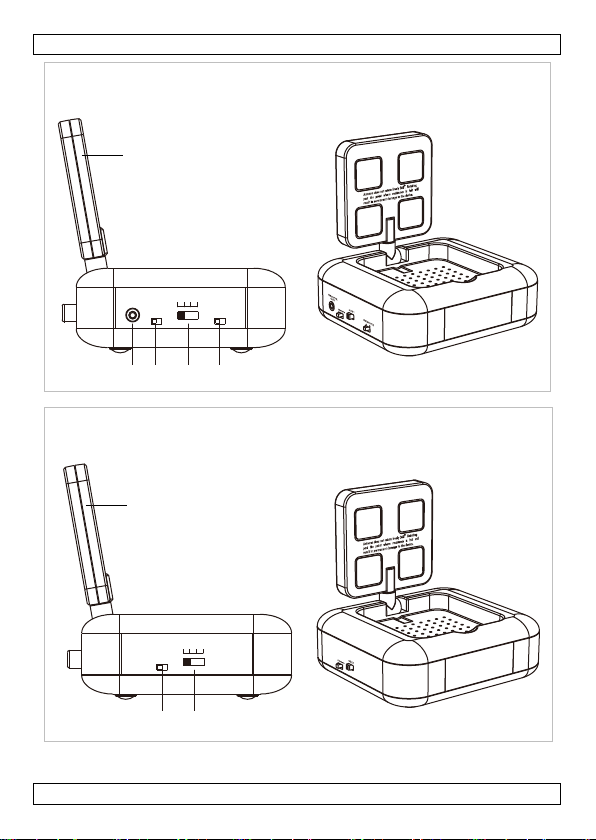
A 5.8 GHz antenna (folded upwards)
B channel selector switch
C ON/OFF switch
D infrared remote output (transmitter only)
E remote frequency selector (transmitter only) A = 38 kHz; B = 56 kHz
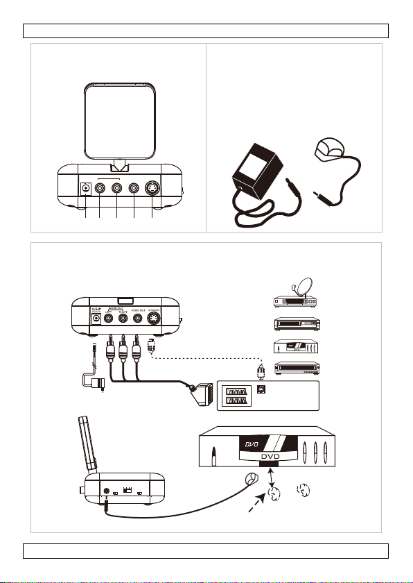
F power connector (12 VDC)
G S-video connector
H RCA video connector (yellow)
I RCA audio connector R (red)
J RCA audio connector L (white)
K power adaptor (2 x)
L IR LED
1 – side view
2 – rear view
3 – accessories
6. Installation
Refer to the illustrations on pages 2-5 of this manual. Make sure all devices are
disconnected from the mains before making any connections.
Transmitter [5]
The transmitter can be recognized easily as it has an IR output port [D] and
remote frequency selector [E] at the side.
1. Use the SCART-to-RCA A/V cable ma rked with TRANSMITTER (included) or
use an appropriate S-video cable (not inc luded).
Note: When using an S-video cable, the RCA connectors are disabled. Alway s use
an S-video cable on both transmitter and receiver.
2. Connect the RCA video connector (yellow) to the video connector [H] and
connect the audio connectors (red, white) to the audio connectors [I]
resp. [J]. When using an S-video cable, simply connect it to the S-video
connector [G].
3. Connect the SCART connector to a SCART output connector or connect the
free end of the S-video cable to the S-video output port of the signal
transmitting device (e.g. satellite receiver, DVD, VCR…, not incl.).
V. 02 – 17/09/2012 7 ©Velleman nv
Page 8

AVMOD19
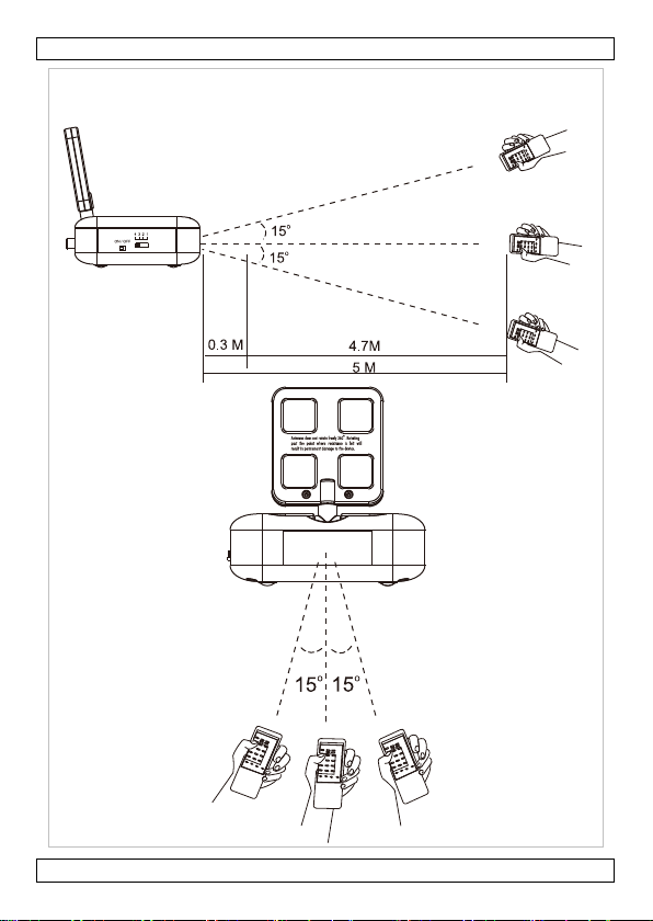
4. Connect the IR extender connector to the IR remote output port [D]. Place
the IR LED [L] in front of the IR receiver of the signal transmitting device,
maximum distance ± 50 cm (± 20”), angle +/-15°.
5. Plug the power plug of the included AC power adaptor [K] into the power
connector [F]. Only use the included adaptor or one with the same
specifications.
6. Make sure the power switch [C] is in the OFF-position and plug the adaptor
into a suitable mains outlet.
Note: Make sure the power adapter is easily accessible. Always disconnect the
mains power when the device is not in use.
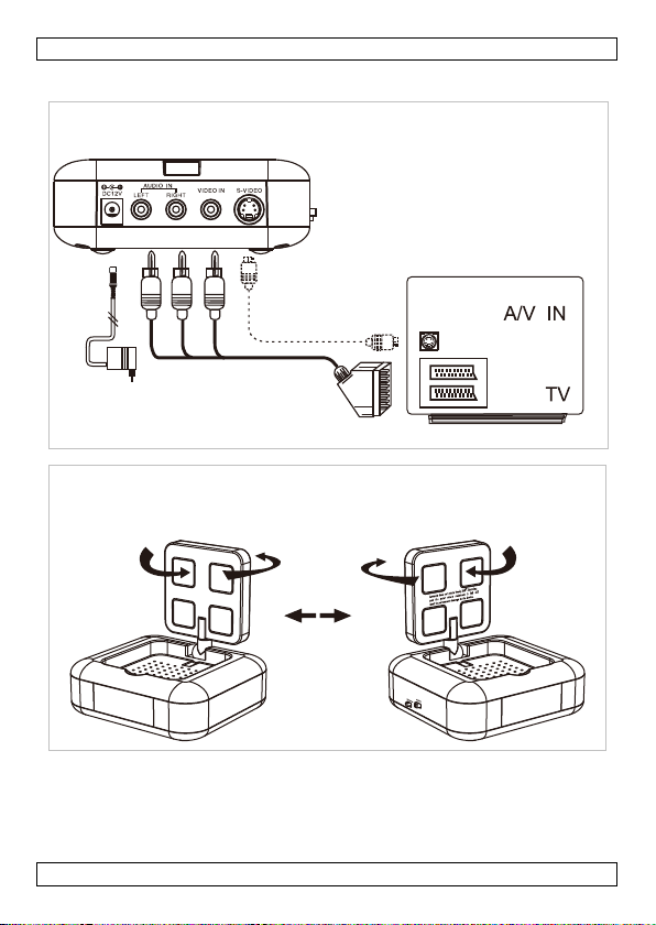
Receiver [6]
1. Use the SCART-to-RCA A/V cable ma rked with RECEIVER (included) or use
an appropriate S-video cable (not included).
Note: When using an S-video cable on the transmitter side, an S-video cable
must also be used on the receiver side.
2. Connect the RCA video connector (yellow) to the video connector [H] and
connect the audio connectors (red, white) to the audio connectors [I]
resp. [J]. When using an S-video cable, simply connect it to the S-video
connector [G].
3. Connect the SCART connector to a SCART input connector or connect the free
end of the S-video cable to the S-video output port of a TV, m onitor... (not
included).
4. Plug the power plug of the included AC power adaptor [K] into the power
connector [F]. Only use the included adaptor or one with the same
specifications.
5. Make sure the power switch [C] is in the OFF-position and plug the adaptor
into a suitable mains outlet.
Note: Make sure the power adapter is easily accessible. Always disconnect the
mains power when the device is not in use.
7. Operation
1. Switch on the receiver and transmitter [C].
2. Fold the antennas upwards and position them in such a way that the side with
the grooves of the receiver and transmitter antennas face each other [7].
This will guarantee best performance.
Notes:
o The antenna does not rotate 360°. Do not force or rotate past the
protrusion or permanent damage will occur.
o Avoid obstacles between the antenn as as this will decrease performance.
o Keep the distance from transmitter to receiver antenna as short as
possible.
3. Use the channel selector switch [B] to set the channel. Select a channel
depending on noise or interference conditions. Always set the same channel
on transmitter and receiver.
4. Point the remote control towards the receiver (see [8]) to control the
transmitting device(s). In case interference with other IR devices is noticed,
set the remote frequency selector [E] in the other position. In A-mode, the
carrier frequency is 38 kHz; in B-mode 56 kHz.
V. 02 – 17/09/2012 8 ©Velleman nv
Page 9
AVMOD19
8. Troubleshooting
No picture or sound
• Make sure all connections are made properly (following this manual) and all
devices are switched on.
• Make sure the same channel is set on receiver and transmitter.
• In case of S-video, make sure the mode on the TV is set correctly (refer to
the user manual of the TV).
Interference/noise
• Adjust antenna direction of receiver and transmitter for optimal performance.
• Make sure t he adaptor input voltage is > 220 VAC.
• Select different channel (on both receiver and transmitter!).
• Change position of the receiver and/or transmitter.
• When transmitter and receiver are < 10 m apart, do not unfold the antennas.
• Switch off microwave ovens.
Remote control doesn’t work
• Aim the remote control towards the receiver (see [8]) and press and hold the
button for ±1 second.
• Make sure the IR LEDs are pointing towards the sensor(s) of the transmitting
device(s).
• Make sure the batteries of the remote control are fully charged.
9. Maintenance
• Disconnect the devices from the mains prior to maintenance activities.
• Wipe the device regularly with a moist, lint-free cloth. Do not use alcohol or
solvents.
• Contact your dealer for spare parts if necessary.
10. Technical Specifications
frequency 5.8 GHz
transmission range ± 50 m (clear line of sight)
transmitter
frequency 5790 - 5828 - 5847 - 5866 MHz
channel selection 4 channels, switch on side
type of modulation FM (video and audio)
video input level 1 Vpp (RCA connector)
audio input level 1 Vpp (RCA connector)
S-video input level Y: 1 Vpp ± 10%, C: 288 mV ± 5% (SVHS connector)
video input impedance 75 ohms
audio input impedance 2 kilohms
power supply 12 VDC / 250 mA (adaptor included)
dimensions 120 x 100 x 43 mm
weight 200 g
IR transmitter
frequency 433.92 MHz
demodulation type AM
V. 02 – 17/09/2012 9 ©Velleman nv
Page 10
7
p
p
u
d
b
i
p
m
r
s
o
g
e
k
Dlhht
n
g
r
r
e
n
:
2
220
ufre
i
o
w
m
n
f
e
U
m
i
e
e
e
1
d
:
a
m
d
e
y
s
n
e
r
e
g
e
o
o
S
n
o
s
o
l
d
o
N
n
k
n
d
e
n
u
o
n
o
j
a
e
receiver
video out
audio out
S-video o
power sup
dimension
weight
IR receive
Use this
responsi
use of th
For more
manual,
The infor
© COPYR
The copy
rights re
reduced t
the copyri
ut level 1
ut level 1
tput level Y
ply 1
s 1
evice with orig
le in the event
s device.
info concerning
lease visit our
ation in this
IGHT NOTICE
ight to this ma
erved. No part o
any electronic m
ht holder.
AVMOD
Vpp ± 0.2 Vpp vi
Vpp ± 0.2 Vpp au
1 Vpp ± 20%, C
VDC / 250 mA (
0 x 100 x 43 m
0 g
b
ilt-in receiver
quency
nal accessories
f damage or inj
this product an
ebsite www.v
anual is subject
ual is owned b
this manual may
dium or otherwi
9
eo (RCA connect
dio (RCA connect
288 mV ± 5% (
daptor included)
433.92 MHz
only. Velleman
ury resulting fr
the latest ver
lleman.eu.
to change with
Velleman nv. A
be copied, repro
e without the pri
r)
r)
VHS connector)
v cannot be hel
m (incorrect)
ion of this
ut prior notice.
l worldwide
uced, translated
r written consent
d
r
of
1. Inl
Aan alle i
Belangrij
milieuwet
Hebt u v
verwijde
Dank u vo
gebruik n
dan niet e
V. 02 – 1
GEBR
iding
ngezetenen van
e milieu-infor
it symbool op he
evenscyclus word
et milieu. Gooi d
uishoudelijke afv
erechtkomen voo
aar een lokaal re
eving.
agen, contactee
ing.
or uw aankoop! L
emt. Werd het to
raadpleeg uw d
/09/2012
IKERSHA
de Europese U
atie betreffend
t toestel of de ve
t weggeworpen, d
t toestel (en even
al; het moet bij e
r recyclage. U mo
cyclagepunt bren
r dan de plaats
es deze handleidi
stel beschadigd t
aler.
10
NDLEIDI
ie
dit product
pakking geeft aa
it toestel schade
tuele batterijen)
n gespecialiseer
et dit toestel naar
en. Respecteer d
lijke autoriteite
ng grondig voor
ijdens het transp
G
dat, als het na zi
an toebrengen a
iet bij het gewon
bedrijf
uw verdeler of
plaatselijke
betreffend de
het toestel in
rt, installeer het
©Velleman
n
n
v
Page 11

7
o
r
ron
e
e
e
u
u
a
z
t
e
e
n
0
s
n
s
i
r
s
e
v
s
o
g
g
v
u
k
v
u
d
v
R
A
o
1
e
i
n
i
s
m
m
n
g
b
e
h
v
e
o
d
0
a
a
n
r
.
h
r
a
n
o
e
e
h
n
t
d
,
n
n
e
o
n
e
2. Veil
3. Alg
Raadpleeg
handleidin
• Leer
• Om v
wijzig
• Gebr
gebr
• De g
in de
defec
4. Eig
• draad
• de ge
frequ
• inhou
• optio
AVW
5. Om
Raadpleeg
A anten
B keuze
C aan-u
igheidsinstr
H
ud buiten het be
T
ek de stekker uit
to
estel reinigt en al
E
zijn geen door d
derhoud of reser
mene richtl
de Velleman®
g.
Gebruik het t
vochtigheid e
gevuld met vl
Bescherm te
Bescherm te
bediening.
erst de functies
iligheidsredenen
ingen die de gebr
ik het toestel en
ik vervalt de gara
rantie geldt niet
e handleiding en
en of problemen
nschappen
loze transmissie
bruikte frequentie
ntie van 2,4 GHz
d: 2 x scart naar
ele videokabels:
85, AVW085.
chrijving
de afbeeldingen
e 5,8 GHz
chakelaar kanaal
tschakelaar
AVMOD
ucties
eik van kinderen
het stopcontact (t
u het niet gebru
gebruiker verva
eonderdelen, con
ijnen
ervice- en kwal
estel enkel binn
n opspattende vlo
oeistof op of naa
en stof en extre
en schokken. Ver
an het toestel ke
mag u geen wijzi
iker heeft aange
el waarvoor het g
ntie.
oor schade door
w dealer zal de
ie hier rechtstre
an A/V signalen d
van 5,8 GHz ver
CA A/V, infraroo
VB020/2.0, AVB
p pagina’s 2-3 v
1 – zijaanz
9
n onbevoegden.
rek niet aan de k
kt.
gbare onderdele
tacteer uw deale
teitsgarantie ac
enshuis. Besche
eistoffen. Plaats g
t het toestel.
e temperaturen.
ijd brute kracht
nen voor u het g
ingen aanbrenge
racht valt niet on
maakt is. Bij on
et negeren van b
erantwoordelijkh
ks verband mee
oor muren en va
orzaakt minder s
module en 2 voe
20/5.0, AVW084
n deze handleidi
icht
bel!) voordat u h
in dit toestel. Vo
teraan deze
m tegen regen,
een objecten
tijdens de
at gebruiken.
. Schade door
der de garantie.
ordeelkundig
paalde richtlijne
id afwijzen voor
ouden.
kamer naar kam
oring dan de
ingsadapters
AVW084G,
g.
t
r
V. 02 – 1
/09/2012
11
©Velleman
v
Page 12

AVMOD19
D aansluiting infraroodoog (enkel zender)
E keuzeschakelaar frequentie (enkel zender) A = 38 kHz; B = 56 kHz
F voedingsaansluiting (12 VDC)
G aansluiting S-video
H RCA videoaansluiting (geel)
I RCA audioaansluiting R (rood)
J RCA audioaansluiting L (wit)
K voeding (2 x)
L IR-led
2 – achteraanzicht
3 – accessoires
6. Installatie
Raadpleeg de afbeeldingen op pagina’s 2-5 van deze handleiding. Ontkoppel eerst
alle toestellen van het lichtnet.
Zender [5]
De zender is uitgerust met een aansluiting [D] voor de IR-led en een
keuzeschakelaar voor de frequentie [E].
1. Gebruik de aansluitkabel met het opschrift TRANSMITTER (scart naar RCA)
(meegeleverd) of gebruik een aangepaste S-video-kabel (niet m eegeleverd).
Opmerking: Bij gebruik van een S-video-kabel zullen de RCA-aansluitingen
ontkoppeld worden. Gebruik dus een S-video-kabel voor zowel de zender als de
ontvanger.
2. Sluit de gele RCA-stekker aan de videoaansluiting [H], en de rode en witte
audiostekker aan de audioaansluitingen [I] resp. [J]. Sluit een S-video-kabel
gewoonweg aan de S-video-aansluiting [G].
3. Sluit de scartstekker aan de scartuitgang of sluit de vrije S-video-stekker aan
de S-video-uitgang van het zendtoestel (bv. satellietontvanger, dvd-speler…,
niet meegeleverd).
4. Sluit het infraroodoog aan de aansluiting [D]. Plaats de led [L] voor de
ontvanger van het zendtoestel, op een afst and van maximaal 50 cm, in een
hoek van ± 15°.
5. Steek de voedingsstekker van de meegeleverde adapter [K] in de
voedingsaansluiting [F]. Gebruik enkel de meegeleverde adapter of een
adapter met dezelfde specificaties.
6. Plaats de aan-uitschakelaar [C] op OFF en koppel de adapter aan het lichtnet.
Opmerking: Zorg ervoor dat de adapter goed toegankelijk is. Trek de stekker
altijd uit het stopcontact als u het apparaat niet gebruikt.
Ontvanger [6]
1. Gebruik de aansluitkabel met het opschrift RECEIVER (scart naar RCA)
(meegeleverd) of gebruik een aangepaste S-video-kabel (niet m eegeleverd).
Opmerking: Gebruik, indien u een S-video-kabel aansluit aan de zender, ook een
S-video-kabel voor de ontvanger.
V. 02 – 17/09/2012 12 ©Velleman nv
Page 13

AVMOD19
2. Sluit de gele RCA-stekker (yellow) aan de videoaansluiting [H], en de rode en
witte audiostekker aan de audioaansluitingen [I] respectievelijk [J]. Sluit een
S-video-kabel gewoonweg aan de S-video-aansluiting [G].
3. Sluit de scartstekker aan de scartingang of sluit de vrije S-video-stekker aan
de S-video-ingang van een tv-toestel, monitor… (niet meegeleverd).
4. Steek de voedingsstekker van de meegeleverde voedingsadapter [K] in de
voedingsaansluiting [F]. Gebruik enkel de meegeleverde adapter of een
adapter met dezelfde specificaties.
5. Plaats de aan-uitschakelaar [C] op OFF en koppel de adapter aan het lichtnet.
Opmerking: Zorg ervoor dat de adapter goed toegankelijk is. Trek de stekker
altijd uit het stopcontact als u het apparaat niet gebruikt.
7. Gebruik
1. Schakel de ontvanger en de zender in [C].
2. Vouw de antennes open en richt de gegroefde zijdes naar elkaar [7] voor de
beste ontvangst.
Opmerkingen:
o De antennes kunnen niet over een hoek van 360° ronddraaien. Draai de
antennes zachtjes naar elkaar toe.
o Verwijder elk object tussen de twee antennes.
o Houd de afstand tussen de twee antennes zo kort mogelijk.
3. Stel het kanaal in met de keuzeschakelaar [B]. Selecteer het kanaal met de
beste ontvangst en de minste storing. Selecteer nu ook datzelfde kanaal op
de ontvanger.
4. Richt de afstandsbediening naar de ontvanger (zie [8]) en bedien zo de
toestellen. Kies met de keuzeschakel aar [E] een andere frequentie
(A = 38 kHz; B = 56 kHz) indien er storing optreedt.
8. Problemen en oplossingen
Geen beeld, geen geluid
• Controleer alle aansluitingen en schakel alle toestellen in.
• Selecteer hetzelfde kanaal op zowel de zender als de ontvanger.
• Zorg ervoor dat u bij gebruik van S-video-kabels het tv-toestel in de correcte
modus plaatst. Raadpleeg de handleiding van uw tv-toestel.
Storing
• Verplaats de antennes van de zender en ontvanger lichtjes.
• Koppel de voedingsadapter aan een spanning van minstens 220 VAC.
• Selecteer een andere frequentie op de zender en de ontvanger.
• Verplaats de zender en/of de ontvanger.
• Vouw de antennes niet open indien de afstand tussen zender en ontvanger
kleiner is dan 10 m.
• Schakel alle magnetrons uit.
Afstandsbediening functioneert niet
• Richt de afstandsbediening naar de ontvanger (zie [8]) en houd de knop
gedurende 1 seconde ingedrukt.
• Zorg ervoor dat de infraroodogen naar de sensor gericht staan.
• Gebruik de afstandsbediening met nieuwe batterijen.
V. 02 – 17/09/2012 13 ©Velleman nv
Page 14

AVMOD19
9. Reiniging en onderhoud
• Ontkoppel de toestellen van het lichtnet alvorens het toestel schoon te
maken.
• Maak het toestel geregeld schoon met een vochtig, niet-pluizend doek.
Gebruik geen alcohol of solventen.
• Bestel eventuele reserveonderdelen bij uw plaatselijke v erdeler.
10. Technische specificaties
frequentie 5,8 GHz
zendbereik ± 50 m (zonder obstakels)
zender
frequentie 5790 - 5828 - 5847 - 5866 MHz
kanaalkeuze 4 kanalen via keuzeschakelaar
modulatie FM (video en audio)
video-ingang 1 Vpp (RCA-aansluiting)
audio-ingang 1 Vpp (RCA-aansluiting)
S-video-ingang Y: 1 Vpp ± 10%, C: 288 mV ± 5% (SVHS-aansluiting)
impedantie video-ingang 75 ohm
impedantie audio-ingang 2 kilohm
voeding 12 VDC / 250 mA (adapter meegelev.)
afmetingen 120 x 100 x 43 mm
gewicht 200 g
IR-zender
ontvanger
video-uitgang 1 Vpp ± 0,2 Vpp (RCA-aansluiting)
audio-uitgang 1 Vpp ± 0,2 Vpp (RCA-aansluiting)
S-video-uitgang Y: 1 Vpp ± 20%, C: 288 mV ± 5% (SVHS-aansluiting)
voeding 12 VDC / 250 mA (adapter meegelev.)
afmetingen 120 x 100 x 43 mm
gewicht 200 g
IR-ontvanger
Gebruik dit toestel enkel met originele accessoires. Velleman nv is niet
aansprakelijk voor schade of kwetsuren bij (verkeerd) gebruik van dit
toestel.
Voor meer informatie over dit product en de laatste versie van deze
handleiding, zie www.velleman.eu.
De informatie in deze handleiding kan te allen tijde worden gewijzigd
zonder voorafgaande kennisgeving.
frequentie 433,92 MHz
demodulatie AM
ingebouwde ontvanger
frequentie 433,92 MHz
V. 02 – 17/09/2012 14 ©Velleman nv
Page 15

7
R
j
k
r
d
Caadf
a
e
a
é
o
e
e
t
j
r
v
a
M
e
n
a
e
u
t
u
v
t
o
r
e
é
o
e
p
e
r
p
1
n
m
M
p
e
(
r
c
d
t
l
r
e
u
n
s
r
r
g
v
o
t
é
g
v
n
é
p
t
®
P
c
n
n
h
© AUTEU
Velleman
wereldwi
handleidin
bewerken
schriftelij
SRECHT
nv heeft het au
de rechten voo
g of gedeelten er
en op te slaan op
e toestemming v
AVMOD
eursrecht voor
behouden. Het i
an over te neme
een elektronisch
n de rechthebben
9
deze handleidin
s niet toegestaan
, te kopiëren, te
edium zonder v
de.
. Alle
om deze
ertalen, te
orafgaande
1. Int
Aux rési
Des infor
réglement
En cas d
Nous vous
la mise en
transport,
2. Con
3. Dir
Se référer
V. 02 – 1
oduction
ents de l'Union
mations enviro
e symbole sur l'
ppareil en fin de
ppareil électriqu
échets municipa
l’appareil en ques
ournisseur ou à
tion locale relati
questions, con
remercions de v
service de l’appa
ne pas l’installer
signes de s
G
rder hors de la p
D
brancher l’appar
p
ur débrancher l'a
Il
n’y a aucune pièc
d
rechange éventu
ctives géné
à la garantie de
Utiliser cet a
de l’humidité
contenant un
Protéger cont
/09/2012
ODE D’E
uropéenne
nementales im
ppareil ou l'emba
vie peut polluer l'
ou électronique
x non sujets au t
ion. Renvoyer les
n service de recy
e à la protection
acter les autori
tre achat ! Lire la
eil. Si l’appareil a
t consulter votre
curité
rtée des enfants
il s’il n’est pas uti
pareil ; non pas
maintenable pa
elles chez votre r
ales
service et de q
pareil uniqueme
et des projection
liquide sur l’appa
re la poussière. P
15
PLOI
ortantes concer
llage indique que
nvironnement. N
et des piles éven
i sélectif ; une d
équipements usa
lage local. Il con
e l’environneme
és locales pour
présente notice a
été endommagé
revendeur.
et des personnes
lisé ou pour le ne
e câble.
l’utilisateur. Com
vendeur.
alité Velleman
t à l'intérieur.
d’eau. Ne jamais
eil.
otéger contre la
nant ce produit
l’élimination d’un
e pas jeter un
uelles) parmi les
chèterie traitera
és à votre
ient de respecter
t.
limination.
ttentivement ava
endant le
non autorisées.
toyer. Tirer la fic
mander des pièce
en fin de notice.
rotéger de la plui
placer d’objet
haleur extrême.
©Velleman
la
t
e
s
e,
v
Page 16

AVMOD19
Protéger contre les chocs et le traiter avec circonspection pendant
l’opération.
• Se familiariser avec le fonctionnement avant l’emploi.
• Toute modification est interdite pour des raisons de sécurité. Les dommages
occasionnés par des modifications par le client ne tombent pas sous la
garantie.
• N’utiliser qu’à sa fonction prévue. Un usage impropre annule d'office la
garantie.
• La garantie ne s’applique pas aux dommages survenus en négligeant
certaines directives de cette notice et votre revendeur déclinera toute
responsabilité pour les problèmes et les défauts qui en résultent.
4. Caractéristiques
• transmission sans fil de signaux A/V à travers de murs et d'une pièce à l'autre
• la fréquence utilisée de 5,8 GHz engendre moins d’interférence qu’une
fréquence de 2,4 GHz
• livré avec 2 câbles péritel vers RCA A/V, module IR et 2 blocs secteur
• câble vidéo optionnel : AVB020/2.0, AVB020/5.0, AVW084, AVW084G,
AVW085, AVW085.
5. Description
Se référer aux illustrations en pages 2-3 de cette notice.
1 – vue latérale
A antenne 5,8 GHz
B sélecteur de canal
C interrupteur marche/arrêt
D sortie pour œil infrarouge (émetteur uniquement)
E sélecteur de fréquence (émetteur uniquement) A = 38 kHz ; B = 56 kHz
2 – vue arrière
F prise d’alimentation (12 VCC)
G prise S-vidéo
H prise RCA vidéo (jaune)
I prise RCA audio R (rouge)
J prise RCA audio L (blanc)
3 – accessoires
K bloc secteur (2 x)
L LED IR
6. Installation
Se référer aux illustrations en pages 2-5 de cette notice. Déconnecter tous les
appareils du réseau avant de commencer la connexion.
Émetteur [5]
L’émetteur est muni d’une connexion [D] pour la LED IR et d’un sélecteur de
fréquence [E].
V. 02 – 17/09/2012 16 ©Velleman nv
Page 17

AVMOD19
1. Utiliser le câble A/V péritel vers RCA marqué TRANSMITTER (inclus) ou
utiliser un câble S-vidéo adapté (non inclus).
Remarque : Les connexions RCA sont désactivées lors de l’utilisation de câbles Svidéo. Toujours utiliser un câble S-vidéo sur l’émetteur et le récepteur.
2. Insérer la fiche RCA jaune dans la prise vidéo [H], et insérer les fiches audio
rouge et blanche dans les prises audio [I] et [J]. Connecter un câble S-vidéo
à la prise [G].
3. Insérer la fiche péritel dans la sortie péritel ou connecter la fiche S-vidéo libre
à la sortie S-vidéo de votre récepteur satellite, lecteur DVD, enregistreur…
(non inclus).
4. Connecter l’œil infrarouge à la sortie IR [D]. Placer l’œil [L] à une distance
maximale de 50 cm du récepteur IR de votre appareil (dans un angle de
± 15°).
5. Insérer la fiche d’alimentation du bloc secteur [K] dans la prise d’alimentation
[F]. N’utiliser que le bloc secteur inclus.
6. Placer l’interrupteur d’alimentation [C] en position OFF et connecter le bloc
secteur au réseau électrique.
Remarque : S'assurer que le bloc secteur soit facilement accessible. Toujours
débrancher l’appareil s’il n’est pas utilisé.
Récepteur [6]
1. Utiliser le câble A/V péritel vers RCA marqué RECEIVER (inclus) ou utiliser
un câble S-vidéo adapté (non inclus).
Remarque : Toujours utiliser un câble S-vidéo su r l’émetteur et le récepteur.
2. Insérer la fiche RCA jaune dans la prise vidéo [H], et insérer les fiches audio
rouge et blanche dans les prises audio [I] et [J]. Connecter un câble S-vidéo
à la prise [G].
3. Insérer la fiche péritel dans l’entrée péritel ou connecter la fiche S-vidéo libre
à l’entrée S-vidéo de votre récepteur satellite, lecteur DVD, enregistreur…
(non inclus).
4. Insérer la fiche d’alimentation du bloc secteur [K] dans la prise d’alimentation
[F]. N’utiliser que le bloc secteur inclus.
5. Placer l’interrupteur d’alimentation [C] en position OFF et connecter le bloc
secteur au réseau électrique.
Remarque : S'assurer que le bloc secteur soit facilement accessible. Toujours
débrancher l’appareil s’il n’est pas utilisé.
7. Emploi
1. Allumer l’émetteur et le récepteur [C].
2. Déployer les antennes et les placer comme il lustré [7] afin de garantir la
meilleure réception.
Remarque :
o Les antennes ne sont pas rotatives sur 360°. Les déployer avec
précaution.
o Retirer tout objet entre les deux antennes.
o Réduire la distance entre les deux antennes le plus possible.
3. Sélectionner le canal avec le sélectionneur [B]. Choisir le canal offrant la
meilleure réception. Sélectionner la même fréquence sur l’émetteur et le
récepteur.
V. 02 – 17/09/2012 17 ©Velleman nv
Page 18

AVMOD19
4. Pointer la télécommande vers le récepteur (voir [8]) pour piloter l’appareil
A/V. En cas d’interférence, sélectionner l’autre fréquence à l’aide du sélecteur
[E] (A = 38 kHz ; B = 56 kHz).
8. Problèmes et solutions
Pas d’image, pas de son
• Vérifier les connexions et allumer les appareils.
• Sélectionner la même fréquence sur l’émetteur et le récepteur.
• Configurer dûment le téléviseur lors de l’utilisation de câbles S-vidéo (voir la
notice du téléviseur).
Interférence
• Rediriger les antennes de l’émetteur et/ou du récepteur.
• Connecter les blocs secteur à une source électrique de minimum 220 VCA.
• Sélectionner une autre fréquence.
• Déplacer l’émetteur et/ou le récepteur.
• Ne pas déployer les antennes lorsque la distance entre l’émetteur et le
récepteur est supérieure à 10 m.
• Éteindre les fours à micro-ondes.
La télécommande ne fonctionne pas
• Pointer la télécommande vers le récepteur (voir [8]) et maintenir enfoncé le
bouton pendant 1 seconde.
• Veiller à ce que les yeux IR soient dirigés vers les récepteurs IR des appareils
A/V.
• Vérifier le niveau des piles dans la télécommande.
9. Nettoyage et entretien
• Déconnecter les appareils du réseau électrique avant chaque entretien.
• Essuyer les appareils régulièrement avec un chiffon humide non pelucheux.
Éviter l’usage d’alcool et de solvants.
• Commander des pièces de rechange éventuelles chez votre revendeur.
10. Spécifications techniques
fréquence 5,8 GHz
portée de la transmission ± 50 m (sans obstacles)
émetteur
fréquence 5790 - 5828 - 5847 - 5866 MHz
sélection du canal 4 canaux depuis le sélecteur
modulation FM (vidéo et audio)
niveau d’entrée vidéo 1 Vpp (RCA)
niveau d’entrée audio 1 Vpp (RCA)
niveau de sortie S-vidéo Y : 1 Vpp ± 10%, C : 288 mV ± 5% (SVHS)
impédance d’entrée vidéo 75 ohms
impédance d’entrée audio 2 kilohm
alimentation 12 VCC/250 mA (bloc secteur incl.)
dimensions 120 x 100 x 43 mm
poids 200 g
V. 02 – 17/09/2012 18 ©Velleman nv
Page 19

7
I
r
o
y
d
d
s
i
s
S
m
o
o
e
o
r
d
n
d
o
n
q
c
g
e
c
e
p
o
d
s
n
N
n
b
a
p
o
n
c
o
e
t
1
,
(
m
e
d
r
v
d
t
s
i
r
a
e
m
d
L
d
d
%
)
e
e
c
è
u
t
o
r
c
e
v
p
a
n
a
t
a
t
e
o
émetteur
récepteu
niveau de
niveau de
niveau de
alimentati
dimension
poids
récepteur
N’emplo
ne peut,
responsa
résulter
Pour plu
cette not
Toutes le
modifiée
© DROIT
SA Velle
droits m
intégrale
support él
l’ayant dr
1. Int
A los ciu
Importa
producto
Si tiene
¡Gracias p
manual a
instale y p
V. 02 – 1
R
sortie vidéo
sortie audio
sortie S-vidéo
n
s
IR
er cet appareil
ans la mesure
ble des domma
e l’utilisation d
d’information
ce, visiter notr
s informations
sans notificati
D’AUTEUR
an est l’ayant
ndiaux réservé
u partielle, du co
ctronique que se
it.
MA
oducción
adanos de la U
tes informacion
Este símbolo en e
muestras inservi
No tire este apar
debe ir a una em
a su distribuidor
locales en relació
udas, contacte
r haber comprad
tes de usarlo. Si
óngase en contac
/09/2012
AVMOD
fréquence
démodulation
1 Vpp ± 0,2 Vpp
1 Vpp ± 0,2 Vpp
Y : 1 Vpp ± 20%
12 VCC/250 mA
120 x 100 x 43
200 g
récepteur intégré
fréquence
u’avec des acc
onforme au dro
es ou lésions (
cet appareil.
oncernant cet a
site web www.
résentées dans
n préalable.
roit des droits
. Toute reproduct
tenu de cette no
soit est interdite
UAL DEL
ión Europea
es sobre el med
ste aparato o el e
les, podrían daña
to (ni las pilas, si
resa especializad
a la unidad de r
con el medio a
on las autorida
el AVMOD19!
l aparato ha sufri
o con su distribui
19
9
433,92 MHz
AM
(RCA)
(RCA)
C : 288 mV ± 5
bloc secteur incl.
m
433,92 MHz
ssoires d’origin
it applicable êtr
irects ou indire
ticle et la derni
elleman.eu.
cette notice pe
’auteur pour ce
ion, traduction, c
ice par quelque p
ans l’accord préa
USUARIO
o ambiente con
mbalaje indica qu
el medio ambien
las hubiera) en la
en reciclaje. De
ciclaje local. Res
biente.
es locales para
ea atentamente l
o algún daño en
or.
(SVHS)
. La SA Vellem
tenue
ts) pouvant
re version de
vent être
te notice. Tous
pie ou diffusion,
océdé ou sur tou
lable écrit de
erniente a este
, si tira las
te.
basura doméstic
uelva este apara
ete las leyes
residuos.
s instrucciones d
el transporte no l
©Velleman
n
;
o
l
v
Page 20

7
t
a
ede
o
G
i
a
b
r
e
r
s
a
m
a
c
e
y
0
f
a
o
e
o
e
d
n
t
l
r
e
e
p
a
c
p
a
s
g
o
a
d
n
1
e
v
a
t
l
r
o
o
e
o
e
n
r
e
m
u
m
t
c
f
m
o
u
t
a
o
t
r
s
o
n
s
o
a
e
y
á
2. Ins
3. Nor
Véase la
usuario.
• Famil
• Por r
prohi
cubie
• Utilic
incor
• Daño
manu
ningú
4. Car
• trans
habit
• la fre
frecu
• inclu
• cable
AVW
5. Des
Véase las
A anten
B select
V. 02 – 1
rucciones d
M
ntenga el aparat
D
sconecte siempr
tiempo o antes
el
cable de red, nu
El
usuario no habrá
C
ntacte con su dis
mas genera
arantía de servi
Utilice el apa
lluvia, humed
ponga un obj
No exponga
temperaturas
No agite el a
la instalación.
arícese con el fun
zones de segurid
idas. Los daños
tos por la garantí
sólo el aparato
ecto anula la gar
causados por de
al invalidarán su
n daño u otros pr
cterísticas
isión inalámbric
ción a la otra
uencia utilizada
ncia de 2.4 GHz
e 2 cables SCART
de vídeo opcional
85, AVW085.
cripción
iguras en la pági
5,8 GHz
r de canal
/09/2012
AVMOD
seguridad
lejos del alcanc
el aparato si no
e limpiarlo. Tire s
ca del propio cabl
de efectuar el m
ribuidor si necesi
es
cio y calidad Ve
ato sólo en inte
ad ni a ningún tip
to con líquido en
ste equipo a polv
extremas.
arato. Evite usar
cionamiento del a
d, las modificaci
ausados por modi
a.
ara las aplicacion
ntía completame
cuido de las inst
arantía y su distr
blemas resultant
de señales A/V a
e 5.8 GHz causa
a RCA A/V, mód
: AVB020/2.0, AV
a 2 y 3 de este
1 – vista la
20
9
de personas no
a a usarlo durant
iempre del enchu
e.
ntenimiento de ni
a piezas de reca
leman ® al final
iores. No expong
de salpicadura
el aparato.
. No exponga est
xcesiva fuerza d
parato antes de u
nes no autorizad
ficaciones no aut
s descritas en es
te.
ucciones de segu
ibuidor no será re
s.
través de parede
enos interferenc
lo IR y 2 adaptad
B020/5.0, AVW08
anual del usuario
eral
apacitadas y niño
e un largo períod
e para desconect
nguna pieza.
bio.
de este manual d
a este equipo a
goteo. Nunca
e equipo a
rante el manejo
ilizarlo.
s del aparato est
rizadas, no están
e manual. Su uso
idad de este
ponsable de
s y de una
ias que una
res de red
4, AVW084G,
.
©Velleman
.
r
l
n
v
Page 21

AVMOD19
C interruptor ON/OFF
D salida para ojo infrarrojo (sólo emisor)
E selector de frecuencia (sólo emisor) A = 38 kHz; B = 56 kHz
F entrada de alimentación (12 VDC)
G entrada S-vídeo
H entrada RCA vídeo (amarillo)
I entrada RCA audio R (rojo)
J entrada RCA audio L (blanco)
K adaptador de red (2 x)
L LED IR
2 – vista posterior
3 – accesorios
6. Instalación
Véase las figuras en las páginas de 2 a 5 de este manual del usuario. Desconecte
todos los aparatos de la red antes de empezar.
Emisor [5]
El emisor está equipado con una conexión [D] para el LED IR y un selector de
frecuencia [E].
1. Utilice el cable A/V SCART a RCA indicado con TRANSMITTER (incl.) o utilice
un cable S-vídeo adecuado (no incl.).
Nota: Las conexiones RCA se desactivan al utilizar cables S-vídeo. Utilice siempre
un cable S-vídeo para el emisor y el receptor.
2. Introduzca el conector RCA amarillo en la entrada de vídeo [H], e introduzca
el conector de audio rojo y el conector de audio blanco en las entradas de
audio [I] y [J]. Conecte un cable S-vídeo a la entrada [G].
3. Introduzca el conector SCART en la salida SCART o conecte el conector S-
vídeo libre a la salida S-vídeo del receptor satélite, reproductor DVD,
videograbadora… (no incl.).
4. Conecte el ojo infrarrojo a la salida IR [D]. Ponga el ojo [L] a una distancia
máx. de 50 cm del receptor IR del aparato (en un ángulo de ± 15°).
5. Introduzca el conector de alimentación del adaptador de red [K] en la entrada
de alimentación [F]. Utilice sólo el adaptador de red incl.
6. Ponga el interruptor de alimentación [C] en la posición OFF y conecte el
adaptador de red a la red eléctrica.
Observación: Asegúrese de que el adaptador de red sea siempre fác ilmente
accesible. Desconecte siempre el aparato si no va a usarlo.
Receptor [6]
1. Utilice el cable A/V SCART a RCA indicado con RECEIVER (incl.) o utilice un
cable S-vídeo adaptado (no incl.).
Nota: Utilice siempre un cable S-vídeo para el emisor y el receptor.
2. Introduzca el conector RCA amarillo en la entrada de vídeo [H], e introduzca
el conector de audio rojo y el conector de audio blanco en las entradas de
audio [I] y [J]. Conecte un cable S-vídeo a la entrada [G].
V. 02 – 17/09/2012 21 ©Velleman nv
Page 22

AVMOD19
3. Introduzca el conector SCART en la salida SCART o conecte el conector S-
vídeo libre a la salida S-vídeo del receptor satélite, reproductor DVD,
videograbadora… (no incl.).
4. Introduzca el conector de alimentación del adaptador de red [K] en la entrada
de alimentación [F]. Utilice sólo el adaptador de red incl.
5. Ponga el interruptor de alimentación [C] en la posición OFF y conecte el
adaptador de red a la red eléctrica.
Observación: Asegúrese de que el adaptador de red sea siempre fác ilmente
accesible. Desconecte siempre el aparato si no va a usarlo.
7. Uso
1. Active el emisor y el receptor [L].
2. Despliegue las antenas y póngalos como está indicado [7] para garantizar la
mejor recepción.
Nota:
o No es posible girar las antenas unos 360°. Despliéguelas cuidadosamente.
o Quite cualquier objeto entre las dos antenas.
o Reduzca la distancia entre las dos antenas lo más posible.
3. Seleccione el canal con el selector [B]. Elija el canal que ofrece la mejor
recepción. Seleccione la misma frecuencia para el emisor y el receptor.
4. Apunte el mando a distancia al receptor (véase [8]) para controlar el aparato
A/V. En caso de interferencias, seleccione la otra frecuencia con el selector
[E] (A = 38 kHz; B = 56 kHz).
8. Solución de probl emas
No hay imagen, no hay sonido
• Controle las conexiones y active los aparatos.
• Seleccione la misma frecuencia para el emisor y el receptor.
• Configure el televisor correctamente al utilizar cables S-vídeo (véase el
manual del usuario del televisor).
Interferencias
• Vuelva a dirigir las antenas del emisor y/o el receptor.
• Conecte los adaptadores de red a una fuente eléctrica de mín. 220 VCA.
• Seleccione otra frecuencia.
• Desplace el emisor y/o el receptor.
• No despliegue las antenas si la distancia entre el emisor y el receptor es
superior a 10 m.
• Desactive los microondas.
El mando a distancia no funciona
• Apunte el mando a distancia al receptor (véase [8]) y mantenga pulsado el
botón durante 1 segundo.
• Asegúrese de que los ojos IR estén dirigidas hacia los receptores IR de los
aparatos A/V.
• Controle el nivel de las pilas del mando a distancia.
V. 02 – 17/09/2012 22 ©Velleman nv
Page 23

AVMOD19
9. Limpieza y mantenimiento
• Desconecte los aparatos de la red eléctrica antes de cada mantenimiento.
• Limpie los aparatos regularmente con un paño húmedo sin pelusas. Evite el
uso de alcohol y de disolventes.
• Contacte con su distribuidor si necesita piezas de recambio.
10. Especificaciones
frecuencia 5,8 GHz
rango de transmisión ± 50 m (sin obstáculos)
emisor
frecuencia 5790 - 5828 - 5847 - 5866 MHz
selección del canal 4 canales con el selector
modulación FM (vídeo y audio)
nivel de entrada vídeo 1 Vpp (RCA)
nivel de entrada audio 1 Vpp (RCA)
nivel de entrada S-vídeo Y: 1 Vpp ± 10%, C: 288 mV ± 5% (SVHS)
impedancia entrada de vídeo 75 ohm
impedancia entrada de audio 2 kilohm
alimentación 12 VDC / 250 mA (adaptador de red incl.)
dimensiones 120 x 100 x 43 mm
peso 200 g
emisor IR
receptor
nivel de salida vídeo 1 Vpp ± 0,2 Vpp (RCA)
nivel de salida audio 1 Vpp ± 0,2 Vpp (RCA)
nivel de salida S-vídeo Y: 1 Vpp ± 20%, C: 288 mV ± 5% (SVHS)
alimentación 12 VDC / 250 mA (adaptador de red incl.)
dimensiones 120 x 100 x 43 mm
peso 200 g
receptor IR
Utilice este aparato sólo con los accesorios originales. Velleman NV no
será responsable de daños ni lesiones causados por un uso (indebido) de
este aparato.
Para más información sobre este producto y la versión más reciente de
este manual del usuario, visite nuestra página www.velleman.eu.
Se pueden modificar las especificaciones y el contenido de este manual
sin previo aviso.
© DERECHOS DE AUTOR
Velleman NV dispone de los derechos de autor para este manual del
usuario. Todos los derechos mundiales reservados. Está estrictamente
prohibido reproducir, traducir, copiar, editar y guardar este manual del usuario o
partes de ello sin previo permiso escrito del derecho habiente.
V. 02 – 17/09/2012 23 ©Velleman nv
frecuencia 433,92 MHz
demodulación AM
receptor incorporado
frecuencia 433,92 MHz
Page 24

7
f
DESBB
e
r
e
B
g
s
w
h
a
rNe
sIh
g
m
t
E
t
f
k
s
v
D
o
w
b
.
w
n
r
h
-
i
g
e
m
e
I
e
m
1
o
e
s
s
R
f
9
g
a
m
t
e
a
S
G
n
e
G
u
e
c
o
i
r
e
r
n
e
h
e
d
m
d
r
ä
n
n
r
s
1. Ein
An alle Ei
Wichtige
RecyclingUmweltvo
Falls Zw
örtliche
Wir bedan
Bedienun
Transport
nicht und
2. Sic
3. Allg
Siehe Vell
Bedienun
• Neh
Funk
BEDI
ührung
nwohner der Eu
Umweltinforma
ieses Symbol au
ntsorgung dieses
chaden zufügen
atterien) nicht al
atterien müssen
ntsorgt werden.
Unternehmen ret
schriften.
ifel bestehen,
ehörde.
ken uns für den K
sanleitung vor In
chäden vorliegen
enden Sie sich a
erheitshin
H
lten Sie Kinder u
T
ennen Sie das Ge
tz. Fassen Sie da
Si
e nie an der Netzl
E
gibt keine zu wa
rem Fachhändler.
emeine Ric
eman® Service
sanleitung.
Verwenden S
Gerät vor Re
befüllten Geg
Schützen Sie
extremen Te
Vermeiden Si
während der
en Sie das Gerät
ionen vertraut ge
AVMOD
NUNGSA
ropäischen Uni
ionen über dies
dem Produkt ode
Produktes nach s
ann. Entsorgen S
unsortiertes Hau
on einer speziali
iese Einheit mus
urniert werden.
enden Sie sich
auf des AVMOD1
etriebnahme sor
Sollte dies der F
n Ihren Händler.
eise
d Unbefugte vo
rät bei Nichtbenu
zu den Netzsteck
eitung.
tenden Teile. Bes
tlinien
und Qualitätsg
e das Gerät nur i
en und Feuchte.
nstände auf das
das Gerät vor Sta
peraturen.
Erschütterunge
nstallation und B
rst in Betrieb, na
acht haben.
9
NLEITUN
n
es Produkt
r der Verpackung
inem Lebenszykl
ie die Einheit (od
smüll; die Einheit
ierten Firma zwe
an den Händler
espektieren Sie d
ür Entsorgungs
! Lesen Sie dies
fältig durch. Übe
ll sein, verwende
Gerät fern.
zung und vor jed
r an der Grifffläc
tellen Sie eventu
rantie am Ende
m Innenbereich
tellen Sie keine
erät.
ub. Schützen Sie
. Vermeiden Sie
dienung des Ger
chdem Sie sich m
zeigt an, dass die
s der Umwelt
r verwendeten
oder verwendete
ks Recycling
der ein örtliches
e örtlichen
ichtlinien an Ih
prüfen Sie, ob
Sie das Gerät
r Reinigung vom
e an und ziehen
lle Ersatzteile bei
ieser
. Schützen Sie da
it Flüssigkeit
as Gerät vor
ohe Gewalt
tes.
it seinen
e
V. 02 – 1
/09/2012
24
©Velleman
v
Page 25

AVMOD19
• Eigenmächtige Veränderungen sind aus Sicherheitsgründen verboten. Bei
Schäden verursacht durch eigenmächtige Änderungen erlischt der
Garantieanspruch.
• Verwenden Sie das Gerät nur für Anwendungen beschrieben i n dieser
Bedienungsanleitung sonst kann dies zu Schäden am Produkt führen und
erlischt der Garantieanspruch.
• Bei Schäden, die durch Nichtbeachtung der Bedienungsanleitung verursacht
werden, erlischt der Garantieanspruch. Für daraus resulti eren de Folgeschäden
übernimmt der Hersteller keine Haftung.
4. Eigenschaften
• überträgt drahtlos klare A/V-Signale durch Wände und im ganzen Haus
• die verwendete Frequenz von 5.8 GHz verursacht weniger Störung als eine
Frequenz von 2.4 GHz
• Lieferumfang: 2 x Scart auf RCA A/V, IR-Modul und 2 Netzteile
• optionale Videokabel: AVB020/2.0, AVB020/5.0, AVW084, AVW084G,
AVW085, AVW085
5. Umschreibung
Siehe Abbildungen, Seite 2 und 3 dieser Bedienungsanleitung.
A Antenne 5,8 GHz
B Wählschalter kanaal
C EIN/AUS-Schalter
D Anschluss IR-Auge (nur Sender)
E Wählschalter Frequenz (nur Sender) A = 38 kHz; B = 56 kHz
F Netzanschluss (12 VDC)
G Anschluss S-Video
H RCA Video-Anschluss (gelb)
I RCA Audio-Anschluss R (rot)
J RCA Audio-Anschluss L (weiß)
K Netzteil (2 x)
L IR-LED
1 – Seitenansicht
2 – Hinteransicht
3 – Zubehör
6. Installation
Siehe Abbildungen, Seite 2-5. Trennen Sie zuerst alle Geräte vom Netz.
Sender [5]
Der Sender verfügt über einen Anschluss [D] für die IR-LED und einen
Wählschalter für die Frequenz [E].
1. Verwenden Sie das Anschlusskabel mit der Aufschrift TRANSMITTER (Scart
auf RCA) (mitgeliefert) oder verwenden Sie ein geeignetes S-Video-Kab el
(nicht mitgeliefert).
V. 02 – 17/09/2012 25 ©Velleman nv
Page 26

AVMOD19
Bemerkung: Bei Anwendung eines S-Video-Kabels werden die RCA-Anschlüsse
getrennt. Verwenden Sie also ein S-Video-Kabel für sowohl den Sender als den
Empfänger.
2. Verbinden Sie den gelben RCA-Stecker mit dem Video-Anschluss [H], und
den roten und den weißen Audiostecker mit den Audio-Anschlüssen [I] und
[J]. Verbinden Sie ein S-Video-Kabel einfach mit dem S-Video-Anschluss [G].
3. Verbinden Sie den Scartstecker mit dem Scartausgang oder verbinden Sie den
freien S-Video-Stecker mit dem S-Video-Ausgang des Sendegerätes (z.B.
Satellitenempfänger, DVD-Spieler…, nicht mitgeliefert).
4. Verbinden Sie das IR-Auge mit dem Anschluss [D]. Stellen Sie die LED [L]
vor dem Empfänger des Sendegerätes, in einem Abstand von max. 50 cm, in
einem Winkel von ± 15°.
5. Stecken Sie den Stecker des mitgelieferten Netzteils [K] in den Netzanschluss
[F]. Verwenden Sie nur das mitgelieferte Netzteil oder ein Netzteil mit
denselben technischen Daten.
6. Stellen Sie den EIN/AUS-Schalter [C] auf OFF und verbinden Sie das Netzteil
mit dem Netz.
Bemerkung: Stellen Sie sicher, dass das Netzteil immer leicht zugänglich ist.
Trennen Sie das Gerät bei Nichtbenutzung vom Netz.
Empfänger [6]
1. Verwenden Sie das Anschlusskabel mit der Aufschrift RECEIVER (Scart auf
RCA) (mitgeliefert) oder verwenden Sie ein geeignetes S-Video-Kabel (nicht
mitgeliefert).
Bemerkung: Verwenden Sie, wenn Sie ein S-Video-Kabel mit dem Sender
verbinden, auch ein S-Video-Kabel für den Empfänger.
2. Verbinden Sie den gelben RCA-Stecker (Gelb) mit dem Video-Anschluss [H],
und den roten und weißen Audiostecker mit den Audio-Anschlüssen [I] und
[J]. Verbinden Sie ein S-Video-Kabel einfach mit dem S-Video-Anschluss [G].
3. Verbinden Sie den Scartstecker mit dem Scarteingang oder verbinden Sie den
freien S-Video-Stecker mit dem S-Video-Eingang des Fernsehers, Monitors…
(nicht mitgeliefert).
4. Stecken Sie den Stecker des mitgelieferten Netzteils [K] in den Netzanschluss
[F]. Verwenden Sie nur das mitgelieferte Netzteil oder ein Netzteil mit
denselben technischen Daten.
5. Stellen Sie den EIN/AUS-Schalter [C] auf OFF und verbinden Sie das Netzteil
mit dem Netz.
Bemerkung: Stellen Sie sicher, dass das Netzteil immer leicht zugänglich ist.
Trennen Sie das Gerät bei Nichtbenutzung vom Netz.
7. Anwendung
1. Schalten Sie den Empfänger und den Sender ein [C].
2. Falten Sie die Antennen auf und richten Sie die Seiten mit Rillen aufeinander
[7] für den besten Empfang.
Bemerkungen:
o Die Antennen können nicht über einen Winkel von 360° runddrehen.
Drehen Sie die Antennen vorsichtig nacheinander.
o Entfernen Sie jeden Gegenstand zwischen den zwei Antennen.
o Halten Sie den Abstand zwischen den zwei Antennen möglichst kurz.
V. 02 – 17/09/2012 26 ©Velleman nv
Page 27

AVMOD19
3. Stellen Sie den Kanal mit dem Wählschalter [B] ein. Wählen Sie den Kanal
mit dem besten Empfang und den geringsten Störungen. Wählen Sie nun
auch denselben Kanal für den Empfänger.
4. Richten Sie die Fernbedienung auf den Empfänger (siehe [8]) und bedienen
Sie so die Geräte. Wählen Sie mit dem Wählschalter [E] eine andere Frequenz
(A = 38 kHz; B = 56 kHz) aus wenn es Störungen gibt.
8. Problemlösung
Es gibt kein Bild, keinen Ton
• Überprüfen Sie alle Anschlüsse und schalten Sie alle Geräte ein.
• Wählen Sie denselben Kanal für sowohl den Sender als auch den Empfänger.
• Beachten Sie, dass Sie bei Anwendung von S-Video-kabeln den Fernseher in
den richtigen Modus stellen. Siehe die Bedienungsanleitung des Fernsehers.
Störungen
• Verstellen Sie die Antennen des Senders und Empfängers ein bisschen.
• Verbinden Sie das Netzteil mit einer Spannung von mindestens 220 VAC.
• Wählen Sie eine andere Frequenz für Sender und Empfänger.
• Verstellen Sie den Sender und/oder den Empfänger.
• Falten Sie die Antennen nicht auf wenn der Abstand wischen Sender und
Empfänger kleiner als 10 m ist.
• Schalten Sie alle Mikrowellen aus.
Die Fernbedienung funktioniert nicht
• Richten Sie die Fernbedienung auf den Empfänger (siehe [8]) und halten Sie
den Knopf 1 Sekunde gedrückt.
• Beachten Sie, dass die IR-Augen auf den Sensor gerichtet sind.
• Verwenden Sie die Fer nbe die nung mi t ne ue n Batte r ie n.
9. Reinigung und Wartung
• Trennen Sie de die Geräte vom Netz ehe Sie das Gerät reinigen.
• Verwenden Sie zur Reinigung ein feuchtes, fusselfreies Tuch. Verwenden Sie
auf keinen Fall Alkohol oder irgendwelche Lösungsmittel.
• Bestellen Sie eventuelle Ersatzunterteile bei Ihrem Fachhändler.
10. Technische Daten
Frequenz 5,8 GHz
Sendbereich ± 50 m (ohne Hindernisse)
Sender
Frequenz 5790 - 5828 - 5847 - 5866 MHz
Kanalwahl 4 Kanäle, über Wählschalter
Modulation FM (Video und Audio)
Video-Eingang 1 Vpp (RCA-Anschluss)
Audio-Eingang 1 Vpp (RCA-Anschluss)
S-Video-Eingang Y: 1 Vpp ± 10%, C: 288 mV ± 5% (SVHS-Anschluss)
Impedanz Video-Eingang 75 Ohm
Impedanz Audio-Eingang 2 kOhm
Stromversorgung 12 VDC / 250 mA (Netzteil mitgeliefert)
V. 02 – 17/09/2012 27 ©Velleman nv
Page 28

AVMOD19
Abmessungen 120 x 100 x 43 mm
Gewicht 200 g
IR-Sender
Empfänger
Video-Ausgang 1 Vpp ± 0,2 Vpp (RCA-Anschluss)
Audio-Ausgang 1 Vpp ± 0,2 Vpp (RCA-Anschluss)
S-Video-Ausgang Y: 1 Vpp ± 20%, C: 288 mV ± 5% (SVHS-Anschluss)
Stromversorgung 12 VDC / 250 mA (Netzteil mitgeliefert)
Abmessungen 120 x 100 x 43 mm
Gewicht 200 g
IR-Empfänger
Verwenden Sie dieses Gerät nur mit originellen Zubehörteilen. Velleman
NV übernimmt keine Haftung für Schaden oder Verletzungen bei
(falscher) Anwendung dieses Gerätes.
Für mehr Informationen zu diesem Produkt und die neueste Version
dieser Bedienungsanleitung, siehe www.velleman.eu.
Alle Änderungen ohne vorherige Ankündigung vorbehalten.
© URHEBERRECHT
Velleman NV besitzt das Urheberrecht für diese Bedienungsanleitung. Alle
weltweiten Rechte vorbehalten. Ohne vorherige schriftliche Genehmigung des
Urhebers ist es nicht gestattet, diese Bedienungsanleitung ganz oder in Teilen zu
reproduzieren, zu kopieren, zu übersetzen, zu bearbeiten oder zu speichern.
Frequenz 433,92 MHz
Demodulation AM
eingebauter Empfänger
Frequenz 433,92 MHz
V. 02 – 17/09/2012 28 ©Velleman nv
Page 29

Page 30

Page 31

Velleman® Service and Quality Warranty
Since its foundation in 1972, Velleman® acquired
extensive experience in the electronics world and currently
distributes its products in over 85 countries.
All our products fulfil strict quality requirements and legal
stipulations in the EU. In order to ensure the quality, our
products regularly go through an extra quality check, both
by an internal quality department and by specialized
external organisations. If, all precautionary measures
notwithstanding, problems should occur, please make
appeal to our warranty (see guarantee conditions).
General Warranty Conditions Concerning Consumer
Products (for EU):
• All consumer products are subject to a 24-month
warranty on production flaws and defective material as
from the original date of purchase.
• Velleman® can decide to replace an article with an
equivalent article, or to refund the retail value totally or
partially when the complaint is valid and a free repair or
replacement of the article is impossible, or if the expenses
are out of proportion.
You will be delivered a replacing article or a refund at the
value of 100% of the purchase price in case of a flaw
occurred in the first year after the date of purchase and
delivery, or a replacing article at 50% of the purchase
price or a refund at the value of 50% of the retail value in
case of a flaw occurred in the second year after the date
of purchase and delivery.
• Not covered by warranty:
- all direct or indirect damage caused after delivery to the
article (e.g. by oxidation, shocks, falls, dust, dirt,
humidity...), and by the article, as well as its contents (e.g.
data loss), compensation for loss of profits;
- consumable goods, parts or accessories that are subject
to an aging process during normal use, such as batteries
(rechargeable, non-rechargeable, built-in or replaceable),
lamps, rubber parts, drive belts... (unlimited list);
- flaws resulting from fire, water damage, lightning,
accident, natural disaster, etc.…;
- flaws caused deliberately, negligently or resulting from
improper handling, negligent maintenance, abusive use or
use contrary to the manufacturer’s instructions;
- damage caused by a commercial, professional or
collective use of the article (the warranty validity will be
reduced to six (6) months when the article is used
professionally);
- damage resulting from an inappropriate packing and
shipping of the article;
- all damage caused by modification, repair or alteration
performed by a third party without written permission by
Velleman®.
• Articles to be repaired must be delivered to your
Velleman® dealer, solidly packed (preferably in the
original packaging), and be completed with the original
receipt of purchase and a clear flaw description.
• Hint: In order to save on cost and time, please reread the
manual and check if the flaw is caused by obvious causes
prior to presenting the article for repair. Note that returning
a non-defective article can also involve handling costs.
• Repairs occurring after warranty expiration are subject to
shipping costs.
• The above conditions are without prejudice to all
commercial warranties.
The above enumeration is subject to modification
according to the article (see article’s manual).
Velleman® service- en kwaliteitsgarantie
Velleman® heeft sinds zijn oprichting in 1972 een ruime
ervaring opgebouwd in de elektronicawereld en verdeelt
op dit moment producten in meer dan 85 landen. Al onze
producten beantwoorden aan strikte kwaliteitseisen en
aan de wettelijke bepalingen geldig in de EU. Om de
kwaliteit te waarborgen, ondergaan onze producten op
regelmatige tijdstippen een extra kwaliteitscontrole, zowel
door onze eigen kwaliteitsafdeling als door externe
gespecialiseerde organisaties. Mocht er ondanks deze
voorzorgen toch een probleem optreden, dan kunt u
steeds een beroep doen op onze waarborg (zie
waarborgvoorwaarden).
Algemene waarborgvoorwaarden
consumentengoederen (voor Europese Unie):
• Op alle consumentengoederen geldt een garantieperiode
van 24 maanden op productie- en materiaalfouten en dit
vanaf de oorspronkelijke aankoopdatum.
• Indien de klacht gegrond is en een gratis reparatie of
vervanging van een artikel onmogelijk is of indien de
kosten hiervoor buiten verhouding zijn, kan Velleman®
beslissen het desbetreffende artikel te vervangen door
een gelijkwaardig artikel of de aankoopsom van het artikel
gedeeltelijk of volledig terug te betalen. In dat geval krijgt
u een vervangend product of terugbetaling ter waarde van
100% van de aankoopsom bij ontdekking van een gebrek
tot één jaar na aankoop en levering, of een vervangend
product tegen 50% van de kostprijs of terugbetaling van
50 % bij ontdekking na één jaar tot 2 jaar.
• Valt niet onder waarborg:
- alle rechtstreekse of onrechtstreekse schade na de
levering veroorzaakt aan het toestel (bv. door oxidatie,
schokken, val, stof, vuil, vocht...), en door het toestel,
alsook zijn inhoud (bv. verlies van data), vergoeding voor
eventuele winstderving.
- verbruiksgoederen, onderdelen of hulpstukken die
onderhevig zijn aan veroudering door normaal gebruik
zoals bv. batterijen (zowel oplaadbare als niet-oplaadbare,
ingebouwd of vervangbaar), lampen, rubberen
onderdelen, aandrijfriemen... (onbeperkte lijst).
- defecten ten gevolge van brand, waterschade, bliksem,
ongevallen, natuurrampen, enz.
- defecten veroorzaakt door opzet, nalatigheid of door een
onoordeelkundige behandeling, slecht onderhoud of
abnormaal gebruik of gebruik van het toestel strijdig met
de voorschriften van de fabrikant.
- schade ten gevolge van een commercieel, professioneel
of collectief gebruik van het apparaat (bij professioneel
gebruik wordt de garantieperiode herleid tot 6 maand).
- schade veroorzaakt door onvoldoende bescherming bij
transport van het apparaat.
- alle schade door wijzigingen, reparaties of modificaties
uitgevoerd door derden zonder toestemming van
Velleman®.
• Toestellen dienen ter reparatie aangeboden te worden
bij uw Velleman®-verdeler. Het toestel dient vergezeld te
zijn van het oorspronkelijke aankoopbewijs. Zorg voor een
Page 32

degelijke verpakking (bij voorkeur de originele verpakking)
en voeg een duidelijke foutomschrijving bij.
• Tip: alvorens het toestel voor reparatie aan te bieden,
kijk nog eens na of er geen voor de hand liggende reden
is waarom het toestel niet naar behoren werkt (zie
handleiding). Op deze wijze kunt u kosten en tijd
besparen. Denk eraan dat er ook voor niet-defecte
toestellen een kost voor controle aangerekend kan
worden.
• Bij reparaties buiten de waarborgperiode zullen
transportkosten aangerekend worden.
• Elke commerciële garantie laat deze rechten
onverminderd.
Bovenstaande opsomming kan eventueel aangepast
worden naargelang de aard van het product (zie
handleiding van het betreffende product).
Garantie de service et de qualité Velleman®
Depuis 1972, Velleman® a gagné une vaste expérience
dans le secteur de l’électronique et est actuellement
distributeur dans plus de 85 pays.
Tous nos produits répondent à des exigences de qualité
rigoureuses et à des dispositions légales en vigueur dans
l’UE. Afin de garantir la qualité, nous soumettons
régulièrement nos produits à des contrôles de qualité
supplémentaires, tant par notre propre service qualité que
par un service qualité externe. Dans le cas improbable
d’un défaut malgré toutes les précautions, il est possible
d’invoquer notre garantie (voir les conditions de garantie).
Conditions générales concernant la garantie sur les
produits grand public (pour l’UE) :
• tout produit grand public est garanti 24 mois contre tout
vice de production ou de matériaux à dater du jour
d’acquisition effective ;
• si la plainte est justifiée et que la réparation ou le
remplacement d’un article est jugé impossible, ou lorsque
les coûts s’avèrent disproportionnés, Velleman®
s’autorise à remplacer ledit article par un article équivalent
ou à rembourser la totalité ou une partie du prix d’achat.
Le cas échéant, il vous sera consenti un article de
remplacement ou le remboursement complet du prix
d’achat lors d’un défaut dans un délai de 1 an après
l’achat et la livraison, ou un article de remplacement
moyennant 50% du prix d’achat ou le remboursement de
50% du prix d’achat lors d’un défaut après 1 à 2 ans.
• sont par conséquent exclus :
- tout dommage direct ou indirect survenu à l’article après
livraison (p.ex. dommage lié à l’oxydation, choc, chute,
poussière, sable, impureté…) et provoqué par l’appareil,
ainsi que son contenu (p.ex. perte de données) et une
indemnisation éventuelle pour perte de revenus ;
- toute pièce ou accessoire nécessitant un remplacement
causé par un usage normal comme p.ex. piles
(rechargeables comme non rechargeables, intégrées ou
remplaçables), ampoules, pièces en caoutchouc,
courroies… (liste illimitée) ;
- tout dommage qui résulte d’un incendie, de la foudre,
d’un accident, d’une catastrophe naturelle, etc. ;
- out dommage provoqué par une négligence, volontaire
ou non, une utilisation ou un entretien incorrect, ou une
utilisation de l’appareil contraire aux prescriptions du
fabricant ;
- tout dommage à cause d’une utilisation commerciale,
professionnelle ou collective de l’appareil (la période de
garantie sera réduite à 6 mois lors d’une utilisation
professionnelle) ;
- tout dommage à l’appareil qui résulte d’une utilisation
incorrecte ou différente que celle pour laquelle il a été
initialement prévu comme décrit dans la notice ;
- tout dommage engendré par un retour de l’appareil
emballé dans un conditionnement non ou insuffisamment
protégé.
- toute réparation ou modification effectuée par une tierce
personne sans l’autorisation explicite de SA Velleman® ; frais de transport de et vers Velleman® si l’appareil n’est
plus couvert sous la garantie.
• toute réparation sera fournie par l’endroit de l’achat.
L’appareil doit nécessairement être accompagné du bon
d’achat d’origine et être dûment conditionné (de
préférence dans l’emballage d’origine avec mention du
défaut) ;
• tuyau : il est conseillé de consulter la notice et de
contrôler câbles, piles, etc. avant de retourner l’appareil.
Un appareil retourné jugé défectueux qui s’avère en bon
état de marche pourra faire l’objet d’une note de frais à
charge du consommateur ;
• une réparation effectuée en-dehors de la période de
garantie fera l’objet de frais de transport ;
• toute garantie commerciale ne porte pas atteinte aux
conditions susmentionnées.
La liste susmentionnée peut être sujette à une
complémentation selon le type de l’article et être
mentionnée dans la notice d’emploi.
Garantía de servicio y calidad Velleman®
Desde su fundación en 1972 Velleman® ha adquirido una
amplia experiencia como distribuidor en el sector de la
electrónica en más de 85 países. Todos nuestros
productos responden a normas de calidad rigurosas y
disposiciones legales vigentes en la UE. Para garantizar
la calidad, sometemos nuestros productos regularmente a
controles de calidad adicionales, tanto a través de nuestro
propio servicio de calidad como de un servicio de calidad
externo. En el caso improbable de que surgieran
problemas a pesar de todas las precauciones, es posible
recurrir a nuestra garantía (véase las condiciones de
garantía).
Condiciones generales referentes a la garantía sobre
productos de venta al público (para la Unión
Europea):
• Todos los productos de venta al público tienen un
período de garantía de 24 meses contra errores de
producción o errores en materiales desde la adquisición
original;
• Si la queja está fundada y si la reparación o sustitución
de un artículo no es posible, o si los gastos son
desproporcionados, Velleman® autoriza reemplazar el
artículo por un artículo equivalente o reembolsar la
totalidad o una parte del precio de compra. En este caso,
usted recibirá un artículo de recambio o el reembolso
completo del precio de compra si encuentra algún fallo
hasta un año después de la compra y entrega, o un
artículo de recambio al 50% del precio de compra o el
reembolso del 50% del precio de compra si encuentra un
Page 33

fallo después de 1 año y hasta los 2 años después de la
compra y entrega.
Por consiguiente, están excluidos entre otras cosas:
- todos los daños causados directa o indirectamente al
aparato (p.ej. por oxidación, choques, caída,...) y a su
contenido (p.ej. pérdida de datos) después de la entrega y
causados por el aparato, y cualquier indemnización por
posible pérdida de ganancias;
- partes o accesorios, que estén expuestos al desgaste
causado por un uso normal, como por ejemplo baterías
(tanto recargables como no recargables, incorporadas o
reemplazables), bombillas, partes de goma, etc. (lista
ilimitada);
- defectos causados por un incendio, daños causados por
el agua, rayos, accidentes, catástrofes naturales, etc.;
- defectos causados a conciencia, descuido o por malos
tratos, un mantenimiento inapropiado o un uso anormal
del aparato contrario a las instrucciones del fabricante;
- daños causados por un uso comercial, profesional o
colectivo del aparato (el período de garantía se reducirá a
6 meses con uso profesional);
- daños causados por un uso incorrecto o un uso ajeno al
que está previsto el producto inicialmente como está
descrito en el manual del usuario;
- daños causados por una protección insuficiente al
transportar el aparato.
- daños causados por reparaciones o modificaciones
efectuadas por una tercera persona sin la autorización
explícita de Velleman®;
- se calcula gastos de transporte de y a Velleman® si el
aparato ya no está cubierto por la garantía.
• Cualquier artículo que tenga que ser reparado tendrá
que ser devuelto a su distribuidor Velleman®. Devuelva el
aparato con la factura de compra original y transpórtelo en
un embalaje sólido (preferentemente el embalaje original).
Incluya también una buena descripción del fallo;
• Consejo: Lea el manual del usuario y controle los cables,
las pilas, etc. antes de devolver el aparato. Si no se
encuentra un defecto en el artículo los gastos podrían
correr a cargo del cliente;
• Los gastos de transporte correrán a carga del cliente
para una reparación efectuada fuera del período de
garantía.
• Cualquier gesto comercial no disminuye estos derechos.
La lista previamente mencionada puede ser adaptada
según el tipo de artículo (véase el manual del usuario
del artículo en cuestión).
Velleman® Service- und Qualitätsgarantie
Seit der Gründung in 1972 hat Velleman® sehr viel
Erfahrung als Verteiler in der Elektronikwelt in über 85
Ländern aufgebaut.
Alle Produkte entsprechen den strengen
Qualitätsforderungen und gesetzlichen Anforderungen in
der EU. Um die Qualität zu gewährleisten werden unsere
Produkte regelmäßig einer zusätzlichen Qualitätskontrolle
unterworfen, sowohl von unserer eigenen
Qualitätsabteilung als auch von externen spezialisierten
Organisationen. Sollten, trotz aller Vorsichtsmaßnahmen,
Probleme auftreten, nehmen Sie bitte die Garantie in
Anspruch (siehe Garantiebedingungen).
Allgemeine Garantiebedingungen in Bezug auf
Konsumgüter (für die Europäische Union):
• Alle Produkte haben für Material- oder Herstellungsfehler
eine Garantieperiode von 24 Monaten ab Verkaufsdatum.
• Wenn die Klage berechtigt ist und falls eine kostenlose
Reparatur oder ein Austausch des Gerätes unmöglich ist,
oder wenn die Kosten dafür unverhältnismäßig sind, kann
Velleman® sich darüber entscheiden, dieses Produkt
durch ein gleiches Produkt zu ersetzen oder die
Kaufsumme ganz oder teilweise zurückzuzahlen. In
diesem Fall erhalten Sie ein Ersatzprodukt oder eine
Rückzahlung im Werte von 100% der Kaufsumme im Falle
eines Defektes bis zu 1 Jahr nach Kauf oder Lieferung,
oder Sie bekommen ein Ersatzprodukt im Werte von 50%
der Kaufsumme oder eine Rückzahlung im Werte von 50
% im Falle eines Defektes im zweiten Jahr.
• Von der Garantie ausgeschlossen sind:
- alle direkten oder indirekten Schäden, die nach Lieferung
am Gerät und durch das Gerät verursacht werden (z.B.
Oxidation, Stöße, Fall, Staub, Schmutz, Feuchtigkeit, ...),
sowie auch der Inhalt (z.B. Datenverlust), Entschädigung
für eventuellen Gewinnausfall.
- Verbrauchsgüter, Teile oder Zubehörteile, die durch
normalen Gebrauch dem Verschleiß ausgesetzt sind, wie
z.B. Batterien (nicht nur aufladbare, sondern auch nicht
aufladbare, eingebaute oder ersetzbare), Lampen,
Gummiteile, Treibriemen, usw. (unbeschränkte Liste).
- Schäden verursacht durch Brandschaden,
Wasserschaden, Blitz, Unfälle, Naturkatastrophen, usw.
- Schäden verursacht durch absichtliche, nachlässige oder
unsachgemäße Anwendung, schlechte Wartung,
zweckentfremdete Anwendung oder Nichtbeachtung von
Benutzerhinweisen in der Bedienungsanleitung.
- Schäden infolge einer kommerziellen, professionellen
oder kollektiven Anwendung des Gerätes (bei
gewerblicher Anwendung wird die Garantieperiode auf 6
Monate zurückgeführt).
- Schäden verursacht durch eine unsachgemäße
Verpackung und unsachgemäßen Transport des Gerätes.
- alle Schäden verursacht durch unautorisierte
Änderungen, Reparaturen oder Modifikationen, die von
einem Dritten ohne Erlaubnis von Velleman®
vorgenommen werden.
• Im Fall einer Reparatur, wenden Sie sich an Ihren
Velleman®-Verteiler. Legen Sie das Produkt
ordnungsgemäß verpackt (vorzugsweise die
Originalverpackung) und mit dem Original-Kaufbeleg vor.
Fügen Sie eine deutliche Fehlerbeschreibung hinzu.
• Hinweis: Um Kosten und Zeit zu sparen, lesen Sie die
Bedienungsanleitung nochmals und überprüfen Sie, ob es
keinen auf de Hand liegenden Grund gibt, ehe Sie das
Gerät zur Reparatur zurückschicken. Stellt sich bei der
Überprüfung des Gerätes heraus, dass kein
Geräteschaden vorliegt, könnte dem Kunden eine
Untersuchungspauschale berechnet.
• Für Reparaturen nach Ablauf der Garantiefrist werden
Transportkosten berechnet.
• Jede kommerzielle Garantie lässt diese Rechte
unberührt.
Die oben stehende Aufzählung kann eventuell
angepasst werden gemäß der Art des Produktes
(siehe Bedienungsanleitung des Gerätes).
 Loading...