

Page 1
The Art of Surveillance
VPIP-13M18X Mega Pixel
IP Speed Dome Camera
®
U s e r ’s M a nu a l
V1.1
Page 2

Mega Pi xel IP Spe ed Dome Came ra User ’s Ma nual
Contents
CHAPT ER 1 PROFILE
1.1 Fun ctions And Cha rac teristic s 2
1.2 Ap pli cations 3
CHAPT ER 2 INSTAL LATI ON 3
2.1 Cau tions 3
2.2 Pan el Illuminate 4
2.2.1 R ear Elevation 4
CHAPT ER 3 PAR AME TER SETUP 5
3.1 Set up Parameter By I E Browser 5
Appen dix 6
CHAPT ER 4 SYSTEM INSTALLATION 7
4.1 Ins tallation 7
4.2 Ins tallation Ste ps 9
4.3 Dis assembly And Ins tallatio n Of Ma in Body 11
4.4 Dom e Configurati on 11
APPEN DIX A: 24VAC Wire D iameter And Trans mission Dista nce
Compa ris on Chart 12
2
APPEN DIX B: Wire Ga uge C onversio n Cha rt 13
APPEN DIX C: Light nin g Proof And Sur ge Si gnal Proof 14
1
Page 3

Mega Pi xel IP Spe ed Dome Came ra User ’s Ma nual
Chapter 1 Profile
Network Camer a is a k ind o f em bed ded digital surve ill anc e pr odu ct c ollected tradi tio nal
simulation c ame ra and network v ide o s erv er. A dopts embedde d L inu x O peration Syst em and
has characteri sti cs of hig h eff iciency on system adju stm ent , sol idi fied code on Flash, smal l
bulk, high stabi lit y and h igh r eli ability.
1.1 Functions and Characteristics
Basic Function
Vid eo compression tech: ad opt s H 26 4 vid eo compress ion tech, hi gh co mpr ess ion r ati o with
super agility ha ndl ing .
Network function : integ rat e TC P/I P protocols and video, ala rm, voi ce data sup por ted , bu ilt in WEB browser, IE in ter vie w sup ported.
Heartbeat function: h ost c omp ute r is a ble t o know ru nning st ate of ne twork ca mer a rea l time
by heartbeat fun cti on.
PTZ control function : co ntr ol f or P TZ, kinds o f de cod er p rot oco ls a nd d ome c ame ras
supported.
Alarm fun ction: 1 cha nnel alarm input (si gnal parameter), 1 channel alarm output (on-off
parameter), mo tio n det ect ive, video lost, ma sk al arm , ala rm li nk output.
Voice speech: two -wa y voi ce sp eec h, one-way voice br oad cas t.
POE power supply s upp ort ed.
User managemen t: mu lti -le vel u ser management.
Compression Handling Function
1 ch ann el vi deo s ignal support ed, s epa rat e hardware comp res sio n, ad opts H.264
compression sta nda rd on video c omp res sio n, not only s upp ort ch ange code rat io, but als o
support c han ge f ram e ratio, w hile se tti ng u p video image quali ty, i t's ab le t o restrict
compression bi t rat e of vi deo i mag e.
PAL: 128 0*7 20, N TSC :1280*960 suppo rte d
OSD supported da te an d tim e set up available.
Remote interview and transmission function
One self-compl ian t 10M /10 0M Ethernet interfac e as st and ard a ccessory.
PPPoE, DHCP, DDN S pro toc ol supported.
Ava ila ble to set pa rameter, bro wse rea l time vide o, check netw ork camera st ate throug h
applications or IE br ows er. Available to realize al arm li nk and sa ve com pre ssed bit rat e
through networ k.
Ava ila ble t o rea liz e remote upgrade an d mai nte nan ce th rough network.
RS-485 can sup por t one-wa y network rendezvous point ais le connect ion , client si de can
control serial d evi ces t hro ugh n etwork rendezvo us po int a isl e of network camera .
2
Page 4

Mega Pi xel IP Spe ed Dome Came ra User ’s Ma nual
1.2 Applications
Suita ble for circums tances requir ed for netwo rk re mote surve ill ance
ATM, B ank C oun ter, S upe rmarket, Factor y etc .
Nursing House, K ind erg art en, S chool etc.
Intelligent do or ma nag eme nt sy stem
Intelligent Bu ild ing , com mun ity management sy ste m
Electricity st ati on, t ele com base station et c. un man ned o n dut y system
Outdoor bridge , tun nel , cro ssing traffi c etc . sur vei llance system
Flowing line and w are hou se su rve illance
24h surveillan ce to r oad t raffic
Remote surveil lan ce to f ore st, fountain and river e tc.
Chapter 2 Installation
2.1 cautions
Please check car efu lly w hil e unp acking, be sure art icl es in sid e accordance to the list .
Please read this c hap ter c are ful ly before install ati on.
Be sure to off al l con cer ned power while ins tal lat ion .
Check power and vo lta ge in c ase t o dam age facility beca use o f unm atc hed voltage.
Installation ci rcu mstance: d o no t in sta ll i n circu mst anc es o f high hum idi ty o r hi gh
temperature, please ke ep g ood ven til ati on, pay attention to def end rai n, avoid installing in
acute vibrate ci rcu mst anc e.
In times of mal fun cti on, d o not attempt to dism ant le an d ser vice the camer a you rse lf.
Please refer to qualified serving personn el t o repai r or contac t ou r techn ica l de par tme nt t o
solve the proble ms.
Remark: pow er supply, lens and SD card o ptional while ex-factory.
3
Page 5
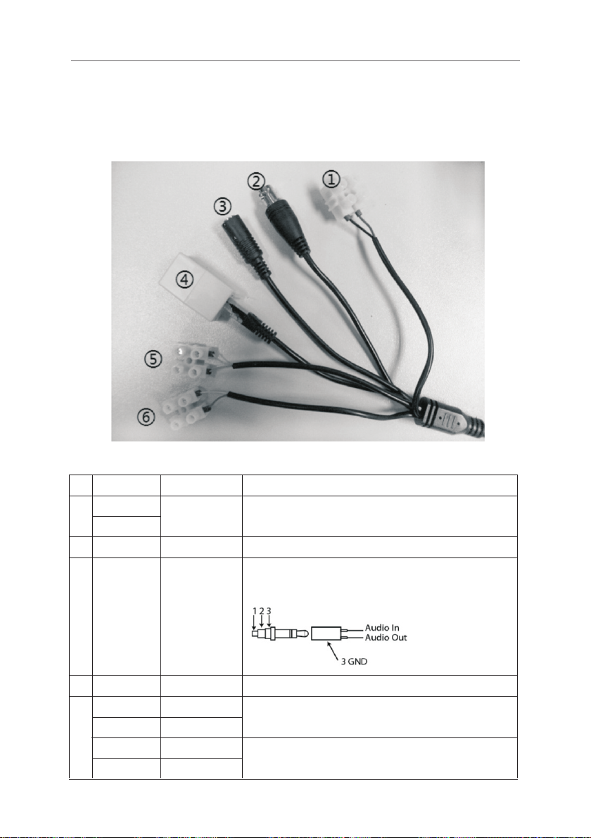
2.2 Connections
2.2.1 Cable Connections
Fig. 2.1 Connect ion C abl e
Mega Pi xel IP Spe ed Dome Came ra User ’s Ma nual
ID Cab le
Red
1
Bla ck
N/A Con nect to v ideo ca ble of mo nitor, s tanda rd BNC in terfa ce
2
3
N/A
N/A
4
Yellow
Gra y
5
Blu e
Pin k
Fun ction
AC2 4V Inpu t
Vid eo Out put
Aud io In/O utput
Net work in terfa ce
RS4 85+
RS4 85-
Ala rm in(DC1 2V)
Ala rm in GND
Ple ase ref er to the c amera p arame ter
3.5 mm int erfa ce, c onne ct to acoustic s device, such as spe aker etc
for audi o spe ech o utpu t(im pedan ce: >1 6Ω); conn ect t o audio input
dev ice, su ch as ton e arm(i mpeda nce: 1k Ω)
Con nect to E thern et devi ce, suc h as Ethe rnet ex chang er, HUB et c.
Con nect to R S-485 d evice , such as P an/Ti le, PT Z etc.
Con nect to a larm in put, 1 ch annel s ignal a larm(0~ DC12V)
Con necti on
4
Page 6

Mega Pi xel IP Spe ed Dome Came ra User ’s Ma nual
Chapter 3 Parameter setup
Some n etw ork p ara meters must be s etu p f irs tly after finishing i nst all ation, includes I P
address, subnet mask, port etc, can be s etu p thr oug h man y kin ds of w ays , see b elo w two kind s
for examples:
1. Setup paramet ers s uch a s IP address and P PPo E etc . thr oug h IE browser
2. Setup paramet ers t hro ugh a ppl ications on clien t’s s ide.
Please be confir m PC an d net wor k camera already be conn ect ed, a nd th e network camera ca n
be PING!
3.1 Setup parameter by IE browser
( Microsoft Internet Explorer only )
The default IP:1 92. 168 .0. 120, Default port : 300 01, u ser : adm in, password: adm in
Login net wor k camera by IE, input IP add res s, and wil l sh oot out log gin g in win dow, in put
username and pas swo rd, c lic k “ log in ” to enter IE client i nte rfa ce.
Function detai led g uid e ple ase r efer to “ Network Vid eo Ma nager System Manu al ”.
Impor tant Note: t o check d evice by IE, the prem ise is to s et browser s ecurity le vel,
open IE browser, enter “ too l / Inte rnet opt ion / secur ity / user- defined lev el ”, se t
secur ity level ”secu rit y leve l-low ”, or d ire ctly s et “ ActiveX , Widget and Ins ert ” to
open.
5
Page 7

A p p endix
Mega Pi xel IP Speed Dome Came ra User ’s Manual
Par amete r
Ima ge sens or
Hor izont al Reso lution
Min . illum ination
S/N R atio
AGC
BLC
Ele ctron ic Shut ter
Dec oder
Pan ning an gle
Til t angl e
Rot ary spe ed
Pre set
Dig ital Zo om
Foc al Leng th(mm)
Iri s
Foc us
Pro tecti on leve l
Vid eo Out put
Vid eo Com pression
Pic ture Re solut ion
Bit R ate
Mul ti-st ream
OSD
Aud io Out/ In
Aud io comp ressi on
Aud io Bit Ra te
Vid eo syn chron izati on
Bid irect ional Tal k
Mot ion det ection
hea rtbea t
Ala rm even ts
Use r Acc ess Li mit
Net work Tra nsmis sion
Web S erve r
Net work Pr otoc
Net work Po rt
I/O a larm in
ol
18X
1/3 ” Ex-vi ew 1.3M ega Pix el CCD
720 TVL(PA L) 810 TVL
0.1 Lux/F 1.2 , 0.02Lux/F1.2(S low sh utter )
>50 dB
Aut o
Aut o
Aut o
Int ernal
360 º Conti nuous r otation
0º~ 92º
Lev el 0.1~ 240º/ S, Verti cal 0.1~160º/S
00
2
18X
4.7-84.6mm
Aut o/Man ual
Aut o/Man ual
IP6 6, 24-h our, saf ety cov er,TVS1500W lightni ng pro of and su rge pro of
PAL/ NTSC , 1.0V p-p, 75 ohm loading, BNC conne ctor
H.2 64(IS O/IEC 1 4496- 10) bas eline profile to level 3 .1
PAL: 1280 x720p@25fps NTSC: SXGA (128 0x960p)@22.5fps.
CBR、V BR
Up to 2 c onfig urabl e frame rate/bit rate st ream s for pre view an d recor ding
PAL 128 0*720 a nd 640* 360 NT
Tim e,Da yDev ice nam e,Cha nnel name and user-def ined t ext
One a udio ou t , One aud io line i n
G72 3.1, 8K Hz, 16b its
6.3 Kbps
Sup port
Two wa y audio
Sup port
Sup port
I/O a nd moti on dete ction, Picture uploa d via em ail
Max o f 10 conc urrent connected use rs
Aut o adapt ive flo w control technology
Bui ld-in W eb Ser ver
IPv 4/v6, R TP/R TCP, TCP/UDP, HTT P, DHCP, DNS , FTP, DDN S, PPP OE, SM TP
RJ- 45,10 /100B ase-T
One Al arm in( DC5-1 2V)
NTS C)
SC 12 80*96 0 and 640 * 4 80
6
Page 8

Mega Pi xel IP Spe ed Dome Came ra User ’s Ma nual
PTZ C ontro l
SD Ca rd
Dep endab ility
Wor king Tem pera ture
Sto ring Temp erat ure
Pow er Cons umpti on
Pow er Supp ly
Sec urity
CMS C lient
SDK
RS4 85
Sup port on e up to 32G B Micro S D/HC Ca rd
Har dware w atch Do g
-10 -60℃ Hu midit y 10-90 %
-20 -70℃ Hu midit y 0-95%
Max . 13W
24VA C ±5% , 25 00mA
Mul ti-le vel use r and gro up mana gemen t, user a ccess c ontro l
Sup plied C MS clie nt suit able fo r IP prod ucts ( Came ra/NV S/PTZ e tc)
Hig hly doc ument ed SDK fo r be-sp oke cus tom req uirem ents an d appli catio n
dev elopm ent
Chapter 4 System Installation
4.1 Installation
1) Dimension
ø 0
20
Ind oor
31 5
33 8
ø238
Out door
7
Figure 1
Page 9

2) Installation Style
a Wal l Insta llation
Mega Pi xel IP Spe ed Dome Came ra User ’s Ma nual
Figure 2
27 8
b Penda nt Installati on
63
20 0
62 0
Figure 3
c Ceili ng Mounting
36 8
ø155
ø237
Out door Ind oor
27 8
63
20 0
60 5
ø155
ø237
Out door
80
34 3
ø
9
8
1
ø
ø155
ø200
ø155
ø200
Ind oor Dem ensio n
this hatch aim at the side where
cable comes out
9
ø
103
140
Dem ensio n
104
ø
8
.5
104
122
160
0
2
1
ø
Figure4
ø200
80
30 9
the size of installation hole at
Dome’s pedestal
8
4- 7
ø
Page 10

Mega Pi xel IP Spe ed Dome Came ra User ’s Ma nual
d Ceili ng mo unt
Dimen sion
Embed into a cutou t wit h a dia met er slightly
Figure5
larger than 236m m (9. 25” ).
4.2 Installation Steps
Taking wall -in stallati on st yle as examp le:
1. Unpacking the c art on an d car efu lly take out the dome c ame ra an d its a ttachments.
2. According to the s ize o f Dom e, dr ill the installation h ole i n the w all a nd fixed expander bolt s.
(Also can drill ho le ac cor din g to fixed hole of bracket )
3. Rotate the dome c ove r CCW ( cou nterclockwise) and t o rem ove .
4. Rotate the dome c ove r CW (c loc kwise) to install D ome .
5. Fix the bracket o n the m ain b ody o f dome, rotate the Do me CW ( clo ckw ise ), and keep the
bracket hole and t he mo unt ing f lange in line. Tighten th e thr ee sc rew s.
6.Fetch the sign al ca ble , vid eo cable and power wires f rom b rac ket . Fix the cover plate , tig hte n
the knurled-sc rew.
7.Fix the assemb led D ome o n the w all and tighten the 4PCS o f sup pli ed sc rews.
Figure 6
Dom e Main Bo dy
Cou nter cl ockwi se rota te the
tra nspar ent cov er
swi tch
but ton
9
Page 11

Mega Pi xel IP Spe ed Dome Came ra User ’s Ma nual
天花板
固定座
1)将固定座安装在天花板上
2)将球机主体对准固定座上的3根导柱向上安装
球机主体
此两箭头对准
3)将球机主体逆时针旋转安装到位
4)将止退螺丝旋到底,完成安装
止退螺丝
O
P
E
N
C
L
O
S
E
8.Instructio n of su rfa ce in stallation:
According to t he s ize of Dome's fixed boa rd, dri ll t he installa tio n ho le o n th e ceiling an d fi xed
expander bolt s (A lso can dri ll h ole acc ording to fixed hol e of fix ed b oar d. F ix t he f ixed board,
fix the m ain b ody of dome on f ixe d boa rd along the g uide pol e, ro tat e the Dome anticlockw ise ,
and tighten the sc rew s.
Figure 7
Figure 8
Ceili ng
1) Fix pedestal on ceiling
3) CCW rotate main body at correct location
Regulate arrowhead
Pedes tal
2) Fix the mai n body on pendes tal along 3 guide pole s
Knurled screw
4) Tight en the knurled screw
10
Main Body
Page 12

Mega Pi xel IP Spe ed Dome Came ra User ’s Ma nual
4.3 Disassembly and installation of Main Body
1.Quick disa sse mbl y des ign , be easy to maintain a nd ch ang e the m ain b ody.
2.Tu rn vitreous cover on its a xis i n CCW ( cou nter clockwise) d ire cti on an d sep arate it down.
3.Then loose n knu rle d-s cre w as shown bellow. Hol d the d rie r she lf, l ook up the dome, revo lve
main body CCW (cou nte r clo ckw ise) and fetch it out .
4.The steps of i nst all ati on ar e reverse to those of d isa sse mbl y.
Counter clockwise
rotate the
transparent cove
Safety bel
Dome Main Body
Figure 9
4.4 Dome Configuration.
Wall Mountin g bracket
Ceilin g Mounting Fla nge
Outdoo r Cover
Up-she ll
Down-s hell
Main Bod y
Vit reous Cover
Figure 10
11
Page 13

Mega Pi xel IP Spe ed Dome Came ra User ’s Ma nual
Ap pendix A: 24VAC Wire Di ameter a nd Tr ansmi ss ion Dist ance Co mp ariso n
Ch art W hi le th e wire diame te r det er minat e and 2 4VAC l oss rat e und er 10%, the
lo ngest tra nsmissi on distan ce is recom mended as f ollowin g ch art.
Wire diam eter (m m)
Tra nsm ission
Distance
Power(VA)
10
20
30
40
50
60
70
80
90
100
110
120
130
140
150
160
170
180
190
200
feet(m)
0.8000
283(86)
141(42)
94 (28)
70 (21)
56 (17)
47 (14)
40 (12)
35 (10)
31 (9)
28 (8)
25 (7)
23 (7)
21 (6)
20 (6)
18 (5)
17 (5)
16 (4)
15 (4)
14 (4)
14 (4)
1.000
451(137)
225(68)
150(45)
112(34)
90(27)
75(22)
64(19)
56(17)
50(15)
45(13)
41(12)
37(11)
34(10)
32(9)
30(9)
28(8)
26(7)
25(7)
23(7)
22(6)
1.250
716(218)
358(109)
238(72)
179(54)
143(43)
119(36)
102(31)
89(27)
79(24)
71(21)
65(19)
59(17)
55(16)
51(15)
47(14)
44(13)
42(12)
39(11)
37(11)
35(10)
2.000
1811(551)
905(275)
603(183)
452(137)
362(110)
301(91)
258(78)
226(68)
201(61)
181(55)
164(49)
150(45)
139(42)
129(39)
120(36)
113(34)
106(32)
100(30)
95(28)
90(27)
12
Page 14

Mega Pi xel IP Spe ed Dome Came ra User ’s Ma nual
Appen dix B: Wire Gauge C onversion Cha rt
Bare wire diamet er
metric size(mm)
0.050
0.060
0.070
0.080
0.090
0.100
0.110
0.130
0.140
0.160
0.180
0.200
0.230
0.250
0.290
0.330
0.350
0.400
0.450
0.560
0.600
0.710
0.750
0.800
0.900
1.000
1.250
1.500
2.000
2.500
3.000
AWG
(Approximate )
43
42
41
40
39
38
37
36
35
34
33
32
31
30
29
28
27
26
25
24
23
22
21
20
19
18
16
15
12
SWG
(Approximate )
47
46
45
44
43
42
41
39
37
35
33
31
30
29
28
24
23
22
21
20
19
18
14
Bare wire cross
sectional area(m m )
0.00196
0.00283
0.00385
0.00503
0.00636
0.00785
0.00950
0.01327
0.01539
0.02011
0.02545
0.03142
0.04115
0.04909
0.06605
0.08553
0.09621
0.1237
0.1602
0.2463
0.2827
0.3958
0.4417
0.5027
0.6362
0.7854
1.2266
1.7665
3.1420
4.9080
7.0683
2
13
Page 15

Mega Pi xel IP Spe ed Dome Came ra User ’s Ma nual
Appen dix C: Lightnin g Proof and Surge S ignal Proo f
The pro duc t ad opt s TVS lig htning proo f te chn ology to pre ven t from da mag e by lightning s tri ke
below 150 0 W and impulse signals such as surg e; but it is al so nece ssa ry to abide by the
following prec aut ion s to en sur e electrical safe ty ba sed o n pra ctical circumstanc es:
Keep the comm uni cat ion cab les at leas t 50 meters away f rom hig h vol tag e equipment or
cables.
Make outdoor cab le la yin g-o ut un der eaves as possib le as y ou ca n.
In open area shi eld ca ble s in steel tube and con duc t a sin gle po int ground to the tu be.
Tro lle y wire is forbidden i n suc h cir cum sta nces.
In str ong thunderstorm or h igh far adi c z one (su ch as high vo lta ge tran sfo rme r substation) ,
extra strong lig htn ing p roo f equ ipment must be inst all ed.
Take t he building lig htn ing p roo f requirements into acc oun t to d esi gn the li ght ning pro of and
grounding of o utd oor equi pme nt and c able l ayi ng-out in accorda nce with t he nat ion al and
industrial sta nda rds .
The sys tem mu st be gro unded with equ al pot ent ials. The ear th gro und connection must
satisfy the anti-int erf ere nce and electrical safety requi rem ent s an d mu st n ot b e sh ort
connected w ith hig h voltage e lec tri cit y net. When the sys tem is grounded separat ely, the
resistance of dow n conduct or should b e ≤ 4Ω and the sectional a rea of down c ond uct or
should be ≤ 2 5mm (refer to Figur e E.1 ).
2
14
Page 16

GUARANTEE
For any camera produced by VEILUX, we promise two years to repair your camera while
it is still under warrenty.
During Guarantee period, we supply free service except following situations:
•User does not operate as manual book requires
•User un-install the whole product by themselves
•Lightning or Act of God
•Physical Damage
•Power Surge
•Used Incorrect Housing for Install
If there are additional agreements between VEILUX and buyer, then agreements shall
be strictly done
STATEMENT
bility to inform user
This manual book belongs to VEILUX rights, without permits or any book inform, any
company or
private copy of whole or part of the book shall be prohibited.
The Art of Surveillance
802 Greenview Dr., Suite 200
Grand Prairie, Texas 75070
Toll Free: 1-800-510-6528
Tel: 214-635-4855
Fax: 214-988-2858
Website: www.veilux.net
Email: Sales@veilux.net
®
 Loading...