

Page 1
YHQ18 Explosionproof Camera Manual Book
Ver: 0.1
Ex Mark: II 2 GD Ex d IIC T6 Gb, Ta : -15°C to +60°C
Ex t IIIC T80°C Db
Certificate: Nemko 11ATEX1022
Veilux User Manual SVEX-Q18 Intelligence Camera Set
Page 2
SVEX-Q18 Explosion proof Camera Manual
Book
Please carefully read the Manual Book before your operation
1. Installation
„
Please install under required environment
„
Ensure stable and reliable mounting in case camera be damaged
„
Ensure supply power same as nameplate marked before equipment being powered
„
Do not open the pan/tilt and enclosure under humid atmosphere, otherwise video picture will be influenced
because of enclosure good sealing, humidity could not go outside.
„
Please connect cable correctly
„
The product is for ceiling mounting only.
2. Maintenance
„
Please shut off before maintenance and repair
„
Pay attention to the flameproof joint while disassembly and assembly
Page 3
SVEX-Q18 Explosion proof Camera Manual
Book
3
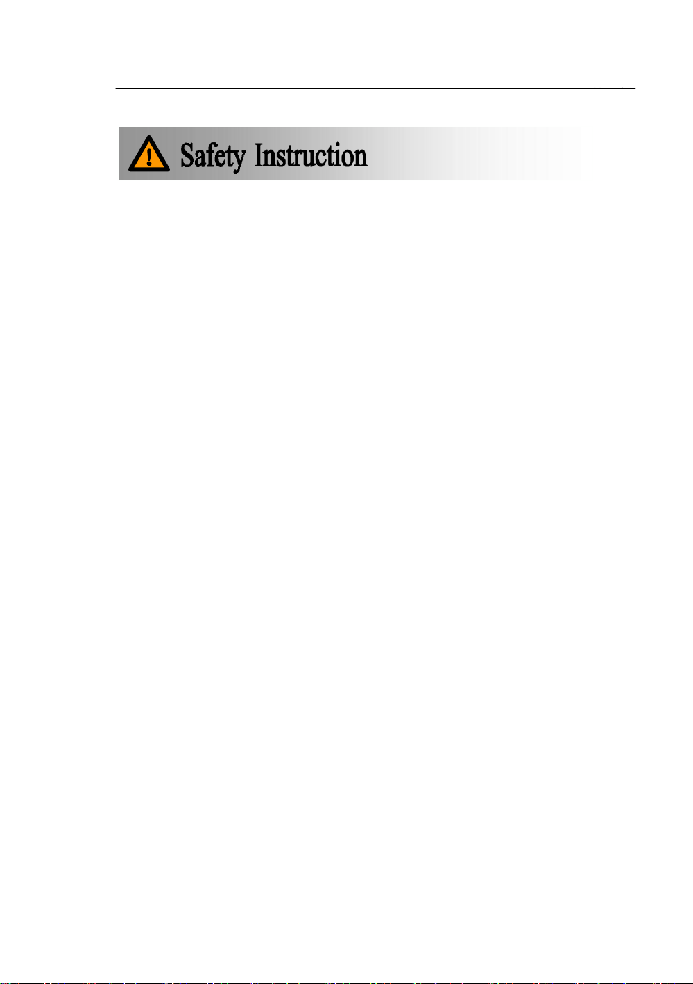
Most Suitable Position for Movement
Choose the most suitable position when moving the
equipment.
Page 4
SVEX-Q18 Explosion proof Camera Manual
Book
4
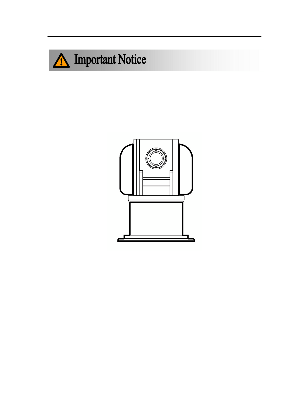
Move the camera like
this
Move the camera like
this
No
hammar
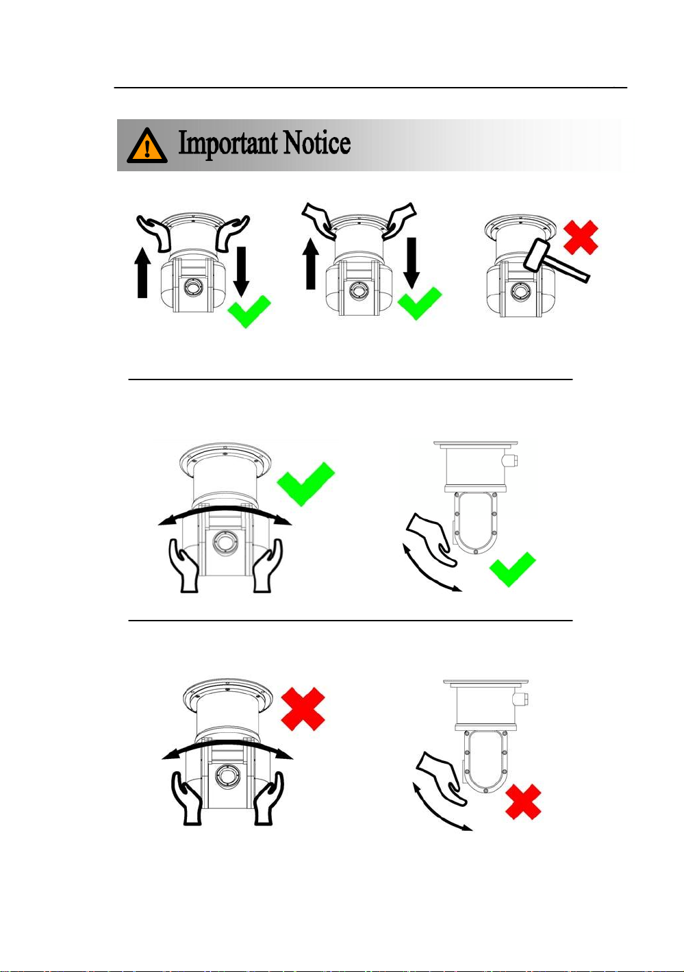
The camera can be rotated when power
off
Do not turn the camera when power on
Page 5
5
YHQ18 Explosionproof Camera Manual Book
Ver: 0.1
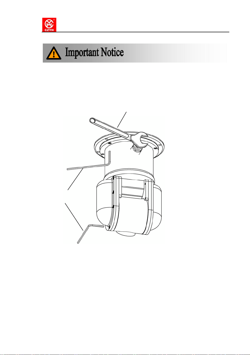
Tighten the top panel
camera setting is
Pay attention to the
when
finished.
o-ring
Tighten this screw after the cable
is connected
Page 6

6
SVEX-Q18 Explosion proof Camera Manual
Book
CONTENT
1. BRIEF ................................................................................................. ...............................................7
2. TECHNICAL .....................................................................................................................................7
2.1 Type Code ............................................................. .................................................................7
2.2 Certificate............... ......................................... .......................................................................7
2.3 Electric Data............................................................................................................. ..............8
2.4 Camera Data...........................................................................................................................8
2.5 Mechanical .............................................................................................................................9
2.6 Environmental .......................................................................................... ..............................9
2.7 Dimension ..................................... .........................................................................................9
2.8 Mounting Size ......................................................................................................................10
3. INSTALLATION..............................................................................................................................10
3.1 Caution ........................................................................ .........................................................10
3.2 Ceiling Mount .................................................................................................................. ....10
3.3 Cable Working .....................................................................................................................11
3.3.1 Ex Cable Use ..................................................................................11
3.3.2 Armored Cable Use........................................................................11
4. CONNECTION, SETTING & APPLICATION .............................................................................13
4.1 System Diagram ...................................................................................................................13
4.1.1 Connecting Diagram ......................................................................13
4.1.2 Cable Definition ........................................................... ...................13
4.1.3 Power and Video Cable Connection................................ ............14
4.1.4 Control Signal Connection ............................................................14
4.2 Setting ......................................................................... .........................................................15
4.2.1 Set Method ......................................................................................15
4.2.2 Camera Address Set............................................................ ..........16
4.2.3 Communication Protocol Set ........................................................16
4.2.4 Baud Rate Setting ..........................................................................16
4.2.5 Remote Control Setting .................................................................17
5. OSD MENU FUNCTION ...............................................................................................................17
6. FLAMEPROOF STRUCTURE .............................................. .......................................................17
7. TROUBLE SHOOTING .................................................................................................................18
8. SHIPPING AND STORGE........................................................................................................... .18
9. QUALITY GUARANTEE ...............................................................................................................19
10. COMPANY COMITTMENT ....................................................................................................... .19
Page 7

7
SVEX-Q18 Explosion proof Camera Manual
Book
1. BRIEF
This SVEXQ18 EXPLOSIONPROOF PAN TILT CAMERA( therefore as SVEX-Q18)as a new
monitoring equipment adopts advanced production techniques and matured quality management system to make
its quality, performance and appearance a leading position in explosion proof monitoring products. It can be
used in flammable and explosive environment to realize monitoring purpose.
Strictly according to European Directive EC/94/9 and EN 60079-0: 2009, EN 60079-1: 2007, EN60079-31: 2009,
Standards of GB3836.1-2000 GB3836.1—2000 Electrical apparatus for explosive atmosphere: General
requirements, GB3836.2-2000 Electrical apparatus for explosive atmosphere: Flameproof„d‟ and
GB12476.1-2000 Electrical apparatus for explosive dust: Using enclosure and limiting surface temperature for
protecting electrical apparatus Chapter 1: Technical requirements, this camera owns advantage of small volume,
light weight and easy installation features and could be used in petroleum, chemical industry, jetty, port, mine,
space, army and foodstuff area.
YHQ18 with high performance color integrated camera, 23X optical lens, 10X digital zoom could adjust pan tilt
speed according to lens location to keep a clear quality image. It owns low lux technique and color B/W auto
change, digital picture up/down and freeze function.
YHQ18 with multiple protocols to respond different control directives, its body moves 360° pan turning
Continuously and tilt -90°~-+30°, with 64 presets to work in any complicated atmosphere.
2. TECHNICAL
2.1 Type Code
S V EX
2.2 Certificate
Ex Mark II 2 GD Ex d IIC T6 Gb, Ta : -15°C to +60°C
Ex t IIIC T80°C Db
Q
18 E x
EX Mark
Design No.
Dome Camera
Veilux
Page 8

8
SVEX-Q18 Explosion proof Camera Manual
Book
Ex Certificate Nemko 11ATEX1022
2.3 Electric Data
Input voltage 110~240VAC, 50/60Hz
Working current ≤500mA
Power consumption <50W
Communication RS-485
Communication speed multiple, could be set
Communication protocol multiple, could be set
Address code 256
Preset position 128
Preset Accuracy ≤0.1°
Electric connection 6-core cable for control, Power and video
2.4 Camera Data
Brand HITACHI
Type VK-S858EN
Mode PAL
Scan Line scan
CCD 1/4″SONY CCD
Line Scan 15.625KHz
Site scan 50Hz
Pixel 470,000/795(H) x 596(V)
Lens High performance /23X optic zoom / auto focus / F1.6, f=3.6~82.8mm
10X digital zoom total 230X
Min focus 0.01m(tele)/ 1.0m(far)
View angle 54°(wide)/ 2.5°(far)
Signal process No. 6 DSP
Low Lux 0.1Lux(color)/ 0.02Lux(black)
TVL 480(color)/ 600(black/white)
SNR > 50dB
Page 9

9
SVEX-Q18 Explosion proof Camera Manual
Book
Video output BNC joint / 1.0±0.2Vp-p / 75Ω
2.5 Mechanical
Material Stainless 304
IP level IP67
Pan 0~360° continuously
Tilt -90°~-+30°
Pan speed 0.1°/S ~60°/S
Tilt speed 0.1°/S ~60°/S
Unit/ Ship weight 22Kg / 25Kg
Mounting ceiling
2.6 Environmental
Air pressure 86~106KPa
Environment temperature -15℃~+50℃
Relative humidity U95%RH (+25℃)
2.7 Dimension
P1. SVEX-Q18 out dimension
Page 10

10
SVEX-Q18 Explosion proof Camera Manual
Book
2.8 Mounting Size
P2. Camera bottom fix hole on diameter 216mm round
3. INSTALLATION
3.1 Caution
Please carefully check before installation
a. If there is ex-marking license
b. The ex-marking satisfy environment use
c. All ex-proof and flameproof parts are complete enough for structure
d. Inside and outside earthlings are ready
Stop immediately while there is any unconformity
3.2 Ceiling Mount
Mount hole for fix
Cable out
Camera Glass
Please refer to chapter 4.2 for the setting of SVEX -Q18 before installation. For the bottom fix hole
installation, please refer to P2.
P3. Ceiling mount
Page 11

11
SVEX-Q18 Explosion proof Camera Manual
Book
P4. Tilt rotation angle
3.3 Cable Working
3.3.1 Ex Cable Use
a. As P6, open the tighten screw on the base of camera, open ex cable screw joint for future use.
Ex cable
Gasket
Cable outlet
b. As P6 firstly tight screw joint and then tight ex cable
Screw Joint Gasket Cable out
P5.
Cable outlet
Ex cable
P6.
3.3.2 Armored Cable Use
a. as Picture 8, remove proper length cable protection cover and cut off not used part.
Page 12

12
SVEX-Q18 Explosion proof Camera Manual
Book
Armored cable
Rubber
Protection Cover
Cable inner layer
Sealing Loop
Bushing
Bushing
Joint
Steel belt Cable core wire
Nut
Gasket Taper Volt
P7.
b. as Picture 8, install Ex-proof Gland to Armored Cable
Armored cable Out Finished Gland Cable Inner Layer
Screw
c. armored cable with ex gland could be connected with any ex equipment‟s.
P8.
Ex-proof Gland Parts
Thread
Page 13

SVEX-Q18 Explosion proof Camera Manual
Book
14
Composite Cable
Name
Power
Control(shielded)
Video
4. CONNECTION, SETTING & APPLICATION
4.1 System Diagram
4.1.1 Connecting Diagram
Video signals can be connected with different equipment, such as LCD monitors, DVRs, video server or
matrix. The signals can be also distributed or gained by video distributors as well.
All equipment‟s can control the camera with suitable communication way and protocols. Code adapter
(protocol converter) is used for some matrix and RS232-RS485 converter is necessary for some DVR system.
P9
4.1.2 Cable Definition
While camera leaves factory, we supply a Composite Cable* with camera, the cable goes out from Camera
bottom with length at least 2 meters. So while connection the system, just connect the cable with Junction Box.
(*Composite Cable: A special cable, one Composite Cable includes one group power, one group control and one
group video, it is generally used in Industry CCTV system.)
Table 1: Cable Definition
Page 14

SVEX-Q18 Explosion proof Camera Manual
Book
15
Function
Live
wire
Neutral
wire
Earth wire
RS485-A
RS485-B
Standard Video Cable
Color
Brown
Grey
Yellow/Green
Red
Blue
4.1.3 Power and Video Cable Connection
A junction box shall be used with SVEX-Q18 as Picture, and refer to Table 1 to connect cable of power
and video inside Junction Box. Remember to use ex cable for power cable out of Junction Box.
4.1.4 Control Signal Connection
While connecting Control Source and Cameras as below, please use Control Code Distributor. Besides
adding a 12Ohm Terminal Resistor between Terminal A and B (as T6 Communication Board, Jumper JMP2
under off position
Camera
Camera
Camera
A B
Gnd
A B
Gnd
A B
Gnd
A B
Gnd
120Ω
120Ω
120Ω
A B
Gnd
A B
Gnd
A B
Gnd
A B
Gnd
Control
code
distribut
or
A B
Gnd
A B
Gnd
Camera
120Ω
P10. Star Connection
While connecting Control Source and Camera as below, please just add one 12Ohm Terminal Resistor
between Terminal A and B( JMP2 on). And pay attention that the distance between junction box and camera
shall not beyond 7mters
Camera
A B Gnd
A B Gnd
Camera
A B Gnd
120Ω
Camera
A B Gnd
Control
P11. “Chrysanthemum” Connection
Control
signal
source
Page 15

SVEX-Q18 Explosion proof Camera Manual
Book
16
4.2 Setting
4.2.1 Set Method
After opening the left side panel, the dip switch can be seen. The customer needs to set the protocol,
address and baud rate. See the below chapter for reference.
When power is on, the camera version, protocol, baud rate and address of current camera are shown.
P12. Set Method
VERSION:1.0
PROTOCOL:PELCO-P
BAUD:4800
CAMERA ID:001
K2 K1
K3
K4 K5
P13. Setting board
To set address and baud
rate here in camera
Pay attention of the F.P
Page 16

SVEX-Q18 Explosion proof Camera Manual
Book
17
Dip Switch
K3
K2
K1
Address
0 0 2
Dip Switch
K3
K2
K1
Address
1 3 8
Dip Switch
Protocol
1
PELCO-P
2
PELCO-D
Dip Switch
Baud Rate
0
Remote Control
1
1200 2 2400 3 4800 4 9600
5
19200
4.2.2 Camera Address Set
Decimal system is used for camera address, K1、K2、K3 dip switches are for address setting. K1 stands for
the unit digit, K2 is for tens digit and K3 for hundreds digit. Other K4 is for baud rate and K5 for control protocol.
e.g if the camera address is No.2, the K1 needs be 1 and K2, K3 should be 0, see below table:
If the camera address is No.138, the K1 needs be 8, K2 is 3 and K3 should be 1, see below table:
4.2.3 Communication Protocol Set
Check the protocols in the control system and then set K5 as below table. The new setting will work after
power on again.
Table 2: Protocol setting (K5)
4.2.4 Baud Rate Setting
Set baud rate with K4 as below table. The new setting will work after power on again.
Table 3: Protocol setting (K4)
Page 17

SVEX-Q18 Explosion proof Camera Manual
Book
18
4.2.5 Remote Control Setting
When K4 is “0”, camera address, control protocol and baud rate can be set with OSD Menu (the default
baud rate is shown on the display when power is on). At this time, the setting of K1, K2, K3 and K5 won‟t work.
Setting process is as below: Go to preset 95, press MAIN MENU CONTROL RS485.
5. OSD MENU FUNCTION
OSD MENU is available for this camera. You can enter OSD like this: when camera power is on, go to No.95
preset and the main menu will be shown. Then the “UP”, ”DOWN”, ”LEFT”, ”RIGHT”, “IRIS OPEN” and ”CLOSE”
in the control part will turn into the menu control key, the other keys of control part will not work. When :<>” is
shown, it means there is a slave menu. “UP” and ”DOWN” can choose the menu; while ”LEFT” and “RIGHT” can
change the specification. “OPEN” means OK and it can go into the slave menu as well. When the menu item is
used, it will glitter.
When system is in scan mode, “RETURN: CLOSE” will be shown in the lower left corner of display. You can
quit with “IRIS CLOSE” and then control the camera.
6. FLAMEPROOF STRUCTURE
z
Completely consider the explosive air getting into ex-proof structure, which may lead to explosion because
of some reason and to confirm and ensure camera explosion proof performance based on its structure gap,
length and max temperature it will get to.
z
Enclosure shall burden water pressure testing for 1.5Mpa for 10~12 seconds without leakage as pass,
which is ordered in GB3836.2-2000.
z
Camera surface temperature max shall not over 80℃ while it is working.
z
Window glass adopts steel glass to burden Impact and Heat change testing.
z
Enclosure protection to IP67
„
Cable for Camera uses inlaid device to tighten its screw and nut and make cable tight and no move.
Page 18

SVEX-Q18 Explosion proof Camera Manual
Book
19
Problems
Reason
Method
No image
Power off
Make sure the power is ok
Video cable not
good connection
Check the Video Cable
Sometime no image
Video cable not
good connection
Check the Video Cable
Control error
Not good connection
of Signal cable
Check Signal Cable is correct connection
Too long communication
distance make signal
loose
Add repeaters to make communication
distance longer
Signal reflect
Short connect the farthest camera decoder
board‟120 and add 120Ω resistance to remove
reflect
Not correct Address
To re-set refer to Manual book
Not correct Protocol
Not correct Baud rate
F.P
7. TROUBLE SHOOTING
P14. Flameproof point location
Table 4. Trouble shooting
F.P
F.P
8. SHIPPING AND STORGE
After package, without rain or snow fall directly to product, shipment could do by air or sea and store for one
year under the environment of 0℃~+40℃, humidity >90%
Page 19

SVEX-Q18 Explosion proof Camera Manual
Book
20
9. QUALITY GUARANTEE
For any camera produced by Veilux, we promise half-year to change and one year to repair. During
Guarantee period, we supply free service except following situations:
z
User does not operate as manual book requires
z
User un-install the whole product by themselves
z
Lightning or Act of God
If there are additional agreements between Veilux and buyer, then agreements shall be strictly done
10. COMPANY COMITTMENT
„
Veilux owns the final design changing and final specification rights and no responsibility to inform
user
„
This manual book belongs to Veilux rights, without permits or any book inform, any company or
private copy of whole or part of the book shall be prohibited.
802 GREENVIEW DR STE 200
GRAND PRAIRIE, TX. 75050
Website: www.veilux.net
E-mail: Sales@veilux.net
Phone # 1-800-510-6528
 Loading...