

Page 1

PROCESS AUTOMATION
MANUAL
WHA-GW-*
WIRELESSHART GATEWAY
®
Page 2

WHA-GW-*
With regard to the supply of products, the current issue of the following document is ap-
plicable: The General Terms of Delivery for Products and Services of the Electrical In-
dustry, published by the Central Association of the Electrical Industry (Zentralverband
Elektrotechnik und Elektroindustrie (ZVEI) e.V.) in its most recent version as well as the
supplementary clause: "Expanded reservation of proprietorship"
Page 3

WHA-GW-*
1 Safety................................................................................................. 6
1.1 Validity....................................................................................................................................6
1.2 Symbols used ........................................................................................................................6
1.3 Target Group/Staff.................................................................................................................7
1.4 Reference to further documentation....................................................................................7
1.5 Declaration of Conformity.....................................................................................................7
1.6 Marking ...................................................................................................................................7
1.7 Intended Use ..........................................................................................................................8
1.8 Mounting and Installation .....................................................................................................8
1.9 Operation, Maintenance, Repair...........................................................................................9
1.10 Delivery, Transport, Disposal................................................................................................9
2 Product Specifications .................................................................. 10
2.1 Introduction..........................................................................................................................10
2.2 Functional Overview............................................................................................................11
2.2.1 Network Management ...........................................................................................................12
2.2.2 Security Management............................................................................................................13
2.2.3 Virtual Remote I/O system..................................................................................................... 13
2.2.4 Gateway Cache Management ...............................................................................................15
2.3 Scope of Delivery.................................................................................................................16
2.4 Design...................................................................................................................................16
3 Installation ...................................................................................... 18
3.1 Mounting Considerations ...................................................................................................18
3.1.1 Positioning the Gateway........................................................................................................18
3.1.2 Antenna Characteristics......................................................................................................... 18
3.1.3 Examples for Good and Poor Positioning..............................................................................20
3.2 Mounting the Gateway.........................................................................................................22
3.3 Connecting to Ethernet.......................................................................................................23
3.4 Connecting to RS-485 .........................................................................................................28
3.5 Connecting the Antenna .....................................................................................................30
3.6 Connecting to Power Supply and Grounding ...................................................................31
4 Commissioning .............................................................................. 33
4.1 Important Steps to Getting Started ....................................................................................33
4.2 DTM Software.......................................................................................................................33
4.2.1 Downloading the required software .......................................................................................33
4.2.2 Installing the Required Software............................................................................................34
4.2.3 Updating the DTM catalog .....................................................................................................35
4.3 Connecting via RS485.........................................................................................................36
4.4 Connecting via Ethernet .....................................................................................................37
3
Page 4

WHA-GW-*
4.5 Creating a new PACTware Project ....................................................................................38
4.5.1 Creating a new project...........................................................................................................38
4.5.2 Adding the Communication DTM...........................................................................................38
4.5.3 Adding Device DTM...............................................................................................................43
5 Configuration ..................................................................................45
5.1 Configuration via DTM or Web Interface ...........................................................................45
5.2 Online and offline parameterization (DTM) .......................................................................46
5.3 Identification Parameters....................................................................................................48
5.4 Wireless Communication Parameters................................................................................49
5.4.1 Setup .....................................................................................................................................49
5.4.2 Instrument List .......................................................................................................................51
5.4.3 Burst Lists ..............................................................................................................................54
5.5 Wired Communication Parameters....................................................................................56
5.5.1 Interfaces > Serial..................................................................................................................56
5.5.2 Interfaces > Ethernet .............................................................................................................57
5.5.3 Protocols > HART ..................................................................................................................59
5.5.4 Protocols > Modbus...............................................................................................................60
5.6 Network Explorer Tables.....................................................................................................62
6 Operation .........................................................................................64
6.1 Controls and Indicators ......................................................................................................64
6.1.1 LEDs ......................................................................................................................................65
6.1.2 Buttons and DIP switches......................................................................................................66
6.2 Diagnosis..............................................................................................................................69
6.2.1 Identification...........................................................................................................................69
6.2.2 Wireless Communication .......................................................................................................70
6.2.3 Wired Communication ...........................................................................................................71
6.3 Additional DTM Functions ..................................................................................................74
6.3.1 Reset .....................................................................................................................................75
6.3.2 Self Test.................................................................................................................................75
6.3.3 Set DTM address...................................................................................................................76
6.3.4 Set device address ................................................................................................................77
6.3.5 List Editor...............................................................................................................................78
6.3.6 About .....................................................................................................................................79
6.3.7 Change Password .................................................................................................................79
6.3.8 Firmware Upgrade .................................................................................................................80
6.4 Network Enhancement ........................................................................................................81
6.5 Modbus Mapping .................................................................................................................83
6.5.1 Overview................................................................................................................................83
6.5.2 Modbus Mapping Description ................................................................................................84
7 Maintenance and repair..................................................................87
7.1 WHA-GW* .............................................................................................................................87
4
Page 5

WHA-GW-*
8 Troubleshooting ............................................................................. 88
8.1 Faults indicated by Gateway LEDs ....................................................................................88
8.2 Wired Communication Faults.............................................................................................88
8.3 Wireless Communication Faults.........................................................................................89
9 Technical specifications................................................................ 90
9.1 WHA-GW...............................................................................................................................90
9.2 Telecommunication Compliance........................................................................................92
10 Appendix A ..................................................................................... 93
10.1 Supported Commands ........................................................................................................93
10.1.1 Universal Commands ............................................................................................................93
10.1.2 Common Practice Commands ...............................................................................................94
10.1.3 Wireless Commands..............................................................................................................94
10.1.4 Device Commands ................................................................................................................95
10.2 Software License .................................................................................................................95
5
Page 6
WHA-GW-*
Safety
1Safety
1.1 Validity
The chapter “Safety” is valid as instruction manual.
Specific process and instructions in this document require special precautions to guarantee
the safety of personnel.
1.2 Symbols used
This document contains information that you must read for your own personal safety and to
avoid property damage. The warning signs are displayed in descending order depending
on the hazard category, as follows:
Safety-relevant symbols
Danger!
This symbol indicates a warning about a possible danger.
In case of ignoring the consequences may range from personal injury to death.
Warning!
This symbol indicates a warning about a possible fault or danger.
In case of ignoring the consequences may cause personal injury or heaviest property
damage.
Caution!
This symbol warns of a possible fault.
In case of ignoring the devices and any connected facilities or systems may be interrupted
or fail completely.
Informative symbols
Note!
This symbol brings important information to your attention.
Action
This symbol marks an acting paragraph.
221981 2011-07
6
Page 7

WHA-GW-*
Safety
1.3 Target Group/Staff
The plant owner is responsible for its planning, installation, commissioning, operation,
maintenance and disassembly.
Mounting, commissioning, operation, maintenance and dismounting of any devices may
only be carried out by trained, qualified personnel. The instruction manual must be read
and understood.
1.4 Reference to further documentation
Laws, standards, or directives applicable to the intended use must be observed. In relation
to hazardous areas, Directive 1999/92/EC must be observed.
The corresponding data sheets, declarations of conformity, EC Type-examination
certificates, certificates and Control Drawings if applicable (see data sheet) are an integral
part of this document. You can find this information under www.pepperl-fuchs.com.
Due to constant revisions, documentation is subject to permanent change. Please refer
only to the most up-to-date version, which can be found under www.pepperl-fuchs.com.
1.5 Declaration of Conformity
All products were developed and manufactured under observance of the applicable
European standards and guidelines.
Note!
A Declaration of Conformity can be requested from the manufacturer.
The product manufacturer, Pepperl+Fuchs GmbH, 68307 Mannheim, has a certified quality
assurance system that conforms to ISO 9001.
ISO9001
1. 6 M a r k i n g
WirelessHART® Gateway
Pepperl+Fuchs GmbH
Lilienthalstraße 200
68307 Mannheim, Germany
WHA-GW-*
PF 09 CERT 1469 X
II 3 G Ex nA II T4
221981 2011-07
7
Page 8
WHA-GW-*
Safety
1.7 Intended Use
The devices are only approved for appropriate and intended use. Ignoring these
instructions will void any warranty and absolve the manufacturer from any liability.
The approved usage of the connected device(s) and gateway can be taken from the
corresponding parts of their instruction manual.
The device is an intelligent WirelessHART device designed for the transmission of
measured values from connected C&I or HART devices.
The device must only be operated in the ambient temperature range and at the relative
humidity (non-condensing) specified.
Protection of the operating personnel and the overall system is not ensured if the product is
not being used according to its intended purpose.
1.8 Mounting and Installation
Prior to mounting, installation, and commissioning of the device you should make yourself
familiar with the device and carefully read the instruction manual.
The device must not be installed at locations where corrosive vapors may be present.
The devices are designed for use in pollution degree 2 and overvoltage category II as per
IEC/EN 60664-1.
If used in areas with higher pollution degree, the devices need to be protected accordingly.
Pay attention to avoid electrostatic discharges while operating the installed device. Avoid
electrostatic charge.
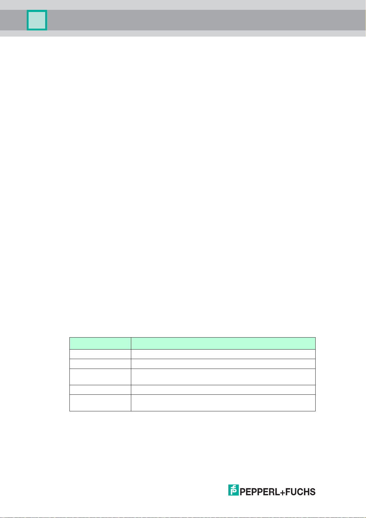
The usage of 2400 MHz equipment is bound to local restrictions. Ensure that restrictions
allow usage of this product before commissioning.
Country Guideline
Bulgaria General authorization required for outdoor use and public service.
Italy If used outside of own premises, general authorization is required.
Norway May be restricted in the geographical area within a radius of 20 km
from the center of Ny-Alesund.
Rumania Use on a secondary basis. Individual license required.
Latvia The outdoor usage of the 2.4 GHz band requires an authorization
from the Electronic Communications Office.
Only use antennas that are specified in the data sheet.
If devices have already been operated in general electrical systems, they may
subsequently no longer be installed in electrical systems used in combination with
hazardous areas.
221981 2011-07
8
Page 9

WHA-GW-*
Safety
The installation instructions in accordance with IEC/EN 60079-14 must be observed.
Connection or disconnection of energized non-intrinsically-safe circuits is only permitted in
the absence of a hazardous atmosphere.
The device must be disconnected from the power supply prior to installation and
maintenance. The power supply may be activated only after all the circuits required for
operation have been fully assembled and connected.
To ensure the IP degree of protection:
• all seals must be undamaged and correctly fitted
• all screws of the housing / housing cover must be tightened with the appropriate torque
• only cable of the appropriate size must be used in the cable glands
• all cable glands must be tightened with the appropriate torque
• all empty cable glands must be sealed with sealing plugs
The device must be mounted with at least a degree of protection of IP 54 according to
IEC/EN 60529.
1.9 Operation, Maintenance, Repair
Use switches only in the absence of a hazardous atmosphere.
When the device is in operation, a distance of at least 20 cm must be maintained at all
times between the device antenna and the body of the user or any other person within the
vicinity of the measuring point irrespective of application or use.
The devices must not be repaired, changed or manipulated. If there is a defect, the product
must always be replaced with an original device.
1.10 Delivery, Transport, Disposal
Check the packaging and contents for damage.
Check if you have received every item and if the items received are the ones you ordered.
Keep the original packaging. Always store and transport the device in the original
packaging.
Always store the device in a clean and dry environment. The permitted storage temperature
(see data sheet) must be considered.
Disposing of devices, packaging material, and possibly contained batteries must be in
compliance with the applicable laws and guidelines of the respective country.
221981 2011-07
9
Page 10

WHA-GW-*
1
2
3
4
5
Product Specifications
2 Product Specifications
2.1 Introduction
The HART® communication protocol (Highway Addressable Remote Transducer) is used
by many 4 ... 20 mA transmitters to enable digital communication for diagnosis and
maintenance purposes. Many device parameters, but also measurement values, can be
transmitted digitally to and from the device. Until now, HART
using the wired 4 ... 20 mA loop as physical layer.
®
WirelessHART
employable worldwide, WirelessHART
802.15.4 wireless network) as physical layer. All WirelessHART devices form a mesh
network in which every device is not just a measurement point, but also a repeater. This
results in a bigger range of the whole network as well as an increased reliability through
redundant communication paths.
technology now allows for the wireless transmission of HART® data. To be
®
technology has mostly been
®
technology utilizes the 2.4GHz Band (IEEE
Figure 2.1WirelessHART mesh network
1 WirelessHART field device
2 WirelessHART adapter
3 WirelessHART Gateway
4 Fieldbus/Ethernet
5 Host applications
221981 2011-07
10
Page 11

WHA-GW-*
Product Specifications
The WirelessHART network is built up, organized and maintained by the WirelessHART
Gateway and is therefore self-organizing and self-healing. The Gateway also takes care for
connection to different host systems through different industrial protocol bus interfaces.
The WirelessHART Gateway supplies the WirelessHART field devices with the necessary
information for seamless network operation.
2.2 Functional Overview
The WirelessHART Gateway enables WirelessHART devices to communicate with each
other and manages network security and connectivity. The Gateway device converts
wireless device data to a format that is compatible with other systems.
Key features
• Gateway, Network Manager, and Network Access Point capabilities according to the
WirelessHART (HART 7.1) specification
• Interfaces: RS485 and Ethernet with support of HART communication protocol and
Modbus protocol on both interfaces
• Configuration, parameterization via FDT/DTM, EDDL or Web-Interface
• Fully galvanically isolated external interfaces; open-enclosure access to switches and
LEDs
• Intrinsically safe antenna port (planned)
• Local or Remote antenna options
• Redundant supply option
• Integrated web server for remote Gateway configuration and device variables
monitoring
Functionality
• Measurement
•Protocols:
• HART over RS-485, HART over UDP
• MODBUS RTU/TCP
• HTTP (Web Server) for configuration of the Gateway
• OPC Access via Host-resident HART OPC Server Software
• HOST integration: DTM, EDDL
The WirelessHART Gateway fulfills 4 different tasks in a WirelessHART network, which are
described shortly in the following.
221981 2011-07
11
Page 12
WHA-GW-*
4
1
5
2
3
Product Specifications
2.2.1 Network Management
The WirelessHART Gateway contains a network manager. The network manager takes
care of the wireless communication between the WirelessHART field devices. The network
manager takes care of the creation and maintenance of the wireless mesh network to
ensure proper communication between the WirelessHART field devices.
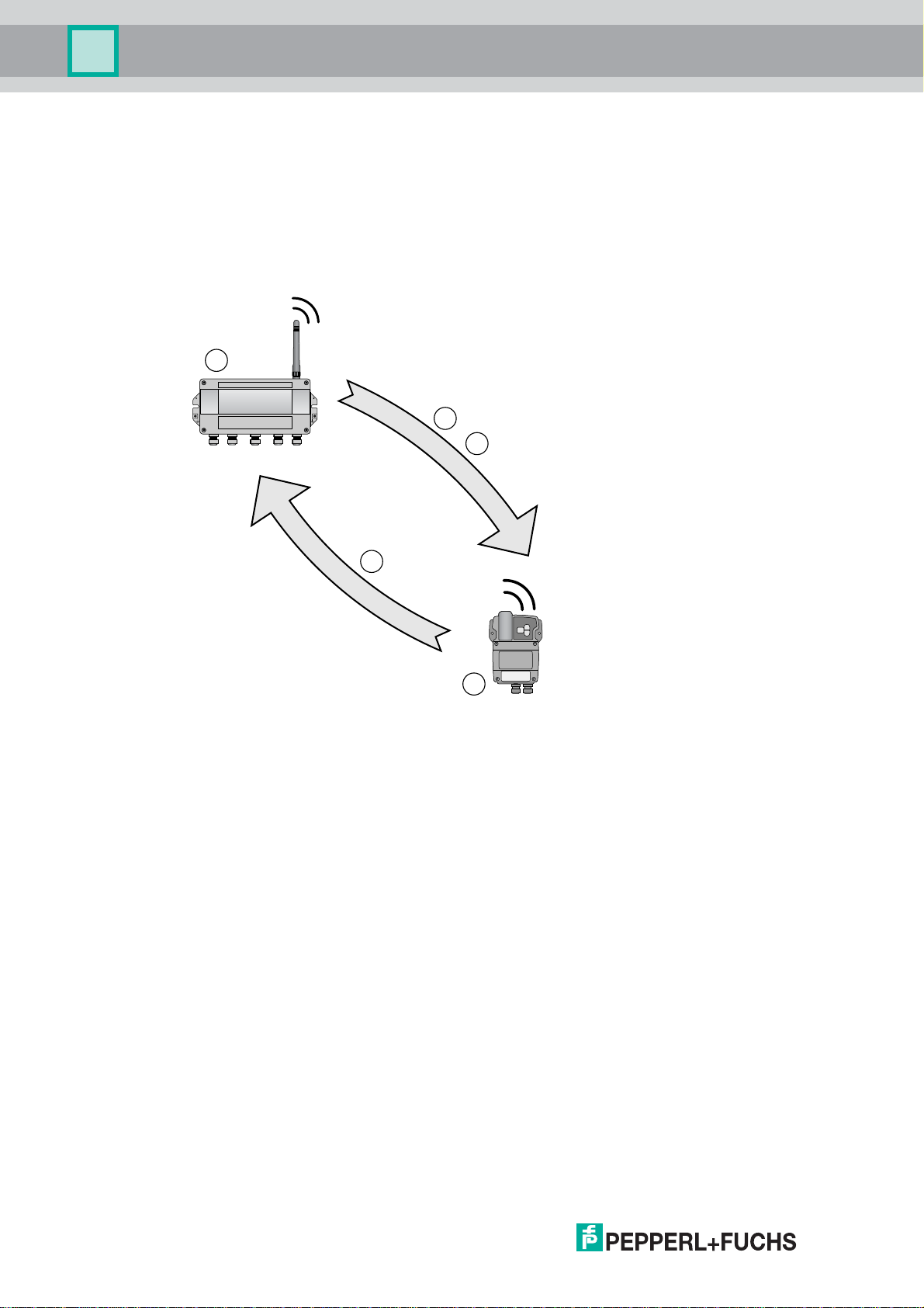
Figure 2.2Network management
1 Step 1: Advertising
2 Step 2: Joining
3 Step 3: Scheduling
4 WirelessHART Gateway
5 WirelessHART field device
First, the network manager sends advertising messages to announce the network’s
existence. When a WirelessHART field device receives such an advertising message, it
tries to join the network. If the WirelessHART field device can identify itself with the same
network ID and join key as stored in the WirelessHART Gateway, the field device is allowed
to join the network. Otherwise, the field device will be rejected.
The network manager can also instruct already joined devices to advertise on its behalf.
221981 2011-07
12
Page 13

WHA-GW-*
Product Specifications
In the next step, the network manager sends scheduling information to the field device. The
field device is told how to participate in the network and receives various information from
the WirelessHART Gateway:
• Number and identity of neighboring WirelessHART field devices,
• When to send messages and which channels to use,
• When to repeat messages for other WirelessHART field devices,
• The optimal communication path for messages as well as alternative communication
paths in case of failure.
During this process, the field device may also apply to send messages in certain intervals
and ask the network manager for the appropriate resources. The network manager then
takes care that these resources are available. For example, the network manager informs
other WirelessHART field devices when to repeat messages.
2.2.2 Security Management
The security manager is part of the WirelessHART Gateway. To make communication safe,
all messages are encrypted with industry-standard AES-128 block ciphers with symmetric
keys. Therefore, messages are unreadable for external listeners.
The security manager distributes the encryption keys and changes them in certain
(random) intervals, as an option.
2.2.3 Virtual Remote I/O system
The WirelessHART Gateway make wireless communication accessible to HOST systems
capable of HART technology through the following principles.
Instrument List
WirelessHART devices and wired devices connected to a WirelessHART adapter are made
available to HOST systems via a virtual HART I/O system. This I/O system contains one or
multiple I/O cards. Each I/O card has up to 2 channels. To each channel, up to 6 wired field
devices may be connected in multi-drop mode. (see Figure 2.3 on page 14).
The P+F WirelessHART Gateway assigns a virtual I/O card to each WirelessHART device
and stores card and channel values in the Instrument List. The I/O cards are assigned to
the WirelessHART devices in chronological order (0 ... 249). New WirelessHART devices in
the network are assigned to the next available I/O card.
WirelessHART devices are always assigned to Channel 0 of an I/O card. All wired devices
connected to a WirelessHART adapter are always assigned to channel 1 of the same I/O
card as the adapter (multi-drop mode).
221981 2011-07
13
Page 14
WHA-GW-*
Product Specifications
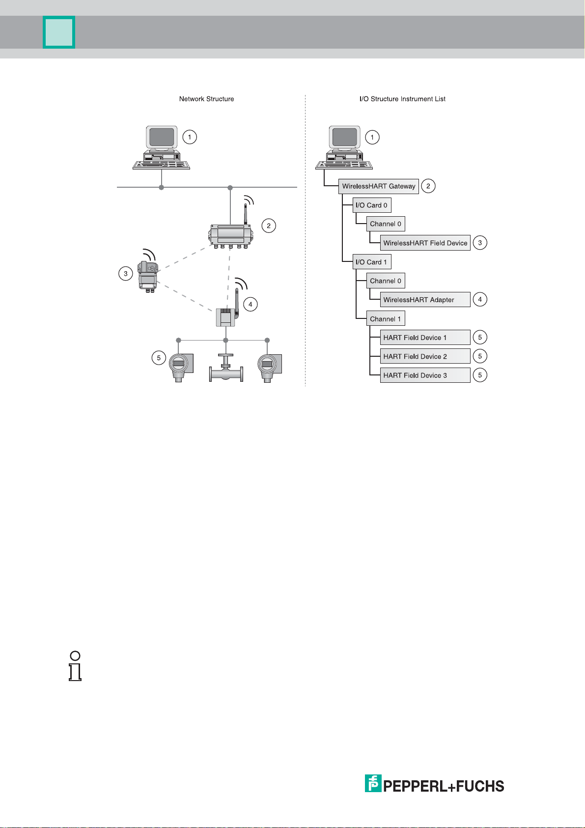
Figure 2.3Network structure and corresponding I/O structure
1 HOST application
2 WirelessHART Gateway
3 WirelessHART field device (joined first): I/O card 0, channel 0
4 WirelessHART adapter (joined second): I/O card 1, channel 0
5 Wired devices 1...3 connected to WirelessHART adapter: I/O card 1, channel 1
If a WirelessHART device loses communication to the Gateway, it keeps its position in the
Gateway's Instrument List and stays assigned to the respective I/O card. When
communication is established again, the device has the same channel/card values that it
had before.
The same principle applies to the field devices connected to the WirelessHART adapter:
After communication to the Gateway was lost, the field devices regain their previous
position in the Instrument List as soon as communication is established again.
Note!
The Instrument List is stored in a non-volatile memory. Card/channel number assignment
will remain the same after a Gateway power-up or software restart.
14
221981 2011-07
Page 15
WHA-GW-*
Product Specifications
Long Tag Emulation
The WirelessHART communication protocol uses the long tag to address devices.
However, long tags are only supported by HART 6 devices and newer devices
(HART 6 = version 6 of the HART communication protocol; current version: HART 7). Older
devices, for example HART 5 devices, have to be addressed by the "Message" field. If a
HART 5 device is connected to the WirelessHART network using a WirelessHART adapter,
the WirelessHART Gateway emulates the long tag with the "Message" field.
2.2.4 Gateway Cache Management
The WirelessHART Gateway caches parameters and dynamic values of the wireless and
wired subdevices and makes them available to the HOST. Some commands are cached by
the Gateway automatically (upon read). Other commands, for example dynamic values, are
only cached if the respective field device publishes them (upon publishing). For more
information on publishing of device values prease refer to the Burst lists section (see
chapter 5.4.3).
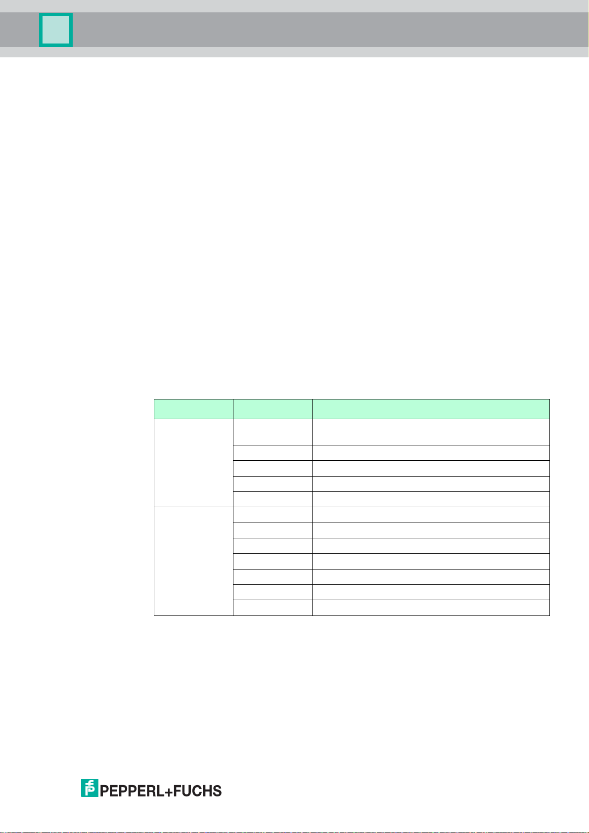
The responses to the command requests listed in the following table are cached in the
Gateway. Commands in the same row have an identical response frame and share the
same cache memory. The write commands (17, 18, 22, 51) will never get an immediate
answer, but their response will be cached (caching upon write-confirmation).
Information cached by the Gateway
Cache Command Description
Static
configuration
commands,
cached upon
read or upon
write
confirmation
Dynamic value
commands,
cached upon
publishing only
0, 11, 21 Read unique identifier (associated with tag or long
tag)
12, (17) Read (Write) Message
13, (18) Read (Write) Short Tag, Descriptor, Date
20, (22) Read (Write) Long Tag
50, (51) Read (Write) Dynamic Variable Assignments
1 Read Primary Variable
2 Read Current and Percentage
3 Read All Variables
9 Read Device Variables and Status
33 Read Device Variables
93 Read Trend
48 Read Additional Device Status
Status Information Caching
The Gateway chaches the device status byte separately for each wireless or wired device.
The device status will be cached from any type of received message, no matter if from a
wired or wireless device, or if it is a "published" or "normal" response.
The extended device status byte is cached in a similar way, but is available only for
wireless devices.
221981 2011-07
15
Page 16
WHA-GW-*
Product Specifications
2.3 Scope of Delivery
The scope of delivery of the WirelessHART Gateway includes:
•Device WHA-GW-*,
• Antenna W-ANT-2400-2DB-ROD,
• 3 sealing plugs for unused cable glands,
• Product documentation.
2.4 Design
The operating elements, connections and interfaces are accessible with open enclosure.
Controls and Indicators
Further information on the indications of the LEDs and the functions of the buttons and DIP
switches: see chapter 6.1.
16
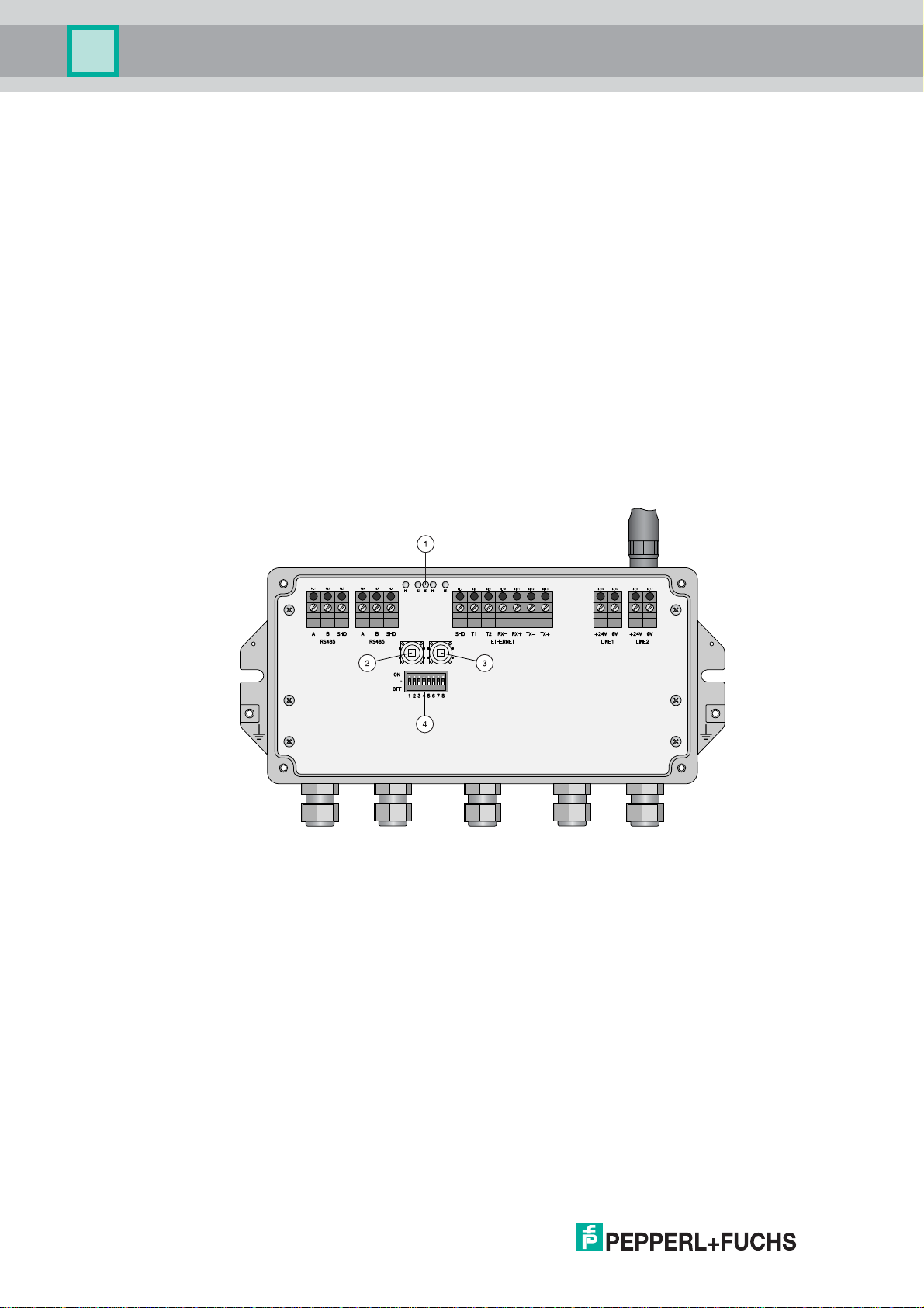
Figure 2.4WHA-GW with open enclosure
1 LEDs
2 Button A
3 Button B
4 DIP switches
221981 2011-07
Page 17
WHA-GW-*
Product Specifications
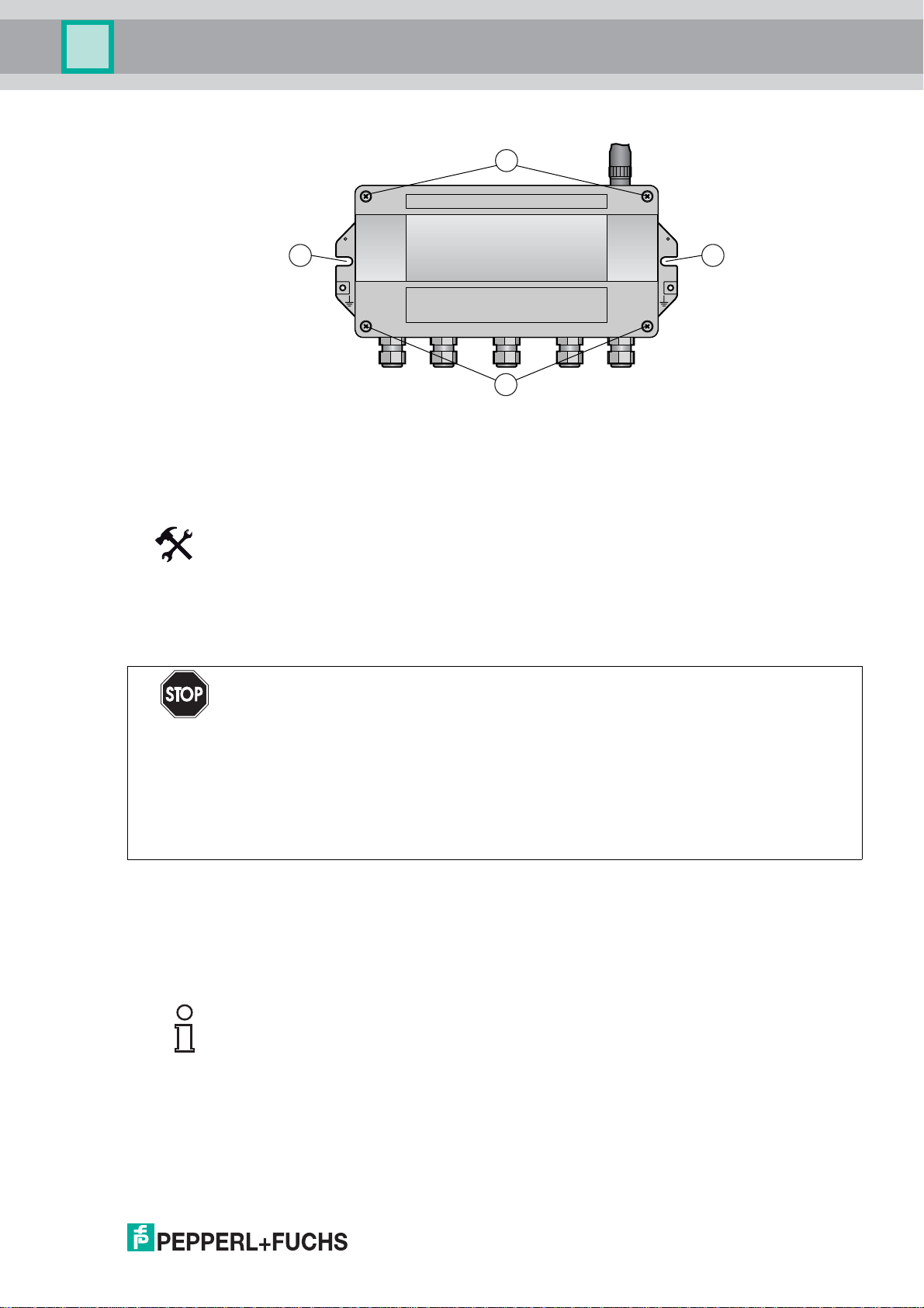
Connections and Interfaces
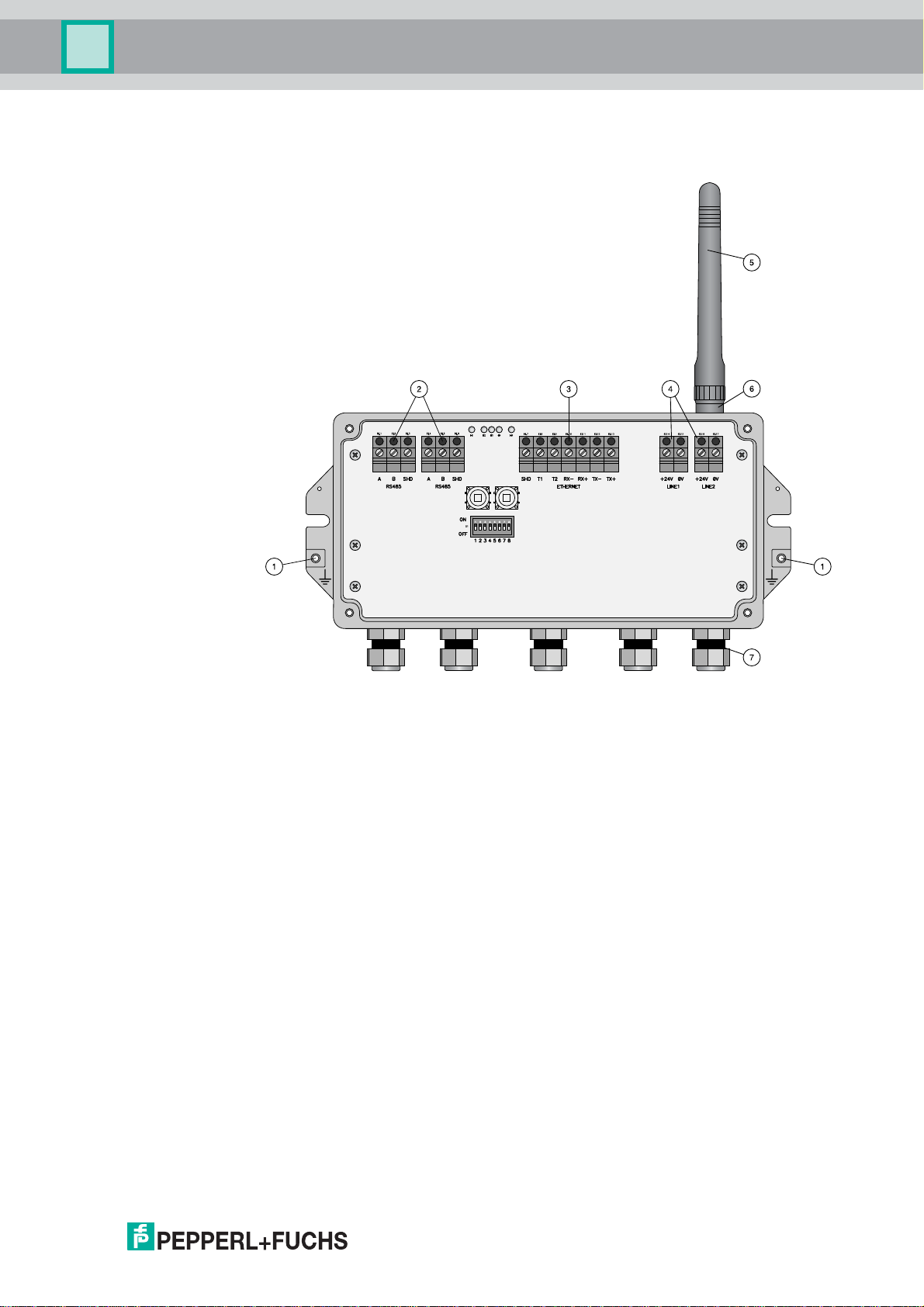
Figure 2.5Connections and Interfaces
1 Grounding terminal
2 RS-485 interfaces, duplicated terminal block for daisy-chain capability
3 Ethernet interface
4 Power supply connections (redundant)
5 Antenna
6 Antenna terminal
7 Cable glands
221981 2011-07
17
Page 18

WHA-GW-*
Installation
3Installation
3.1 Mounting Considerations
3.1.1 Positioning the Gateway
Install the Gateway first, before installing other WirelessHART devices. This way you can
check for proper operation of new devices as they are installed. Nevertheless, consider the
location of future WirelessHART devices that will be routed through the Gateway to ensure
good connectivity.
Guidelines for Planning a WirelessHART Network
• A line-of-sight between communication partners always is desirable. If a line-of-sight is
not possible, the obstacles should not be massive and the partners should be more to
the edge of an obstacle to allow the wave to "bend" around it (diffraction effect).
• Consider moving objects that could affect the device's antenna range.
• Install wireless devices at least 1 m above the ground or the floor.
• Make sure that the device's antenna is aligned vertically for best results.
• Make sure that a minimum of 2 other WirelessHART devices are well within the antenna
range of the device (see chapter 9). For more information on the antenna
characteristics please refer to the following section.
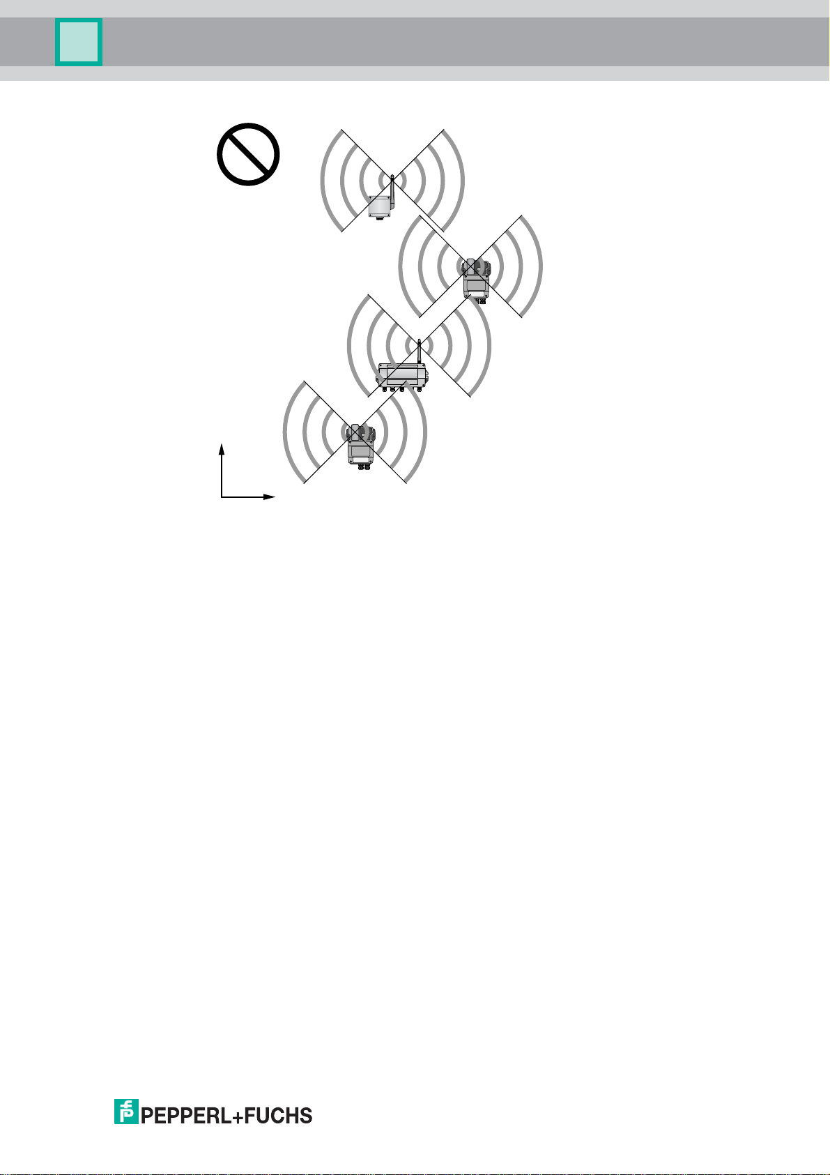
• Do not position WirelessHART devices directly below or above each other. They would
be outside each other's antenna range.
• Install WirelessHART devices at least 1 m away from each other.
• Antennas must be at least 6 cm away from any wall or any metallic material running
parallel to it.
• Position the device as far away as possible from metal surfaces or walls containing
metal. There should be as little metal close to the device as possible.
• Do not position other 2.4 GHz devices like cordless phone bases or WLAN routers near
WirelessHART devices. Keep in mind other wireless networks using the same
frequency spectrum (WLAN, Bluetooth, etc.). Wireless technologies used in an
industrial environment must be able to coexist without disrupting each other. If multiple
networks operate in one facility, a frequency management should be applied as part of
administration.
If it is not possible to mount the device outdoors, connect a remote antenna to the antenna
terminal and mount the remote antenna outdoors. The antenna cable should not be longer
than 15 m.
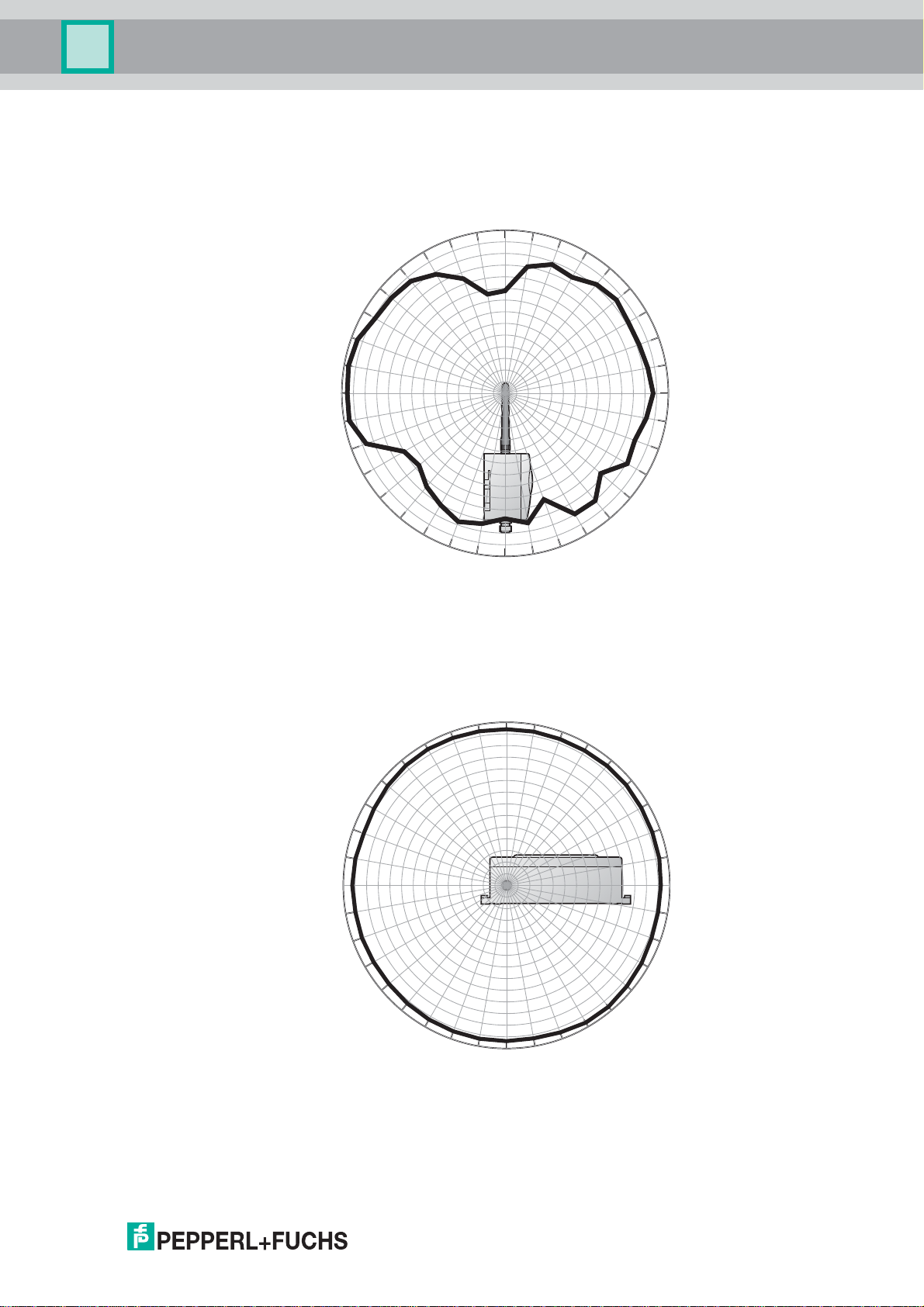
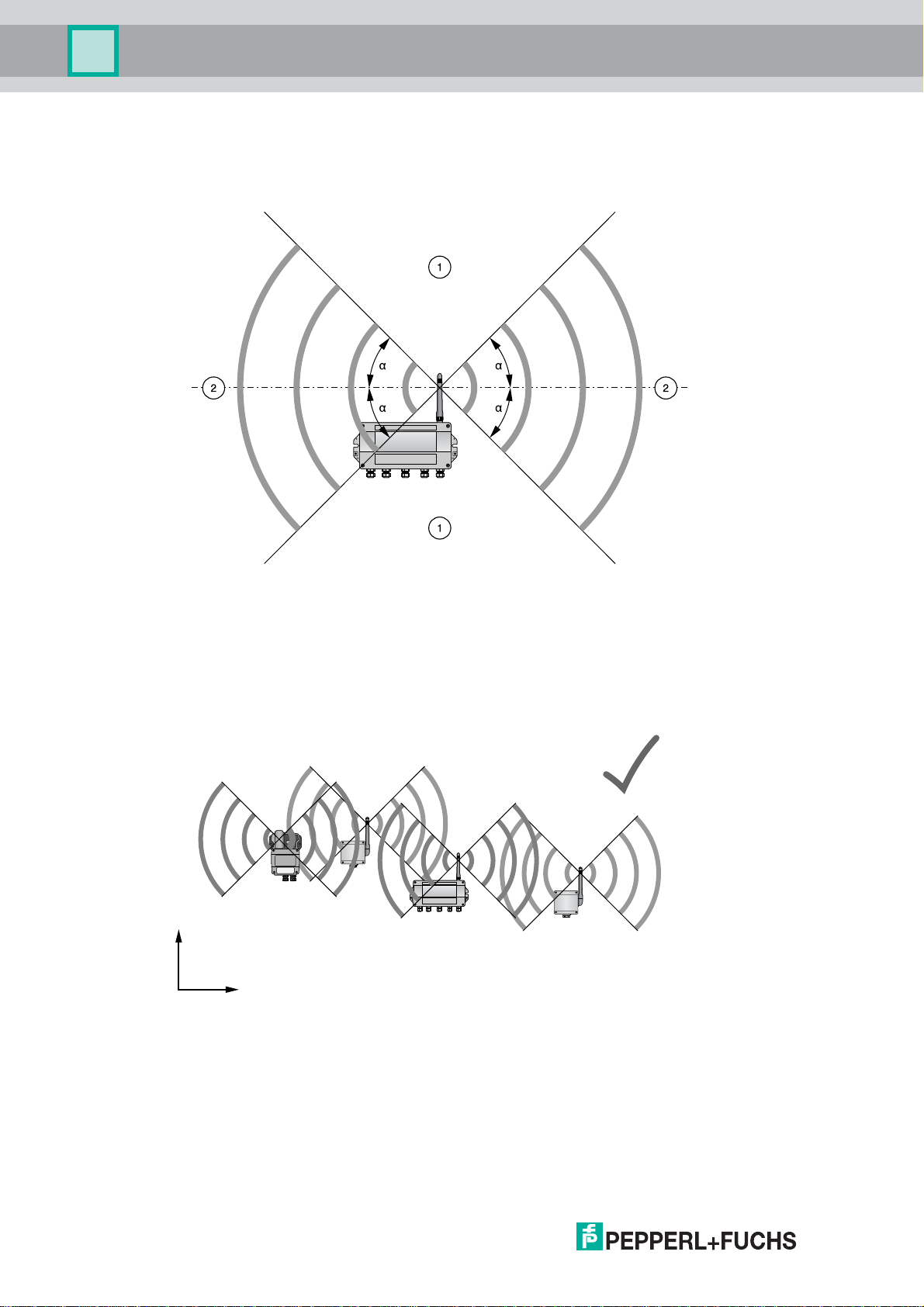
3.1.2 Antenna Characteristics
The antenna is an omni-directional dipole antenna. If you point the antenna upwards, the
signal radiates horizontally with an angle of approx. 45 degrees above and below the
horizontal (donut shaped). Allmost no signal will be radiated directly above and below the
antenna. Consider this when planning a WirelessHART network. The height differences
between wireless devices in a network should not be too big.
This is only valid for an antenna placed outdoors with no metal surfaces near. The radiation
pattern changes significantly when metal surfaces are close to the antenna.
18
221981 2011-07
Page 19
WHA-GW-*
Installation
The following diagrams show the antenna gain in two different planes.
0°
280°
270°
290°
300°
310°
320°
330°
340°
350°
2
-1
-4
-7
-10
-13
-16
-19
-22
-25
-28
-31
-34
-37
10°
20°
30°
40°
50°
60°
70°
80°
90°
260°
250°
240°
230°
220°
210°
200°
190°
Figure 3.1Antenna gain (side view, 2450 MHz, dBi)
350°
340°
330°
320°
310°
300°
290°
280°
270°
180°
0°
2
-1
-4
-7
-10
-13
-16
-19
-22
-25
-28
-31
-34
-37
170°
10°
100°
110
120°
130°
140°
150°
160°
20°
30°
40°
50°
60°
70°
80°
90°
260°
250°
240°
230°
220°
210°
200°
190°
180°
Figure 3.2Antenna gain (top view, 2450 MHz, dBi)
221981 2011-07
170°
160°
140°
150°
100°
110
120°
130°
19
Page 20
WHA-GW-*
x
y
Installation
3.1.3 Examples for Good and Poor Positioning
Figure 3.3Wave propagation, schematic representation (alpha = approx. 45°, may vary considerably)
1 Weaker signal above and below; almost no signal directly above and below
2 Stronger signal sideways
Figure 3.4Good positioning: Devices are within each others antenna range
221981 2011-07
20
Page 21
WHA-GW-*
x
y
Installation
Figure 3.5Poor positioning: Devices are not within each others antenna range
221981 2011-07
21
Page 22

WHA-GW-*
Installation
3.2 Mounting the Gateway
Danger!
Electrostatic discharge hazard
The device contains non-conductive plastic parts. Care must be taken when operating the
installed device because of possible electrostatic charges. Electrostatic charged surfaces
may cause an ignition spark.
Electrostatic charges must be avoided. For example, do not rub the device and never clean
plastic surfaces with a dry cloth. Always use a damp cloth instead.
Danger!
Check cable glands
The IP degree of protection can not be ensured if the cables and cable glands are not fitted
correctly.
To ensure the IP degree of protection
• all screws of the housing / housing cover must have been tightened with the appropriate
torque,
• only cables of the appropriate size must be used in the cable glands,
• all cable glands must be tightened with the appropriate torque,
• all seals must be undamaged and fitted correctly,
• all empty cable glands must be sealed with appropriate plugs.
The mounting location should be well accessible for mounting and electrical installation.
Make sure that there is enough space to open the housing cover and to access the
terminals, switches, and cable glands. Choose a mounting location that meets the
requirements of the climatic limits specified in the technical data.
The housing has a degree of protection of IP65 and is designed for wall mounting
(mounting accessories and tools not included).
Required tools
22
• 2 screws (M6)
• Drill
•Screwdriver
Depending on the mounting surface, you may need additional mounting material.
221981 2011-07
Page 23
WHA-GW-*
2
1 1
2
Installation
Figure 3.6Mounting holes and housing screws
1 Mounting holes for M6 screws
2 Housing screws
Mounting the Gateway
1. Drill 2 holes into the mounting surface so that they match the holes of the housing.
2. Screw the device to the mounting surface using M6 screws.
3.3 Connecting to Ethernet
Danger!
Explosion hazard in Zone 2 when operating powered Gateway
If the Gateway is installed in Zone 2 and connected to power, there is an explosion hazard
when operating DIP switches, buttons or connecting/disconnecting cables.
The operation of DIP switches/buttons and the connection/disconnection of any cables in
Zone 2 is only permitted in the absence of a hazardous atmosphere or if the device is
disconnected from power!
The Gateway is equipped with a fully galvanic isolated 10 Base-T/100 Base-TX Ethernet
interface. You may connect the Gateway to an existing Ethernet hub, switch, router or
directly to a PC.
Open the housing cover to access the terminal blocks.
Note!
Keep in mind that an access point of the Ethernet network has to be available. The
maximum length of the cable running from the Gateway to the access point is 100 m,
depending on cable type and communication speed.
221981 2011-07
23
Page 24
WHA-GW-*
Installation
Note!
Tension relief and bending radii
Ensure sufficient relief of tension on the cables during installation and note the minimum
bending radii of the cables.
Pin assignment of the Ethernet plug
You do not need an Ethernet plug to connect the Ethernet cable to the Gateway. However,
you need an Ethernet plug at the other end of the cable to connect the cable to an Ethernet
hub, switch, router or PC.
There are different standards for Ethernet plugs: T568A and T568B (see following
figure/table). The only difference between these standards is that certain wires are
connected to different pins of the plug. It is not important which standard the plug uses.
But, depending on the plug standard, there are two different ways of connecting the other
end of the Ethernet cable to the Gateway.
24
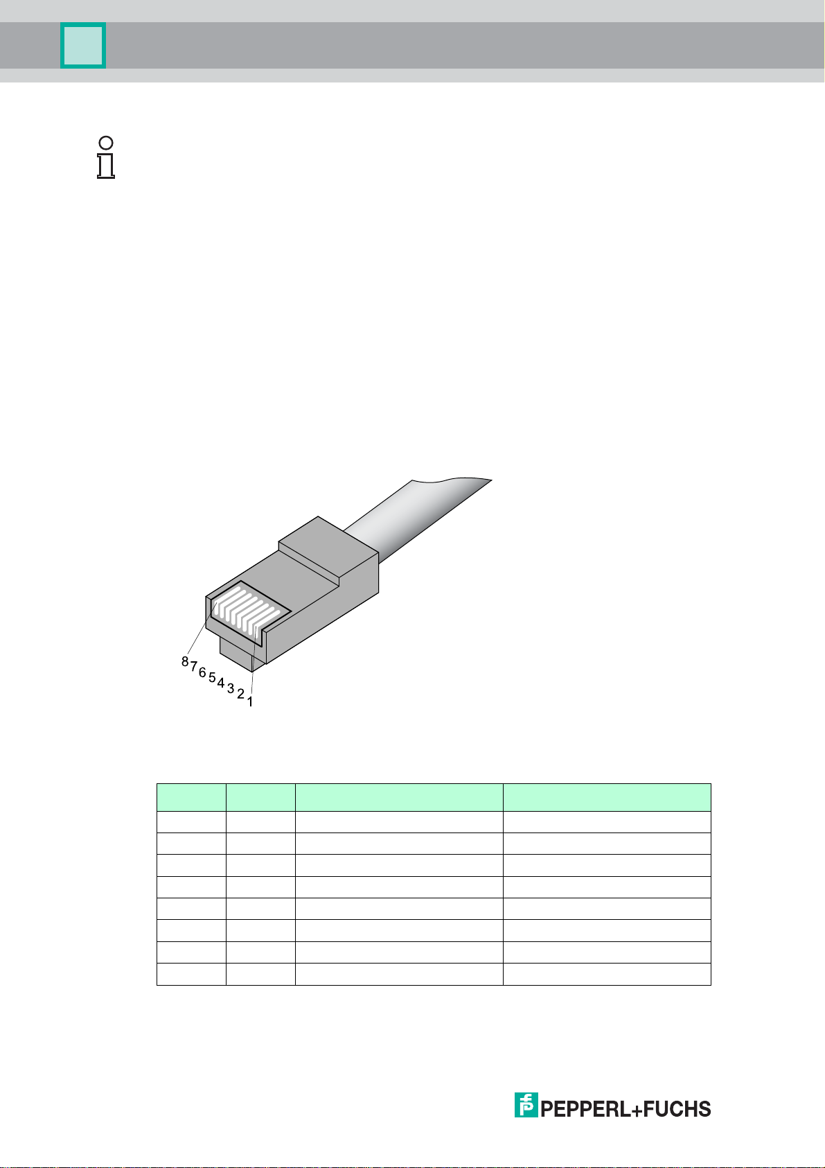
Figure 3.7Pin assignment RJ45 plug
Pin assignment of a T568A/T568B plug
Signal RJ45 Pin Wire color T568A Wire color T568B
TX+ 1 white/green white/orange
TX- 2 green orange
RX+ 3 white/orange white/green
4 blue blue
5 white/blue white/blue
RX- 6 orange green
7 white/brown white/brown
8 brown brown
Table 3.1Pin assignment of a T568A and T568B plug
221981 2011-07
Page 25
WHA-GW-*
1
3
2
4
2
Installation
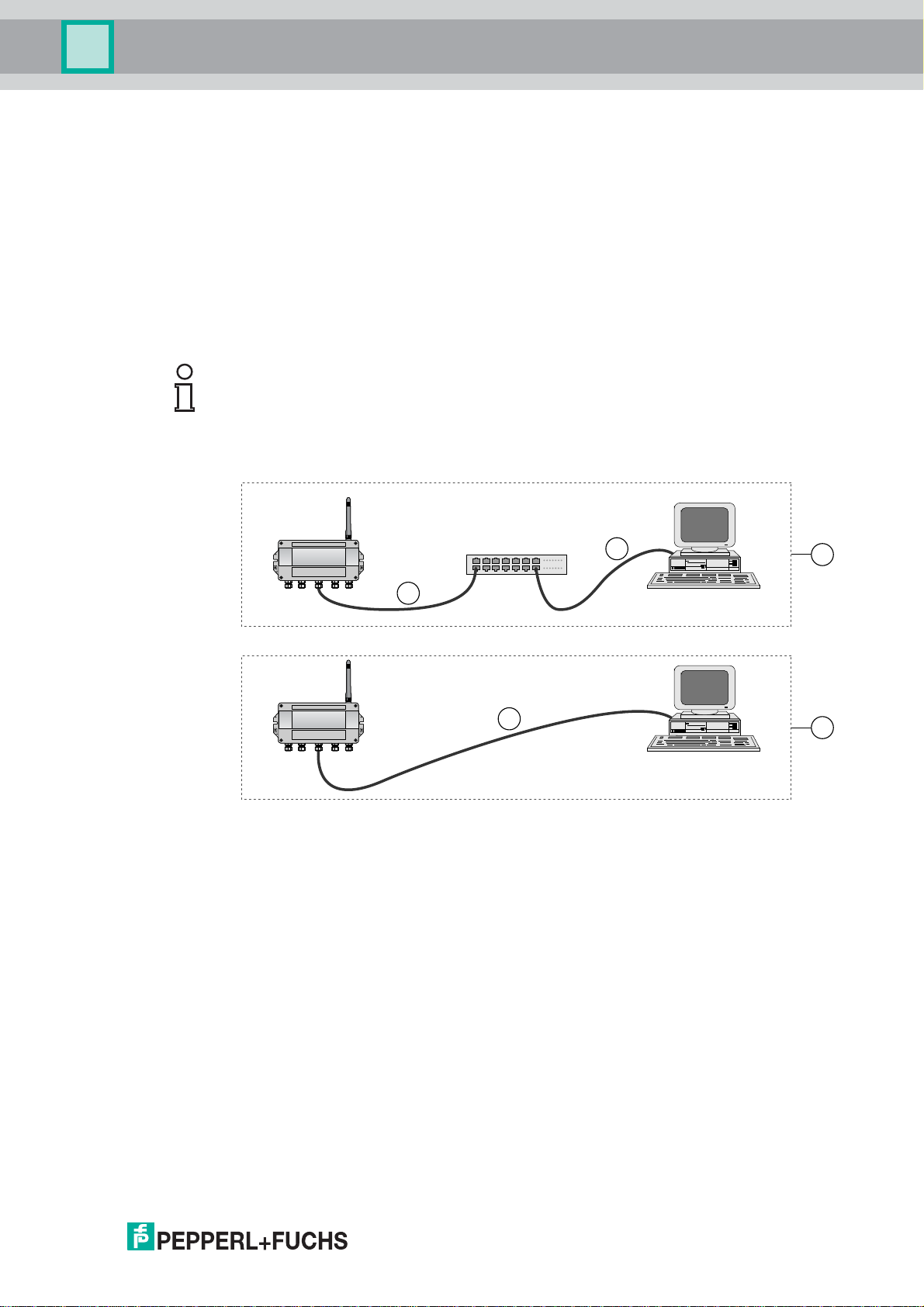
Crossover or straight through wiring
There are different types of Ethernet cables, depending on the application. In a straight
through cable, both cable ends have T568A plugs or both ends have T568B plugs. In a
crossover cable, one end has a T568A plug and the other end a T568B plug.
• Use straight through wiring if you connect the Gateway to a switch, hub or router (see
Figure 3.8 on page 25).
• Use crossover wiring if you connect the Gateway directly to another ethernet device
(e.g. a PC) without a switch, hub or router (see Figure 3.8 on page 25).
Note!
Latest network interface cards and hub/switch/router versions can be able to automatically
adjust to the cable version used, also if this is not the applicable one according to the
guidelines given in this manual.
Figure 3.8Straight Through or Crossover connection
1 Gateway connected to PC via hub/switch/router
2 Straight Through cable
3 Gateway connected directly to PC
4 Crossover cable
221981 2011-07
25
Page 26
WHA-GW-*
Installation
Connecting to Ethernet Network
1. Unscrew the 4 screws of the housing cover (see Figure 3.6 on page 23).
2. Remove the housing cover.
3. Route the Ethernet cable through the cable gland in the middle of the Gateway housing.
The permissible cable diameter lies between 6 ... 10 mm.
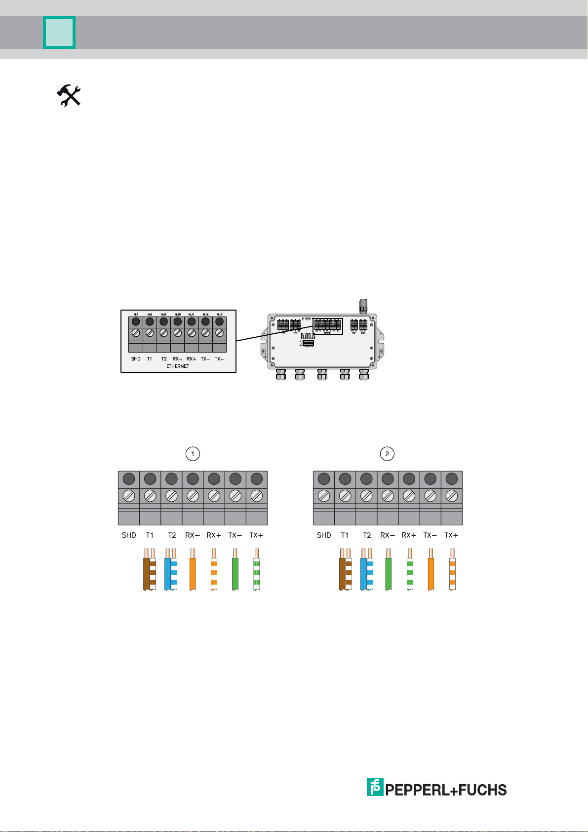
4. Connect the Ethernet cable to the terminal block labelled "Ethernet" (see Figure 3.9 on
page 26) according to the following figure/tables.
5. Screw the housing cover to the housing again.
6. Tighten the cable gland with appropriate torque (see table "Installation torque cable
glands" on page 32).
The Gateway is now connected to the Ethernet network. The yellow Ethernet
communication status LED starts flashing when a correct HART or Modbus protocol
message is received (see chapter 6.1).
Figure 3.9Ethernet interface
Figure 3.10Gateway Ethernet wiring
1 Straight through connection with an T568A plug
or
Crossover connection with a T568B plug
26
2 Crossover connection with an T568A plug
or
Straight Through connection with a T568B plug
221981 2011-07
Page 27
WHA-GW-*
Installation
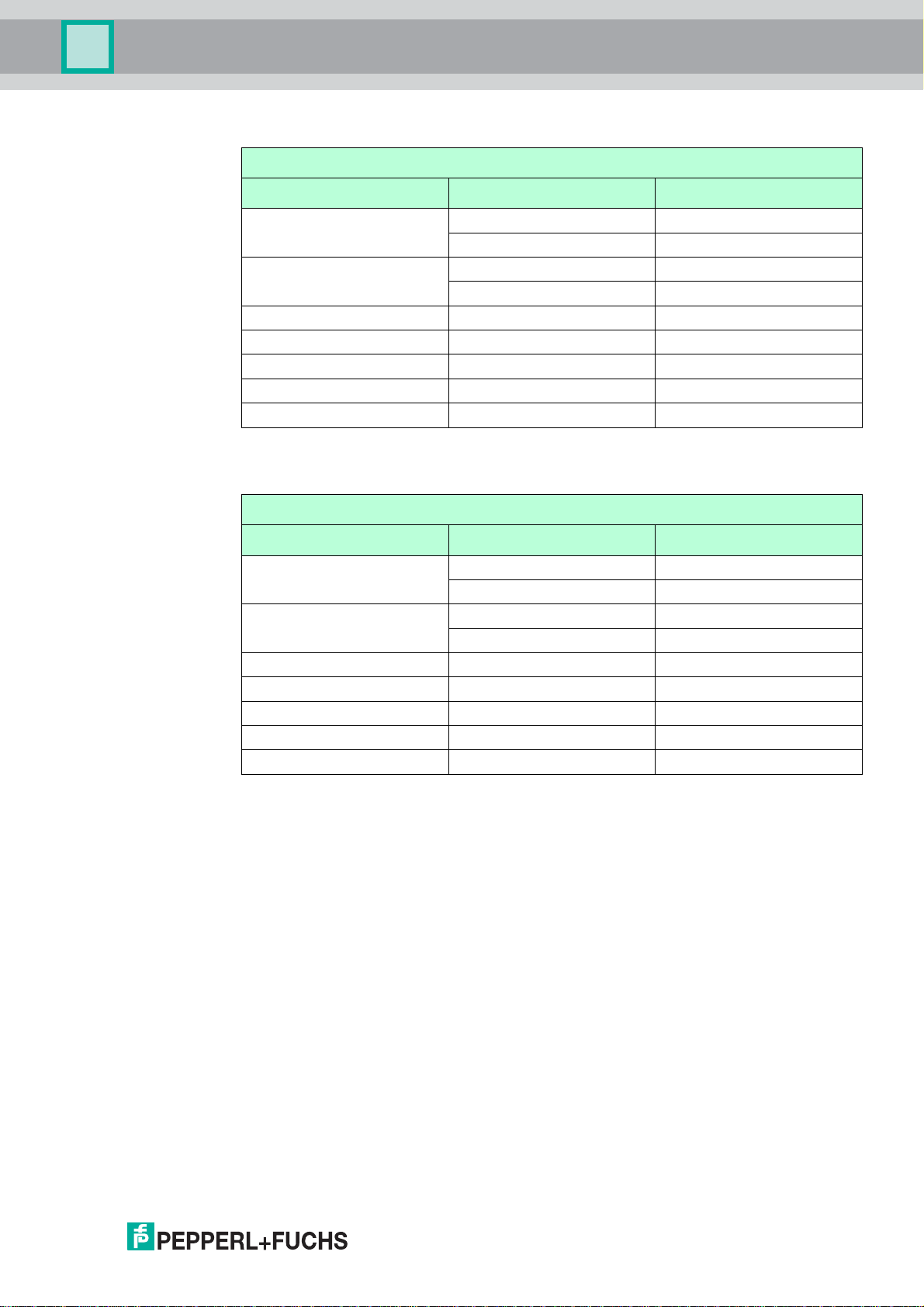
Wiring with a T568A plug
Gateway wiring with a T568A plug
Gateway Terminal Crossover wiring Straight through wiring
T1 brown brown
white/brown white/brown
T2 blue blue
white/blue white/blue
RX- green orange
RX+ white/green white/orange
TX- orange green
TX+ white/orange white/green
SHD Cable shield Cable shield
Table 3.2Wiring with a T568A plug
Wiring with a T568B plug
Gateway wiring with a T568B plug
Gateway Terminal Crossover wiring Straight through wiring
T1 brown brown
white/brown white/brown
T2 blue blue
white/blue white/blue
RX- orange green
RX+ white/orange white/green
TX- green orange
TX+ white/green white/orange
SHD Cable shield Cable shield
Table 3.3Wiring with a T568B plug
221981 2011-07
27
Page 28
WHA-GW-*
Installation
3.4 Connecting to RS-485
Danger!
Explosion hazard in Zone 2 when operating powered Gateway
If the Gateway is installed in Zone 2 and connected to power, there is an explosion hazard
when operating DIP switches, buttons or connecting/disconnecting cables.
The operation of DIP switches/buttons and the connection/disconnection of any cables in
Zone 2 is only permitted in the absence of a hazardous atmosphere or if the device is
disconnected from power!
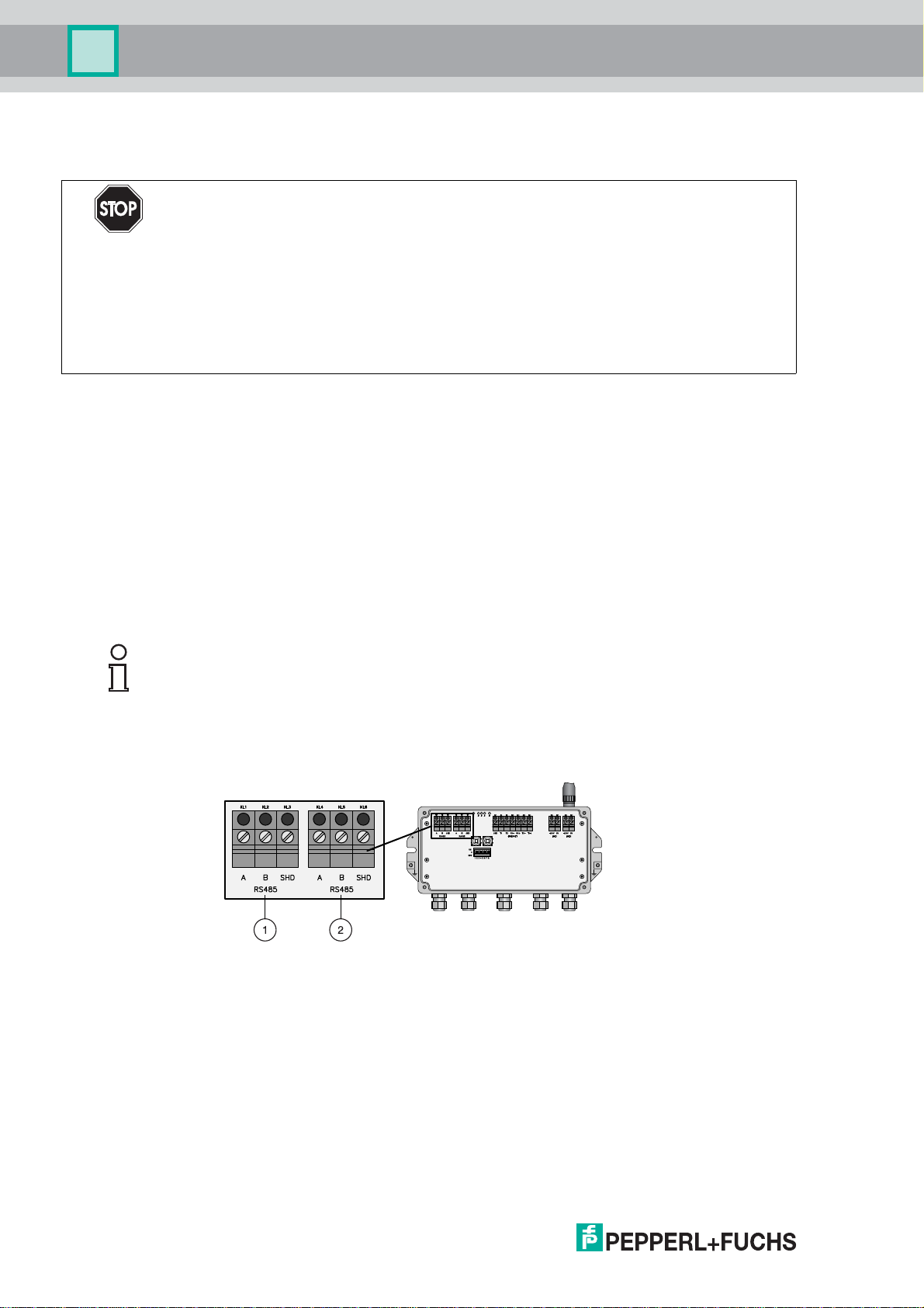
The Gateway is equipped with a fully galvanic isolated RS-485 interface. The interface is
daisy-chain capable through its duplicated RS-485 terminal block.
A terminating resistor is integrated and may be switched on/off by using the corresponding
DIP switch inside the Gateway housing (see chapter 6.1) . It is also possible to switch on/off
the terminating resistor via software (see chapter 5.5.1).
If the RS-485 cable ends at the WirelessHART Gateway and is not routed to other devices
(no daisy-chain connection), activate the terminating resistor to ensure reliable RS-485
communication.
Note!
Keep in mind the location of the Modbus PLC or DCS. The maximum length of the cable
running from the Gateway to the PLC/DCS is 1200 m (at reduced communication speed).
Use shielded twisted pair (STP) cables only.
Figure 3.11RS-485 interfaces
28
1 First RS-485 interface
2 Second RS-485 interface
221981 2011-07
Page 29
WHA-GW-*
Installation
Note!
Tension relief and bending radii
Ensure sufficient relief of tension on the cables during installation and note the minimum
bending radii of the cables.
Note!
If the cable shield is grounded, the grounding should only be connected to one end of the
cable, in order to avoid equipotential bonding currents.
Connecting to RS-485
1. Unscrew the 4 screws of the housing cover (see Figure 3.6 on page 23).
2. Remove the housing cover.
3. Route the STP cable through the first cable gland from left at the bottom of the Gateway
housing (see Figure 2.5 on page 17). The permissible cable diameter lies between
6...10mm.
4. Connect the STP cable to the first terminal block labelled "RS485" (see Figure 3.11 on
page 28) according to the following table.
5. For a daisy-chain connection, route the second STP cable through the second cable
gland from left at the bottom of the Gateway housing. Connect the second STP cable to
the second terminal block labelled "RS485" according to the following table.
6. To activate the RS-485 termination, set DIP switch number 7 to "ON" (see Figure 6.4 on
page 67).
7. Screw the housing cover to the housing again.
8. Tighten the cable gland with appropriate torque (see table "Installation torque cable
glands" on page 32).
The Gateway is now connected to the RS-485 network. The yellow RS-485
communication status LED starts flashing when a correct HART or Modbus protocol
message is received (see chapter 6.1).
Gateway wiring (RS-485 connection)
Wire RS-485 cable Terminal WHA-GW Meaning
RxD/TxD - (RS-485 A) A RS-485 differential signal
RxD/TxD + (RS-485 B) B
Shield SHD Cable shielding
221981 2011-07
29
Page 30

WHA-GW-*
Installation
3.5 Connecting the Antenna
Danger!
Loss of the device's certification
Only use antennas that are specified in the data sheet.
Danger!
Explosion hazard in Zone 2 when operating powered Gateway
If the Gateway is installed in Zone 2 and connected to power, there is an explosion hazard
when operating DIP switches, buttons or connecting/disconnecting cables.
The operation of DIP switches/buttons and the connection/disconnection of any cables in
Zone 2 is only permitted in the absence of a hazardous atmosphere or if the device is
disconnected from power!
An antenna is supplied with the device. However, if the device is mounted indoors, or if
there are many metal obstacles near the device, it is better to use a suitable remote
antenna instead.
The remote antenna should be installed outdoors in a position where it is within the
antenna range of other WirelessHART devices. To minimize signal loss, the cable
connecting the remote antenna to the Gateway should not be longer than 10 m.
The guidelines for positioning a WirelessHART device also apply to the positioning of a
remote antenna (see chapter 3.1.1).
Note!
Only antennas of the type W-ANT-2400-2DB-ROD or remote antennas with an antenna
gain 2 dBi may be connected to the device.
Connecting the antenna
Firmly screw the antenna or a a remote antenna to the device's antenna terminal (see
Figure 2.5 on page 17).
30
221981 2011-07
Page 31

WHA-GW-*
Installation
3.6 Connecting to Power Supply and Grounding
Danger!
Explosion hazard in Zone 2 when operating powered Gateway
If the Gateway is installed in Zone 2 and connected to power, there is an explosion hazard
when operating DIP switches, buttons or connecting/disconnecting cables.
The operation of DIP switches/buttons and the connection/disconnection of any cables in
Zone 2 is only permitted in the absence of a hazardous atmosphere or if the device is
disconnected from power!
There are two 24 V dc power supply terminal blocks located inside the Gateway, allowing
for redundant power supply. Open the housing cover to access the terminal blocks.
Note!
Tension relief and bending radii
Ensure sufficient relief of tension on the cables during installation and note the minimum
bending radii of the cables.
Figure 3.12Power supply
1 First power supply connection
2 Second (redundant) power supply connection
3 Grounding terminals
Connecting to Power Supply and Grounding
1. Connect one of the grounding terminals to a ground wire (see Figure 3.12 on page 31).
2. Unscrew the 4 screws of the housing cover (see Figure 3.6 on page 23).
3. Remove the housing cover.
4. Ensure that appropriate power is supplied.
5. Draw the power cable through the second cable gland from right (see Figure 2.5 on
page 17). The permissible cable diameter lies between 6 ... 10 mm.
6. Connect the power cable to the first power supply connection "Line 1" observing polarity
(see Figure 3.12 on page 31).
221981 2011-07
31
Page 32

WHA-GW-*
Installation
7. If you want to connect a redundant power supply (optional), draw the second power
cable through the cable gland on the far right of the housing.
8. Connect the second power cable to the second power supply connection "Line 2"
observing polarity.
The Gateway is connected to power supply. The green power LED may remain off for
up to 40 seconds after connection to power (system boot-up).
9. Tighten the cable glands with appropriate torque (see table "Installation torque cable
glands" on page 32).
10.Seal empty cable glands with the provided plugs.
Note!
The tightening torques of cable glands depend on what type of cable is used and must
therefore be determined by the user. The cap nuts must be securely tightened. Tightening
the cap nuts too tight can have a negative effect on the protection class. The following
figures should be taken as rough guides only.
Installation torque cable glands
Type of cable glands Installation torque cable glands
Plastic 2.5 Nm
Nickel plated brass 4.11 Nm
Stainless steel 4.11 Nm
Table 3.4Installation torque cable glands
Danger!
Check cable glands
The IP degree of protection can not be ensured if the cables and cable glands are not fitted
correctly.
To ensure the IP degree of protection
• all screws of the housing / housing cover must have been tightened with the appropriate
torque,
• only cables of the appropriate size must be used in the cable glands,
• all cable glands must be tightened with the appropriate torque,
32
• all seals must be undamaged and fitted correctly,
• all empty cable glands must be sealed with appropriate plugs.
221981 2011-07
Page 33

WHA-GW-*
Commissioning
4 Commissioning
4.1 Important Steps to Getting Started
There are different possibilities how to connect to the gateway and how to configure the
gateway. The following overview tells you which steps to take. But first, please answer the
following question.
Are you going to configure the gateway via DTM software or via the browser-based web
interface?
• DTM software: Please follow the instructions given in "Configuring via DTM software"
below.
• Web interface: Please follow the instructions given in "Configuring via browser-based
web interface" below.
Configuring via DTM software
1. Download and install the following software components, if not already installed: Mi-
crosoft
(see chapter 4.2).
®
.NET Framework, PACTware® Framework, DTM Collection, HART CommDTM
2. Connect to the gateway via the RS-485 interface (see chapter 4.4) or the Ethernet
interface (see chapter 4.5).
3. Create a new PACTware project (see chapter 4.6).
4. Configure the gateway via DTM (see chapter 5.1).
Configuring via browser-based web interface
1. Download and install a web browser, if not already installed (Microsoft® Internet Explorer
v7 or higher, Mozilla Firefox v3 or higher).
2. Connect to the gateway via the Ethernet interface (see chapter 4.5).
3. Configure the gateway via your web browser (see chapter 5.1).
4.2 DTM Software
4.2.1 Downloading the required software
Required software:
®
•Microsoft
• PACTware
• WirelessHART DTM
The DTM collection including WirelessHART device DTMs and Ethernet communication
DTM.
.NET Framework
TM
Framework
• HART CommDTM
The HART CommDTM has to be installed separately if serial HART communication via
the Gateway's RS-485 interface is required. The HART CommDTM supports both
FSK (i.e. HART modem) and RS-485 interfaces.
221981 2011-07
33
Page 34

WHA-GW-*
Commissioning
Note!
If one of the software components is already installed on your system, the installation may
be omitted.
Where to download the required software?
1. Visit www.pepperl-fuchs.com and scroll down to the bottom of the page until you see the
2. Click on the Process Automation link.
3. In the Process Automation Products menu, click on the Software link.
4. Now download the software components Microsoft
area Pepperl+Fuchs International site links.
The Process Automation main page is loaded.
The Software main page is loaded.
®
.NET Framework, PACTware®,
WirelessHART DTM and, if required, the HART CommDTM. You might need to scroll
down the page to find the required component.
5. Unzip the downloaded files and store the data to your local hard drive.
4.3 Installing the Required Software
Hardware requirements for PACTware® and the device DTM:
®
•IBM
• Processor Intel/AMD min. 500 Mhz,
• min. 256 MB RAM,
• min. 200MB free disk space,
• Graphics resolution 1024 x 768.
Software requirements for PACTware
• Windows 2000 Service Pack 4, Windows XP Service Pack 1/2/3 or Windows Vista,
•Microsoft
• unzip software.
Note!
You need to be logged on to Windows with administrator privileges during installation.
or compatible PC,
®
and the device DTM:
®
.NET Framework Release 1.1 Service Pack 1,
221981 2011-07
34
Page 35

WHA-GW-*
Commissioning
Installing the required Software
1. Install the Microsoft® .NET Framework by starting the corresponding setup.exe file and
following the installation instructions given on the screen.
2. Install PACTware
installation instructions given on the screen.
3. Install the WirelessHART DTM collection by starting the corresponding setup.exe file
and following the installation instructions given on the screen.
4. Install the HART CommDTM by starting the corresponding setup.exe file and following
the installation instructions given on the screen.
You have installed the required software.
4.3.1 Updating the DTM catalog
After you have installed the FDT base application and the new DTMs onto the computer, it
may be necessary to update the DTM catalog. In PACTware, the DTM catalog is called the
"device catalog" and is usually updated automatically when PACTware starts up.
If PACTware does not automatically update the device catalog, proceed as follows.
®
by starting the corresponding setup.exe file and following the
Updating the device catalog
1. Start PACTware.
2. Select View > Device catalog or press the F3 key or click the Device catalog icon on
the toolbar.
The Device catalog window opens.
3. Click the Update device catalog button to update the device catalog (see on page 35).
Device catalog in PACTware
4. Click Yes to confirm the next prompt.
The program then searches for recently installed DTMs (see on page 35). The updated
device catalog appears once the search has finished.
221981 2011-07
Search for DTMs in PACTware
35
Page 36

WHA-GW-*
Commissioning
4.4 Connecting via RS485
Once the Gateway has been connected to the RS485 bus (see chapter 3.4), you may
connect the RS485 bus to your PC. This can be done by using a RS485–RS232 converter
or a RS485–USB converter.
Note!
The usage of an approved RS-485 converter is recommended for faster configuration and
more reliable high-speed operation. In addition, the usage of a galvanically isolated RS485 converter is strongly recommended for permanent installations.
Connecting via RS485
1. Connect the RS485–RS232 converter or the RS485–USB converter to your PC.
2. To find out to which COM port the converter is connected, open the Windows
manager (Windows XP: Start > Settings > Control Panel > System > Hardware > Device
Manager).
®
device
3. Under "Ports (COM & LPT)" you should see the converter and the COM port assigned
to it (see on page 36). You will need the COM port number later on.
View of the USB converter in the Windows
®
device manager
221981 2011-07
36
Page 37

WHA-GW-*
Commissioning
4.5 Connecting via Ethernet
Once the gateway has been connected to the Ethernet (see chapter 3.3), you are ready to
connect your PC.
Connecting to the gateway via Ethernet
1. Connect the Ethernet cable to the Ethernet jack of your PC.
2. To communicate with the gateway, you need to configure the IP address and subnet
mask of your PC. To do this, launch the Network Connections window (Windows
Start > Settings > Control Panel > Network Connections).
3. Right-click on the icon Local Area Connection and choose Properties from the
context menu.
The Local Area Connection Properties window opens.
®
XP:
Local Area Connection Properties window
4. Select the list entry Internet Protocol (TCP/IP).
5. Press Properties.
The Internet Protocol (TCP/IP) Properties window opens.
221981 2011-07
37
Page 38

WHA-GW-*
Commissioning
Entering IP address and subnet mask
6. Choose Use the following IP address and type 192.168.1.100 into the field IP
address.
7. T y p e 255.255.255.0 into the field Subnet mask.
8. Press OK.
Your PC is now ready to communicate with the gateway.
4.6 Creating a new PACTware Project
4.6.1 Creating a new project
Creating a new project in PACTware
Select File > New or click the Create new project icon on the toolbar.
A new, unnamed project appears in the main window. The project initially consists of the
entry Host PC.
4.6.2 Adding the Communication DTM
®
A communication DTM is an interface between the FDT frame application and the device
DTM. The communication DTM enables communication between the device DTM and the
device connected to the PC.
Depending on how your PC is connected to the Gateway (via RS485 or Ethernet), you
need to add a corresponding communication DTM to your PACTware project. The RS485
communication DTM is the HART Communication DTM, and the Ethernet communication
DTM is called HART IP Communication.
221981 2011-07
38
Page 39

WHA-GW-*
Commissioning
Adding RS485 Communication DTM
Note!
The HART CommDTM is not included in the WirelessHART DTM Collection. It can be
downloaded separately from www.pepperl-fuchs.com. For further information on
downloading and installing the DTM, see chapter 4.2.
1. Select the entry HOST PC in the project view of your PACTware project.
2. Choose or click the Add device icon on the toolbar.
Device > Add device
The Device for window appears (see on page 39).
Selection of HART communication DTM
3. Select the entry HART Communication.
4. Click OK.
The HART communication DTM is added to the project.
HART communication DTM in PACTware project
5. To edit the parameters, double-click on the HART communication DTM.
The parameter window appears.
221981 2011-07
39
Page 40

WHA-GW-*
Commissioning
Parameter window of HART communication DTM
6. Set the parameters according to the following table.
7. Click OK to save the changes and to close the parameter window.
Parameter Description Default
Communication
interface
Port Set this parameter to the COM port your
Baudrate Set the baudrate according to the settings of the
RTS Control Depending on the RS485–RS232 converter used, it may
Master Specify if you want the Gateway to be the primary or the
Preamble Number of preambles for HART communication. 5
Number of
communication
retries
Start address Here the address range is set, in which the HART
End address 15
Set this parameter to HART multiplexer. HART
modem
COM1
RS485–RS232 converter or your RS485–USB converter
is connected to (see chapter 4.4).
19200
Gateway's baud rate. The Gateway's baud rate can be
adjusted via the DIP switches inside the Gateway housing
(see chapter 6.1) or via software (see chapter 5.5.3, see
chapter 5.5.4).
Toggle
be necessary to switch on or off the request-to-send
control in order to be able to switch over correctly between
reception and transmitting mode
Primary
secondary master. If, for example, there already is a
primary master connected, you have to choose
Secondary master.
The number of retries for HART communication in case of
an error.
Communication DTM is to search for HART Multiplexers
connected to the RS 485 bus.
Master
3
0
221981 2011-07
40
Page 41

WHA-GW-*
Commissioning
Adding Ethernet Communication DTM
1. Select the entry HOST PC in the project view.
2. Choose Device > Add device or click the Add device icon on the toolbar.
A device selection window opens (see on page 41).
Selection of the communication DTM
3. Select the entry HART IP Communication.
4. Click OK.
The Ethernet communication DTM is added to the project.
Ethernet communication DTM in PACTware project
5. To edit the parameters, double-click on the HART IP Communication DTM.
The parameter window appears.
221981 2011-07
41
Page 42

WHA-GW-*
Commissioning
Parameter window of Ethernet communication DTM
6. Set the parameters according to your preferences. In most cases, the default values
7. In some cases you might have to edit the Additional Functions > Set DTM addresses
8. Click OK to save the changes and to close the parameter window.
Editing Additional Functions > Set DTM addresses of the HART IP
Communication DTM
The Additional Functions > Set DTM addresses menu contains settings which are
important for establishing a connection between the communication DTM and the
Gateway. The IP address, bus address and UDP port set in this menu must match the
corresponding parameters set in the gateway. When using a new Gateway, there is no
need to change the following parameters, because the default settings of the gateway
match the default settings of the HART IP Communication DTM.
should be fine.
menu. Please read the following instructions for further information.
1. Right-click on the entry HART IP Communication.
Ethernet communication DTM in PACTware project
A context menu is displayed.
2. Choose Additional Functions > Set DTM addresses.
The Set DTM addresses window is displayed.
HART IP Communication > Additional Functions > Set DTM addresses
3. Change the parameters as required (see following table).
4. Press Update changed data to apply the new settings.
5. Disconnect and reconnect the communication and the Gateway DTM to activate the
221981 2011-07
new settings.
42
Page 43

WHA-GW-*
Commissioning
HART IP communication DTM parameters Corresponding Gateway parameters
Parameter Explanation Default Parameter Default
Tag Gateway name in the
Project view of
PACTware. Any name
may be entered (not
relevant for
connection to
gateway)
Bus
Address
UDP
Address
UDP Port Gateway port number
Gateway polling
address; must match
the settings of the
Gateway.
IP address of the
Gateway; must match
the settings of the
Gateway.
(HART over UDP);
must match the
settings of the
Gateway.
4.6.3 Adding Device DTM
Adding the Device DTM
WHA-GW – –
1 Parameterization
> Wired Communication
> Protocols > HART
> Bus Address
192.168.1.1 Parameterization
> Wired Communication
> Interfaces > Ethernet
> IP Address
5094 Parameterization
> Wired Communication
> Protocols > HART
> Port Number
1
192.168.1.1
5094
1. In the project view, right-click on the entry of the communication DTM you have added in
the previous step.
2. To add the device DTM, choose Add device.
The Device for window opens (see on page 43).
Device for window with Gateway DTM
3. Select the entry WHA-GW.
221981 2011-07
43
Page 44

WHA-GW-*
Commissioning
4. Click OK.
Gateway DTM in the PACTware project view
5. Remember to save your PACTware project from time to time (File > Save).
The Gateway DTM is added to the project (see on page 44). You may continue with
parameterizing the Gateway as described in the following (see chapter 5).
221981 2011-07
44
Page 45

WHA-GW-*
Configuration
5 Configuration
5.1 Configuration via DTM or Web Interface
There are two possible ways of configuring the device:
• Configuration via the device DTM within an FDT frame application, e.g. PACTware
• Configuration via a browser-based web interface.
The main difference is the concept of offline/online parameterization when configuring with
DTM/FDT (see chapter 5.2). This concept does not apply to browser-based configuration,
because browser-based parameterization is always an online parameterization.
Note!
In the following sections, only the configuration via DTM and PACTware
However, because both approaches are similar, you may also use the given information as
a guideline for browser-based configuration.
®
is described.
®
.
Diagnosis > Wired Communication and Diagnosis > Health Status are only available
via the web interface (see chapter 6.2). In comparison to the DTM, the web interface only
has the additional functions Reset and About (see chapter 6.3).
Configuring via DTM/FDT
1. Make sure that your PC is connected to the Gateway via RS485 (see chapter 4.4) or via
Ethernet (see chapter 4.5).
2. Start PACTware and load your project file (see chapter 4.6).
3. Make sure that you have added the appropriate communication DTM (see chapter
4.6.2) and the device DTM (see chapter 4.6.3) to your PACTware project.
4. Parameterize the Gateway online or offline as described in the following sections.
Configuring via web interface
Note!
The connection to the web interface is made using a secure connection (HTTPS) which
requires a user name and a password. The factory default settings are:
User name: admin
Password: admin
You can change both user name and password in the web interface (Additional functions >
Change Password, see chapter 6.3.7)
1. Make sure that your PC is connected to the Gateway via Ethernet (see chapter 4.5).
2. Start your web browser.
3. If your web browser uses a proxy, then deactivate the proxy. The proxy setting
normally can be found in the connection properties of your browser (where exactly
depends on your type of browser).
221981 2011-07
45
Page 46

WHA-GW-*
Configuration
4. Type the IP address of the Gateway into the browser's address field. The factory default
is 192.168 .1.1. If you have already changed the Gateway's IP address, type in the new
IP address. NOTE: In some browsers, you might have to clear the address history first
or add "/index.html" after the IP address.
Depending on the browser you use, some messages might pop up informing you about
the secure connection and the security certificate. In this case, click "OK", "Proceed", or
similar options. Do not cancel the procedure.
A window is displayed asking you for your user name and password (see on page 46).
Entering login data for secure connection
5. Enter your user name and password.
6. Click OK.
You are directed to the Gateway's web interface.
7. Change the parameters as needed. Press Enter to accept a new value. The DTM
parameters described in the following sections also apply to browser-based
configuration.
5.2 Online and offline parameterization (DTM)
Note!
This section only applies to parameterization via FDT/DTM.
The device DTM provides dialogs for offline and online parameterization.
• Offline parameterization (not connected to device): If there is no active connection to
the device, only the device data stored in the PACTware project can be edited and
saved to the PACTware project again. You may write the offline data record into the
device as soon as a connection has been established.
To ensure that the data you are editing is up to date, first load the data from the device
when its online and then edit the data offline.
• Online parameterization (connected to device): If there is an active connection to the
device, the device data stored in the device can be edited directly (online). Parameter
changes are stored to the device immediately.
The online and offline data are updated using the commands Store to device and Load
from device.
221981 2011-07
46
Page 47

WHA-GW-*
Configuration
Note!
The data edited and stored in the device during online parameterization is not automatically
synchronized with the offline data record in the PACTware project. If you only change
device parameters online, the device data stored in the project differs from the data stored
in the device!
To ensure that the device data stored in the PACTware project always matches the data
stored in the device, load the device data into the project after parameterizing online.
Parameterizing offline
1. Right-click the device entry in the PACTware project.
A context menu opens.
2. Choose Parameter > Offline Parameterization.
The window containing the offline data record appears.
3. Modify a parameter by typing in a new value or choosing a new value from the dropdown list.
4. To accept the new value, press Enter.
5. After all parameter changes have been made, save your project by choosing File >
Save.
6. To store the new offline configuration to the device, right-click on the device entry in the
project view and choose Connect.
A connection to the device is established.
7. Right-click on the device entry again and choose Store to device.
The new configuration is stored to the device.
Parameterizing online
1. Right-click the device entry in the PACTware project.
A context menu opens.
2. Select Connect.
A connection to the device is established.
3. Right-click the device entry in the PACTware project.
4. Select Parameter > Online Parameterization.
The window containing the online data record opens (data is read from the device).
5. Modify a parameter by typing in a new value or choosing a new value from the dropdown list.
6. To accept the new value, press Enter.
The new value is stored to the device immediately.
7. After all parameter changes have been made, you may store the online configuration
into the PACTware project. To do this, right-click on the device entry in the project view
and choose Load from device.
The device date is stored into the PACTware project.
8. Save your project by choosing File > Save.
221981 2011-07
47
Page 48

WHA-GW-*
Configuration
Note!
Many device parameters can be edited both online and offline. The parameters that can
only be edited online are especially pointed out in the following sections.
5.3 Identification Parameters
The identification parameters provide various information about the device and identify the
device within the network.
Figure 5.1Identification parameters
Identification Parameters
Parameter Description Default
Device Long Tag Identifies the device in a WirelessHART network. Enter up
to 32 characters.
Device Tag Identifies the field device within the process plant. Enter up
to 8 characters.
Descriptor Further description of the device. Enter up to 16
characters.
Date User-defined date (e.g. last parameter change). Format:
DD.MM.YYYY
The Date parameter is not modified by the Gateway itself.
Instead is has to be set by the user or Host application.
Message User-defined message. Enter up to 32 characters. –
Country Code Select the country code of the country in which the device
is operated from this drop-down list.
Table 5.1Identification Parameters
221981 2011-07
–
–
–
–
–
48
Page 49

WHA-GW-*
Configuration
5.4 Wireless Communication Parameters
5.4.1 Setup
The setup parameters contain the necessary information for establishing and maintaining a
WirelessHART network.
Figure 5.2Wireless Communication Parameters > Setup
Note!
Parameter Join Key
The parameter Join Key can only be edited when the security mode is activated by means
of a DIP switch inside the gateway housing. To activate the security mode, set DIP switch 8
to ON (see Figure 6.4 on page 67). In the security mode it is possible to use CMD 768
HART command to set the gateway join key as required.
Caution!
Network security risk
For security reasons do not to use the security mode connection as a normal
communication channel. After having changed the join key, disable the security mode again
using the DIP switch (DIP switch 8 = OFF).
221981 2011-07
49
Page 50

WHA-GW-*
Configuration
Caution!
Possible loss of connection when changing Network ID
If you change the Network ID parameter of an already operating WirelessHART network,
be aware that the Gateway will store the new network ID. However, the new network ID will
only be applied the next time the network is reformed (please note that reforming the
network can take a long time). When the new network ID becomes active after reforming
the network, the connection to the other WirelessHART devices could get lost if they still
have the old network ID.
After changing the network ID in the Gateway, the new network ID has to be written to each
wireless device in the network using either the wired or the wireless connection. Here, too,
the new network ID will be stored in the device and is applied only the next time the
network is reformed.
Wireless Communication Parameters - Setup
Parameter Description Default
Network Tag Identifies the device in a WirelessHART network. Enter up
to 32 characters.
Network ID Gateway network ID. Each wireless device needs to store
a network ID to identify the Gateway it is expected to
connect to. Enter up to 5 digits. The network ID may range
from 0 ... 65535.
Press Write Join Information to store the new network ID
to the gateway. Remember to change the network ID of the
other wireless devices in the network, too.
The network has to be reformed for the new network ID to
become active. Reform the network by pressing Reform
Network in the Additional Functions > Reset menu (see
chapter 6.3.1).
Join Key Part
1... 4
The Gateway join key is a common network password.
Each wireless device needs this join key to be allowed to
join the network.
The join key consists of up to 32 hexadecimal characters
(0 ... 9, a ... f). There are four text fields. Enter up to 8
hexadecimal characters into each text field. Each text field
must contain the same number of characters (e.g. 5 each).
Press Write Join Information to store the new join key to
the gateway.
This parameter can only be edited if the security mode is
activated by means of a DIP switch (see Figure 6.4 on
page 67).
The network has to be restarted for the new join key to
become active. Reform the network by pressing Device
Reset in the Additional Functions > Reset menu (see
chapter 6.3.1).
When the Gateway join key is changed, the currently
joined wireless devices will remain connected with the
network. However, no device will be allowed to join unless
it stores the new join key.
Available only online.
–
1945
E090D
6E2
DADEC
E94
C7E9C
8D1
E781D
5ED
221981 2011-07
50
Page 51

WHA-GW-*
Configuration
Parameter Description Default
Write Join
Information
RTC Date Real time clock (RTC) date setting for the network. Enter a
RTC Time Real time clock (RTC) time setting for the network. Enter a
Network start
date
Network start
time
Allow new
Devices
Radio Power Power level of the Gateway's radio transmitter, which
Table 5.2Wireless Communication Parameters - Setup
Stores the Network ID and Join Key to the Gateway.
Please read the information related to the network ID and
join key in this section including the security notes.
Available only online.
date (Format: <DD:MM:YYYY>).
Available only online.
time (Format: <hh:mm:ss>).
Available only online.
Shows the date at which the network was (re)started.
Format: DD:MM:YYYY.
Available only online.
Shows the time at which the network was (re)started.
Format: hh:mm:ss.
Available only online.
Specify if new devices are allowed to join the
WirelessHART network.
should normally be set to 10 dBm. Observe local
restrictions for 2400 MHz equipment.
-
–
-
–
all
10 dBm
5.4.2 Instrument List
Here you will find information on the devices within the WirelessHART network. The
Instrument List represents the Gateway's virtual I/O system (see chapter 2.2.3) and
displays the cached parameters and values of all sub devices.
Note!
The Instrument List is stored in a non-volatile memory. Card/channel number assignment
will remain the same after a Gateway power-up or software restart.
Note!
Please keep in mind that the dynamic values of each sub device (analogue value, PV, SV,
TV, QV) are only cached by the Gateway if the respective sub device publishes those
values (see chapter 2.2.4).
After a network restart, the Instrument List needs time to rebuild. During this time, some
information is set to 0 or replaced by wildcard characters.
221981 2011-07
51
Page 52

WHA-GW-*
Configuration
Behaviour of list items in the Instrument List
• Whenever a wireless device joins the network, it will be automatically inserted into the
Instrument List, if not already existing. Wired devices connected to a WirelessHART
adapter will also be inserted.
• When a wireless device un-joins the network, it will not be removed from the Instrument
List. Wired devices connected to a WirelessHART adapter will also remain in the list.
• A wireless device can only be removed from the Instrument List when it has no
connection to the network. Wired devices connected to a WirelessHART adapter will
also be removed.
Figure 5.3Wireless Communication Parameters - Instrument List
Note!
Online parameterization only
The parameters listed in the following table are available only during online
parameterization.
221981 2011-07
52
Page 53

WHA-GW-*
Configuration
Wireless Communication Parameters - Instrument List
Parameter Description Default
Max. Card
Number
Displays maximum number of cards in the I/O system. This
corresponds to the maximum number of wireless devices
–
which can be connected to the Gateway.
Max. Channel
Number
Max. Sub. Dev.
Number
Number of Sub
Devices
Displays maximum number of channels. The Gateway
always returns the value "2".
Displays maximum number of sub devices that can be
connected to a specific WirelessHART adapter.
Displays current number of sub devices. Every device
counts as a sub device, no matter if it is a wireless device
–
–
–
or a wired device connected to a WirelessHART adapter.
Instrument List Network Explorer displaying the devices and subdevices in
–
the network. Select a device in the tree structure for more
details on this device (see following table).
To create a backup of the Instrument List use
Additional Functions > List Editor (see chapter 6.3.5).
Table 5.3Wireless Communication Parameters - Instrument List
Note!
Using the Network Explorer
Please refer to the section "Network Explorer Tables" for information on using the Network
Explorer (see chapter 5.6).
Network Explorer – Instrument List
Displayed
information
Description
Delete The Delete button becomes active when you select a device which is
currently disconnected from the wireless network (red status icon).
Press Delete to remove the selected device from the Instrument List
permanently. The respective I/O card becomes vacant again.
It is not possible to delete a connected device (green status icon)
from the Instrument List.
Refresh Press Refresh to update the Instrument List. The Instrument List is
rebuilt and reconciled with the Network Manager list.
Long Tag Long Tag of the device.
HART 5 devices and older devices do not support long tags. For
those devices, the WirelessHART adapter uses the content of the
"Message" field which will be displayed here instead.
I/O Card Virtual I/O card number to which the device is mapped to (see
chapter 2.2.3).
Channel Channel of the virtual I/O card the device is mapped to (see chapter
2.2.3).
The value "0" identifies a WirelessHART device or a WirelessHART
adapter, while the value "1" identifies a wired device connected to a
WirelessHART adapter.
Device Type Device type as registered at the HCF.
221981 2011-07
53
Page 54

WHA-GW-*
Configuration
Displayed
information
Status Wireless communication status of the device.
Manufacturer Manufacturer of the selected device.
Analogue Value Analogue value of the selected device's primary variable.
PV Primary variable of the selected device.
SV Secondary variable of the selected device.
TV Tertiary variable of the selected device.
QV Quaternary variable of the selected device.
Table 5.4Network Explorer – Instrument List
5.4.3 Burst Lists
Description
: OK, device connected and identified.
: No communication possible.
: Communication possible, device not identified.
Burst mode is a special communication mode in which a HART slave device sends
responses to a particular HART command without being polled by the master. Normally, a
HART slave device only responds when being polled by the master.
When burst mode is used, a HART slave device can publish data (for example process
values) independently in regular time intervals. Alternatively, data can be published if the
value has changed by a significant amount, has reached a certain threshold level or has
not been updated within a default reporting time.
The gateway maintains a burst message list comprising, for each sub device, the specific
commands currently being published within the WirelessHART network. The burst list is
volatile and therefore reset after power-up or network restart.
Note!
It is important to consider the following publishing guidelines for each device in the wireless
network. Only if publishing of at least one command is activated in each wireless device,
the gateway is able to cache up-to-date device status information, even if no other HOST
activity is ongoing. Up-to-date data is important for efficient device status monitoring.
You will find the publishing parameters of most WirelessHART devices in the "Burst Mode"
menu of the device DTM.
Device publishing guidelines
• It is recommended that command 48 (Read Additional Device Status) is always
published to ensure caching of the related status information. A publishing interval of
approx. 1 minute is generally the best choice. When configuring WirelessHART
adapters, command 48 allows proper identification and management of a sub-device list
change without direct Host intervention.
• Publishing of at least one command should always be enabled at the wireless device
level to allow configuration change detection and automatic device cache invalidation
without direct Host intervention.
221981 2011-07
54
Page 55

WHA-GW-*
Configuration
• Publishing of at least one command will also ensure that the cached status information
is updated for cached configuration commands.
Figure 5.4Wireless Communication Parameters - Burst Lists
Note!
Online parameterization only
The parameters listed in the following table are available only during online
parameterization.
Wireless Communication Parameters - Burst Lists
Parameter Description Default
Burst Message
List
Network Explorer with information on burst mode settings
of the devices in the network. Select a device in the tree
–
structure for more details on this device (see following
table).
Table 5.5Wireless Communication Parameters - Burst Lists
Note!
Using the Network Explorer
Please refer to the section "Network Explorer Tables" for information on using the Network
Explorer (see chapter 5.6).
221981 2011-07
55
Page 56

WHA-GW-*
Configuration
Network Explorer – Burst Messages
NExplorer
Contents
Burst Command Displays the HART command number.
Number of
packets
Table 5.6Network Explorer – Burst Messages
5.5 Wired Communication Parameters
Note!
If you are connected to the Gateway using the HART IP communication DTM (Ethernet),
make sure to update the parameters of the HART IP communication DTM (see chapter
4.6.2) when changing the following Gateway parameters:
- Parameterization > Wired Communication > Interfaces > Ethernet > IP Address
- Parameterization > Wired Communication > Protocols > HART > Bus Address
- Parameterization > Wired Communication > Protocols > HART > Port Number.
Description
Number of burst messages the selected device has sent.
5.5.1 Interfaces > Serial
The Gateway can connect to the host system via an Ethernet interface or a Serial interface.
The parameters concerning the Serial interface can be found here. The parameters for the
Ethernet interface are described in the following section.
Figure 5.5Parameter > Wired Communication > Interfaces > Serial
221981 2011-07
56
Page 57

WHA-GW-*
Configuration
Wired Communication Parameters - Serial Interface
Parameter Description Default
Termination
Resistor
Selection
Termination
Resistor
Protocol
Selection
Table 5.7Wired Communication Parameters - Serial Interface
Select if you prefer to activate the Gateway's
termination resistor via the DIP switches inside the
Gateway housing (see chapter 6.1) or under
software control.
Connect or disconnect the Gateway's termination
resistor. This drop-down list depends on the value of
Termination Resistor Selection. If the value of
Termination Resistor Selection is "DIP switches",
this checkbox is read only.
Select the protocol you prefer to use for serial
communication – HART or Modbus RTU.
5.5.2 Interfaces > Ethernet
The Gateway can connect to the host system via an Ethernet interface or a Serial interface.
The parameters concerning the Ethernet interface can be found here.
DIP switches
disconnected
HART
Figure 5.6Parameter > Wired Communication > Interfaces > Ethernet
Caution!
Possible loss of Ethernet connection
After enabling DHCP using the IP address assignment (DHCP) parameter, the host could
loose the Ethernet connection due to the new, automatically assigned IP address.
221981 2011-07
57
Page 58

WHA-GW-*
Configuration
Wired Communication Parameters - Ethernet Interface
Parameter Description Default
IP
configuration
mode (DHCP,
DNS)
IP Address Specify the WirelessHART Gateway's IP address.
Netmask Specify the subnet mask. This parameter depends
Gateway
address
DNS 1 Specify the first DNS address (DNS 1). This
DNS 2 Specify the second DNS address (DNS 2). This
Choose if you want DHCP and DNS to be configured
manually or automatically. If you choose
"Automatic", all other input fields in the window will
be grayed out (read only).
DHCP: The Gateway supports the automatic
assignment of IP network parameters from a remote
Dynamic Host Configuration Protocol (DHCP)
server. Choose if you would like to assign the IP
address manually (fixed IP address used) or
automatically using Dynamic Host Configuration
Protocol (DHCP).
DNS: A Domain Name System (DNS) server
assigns a numeric IP address to an associated
domain name. The gateway supports the DNS
protocol to allow for a remote DNS server for name
to IP address resolution. Choose if the Domain
Name Server (DNS) addresses shall be obtained
automatically or if you would like to specify them
manually (fixed DNS addresses used).
This parameter depends on the parameter IP
configuration mode (DHCP, DNS). If you chose the
automatic IP address assignment with DHCP, this
parameter is read-only.
on the parameter IP address assignment (DHCP).
If you chose the automatic IP address assignment
with DHCP, this parameter is read-only.
If necessary, secify the IP address of the gateway in
the IP network (not the IP address of the WHA-GW).
This parameter depends on the parameter IP
configuration mode (DHCP, DNS). If you chose
"Automatic", this parameter is read-only.
parameter depends on the parameter IP
configuration mode (DHCP, DNS). If you chose
"Automatic", this parameter is read-only.
parameter depends on the parameter IP
configuration mode (DHCP, DNS). If you chose
"Automatic", this parameter is read-only.
Manual
192.168.1.1
255.255.255.0
Table 5.8Wired Communication Parameters - Ethernet Interface
221981 2011-07
58
Page 59

WHA-GW-*
Configuration
5.5.3 Protocols > HART
The protocol parameters configure the protocols that run over the serial interface or the
Ethernet interface (HART or MODBUS). When using the serial interface, only one protocol
can be active at a time (either HART or MODBUS), depending on the value of the serial
interface parameter Protocol Selection (see chapter 5.5.1). When using the Ethernet
interface, there is no need to select a protocol. Both protocols run parallel using different
port numbers.
Figure 5.7Parameter > Wired Communication > Protocols > HART
Wired Communication Parameters - HART protocol
Parameter Description Default
Bus Address
Selection
(serial)
Bus Address
(serial)
Baud Rate
Selection
(serial)
Baud Rate
(serial)
Port Number
(Ethernet)
Table 5.9Wired Communication Parameters - HART protocol
Select if you prefer to specify the Gateway's polling
address via the DIP switches inside the Gateway
housing (see chapter 6.1) or under software control.
Select the Gateway's polling address. This dropdown list depends on the value of Bus Address
Selection. If the value of Bus Address Selection is
"DIP switches", this parameter is read only.
Select if you prefer to specify the Gateway's baud
rate via the DIP switches inside the Gateway
housing (see chapter 6.1) or under software control.
Select the Gateway's baud rate. This drop-down list
depends on the value of Baud Rate Selection. If
the value of Baud Rate Selection is "DIP switches",
this parameter is read only.
Enter the Gateway's port number (HART over UDP,
Ethernet Interface).
DIP switches
0
DIP switches
19200
5094
221981 2011-07
59
Page 60

WHA-GW-*
Configuration
5.5.4 Protocols > Modbus
The protocol parameters configure the protocols that run over the serial interface or the
Ethernet interface (HART or MODBUS). When using the serial interface, only one protocol
can be active at a time (either HART or MODBUS), depending on the value of the serial
interface parameter Protocol Selection (see chapter 5.5.1). When using the Ethernet
interface, there is no need to select a protocol. Both protocols run parallel using different
port numbers.
Figure 5.8Parameter > Wired Communication > Protocols > Modbus
221981 2011-07
60
Page 61

WHA-GW-*
Configuration
Wired Communication Parameters - MODBUS protocol
Parameter Description Default
Bus Address
Selection
(serial)
Bus Address
(serial)
Baud Rate
Selection
(serial)
Baud Rate
(serial)
Parity Bit
(serial)
Stop Bit (serial) Select the number of stop bits (1, 1.5 or or 2) that
Port number
(Ethernet)
Swap option
(Serial/Ethernet
)
Modbus
address
setting
Select if you prefer to specify the Gateway's polling
address via the DIP switches inside the Gateway
housing (see chapter 6.1) or under software control.
Select the Gateway's polling address. This dropdown list depends on the value of Bus Address
Selection. If the value of Bus Address Selection is
"DIP switches", this parameter is read only.
Select if you prefer to specify the Gateway's baud
rate via the DIP switches inside the Gateway
housing (see chapter 6.1) or under software control.
Select the Gateway's baud rate. This drop-down list
depends on the value of Baud Rate Selection. If
the value of Baud Rate Selection is "DIP switches",
this parameter is read only.
Select the type of parity bit (odd, even or none) that
you wish to use over the asynchronous serial
protocol.
you wish to use over the asynchronous serial
protocol.
Port number for Modbus TCP 502
The Modbus 32 bit floating point values will be
transmitted in the "Big Endian" style. To swap
registers, choose one of the following options.
In the following examples a double word [0xABCD]
is stored into Modbus registers using different swap
options.
Big Endian: no register swap
registers: Big Endian
Source bytes: [ 0xABCD ]
Target bytes: reg_0: [ 0xAB ] reg_1: [ 0xCD ]
Little Endian: register swap
registers: Little Endian
Source bytes: [0xABCD]
Target bytes: reg_0: [ 0xCD ] reg_1: [ 0xAB ]
The Modbus starting register of each device in the
WirelesHART network is displayed in a network
explorer table (see chapter 5.6). Select a device in
the list to display its Modbus starting register
address on the right-hand side.
Available only online.
Further information about Modbus mapping: see
chapter 6.5.
DIP switches
1
DIP switches
19200
none
1
Big Endian
Table 5.10Wired Communication Parameters - MODBUS protocol
221981 2011-07
61
Page 62

WHA-GW-*
Configuration
5.6 Network Explorer Tables
Certain information provided by the gateway DTM is displayed using the "Network
Explorer". The Network Explorer is used within the following menu items:
• Parameter > Wireless Communication > Instrument List (see chapter 5.4.2)
• Parameter > Wireless Communication > Burst Lists (see chapter 5.4.3)
• Parameter > Wired Communication > Protocols > Modbus (see chapter 5.5.4)
• Diagnosis > Wireless Communication > Details (see chapter 6.2.2)
Figure 5.9Network Explorer (Example)
1 Network Explorer tree structure
2 General device information area
3 Specific device information area
The Network Explorer organizes the devices and sub-devices within a WirelessHART
®
network into a tree structure, similar to Windows
displays the information Long Tag, I/O Card, Channel and Device for each device.
The far right column displays the connection status of a device (green icon = device
connected to the WirelessHART network, orange icon = device being connected,
red icon = device not connected).
221981 2011-07
Explorer. The tree structure itself
62
Page 63

WHA-GW-*
Configuration
In the Network Explorer tree structure on the left, all devices within the network are listed
(see Figure 5.9 on page 62). The upper right part of the Network Explorer area contains
general information about the device selected in the tree structure. The lower right part of
the Network Explorer area contains more specific information about the selected device,
depending on the context. If you are, for example, in the menu Parameter >
Wireless Communication > Burst List, the Network Explorer displays information on
burst messages of the selected device.
Using the Network Explorer
1. Click on the + or – icon next to a device to show or hide sub-devices.
2. Select a device in the Network Explorer tree structure.
General information on the selected device appears in the upper right part the Network
Explorer area. Specific information (depending on the context) appears in the lower
right part.
3. To refresh the displayed data, press Refresh.
221981 2011-07
63
Page 64

WHA-GW-*
Operation
6 Operation
6.1 Controls and Indicators
Inside the gateway housing there are LED indicators, DIP switches and buttons. The
controls and indicators are accessible with open enclosure.
Danger!
Explosion hazard in Zone 2 when operating powered Gateway
If the Gateway is installed in Zone 2 and connected to power, there is an explosion hazard
when operating DIP switches, buttons or connecting/disconnecting cables.
The operation of DIP switches/buttons and the connection/disconnection of any cables in
Zone 2 is only permitted in the absence of a hazardous atmosphere or if the device is
disconnected from power!
Danger!
Electrostatic discharge hazard
The device contains non-conductive plastic parts. Care must be taken when operating the
installed device because of possible electrostatic charges. Electrostatic charged surfaces
may cause an ignition spark.
Electrostatic charges must be avoided. For example, do not rub the device and never clean
plastic surfaces with a dry cloth. Always use a damp cloth instead.
64
Figure 6.1WHA-GW with open enclosure
1 LEDs
2 Button A
3 Button B
4 DIP switches
221981 2011-07
Page 65

WHA-GW-*
Operation
6.1.1 LEDs
Figure 6.2LED indicators
1 RS-485 communication status (yellow LED)
2 Power supply (green LED)
3 WirelessHART communication status (yellow LED)
4 Fault (red LED)
5 Ethernet communication status (yellow LED)
LED indicators
LED indicators
RS-485 communication status (yellow LED)
LED flashes A HART or MODBUS message is received by the gateway via the
serial interface. The LED does not flash if the message is not
addressed to the gateway or if a communication error was
detected within the message.
LED off No serial communication at present.
Power supply (green LED)
LED on Power connected, gateway ready.
LED flashes Power connected, but gateway not yet ready to send wireless
commands. This occurrs for example after power-up or after a
device reset.
LED off Power disconnected. The LED may remain off for up to 40
seconds after connection to power (system boot-up).
WirelessHART communication status (yellow LED)
LED flashes A WirelessHART message is received by the gateway via the
wireless interface (including published commands and excluding
published events and notifications).
LED off No wireless communication at present.
Fault (red LED)
LED on Hardware fault which makes normal operation of the gateway
impossible.
LED flashes Under certain conditions the LED flashes while the gateway
application tries to eliminate the fault.
LED off No hardware fault.
Ethernet communication status (yellow LED)
221981 2011-07
65
Page 66

WHA-GW-*
Operation
LED indicators
LED flashes A HART or MODBUS message is received by the gateway via the
Ethernet interface. The LED does not flash if the message is not
addressed to the gateway or if a communication error was
detected within the message..
LED off No Ethernet communication at present.
6.1.2 Buttons and DIP switches
Figure 6.3Buttons inside the gateway housing
1 Button A
2 Button B
Time pressed Function
Function of button A
> 3 seconds Configuration reset: This button sets all gateway configuration
parameters back to factory settings with exeption of the
parameters set by button B and button A + B.
After 3 seconds, all LEDs light up to confirm the reset.
Function of button B
> 3 seconds Communication reset: This button sets all gateway configuration
parameters related to the wired communication channels back to
factory settings.
After 3 seconds, all LEDs light up to confirm the reset.
Function of button [A + B] (security mode disabled)
> 3 seconds Password reset: When pressed while the Security Mode is
disabled (see Figure 6.4 on page 67), the buttons set the
password used to access the web server (HTTPS password) back
to factory settings. The factory default password for the web server
(HTTPS) is "admin".
After 3 seconds, all LEDs light up to confirm the reset.
66
221981 2011-07
Page 67

WHA-GW-*
Operation
Time pressed Function
Function of button [A + B] (security mode enabled)
> 3 seconds Network Manager reset: When pressed while the Security Mode
is enabled (see Figure 6.4 on page 67), the buttons set the join
key, network ID, radio power and access mode back to factory
settings.
After 3 seconds, all LEDs light up to confirm the reset.
Figure 6.4DIP switches
1 Switches 1 - 4: Polling address
2 Switches 5 - 6: Baud rate
3 Switch 7: RS-485 termination
4 Switch 8: Security mode
Note!
When using the DIP switches 1... 4 for setting the Gateway's polling address, only
addresses ranging from 0 ... 15 can be set. Alternatively you may set the polling address
using the configuration software (see chapter 5.5.3, see chapter 5.5.4). Via software it is
possible to set addresses ranging from 0 ... 63 (HART) or 0 ... 247 (Modbus).
DIP switches 1... 4
SW1 SW2 SW3 SW4 Polling address
OFF OFF OFF OFF 0
ON OFF OFF OFF 1
OFF ON OFF OFF 2
ON ON OFF OFF 3
OFF OFF ON OFF 4
ON OFF ON OFF 5
OFF ON ON OFF 6
ON ON ON OFF 7
OFF OFF OFF ON 8
ON OFF OFF ON 9
221981 2011-07
67
Page 68

WHA-GW-*
Operation
DIP switches 1... 4
SW1 SW2 SW3 SW4 Polling address
OFF ON OFF ON 10
ON ON OFF ON 11
OFF OFF ON ON 12
ON OFF ON ON 13
OFF ON ON ON 14
ON ON ON ON 15
Note!
When using the DIP switches 5 ... 6 for setting the baud rate, this baud rate applies for the
HART protocol as well as the Modbus protocol. Alternatively you may set the baud rate
using the configuration software (see chapter 5.5.3, see chapter 5.5.4). Via software it is
possible to set the baud rate separately for HART and Modbus.
DIP switches 5 ... 6
SW5 SW6 Baud Rate
OFF OFF 9600
ON OFF 19200
OFF ON 38400
ON ON 57600
Note!
The security mode has to be enabled (DIP switch 8) to change the join key using the DTM
or web interface or to reset the join key and network ID using the buttons inside the
Gateway housing.
Caution!
Network security risk
For security reasons do not to use the security mode connection as a normal
communication channel. After having changed the join key, disable the security mode again
(DIP switch 8 = OFF).
68
DIP switches 7 + 8
SW7 RS-485 termination SW8 Security mode
ON connected ON enabled
OFF disconnected OFF disabled
221981 2011-07
Page 69

WHA-GW-*
Operation
6.2 Diagnosis
The Diagnosis function provides detailed information about the device, wireless/wired
communication and health status.
Note!
Available only online
The Diagnosis function is available only during online parameterization.
Accessing the Diagnosis windows
1. In the PACTware project, right-click on the device.
A context menu opens.
2. Select Diagnostics.
6.2.1 Identification
Identification provides information about the device.
Figure 6.5Diagnosis > Identification
Diagnosis - Identification
Parameter Description
Device Long Tag Identifies the device in a WirelessHART network.
Device Tag Identifies the field device within the process plant
Descriptor Further description of the device.
Date User-defined date (e.g. last parameter change).
Date is not modified by the Gateway itself. Instead is has to be set
221981 2011-07
by the user or Host application.
69
Page 70

WHA-GW-*
Operation
Parameter Description
Message User defined message.
Universal
command revision
Device Revision Revision of the device specific commands. Only available online.
Software Revision Software revision of the device. Only available online.
Country Code Country code of the country in which the device is operated (user-
Assembly Number The Gateway's assembly number. Only available online.
Table 6.1Diagnosis - Identification
6.2.2 Wireless Communication
Diagnosis > Wireless Communication > Details provides information about the
WirelessHART network and its devices.
Revision of the device's universal commands. Only available
online.
defined).
70
Figure 6.6Diagnosis > Wireless Communication > Details
Diagnosis - Wireless Communication
Parameter Description
Network
Explorer table
Wireless Communication > Details contains a Network Explorer tree
structure with detailed information on wireless communication of the
devices in the network. Select a device in the tree structure for more
details on this device (see following table).
To hide/show the list index (instrument list) of a device in the Network
Explorer tree structure, activate/deactivate Tree view.
When Tre e view is deactivated, the devices are shown in the order
they were added to the Gateway's instrument list.
Table 6.2Diagnosis - Wireless Communication
221981 2011-07
Page 71

WHA-GW-*
Operation
Note!
Using the Network Explorer
Please refer to the section "Network Explorer Tables" for information on using the Network
Explorer (see chapter 5.6).
Network Explorer – Details
Contents Description
Unique ID Unique device ID.
Number of
neighbors
Average com.
latency
Number of neighboring WirelessHART devices in reach of the
selected device.
Average communication latency of the selected device to and from
the Gateway.
Number of joins Number of times the selected device has joined the network.
Recent join date Date of the most recent join.
Table 6.3Network Explorer – Details
6.2.3 Wired Communication
Wired Communication provides information about the interfaces that connect the
gateway to the superordinate system. The information is only available when online.
Figure 6.7Diagnosis > Wired Communication > Overview
Diagnosis - Wired Communication - Overview
Parameter Description
Messages received through HOST Total bytes received through the HOST.
Messages returned to HOST Total bytes returned to the HOST.
Number of Requests forwarded to the I/O
system
221981 2011-07
71
Page 72

WHA-GW-*
Operation
Parameter Description
Number of responses returned from the I/O
system
Table 6.4Diagnosis - Wired Communication - Overview
72
Figure 6.8Diagnosis > Wired Communication > HART
Note!
Not all parameters from the Diagnosis > Wired Communication > HART window are used
by the gateway. In the following table, only the relevant parameters are described.
Diagnosis - Wired Communication - HART
Parameter Description
Extended Device Malfunction
Manager fault Non-recoverable hardware fault within the manager
section of the Gateway.
Non-Volatile Memory Defect Non-recoverable hardware fault within a non-volatile
memory area.
Volatile Memory Defect Non-recoverable hardware fault within a volatile memory
area.
221981 2011-07
Page 73

WHA-GW-*
Operation
Parameter Description
Ethernet Communication
Fault
Electronic Defect Non-recoverable hardware fault within the Gateway
RS-485 Communication
Fault
Gateway Operation in Progress
Block transfer When the checkbox is activated, this shows that block-
Delayed answer When the checkbox is activated, this shows that delayed-
Self-test This bit is associated with a self-test activity triggered by
File update If required, the Gateway can write persistent (i.e. non-
Start-up phase At each power-up or software restart / reset (triggered by
Non-recoverable hardware fault within the communication
controller associated with the Ethernet interface.
different from the other faults in the "Extended Device
Malfunction" category.
Non-recoverable hardware fault within the communication
controller associated with the RS-485 interface.
transfer activity is going on in the Gateway.
answer activity is going on in the Gateway, which can be
related either to a Gateway buffer or to a connected
device's buffer.
CMD 41. The checkbox remains activated until the activity
has been completed.
volatile) information to its local file system. The checkbox
remains activated as long as information is being written to
the file system.
CMD 42 & 141), the Gateway polls all devices within the
Instrument List to check their communication statuses and
to update their identity information. The checkbox remains
activated until the start-up phase has been completed.
Extended List Changes
Instrument List changed This checkbox is activated whenever the Instrument List
content is changing.
Active Device List changed This checkbox is activated whenever the "Active Device
list" content is changing. This is the case when a
"communication loss" or a "communication recovered"
event takes place for a device.
Cumulative Device Status
These bits are set to 1 whenever the related status applies to one or more devices (or
sub-devices) connected to the gateway.
Primary Variable out of
Limits
Non-Primary Variable out of
Limits
Loop Current Saturated The loop current has reached its upper (or lower) endpoint
Loop Current Fixed The loop current is being held at a fixed value and is not
More status available More status information is available via Command 48
Cold Start A power failure or device reset has occurred.
The PV is beyond its operating limits.
A device variable not mapped to the PV is beyond its
operating limits.
limit and cannot increase (or decrease) any further.
responding to process variations.
(Read Additional Status Information).
221981 2011-07
73
Page 74

WHA-GW-*
Operation
Parameter Description
Configuration Changed An operation was performed that changed the device's
Device Malfunction The device detected a serious error or failure that
Cumulative Extended Device Status
These bits are set to 1 whenever the related status applies to one or more devices (or
sub-devices) connected to the gateway.
Maintenance Required One or more wireless devices require maintenance.
Device Variable Alert One or more wireless devices have a device variable alert.
Critical Power Failure One or more wireless devices have a power failure
Device Operation in Progress
These bits are set to 1 whenever the related procedure is ongoing in one or more devices
(or sub-devices) connected to the gateway. When an operation is ongoing, the Gateway
will return a "Busy" response code to any HART message of the host directed to the
relevant device (or sub-device). These bits are not latched and simply reflect the current
operation status.
"Configuration Changed bit
reset" procedure
"Sub-Device update"
procedure
"Device update" procedure One or more wireless devices are being updated.
configuration.
compromises device operation.
This bit is set if any device variable is in alarm or warning
state.
(e.g. battery low).
The "Configuration Changed bit" procedure is being
performed at one or more devices.
One or more sub-devices of WirelessHART adapters are
being updated.
Table 6.5Diagnosis - Wired Communication - HART
6.3 Additional DTM Functions
Accessing the Additional Functions windows
1. In the PACTware project, right-click on the device.
A context menu opens.
2. Select Additional functions > XYZ (XYZ = desired function).
74
221981 2011-07
Page 75

WHA-GW-*
Operation
6.3.1 Reset
Figure 6.9Additional Functions > Reset
Additional Functions > Reset
Parameter Description
Device Reset Press this button to restart the Gateway software application without
Rebuild
Instrument
List
Reform
Network
6.3.2 Self Test
any impact on the established network (which is not reformed).
This function does not set the parameters of the WHA-GW back to
their default values. It only restarts the Gateway software.
Press this button to generate the Instrument List (see chapter 5.4.2,
see chapter 6.3.5) from scratch.
The existing Instrument List is overwritten. Note that the Modbus
addresses of the devices in the network will be changed by resetting
the Instrument List!
It is recommended to create a backup of the existing Instrument List
first (see chapter 6.3.5).
Press this button to restart and reestablish the network. For example,
this function is needed to activate a new Network ID (see chapter
5.4.1). Depending on the size of the network, this process may take
several minutes.
This function does not set the parameters of the WHA-GW back to
their default values. It only restarts the network.
After pressing the Perform Self-Test button in the Additional Functions > Self Test
menu the device carries out a self test.
The results of the self test can be seen in the Diagnosis menu (see chapter 6.2).
221981 2011-07
75
Page 76

WHA-GW-*
Operation
6.3.3 Set DTM address
The table in the Set DTM address window shows the WirelessHART devices configured in
the PACTware project and their DTM addresses. The DTM address is the device long tag
as specified in the device's DTM (offline data record). The DTM address is also displayed in
the project tree structure of the PACTware project.
Note!
The Device Long Tag parameterized in the Set DTM Address window must be identical
with the Device Long Tag of the same device parameterized in the Set Device Address
window (see chapter 6.3.4). Otherwise the DTM is not able to establish a connection to the
device.
Figure 6.10Additional Functions > Set DTM address
Changing the DTM address
1. Place the cursor inside a cell of the Long Tag column.
2. Change the device long tag as required. You may change the long tags of several
devices at once, if needed.
3. Close the DTM dialogs of the devices whose long tags are to be changed.
4. To apply the new DTM address(es) press Update changed tags.
The new DTM addresses are displayed in the project view of PACTware.
221981 2011-07
76
Page 77

WHA-GW-*
Operation
6.3.4 Set device address
The table in the Set device address window shows the WirelessHART devices in the
network. The device address is the device long tag stored in the device.
Note!
Additional functions > Set device address is available only online (connection to the
gateway and the WirelessHART device(s) active).
Note!
The Device Long Tag parameterized in the Set Device Address window must be identical
with the Device Long Tag of the same device parameterized in the Set DTM Address
window (see chapter 6.3.3). Otherwise the DTM is not able to establish a connection to the
device.
Figure 6.11Additional Functions > Set device address
Changing the device address
1. Place the cursor inside a cell of the Long Tag column.
2. Change the device long tag as required. You may change the long tags of several
devices at once, if needed.
3. To apply the new DTM address(es) press Update changed tags.
The new DTM addresses are stored to the devices.
221981 2011-07
77
Page 78

WHA-GW-*
Operation
6.3.5 List Editor
Note!
The function Additional Functions > List Editor is only available when using the Gateway
DTM. It is not available in the web interface.
Figure 6.12Additional Functions > List Editor
The Instrument List backup table is a backup copy of the Instrument List (see chapter
5.4.2). Just like the Instrument List, the Instrument List backup contains every device in the
WirelessHART network. The Instrument List backup offers you the following possibilities:
• Export the Instrument List backup to a file on your hard drive,
• Import an Instrument List backup from a file,
• Load Instrument List from device or store Instrument List backup to device.
Especially the export/import function can be very useful. For example, if a Gateway has to
be replaced with a new one, the new Gateway normally rebuilds the WirelessHART
network from scratch. The devices in the network get different Modbus addresses and
different positions in the virtual HART I/O structure than they had before.
By loading an Instrument List backup of the old Gateway into the new one, the wireless
network is rebuilt in exactly the same way as before.
Exporting/Importing the Instrument List backup
1. To establish a connection to the Gateway, press Connect in the PACTware toolbar.
2. Choose Additional Functions > List Editor.
The Instrument List backup editor opens.
78
3. Press Load from device.
The current Instrument List is loaded from the Gateway into the Instrument List backup.
4. Press Export Table to File and choose a location on your hard drive.
221981 2011-07
Page 79

WHA-GW-*
Operation
The Instrument List backup is stored to your hard drive.
5. To import a file from your hard drive, press Import Table from File.
6. Choose an Instrument List backup file from your hard drive.
The Instrument List backup file is imported.
7. To store the imported Instrument List backup to the Gateway, press Store to device.
8. To activate the Instrument List backup in the Gateway, choose Additional Functions >
Reset > Activate Instrument List backup.
The Instrument List backup in the Gateway is activated and becomes the new
Instrument List.
6.3.6 About
Additional Functions > About displays information about the DTM software and the
device.
6.3.7 Change Password
Note!
The function Change Password is available only in the Gateway's web interface and not in
the DTM.
Figure 6.13Change Password function
The connection to the Gateway's web interface is made using a secure connection
(HTTPS) which requires a user name and a password. The factory default settings are:
User name: admin
Password: admin
You can change both user name and password in the web interface.
Changing user name and password for the web interface
1. In the web interface (see chapter 5.1), choose Additional Functions > Change Pass-
word.
2. Type in your new password twice.
3. To apply your changes and use your new password, press Change Password.
4. To discard the operation and to keep your old password, press Discard Operation.
221981 2011-07
79
Page 80

WHA-GW-*
Operation
6.3.8 Firmware Upgrade
Note!
The function Firmware Upgrade is available only in the Gateway's web interface and not in
the DTM.
Upgrading the Gateway's firmware
1. In the web interface (see chapter 5.1), choose Additional Functions > Firmware Up-
grade.
2. To choose the firmware upgrade package (*.ipk) from your hard drive, press Browse.
After you have chosen the file, the path is displayed in the text field (see on page 80).
Firmware Upgrade: Choosing a file
3. Press Upload the Package.
The following screen is displayed (see on page 80).
Firmware Upgrade: Installing the package
4. To cancel the firmware upgrade, press Discard Upgrade.
5. To install the firmware upgrade, press Install the Package.
The package is being installed. The installation process may take a while. When the
installation is finished, Installation Successfully Completed is displayed on the
screen (see on page 81).
80
221981 2011-07
Page 81

WHA-GW-*
Operation
Firmware Upgrade: Installation completed
6.4 Network Enhancement
Once the WirelessHART network is running, there are some simple measures that will help
enhancing network performance and reliability. Those measures are described in the
following.
Note!
After having installed and set up a wireless network, give the network a couple of hours to
stabilize itself before taking the following steps.
Verify Connections
Check that each device has joined the network and is communicating properly (see
chapter 6.2.2).
If you cannot establish a connection to a device, the device is probably too far away or an
obstacle blocks the radio waves. In this case, add an additional device to bridge the gap.
Eliminate Bottlenecks
If the messages of several devices all have to pass through one single device to get to the
Gateway, the network has a bottleneck. If the device at the bottleneck fails, whole parts of
the network get cut off from communication because there are no alternative paths to route
messages.
To eliminate bottlenecks in a wireless network, add at least one device near the bottleneck
to provide redundant communication paths (see Figure 6.14 on page 82). There should
always be at least two communication paths from one device to another.
221981 2011-07
81
Page 82

WHA-GW-*
Operation
Figure 6.14Eliminating a bottleneck
1 Bottleneck
2 WirelessHART Gateway
3 Possible position of an additional WirelessHART device eliminating the bottleneck
Expand the Network
In an industrial environment, there are several potential obstacles for radio waves, for
example buildings, walls, pipes, or even moving obstacles like trucks. Those obstacles can
reflect, bend, diffuse or block radio waves. The effects of reflection, bending and diffusion
create new waves which interact with the original ones and with each other. They can
amplify or nullify each other.
Due to the interference of reflections, moving the antenna a few centimetres can help. If
there are obstacles blocking transmission between wireless devices, add additional
devices to provide alternative communication paths. The more devices exist in a
WirelessHART network, the more reliable it gets.
Optimize Coexistence with other Wireless Networks
WirelessHART networks use the frequency spectrum between 2400 ... 2483.5 MHz
according to IEEE 802.15.4. Various other wireless technologies also use this frequency
spectrum, for example WLAN (IEEE 802.11) and Bluetooth (IEEE 802.15.1). Measures
must be taken to ensure that the various wireless technologies do not affect each other.
82
221981 2011-07
Page 83

WHA-GW-*
Operation
If there are problems with other wireless technologies disrupting the WirelessHART
network, you should configure the Gateway to skip certain channels known to provide
persistent interference (Blacklisting). Blacklisting is a user configurable feature and is
useful when other wireless networks are in the physical environment of the WirelessHART
network (see chapter 5.4.1).
If possible, also actively manage frequencies used by other networks. If possible block the
usage of certain channels already used by the WirelessHART network (frequency
management).
6.5 Modbus Mapping
6.5.1 Overview
Standard compliance Modbus RTU Modbus TCP
Physical layer RS-485 Ethernet
Transmission mode RTU (binary mode) –
Baud-rates 1200 bps, 2400 bps, 4800 bps,
Parity Odd, Even, None –
Stop bits 1; 1.5; 2 –
Polling address 1...247 –
Capabilities • Input registers starting at Modbus address 30001
–
9600 bps, 19200 bps,
38400 bps, 57600 bps,
115200 bps
• HART CMD 3 dynamic variables mapped into input registers
• 2 input registers map a single HART dynamic variable
• 32bit HART floating point format used
• Status information mapped on dedicated input registers
The Modbus implementation maps HART dynamic input variables over Modbus input
registers and also uses input registers to provide device-related status information. The
Modbus implementation is based on the following assumptions:
• The HART CMD 3 dynamic variables are used for Modbus mapping.
• For Modbus access, CMD 3 publishing must be enabled for all relevant devices.
• The Gateway caches the relevant CMD 3 information. Modbus commands will therefore
access the internal Gateway memory.
• Modbus input registers are only supported if they are associated with HART dynamic
input variables.
• A device can either be a WirelessHART device or a wired HART device connected to a
WirelessHART adapter.
• WirelessHART and wired HART devices are mapped independently within the Modbus
input registers. Wired devices are not necessarily mapped consecutive with the
associated WirelessHART adapter.
221981 2011-07
83
Page 84

WHA-GW-*
Operation
6.5.2 Modbus Mapping Description
Note!
The Modbus starting register of each device in the WirelesHART network is displayed in
the DTM (Parameter > Wired Communication > Protocols > Modbus, see chapter
5.5.4).
Figure 6.15Parameter > Wired Communication > Protocols > Modbus
Mapping rules
Each HART device is mapped into 12 consecutive Modbus input registers. The first device
is mapped starting at register 30013, the second starting at register 30025, and so on. The
input registers can be read using Modbus function code 04 (Read Input Registers).
The order of HART device mapping starting from register 30001 is the same as the order of
the HART devices returned by the gateway command 84 (HART CMD 84, Read sub-device
identity summary). For example, the HART device that you can read by using CMD 84 with
the sub-device index = 1 is mapped starting at register 30013. The device that you can
read by using CMD 84 with the sub-device index = 2 is mapped starting at register 30025,
and so on.
The information about the WHA-GW itself is mapped into registers 30001 to 30012.
To find out the starting register of a certain sub-device, use the following formula:
SIR = 30001 + 12*(SDI)
"SIR" being the starting input register of the associated HART device and "SDI" being the
CMD 84 sub-device index value.
84
The following table shows the exemplary mapping of the first two HART devices, i.e. the
ones associated with SDI = 1 and SDI = 2.
221981 2011-07
Page 85

WHA-GW-*
Operation
Modbus Register Value Description Format
Sub-device
Index
(CMD 84)
30013 30014 AI Primary Variable
(loop current, mA unit)
30015 30016 PV Primary Variable
(device-specific unit)
30017 30018 SV Secondary Variable
(device-specific unit)
30019 30020 TV Tertiary Variable
(device-specific unit)
30021 30022 QV Quaternary Variable
(device-specific unit)
30023 – ModStat Modbus Specific Status * 16-bit
30024 – DevStat HART Device Status *
30025 30026 AI Primary Variable
(loop current, mA unit)
30027 30028 PV Primary Variable
(device-specific unit)
30029 30030 SV Secondary Variable
(device-specific unit)
30031 30032 TV Tertiary Variable
(device-specific unit)
30033 30034 QV Quaternary Variable
(device-specific unit)
30035 – ModStat Modbus Specific Status * 16-bit
30036 – DevStat HART Device Status *
32-bit floating
point
unsigned
integer
32-bit floating
point
unsigned
integer
1
2
* For a detailed description refer to the following tables.
Modbus specific status
Bit Parameter Description
0x01 (LSB**) Cache validity Set to "1" when the HART Command 3
0x02 (LSB**) Identification
ongoing
** LSB = least significant bit
HART device status
Bit Parameter Description
0x80 Device malfunction The device detected a serious error or
0x40 Configuration
changed
221981 2011-07
cache of the device is "empty".
Set to "1" when the Gateway is performing
a device identification procedure.
failure that compromises device operation.
An operation was performed that changed
the device's configuration.
85
Page 86

WHA-GW-*
Operation
Bit Parameter Description
0x20 Cold start A power failure or device reset has
0x10 More status
0x08 Loop current fixed The loop current is being held at a fixed
0x04 Loop current
0x02 Non-primary
0x01 Primary variable out
available
saturated
variable out of limits
of limits
occurred.
More status information is available via
Command 48 "Read additional status
information".
value and is not responding to process
variations.
The loop current has reached its upper (or
lower) endpoint limit and cannot increase
(or decrease) any further.
A device variable not mapped to the PV is
beyond its operating limits.
The PV is beyond its operating limits.
Dynamic variable mapping format
For each HART device, the 5 possible CMD 3 floating-point dynamic variables are
sequentially mapped (the CMD 3 units code values are not mapped). If a device does not
support a specific dynamic value, a "NaN" (Not a Number) floating-point value is returned
(namely, 0x7F, 0xA0, 0x00, 0x00).
The CMD 3 dynamic variables follow the IEEE-754 (IEC 559) single-precision floating-point
format (see following table).
Sign of the Fraction 8-bit Exponent 23-bit Fraction
The same format is also used for the Modbus 32-bit floating point values.
The Modbus protocol does not explicitly specify any 32-bit data element. However, the
usage of 2 consecutive 16-bit registers is the de-facto standard way to map a singleprecision IEEE-754 floating-point value. Note that the Modbus floating value will be
transmitted in the "big-endian" style. For example, the number 123456.00 as defined in the
IEEE-754 standard appears as follows:
Byte 0 Byte 1 Byte 2 Byte 3
86
0x00 0x20 0xF1 0x47
This number will be transmitted from the Gateway to the Modbus master in the following
sequence:
47 F1 20 00
where "00" – the less significant byte – is the first one to be transmitted.
221981 2011-07
Page 87

WHA-GW-*
Maintenance and repair
7 Maintenance and repair
7. 1 W H A - G W *
The national requirements apply to maintenance, servicing, and inspection of associated
apparatus.
No maintenance is necessary if the devices are operated properly, observing the mounting
instructions and ambient conditions.
The devices must not be repaired, changed or manipulated. If there is a defect, the product
must always be replaced with an original device.
221981 2011-07
87
Page 88

WHA-GW-*
Troubleshooting
8 Troubleshooting
8.1 Faults indicated by Gateway LEDs
Faults indicated by Gateway LEDs
Indication Possible cause Corrective action
Red LED is on Hardware fault which makes
normal operation of the Gateway
impossible.
Red LED
flashes
Table 8.1Faults indicated by Gateway LEDs
Under certain conditions the LED
flashes while the Gateway
application tries to eliminate the
fault.
8.2 Wired Communication Faults
Fault Possible cause Corrective action
The host is not
able to
establish an
Ethernet
connection to
the Gateway.
The host is not
able to
establish a
serial
connection to
the Gateway.
The host is not
able to
establish a
serial
connection to
the Gateway, or
the signal
qualitiy is poor.
The Gateway is connected to the
Ethernet with a straight through
connection although a crossover
connection is neccesary (or vice
versa).
The Ethernet parameters of the
Gateway are incorrect.
The Local Area Connection
Properties of your PC are not
configured correctly.
If you are parameterizing via the
web interface: Maybe your web
browser uses proxies.
Wrong parameters (e.g. COM
port, address range) are set in the
communication DTM.
The terminating resistor is not
activated.
Try powering the Gateway down
and up again. If the problem
persists, please return the device
to P+F for repair.
Please contact P+F customer
service for guidelines.
Access the Gateway's Ethernet
interface (see chapter 2.4).
Interchange the green wire with
the orange one, and the
white/orange wire with the
white/green one. (see Figure 3.10
on page 26). This action changes
a crossover connection into a
straight through connection and
vice versa.
Check the Gateway's Ethernet
parameters (see chapter 5.5.2).
Configure the Local Area
Connection according to the
instructions given (see chapter
4.5).
Deactivate proxies in your
browser.
Check the parameters in the
communication DTM (see chapter
4.6.2). Also check the COM port
configured on your PC(see
chapter 4.4) and the baud
rate/polling address configured via
the DIP switches in the Gateway
housing (see chapter 6.1.2).
If the RS-485 cable ends at the
Gateway (Gateway is last device),
activate the terminating resistor
via the DIP switch inside the
Gateway housing (see chapter
6.1.2) or via the DTM (see chapter
5.5.1).
221981 2011-07
88
Page 89

WHA-GW-*
Troubleshooting
8.3 Wireless Communication Faults
Fault Possible cause Corrective action
The Gateway
cannot find a
WirelessHARTd
evice in the
network.
The wireless
connection to a
WirelessHART
device is poor
and disappears
from time to
time
The device has not yet joined the
network.
The device carries the wrong
network ID and/or the wrong join
key.
There are not enough neighboring
WirelessHART devices within the
device's antenna range.
There are not enough neighboring
WirelessHART devices within the
device's antenna range.
Walls or other static/moving
objects block the radio signals, or
the antenna is not aligned
vertically.
The joining process may take a
while. Check the join status in the
Gateway's Instrument List.
Alternatively, check the wireless
communication parameters (join
status) of the device via a HART
modem connected to the device.
Check the wireless
communication parameters of the
device via a HART modem
connected to the device. The
device and the Gateway must
have the same network ID and
join key.
Check the number of neighbors
(Diagnosis > Wireless
Communication). There should be
at least 2 neighbors.
Check the number of neighbors
(Diagnosis > Wireless
Communication). There should be
at least 2 neighbors.
Consider the position of the
Gateway (see chapter 3.1) or use
an external antenna.
221981 2011-07
89
Page 90

WHA-GW-*
Technical specifications
9 Technical specifications
9.1 WHA-GW
Number of channels 2-channel
Interface
Wireless interface
Supply
Rated voltage 20 ... 30 V DC
Power consumption < 5 W
External bus
Connection screw terminals for
Interface 1 Ethernet
Protocol
Cable length max. 100 m , depending on cables and transfer rate
Connection UTP, STP or FTP
Interface 2 RS 485
Protocol
Daisy-chain capability supported by duplicated connection terminals
Transfer rate max. 115 kBit/s
Cable length max. 1200 m , depending on cables and transfer rate
Bus termination integrated termination resistor, adjustable via DIP switch
Input
Number of channels 250
Interface omnidirectional dipole antenna, removable
Communication
Electrical isolation
Interface/power supply Basic insulation according to IEC 61140, rated insulation
Interface/interface Basic insulation according to IEC 61140, rated insulation
Indicators/settings
Display elements LED PWR (power supply status), one green LED
HART®, HART® UDP, MODBUS RTU, MODBUS TCP
WirelessHART
- 0.2 ... 4 mm
- 0.2 ... 2.5 mm
10 BASE-T/100 BASE-TX , full galvanic isolation
HART® UDP, MODBUS TCP
HART® communication protocol, MODBUS RTU
and software
WirelessHART® specifications
- physical layer: IEEE 802.15.4.2006
- frequency band: 2.4 GHz (ISM band, licence free)
- transmission rate: 250 kBit/s
- max. transmit power: +10 dBm (EIRP)
- transmission range: outdoor 250 m, indoor 50 m (under
reference conditions)
- communication standard: WirelessHART
voltage 50 V
voltage 50 V
LED COM (communication status), two yellow LEDs
LED FLT (fault signal), one green LED
®
2
(rigid wire)
2
(flexible wire)
eff
eff
90
221981 2011-07
Page 91

WHA-GW-*
Technical specifications
Controls 2 push buttons:
Directive conformity
Electromagnetic
compatibility
Directive 2004/108/EC EN 61326-1:2006
Radio and
telecommunication terminal
equipment
Directive 99/5/EC ETSI EN 300 328: V1.7.1 (2006-10), ETSI EN 301 489-17:
Conformity
Protection degree IEC 60529
Shock resistance EN 60068-2-27
Vibration resistance EN 60068-2-6
Ambient conditions
Ambient temperature -20 ... 60 °C (-4 ... 140 °F)
Storage temperature -40 ... 85 °C (-40 ... 185 °F)
Relative humidity 5 ... 95 %, noncondensing
Mechanical specifications
Housing width 129 mm
Housing height 177 mm
Housing depth 77 mm
Protection degree IP65
Mass approx. 1000 g
Dimensions 258 x 114 x 84 mm (10.2 x 4.5 x 3.3 in) (without cable
Mounting panel mounting
Data for application in connection with Ex-areas
Statement of conformity Pepperl+Fuchs
Group, category, type of
protection, temperature
classification
Directive conformity
Directive 94/9/EC EN 60079-0:2006, EN 60079-15:2005
General information
Supplementary information EC-Type Examination Certificate, Statement of
- restore HART configuration
- restore communication configuration
V1.2.1 (2002-08), EN 60950:2001
glands and antenna)
II 3G Ex nA II T4
Conformity, Declaration of Conformity, Attestation of
Conformity and instructions have to be observed where
applicable. For information see www.pepperl-fuchs.com.
221981 2011-07
91
Page 92

WHA-GW-*
Technical specifications
9.2 Telecommunication Compliance
• ETSI (R&TTE),
• FCC Part 15.247 for wireless applications in the area of 2.4 GHz,
• EN 300 328.
The usage of 2400 MHz equipment is bound to local restrictions. Ensure that restrictions
allow usage of this product before commissioning.
Country Guideline
Bulgaria General authorization required for outdoor use and public service.
Italy If used outside of own premises, general authorization is required.
Norway May be restricted in the geographical area within a radius of 20 km
from the center of Ny-Alesund.
Rumania Use on a secondary basis. Individual license required.
Latvia The outdoor usage of the 2.4 GHz band requires an authorization
from the Electronic Communications Office.
92
221981 2011-07
Page 93

WHA-GW-*
Appendix A
10 Appendix A
10.1 Supported Commands
The following tables show the HART commands supported by the device.
Note!
The Gateway – unlike a HART multiplexer – only accepts commands directly addressed to
its HART slave address.
10.1.1 Universal Commands
Command Action Description
Identity Commands
0 Read unique identifier 12 Bytes device identifier are given
11 Read unique identifier using tag 12 Bytes device identifier are given
21 Read unique identifier using long
tag
Static Parameter Commands
13 Read tag, descriptor, date Read the 8 digit tag, the 16 digit
18 Write tag, descriptor, date Write the 8 digit tag, the 16 digit
12 Read message Read the 32 digit message
17 Write message Write the 32 digit message
20 Read long tag Read the 32 digit long tag
22 Write long tag Write the 32 digit long tag
16 Read final assembly number
19 Write final assembly number
Status Commands
38 Reset configuration changed flag Reset the "Configuration changed"
48 Read additional status
in the response
in the response, if the given tag
complies to the tag of the gateway
12 Bytes device identifier are given
in the response, if the given long
tag complies to the long tag of the
gateway
description and the date.
description and the date
response code
221981 2011-07
93
Page 94

WHA-GW-*
Appendix A
10.1.2 Common Practice Commands
Command Action Description
Device Management Commands
41 Perform device self test Initiates the self test function in the
42 Perform device reset Immediately after the response the
89 Set real-time clock 12 Bytes device identifier are given
90 Read real-time clock
512 Read country code
513 Write country code
Data Link Layer Commands
59 Write number of response
preambles
106 Flush delayed response buffers Flush all Gateway DR buffers.
I/O System Commands
74 Read I/O system capabilities Also returns number of detected
77 Send command to sub-device using
card/channel
85 Read I/O channel statistics using
card/channel
86 Read sub-device statistics using list
index
84 Read sub-device identity summary
using list index
I/O System (HOST I/F) Commands
88 Write I/O system retry count
94 Read I/O system host statistics Read host I/F communication
device
microprocessor of the device will be
reset.
in the response, if the given long
tag complies to the long tag of the
gateway.
The number of preambles insert in
response telegrams can vary from
2 to 20. Default setting is 4.
devices.
Request embeds full Hart
command.
Read channel communication
statistics.
Read device communication
statistics.
Allows to read the Instrument list (a
single item at a time).
statistics.
10.1.3 Wireless Commands
Command Action Description
Network information commands
768 Write join key Write the network's unique join key.
773 Write network ID Write the unique network ID.
774 Read network ID Read the unique network ID.
775 Write network tag Write the network tag. The network
221981 2011-07
Only possible in security mode (see
chapter 5.4.1).
tag identifies the device in the
WirelessHART network.
94
Page 95

WHA-GW-*
Appendix A
Command Action Description
776 Read network tag Read the network tag.
794 Read UTC time mapping Read the time setting for the
network.
797 Write Radio Power
798 Read Radio Power
840 Read Network Device's Statistics
Active / White / Black lists commands
814 Read Device List entries using list
index
816 Delete device List table entry using
unique ID
821 Write network access mode
822 Read network access mode
10.1.4 Device Commands
Command Action Description
835 Read network device burst mode
list using unique ID
836 Flush device cached responses
using unique ID
10.2 Software License
Open source software information
The product you have bought uses open source software. According to the open source
license terms and conditions for the use of the open source software we provide you with
the following information:
1. Under the program source code you will find a list of the different open source software
embedded in the product. The program source code is available under www.pepperl-
fuchs.com.
2. In the list the copyright owners of the respective open source software are named.
Read the device burst message list.
Instructs the Gateway to flush all
cached responses for the relevant
device.
3. Under the program source code the license terms and conditions for the use of the dif-
ferent open source software are available.
4. The sublicense for the use of the open source software embedded in the product is grant-
ed to you under the same license terms and conditions as required by the copyright own-
ers (see Nr. 3 above).
5. We expressly point out that the license terms and conditions contain extensive limitations
of liability.
221981 2011-07
95
Page 96

Subject to modifications
Copyright PEPPERL+FUCHS • Printed in Germany
www.pepperl-fuchs.com
Worldwide Headquarters
Pepperl+Fuchs GmbH
68307 Mannheim · Germany
Tel. +49 621 776-0
E-mail: info@de.pepperl-fuchs.com
For the Pepperl+Fuchs representative
closest to you check www.pepperl-fuchs.com/pfcontact
PROCESS AUTOMATION –
PROTECTING YOUR PROCESS
221981 / DOCT-1898C
07/2011
 Loading...