

Page 1
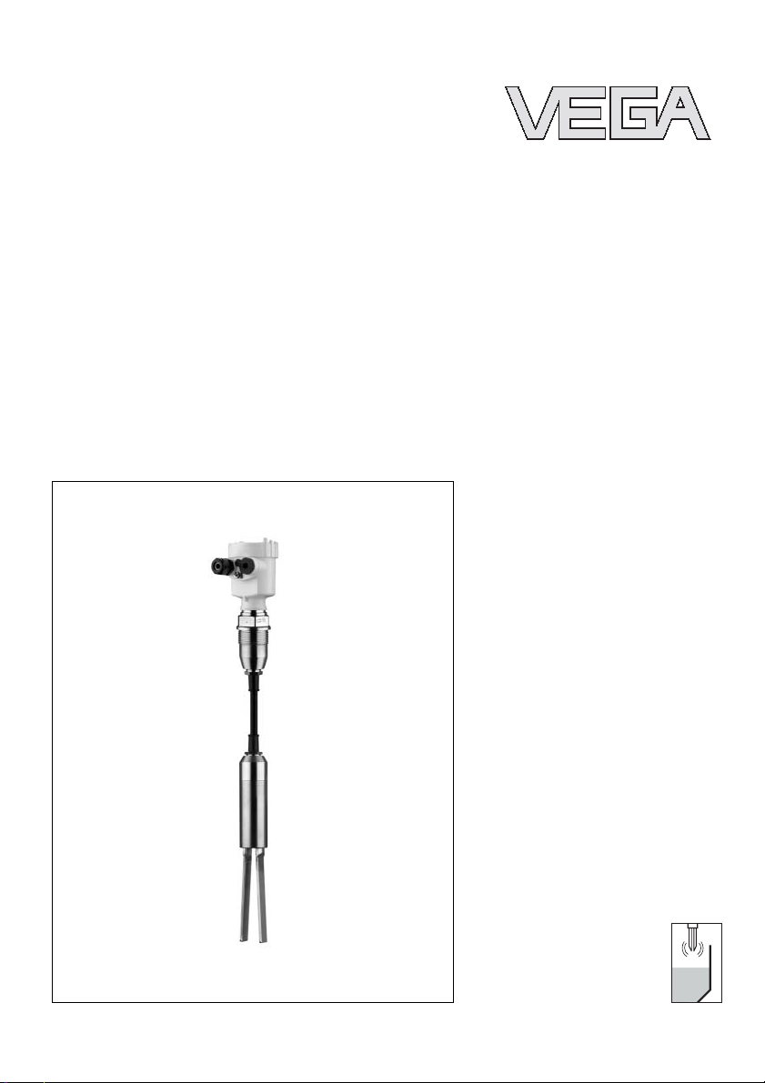
Operating Instructions
VEGAWAVE 62
Cable shortening set
Page 2

Contents
Contents
1 About this document
1.1 Function .............................
1.2 Target group ..........................
1.3 Symbolism used .......................
2 For your safety
2.1 Authorised personnel....................
2.2 Appropriate use........................
2.3 Warning about misuse ...................
2.4 Environmental instructions ................
3 Product description
3.1 Configuration..........................
3.2 Principle of operation ....................
3.3 Storage and transport ...................
4 Mounting
4.1 General instructions.....................
4.2 Mounting sequence .....................
5 Maintenance and fault rectification
5.1 Maintenance ..........................
5.2 Instrument repair .......................
3
3
3
4
4
4
4
5
5
5
6
7
17
17
6 Dismounting
6.1 Dismounting procedure ..................
6.2 Disposal .............................
7 Supplement
7.1 Technical data.........................
2 VEGAWAVE 62 - Cable shortening set
18
18
19
32361-EN-060822
Page 3

About this document
1 About this document
1.1 Function
This operating instructions manual has all the information you
need for quick mounting and setup of a replacement
component (cable shortening set). Please read this manual
before you start setup.
1.2 Target group
This operating instructions manual is directed to trained,
qualified personnel. The contents of this manual should be
made available to these personnel and put into practice by
them.
1.3 Symbolism used
Information, tip, note
This symbol indicates helpful additional information.
Caution: If this warning is ignored, faults or
malfunctions can result.
Warning: If this warning is ignored, injury to persons and/or
serious damage to the instrument can result.
Danger: If this warning is ignored, serious injury to persons
and/or destruction of the instrument can result.
Ex applications
This symbol indicates special instructions for Ex applications.
l List
The dot set in front indicates a list with no implied sequence.
à Action
This arrow indicates a single action.
1 Sequence
Numbers set in front indicate successive steps in a procedure.
32361-EN-060822
VEGAWAVE 62 - Cable shortening set 3
Page 4

For your safety
2 For your safety
2.1 Authorised personnel
All operations described in this operating instructions manual
must be carried out only by trained specialist personnel
authorised by the operator. For safety and warranty reasons,
any internal work on the instruments must be carried out only
by personnel authorised by the manufacturer.
2.2 Appropriate use
The cable shortening set is used to shorten VEGAWAVE
sensors in cable version (VEGAWAVE 62).
2.3 Warning about misuse
Inappropriate or incorrect use of the instrument can give rise to
application-specific hazards, e.g. vessel overfill or damage to
system components through incorrect mounting or adjustment.
2.4 Environmental instructions
Protection of the environment is one of our most important
duties. That is why we have introduced an environment
management system with the goal of continuously improving
company environmental protection. The environment management system is certified according to DIN EN ISO 14001.
Please help us fulfil this obligation by observing the environmental instructions in this manual:
l Chapter "Storage and transport"
l Chapter "Disposal"
4 VEGAWAVE 62 - Cable shortening set
32361-EN-060822
Page 5

3 Product description
3.1 Configuration
Product description
Scope of delivery
Area of application
Physical principle
Packaging
The scope of delivery encompasses:
l Cable shortening set
l Documentation
- this operating instructions manual
3.2 Principle of operation
The cable shortening set is a set of parts required to shorten a
VEGAWAVE 62.
The cable shortening set can be also used e.g. if the sensors
must be led through a narrow tube.
The cable shortening set must not be used if the concerned
sensor is used for solid detection in water.
The cable of the sensor consists of a suspension cable, the
electrical wires and an outer insulation.
3.3 Storage and transport
Your instrument was protected by packaging during transport.
Its capacity to handle normal loads during transport is assured
by a test according to DIN EN 24180.
The packaging of standard instruments consists of environ-
ment-friendly, recyclable cardboard. For special versions, PE
foam or PE foil is also used. Dispose of the packaging material
via specialised recycling companies.
Storage and transport temperature
32361-EN-060822
VEGAWAVE 62 - Cable shortening set 5
l Storage and transport temperature see "Supplement -
Technical data - Ambient conditions"
l Relative humidity 20 … 85 %
Page 6
Mounting
4 Mounting
4.1 General instructions
Necessary tools:
l Tape measure/Yardstick
l Cloth
l Marker (permanent)
l Bolt cutter
l Flat wrench SW 24
l Gaspipe pliers
l Skinning tools
l Cable cutter
l Wire cutter
l Crimping tool
l Allen wrench 2 mm
l Hot air blow-dryer
l Talcum/Mounting grease
Additionally:
l Bench vice with Aluminium or plastic braces
6 VEGAWAVE 62 - Cable shortening set
32361-EN-060822
Page 7

4.2 Mounting sequence
Mounting
1 2
7 6
Fig. 1: Cable shortening set for VEGAWAVE 62
1 Crimp connector yellow, 2 pcs., article no. 2.11444
2 Crimp connector red, 3 pcs., article no. 2.18710
3 Crimping sleeve blue 8 x 30 mm, 1 pce., article no. 1.243
4 Crimping sleeve black 3 x 55 mm, 1 pce., article no. 1.1207
5 O-rings 37 x 2 mm, 2 pcs., article no. 2.28878
6 Pins M4 x 6, 4 pcs., article no. 2.28894
7 Cable
clamp 12 x 20 mm, 1 pce., article
The numbers refer to the figures on the following pages.
no. 2.28876
3 4
5
Mounting
1 Interrupt the voltage supply of the sensor and remove
connection cable.
2 Dismount the sensor.
3 Clean the cable (9) of the sensor.
4 Determine new sensor length (L) with a tape measure
according to the illustration and mark with the marker.
You find information on the sensor length (L) in the
operating instructions manual of the sensor.
32361-EN-060822
VEGAWAVE 62 - Cable shortening set 7
Page 8

Mounting
145 mm
45
(5
/64")
L
neu
Fig. 2: Cut the cable with a bolt cutter
9 Cable
9
L
5 Cut the cable (9) with a bolt cutter approx. 145 mm
(approx. 5.7 in) above the new sensor length (L).
6 Clamp the upper part of the oscillator (19) in to the bench
vice.
149
Fig. 3: Unscrew pressure screw
9 Cable
14 Pressure screw
7 Remove pressure screw (14) with the flat spanner SW 24
so that the cable does not turn with the following
dismounting.
8 Clamp the lower part of the oscillator (below the screwed
separating position) into the bench vice.
Do not clamp on the fork tines
8 VEGAWAVE 62 - Cable shortening set
32361-EN-060822
Page 9

149 19
Fig. 4: Turn the vibrating element
9 Cable
14 Pressure screw
19 Upper part of the oscillator
Mounting
9 Loosen the upper part of the oscillator (19) with gaspipe
pliers and unscrew it. Both threaded connections are
secured with soluable screw retention lacquer.
Make sure that the cable (9) does not turn.
A B
Fig. 5: Uncompress the vibrating element carefully - cut the leads
AUpper part of the oscillator
BLower part of the oscillator
10 Uncompress the two parts (A and B) carefully.
Cut the leads directly on the clead pressing (see arrows)
with wire cutting pliers.
32361-EN-060822
VEGAWAVE 62 - Cable shortening set 9
Page 10

Mounting
Fig. 6: Pull the cable out the of upper part of the oscillator
9 Cable
10 Breaker plate
19 Upper part of the oscillator
11 Pull the cut cable (9) out of the upper part of the oscillator
(19).
Keep all parts for mounting.
9 1019
79 12 10
Fig. 7: Cut the suspension cable (12) with a bolt cutter
7 Cable clamp
9 Cable
10 Breaker plate
12 Suspension cable
12 Cut the suspension cable (12) with a bolt cutter and keep
the breaker plate (10) for mounting.
13 Clean the remaining sensor cable (9) from oil and grease
and rub it off with talcum.
The old cable crimping can be no longer used and must be
disposed accordingly.
10 VEGAWAVE 62 - Cable shortening set
32361-EN-060822
Page 11

Fig. 8: Shift the parts to the cable
6 Pins (4 pcs.)
7 Cable clamp
8 Mounting boss
9 Cable
10 Breaker plate
14 Pressure screw
15 Pressure ring
16 Rubber cover
17 Washer
18 Rubber rings (4 pcs.)
19 Upper part of the oscillator
Mounting
100 mm
15
(3
/16")
6181798 14 15 16 19 10 7
14 Shift the individual parts (14, 15, 16, 17, 18, 19) to the
cable according to drawing.
Make sure that the shoulder of the washer (17) points in the
direction of the pressure ring (15).
15 Remove the outer isolation of the cable on 100 mm (4 in)
length.
16 Shorten the suspension cable (12) with a bolt cutter by
70 mm (2.8 in)(remaining length: 30 mm/1.2 in).
32361-EN-060822
VEGAWAVE 62 - Cable shortening set 11
Page 12

Mounting
30mm
3
(1
/16")
Fig. 9: Shorten suspension cable - shift cable clamp
6 Pins
7 Cable clamp
10 Breaker plate
12 Suspension cable
17 Plug the breaker plate (10) on the bare suspension cable
(12) and lead the 4 wires (green, yellow, red, green-yellow)
separately through the outer holes of the breaker plate
(10).
Do not lead the fawn plastic cords (11) through the breaker
plate.
18 Shift the cable clamp (7) flush to the suspension cable (12).
When shifting, turn the cable clamp in the direction of the
cable drilling to avoid splicing the wire. The chamfered side
facilitates inserting the suspension cable.
19 Tighten the pins (6) constantly on all sides with an Allen
wrench 2 mm. The pins should be screwed in with the
same depth into the cable clamp (approx. 3 Nm / 2.2 lbf ft).
20 Cut the fawn plastic cords (11) as short as possible with a
wire cutter.
21 Remove the insulation of the screened green (GN) and
yellow (YE) wire
back the screen braiding and open it with a sharp object in
the rear section.
Make sure that the wires are not damaged.
100 mm
15
(3
/16")
on
a length of 60 mm (2.4 in). Slightly push
69 1210 7
12 VEGAWAVE 62 - Cable shortening set
32361-EN-060822
Page 13

RD
11
Fig. 10: Pull the wires out of the braiding
11 Plastic cords
GN Green
YE Yellow
Mounting
60mm
23
(2
/64")
GN
BK
YE
GN/YE
22 Pull the yellow and green wire backwards out of the screen
braiding.
23 Exchange O-rings (5), slightly grease thread and O-rings.
19 3 414
Fig. 11: Exchange O-ringe - prepare wires
3 Shrinking sleeve - blue
4 Crimping sleeve - black
5 O-rings
14 Pressure screw
19 Upper part of the oscillator
5 5
32361-EN-060822
VEGAWAVE 62 - Cable shortening set 13
Page 14

Mounting
24 Merge the screening of the wires (yellow) and (green) and
twist ist. Insulate the twisted screening with the black
crimping sleeve (4) according to the drawing. Shrink the
transition green-black-yellow in the isolated wire with the
blue crimping sleeve (3).
6
712
Fig. 12: Connect wires
6 Pins
7 Clamp terminal
12 Suspension cable
GN Green
BK Black
YE Yellow
RD red
GN/YE
Green-yellow
Fig. 13: Connect wires with crimping pliers
1 Crimp connection - yellow (2 pcs.)
2 Crimp connection - red (3 pcs.)
3 Shrinking sleeve - blue
14 Pressure screw
19 Upper part of the oscillator
GN/YE
GN
BK
YE
RD
GN/YE
GN
BK
YE
RD
25 Dismantle the wires on 5 mm (0.2 in) and connect with the
crimp connectors and crimping pliers according to drawing.
1 2314 19
26 Merge the parts of the vibrating element (A + B). Provide
the thread with screw retention lacquer. Make sure that you
do not squeeze any wires.
The cable must not turn.
32361-EN-060822
14 VEGAWAVE 62 - Cable shortening set
Page 15

14 A B
Fig. 14: Mount the vibrating element
14 Pressure screw
AUpper part of the oscillator
BLower part of the oscillator
Mounting
27 Mount the parts of the vibrating element. Clamp the lower
part of the oscillator (B) into the bench vice and turn only
the upper part of the oscillator (A). The cable must not turn.
28 Pull the cable (9) to the top and push the seal rings (18)
and the washer (17) in the upper part of the oscillator (19).
29 Shift the pressure screw (14) and the pressure ring (15) on
the rubber jacket (16).
181714 15 16 19
Fig. 15: Cable seal
14 Pressure screw
15 Pressure ring
16 Rubber jacket
17 Washer
18 Rubber rings
19 Upper part of the oscillator
30 Provide the pressure screw (14) with screw retention
lacquer and screw it into the upper part of the oscillator
(19).
31 Tighten the pressure screw (14) with the flat wrench SW 24
(approx. 6 Nm/4.4 lbf ft).
32 Check length of the sensor.
32361-EN-060822
VEGAWAVE 62 - Cable shortening set 15
Page 16

Mounting
33 Install the sensor.
34 Connect the sensor according to the operating instructions
manual of the sensor.
35 Check the correct switching function of the sensor.
16 VEGAWAVE 62 - Cable shortening set
32361-EN-060822
Page 17

Maintenance and fault rectification
5 Maintenance and fault rectification
5.1 Maintenance
If mounted correctly to the sensor, the cable shortening set is
maintenance-free. There are no restrictions of the specifications in the sensor documentation.
5.2 Instrument repair
Take note of the specifications in the sensor documentation.
32361-EN-060822
VEGAWAVE 62 - Cable shortening set 17
Page 18

Dismounting
6 Dismounting
6.1 Dismounting procedure
Note chapter "Mounting" and carry out the stated steps in
reverse order.
6.2 Disposal
The cable shortening set consists of materials which can be
recycled by specialised recycling companies.
Materials: see "Technical data"
Take note of the specifications in the sensor documentation.
18 VEGAWAVE 62 - Cable shortening set
32361-EN-060822
Page 19

Supplement
7 Supplement
7.1 Technical data
General data
Materials, wetted parts The resistance of the sensor does not change
by using the cable shortening set.
The materials used are stated in the operating
instructions manual of the sensor.
Sensor length 0.3 ... 80 m (1 ... 262 ft)
Approvals
The respective approvals of the sensor are not restricted by the correct use of the cable
shortening set.
32361-EN-060822
VEGAWAVE 62 - Cable shortening set 19
Page 20
VEGA Grieshaber KG
Am Hohenstein 113
77761 Schiltach
Germany
Phone +49 7836 50-0
Fax +49 7836 50-201
E-mail: info@de.vega.com
www.vega.com
ISO 9001
All statements concerning scope of delivery, application,
practical use and operating conditions of the sensors and
processing systems correspond to the information avail-
able at the time of printing.
© VEGA Grieshaber KG, Schiltach/Germany 2006
Subject to change without prior notice 32361-EN-060822
 Loading...