

Page 1
Supple
mentary instructions
VEGAVIB - External housing
Vibrati
on
Page 2

1 Conte
nts
Conten
1 About this document
2 For your safety
3 Product description
4 Mounting
5 Connect the sensor to the external housing
6 Setup
ts
1.1 Function . . . . . . . . . . . . . . . . . . . . . . . . . . . . . . . . .
1.2 Target group . . . . . . . . . . . . . . . . . . . . . . . . . . . . . .
1.3 Symbolism used . . . . . . . . . . . . . . . . . . . . . . . . . . .
2.1 Authorised personnel . . . . . . . . . . . . . . . . . . . . . . . .
2.2 Appropriate use . . . . . . . . . . . . . . . . . . . . . . . . . . . .
2.3 Safety instructions for Ex areas . . . . . . . . . . . . . . . .
2.4 Environmental instructions . . . . . . . . . . . . . . . . . . . .
3.1 Configuration . . . . . . . . . . . . . . . . . . . . . . . . . . . . . .
3.2 Principle of operation . . . . . . . . . . . . . . . . . . . . . . . .
3.3 Storage and transport . . . . . . . . . . . . . . . . . . . . . . .
4.1 General instructions . . . . . . . . . . . . . . . . . . . . . . . . .
4.2 Mounting preparations . . . . . . . . . . . . . . . . . . . . . . .
4.3 Mounting steps . . . . . . . . . . . . . . . . . . . . . . . . . . . .
4.4 Mounting - external housing (instrument housing) . . .
5.1 Preparing the connection . . . . . . . . . . . . . . . . . . . . .
5.2 Connection procedure . . . . . . . . . . . . . . . . . . . . . . .
6.1 Setup . . . . . . . . . . . . . . . . . . . . . . . . . . . . . . . . . . .
3
3
3
4
4
4
4
5
8
8
9
9
9
10
11
11
13
7 Maintain
7.1 Instrument repair . . . . . . . . . . . . . . . . . . . . . . . . . . .
8 Dismounting
8.1 Dismounting steps . . . . . . . . . . . . . . . . . . . . . . . . . .
8.2 Disposal . . . . . . . . . . . . . . . . . . . . . . . . . . . . . . . . .
9 Supplement
9.1 Technical data . . . . . . . . . . . . . . . . . . . . . . . . . . . .
9.2 Dimensions . . . . . . . . . . . . . . . . . . . . . . . . . . . . . . .
2 VEGAVIB - E
14
15
15
16
18
31086-EN-081119
xternal housing
Page 3
out this document
1 Ab
1 Abou
t this document
1.1 Function
This supplementary manual, together with the attached operating
instructions manual, has all the information you need for quick setup
and safe operation. Please read this manual before you start setup.
1.2 Target group
This operating instructions manual is directed to trained qualified
personnel. The contents of this manual should be made available to
these personnel and put into practice by them.
1.3 Symbolism used
Inform
ation, tip, note
This symbol indicates helpful additional information.
Cauti
on: If this warning is ignored, faults or malfunctions can
result.
Warning: If this warning is ignored, injury to persons and/or serious
damage to the instrument can result.
Danger: If this warning is ignored, serious injury to persons and/or
destruction of the instrument can result.
applications
Ex
This symbol indicates special instructions for Ex applications.
31086-EN-081119
VEGAVIB - E
l List
The dot set in front indicates a list with no implied sequence.
à Action
This arrow indicates a single action.
1 Sequence
Numbers set in front indicate successive steps in a procedure.
xternal housing 3
Page 4

2 For
your safety
or your safety
2 F
2.1 Authorised personnel
All operations described in this operating instructions manual must be
carried out only by trained specialist personnel authorised by the plant
operator.
During work on and with the device the required personal protection
equipment must always be worn.
2.2 Appropriate use
An external housing is part of a sensor.
2.3 Safety instructions for Ex areas
Please note the Ex-specific safety information for installation and
operation in Ex areas. These safety instructions are part of the
operating instructions manual and come with the Ex-approved
instruments.
2.4 Environmental instructions
Protection of the environment is one of our most important duties. That
is why we have introduced an environment management system with
the goal of continuously improving company environmental protection.
The environment management system is certified according to DIN
EN ISO 14001.
Please help us fulfil this obligation by observing the environmental
instructions in this manual:
l Chapter "Storage and transport"
l Chapter "Disposal"
4 VEGAVIB - E
31086-EN-081119
xternal housing
Page 5

3 Produc
t description
Scope of delivery
Components - external
housing with direct cable outlet
3 Produc
t description
3.1 Configuration
The scope of delivery encompasses:
l Level sensor with external housing
l Documentation
- a device operating instructions manual
- This supplementary instructions
- Ex specific safety instructions (with Ex versions), if necessary
further certificates
The instrument version "External housing" consists of the instrument
housing.
The instrument housing consists of the base element, the screwed
cover for the electronics or connection compartment and the housing
socket.
31086-EN-081119
VEGAVIB - E
xternal housing 5
Page 6
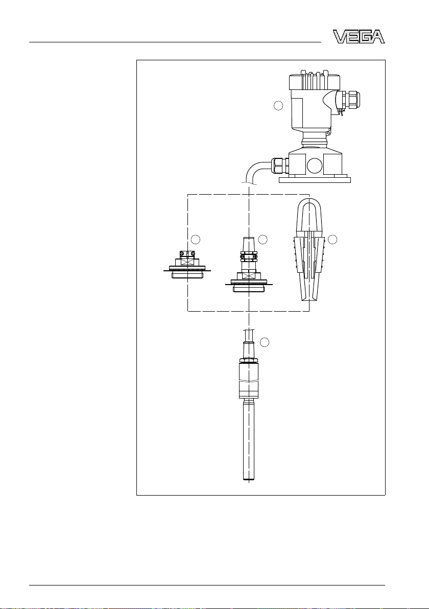
1
2 3 4
5
3 P roduc
t description
Fig. 1: Components
1 Instrument housing
2 Closing screw with cable gland (IP 20)
3 Closing screw with cable gland (IP 65)
4 Straining clamp
5 Vibrating rod
6 VEGAVIB - E
of the external housing for plics®devices
31086-EN-081119
xternal housing
Page 7

1
3
2
Components - instrument housing and external housing
3 Produc
e instrument version "External housing" and instrument housing
Th
t description
consists of a sensor housing and an instrument housing.
The metal sensor housing cannot be opened. The electrical
connection must be carried out on the instrument housing.
31086-EN-081119
VEGAVIB - E
Fig. 2: Instrument
1 Instrument housing
2 Sensor housing
3 Vibrating rod
The instrument housing consists of the base element, the screwed
cover for the electronics or connection compartment and the housing
socket.
xternal housing 7
housing and external housing
Page 8

A
B
1
2
3
4
3 P roduc
t description
Application area
Packaging
Storage and transport
temperature
Fig. 3: Components
A Sensor housing
B Instrument housing
1 Screwed cover
2 Base element
3 Housing socket
4 Wall mounting plate
of the external housing for plics®devices
3.2 Principle of operation
The external housing is suitable for the following plics sensors:
l VEGAVIB series 60
3.3 Storage and transport
Your instrument was protected by packaging during transport. Its
capacity to handle normal loads during transport is assured by a test
according to DIN EN 24180.
The packaging of standard instruments consists of environmentfriendly, recyclable cardboard. For special versions, PE foam or PE foil
is also used. Dispose of the packaging material via specialised
recycling companies.
l Storage and transport temperature see chapter "Supplement -
Technical data - Ambient conditions"
l Relative humidity 20 … 85 %
31086-EN-081119
8 VEGAVIB - E
xternal housing
Page 9

4 M
ounting
Tools
Mounting material
Wall mounting
4 Moun
ting
4.1 General instructions
In the following cases, we recommend using an instrument version
with external housing:
l if the standard housing is too big
l if strong vibrations can damage the electronics
In Ex
applications, only a housing with appropriate Ex approval must be
used.
4.2 Mounting preparations
The following tools are required for mounting:
l Allen key, size 4
l Fork wrench, wrench size 19
We recommend using further material when mounting the wall
mounting plate.
l 4 screws, depending on the mounting surface
4.3 Mounting steps
1 Mark the holes according to the following drilling template
2 Depending on the mounting surface, fasten the wall mounting
plate with 4 screws
31086-EN-081119
VEGAVIB - E
xternal housing 9
Page 10

90 mm (3.54")
R 3,5 mm
(0.14")
3mm
(0.12")
70 mm (2.76")
8 mm
(0.32")
93 mm (3.66")
110 mm (4.33")
4 M
ounting
Fig. 4: Drilling
Ti
p:
template - wall mounting plate
Mount the wall mounting plate so that the cable entry of the socket
housing points downward. Rain and condensation water can thus drain
off. The socket housing can be displaced by 180° to the wall mounting
plate.
Turn the cable gland of the instrument housing downward. The basic
body of the instrument housing can be turned by 330° without any
tools.
ning:
War
The four screws of the socket housing must only be hand-screwed. A
torque > 5 Nm (3.688 lbf ft) can damage the wall mounting plate.
4.4 Mounting - external housing (instrument
housing)
à Mount the sensor to the bottom, depending on the process fitting
Note:
When
mounting the sensor, note the instructions in the operating
instructions manual of the sensor.
31086-EN-081119
10 VEGAVIB - E
xternal housing
Page 11

1 2 3 4
5 Connec
t the sensor to the external housing
5 Conn
ect the sensor to the external housing
5.1 Preparing the connection
Follow the instructions in the operating instructions manual of the
sensor.
5.2 Connection procedure
Note:
Th
e metal sensor housing cannot be opened. The electrical
connection must be carried out on the instrument housing.
1 Insert the cable end through the cable entry on the external
housing (instrument housing)
Ti
p:
Only run the cable loosely. The connection cable can only be
separated on the external housing (instrument housing). If the sensor
should be dismounted, the connection cable must be free to take out
the sensor.
31086-EN-081119
VEGAVIB - E
Fig. 5: Connection
1 Red
2 Yellow
3 Black
4 Green
xternal housing 11
of the sensor in the socket housing
Page 12

ect the sensor to the external housing
5 Conn
2 Connec
t the cables to the terminals in the socket housing.
The cables are numbered and cannot be interchanged. The
ground cable (green/yellow) must be connected to the ground
screw.
3 Tighten the compression nut of the cable entry. The seal ring must
completely encircle the cable
The electrical connection of the electronics module is described in the
operating instructions manual of the sensor.
12 VEGAVIB - E
31086-EN-081119
xternal housing
Page 13

6 Setup
6.1 Setup
is carried out according to the operating instructions manual of
Setup
the respective sensor.
6 Setup
31086-EN-081119
VEGAVIB - E
xternal housing 13
Page 14

7 M
aintain
7 Maint
ain
7.1 Instrument repair
If a repair of the instrument is necessary, please proceed as follows:
You can download a return form (23 KB) from our Internet homepage
www.vega.com
form".
By doing this you help us carry out the repair quickly and without
having to call back for needed information.
l Print and fill out one form per instrument
l Clean the instrument and pack it damage-proof
l Attach the completed form and probably a safety data sheet to the
instrument
l Send the instrument to the address of the agency serving you. In
Germany, send it to the company headquarters in Schiltach.
under: "Downloads - Forms and certificates - Repair
14 VEGAVIB - E
31086-EN-081119
xternal housing
Page 15

8 Dismoun
ting
8 Dismou
nting
8.1 Dismounting steps
Take note of chapters "Mounting" and "Connect sensor to the external
housing" and carry out the listed steps in reverse order.
8.2 Disposal
The instrument consists of materials which can be recycled by
specialised recycling companies. We have purposely designed the
electronic modules to be easily separable. Mark the instrument as
scrap and dispose of it according to national government regulations
(e.g. in Germany according to electronic scrap ordinance).
Materials: see chapter "Technical data"
If you have no possibility to dispose of the old instrument
professionally, please contact us concerning return and disposal.
31086-EN-081119
VEGAVIB - E
xternal housing 15
Page 16

9 Suppl
ement
9 Supp
lement
9.1 Technical data
Technical data
Following you find all data deviating from the standard instrument. All other technical data are
specified in the operating instruction of the respective sensor.
General data
Material 316L corresponds to 1.4404 or 1.4435
Materials, non-wetted parts
- Sensor housing 316L
- External housing (instrument
housing)
- Housing socket plastic PBT (Polyester)
- Wall mounting plate plastic PBT (Polyester)
- Seal between housing socket and
wall mounting plate
- Seal between housing and housing
cover (instrument version)
- Ground terminal 316L
Weight
- External plastic housing 660 g (23 oz)
- Sensor housing 1100 g (38 oz)
Cable length to the external housing 2 m, 5 m, 10 m (6.562 ft, 16.41 ft, 32.81 ft)
plastic PBT (Polyester)
TPE (fixed connected)
Silicone
Process conditions
Process temperature Depending on the sensor
Ambient temperature on the sensor
housing
Ambient, storage and transport temperature on the instrument housing
16 VEGAVIB - E
-20 … +80 °C (-4 … +176 °F)
-40 … +80 °C (-40 … +176 °F)
31086-EN-081119
xternal housing
Page 17

plement
9 Sup
mechanical data
Electro
Cable entry/plug
1)
- Instrument housing l 1 x cable gland M20 x 1.5 (cable:
ø 6 … 12 mm), 2 x blind stopper M20 x 1.5
or:
l 1 x closing cap ½ NPT, 2 x blind stopper
½ NPT
or:
l 1 x plug (depending on the version), 2 x
blind plugs M20 x 1.5
- Housing socket l 1 x cable entry M20 x 1.5 (cable:
Spring-loaded terminals for wire cross-section up to 2.5 mm² (AWG 14)
Electrical protective measures
Protection
- Sensor housing IP 66/IP 67
- Instrument housing - Instrument
socket
ø 6 … 12 mm)
IP 66/IP 67
31086-EN-081119
VEGAVIB - E
1)
Depending on the version M12 x 1, according to DIN 43650, Harting, 7/
8" FF.
xternal housing 17
Page 18

90 mm (3.94")
110 mm (4.33")
~ 66 mm (2.6")
59 mm (2.32")
ø 10 mm
(0.39")
9 Suppl
9.2 D
ement
imensions
External housing - direct cable outlet
Fig. 6: External
18 VEGAVIB - E
housing with direct cable outlet to the vibrating element
31086-EN-081119
xternal housing
Page 19

sor housing and external housing (instrument housing)
90 mm (3.54")
110 mm (4.33")
ca.98 mm (3.86")
59 mm (2.32")
125 mm (4.92")
ø 5,5 mm
(0.22")
30 mm
(1.81")
~ 69 mm
(2.72")
ø 77 mm
(3.03")
112 mm (4.41")
M20x1,5/
½ NPT
Sen
9 Sup
plement
Fig. 7: Sensor
housing and external housing (instrument housing)
Housing versions - instrument housing
Fig. 8: Instrument
31086-EN-081119
VEGAVIB - E
housing - plastic housing
xternal housing 19
Page 20

VEGA Grieshaber KG
ISO 9001
Am Hohenstein 113
77761 Schiltach
Germany
Phone +49 7836 50-0
Fax +49 7836 50-201
E-mail: info@de.vega.com
www.vega.com
Printing date:
statements concerning scope of delivery, application,
All
practical use and operating conditions of the sensors and
processing systems correspond to the information avail-
able at the time of printing.
© VEGA Grieshaber KG, Schiltach/Germany 2008
Subject to change without prior notice 31086-EN-081119
 Loading...