

Page 1
Operating Instructions
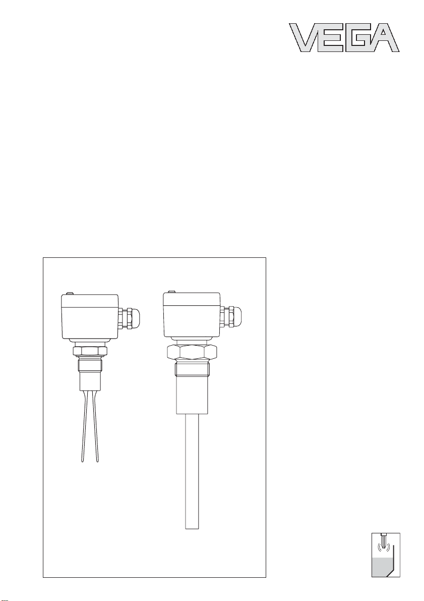
VEGAVIB
Page 2
Contents
Safety information .......................................................................... 2
Note Ex area .................................................................................. 2
1 Product description..................................................................... 3
1.1 Function and configuration .................................................... 3
1.2 Types and versions ................................................................ 3
1.3 Approvals .............................................................................. 4
1.4 Technical data ....................................................................... 5
1.5 Dimensions .......................................................................... 11
2 Mounting..................................................................................... 13
2.1 Mounting instructions .......................................................... 13
3 Electrical connection ................................................................ 16
3.1 Connection instructions VEGAVIB ....................................... 16
3.2 Wiring plan VEGAVIB .......................................................... 16
4 Set-up ......................................................................................... 18
4.1 VEGAVIB .............................................................................. 18
Contents
Safety information
Please read this manual carefully, and also take
note of country-specific installation standards
(e.g. the VDE regulations in Germany) as well as
all prevailing safety regulations and accident prevention rules.
For safety and warranty reasons, any internal
work in the instruments, apart from that involved
in normal installation and electrical connection,
must be carried out only by qualified VEGA personnel.
2 VEGAVIB
Note Ex area
Please note the attached safety instructions containing important information on installation and
operation in Ex areas.
These safety instructions are part of the operating instructions manual and come with the Ex
approved instruments.
Page 3

Product description
1 Product description
1.1 Function and configuration
VEGAVIB compact level switches are used for
level monitoring of powders and granules. The
vibrating level switches are energised
piezoelectrically and vibrate at their mechanical
frequency (VEGAVIB 31 approx. 210 Hz,
VEGAVIB 41 and 43 approx. 530 Hz, VEGAVIB
51, 52 and 53 approx. 350 Hz).
If the measured product reaches the sensor, the
vibrating amplitude is damped. An integrated
electronics detects this damping and triggers a
switching command.
VEGAVIB 31 is a tuning fork sensor and is suitable for unproblematic, fine-grained solids
> 100 g/l which do not cause buildup. Typical
products are gypsum, cement, chalk, fine granules, etc.
VEGAVIB series 40 and 50 vibrating level
switches can be used where levels of solids
with a density greater than approx. 20 g/l need
to be reliably detected. Due to the rod design, it
is almost impossible for material to build up or
get wedged in. This enables their use in foodstuffs and light solids such as e.g. packing
chips. Typical products are cement, gypsum,
chalk, flour, styrofoam, shredded paper, washing powder, plastic granules, down feathers,
packing chips etc. A pulsed actuating signal
causes the rod to begin vibrating again after
immersion and removes the measured product
from the vibrating rod.
Series 50 sensors are also suitable for the detection of solids in water.
1.2 Types and versions
VEGAVIB 31
Tuning fork compact level switch with fixed
installation length and mounting thread G 1 A.
The oscillator of VEGAVIB 31 has a floating
relay output.
VEGAVIB 41
Vibrating rod compact level switch with fixed
installation length and mounting thread G 1 A or
1 NPT. Three different oscillators are available
for different electrical outputs (contactless
electronic switch, relay or transistor). As an
option, a temperature adapter is available for
product temperatures exceeding 100°C.
VEGAVIB 43
Vibrating rod compact level switch with tube
extension up to max. 4 m. All other features are
the same as VEGAVIB 41. As an option, a lock
fitting is available for infinitely variable height
adjustment.
VEGAVIB 51
Vibrating rod compact level switch with fixed
installation length and mounting thread G 1½ A
or 1½ NPT. Four different oscillators are available for different electrical outputs (contactless
electronic switch, relay, transistor or two-wire
output). As an option, a temperature adapter is
available for product temperatures exceeding
100°C.
VEGAVIB 3
Page 4

Product description
VEGAVIB 52
Vibrating rod compact level switch with suspension cable extension up to max. 20 m. All other
features are the same as version VEGAVIB 51.
This version is suitable for temperatures up to
80°C.
VEGAVIB 53
Vibrating rod compact level switch with tube
extension up to max. 4 m. All other features are
the same as VEGAVIB 51. As an option, a lock
fitting is available for infinitely variable height
adjustment.
1.3 Approvals
VEGAVIB 51 Ex(S) and 53 Ex(S) are approved
for use in hazardous or dust-explosive areas of
zone 0, 20 and 2 in the scope of ATEX.
VEGAVIB 52 Ex is approved for use in hazardous areas of zone 0.
For such application, the corresponding official
documents (type approval certificate) must be
noted. They are delivered with the respective
instrument. Also note the relevant mounting and
operating instructions.
4 VEGAVIB
Page 5
Product description
1.4 Technical data
VEGAVIB 31
Housing
Housing material plastic PBT (Polyester)
Protection IP 66
Cable entry 2 x Pg 13.5
Terminals for max. 1.5 mm2 wire cross-section
Mechanical connection
Thread G 1 A of 1.4571
T uning fork
Material 1.4571 (StSt)
Lateral load max. 300 N perpendicular to the narrow fork side
Weight
VEGAVIB 31 approx. 0.8 kg
Ambient conditions
Ambient temperature on the housing -40°C … +70°C
Product temperature -40°C … +100°C (130°C for max. 30 minutes)
Storage and transport temperature -40°C … +70°C
Operating pressure
VEGAVIB 31 max. 25 bar
Product
Product density ≥0.1 g/cm³ (≥100 g/l)
Granulation size max. 6 mm
Oscillator - R (relay output)
Protection class I
Overvoltage category III
Immune to EMI > 10 V/m
Function
Integration time approx. 2 s
Frequency approx. 210 Hz
Signal lamp LED for switching point indication
Mode A/B switch
CE conformity
VEGAVIB 31 vibrating level switch meets the protective regulations of EMC (89/336/EWG) and
NSR (73/23/EWG). Conformity has been judged acc. to the following standards:
EMC Emission EN 50 081 - 1: 1992
Susceptibility EN 50 082 - 2: 1995
NSR EN 61 010 - 1: 1993
VEGAVIB 5
A - max. level detection
B - min. level detection
Page 6
Product description
VEGAVIB 41 and 43
Housing
Housing material plastic PBT (Polyester)
Protection IP 66
Cable entry 1 x Pg 13.5 (with oscillator R = 2 x Pg 13.5)
Terminals for max. 1.5 mm2 wire cross-section
Mechanical connection
Thread G 1 A or 1 NPT of 1.4571 (stst)
Lock fitting (VEGAVIB 43) G 1½ A of 1.4571 (stst)
Vibrating rod
Material 1.4571 (stst)
Lateral load 60 Nm or
Extension tube (VEGAVIB 43)
Materials 1.4571 (stst)
Length 350 mm … 4000 mm
Weight
VEGAVIB 41 approx. 0.8 kg
VEGAVIB 43 approx. 0.8 kg + extension tube (approx. 1 kg/m)
Ambient conditions
Ambient temperature on the housing -40°C … +70°C
Product temperature -40°C … +100°C
Storage and transport temperature -40°C … +70°C
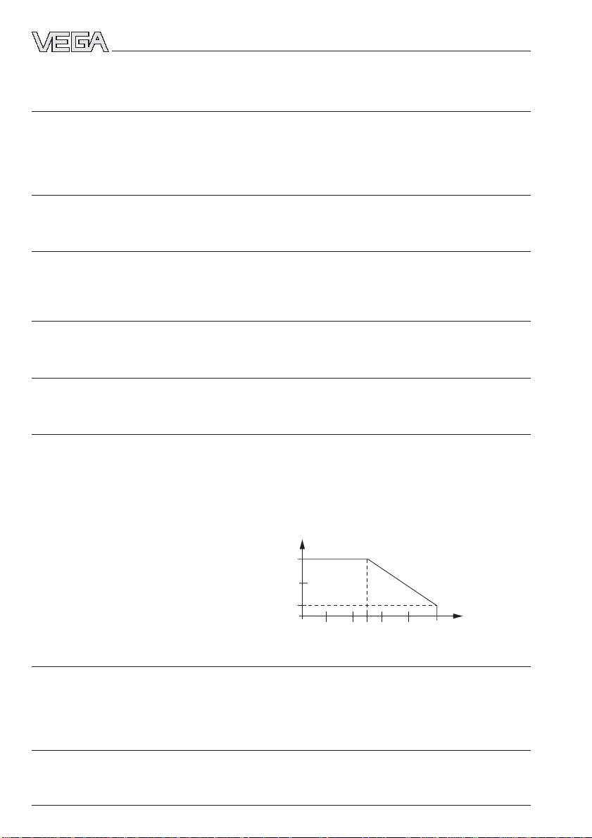
Product temperature with temperature
adapter of 1.4571 (option) -40°C … +150°C
max. 400 N on the rod end (VEGAVIB 41)
Permissible ambient
temperature
70˚C
60˚C
50˚C
100˚ 150˚C
110˚
120˚ 130˚
140˚
Product temperature with
temperature
adapter
Operating pressure
VEGAVIB 41, 43 max. 10 bar
VEGAVIB 43 with lock fitting
- version 1 unpressurised
- version 2 max. 4 bar
Product
Density ≥0.02 g/cm³ (≥ 20 g/l)
6 VEGAVIB
Page 7

Product description
Oscillators
Protection class
- oscillators C and R I
- oscillators T II
Overvoltage category III
Immune to EMI > 10 V/m
Function
Integration time approx. 2 s
Frequency approx. 530 Hz
Signal lamp LED for indication of the switching condition
Modes A/B switch
CE conformity
VEGAVIB 41 and 43 vibrating level switches meet the protective regulations of EMC
(89/336/EWG) and NSR (73/23/EWG). Conformity has been judged acc. to the following standards:
EMC Emission EN 50 081 - 1: 1992
Susceptibility EN 50 082 - 1: 1995
NSR EN 61 010 - 1: 1993
A - overfill or max. level detection
B - dry run protection or min. level detection
EN 50 082 - 2: 1995
version with relay output (R)
VEGAVIB 51, 52 and 53
Housing
Housing material plastic PBT (Polyester)
Protection IP 66
Cable entry 1 x Pg 13.5 (with oscillator R = 2 x Pg 13.5)
Terminals for max. 1.5 mm2 wire cross-section
Mechanical connection
Thread G 1½ A or 1½ NPT
Material
- VEGAVIB 51 and 52 plastic PBT, 1.4301 (StSt)
- VEGAVIB 53 1.4301 (StSt)
Lock fitting (VEGAVIB 53) G 2 A of 1.4301 (StSt)
Vibrating rod
Material 1.4301 (StSt)
Lateral load 60 Nm or
VEGAVIB 7
400 N on the rod end (VEGAVIB 51)
Page 8

Product description
Suspension cable (VEGA VIB 52)
Material PUR
Max. tensile load 6000 N
Length
- PBT mounting boss 600 mm … 10 m
- steel mounting boss 600 mm … 20 m
Extension tube (VEGAVIB 53)
Material 1.4301 (StSt)
Length 350 mm … 4000 m
Weight
VEGAVIB 51 approx. 1.7 kg
VEGAVIB 52 approx. 1.3 kg (with 2 m) + suspension cable
(approx. 0.15 kg/m)
VEGAVIB 53 approx. 2.0 kg + extension tube (approx. 2.2 kg/m)
Ambient conditions
Ambient temperature on the housing -40°C … +70°C
Product temperature
- VEGAVIB 51 and 53 -40°C … +100°C
- VEGAVIB 52 -40°C … +80°C
Storage and transport temperature -40°C … +70°C
Product temperature with temperature
adapter of 1.4571 (option)
(VEGAVIB 51 and 53 with
1.4301 mounting boss) -40°C … +150°C
Permissible
ambient temperature
70˚C
60˚C
50˚C
100˚ 150˚C
110˚
120˚ 130˚
140˚
Product temperature with
temperature
adapter
Operating pressure
VEGAVIB 51 and 53 max. 10 bar
VEGAVIB 52 max. 6 bar
VEGAVIB 53 with lock fitting unpressurised or vacuum
VEGAVIB 51 with PBT mounting boss max. 6 bar
Product
Density ≥ 20 g/l
8 VEGAVIB
Page 9

Product description
Oscillators
Protection class
- oscillators C and R I
- oscillators T and Z II
Overvoltage category III
Immune to EMI > 10 V/m
Function
Integration time approx. 2 s
Frequency approx. 350 Hz
Signal lamp
- oscillators C, R and T LED for indication of the switching condition
- oscillator Z LED lights when vibrating rod is immersed
Modes
- oscillators C, R and T A/B switch
A - overfill protection or max. level detection
B - dry run protection or min. level detection
- oscillator Z definition via signal conditioning instrument
Approvals
ATEX II 1G EEx ia IIC T6
ATEX II 1/2G EEx ia IIC T6
ATEX II 2G EEx ia IIC T6
ATEX II 1/2D IP 65 T
Note safety instructions for Ex applications
In hazardous areas you have to note the respective regulations, conformity and type approval
certificates of the sensors and power supply units. The sensors must only be operated on intrinsically safe circuits. The permissible electrical values are stated in the certificate.
CE conformity
VEGAVIB 51, 52 and 53 vibrating level switches meet the protective regulations of EMC
(89/336/EWG) and NSR (73/23/EWG). Conformity has been judged acc. to the following standards:
EMC Emission EN 50 081 - 1: 1992
Susceptibility EN 50 082 - 1: 1992
EN 50 082 - 2: 1995
version with relay output (R)
NSR EN 61 010 - 1: 1993
VEGAVIB 9
Page 10

Product description
Oscillators
C - Contactless (VIB E40 C, E50 C), VEGA VIB 41, 43, 51, 52, 53
Power supply 20 … 250 V AC, 50/60 Hz
Output contactless electronic switch
Domestic current requirement < 5 mA (via the load circuit)
Load current min. 10 mA, max. 400 mA (max. 4 A up to 40 ms)
The max. permissible ambient temperature is 60°C with a load current exceeding 300 mA.
R - Relay output (VIB E30 R, E40 R, E50 R), VEGAVIB 31, 41, 43, 51, 52, 53
Power supply 20 … 250 V AC, 50/60 Hz; 20 … 72 V DC
Power consumption approx. 1 … 8 VA, max. 1.5 W
Output relay output
Relay data:
- contact floating spdt
- contact material AgCdO and Au plated
- turn-on voltage min. 10 mV
- switching current min. 10 µA
- breaking capacitance max. 500 VA, 54 W
T - T ransistor output (VIB E40 T, E50 T), VEGA VIB 41, 43, 51, 52, 53
Power supply 10 … 55 V DC
Power consumption max. 0.5 W
Output floating transistor output
Load current max. 400 mA (output - overload resistant and
Voltage loss max. 1 V
Turn-on voltage max. 55 V DC
Blocking current < 10 µA
20 … 250 V DC
(the max. permissible ambient temperature decreases linearly from 70°C to 50°C between
60 V DC and 72 V DC)
max. 250 V AC, 250 V DC
max. 3 A AC, 1 A DC
NPN/PNP wirable
permanently short-circuit proof)
Z - T wo-wire output (VIB E50 Z, E50 Z Ex), VEGA VIB 51, 52, 53
Power supply 12 … 36 V DC
Output two-wire output
Current consumption
- vibrating rod free 8 mA
- vibrating rod immersed 16 mA
Suitable signal conditioning instruments VEGALOG 571
10 VEGAVIB
(power supply via VEGATOR signal conditioning
instrument)
VEGATOR 425 Ex F, 525 F, 534 Ex, 536 Ex,
537 Ex, 636 Ex, 825 Ex
Page 11

Product description
1.5 Dimensions
VEGAVIB 31
VEGAVIB 41
VEGAVIB 43
80x110
95
20
148
100
G 1 A
Ø 29
~30
SW 41
95
140
20
100
80x110
~30
SW 41
G 1 A
Ø 14
Housing Lock fitting unpressurised
60
15
330°
rotable
20
20
SW 41
SW 60
G 1½ A
80x110
95
20
L (min. 300, max. 4.000 mm)
100
~30
SW 41
G 1 A
Ø 29
Ø 14
PG 13,5
Temperature adapter (1.4571)
57
VEGAVIB 11
41
Page 12

Product description
VEGAVIB 51 VEGAVIB 52 VEGAVIB 53
95
22
253 (Kunststoff), 238 (V2A)
160
80x110
Ø 18
~30
G 1½ A
Ø 43
SW 60
PG 13,5
80x110
95
22
L (min. 600, max. 20.000)
332
160
Ø 18
~30
G 1½ A
Ø 43
SW 60
PG 13,5
80x110
95
22
G 1½ A
Ø 43
L (min. 300, max. 4.000)
160
Ø 18
~30
PG 13,5
SW 60
Housing Temperature adapter (1.4301) Lock fitting
SW 60
60
15
330°
rotable
104
∅57
80
105
12 VEGAVIB
SW 75
G 2 A
Page 13

Mounting
2 Mounting
2.1 Mounting instructions
VEGAVIB
Generally, the instruments can be mounted in
any position. The instrument must be mounted
so that the measuring system (vibrating rod) is
at the height of the requested switching point.
VEGAVIB 31, however, from below the vessel
bottom. Installation will vary depending on the
various measured products and the requirements on the measurement. You should give
consideration to the following points.
Lateral load
Make sure that the vibrating element is not
subjected to lateral forces. Mount the instrument
at a location in the vessel where no adverse
conditions, e.g. caused by stirrers, filling openings etc. can occur. This applies mainly to
instrument types with cable or extension tube
(see fig. 2.1). The surfaces of the tuning fork of
VEGAVIB 31 should be parallel to the product
movement.
Stirrers
Through the action of stirrers or similar devices,
the level switches can be subjected to strong
lateral forces. For this reason, do not use an
overly long extension tube for VEGAVIB 43 and
VEGAVIB 53, but check if it is possible to mount
instead a VEGAVIB 41 or VEGAVIB 51 level
switch on the side of the vessel in horizontal
position.
Filling opening
Mount the instrument in such a way that the
vibrating element does not protrude directly into
the filling stream. If such a mounting location is
necessary, install a suitable protective sheet
above or in front of the vibrating element, e.g.
L80 x 8 DIN 1028 (see fig. 2.2 a). Mounting acc.
to Fig. 2.2 has proven successful for measuring
abrasive solids. A product cornice grows on the
concave protective sheet and keeps it from
being abraded.
Horizontal installation
To achieve a very precise switching point,
VEGAVIB can be mounted horizontally. However
if the switching point can have a tolerance of a
few centimetres, we recommend mounting the
instruments downwardly inclined (approx. 20°)
to avoid buildup (see fig. 2.2). Mount VEGAVIB
31 in such a way that the surfaces of the tuning
fork are vertical.
a.
Fig. 2.1
Dimensions
b.
20%
The dimensions of the vibrating rod or the tuning fork should not be modified. Any change will
destroy the instrument.
Fig. 2.2
VEGAVIB 13
Page 14

Mounting
Handling
The vibrating level switch is a measuring instrument and must be treated accordingly. Bending
the vibrating element will destroy the instrument.
Lock fitting
Lock fittings are available for VEGAVIB 43 and
VEGAVIB 53 for infinitely variable height adjustment. Be aware that VEGAVIB 53 level switches
in conjunction with a lock fitting must not be
used in pressurized vessels. VEGAVIB 43 can
be used in vessels with up to 4 bar pressure.
Tensile load
When using the cable version, make sure that
the max. permissible tensile load of 6000 N is
not exceeded. This can occur mainly with very
heavy solids and large measuring lengths.
Buildup
With VEGAVIB 31, the surfaces of the tuning
fork should be vertical in order to reduce
buildup. The orientation of a tuning fork is
marked on the hexagon of VEGAVIB. With it you
can check the position of the tuning fork. When
the hexagon touches the seal, the thread can
still be turned by approx. half a turn. This is
sufficient to reach the recommended installation
position.
If the granulation size of the solid is larger than
the min. distance between the tuning fork
blades (8 mm), product particles can wedge
themselves in the tuning fork and trigger a
malfunction. In this case, series 40 or 50 vibrating level switches should be used.
Pressure
When there is gauge pressure or underpressure
in the vessel, the mounting boss must be sealed
on the thread. Cover the thread with teflon tape,
hemp or a similar material or use a sufficiently
resistant seal ring.
Fig. 2.3
Material cone
When planning the location of the vibrating rod
in the vessel, be aware that in solids, material
cones can form which can change the switching point. We recommend selecting an installation location where the vibrating rod detects an
average value of the material cone. The mounting location of the vibrating rod must take the
location of the filling and emptying apertures of
the vessel into account. To compensate measurement errors caused by the material cone in
cylindrical tanks, the vibrating rod must be
mounted at a distance of d/6 from the vessel
wall. Here, a min. distance of approx. 40 cm
must be maintained (see fig. 2.4).
Moisture
Turn the cable entry of the instrument downwards (after installation) to avoid moisture ingress. For this purpose, the housing can be
rotated by approx. 330°. With vertically installed
instruments, loop the cable to the instrument
housing downwards so that rain or condensation water can drain off (see fig. 2.3).
14 VEGAVIB
Page 15

Mounting
Filling and emptying centered
Filling
d
6
d
Filling centered, emptying lateral
Filling
Emptying
d
6
d
Emptying
3
6
d
d
1
1 Emptying aperture
2 Filling aperture
2
3 VEGAVIB
Fig. 2.4
VEGAVIB 15
Page 16

3 Electrical connection
Electrical connection
3.1 Connection instructions VEGAVIB
Note
Switch off power supply before starting connection work.
The electrical connection must be carried out
according to the installed oscillator. Connect
supply voltage according to the wiring diagrams
on the following pages.
As a rule, connect VEGAVIB to vessel ground
(PA) or in plastic vessels, to nearest ground
potential. For this purpose, a thread (screw M4 x
5) is provided on the side on the hexagon of the
mounting boss. This connection serves to drain
off electrostatic charges.
In dust-Ex applications or applications acc. to
CENELEC, the PA terminal (on the hexagon of
the mounting boss) must be connected to the
potential equalisation line.
1
9
8
3.2 Wiring plan VEGAVIB
Non-contact electronic switch
(VIB E40 C, E50 C)
123
AC L1 N Vessel ground
DC + –
or
DC – +
Power supply:
20 … 250 V AC, 50/60 Hz; 20 … 250 V DC (for
further information see Technical data)
For direct control of relays, contactors, magnet
valves, warning lights, horns, etc. Instrument
must not be operated without connected load
(switching in series), as the oscillator can be
destroyed when connected directly to mains.
Not suitable for connection to low voltage PLC
inputs.
2
The domestic current is temporarily lowered
3
below 1 mA after switching off the load so that
the contactors, whose load current is less than
4
the permanently flowing domestic current of the
electronics, are reliably switched off.
5
6
7
1 Housing cover
2 Signal lamp (LED)
3 Terminals
4 A/B switch
5 Potentiometer
6 Instrument housing
7 Cable entry (Pg 13.5)
8 Oscillator
9 Type label oscillator
16 VEGAVIB
Page 17

Electrical connection
Floating relay output (VIB E30 R, E40 R,
E50 R)
+
-
L1
N
2
1
3 4
5
6
Relay output
Power supply
Power supply:
20 … 250 V AC, 50/60 Hz; 20 … 72 V DC (for
further information see Technical data)
For direct switching of external voltage sources
to relays, contactors, magnet valves, warning
lights, horns, etc.
Tw o-wire output (VIB E50 Z)
For connection to a VEGATOR signal conditional instrument (only with VEGAVIB 51, 52 and
53)
Power supply via the connected VEGATOR
signal conditioning instrument (12 … 36 V DC)
(for further information see Technical data)
Floating transistor output
(VIB E40 T, E50 T)
-
2
1
3 4+5
Power supply : 10 … 55 V DC
(for further information see the following connection examples as well as Technical data)
Connection examples
+- +
1
+
NPN action PNP action
-
2
3 4 5 1
-
2
3 4 5
+
-
As a rule, the signal lamp in the housing lights
when the vibrating rod is immersed, independent of the mode set in the signal conditioning
instrument.
Note the operating instructions manual of the
The transistor switches the supply voltage of the
oscillator to the binary input of a PLC or to an
electrical load. By connecting the consumer
(load) in different ways, PNP or NPN action can
be preset.
signal conditioning instrument. Suitable signal
conditioning instruments under Technical data.
-
+
123
VEGATOR
signal conditioning
instrument
VEGAVIB 17
Page 18

4 Set-up
Set-up
4.1 VEGAVIB
Adjustment elements
The diode (2) can be checked with closed
housing. To adjust VEGAVIB, loosen the four
screws on the upper side of the housing with a
screwdriver and remove the housing cover.
The oscillators allow the following settings:
• A/B mode, only with oscillators C, R and T;
with oscillator Z: switch over via the signal
conditioning instrument
• sensitivity setting with potentiometer (not with
VEGAVIB 31)
With the A/B switch (4) you can change the
switching condition of the contactless electronic
switch (C), the relay output (R) or the transistor
output (T) . You can set the required mode acc.
to the "Function chart". A - max. level detection
or overfill protection, B - min. level detection or
dry run protection.
With oscillator Z the A/B mode can be switched
via the signal conditioning instrument. Note the
setup of the signal conditioning instrument.
With the potentiometer (5) you can change the
switching sensitivity and adapt it to the density
of the product. This is necessary for detection of
extremely light or heavy products. Turn the
potentiometer anticlockwise to make the vibrating probe more sensitive. Normally, a modification of the default setting will only be necessary
with extremely light products.
For most products, it is not necessary to change
the setting of the preset potentiometer (default
setting of the potentiometer = 5).
To modify the integration time, you have to use
oscillator Z in conjunction with a suitable signal
conditioning instrument (VEGATOR 534, 536,
537 and 636).
The instrument version for detection of solids in
water is adapted for use in water and cannot be
used for normal level detection. Adjustment of
the settings of the instrument is identical.
2
1
1 Type label
2 Signal lamp (LED)
3 Terminals
4 A/B switch
5 Potentiometer (not with VEGAVIB 31)
3
4
5
With adhesive products, it might be necessary
to turn the potentiometer clockwise to achieve a
better oscillation.
18 VEGAVIB
Page 19

Set-up
Function chart
The following chart provides an overview of the switching conditions depending on the adjusted
mode and level.
Level Switching condition Signal Current Signal
Mode A
Mode B
Failure of the supply voltage
Mode
A / B any Transistor
VIB E40 / VIB E30 / VIB E40 / lamp consumpt. lamp
50 C 40 / 50 R 50 T VEGAVIB E50 Z VEGAVIB
21
Switch Relay
closed energised
21
Switch Relay deopen energised
21
Switch Relay
closed energised
21
Switch Relay deopen energised
21
Switch Relay deopen energised
Transistor
64 5
conducts appr. 8 mA
Transistor
64 5
blocks appr. 16 mA
Transistor
64 5
conducts appr. 16 mA
Transistor
64 5
blocks appr. 8 mA
64 5
blocks 0 mA
VEGAVIB 19
Page 20

VEGA Grieshaber KG
Am Hohenstein 113
77761 Schiltach
Germany
Phone (07836) 50-0
Fax (07836) 50-201
E-Mail info@de.vega.com
www.vega.com
ISO 9001
All statements concerning scope of delivery, practical use and operating
conditions of the sensors and processing systems correspond to the
latest information at the time of printing.
Technical data subject to alterations
17496-EN-030718
 Loading...