

Page 1
V E G A I N D U S T R I E S L I M I T E D
VegaAIS AtoN Station
Installation and Operation Manual
Available models
Options
Product Version
Software version:
Manual version:
Date released:
Status:
VegaAIS Product Manual
VAIS-1S Type 1 Standard Model
VAIS-1E Type 1 Extended Model
VAIS-3S Type 3 Standard Model
VAIS-3E Type 3 Extended Model
Unidirectional Current / Voltage sensor
Bidirectional Current / Voltage sensor
1
1.0
1.0.8
5th June 2015
Released
Page 2
User Manual VegaAIS AtoN Station © Vega Industries Ltd, June 2015
Manual revision history
Manual Version Released Description of Change Software version VegaAIS Serial number
1.0.0 Sept 2014
1.0.1 Dec 2014
1.0.2 Dec 2014
1.0.3 Dec 2014
1.0.4 Dec 2014
1.0.5 Jan 2015
1.0.6 Jan 2015
1.0.7 May 2015
1.0.8 June 2015
• Pre-release for BSH review
• Added voltage reference for power consumption
figures
• Added Manual Configuration section
• Added description of battery protection feature
• Initial Release
• Added General Warning section
• Add reference to DOC
• Added information about external fuses and
disconnect devices
• Added Type 3 power consumption figures
1.0 21000000+
1.0 21000000+
1.0 21000000+
1.0 21000000+
1.1 21000000+
Caution: This device generates potentially harmful levels of radio frequency radiation. Please
read section 1.1.5 General Warnings before operating this device.
VEGA INDUSTRIES LIMITED
21 Heriot Drive, Porirua 5022, New Zealand
Tel: +64 4 238 0200; Fax: +64 4 237 4392
Product Warranty
Vega warrants that all products supplied are free from labour and material defects, and will repair or replace (at its option) the whole or
any part of the products found to be faulty. The standard warranty is valid for 12 months from the date of dispatch. Vega is not to be
liable for any charge beyond the point of delivery, including installation, alignment or testing. To claim under warranty the product must
be returned to the Vega factory in New Zealand at the users expense.
Legal Notice
Information in this document is subject to change without notice. Vega Industries Ltd. makes no warranty of any kind with regards to
this material, including but not limited to, the implied warranties of merchantability and fitness for purpose. Vega Industries Ltd. shall not
be liable for errors contained herein or for incidental or consequential damages in connection with the use of this material. No part of
E-mail: sales@vega.co.nz Web: http://www.vega.co.nz
VegaAIS AtoN Station Page 2 of 54 VegaAIS V1.0.8
Page 3

User Manual VegaAIS AtoN Station © Vega Industries Ltd, June 2015
this document may be photocopied, reproduced, or translated to another language without prior written consent of Vega Industries Ltd.
The Vega logo is a registered trademark of Vega Industries Ltd. All other trademarks belong to their respective proprietors.
VegaAIS AtoN Station Page 3 of 54 VegaAIS V1.0.8
Page 4

User Manual VegaAIS AtoN Station © Vega Industries Ltd, June 2015
Table of Contents
SECTION 1 OVERVIEW OF THE VEGA AIS ATON STATION .............................................. 6
1.1 Introduction .......................................................................................................................... 6
1.1.1 Model Range ..................................................................................................................... 6
1.1.2 Additional Factory Options ................................................................................................ 6
1.1.3 Approvals & Certification ................................................................................................... 6
1.1.4 Quality Assurance ............................................................................................................. 6
1.1.5 General Warnings ............................................................................................................. 6
1.2 Supported AIS Messages .................................................................................................... 8
1.2.1 Aids-to-Navigation Report ................................................................................................. 8
1.2.2 Monitoring Report .............................................................................................................. 8
1.2.3 Meteorological / Hydrographic Report ............................................................................... 8
1.3 Mechanical Description ........................................................................................................ 9
1.3.1 Construction ...................................................................................................................... 9
1.3.2 Sealing ............................................................................................................................ 10
1.3.3 Installation ....................................................................................................................... 11
1.4 Electrical ............................................................................................................................ 14
1.4.1 Electrical Connections ..................................................................................................... 14
1.4.1.1 Power Supply / Ground ............................................................................................... 16
1.4.1.2 Beacon Connector RS232 Rx and Tx ......................................................................... 16
1.4.1.3 Sync Connection ......................................................................................................... 16
1.4.1.4 AtoN On Digital Input .................................................................................................. 16
1.4.1.5 AtoN Fail Digital Input ................................................................................................. 16
1.4.1.6 RACON Fail Digital Input ............................................................................................ 16
1.4.1.7 RACON Present Digital Input ...................................................................................... 16
1.4.1.8 Isolated ADC Inputs (A & B)........................................................................................ 16
1.4.1.9 Isolated Digital Inputs (1-8) ......................................................................................... 17
1.4.1.10 Boot Input ................................................................................................................... 17
1.4.1.11 Weather Station Connector RS232 Rx and Tx ............................................................ 17
1.4.1.12 Weather Station Connector RS485-A, RS485-B ......................................................... 17
1.4.1.13 Weather Station Connector RS422-A, RS422-B ......................................................... 17
1.4.2 Current Sensor Connections ........................................................................................... 17
1.5 Power Consumption .......................................................................................................... 19
1.5.1 Type 1 VegaAIS .............................................................................................................. 19
1.5.2 Type 3 VegaAIS .............................................................................................................. 19
1.5.3 Battery Protection Feature ............................................................................................... 19
1.6 Error Code Reporting......................................................................................................... 21
SECTION 2 CONFIGURATION ............................................................................................. 22
2.1 VegaAIS Configuration Tool Introduction ........................................................................... 22
2.1.1 Installation ....................................................................................................................... 22
2.1.2 Default Configuration ....................................................................................................... 22
2.1.3 Connection to VegaAIS Unit ............................................................................................ 22
2.2 Configuration Tool Instructions .......................................................................................... 23
2.2.1 Creating a Configuration ................................................................................................. 23
2.2.1.1 Load Configuration from File ....................................................................................... 23
2.2.1.2 Load Configuration from VegaAIS Device ................................................................... 24
2.2.1.3 Load from Template (Quick Setup) ............................................................................. 25
2.2.1.4 Create New Configuration ........................................................................................... 26
2.2.2 Editing a Configuration .................................................................................................... 33
2.2.3 Programming a Configuration .......................................................................................... 34
VegaAIS AtoN Station Page 4 of 54 VegaAIS V1.0.8
Page 5

User Manual VegaAIS AtoN Station © Vega Industries Ltd, June 2015
2.3 Manual Configuration......................................................................................................... 36
2.3.1 Standard Sentences ........................................................................................................ 36
2.3.1.1 Binary Message Configuration .................................................................................... 36
2.3.2 Proprietary Sentences ..................................................................................................... 36
2.3.2.1 Hardware Configuration .............................................................................................. 37
2.3.2.2 Configuration Query .................................................................................................... 37
2.3.2.3 Configuration Reset .................................................................................................... 38
2.3.2.4 Beacon Monitoring Configuration ................................................................................ 38
2.3.2.5 RACON Monitoring Configuration ............................................................................... 38
2.3.2.6 Monitoring Report Configuration ................................................................................. 39
2.3.2.7 Monitoring Report Parameter Mapping ....................................................................... 39
2.3.2.8 Meteorological/Hydrographic Report Configuration ..................................................... 40
2.3.2.9 GPS Sync Configuration ............................................................................................. 40
SECTION 3 PROGRAMMING ............................................................................................... 41
SECTION 4 ATON AND RACON STATUS MONITORING ................................................... 42
4.1 Fixed Status Bits ................................................................................................................ 42
4.2 AtoN Status Monitoring ...................................................................................................... 42
4.3 RACON Status Monitoring ................................................................................................. 43
SECTION 5 MONITORING REPORTS.................................................................................. 44
5.1 VegaWeb Monitoring Report.............................................................................................. 44
5.2 IALA GLA Monitoring Report ............................................................................................. 45
SECTION 6 METEOROLOGICAL / HYDROGRAPHIC REPORTS ....................................... 47
6.1 Supported NMEA Weather Sentences ............................................................................... 47
6.2 Met/Hydro Message Format .............................................................................................. 47
SECTION 7 MAINTENANCE ................................................................................................ 49
7.1 Maintenance Cleaning ....................................................................................................... 49
7.2 Periodic Inspection Check ................................................................................................. 49
User Notes .................................................................................................................................... 50
Appendix A Specifications .................................................................................................. 51
Appendix B Declaration of Conformance .......................................................................... 53
Appendix C VEGA AIS Product Codes ............................................................................... 54
VegaAIS AtoN Station Page 5 of 54 VegaAIS V1.0.8
Page 6
User Manual VegaAIS AtoN Station © Vega Industries Ltd, June 2015
Model
Description
SECTION 1 OVERVIEW OF THE VEGA AIS ATON STATION
1.1
Introduction
The VegaAIS AtoN Station is a Type 1 or Type 3 AIS AtoN Station as described in IALA A-126
Edition 1.5, June 2011. The VegaAIS AtoN Station will provide broadcast information of the
location and operation of the Aid to Navigation to vessels and base stations receiving AIS
messages.
The VegaAIS unit can also transmit AtoN monitoring information and also relay Meteorological /
Hydrographic information as part of the overall AIS system.
1.1.1 Model Range
The following model range is available:
Type 1 Standard Model Transmit only, FATDMA, no extended I/O
Type 1 Extended Model Transmit only, FATDMA, extended I/O
Type 3 Standard Model1 Transmit and Receive, FATDMA and RATDMA, no
extended I/O
Type 3 Extended Model1 Transmit and Receive, FATDMA and RATDMA, extended
I/O
Notes:
1. Type 3 models not yet available.
The extended inputs supported by the Extended models are:
• eight isolated digital inputs
• two isolated analogue inputs
• three additional inputs (optionally isolated) for RACON presence and failure monitoring
1.1.2 Additional Factory Options
Additional Factory options for the VegaAIS AtoN Station:
• Weather Station Port
• Unidirectional Current / Voltage Sensor
• Bidirectional Current / Voltage Sensor
• RACON Port (for Standard model only)
• Collision Detection and Reporting (Type 3 models only)
Each of these options is described more fully later in this manual.
1.1.3 Approvals & Certification
The VegaAIS type 1 unit has been tested to IEC 62320-2 by German Federal Maritime and
Hydrographic Agency BSH. Certificate number: BSH/4542/002/4322515/15.
Vega Industries declares that this product is in compliance with the essential requirements and
other provisions of the R&TTE directive 1999/5/EC.
See Appendix B Declaration of Conformance for a copy of the Declaration of
Conformance.
1.1.4 Quality Assurance
All manufacture and assembly is performed under ISO9001 certification.
1.1.5 General Warnings
VegaAIS AtoN Station Page 6 of 54 VegaAIS V1.0.8
Page 7

User Manual VegaAIS AtoN Station © Vega Industries Ltd, June 2015
RF Emissions:
Caution: This device generates and radiates electromagnetic energy. This device must be
installed and operated according to the instructions contained in this manual. Failure to do so can
result in product malfunction and / or exposure to potentially harmful levels of radio frequency
radiation.
Caution: Never operate this device unless it is connected to a VHF antenna.
The system has a Maximum Permissible Exposure (MPE) radius of 1m from the antenna. This
has been determined assuming the maximum power of the transponder and using a standard
monopole VHF antenna with a maximum gain of 3dBi and termination impedance of 50 ohms.
When installing the antenna and operating the equipment consider the following,
• Higher gain VHF antennas will require a larger MPE radius
• Do not operate the unit when anyone is within the MPE radius of the antenna
• The antenna should not be collocated or operated in conjunction with any other transmitting
antenna.
VegaAIS AtoN Station Page 7 of 54 VegaAIS V1.0.8
Page 8

User Manual VegaAIS AtoN Station © Vega Industries Ltd, June 2015
1.2
Supported AIS Messages
The VegaAIS AtoN Station supports the following messages as defined in ITU-R M.1371-4:
• Message 21 - Aids-to-Navigation report
• Message 6 - Addressed binary message
• Message 8 - Binary broadcast message
Message 21 is the primary message for AIS AtoN systems as it is the standardised AtoN status
message. The VegaAIS unit complies with the message 21 definition as described in the ITU-R
specification above and the IALA Recommendation A-126 Ed 1.5.
The VegaAIS unit can also transmit monitoring data, either addressed (message 6) or broadcast
(message 8). Two data formats are currently supported, a proprietary format used to log data to
the VegaWeb server, and the IALA GLA format as described in Annex C, Table 4 of the IALA A126 Recommendation.
The VegaAIS unit can also transmit Meteorological / Hydrographic data. This data is only
transmitted as a broadcast message (message 8) and the data format conforms to the IMO
SN.1/Circ.289 (2 June 2010) Table 1.1 recommendation.
1.2.1 Aids-to-Navigation Report
As described above, the Aids-to-navigation report complies with the message 21 definition in ITUR M.1371-4 and IALA Recommendation A-126 Ed 1.5.
The AtoN status bits in message 21 may be generated in a number of ways:
• Fixed status bits
• Light on/off determined from digital input
• Light on/off determined from serial signal (Vega beacons only)
• Light on/off determined by beacon current
• Light ok/fail determined by digital input
• Light ok/fail determined by serial signal (Vega beacons only)
• Light ok/fail determined by light detected off when it should be on
• RACON presence determined from digital input
• RACON failure determined from digital input
These options can be selected using the VegaAIS Configuration Tool. AtoN and RACON status
monitoring is more fully described in SECTION 4 ATON AND RACON STATUS MONITORING.
1.2.2 Monitoring Report
Monitoring reports are described in SECTION 5 MONITORING REPORTS.
1.2.3 Meteorological / Hydrographic Report
Meteorological/Hydrographic reports are described in SECTION 6 METEOROLOGICAL /
HYDROGRAPHIC REPORTS.
VegaAIS AtoN Station Page 8 of 54 VegaAIS V1.0.8
Page 9
User Manual VegaAIS AtoN Station © Vega Industries Ltd, June 2015
1.3
Mechanical Description
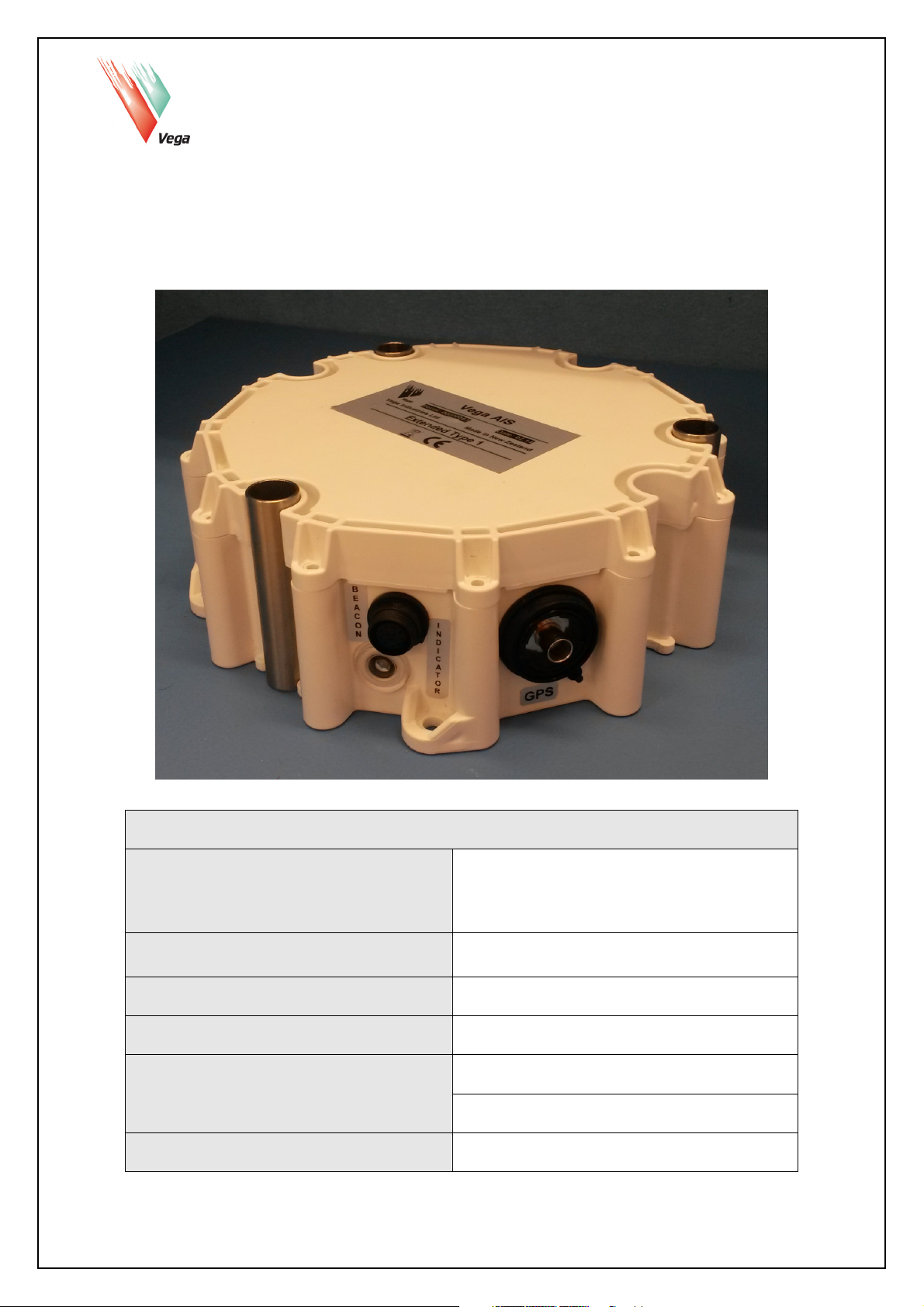
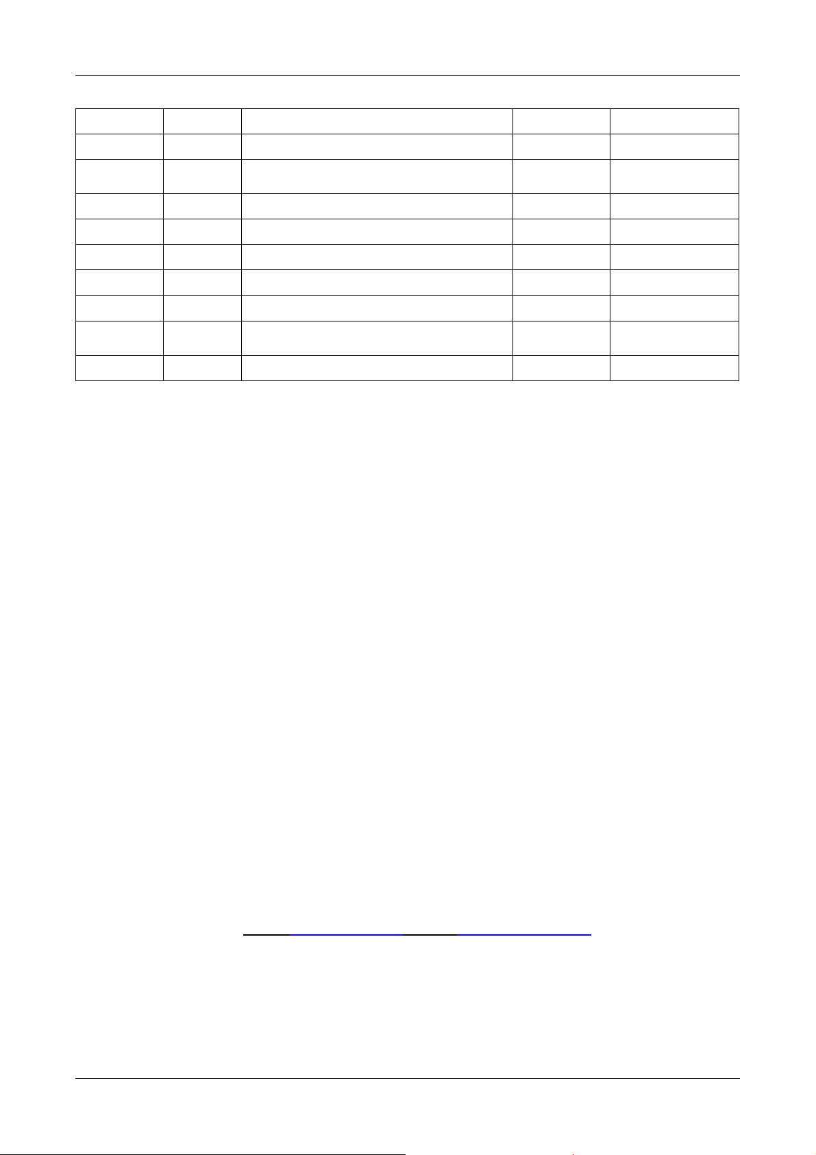
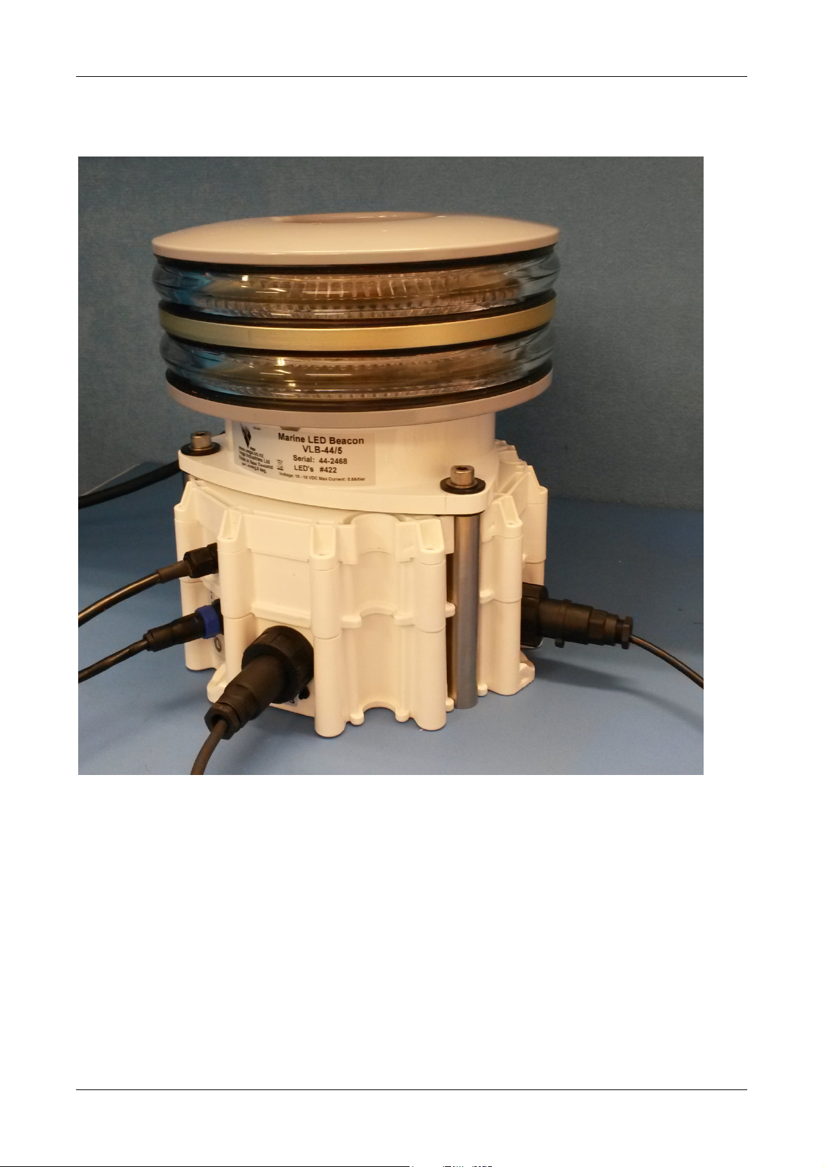
1.3.1 Construction
The standard VegaAIS unit consists of a main enclosure and a lid. Where the current / voltage
sensor option is required, another enclosure is sandwiched between the main enclosure and the
lid.
The main enclosure which is common to all models houses the AIS engine including VHF
transmitter and receiver (type3 units only) as well as the AtoN monitoring electronics. This unit is
not user serviceable and, to minimise the risk of compromising the sealing, should not be opened.
Lid
Main Enclosure
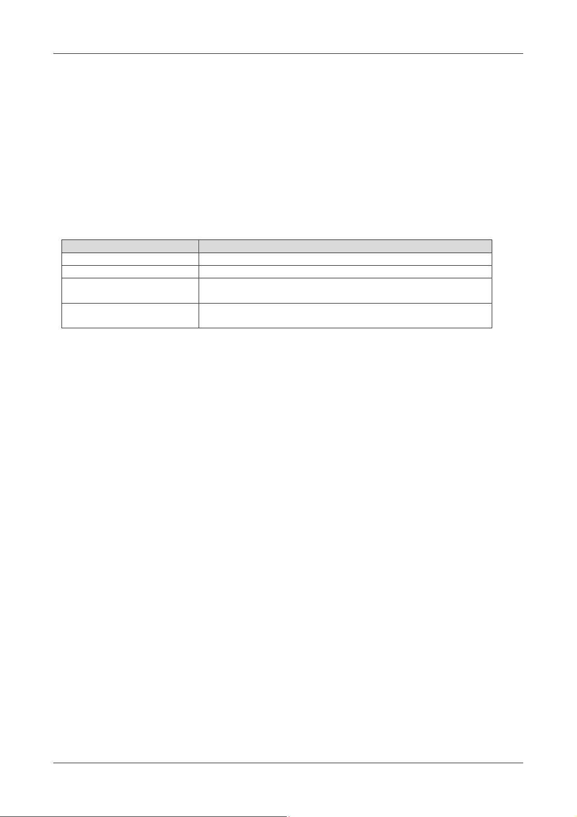
The current / voltage sensor unit is mounted on top of the main unit and houses the screw
connections for the current / voltage sensor(s) as well as the glands for passing cables in and out
of this unit.
Current Sensor
Enclosure
The lid fits onto either the main unit or the current sensor unit depending on whether the current
sensor unit is fitted. The lid is assembled using self-tapping fasteners into the enclosure. Take
care not to over torque these screws when assembling the lid.
VegaAIS AtoN Station Page 9 of 54 VegaAIS V1.0.8
Page 10
User Manual VegaAIS AtoN Station © Vega Industries Ltd, June 2015
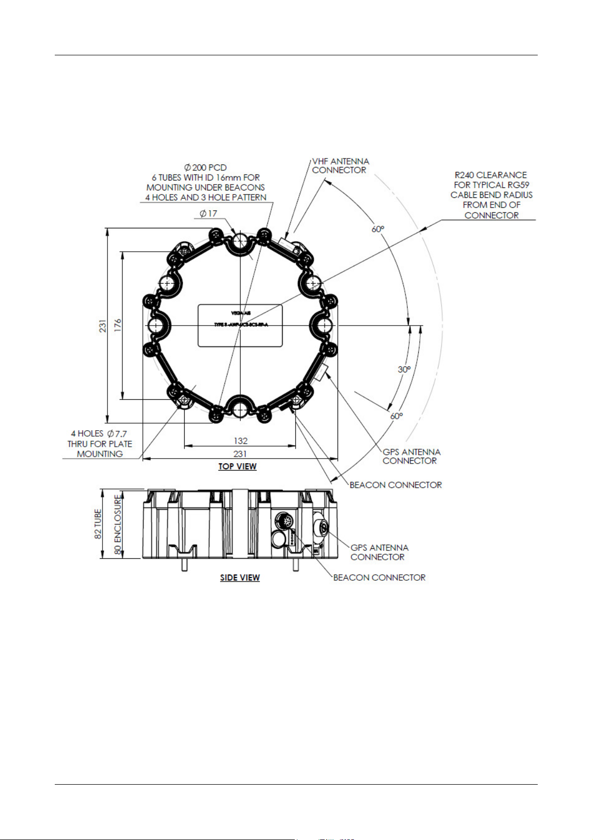
The VegaAIS unit is designed to be sandwiched under an AtoN that is mounted on the standard
three or four hole mount on a 200mm PCD – as shown below.
If this mounting option is chosen, the stainless steel anti-crush tubes must be fitted to prevent the
VegaAIS enclosure from bearing the weight of the AtoN.
Alternately, the VegaAIS unit may be secured using the four mounting lugs on the main enclosure.
1.3.2 Sealing
The VegaAIS unit is sealed to the IP68 standard against the ingress of moisture, dust, insects and
other environmental contaminants. Because the VegaAIS unit does not need to be opened for
configuration, these seals can remain undisturbed for extended periods. If the current sensor unit
is opened to connect the current sensor terminals, do not let any water accumulate in this
compartment and take care to ensure the sealing O ring is correctly located in its O ring groove
when reassembling.
VegaAIS AtoN Station Page 10 of 54 VegaAIS V1.0.8
Page 11
User Manual VegaAIS AtoN Station © Vega Industries Ltd, June 2015
1.3.3 Installation
As mentioned above, the VegaAIS unit may be mounted under an AtoN using a three or four hole
mount on a 200mm PCD. Alternately the VegaAIS unit may be mounted using the four mounting
lugs on the base of the main enclosure.
Installation details are shown below.
If an AtoN is mounted on top of the VegaAIS unit, the stainless steel anti-crush tubes must be fitted
to prevent the VegaAIS unit from bearing the weight of the AtoN. As can be seen in the schematic
above, these tubes sit proud of the top of the enclosure and therefore bear the weight and
clamping forces of the AtoN.
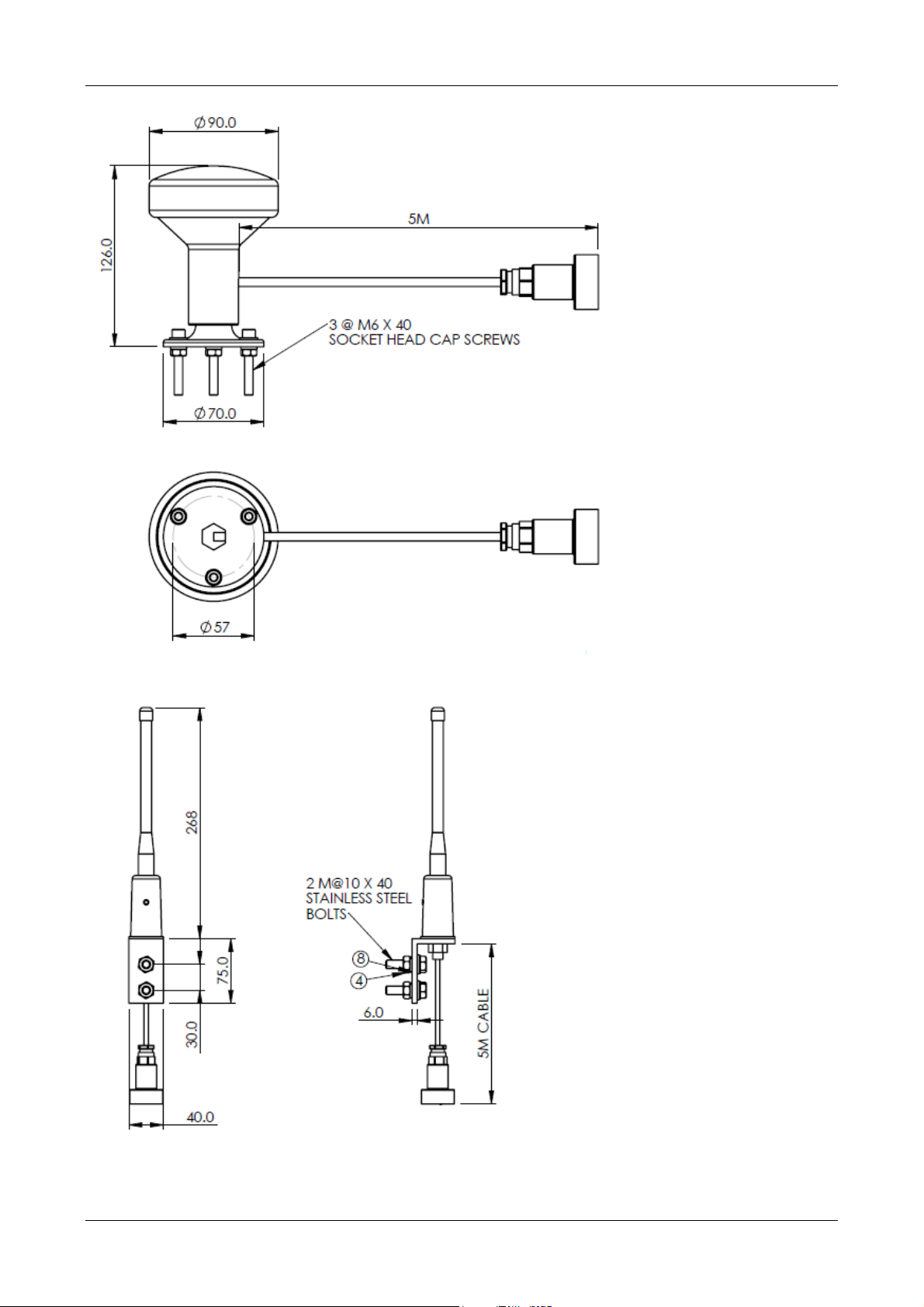
The VegaAIS unit is supplied with both a GPS and a VHF antenna – installation schematics shown
below. These may be mounted on any convenient mounting point with the following provisions.
• The GPS antenna must be mounted such that it has a clear view of the sky. Any
obstruction of this view will diminish the performance of the GPS antenna.
• The VHF antenna should be mounted as high as possible and as far away as possible
from any metallic structure that may interfere with transmission and reception.
• Both antennas should be mounted with the main axis of the antenna vertical.
VegaAIS AtoN Station Page 11 of 54 VegaAIS V1.0.8
Page 12
User Manual VegaAIS AtoN Station © Vega Industries Ltd, June 2015
GPS Antenna Installation Schematic
VHF Antenna Installation Schematic
VegaAIS AtoN Station Page 12 of 54 VegaAIS V1.0.8
Page 13

User Manual VegaAIS AtoN Station © Vega Industries Ltd, June 2015
Both the GPS and VHF antennas are potted at the antenna and use the IP68 Bulgin Buccanneer
connector to connect to the VegaAIS unit. The connection locations are shown on the VegaAIS
installation schematic – these connection locations are also labelled on the VegaAIS unit.
Furthermore, the polarities of these two connectors are reversed meaning that it is impossible to
connect either antenna to the wrong location.
The other electrical connections are described in the Electrical section below.
VegaAIS AtoN Station Page 13 of 54 VegaAIS V1.0.8
Page 14
User Manual VegaAIS AtoN Station © Vega Industries Ltd, June 2015
Pin Colour
Description
1.4
Electrical
1.4.1 Electrical Connections
The number of electrical connections will depend on the VegaAIS model and options selected.
All units will have a RF antenna and a GPS antenna connection. The installation of these
antennas and their electrical connections are detailed in the Installation section above.
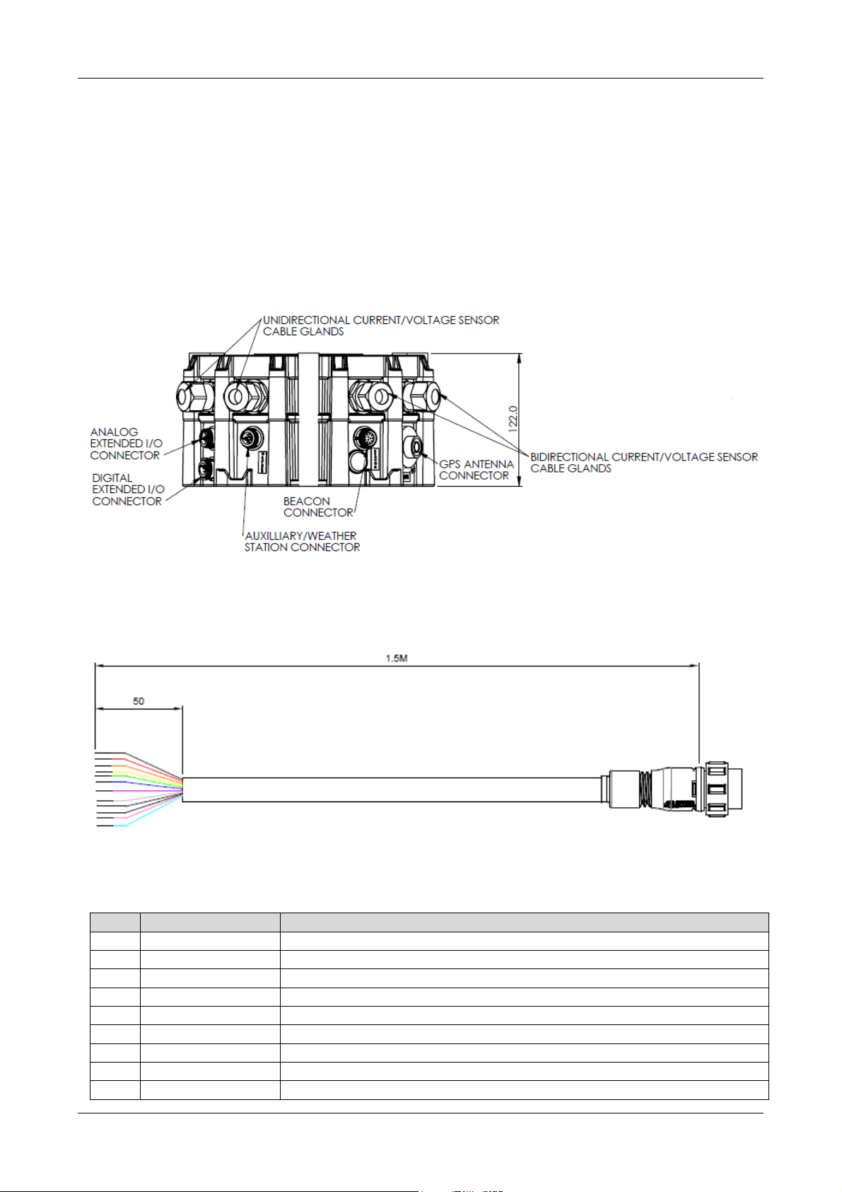
There are four other possible connectors on the main VegaAIS unit; these are called the Beacon
Connector, the Weather Station Connector, the Analogue Extended I/O Connector and the Digital
Extended I/O Connector. The position of these connectors is shown on the schematic below.
All connectors are labelled on the VegaAIS unit and all connectors have different pin counts and
polarity to ensure they cannot be incorrectly connected. Cables are supplied for all installed
connections. The supplied cables are 1.5m long with unterminated ends - as shown below.
All units will have at least the Beacon Connector as this contains the serial interface for the
configuration tool. The pinout for the Beacon Connector is shown below.
1 Red Positive Supply
2 Black Ground
3 Orange No connection
4 Violet RS232 Rx – for config tool or connection to Vega smart beacon
5 Yellow RS232 Tx – for config tool or connection to Vega smart beacon
6 Green Sync connection
7 Brown No connection
8 Grey AtoN on digital input
9 White AtoN fail digital input
VegaAIS AtoN Station Page 14 of 54 VegaAIS V1.0.8
Page 15
User Manual VegaAIS AtoN Station © Vega Industries Ltd, June 2015
Pin Colour
Description
Pin Colour
Description
Pin Colour
Description
10 Blue No connection
11 Cyan No connection
12 Pink No connection
Beacon Cable Pinout
The Extended models will also be supplied with the Analogue Extended I/O Connector and the
Digital Extended I/O Connector and cables. The pinouts for these cables is given below.
1 Red Positive Supply
2 Black Ground
3 Orange No connection
4 Yellow RACON fail digital input
5 Green RACON presence digital input
6 Blue RACON common
7 Violet Isolated ADC B negative
8 Grey Isolated ADC B positive
9 Brown Isolated ADC A negative
10 Pink Isolated ADC A positive
Analogue Extended I/O Cable Pinout
Note that the Analogue Extended I/O connector includes the RACON inputs. Therefore, if the
RACON port option is selected for a VegaAIS standard mode, this connector will be fitted.
1 Brown Isolated digital input #1
2 Red Isolated digital input #2
3 Orange Isolated digital input #3
4 Yellow Isolated digital input #4
5 Green Common
6 Blue Common
7 Violet Isolated digital input #5
8 Grey Isolated digital input #6
9 White Isolated digital input #7
10 Black Isolated digital input #8
Digital Extended I/O Cable Pinout
If the Weather Station Port option is required then the Weather Station connection and cable will
be supplied. The pinout for this cable is given below.
1 Red Positive Supply
2 Black Ground
3 Orange Boot
4 Violet RS232 Rx – for weather station comms
5 Yellow RS232 Tx – for weather station comms
6 Green Sync connection
7 Blue RS232 ground
8 Grey No connection
9 White RS485-B
10 Brown RS485-A
11 Pink RS422-A
12 Cyan RS422-B
Weather Station Cable Pinout
VegaAIS AtoN Station Page 15 of 54 VegaAIS V1.0.8
Page 16

User Manual VegaAIS AtoN Station © Vega Industries Ltd, June 2015
These connections are described below:
1.4.1.1 Power Supply / Ground
This input provides power for the VegaAIS unit. Voltage range: 10 – 36VDC. Max current: 2A.
The VegaAIS unit can be powered from the Beacon Connector, the Analogue Extended I/O
Connector, the Weather Station Connector or the Unidirectional Current sensor. The VegaAIS unit
will automatically switch between these inputs depending on which input is powered.
Do not connect directly to a battery or power supply - an external fuse must be fitted between the
battery/power supply and the VegaAIS unit.
When powering the VegaAIS unit via the Beacon connector, the Analogue Extended I/O connector
or the Weather Station connector, this fuse should be 2.5A. If it is required to disconnect the
VegaAIS unit from the supply, just disconnect the appropriate connector that is supplying the
power. If more than one connector is supplying power (e.g. a backup supply) then remove all
connectors supplying power to the VegaAIS unit. If necessary, mark the cables to be
disconnected to completely disconnect the supply so it may be done by an untrained operator.
When powering the VegaAIS unit via the unidirectional current sensor, the value of the fuse
depends on the load being powered from the unidirectional current sensor. This fuse should never
exceed 40A.
When powering the VegaAIS unit via the unidirectional current sensor, a readily accessible
disconnect device should be incorporated in the external power supply so that the VegaAIS unit
may be disconnected when required.
1.4.1.2 Beacon Connector RS232 Rx and Tx
This is the RS232 connection used for VegaAIS configuration and (optionally) for communications
with a Vega smart beacon. Baud rate 38400bps, 8 bits data, no parity, one stop bit.
1.4.1.3 Sync Connection
This output provides a GPS sync pulse for flash synchronisation of AtoNs. The active sync pulse
can be configured to be high or low. Flash character length is also configurable.
1.4.1.4 AtoN On Digital Input
This input can be used to indicate if the AtoN is on or off for use in the Message 21 AtoN Status
byte. This input has a configurable pull-up or pull-down resistor. The active polarity is also
configurable. Active polarity in this case means the polarity when the AtoN is on.
1.4.1.5 AtoN Fail Digital Input
This input can be used to indicate if the AtoN has failed for use in the Message 21 AtoN Status
byte. This input has a configurable pull-up or pull-down resistor. The active polarity is also
configurable. Active polarity in this case means the polarity when the AtoN has failed.
1.4.1.6 RACON Fail Digital Input
This input can be used to indicate if the RACON has failed for use in the Message 21 AtoN Status
byte. This input has a configurable pull-up or pull-down resistor. The active polarity is also
configurable. Active polarity in this case means the polarity when the RACON has failed.
1.4.1.7 RACON Present Digital Input
This input can be used to indicate if a RACON is present or not for use in the Message 21 AtoN
Status byte. This input has a configurable pull-up or pull-down resistor. The active polarity is also
configurable. Active polarity in this case means the polarity when the RACON is present.
1.4.1.8 Isolated ADC Inputs (A & B)
These are two isolated, differential analogue inputs. Input range 0 – 36VDC. 12 bit ADC.
VegaAIS AtoN Station Page 16 of 54 VegaAIS V1.0.8
Page 17
User Manual VegaAIS AtoN Station © Vega Industries Ltd, June 2015
1.4.1.9 Isolated Digital Inputs (1-8)
These are eight isolated digital inputs referenced to an isolated common. These may be
individually configured to be a current source or sink.
1.4.1.10 Boot Input
This pin is used when reprogramming the VegaAIS unit in bootstrap mode. Not currently
supported. This input must be left unconnected.
1.4.1.11 Weather Station Connector RS232 Rx and Tx
This is the RS232 connection used for Weather Station communications. Baud rate 38400bps, 8
bits data, no parity, one stop bit.
1.4.1.12 Weather Station Connector RS485-A, RS485-B
This is the RS485 connection used for Weather Station communications. Baud rate 38400bps, 8
bits data, no parity, one stop bit.
1.4.1.13 Weather Station Connector RS422-A, RS422-B
This is the RS422 connection used for Weather Station communications. Baud rate 38400bps, 8
bits data, no parity, one stop bit.
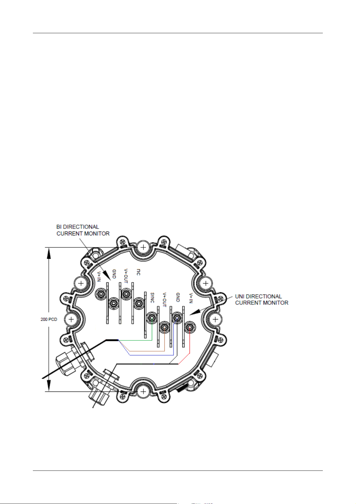
1.4.2 Current Sensor Connections
If the optional current sensor unit is fitted, then removing the VegaAIS lid will expose the current
sensor terminals as shown below.
The diagram above shows the wiring where only the unidirectional current sensor is fitted and is
used to measure beacon current. Power is brought in through one gland (red and black wires) and
out to the beacon through the other (brown, blue and green). Many other combinations are
possible using up to four glands to route cables.
VegaAIS AtoN Station Page 17 of 54 VegaAIS V1.0.8
Page 18

User Manual VegaAIS AtoN Station © Vega Industries Ltd, June 2015
Stud
Description
The current sensors are high side current sensors. Each current sensor has the following
connections:
V+ IN Positive supply in
GND Ground
V+ OUT Positive supply out
SYNC Sync connection – see 1.4.1.3
[only uni-directional sensor]
The current sensor connections are M5 studs intended for ring crimp terminals. Two cable glands
sizes are available: M16: cable sizes 4.5-9mm OD, M20: cable sizes 7.5-13.2mm OD. Up to four
glands can be fitted as required.
Whether using the uni-directional or bi-directional current sensor, a fuse must be fitted between the
battery and the current sensor connection. The value of the fuse will depend on the expected
current but should not exceed 40A.
VegaAIS AtoN Station Page 18 of 54 VegaAIS V1.0.8
Page 19

User Manual VegaAIS AtoN Station © Vega Industries Ltd, June 2015
1.5
Power Consumption
The VegaAIS AtoN Station is intended to be deployed on solar powered installations. As such it
has been designed to minimise power consumption as far as possible.
The actual power consumption achieved will depend on a number of factors including message
transmission rate, number of messages supported, quality of GPS signal, weather station support
and monitoring configuration.
The VegaAIS unit is designed to spend as much time as possible in a low power sleep state. It
only wakes up when it has some task to perform – for example sending a message. Therefore
high message transmission rates and/or a high number of messages will increase power
consumption.
The VegaAIS system needs to achieve a GPS lock prior to each transmission. If the GPS antenna
is unable to get a clear view of the sky, the time taken to achieve GPS lock will take longer and the
VegaAIS unit will spend more time on than it would otherwise need to – increasing power
consumption.
The VegaAIS unit periodically samples its inputs to provide data for Message 21 and monitoring
reports. Normally the sample time is very brief and does not have a big impact on power
consumption. However, if the unit is configured to measure beacon current on a flashing beacon,
the sample period needs to be as long as the flash character. This will increase the power
consumption.
If the VegaAIS unit is configured to communicate with a weather station, it will wake up periodically
to sample the inputs from that weather station. This will increase power consumption.
Type 3 units will consume more power as they have RF receivers and need to be awake a lot more
of the time to receive incoming message to maintain their AIS slot map.
1.5.1 Type 1 VegaAIS
For a basic type 1 configuration, transmitting Message 21 every three minutes on alternating
channels (IALA A-126 Mode A) with the basic monitoring requirement, the power consumption is
less than 0.2 Ah/day.
Note – the power consumption figure assumes an input voltage of 12VDC.
1.5.2 Type 3 VegaAIS
The Type 3 VegaAIS unit can run in one of two different power modes: low power mode or super
low power mode. If possible the unit will try to run in super low power mode, however under some
conditions (e.g. if proximity control is required), then the unit cannot run in super low power mode.
The power consumption for both these modes is:
• Low power mode < 3.4 Ah/day
• Super low power mode < 1.35 Ah/day
This assumes a basic type 3 configuration transmitting Message 21 every three minutes on
alternating channels (IALA A-126 Mode A) with the basic monitoring requirement, input voltage of
12VDC and a 5% VDL load.
1.5.3 Battery Protection Feature
The VegaAIS has an optional battery protection feature that prevents batteries from being
damaged by over discharging. If the battery voltage falls below a configurable level, the VegaAIS
VegaAIS AtoN Station Page 19 of 54 VegaAIS V1.0.8
Page 20

User Manual VegaAIS AtoN Station © Vega Industries Ltd, June 2015
unit will go into a low power state. Normal operation will not be resumed until the battery voltage
has risen above another configurable level.
In the low power state the VegaAIS unit stops transmitting all messages and also shuts down or
minimises all other tasks so as to draw as little power as possible.
The configurable battery cut-off and recovery levels are set using the VegaAIS Configuration tool
or via the proprietary HWCFG sentence – see section 2.3.2.1.
This feature can be disabled by setting the battery cut-off level to zero.
VegaAIS AtoN Station Page 20 of 54 VegaAIS V1.0.8
Page 21

User Manual VegaAIS AtoN Station © Vega Industries Ltd, June 2015
Error Code
Fault
LED Indicator
1.6
Error Code Reporting
The VegaAIS AtoN Station is fitted with an indicator LED just underneath the Beacon Connector
that is used to indicate the state of the unit.
Under normal circumstances the VegaAIS unit the LED indicator will briefly flash green once per
minute. The low flash rate is chosen to minimise power consumption.
If an error condition has been recorded the VegaAIS unit will flash out one or more error codes
once per minute. These will be flashed in red.
The error codes are three digit flash codes. The number of flashes indicate the digit (e.g. 2 flashes
= 2, 8 flashes = 8). Zero is indicated by one long flash. Each digit is separated by a pause. If
more than one error code is present, there will be a longer pause between each error code.
For example, the error code 102 will be flashed out as follows:
One short flash (1), short pause, one long flash (0), pause, two short flashes (2)
The error codes reported by the VegaAIS unit are:
100 Configuration Error
101 Accelerometer Error
102 Lost communications with Vega smart beacon
103 Inferred night error
104 AIS Rx error
105 AIS Tx error
106 GPS error
107 AIS self-test error
108 GPS position error
109 ADC error
110 Not used
111 Low battery error
VegaAIS AtoN Station Page 21 of 54 VegaAIS V1.0.8
Page 22

User Manual VegaAIS AtoN Station © Vega Industries Ltd, June 2015
SECTION 2 CONFIGURATION
2.1
VegaAIS Configuration Tool Introduction
Each VegaAIS AtoN Station is supplied with a configuration tool for setting up the operational
parameters of the VegaAIS unit. This tool is a Windows application and requires Windows XP or
later operating system.
The Configuration tool communicates to the VegaAIS unit over a RS232 serial connection and
therefore a serial cable or USB to serial adapter is required.
2.1.1 Installation
Insert the VegaAIS Configuration Tool installation CD into your computer’s CD/DVD drive. The
installer will start automatically. Follow the prompts until the tool is installed.
If the installer does not automatically start when you insert the CD, the installer can be
automatically started by clicking on the setup.exe file on the CD.
The VegaAIS Configuration Tool will be installed under Vega Industries in the Program Files folder.
The application is called VegaAIS Configuration Tool.
2.1.2 Default Configuration
The VegaAIS AtoN Station as supplied from Vega will have a default configuration. This will have
no AIS messages defined and therefore will not do anything meaningful until it is configured.
2.1.3 Connection to VegaAIS Unit
In order to read or write a configuration to/from the VegaAIS unit, the configuration tool must be
connected via a serial connection (or USB to serial adapter) to the RS232 connection on the
Beacon connector. Please see section
Electrical Connections for details on the electrical connection.
VegaAIS AtoN Station Page 22 of 54 VegaAIS V1.0.8
Page 23

User Manual VegaAIS AtoN Station © Vega Industries Ltd, June 2015
2.2
Configuration Tool Instructions
When the Configuration Tool is first started it will display an empty configuration.
The pane on the left hand side displays a tree structure. When a configuration is built up this will
show the MMSIs, messages and features defined by the configuration.
The pane on the right hand side shows the details of the configuration item that has been selected
in the left hand pane.
2.2.1 Creating a Configuration
There are four methods for creating a configuration, these are detailed below.
2.2.1.1 Load Configuration from File
Once a configuration has been created, it can be saved to a file. This configuration can be
subsequently reloaded by selecting File->Load Configuration and selecting the previously saved
file.
Once loaded, a complete configuration will look something like this:
VegaAIS AtoN Station Page 23 of 54 VegaAIS V1.0.8
Page 24

User Manual VegaAIS AtoN Station © Vega Industries Ltd, June 2015
This configuration can then be edited or programmed to a device.
2.2.1.2 Load Configuration from VegaAIS Device
If the configuration tool is connected to a VegaAIS device as described in section 2.1.3, the
configuration can be read from that device. Click the “Load Config from Device” button on the
main window. This opens the Load Configuration window.
The comm port can be changed in the Port Settings menu. Leave the baud rate set at 38400bps
unless you have good reason for changing it. Once the correct port is selected and the status
indicates a successful connection, clicking the “Load Configuration” button will start the loading of
the configuration.
VegaAIS AtoN Station Page 24 of 54 VegaAIS V1.0.8
Page 25

User Manual VegaAIS AtoN Station © Vega Industries Ltd, June 2015
Once the configuration is successfully loaded (as shown below), click “Return” to return to the main
screen.
2.2.1.3 Load from Template (Quick Setup)
This option is selected by clicking the “Quick Setup” button on the main window. This option
creates a configuration with a single MMSI and a single message 21. The majority of the settings
are set to common default values.
The advantage of this approach is that a configuration can be created with the minimum of input
from the user. The only settings required are the device type and the MMSI.
The configuration created is only a framework and it requires subsequent editing to fill in the details
of the configuration. For this reason some of the message 21 details are deliberately set to invalid
values as a prompt to update these values.
VegaAIS AtoN Station Page 25 of 54 VegaAIS V1.0.8
Page 26

User Manual VegaAIS AtoN Station © Vega Industries Ltd, June 2015
Note the error messages and invalid settings. It is important to check all settings – not just the
ones highlighted by the error messages. Click on each tree node in the left hand pane and confirm
the details in the right hand pane.
Editing settings is described in section 2.2.2.
2.2.1.4 Create New Configuration
This is the most complex of the options for creating a new configuration as it requires all the
settings to be entered manually. The setup process follows a series of steps as outlined below.
Select Product Type
Enter Device Configuration
Add MMSI
Add Message to MMSI
Configure Message
Exit
Of course more than one MMSI can be added to a device and more than one Message can be
added to a MMSI so it is possible to loop around these elements of the setup procedure.
VegaAIS AtoN Station Page 26 of 54 VegaAIS V1.0.8
Page 27

User Manual VegaAIS AtoN Station © Vega Industries Ltd, June 2015
Generally speaking the setup process will not allow the process to continue to the next step until
the current step is completed with no errors.
Step 1 – Select Product Type
At present only the VegaAIS Type 1 Standard model is supported so this is a trivial step.
Step 2 – Enter Device Configuration
Here is where the global settings are entered, i.e. those that are common to all MMSIs and
Messages, e.g. AIS channel and Tx power. This screen also contains device hardware
configuration.
VegaAIS AtoN Station Page 27 of 54 VegaAIS V1.0.8
Page 28

User Manual VegaAIS AtoN Station © Vega Industries Ltd, June 2015
Step 3 – Add MMSIs
Add MMSIs here. Note – there can be only one Real MMSI per device.
Note the red crosses next to each MMSI, and that the “Next” button is disabled. This indicates that
the configuration wizard will not allow the process to continue until all of the MMSIs are correctly
configured.
When a MMSI is correctly configured the red cross is replaced by a green tick. However, the
configuration wizard will not allow the process to continue until all of the MMSIs are configured.
VegaAIS AtoN Station Page 28 of 54 VegaAIS V1.0.8
Page 29

User Manual VegaAIS AtoN Station © Vega Industries Ltd, June 2015
Step 4 – Add Messages to MMSI
Add Messages to the selected MMSI here. Note – only one report of each type is allowed per
MMSI. Monitoring reports can be addressed (message 6) or broadcast (message 8) but not both.
As with the Add MMSI screen, each message initially has a red cross next to it and the “Return to
MMSI Configuration” button is disabled. This indicates that the configuration wizard will not allow
the process to continue until all of the Messages are correctly configured.
Clicking Configure brings up a message configuration window.
Step 5 – Message Configuration
The message configuration window differs depending on the message selected.
(a) Monitoring Report Configuration
Monitoring is described more fully in SECTION 5 MONITORING REPORTS.
Two monitoring report formats are supported. One is a Vega proprietary monitoring report and is
used to log monitoring data on the VegaWeb server. The other is based on the GLA format in the
IALA A-126 Recommendation.
VegaAIS AtoN Station Page 29 of 54 VegaAIS V1.0.8
Page 30

User Manual VegaAIS AtoN Station © Vega Industries Ltd, June 2015
Note the red asterisks next to the parameters, and that the “Return to Message Configuration”
button is disabled. The red asterisk indicates that the parameter value is invalid. The wizard will
not allow the process to return to the Message Configuration screen until all parameters are valid.
The configuration screen is the same for addressed and broadcast monitoring reports – except that
the Destination MMSI is not present on the broadcast message configuration screen.
(b) Meteorological / Hydrographic Report Configuration
Meteorological/Hydrographic Reports are described more fully in SECTION 6 METEOROLOGICAL
/ HYDROGRAPHIC REPORTS.
VegaAIS AtoN Station Page 30 of 54 VegaAIS V1.0.8
Page 31

User Manual VegaAIS AtoN Station © Vega Industries Ltd, June 2015
Note again the red asterisks next to the parameters, and that the “Return to Message
Configuration” button is disabled. The red asterisk indicates that the parameter value is invalid.
The wizard will not allow the process to return to the Message Configuration screen until all
parameters are valid.
(c) Message 21 – Aids-to-Navigation Report Configuration
There are two parts to the message 21 configuration. One side is the general configuration of the
message, e.g. AtoN name, AtoN Type, Nominal position, Off Position Threshold and Behaviour,
Dimensions and VDL schedule. The other side is configuration of the content of the message 21
status byte – i.e. how the VegaAIS unit determines AtoN and RACON presence, on/off and failure.
This latter part of the configuration - the methods of AtoN and RACON monitoring is described fully
in SECTION 4 ATON AND RACON STATUS MONITORING.
For a Virtual MMSI there are no options for AtoN or RACON monitoring as the status byte is
always set to E0 (hex).
For a Synthetic MMSI the only option for AtoN and RACON monitoring is to set the message 21
status byte to a fixed value.
VegaAIS AtoN Station Page 31 of 54 VegaAIS V1.0.8
Page 32

User Manual VegaAIS AtoN Station © Vega Industries Ltd, June 2015
RACON monitoring parameters are accessed by selecting the “Monitored RACON” option above
and clicking the “Configure RACON Monitoring” button. This displays the following window.
AtoN monitoring parameters are accessed by selecting the “Monitored Light” option above and
clicking the “Configure Beacon Monitoring” button. This displays the following window.
VegaAIS AtoN Station Page 32 of 54 VegaAIS V1.0.8
Page 33

User Manual VegaAIS AtoN Station © Vega Industries Ltd, June 2015
Once all the MMSI and Message configuration is complete, click “Next” to exit the setup wizard.
Step 6 – Exit
The configuration tool will return to the main screen with the new configuration displayed. Clicking
on any node in the Configuration Tree will display the details on that configuration item in the
Details pane.
The configuration may be saved using the File->Save Configuration menu item.
2.2.2 Editing a Configuration
There are a number of ways to edit a configuration item:
• Select a configuration item in the configuration tree and click the “Edit Selected Item”
Button.
• Right click on a configuration item in the configuration tree and select “Edit” from the popup menu.
• Right click in the Details pane of the configuration item to be edited and select “Edit” from
the pop-up menu.
All three of these methods produce the same result – namely opening the configuration window of
the item to be edited.
VegaAIS AtoN Station Page 33 of 54 VegaAIS V1.0.8
Page 34

User Manual VegaAIS AtoN Station © Vega Industries Ltd, June 2015
One editing function that may not be immediately obvious is editing a MMSI number. Select the
MMSI node in the configuration tree and edit it.
In the “Edit MMSI” window that appears, right click on the row with the MMSI number to be edited
and select the “Edit MMSI Number” option from the pop-up menu.
2.2.3 Programming a Configuration
Once a configuration is complete it can be programmed into a VegaAIS device. Connect the
configuration tool to a VegaAIS device as described in section 2.1.3. Click the “Program AIS
Device” button on the main window. This opens the Program Device window.
VegaAIS AtoN Station Page 34 of 54 VegaAIS V1.0.8
Page 35

User Manual VegaAIS AtoN Station © Vega Industries Ltd, June 2015
The comm port can be changed in the Port Settings menu. Leave the baud rate set at 38400bps
unless you have good reason for changing it.
By default the current configuration is deleted before the new configuration is programmed. There
is a checkbox to disable this feature however; it is strongly recommended that this checkbox is
kept ticked. Programming a new configuration over the top of an existing configuration could result
in incorrect and unpredictable behaviour.
Once the correct port is selected and the status indicates a successful connection, clicking the
“Program” button will start programming the configuration.
When programming is complete, the tool will report successful completion as shown below.
VegaAIS AtoN Station Page 35 of 54 VegaAIS V1.0.8
Page 36

User Manual VegaAIS AtoN Station © Vega Industries Ltd, June 2015
Mnemonic
Sentence Title
Message
Index
Content
Condition
2.3
Manual Configuration
As an alternative to using the Vega configuration tool, the configuration may be entered manually
using a combination of standard and proprietary NMEA 0183 sentences. These sentences comply
with the NMEA 0183 Version 4.10 specification. The supported standard sentences are listed
below:
2.3.1 Standard Sentences
The format of these sentences is defined in the NMEA 0183 specification.
AID AtoN Identification Configuration Command
ACF General AtoN Station Configuration Command
ACG Extended General AtoN Station Configuration Command
CBR Configure Broadcast Rates for AIS AtoN Station Message Command
DCR Device Capability Report
MEB1 Message Input for Broadcast Command
VDO AIS VHF Data Link Own Vessel Report
VER Version
Notes:
1. For internally generated addressed binary messages (message 6, index 0), the MEB sentence
is only used to set the destination MMSI. That is, the encapsulated data field in the MEB
sentences is ignored.
2.3.1.1 Binary Message Configuration
Some further clarification about the binary messages (message 6 and 8) is required. The NMEA
specification defines an index for each message in order to differentiate between two messages of
the same message ID.
The VegaAIS unit reserves message 6 or 8, index 0 for the internally generated monitoring report.
Message 8, index 1 is reserved for the internally generated Meteorological / Hydrographic report.
The VegaAIS unit only allows one addressed binary message (message 6). The last message 6
defined will be the message that is transmitted. Multiple broadcast binary messages (message 8)
are allowed.
The following table summarises this behaviour.
ID
6 0 Monitoring Report Destination MMSI applied by MEB1
6 1 Applied by MEB Content and destination MMSI applied by
MEB1
8 0 Monitoring Report
8 1 Meteorological / Hydrographic
Report
Note:
1. Only one message 6 can be transmitted concurrently. If a MEB sentence is applied for a
different index, the original index is deactivated.
2.3.2 Proprietary Sentences
The concept of a proprietary sentence is also defined in the NMEA 0183 specification; however the
format of the sentence is manufacturer defined. The proprietary sentences are listed below. The
talker identifier for all the proprietary sentences is PVSP.
VegaAIS AtoN Station Page 36 of 54 VegaAIS V1.0.8
Page 37

User Manual VegaAIS AtoN Station © Vega Industries Ltd, June 2015
Mnemonic
Sentence Title
Parameter
Description
Range/Type
Notes
Parameter
Description
Range/Type
Notes
VAIS,HWCFG Hardware Configuration
VAIS,CFG1 Configuration Query
VAIS,RST2 Configuration Reset
VAIS,BMN Beacon Monitoring Configuration
VAIS,RMN RACON Monitoring Configuration
VAIS,MON Monitoring Report Configuration
VAIS,MNP Monitoring Report Parameter Mapping
VAIS,MET Meteorological/Hydrographic Report Configuration
VAIS,SYNC GPS Sync Configuration
Notes:
1. Query only
2. Command only
The format of these sentences is defined below:
2.3.2.1 Hardware Configuration
$PVSP,VAIS,HWCFG,arg1,arg2,arg3,arg4,arg5,arg6,arg7,[C|R]*CS
Arg1 User modifiable
device hardware
options
U32 bitmap 1 = present, 0 = not present
Bit0 = Uni-directional current sensor
Bit1 = Bi-directional current sensor
Arg2 Serial Number String Read Only
Arg3 Digital input pull
up/pull down direction
U32 bitmap 0 = pull down, 1 = pull up
Bit 0 = ID1
Bit 1 = ID2
Bit 2 = ID3
Bit 3 = ID4
Bit 4 = ID5
Bit 5 = ID6
Bit 6 = ID7
Bit 7= ID8
Bit 8 = RACON 1
Bit 9 = RACON 2
Bit 10 = RACON 3
Bit 11 = Beacon On/off
Bit 12 = Beacon Input
Bit 13 = Beacon OK
Arg4 Bi-directional sensor
[0|1] 0 = low range, 1 = high range
range
Arg5 Uni-directional sensor
[0|1] 0 = low range, 1 = high range
range
Arg6 Low Battery Level 0 – 36000 mV
Arg7 Recovery Battery
0 – 36000 mV
Level
2.3.2.2 Configuration Query
$PVSP,VAIS,CFG,arg1,arg2,arg3,R*CS
Arg1 Device type [0-3] 0 = Type 1 standard
VegaAIS AtoN Station Page 37 of 54 VegaAIS V1.0.8
Page 38

User Manual VegaAIS AtoN Station © Vega Industries Ltd, June 2015
Parameter
Description
Range/Type
Notes
Parameter
Description
Range/Type
Notes
1 = Type 1 extended
2 = Type 3 standard
3 = Type 3 extended
Arg2 Product version [0-255]
Arg3 Device h/w options
(supported by device)
U32 bitmap Bit0 = Uni-directional current sensor
Bit1 = Bi-directinal current sensor
Bit2 = Isolated RACON inputs
Bit3 = Isolated DI
Bit4 = Isolated ADCs
Bit5 = RACON port
Bit6 = Weather station port
Bit7 = Accelerometer
Note – query only.
2.3.2.3 Configuration Reset
$PVSP,VAIS,RST,C*CS
Resets all configuration parameters back to factory settings.
Note – command only.
2.3.2.4 Beacon Monitoring Configuration
$PVSP,VAIS,BMN,arg0,arg1,arg2,arg3,arg4,arg5,arg6,arg7,arg8,[C|R]*CS
Arg0 Beacon Monitoring
Type
[0|1|2|3|4] 0 = beacon on/off not monitored
1 = current monitoring
2 = on/off input
3 = serial
4 = fixed
Arg1 Beacon Failure
Monitoring
[0|1|2|3] 0 = no failure monitoring
1 = inferred from off when should be on
2 = fail input
3 = serial
Arg2 Current sense
[0-5000] mA
threshold
Arg3 Active State for on/off
sensing
Arg4 Active State for
failure sensing
[0|1] 0 = output active when OFF
1 = output active when ON
[0|1] 0 = output active when NO FAIL
1 = output active when FAIL
Arg5 Fixed Status bits [0-0x1F] Status bits (all stat bits)
Arg6 Operation Mode [0-3] 0 = Night
1 = Day and Night
2 = Day
Arg7 Flash character
length [ms]
100-60000 Optional. Defaults to 30s if using on/off
detection via current sensing, otherwise
1.0s.
Arg8 Beacon type String Optional. Beacon type for PXML selection
2.3.2.5 RACON Monitoring Configuration
$PVSP,VAIS,RMN,arg0,arg1,arg2,arg3,[C|R]*CS
VegaAIS AtoN Station Page 38 of 54 VegaAIS V1.0.8
Page 39

User Manual VegaAIS AtoN Station © Vega Industries Ltd, June 2015
Parameter
Description
Range/Type
Notes
Report Number
Description
Parameter
Description
Range/Type
Notes
Channel
Description
Arg0 RACON Monitoring [0|1|2] 0 = No RACON installed
1 = RACON always installed
2 = RACON presence monitored via
RACON present input
Arg1 RACON Failure
Monitoring
[0|1] 0 = RACON failure not monitored
1 = RACON failure monitored via RACON
fail input
Arg2 Active State for
RACON present
[0|1] 0 = output active when NOT PRESENT
1 = output active when PRESENT
sensing
Arg3 Active Polarity for
RACON failure
[0|1] 0 = output active when NO FAIL
1 = output active when FAIL
sensing
2.3.2.6 Monitoring Report Configuration
$PVSP,VAIS,MON,arg0,arg1,arg2,[C|R]*CS
Arg0 Destination Area
0-1023
Code (DAC)
Arg1 Function Indicator (FI) 0-63
Arg2 Report number 0-255 Report number1
Notes:
1. Report Number:
0 Vegaweb format #0
No user mappings
1 IALA A126 GLA format (table 4)
11 user defined fields (3 analogue + 8 digital)
2.3.2.7 Monitoring Report Parameter Mapping
$PVSP,VAIS,MNP,arg0,arg1,arg2,arg3,[C|R]*CS
Arg0 Field number Fields in report are listed sequentially
Arg1 Input channel See Input Channel list below
Arg2 Resolution * 1000
Arg3 Offset * 100
Input Channels:
Number
0 AIS Input Voltage
1 Bi-directional Voltage
2 Unidirectional Voltage
3 Battery Current (bi-directional)
4 Beacon Current (uni-directional)
5 Isolated ADC A
6 Isolated ADC B
7 Isolated Digital Input #1
8 Isolated Digital Input #2
9 Isolated Digital Input #3
VegaAIS AtoN Station Page 39 of 54 VegaAIS V1.0.8
Page 40

User Manual VegaAIS AtoN Station © Vega Industries Ltd, June 2015
Parameter
Description
Range/Type
Notes
Parameter
Description
Range/Type
Notes
10 Isolated Digital Input #4
11 Isolated Digital Input #5
12 Isolated Digital Input #6
13 Isolated Digital Input #7
14 Isolated Digital Input #8
15 RACON On Input
16 RACON OK Input
17 RACON GP Input
18 Beacon On Input
19 Beacon GP Input
20 Beacon OK Input
21 Beacon Voltage
22 Beacon Solar Voltage
23 Beacon Battery Current
24 Beacon Solar Current
25 Beacon LED Current
26 Beacon Current
27 Beacon OK
28 Beacon Day
29 Beacon On
30 Beacon Temperature
31 Beacon Light Sensor
2.3.2.8 Meteorological/Hydrographic Report Configuration
$PVSP,VAIS,MET,arg0,arg1,arg2,arg3,[C|R]*CS
Arg0 Collection period Mins
Arg1 Collection duration s
Arg2 Input port 0-2 0 = RS232, 1 = RS485, 2 = RS422
Arg3 Report number Not currently used
2.3.2.9 GPS Sync Configuration
$PVSP,VAIS,SYNC,arg0,arg1,arg2,arg3,arg4,arg5,[C|R]*CS
Arg0 Enabled/Disable [0|1] 0 = disable, 1 = enable
Arg1 Flash Duration 100-60000 millisecs
Arg2 Sync Polarity [0|1] 0 = active low, 1 = active high
Arg3 Delay 0-60000 millisec
Arg4 Sync Type 0 = Vega
Arg5 Update period 5-1440 Min
VegaAIS AtoN Station Page 40 of 54 VegaAIS V1.0.8
Page 41

User Manual VegaAIS AtoN Station © Vega Industries Ltd, June 2015
SECTION 3 PROGRAMMING
The VegaAIS AtoN Station does not currently support reprogramming (i.e. firmware updates).
VegaAIS AtoN Station Page 41 of 54 VegaAIS V1.0.8
Page 42

User Manual VegaAIS AtoN Station © Vega Industries Ltd, June 2015
SECTION 4 ATON AND RACON STATUS MONITORING
This section describes the options for monitoring an AtoN and/or RACON for the purposes of
populating the AtoN Status Bits in the Aids-to-Navigation message (message 21). The AtoN
Status byte is defined in IALA Recommendation A-126 as follows:
MSB 111 XX XX X LSB
Page ID RACON AtoN Health
Status Status bit
As described earlier there are a number of options for monitoring the attached AtoN and/or
RACON. These are described below.
4.1
Fixed Status Bits
This option sets the status byte to a fixed value for all transmissions.
Virtual AtoNs must use a fixed status byte with a value of 0xE0 as these AtoNs do not physically
exist.
Synthetic AtoNs must also use a fixed status byte as monitored synthetic AtoNs are not supported.
The status byte may however be set to any value.
Real AtoNs can also use a fixed status byte set to any value.
4.2
AtoN Status Monitoring
The two AtoN status bits within the AtoN status byte can take the following values:
00b No light or no monitoring
01b Light ON
10b Light OFF
11b Light fail or at reduced range
The ‘No light or no monitoring’ option can be selected by configuration. For a monitored light, the
light on or off status can be detected by:
• Beacon current measurement
• Beacon On/Off digital input
• Serial communication
Beacon current is measured by the optional uni-directional current sensor. A current threshold and
flash character length is required.
The beacon on/off digital input may be configured as Active High or Active Low. This defines the
input state when the beacon is On.
Serial comms is only supported with Vega smart beacons.
Light failure may be determined as follows:
• Light detected off when is should be on (requires operation mode: Night only, Day only or
Night and Day)
• Beacon fail digital input
• Serial communication
• No failure monitoring
VegaAIS AtoN Station Page 42 of 54 VegaAIS V1.0.8
Page 43

User Manual VegaAIS AtoN Station © Vega Industries Ltd, June 2015
The beacon fail digital input may be configured as Active High or Active Low. This defines the
input state when the beacon has Failed.
Serial comms is only supported with Vega smart beacons.
4.3
RACON Status Monitoring
The two RACON status bits within the AtoN status byte can take the following values:
00b No RACON installed
01b RACON installed but not monitored
10b RACON operational
11b RACON error
The “No RACON installed” and “RACON installed but not monitored” options can be selected by
configuration. Otherwise RACON presence can be detected using the RACON present digital
input. This input may be configured as Active High or Active Low. This defines the input state
when the RACON is present.
RACON failure can similarly be detected using the RACON failure digital input. This input may be
configured as Active High or Active Low. This defines the input state when the RACON has failed.
Note – if RACON failure detection is disabled and RACON present detection is enabled, then only
status bits 00b (No RACON installed) and 01b (RACON installed but not monitored) will be
reported. “RACON operational” will not be reported as we cannot determine if the RACON is
healthy or not.
VegaAIS AtoN Station Page 43 of 54 VegaAIS V1.0.8
Page 44

User Manual VegaAIS AtoN Station © Vega Industries Ltd, June 2015
SECTION 5 MONITORING REPORTS
The VegaAIS unit can be configured to transmit monitoring reports, either addressed (message 6)
or broadcast (message 8). Only one monitoring report is supported.
Two data formats are supported, a proprietary format used to log data to the VegaWeb server, and
the IALA GLA format as described in Annex C, Table 4 of the IALA A-126 Recommendation.
5.1
VegaWeb Monitoring Report
The VegaWeb Monitoring report format is unpublished as it is subject to change without notice please contact Vega if details for a particular implementation are required.
This report is used to log data to the VegaWeb server. A relay application is used to forward the
data from the receiving station to the VegaWeb server.
The VegaWeb server can set alarm level on signals and alert users via SMS or email if an alarm
threshold is breached. Logged data can be viewed via the VegaWeb website; some sample data
is shown below.
VegaAIS AtoN Station Page 44 of 54 VegaAIS V1.0.8
Page 45

User Manual VegaAIS AtoN Station © Vega Industries Ltd, June 2015
Parameter
No. of
Description
5.2
IALA GLA Monitoring Report
The IALA GLA report is based on the template in the IALA Recommendation A126 Annex C, Table
4. This format is reproduced below.
bits
Message ID 6 Identifier for Message1
Repeat Indicator 2
Source ID 30
Sequence Number 2
Destination ID 30
Retransmit Flag 1
Spare 1
DAC 10 Destination Area Code (user configurable)
FI 6 Function Identifier (user configurable)
Analogue (internal) 10 Source and scaling user configurable
VegaAIS AtoN Station Page 45 of 54 VegaAIS V1.0.8
Page 46

User Manual VegaAIS AtoN Station © Vega Industries Ltd, June 2015
Total
136 Occupies 1 slot
Analogue (external #1) 10 Source and scaling user configurable
Analogue (external #2) 10 Source and scaling user configurable
AtoN Status bits 5 Same as 5 LSB of Msg21 status byte
Status bits 8 User configurable
Off Position Status 1 0: On Position; 1: Off Position
Spare 4
Notes:
1. In contrast to the GLA recommendation, this monitoring report may be broadcast or addressed.
The above table shows the format of an addressed report, if a broadcast report is chosen then the
format of the header changes, the data portion remains unchanged.
As shown above the source signal for the three analogue fields and the eight digital bits is user
selectable. The resolution and offset used in packing the signal values into the report fields is also
user configurable.
In considering the resolution and offset to use recognise that unscaled voltages are sent with a
resolution of 1 Volt per bit, no offset. Unscaled currents are sent with a resolution of 1 Amp per bit,
no offset. The reported value is calculated as follows:
=
+
Examples:
Say we wish to report a voltage that has a range of 0 to 24 V.
Setting the resolution to 0.05 would scale the output to 0 – 720 with a resolution of 50mV/bit.
Say we wish to report a current that has a range of -10 to 10A
Setting the offset to 10 and the resolution to 0.02 would scale the output to 0 - 1000 with a
resolution of 20mA per bit and an offset of 10A.
Obviously the reverse scaling has to be done at the receiving end.
VegaAIS AtoN Station Page 46 of 54 VegaAIS V1.0.8
Page 47

User Manual VegaAIS AtoN Station © Vega Industries Ltd, June 2015
Mnemonic
Sentence Name
Notes
Parameter
No. of
Description
SECTION 6 METEOROLOGICAL / HYDROGRAPHIC REPORTS
The VegaAIS unit may be connected to a NMEA 0183 compliant weather station. The NMEA
sentences from the weather station will be compiled into a binary broadcast message and
transmitted at a preconfigured rate.
In order to conserve power, the VegaAIS unit only periodically listens for weather sentences from
the weather station. The period and duration of these data collection periods may be configured to
suit the operation of the weather station and the period of the Met/Hydro message.
6.1
Supported NMEA Weather Sentences
The following NMEA weather sentences are recognised by the VegaAIS unit. A number of these
are deprecated in the NMEA standard but are supported for compatibility with older weather
stations
MDA Meteorological Composite sentence
MHU Humidity
MMB Barometric Pressure
MTA Air Temperature
MWH Wave Height
MWS Wind and Sea State
MWD Wind Direction and Speed
MWV Wind Speed and Angle
MTW Water Temperature
XDR Transducer Measurement Accepts temperature, pressure, relative
humidity and salinity.
6.2
Met/Hydro Message Format
The Met/Hydro message conforms to the recommendation in IMO SN.1/Circ.289 (2 June 2010)
section 1. As specified, the Met/Hydro message is always transmitted as a binary broadcast
message (message 8).
Not all fields in the IMO message are supported, the following table shows the supported fields
(greyed out fields not supported).
bits
Message ID 6 Identifier for Message 8; always 8
Repeat Indicator 2
Source ID 30
Spare 2
Application Identifier 16 DAC = 001, FI = 31
Longitude 25
Longitude 24
Position Accuracy 1
Time Stamp
UTC Day 5
UTC Hour 5
VegaAIS AtoN Station Page 47 of 54 VegaAIS V1.0.8
Page 48

User Manual VegaAIS AtoN Station © Vega Industries Ltd, June 2015
Total
360 Occupies 2 slots
UTC Minute 6
Average Wind Speed 7
Wind Gust 7
Wind Direction 9
Wind Gust Direction 9
Air Temperature 11
Relative Humidity 7
Dew Point 10
Air Pressure 9
Air Pressure Tendency 2
Horizontal Visibility 8
Water Level (incl. tide) 12
Water Level Trend 2
Surface Current Speed 8
Surface Current Direction 9
Current Speed #2 8
Current Direction #2 9
Current Measuring Level #2 5
Current Speed #3 8
Current Direction #3 9
Current Measuring Level #3 5
Significant Wave Height 8
Wave Period 6
Wave Direction 9
Swell Height 8
Swell Period 6
Sea State 4
Water Temperature 10
Precipitation (type) 3
Salinity 9
Ice 2
Spare 10
As specified in the IMO Guidance, the Destination Area Code (DAC) for this message is always
001. Similarly the Function Identifier (FI) is always 31.
VegaAIS AtoN Station Page 48 of 54 VegaAIS V1.0.8
Page 49

User Manual VegaAIS AtoN Station © Vega Industries Ltd, June 2015
SECTION 7 MAINTENANCE
7.1
Maintenance Cleaning
The VegaAIS AtoN Station requires little to no maintenance.
If necessary, use warm soapy water to wash the outside of the VegaAIS unit and rinse off with
clean water. Do not use any solvent-based cleaner.
7.2
Periodic Inspection Check
Periodically check that the VegaAIS unit remains firmly secured and the mounting fasteners are
still in good condition. Investigate any corrosion and take appropriate preventive action.
Ensure that both the GPS and VHF antennas are also firmly secured and show no signs of
damage. Ensure all cables and connectors are still well secured and are also not damaged.
VegaAIS AtoN Station Page 49 of 54 VegaAIS V1.0.8
Page 50

User Manual VegaAIS AtoN Station © Vega Industries Ltd, June 2015
User Notes
VegaAIS AtoN Station Page 50 of 54 VegaAIS V1.0.8
Page 51

User Manual VegaAIS AtoN Station © Vega Industries Ltd, June 2015
AIS
Electrical
Enclosure
APPENDIX A SPECIFICATIONS
TDMA Control
FATDMA for Type 1
RATDMA and FATDMA for Type 3
Transmission Method
Configurable. Dual channel transmit, can transmit on single
channel if required.
Supports IALA A-126 reporting Modes A, B and C
Transmission Period Configurable.
Frequencies 161.975Mhz and 162.025MHz
VHF Tx Power 2 or 12.5 Watts
Indicators Status (green/red)
Voltage 10 – 36VDC
Over voltage protection 40V on all connections
Back-up Power/Time Super capacitor
FATDMA: 20min backup including one 2 channel transmission
RATDMA: backup for at least one 2 channel transmission
Typical Energy Required FATDMA: <0.2AH/day with 12V supply
RATDMA: Low power mode: < 3.4AH/day (12V supply)
Super low power mode: <1.35AH/day (12V supply)
Note – RATDMA figures assume 5% VDL load.
Note – all figures assume Msg 21 sent every 3 minutes in IALA
A-126 mode A.
Digital Inputs (standard) Configurable 10k pull-up or pull-down or neither
Configurable either active high or low.
4.9V low and 5.9V high.
Isolated Inputs (extended) Inputs and common isolation 300Vrms
For external supply high is >= 7.5VDC
For internal supply high is >= 1.4VDC
Isolated Analogue Input
0 to 36VDC, accuracy +/-0.5%
(extended)
Current Inputs Maximum continuous current: 67A
Accuracy +/-5%
Voltage Measurement 0 to 36VDC, accuracy +/-1%
Outputs Configurable either active high or low
Open collector outputs 36VDC
Contact pair with solid state relay
Data Ports RS232 Smart Beacon port with standard model
Additional RS232/422/485 port optional
GPS Position, beacon synchronisation, and day/night determination
Out of position calculated according to IALA A-126 example 1
Accelerometer 3 axis, trip configurable to 16G
Antenna connectors Bulgin Buccaneer IP68
Weight and Dimensions
Refer Drawing
Mounting 3 or 4 hole, 200mm PCD or rail mounting
Anti-compression sleeves in mounting holes
Material Strengthened Nylon 6/6
Access Fully sealed, no user serviceable parts
User access to current sensor terminals if fitted.
VegaAIS AtoN Station Page 51 of 54 VegaAIS V1.0.8
Page 52

User Manual VegaAIS AtoN Station © Vega Industries Ltd, June 2015
Standards
EMI / EMC
Environment
AIS Conformance IEC 61162-1 / IEC 62320-2
ITU-R M.1371.4
IALA Recommendation A-126
Conformity statement issued by BSH
R&TTE/CE notified body opinion from BABT
Intrusion EN60529
Immersion MIL-STD-20G Method 104A Cond B
Vibration EN62320-2 referencing EN60945 8.7
RF Tx Output Power: 33-41dBm; Ramp <500us
Tx shutdown channel protection 300ms
RF Tx Spurious Emissions EN62320-2: -36dBm to 1GHz, -30dBm to 4GHz
RF Rx Spurious Emissions EN62320-2: -57dBm to 1GHz, -47dBm to 4GHz
Type 3 Rx EN62320-2: Sensitivity -110dBm <=20% PER
Intermodulation rejection 70dB
Radiated and Conducted
EN60945
Emissions
Electrostatic Discharge EN61000-4-2: 2002 6kV contact, 8kV air
Fast Transient Immunity EN61000-4-4: Level 3 as per EN60945: 1kV common mode
Radiated Immunity
EN61000-4-3: 2002 Class 1 Level 3 as per EN60945: 10V/m
80MHz to 2GHz
Conducted Immunity
EN61000-4-6 as per EN60945: 3Vrms sweep at Level 2 and
10Vrms spot test
Surge Immunity EN61000-4-5: 1995 Class 3 Level 2 0.5kV lead to lead
Temperature -30° to +60° Celsius
Intrusion Protection IP68 to EN60529
Ultraviolet Protection UV stabilised Nylon
Vibration
Vertical 7m/s2 2Hz to 13.2Hz; Horizontal 7m/s2 13.2Hz to 100Hz;
sweep at 0.5 octave/min
Service Life
Warranty
12 years
1 year, refer to Vega warranty terms
VegaAIS AtoN Station Page 52 of 54 VegaAIS V1.0.8
Page 53

User Manual VegaAIS AtoN Station © Vega Industries Ltd, June 2015
APPENDIX B DECLARATION OF CONFORMANCE
Declaration of Conformance to R&TTE 1999/5/EC
VegaAIS AtoN Station Page 53 of 54 VegaAIS V1.0.8
Page 54

User Manual VegaAIS AtoN Station © Vega Industries Ltd, June 2015
APPENDIX C VEGA AIS PRODUCT CODES
Description Code
Type 1 Standard model VAIS-1S
Type 1 Extended model VAIS-1E
Type 3 Standard model VAIS-3S
Type 3 Extended model VAIS-3E
Options (add option code to model code)
• Auxiliary Weatherstation Port -AWP
• Unidirectional Current/Voltage sensor -UCS
• Bidirectional Current/Voltage sensor -BCS
• RACON Port (for standard model only) -RP
• Collision Detection and Reporting -ACC
Antennas
• GPS antenna VegaAIS-GPSANT
• VHF antenna VegaAIS-VHFANT
VegaAIS AtoN Station Page 54 of 54 VegaAIS V1.0.8
 Loading...