

Page 1
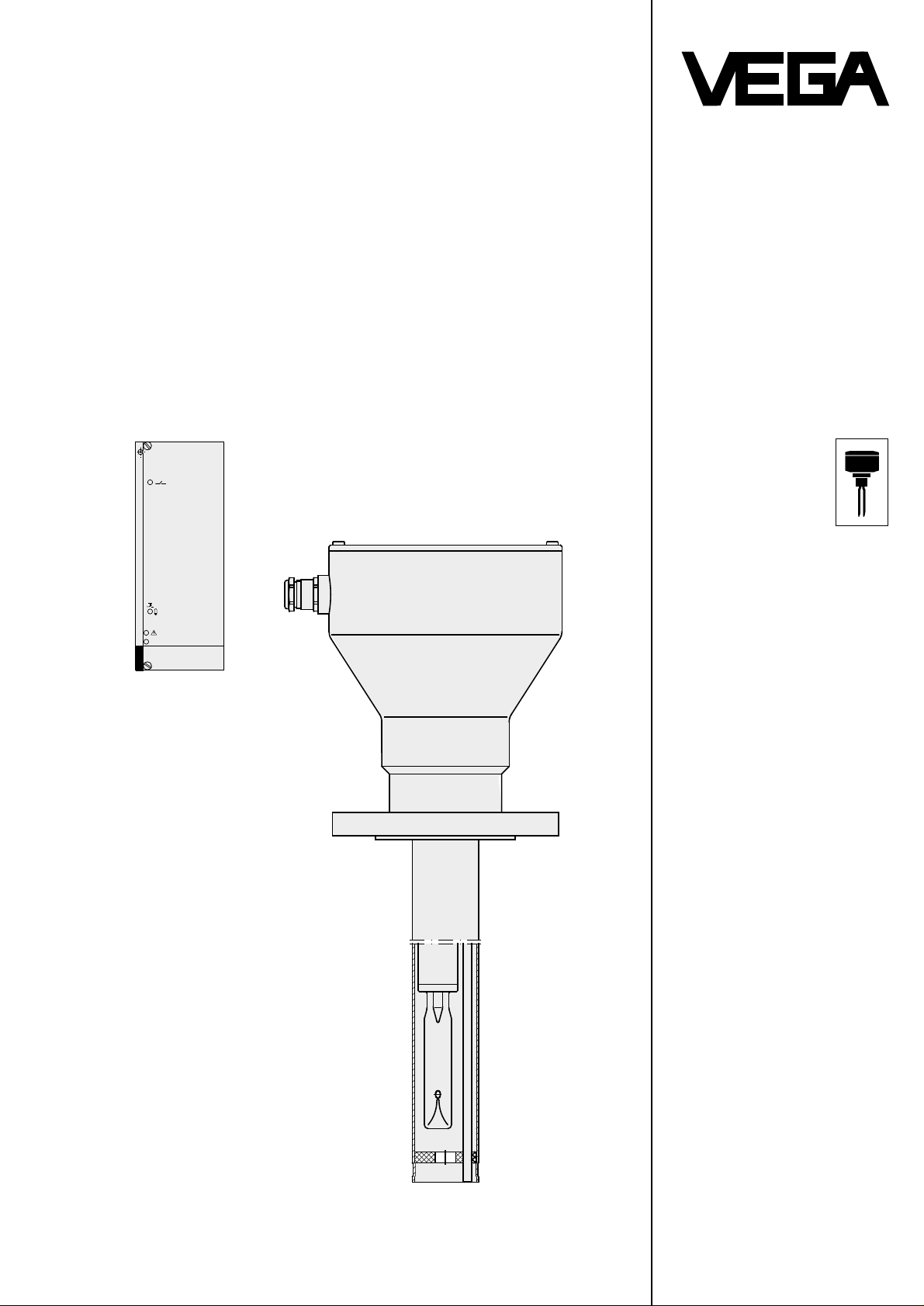
VEGATROL 20 Ex
VEGATOR 526W Ex
on
TIB • Technical Information • Operating Instructions
Fail safe overfill
protection for
pressurized vessels
storing liquid gas
Approved acc. to the
VdTÜV-information
"Overfill protection" 100
no. TÜV.ÜS.94-35
liquid gas PN 25
Corresponds to the
requirements to
component tested overfill
protections of TRB 801,
no. 25
Corresponds to the
requirements of
DIN V 19250 AK 5
Conformity certificates
PTB-no. Ex-94.C.4035 X
BVS-no. 93.C.2015 X
VEGA Grieshaber KG
Electronic level measurement
Am Hohenstein 113
Postfach 11 42
D-77757 Schiltach/Schwarzwald
Phone 0 78 36 / 50 - 0
Fax 0 78 36 / 50 201
Page 2

Contents
1 Introduction
1.1 Contents of the instruction manual ..................................................................................................................... 3
1.2 Safety information ...............................................................................................................................................3
1.3 Approvals ............................................................................................................................................................3
2 Technical Information
2.1 Product description .............................................................................................................................................4
2.2 Configuration of an overfill protection ................................................................................................................. 5
2.3 Configuration of a measuring system .................................................................................................................6
2.3.1 Continuous level measurement ...............................................................................................................6
2.3.2 Additional switch point .............................................................................................................................6
2.4 Technical data ..................................................................................................................................................... 7
2.4.1 Signal conditioning instrument VEGATOR 526 W Ex ..............................................................................7
2.4.2 Sensor VEGASWING Ex with oscillator E86 Ex (overfill protection) .......................................................8
2.4.3 Capacitive measuring electrodes.............................................................................................................9
2.4.4 Housing of the system sensor ................................................................................................................. 9
2.5 Dimensional drawings ....................................................................................................................................... 10
2.5.1 VEGATROL 20 system sensor .............................................................................................................. 10
2.5.2 Flanges .................................................................................................................................................. 11
2.5.3 Signal conditioning instrument VEGATOR 526 W Ex ............................................................................ 11
2.6 Electrical connection ......................................................................................................................................... 12
2.6.1 Signal conditioning instrument VEGATOR 526 W Ex overfill protection ................................................ 12
2.6.2 VEGATROL 20 system sensor .............................................................................................................. 13
2.7 Mounting instructions and regulations .............................................................................................................. 14
2.8 Connection examples for overvoltage arresters ............................................................................................... 15
Contents
3 Mounting and set-up
3.1 Mounting ........................................................................................................................................................... 16
3.2 Set-up................................................................................................................................................................16
3.3 Operation .......................................................................................................................................................... 17
4 Supplement
4.1 Fault signals ...................................................................................................................................................... 17
4.2 Calculation information for sensor length..........................................................................................................18
4.3 General instructions for the use of overfill protections ...................................................................................... 19
2
VEGATROL 20 Ex
Page 3

1 Introduction
1 Introduction
1.1 Contents of the instruction manual
This Technical Information / Operating Instructions
(T.I.B.) contains information for correct
- installation
- connection
- set-up
for the fail-safe-protectionVEGATROL 20 Ex .
This TIB is supplied as part of the order. Knowledge of the
contents is important for correct operation of the
instrument. This TIB accompanies the product and is
addressed to technical staff which are trained or have
knowledge of the use of level measurement and control
equipment.
1.2 Safety information
The instrument must only be operated as described in this
TIB. Please note that other action can cause damage for
which VEGA does not take liability.
1.3 Approvals
VdTÜV
VEGATROL 20 is approved acc. to VdTÜV-information
"Overfill protection" 100 as overfill protection in stationary
storage vessels in liquid gas plants of groups A, B, C and
D (approval no. TÜV.ÜS.94-35).
This approval is also valid for storage vessels in
distribution plants.
DIN
The overfill protection of VEGATROL 20 corresponds to
the requirements of DIN V 19250, class 5.
TRB
VEGATROL 20 corresponds to the requirements on
component tested overfill protections acc. to TRB 801,
no. 25.
Overfill protection in vessels up from group C
Also in cases where TRB 801, no. 25, item 6.1.4.2
requires two independent overfill protections,
VEGATROL 20 is sufficient to meet with this requirement.
one
Ex-Zone 1
The system sensor of VEGATROL 20 is approved for the
use in hazardous areas zone 1. In such cases the
regulations and special conditions of the conformity
certificate PTB-no. Ex-94.C.4035 X and BVS-no.
93.C.2015 X must be observed.
If the capacitive measuring electrode of the system sensor
is used as part of a continuous level measurement or level
detection, the oscillator of the measuring electrode must
be supplied via a suitable intrinsically safe circuit of a
separate signal conditioning instrument.
These are the following possibilities:
- signal conditioning instrument VEGAMET in Ex-version
- signal conditioning instrument VEGAMET or evaluation
system VEGALOG with safety barrier
- signal conditioning instrument VEGATOR in Ex-version
- signal conditioning instrument VEGATOR with safety
barrier.
The regulations and special conditions of the conformity
certificates of the signal conditioning instruments or the
safety barrier must furthermore be observed.
Possible combinations of measuring systems are stated
on page 6.
VEGATROL 20 Ex
3
Page 4

2 Technical Information
2 T echnical Information
2.1 Product description
General
VEGATROL 20 for liquid gas consists of:
- VEGATROL 20 system sensor
- signal conditioning instrument VEGATOR 526 W Ex.
System sensor VEGATROL 20 includes in the concentric
tube the vibrating probe VEGASWING as well as
additionally a capacitive measuring electrode either as rod
or cable electrode.
The oscillators for VEGASWING as well as the measuring
electrode are also integrated in the housing of the system
sensor.
The vibrating level switch in conjunction with VEGATOR
526 W Ex is used as overfill protection.
The capacitive measuring electrode can be used as
follows:
- in conjunction with a signal conditioning instrument
VEGAMET for continuous level measurement
- in conjunction with a signal conditioning instrument
VEGATOR for an additional switch point (e.g.
operational switch-off acc. to VdTÜV).
These signal conditioning instruments are not part of
VEGATROL 20 and have to be ordered separately.
The continuous level measurement as well as the additional level detection are realized via the integral capacitive
measuring electrode. This electrode in conjunction with
the concentric tube or the metallic container wall forms a
capacitor. The liquid gas acts as dielectricum and changes
therefore the capacitance of this capacitor. The respective
oscillator converts the capacitance into a level proportional
direct current. The measuring range includes the total
length of the rod or cable electrode, measured from the
end of the VEGASWING.
The detected level can be used to realize an additional
switch point, e.g. an operational switch off point.
Fail-safe / Self-monitoring
A special feature of the overfill protection of VEGATROL
20 is the integral self-monitoring. It is based on a redundant microprocessor system in the signal conditioning
instrument and includes the whole measuring chain from
the tuning fork via the oscillator, the two-wire line as well
as the signal conditioning instrument.
The self-monitoring includes two routines:
- the permanent monitoring
- the cyclical self-test.
The application range comprises stationary vessels acc. to
the pressure vessel regulations for storing liquid gas acc.
to DIN 51 622:
- in individual vessel plants
- in liquid gas plants
- in distribution plants
- in plants with several vessels
each of group A, B, C and D.
When use in distribution plants up from group C min.
separate overfill protections must be installed acc. to the
requirement of TRB 801, no. 25. Even in these cases
VEGATROL 20 is sufficient due to the VdTÜV-approval to
meet with the TRB-requirement.
In plants with several vessels VEGATROL 20 can be used
as continuous monitoring and locking systems.
two
one
Function
The level is detected by a vibrating level switch
VEGASWING. Its tuning fork is piezoelectrically energized
and vibrates at its mechanical resonance frequency. A
second piezoelectric element measures this resonance
frequency. If the tuning fork is covered by the liquid gas,
the resonance frequency changes proportional to the
degree of covering. The oscillator in VEGASWING detects
continuously the resonance frequency and converts the
value into a current to the signal conditioning instrument.
When the switch point is reached an erratic increase of the
current signal is triggered. The level relay in the signal
conditioning instrument de-energizes.
During the permanent monitoring the signal conditioning
instrument causes the oscillator of the sensor to trigger a
test cycle in 960 msec. cycle. Defined test signals are
transmitted via the two-wire line to the signal conditioning
instrument. Possible failures in the sensor electronics as
well as line break, short-circuit and mechanical damage on
the tuning fork are signalled via these test signals.
During the cyclical selftest security relevant components
and procedures (e.g. level relay, CPU, memory, time
reaction) are checked in the signal conditioning instrument
in a very tough time pattern. The function test of the level
relays is made without interruption of the circuit of
connected systems.
If during the self-monitoring a failure is detected, the level
relays and the fail safe relay de-energize.
Due to the above mentioned measures a reliable and
correct function of the overfill protection is ensured without
any staff involved for control tasks.
4
VEGATROL 20 Ex
Page 5
2 Technical Information
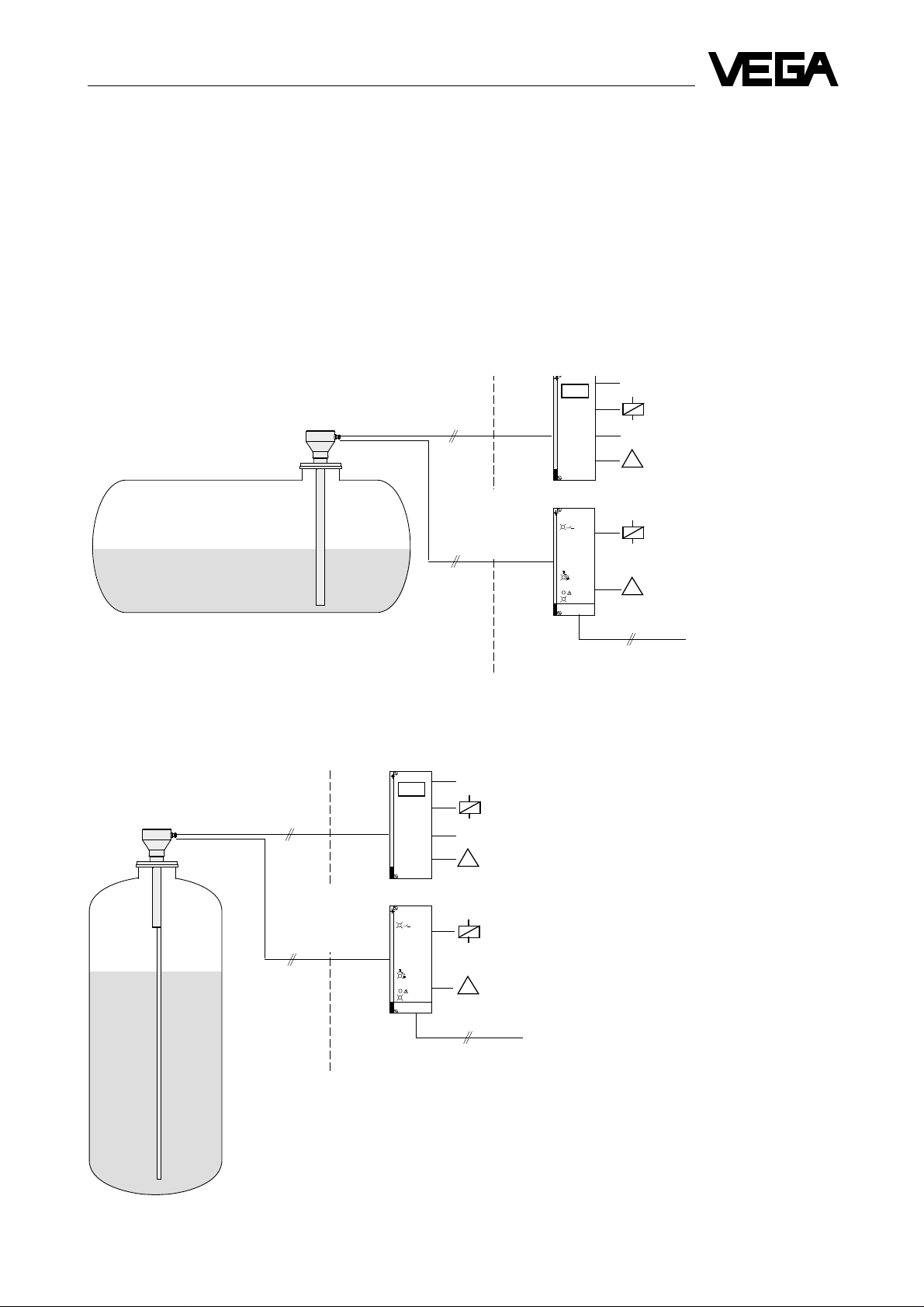
2.2 Configuration of an overfill protection
Storage vessels in liquid gas plants of group A, B, C and D
The overfill protection VEGATROL 20 for a storage vessel consists of:
- VEGATROL 20 system sensor with rod and cable electrode
- signal conditioning instrument VEGATOR 526 W Ex.
Additional instruments:
- signal conditioning instrument VEGAMET for continuous level measurement or for additional switch point
- overvoltage arresters etc. acc. to the requirements of the system.
Version I: cylindrical tank
Ex-Zone 1
e.g. rod electrode
Version II: spherical tank
VEGATROL 20
System sensor
Ex-Zone 1
e.g. cable
z.B. Seil-
electrode
elektrode
VEGATROL 20
System sensor
two-wire
line each
(intrinsically safe
circuit)
two-wire
line each
(intrinsically safe
VEGAMET Ex
0/4 … 20 mA
VEGATOR 526 W Ex
•
•
•
•
•
VEGATOR 526 W Ex
VEGATOR 526 W Ex
on
DISBUS
!
!
circuit)
Not-Ex-area
VEGAMET Ex
0/4 … 20 mA
VEGATOR 526 W Ex
•
•
•
•
•
VEGATOR 526 W Ex
VEGATOR 526 W Ex
on
Continuous level
measurement
Overfill
protection
DISBUS
!
!
Continuous level
measurement
Overfill
protection
VEGATROL 20 Ex
Not-Ex-area
5
Page 6
2 T echnical Information
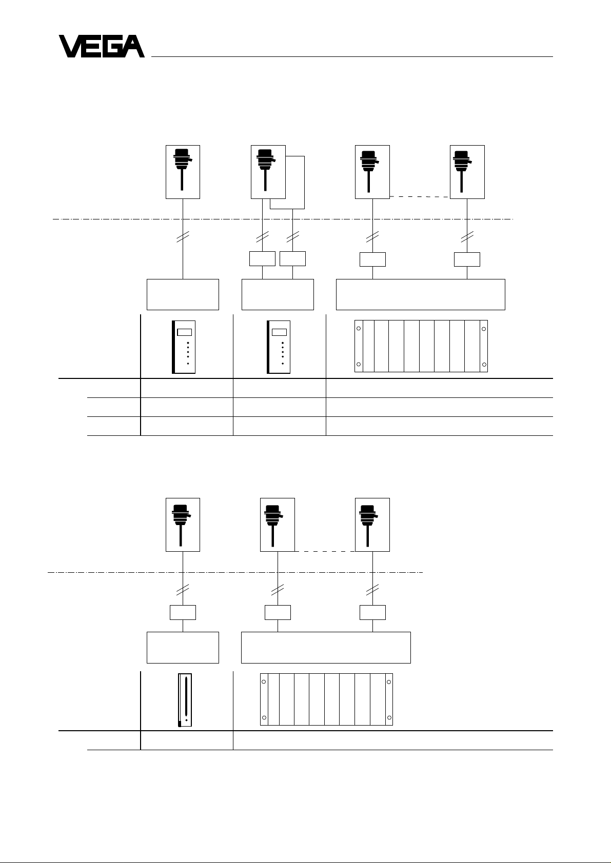
2.3 Configuration of a measuring system
2.3.1 Continuous level measurement
Sensor VEGATROL 20 VEGATROL 20 VEGATROL 20
1
2
Ex-area
Not Ex-area
Safety barrier 145 145 145 145
Signal conditioning VEGAMET VEGAMET VEGALOG 571
instrument 509 Z Ex 512 Z EA-card (input analog)
1
10
Outputs
Relay 3 x 3 x 10 x per AR-card (output relay)
Current 1 x 3 x 10 x per AA-card (output analog)
DISBUS 1 x 1 x for max. 30 VEGADIS per AD-card (output DISBUS)
2.3.2 Additional switch point
Sensor VEGATROL 20 VEGATROL 20
1
Ex-area
Not Ex-area
Safety barrier 145 145 145
Signal conditioning VEGATOR VEGALOG 571
instrument 525 F EA-card (input analog)
10
Outputs
Relay 1 x 10 x per AR-card (output relay)
Additional instruments for measuring systems - Overvoltage arresters
- Indicators VEGADIS 171 A / 172 (0 … 20 mA)
- VEGADIS 173 (DISBUS)
- Interface converters VEGACOM 557
6
VEGATROL 20 Ex
Page 7

2 Technical Information
2.4 Technical data
2.4.1 Signal conditioning instrument VEGATOR 526 W Ex
Power supply
Operating voltage U
Power consumption approx. 11 VA or approx. 8 W
Fuse (intern) Plug fuse 800 mA, moderately slow blow
Measuring data input - Operating data
Data transmission analog, 4 … 20 mA
Power supply 14 … 18,9 V DC
Current limitation at 45 mA, short-circuit proof
Connection line 2-wire
Resistance per conductor max. 35 Ohm
Measuring data input - Ex-technical data
Max. values: Voltage U ≤ 18,9 V DC
Current I ≤ 95 mA
Efficiency P ≤ 647 mW
Characteristics trapezoidal
Internal effective inductance L
Internal effective capacitance C
int
int
= 24 V AC (20 … 28 V), 50 / 60 Hz or
nenn
= 24 V DC (16 … 60 V)
unimportant
≤ 10 nF
Flame proofing EEx … IIC EEx … IIB
Max. permissible outer inductance L
ext
… ia… 0,5 mH 1 mH 1,5 mH 2 mH 0,5 mH 1 mH 1,5 mH 2 mH
… ib… 4 mH 15 mH
Max. permissible external capacitance C
… ia… 52 nF 40 nF 27 nF 15 nF 200 nF 190 nF 177 nF 160 nF
ext
… ib… 240 nF 1,1 F
The intrinsically safe circuit is reliably galvanically separated from the not-intrinsically safe circuits up to a peak value of
375 V of the nominal voltage.
Level relay
Contact 1 floating spdt, AgCdO and gold flashed
Min. turn-on voltrage 12 V DC
switching current 10 mA DC
Max. turn-on voltage 250 V AC, 48 V DC
switching current 2,5 A at 250 V AC; 1 A at 48 V DC
breaking capacity 125 VA AC
Required external fuse
for relay contacts 2 A, slow
Fail safe relay
Contact 1 floating spdt, AgCdO and Au platted
Min. turn-on voltage 10 mV
switching current 10 µA
Max. turn-on voltage 250 V AC, 60 V DC
switching current 2 A AC, 1 A DC
breaking capacity 125 VA AC, 60 W DC
Ambient conditions
Permissible operating temperature -20°C … +70°C
Storage and transport temperature -25°C … +80°C
Electrical connection
Connection Plug connection acc. to DIN 41 612, series F, 32-pole, d, z
Carrier 596 Ex Connection to the respective module
Housing 589 - 10 Ex Connection to terminal (max. 1,5 mm
VEGATROL 20 Ex
2
)
7
Page 8

2 T echnical Information
Electrical protective measures
Protection unassembled IP 00
installed in Carrier Type 596 Ex with Ex-module
front completely equipped .........................IP30
Upper and lower side ................................IP20
Wiring side rear .........................................IP00
installed in Housing Type 589 - 10 Ex ......................... IP30
(in both cases observe the respective TIB)
Protection class II (in housing 589)
Overvoltage category II
Mechanical data
Series Module unit for carrier type 596 Ex or
housing 589 - 10 Ex
Dimensions unassembled W = 50,8 mm (10 TE), H = 128,4 mm, D = 162 mm
Dimensions in plastic housing 589 W = 62,5 mm, H = 136 mm, D = 222 mm
Weight approx. 400 g
VEGATOR 526 W Ex must only be connected to instruments in which no higher voltages than AC 250 V (50 Hz) occur.
Potential stages and galvanic separation
Sensor
Ex-area
Meas. data input Power sup. unit
P1
Microcomputer control and output Relay contacts Relay contacts
P3 P4 P5
Fail safe relay Level relay
Voltage supply
P2
2.4.2 Sensor VEGASWING Ex with oscillator E86 Ex (overfill protection)
Supply and signal circuit
Power supply 12 … 18,9 V DC
(from signal conditioning instrument VEGATOR 526 W Ex)
Data transmission analog, 4 … 20 mA
Flame proofing EEx ia IIC, T4
Internal effective capacitance C
Internal effective inductance L
Power consumption Tuning fork uncovered ca. 7 mA
Tuning fork covered 10 … 20 mA
Fault signal approx. 25 mA
Reference value approx. 15 mA
Connection line 2-wire
unimportant
int
unimportant
int
P1 … P5
Potential stages
Ambient conditions
Permissible operating temperature -30°C … +70°C
Storage and transport temperature -40°C … +80°C
Operating pressure max. 25 bar
however observe max. permissible pressure of the flange
Electrical connections
Terminals in plastic housing for connection of max. 1,5 mm
Cable entry Pg 13,5
Electrical protective measures
Protection class II
8
2
VEGATROL 20 Ex
Page 9

2 Technical Information
Mechanical data
Material Mounting parts Stainless steel1.4571 (V4A)
Extension tube Stainless steel 1.4571 (V4A)
Tuning fork Stainless steel 1.4581 (V4A)
Resonance frequency of the tuning fork in air approx. 380 Hz
Dimensions see dimensional drawing
2.4.3 Capacitive measuring electrodes
Supply and signal circuit
Oscillator 117/4 A Ex, continuous level measurement
Power supply approx. 17,8 V at 4 mA, approx. 14 V at 25 mA
(data of VEGAMET 509 Z Ex)
ca. 12 … 16 V (via ia-safety barrier 145)
Data transmission analog, 4 … 20 mA
Flame proofing EEx ia IIC, T6
Internal effective capacitance C
Internal effective inductance L
Oscillator 115 A Ex, additional switch point (only with rod electrode)
Power supply ca. 12 … 16 V (via ia-safety barrier 145)
Data transmission analog, 4 … 20 mA
Flame proofing EEx ia IIC, T6
Internal effective capacitance C
Internal effective inductance L
Ambient conditions
Permissible operating temperature -30°C … +70°C
Storage and transport temperature -40°C … +80°C
Operating pressure max. 25 bar
unimportant
int
unimportant
int
unimportant
int
≤ 0,2 mH
int
Electrical connection
Terminals for max. 2,5 mm
2
Cable entry Pg 13,5
Electrical protective measures
Protection class III
Mechanical data
Material Mounting parts Stainless steel 1.4571 (V4A)
Isolation PTFE partly insulated
Electrode rod Stainless steel 1.4571 (V4A)
Electrode cable Stainless steel 1.4571 (V4A)
Fixing insulator Porcelain
max. tensile strength cable electrode 3 KN
Dimensions see dimensional frawing
(max. rod length 4000 mm, max. cable length 12000 mm)
2.4.4 Housing of the system sensor
Mechanical data
Material Housing Stainless steel 1.4571 (V4A)
Flange Stainless steel 1.4571 (V4A)
Concentric tube Stainless steel 1.4571 (V4A)
Pg-cable entry brass nickle plated
Fixing pieces in the concentric tube PTFE
Dimensions see dimensional drawing (concentric tube length 4000 mm)
Weight basic weight approx. 4 kg
per metre concentric tube additional approx. 1 kg
Electrical protective measures
Protection IP 67
VEGATROL 20 Ex
9
Page 10

2.5 Dimensional drawings
2.5.1 VEGATROL 20 system sensor
(approx. dimensions in mm)
with rod electrode with cable electrode
32
ø170
32
2 T echnical Information
ø170
Pg 13,5
195
b
L1
L2
25
100
Switch point
Rod electrode
195
b
L1
Pg 13,5
L2
25
ø48,3
ø2,5
Switch point
100
40
Cable electrode
ø48,3
L1: length of the concentric tube and
the rod electrode
L2: length of the tuning fork sensor
(concentric tube and rod electrode
have the same length)
An additional switch point can be realized with the
capacitive measuring electrode. In this case the rod
electrode must be selected min. 300 mm longer than the
distance of the lower flange edge to the requested switch
point.
L3
L1: length of the cable electrode
L2: length of the tuning fork sensor
L3: length of the fixing facility
(min. 200 mm, max. 250 mm)
Note:
- the cable electrode inside the concentric tube is
designed as rod electrode
- the dimension "L2" is mentioned on the type plate as
length of the overfill protection
- flange thickness "b" see next page
10
VEGATROL 20 Ex
Page 11

2 Technical Information
2.5.2 Flanges
The welded flanges for system sensor VEGATROL 20 are made of stainless steel (material no. 1.4571, V4A) acc. to
DIN 2527 or ANSI - ASA - B 16,5.
Flange acc. to DIN (Dimensions in mm)
90°
45°
Flange Dimensions Holes
DN PN D b k Number Screws d
50 25 / 40 165 20 125 4 M16 18
65 25 / 40 185 22 145 8 M16 18
80 25 / 40 200 24 160 8 M16 18
100 25 / 40 235 24 190 8 M20 22
150 25 / 40 300 28 250 8 M24 26
d
2
b
ø k
ø D
D = outer flange diameter
b = flange thickness
k = hole circle
d
= diameter of holes
2
Flange acc. to ANSI (Dimensions in mm)
Flange Dimensions Holes
ANSI psi D b k Number Screws d
2" 600 165,1 25,4 127,0 8 M16 19,1
1
2
/2" 600 190,5 28,4 149,4 8 M20 22,4
3" 600 209,6 31,8 168,1 8 M20 22,4
4" 600 273,1 38,1 215,9 8 M24 25,4
2.5.3 Signal conditioning instrument VEGATOR 526 W Ex
(approx. dimensions in mm)
2
2
12
Circuit board 100 x 160 x 1,5 Multipoint connector
European size
100
162
4
10 TE
128,4
50,8
VEGATROL 20 Ex
11
Page 12

2.6 Electrical connection
2.6.1 Signal conditioning instrument VEGATOR 526 W Ex overfill protection
Coordination of the Terminal socket with multipoint Module with multipoint
terminal socket or the connector (part of the housing connector acc. to DIN
multipoint connector Type 589 - 10 Ex) 41 612 for carrier
d b z
2 L1 (+)
18
20
30
32
N (-)
2
4
8
8
10
Power
supply
Fail safe relay
Level relay
(overfill
protection)
+
Measuring
-
data input
(intrinsically
safe signal
circuit)
10
12
14
16
18
20
22
24
28
30
32
d
2
4
6
8
z
2
4
6
8
10
12
14
16
18
Coded
key
20
22
24
E Ex i
28
30
32
d
z
2 T echnical Information
(rear view)
d b z
2
4
6
8
10
12
14
16
18
Separation
20
22
24
26
28
30
32
Not Ex-area
Ex-area
Note:
- the relay contacts are shown in currentless condition
Sensor 1
2 3
1
Ex-separation
Overvoltage arrester
Connection when using
overvoltage arresters, see
page 15
Overvoltage arrester
Oscillator E86 Ex of
VEGASWING in the housing
of the system sensor
12
VEGATROL 20 Ex
Page 13

2 Technical Information
2.6.2 VEGATROL 20 system sensor
Inner view after removing the cover
Oscillator E86 Ex of the
overfill protection
123
Earth connection
Pg 13,5
Plastic cover (visible after
removing the oscillator)
Overfill protection
Connection
1
2
3
Continuous level measurement
Blind stopper or Pg 13,5
(attached to consignment)
Oscillator 117/4 A Ex or 115 A Ex
of the capacitive measuring
electrode
d32
-
+
d30
Signal conditioning
instrument
VEGATOR 526 W Ex
Terminals
(visible after removing the plastic cover)
2
1
VEGATROL 20 Ex
3
4
Connection
2
3
1
4
d32
-
+
d30
Signal conditioning
instrument, e.g.
VEGAMET 509 Z Ex
13
Page 14

2 T echnical Information
2.7 Mounting instructions and
regulations
General instruction for electrical connection
The electrical connection is made acc. to the wiring diagram on page 12 and 13 or acc. to the type plates on the
instruments. The voltage stated on the type plate of the
signal conditioning instrument must correspond with the
value of the power supply.
Coding
A mechanical coding in form of a pin in the multipoint
connector and a hole in the multiple plug ensures that only
one Ex-instrument can be plated in one Ex-module (carrier
or housing).
In case of connection of a sensor installed in the Ex-area it
must be ensured that VEGATOR 526 W Ex (see figure) is
provided with a coded key in the respective position.
Ex-modules of Messrs. VEGA are supplied with plugged in
coded key.
2
4
6
8
10
12
14
16
18
20
Coded key here
Coding on the multipoint connector
(view)
22
24
26
28
30
32
- If strong electromagnetic interferences have to be
expected, screened cable is recommended.
- If there is a danger of overvoltages, overvoltage
arresters are recommended. Observe the respective
TIB for connection.
- Connected systems must correspond to VDE 0100
part 725 (auxiliary circuits).
- If screened cable is used, the screening should be
earthed at one end. The earth must be realized on the
sensor.
- The respectively valid Ex-regulations as well as the
special conditions in the conformity certificate must be
observed.
Ex-mounting regulations
The signal conditioning instrument VEGATOR 526 W Ex
and the signal conditioning instrument for the capacitive
measuring electrode must be installed generally outside
hazardous areas (or special Ex-protective measures must
be taken).
Installation into carrier (DIN 41 494 part 5)
VEGATOR 526 W Ex must be installed such that a
protection of min. IP 20 (acc. to IEC 144 (529)) is reached.
This is ensured with carrier type 596 Ex. It must be
furthermore observed that a min. distance of 50 mm is
kept between intrinsically and not-intrinsically safe circuits.
This can be realized by adding a separation (included in
"VEGA-module"). The requred air gaps and creeping
distances between the instruments in the carrier must be
maintained. Observe therefore EN 50 020, especially
schedule 2, modification 2. The following instructions are
valid with e.g. a voltage of 250 V AC, 50 Hz (corresponds
to a peak value of 375 V) in neighbouring instruments:
- Between the left carrier wall and VEGATOR 526 W Ex
a distance of 2 TE must be maintained.
- If a power supply unit VEGASTAB 592 or 593 is used,
observe the mounting instructions in the TIB of the
carrier.
- If VEGATOR 526 W Ex is mounted together with notEx-instruments or instruments of other manufacturers in
a carrier, a min. distance of 2 TE must be maintained to
these instruments.
- This min. distance is not required if the VEGAinstrument (10 TE width) on the left of VEGATOR 526
W Ex is provided with a black cover on its right side.
Installation into housing type 589 - 10 Ex
In case of installation of VEGATOR 526 W Ex into housing
type 589 - 10 Ex the distances between intrinsically and
not intrinsically safe circuits must be maintained.
General mounting and installation regulations
- The wiring between signal conditioning instrument and
sensor can be made with standard cable suitable and
marked for intrinsically safe circuits.
- Line resistance, max. permissible outer inductance and
capacitance, see technical data, page 7 and 9.
14
VEGATROL 20 Ex
Page 15

2 Technical Information
2.8 Connection examples for overvoltage arresters
Vessel without cathodic tank protection
Ex-area Not Ex-area
VEGATROL 20
System sensor
117/4 A Ex
or
115 A Ex
E86 Ex
External earth terminal
Overvoltage arrester
Type B 62 - 27 Ex 0-2
or B 62 - 27 Ex-2
Overvoltage arrester
Outer isolation
1
2
1
2
Line length
≤ 50 m
A1
B62-27
A2
A1
B62-27
A2
Screen
min. 4 mm2 Cu
Metal housing isolated or
plastic housing
E1
Typ
E2
E1
Typ
E2
Earth- / PAconnection terminal
Outer isolation
Screen
either
overvoltage arrester
E1
Typ
B62-27G
E2
Typ
E1
B62-27G
E2
intrinsically safe
A1
A2
A1
A2
circuit to signal
conditioning
instrument
VEGATOR
526 W Ex
d30
d32
Note:
- Suitable cable must be used, either with metal cover (or screen). If a
(control room)
to potential
equalization line
cable with metal cover or screen is used (as on above figure), a potential
equalization along the entire length of the intrinsically safe circuit is not
necessary. Screen or metal cover must only be connected to the
overvoltage arrester.
- The current load capacity of the screen must correspond at least to that
of a 1,5 mm
2
Cu-line.
Vessel with cathodic tank protection
Ex-area Not Ex-area
Overvoltage arrester
Type B 62 - 27 Ex 0 - 2
or B 62 - 27 Ex - 2
VEGATROL 20
System sensor
117/4 A Ex
or
115 A Ex
E86 Ex
External earth
terminal
1
2
1
2
Cathodic tank protection
2 … 24 V
(object voltage)
Outer isolation
Line length
≤ 50 m
Screen
min. 4 mm
(control room)
either
overvoltage arrester
E1
Typ
B62-27G
E2
Typ
E1
B62-27G
E2
intrinsically safe
A1
A2
A1
A2
circuit to signal
conditioning
instrument
d30
d32
Overvoltage arrester
A1
Typ
B62-27
A2
A1
Typ
B62-27
A2
2
Cu
Metal housing isolated or
plastic housing
E1
E2
E1
E2
Outer isolation
Screen
Earth- / PA
connection terminal
Note:
- Suitable cable must be used with metal cover (or screen). Screen or
metal cover must only be connected to the overvoltage arrester.
Screen or metal cover must not be earthed.
- The cable must have an outer isolation.
- The current load capacity of the screen must correspond at least to that
of a 1,5 mm
2
Cu-line.
VEGATOR
526 W Ex
VEGATROL 20 Ex
15
Page 16

3 Mounting and set-up
3 Mounting and set-up
3.1 Mounting
The tuning fork of system sensor VEGATROL 20 is within
the concentric tube. The length from the flange lower edge
to the end of the tuning fork is stated on the type plate
(corresponds to the dimension L2, page 10).
The switch point must be generally at 85 % of the vessel
volume.
The adaption to the respective vessel dimensions is
realized via dimensioning of the concentric tube.
Calculation help see supplement.
A sealing must be used between flange and system
sensor which is suitable for the use in liquid gas plants.
In case of installation lengths of the system sensor
exceeding 1,5 m the extension tube in the vessel must be
protected against bending (e.g. vibrations by fluctuating
product). If there is danger of mechanical damage, the
extension tube in the vessel must be protected against
bending.
The system sensor with cable electrode is supplied with
fixing insulator and fixing spring. The cable electrode must
be fixed via the fixing spring and the fixing insulator to the
bottom of the vessel (the spring is used to tighten the
cable electrode).
Pre-requirements for set-up
- the sensor VEGATROL is installed in its final position
and the tuning fork is not covered
- the failure LED is dark
The set-up is carried out by pushing the set-up key for
approx. 4 sec.
During set-up, VEGATOR is adapted to VEGASWING.
The actual resonance frequency is detected as current by
VEGATOR and stored as reference value.
Condition up to approx. 4 secs. after set-up:
Yellow LED lights
VEGATOR 526 W Ex
Green LED in set-up key lights
on
Green LED lights
Condition up from approx. 4 secs. after set-up:
The system sensor must be generally mounted vertically.
3.2 Set-up
After electrical connection of VEGASWING Ex to
VEGATOR 526 W Ex the overfill protection goes to
operating status.
Operating status before set-up:
Yellow LED lights
VEGATOR 526 W Ex
on
(= level relay de-energized)
Green LED in set-up key flashes
(= set-up not yet carried out)
Green LED lights
(= supply voltage in)
VEGATOR 526 W Ex
on
Green LED lights
Note:
- If the signal conditioning instrument VEGATOR
526 W Ex is exchanged by a new instrument of the
same type, the set-up must be repeated.
- The set-up of the continuous level measurement or
level detection is made acc. to the description in the TIB
of the signal conditioning instrument used.
16
VEGATROL 20 Ex
Page 17

4 Supplement
3.3 Operation
If in case of overfilling, the tuning fork is covered up to the
switch point with the liquid gas, the level relay de-energizes with a delay of approx. 500 msec. and the respective
LED lights.
This remains as long as the fork is covered.
If the level reduces below the switch point, the relay
energizes with a delay of approx. 1 sec. and the
respective LED extinguishes.
4 Supplement
4.1 Fault signals
There are two error classes concerning the condition of
the LED in the front panel:
- error during set-up
- error detected during the self-monitoring.
Level and fail safe relays de-energize in both cases.
In case of failures during set-up, start again (switch off the
voltage and switch on again) and repeat the set-up acc. to
section 3.2.
If an error is detected, the voltage must be switched off
first, the failure (e.g. line break) removed and then the
voltage switched on again. It is not necessary to repeat
the set-up.
Failure reason Failure treatment
External failure Remove the fault and
(line break, short-circuit, start again
fault SWING-electronic)
Set-up was carried out Start again and repeat
when tuning fork was set-up with uncovered
covered tuning fork
Set-up key was pushed Start again and repeat
too long (> 6 secs.) set-up correctly
Error during self-monitoring
lights
VEGATOR 526 W Ex
on
Failure reason Failure treatment
Line break, Remove failure and start
short-circuit again
Component failure Inform VEGA-service or
lights
return the instrument for
invertigation
Error during set-up
VEGATOR 526 W Ex
on
lights
lights for approx. 2 sec.
lights
VEGATROL 20 Ex
17
Page 18

4.2 Calculation information for sensor length
The determination of the sensor length must be generally made with the respective expert.
Example: cylindrical tank
3000 mm
L
Volume 85 %
corresponds to 2400 mm
0 mm
4 Supplement
600 mm distance from
flange lower edge to the
determined swicht point
Procedure
- calculate the level of the max. permissible volume
85 %, e.g. 2400 mm
- determine the distance from the flange lower edge up
to the calculated level
- determine the total length of VEGASWING
L = distance + 25 mm
(25 mm = submerging depth up to the switch point)
in this example
L = 600 m + 25 mm = 625 mm
A VEGASWING with a total length of 625 mm must be
ordered.
Note:
An increase of the total length of VEGASWING will cause
the instrument to respond even at low levels, a reduction
causes a response at higher levels.
If the required total length cannot be exactly determined,
the calculated value must be rounded up (determination to
the safe side).
18
VEGATROL 20 Ex
Page 19

4 Supplement
4.3 General instructions for the use of
overfill protections
Application of a liquid gas overfill protection (ÜFS) is to
monitor the level of the liquid gas stage and to interrupt
the filling procedure when the permitted level in the vessel
is reached and to trigger an acoustic or optic alarm.
The configuration as well as the operation of such an
overfill protection must always meet with the requirements
of an overfill protection as well as the special conditions of
the VdTÜV-regulation "overfill protection 100".
This furthermore requires that the filling of a pressurized
vessel for liquid gas is only possible if it is ensured that the
overfill protection works interferencefree and correctly. At
least before each filling procedure the whole measuring
system of the overfill protection must be checked.
Normally this test of overfill protections is triggered by a
manually triggered test key. In case of failure the filling
must be suppressed by a locking circuit.
Due to the self-monitoring, this test is not necessary with
VEGATROL.
The overfill protection always operates discontinuously
and can be planned and operated independent from the
function of the continuous level measurement. The
continuous level measurement is not subjected to the
special requirements to the functional reliability of the
overfill protection.
However both have to be included in an alarm system as
follows:
- the continuous measurement generates the pre-alarm
signal and controls an acoustic or optic warning system
or interrupts the filling procedure
- the overfill protection triggers a main alarm signal and
stops the system
Criteria for dimensioning:
- triggering pre-alarm, e.g. at 83 % to filling (dependent
on the vessel geometry)
- triggering main alarm, generally at 85 % filling
- tolerance of the switch point of the overfill protection:
± 1 %
The pre-alarm is adjusted such that there is sufficient time
to avoid response of the overfill protection.
VEGATROL 20 Ex
19
Page 20

VEGA Grieshaber KG
Electronic level measurement
Am Hohenstein 113
Postfach 11 42
D-77757 Schiltach/Schwarzwald
Phone 0 78 36 / 50 - 0
Fax 0 78 36 / 50 201
Technical data subject to alterations 2.17 749 / Sept. '94
 Loading...