

Page 1

Operating Instruction
VEGATRENN 548 V Ex
Level and Pressure
on
VEGATRENN
548 V Ex
out
in
Page 2

Inhaltsverzeichnis
Sicherheitshinweise...................................................................... 2
1 Produktbeschreibung
1.1 Funktion, Aufbau und Einbau............................................... 3
1.2 Technische Daten ................................................................. 5
1.3 Abmessungen ....................................................................... 7
1.4 Zulassungen ......................................................................... 7
1.5 Typschild ............................................................................... 7
2 Montage ....................................................................................... 8
3 Elektrischer Anschluß
3.1 Errichtungshinweise ............................................................. 9
3.2 Anschlußhinweise ............................................................... 10
3.3 Anschlußplan ...................................................................... 10
3.4 Anschlußbeispiele ............................................................... 11
4 Inbetriebnahme......................................................................... 14
Contents
5 Diagnose
5.1 Wartung ............................................................................... 14
5.2 Reparatur ............................................................................ 14
5.3 Störmeldung ........................................................................ 14
Safety information
The described module must only be installed
and operated as described in this operating
instruction. Please note that other action can
cause damage for which VEGA does not take
responsibility.
2 VEGATRENN 548 V Ex
Page 3
Product description
1 Product description
1.1 Function, configuration and
mounting
Function
Ex-separator VEGATRENN 548 V Ex is used
for intrinsically safe, galvanically isolated
supply of up to 15 digital (VBUS) presure
transmitters. At the input side it is connected
to the tow-wire-VBUS-line of the signal
conditioning instruent and provides at the
output side 15 intrinsically safe ia-circuits.
The Ex-separator can be used in conjunction
with the following signal conditioning
instruments or sensors:
- VEGAMET 514 V and 515 V
- EV-card of VEGALOG 571
- pressure transmitter D80, D81, D84 or D86
in Ex-version with VBUS-electronics E23V
The ia-circuits are divided into 3 branches, up
to five sensors can be connected to each
branch. The ia-circuits are galvanically
connected and a fuse per branch is used for
safety reasons.
The intrinsically safe circuits are galvanically
isolated from the not intrinsically safe circuits.
Power supply
Intrinsically safe iacircuits
Signal
conditioning
instrument
(VBUS)
Electronics
Branch 1
Branch 2
Branch 3
Configuration
The Ex-separator VEGATRENN 548 V Ex is
designed in 19“-technology with 5 TE (=
25,4 mm). The connection is made via a multiple plug acc. to DIN 41 612.
Mounting
There are the following mounting possibilities:
- in housing type 506 with VEGAMET
- in carrier BGT 596 Ex with VEGAMET
- in carrier BGT LOG 571 *
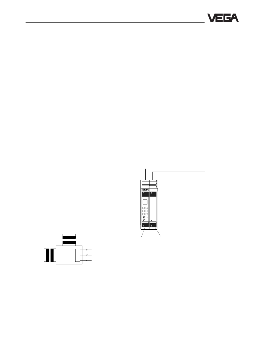
Example 1:
In housing type 506 with VEGAMET
Not-Ex-area
Supply
VEGAMET
VEGATRENN
515V
548VEx
VEGAMET
514 V
515 V
VEGATRENN
548 V Ex
)
with VEGALOG
Ex-area
VBUS ia IICcircuits
Fig. 1.1: Block diagram of the Ex-separator
*) If several VEGATRENN 548 V Ex are used, it is
recommended to separate them into the cheaper
BGT 596 Ex.
VEGATRENN 548 V Ex 3
Page 4
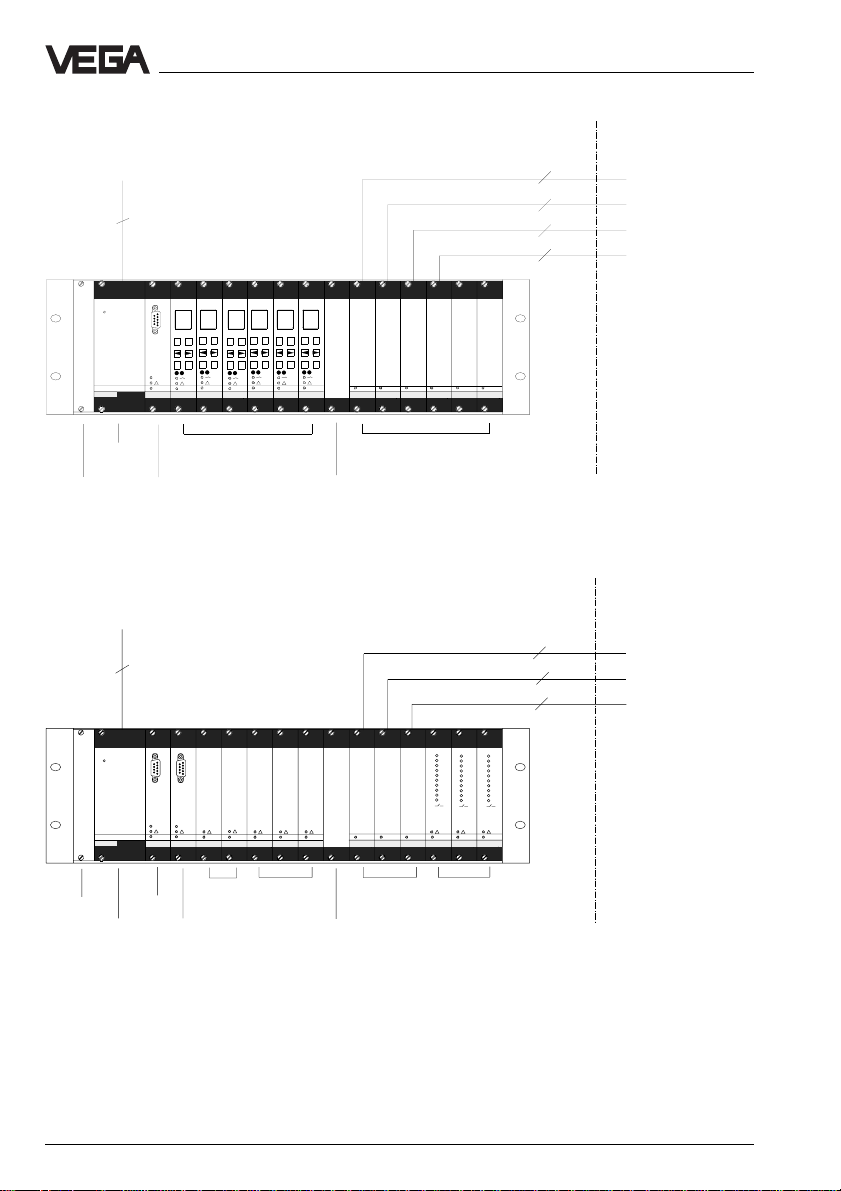
Example 2: In BGT 596 Ex M with VEGAMET
Supply
2
PC
–
–
–
+
–
+
OK
ESC
OK
ESC
BA
VEGAMET
VEGACOM
VEGASTAB
593
VEGAMET
515V
557
515V
–
+
+
–
ESC
VEGAMET
+
+
OK
ESC
OK
VEGAMET
515V
OK
ESC
OK
ESC
VEGAMET
VEGAMET
515V
515V
515V
548 V Ex
Product description
Not-Ex-area
2 x 2
2 x 2
2 x 2
2 x 2
VEGATRENNVEGATRENN
VEGATRENNVEGATRENN
VEGATRENN
548VEx
548 V Ex
VEGATRENN
548VEx
548 V Ex
548 V Ex
Ex-area
VBUS ia IICcircuits
Power
supply unit
Blind cover
VEGACOM
557
VEGAMET 515 V VEGATRENN
Blind cover
Example 3: In BGT LOG 571 with VEGALOG
Supply
2
PC
PC
BA
BA
VEGACOM
VEGACOM
VEGALOG
VEGASTAB
Blind cover
Power
supply
unit
593
557
CPU
VEGACOM
557
VEGALOG
557
571EA
EAcards
VEGALOG
VEGALOG
VEGALOG
571 EA
571 EV
571EV
EVcards
571EV
VEGATRENN
548 V Ex
VEGATRENN
548 V Ex
Blind cover
548 V Ex
VEGATRENN
548VEx
VEGATRENN
VEGALOG
548 V Ex
Not-Ex-area
1
1
2
2
3
3
4
4
5
5
6
6
7
7
8
8
9
9
10
10
VEGALOG
VEGALOG
571 EA
571EA
Output
cards
Ex-area
15 x 2
15 x 2
15 x 2
1
2
3
4
5
6
7
8
9
10
571 EA
VBUS ia IICcircuits
4 VEGATRENN 548 V Ex
Page 5
Product description
1.2 T echnical data
Power supply
Operating voltage U
Power consumption approx. 4 W, approx. 6 VA
Fuse 1 A, slow-blow
Signal conditioning instrument circuit
For connection to signal conditioning instrument VEGAMET 514 V,
Input voltage U
The signal conditioning instrument circuit must only be connected to instruments with an
operating votlage less than 250 V.
Sensor circuit
Number 3 branches with 5 sensor current circuits each
Sensors hydrostatic pressure transmitter with
Voltage at 5 mA approx. 15 V DC, at 25 mA approx.
Current limitation at approx. 30 mA, shortcircuit proof
Fuse per circuit 1 fuse 40 mA, slow-blow
Connection line 2-wire (standard line) *
Resistance per conductor max. 15 Ω
Line length max. 1000 m
= 24 V AC (20 … 53 V), 50/60 Hz
nenn
= 24 V DC (20 … 72 V)
515 V or EV-card of VEGALOG 571
= 25 V DC with VEGAMET
nenn
= 24 V DC with EV-card VEGALOG
electronics type B (VBUS)
13,5 V DC
)
Sensor circuits, Ex-technical data
Classification [EEx ia] IIC, [EEx ia] IIB, [EEx ib] IIC, [EEx ib] IIB
Max. values (per branch)
- voltage U
- current I
- efficiency P
Characteristics linear
- 18,2 V
O
- 270 mA
O
- 926 mW
O
EEx ia IIC EEx ia IIB EEx ib IIC EEx ib IIB
Max. permissible outer inductance L
0,41 mH 1,8 mH 0,41 mH 1,8 mH
a
Max. permissible outer capacitance Ca83 nF 384 nF 290 nF 1300 nF
The intrinsically safe sensor current circuits are reliably galvanically isolated from the not
intrinsically safe circuits up to a peak value of the nominal voltage of 375 V.
Indicating elements
LED in front plate green on: operating voltage on
*)screened cable is recommended for electromagnetic interferences.
VEGATRENN 548 V Ex 5
Page 6

Product description
Electrical connection
Multiple plug component acc. to DIN 41 612, series F, 33-pole,
3 rows d, b, z (partly equipped)
In conjunction with
- carrier
BGT 596 Ex, BGT LOG 571 connection to appropriate Ex-module
- housing type 506 connection to screw terminals (max. 2,5 mm
Protective measures
Protection
- not mounted IP 00
- mounted in BGT 596 Ex oder
BGT LOG 571 front side (completely equipped): IP 40
upper and lower side: IP 20
wiring side: IP 00
- mounted in housing type 506 front side (completely equipped): IP 40
housing gerneal: IP 30
terminal side: IP 20
Protection class (in housing type 506) II
Overvoltage category II
Electrical separating measures
Galvanic isolation between intrinsically safe circuits and
not intrinsically safe circuits as well as
against the power supply
- reference voltage 250 V
- isolation resistance 1,5 kV
Common potential with the intrinsically safe circuits
2
)
CE-conformity
The Ex-separator VEGATRENN 548 V Ex meets the portective regulations of EMVG
(89/336/EWG) and NSR (73/23/EWG). The conformity has been judged acc. to the following
standards:
EMVG Emission EN 50 081
Susceptibility EN 50 082
NSR EN 61 010
Mechanical data
Series module unit for 19“-carrier or housing type 506
Dimensions W = 25,4 mm (5 TE), H = 128,4 mm, D = 162 mm
Weight approx. 350 g
Ambient conditions
Permissible ambient temperature -20°C … +60°C
Storage and transport temperature -40°C … +80°C
6 VEGATRENN 548 V Ex
Page 7

Product description
1.3 Dimensions
Circuit board 100 x 160 x 1,5
European size
3
5,5
9
15
162
Multiple plug
5 TE
100
128,4 (3 HE)
on
25,4
1.4 Approvals
The Ex-separator VEGATRENN 548 V Ex is approved for connection of sensors in hazardous
areas. The conformity certificate acc. to CENELEC has PTB-no. Ex-96.D.2137 X.
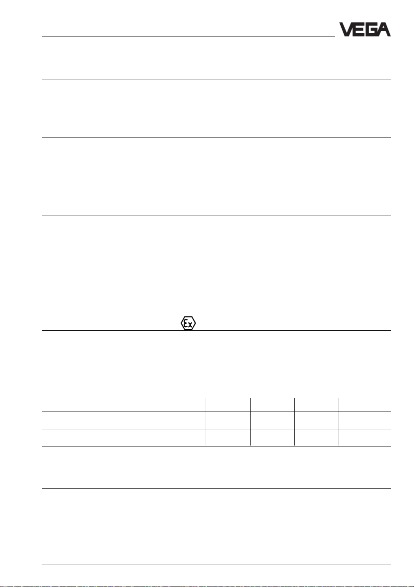
1.5 T ype plate
The type plate contains important data required for connection. The type plate is located
laterally on the multiple plug. The configuration and parts of the type plate are described in the
following:
PTB Nr. Ex-96.D.2137X
[EEx ia] IIC
specification per circuit:
U
o
I
o
P
o
18,2V
270mA
926mW
L
o
C
o
VEGA TRENN 548 V EX
0,41mH
circuit 3
83nF
circuit 2
circuit 1
4
1 Power supply
2 Signal conditioning instrument circuit
3 Branches with sensor current circuits
4 Data of each branch
®
a
: -20…+60°C IP40 (front)
VBUS to sensors
+
d 22
z 30
d 30
d 24
z 32
d 32
–
to evaluation
(MET/LOG)
–
z10
3
VBUS
+
d10
power supply
20…53AC/72VDC
L+
d2
2
6VA
N –
4W
z2
Insp.
1
VEGATRENN 548 V Ex 7
Page 8

2 Mounting
Mounting
The Ex-separator VEGATRENN 548 V Ex can
be mounted as follows:
- in carrier BGT 596 Ex or BGT LOG 571
- in housing type 506
Mounting in carrier
First of all mount the Ex-module inot your
carrier. The Ex-module consists of a multipoint
connector acc. to DIN 41 612, individual
coded pins (see drawing), a separating
chamber as well as guide rails and mounting
material.
Wire the connections of the multipoint
connectro acc. to the wiring place on the
following pages.
The multipoint connector is available as
follows:
- Wire-Wrap standard connection
1,0 x 1,0 mm
- Plug-connection 2,8 x 0,8 mm
- Termi-Point standard connection
1,6 x 0,8 mm
- Soldering connection
- Screw terminals 2 x 0,5 mm
2
Further information concerning mounting is
stated in the operating instruction of the
carrier.
Mounting in single housing
The housing socket can be either screwed
directly to a mounting plate or plugged on a
carier rail (TS 35 x 7,5 acc. to EN 50 022 or
TS 32 acc. to EN 50 035). Further information
concerning mounting are stated in the
operating instruction of the housing. Connect
the wires acc. to the wiring plan.
Coding
The multipoint connector of the carrier or the
housing must be provided with coded eys to
avoid interchanging of the various signal
conditioning instruments. The multiple plug of
VEGATRENN is povided with the appropriate
holes (mechanical coding).
The instrument coding ensures that the
various signal conditioning instruments are not
interchanged. The appropriate coded pins are
attached to each module or housing. Provide
the multipoint connector with these coded
pins acc. to the following table and figure.
The Ex-coding with fixed coded pin ensures
that not-Ex and Ex-intruments are not
interchanged.
Instrument Excoding coding
VEGATRENN 548 V Ex a25 / c11 c23
Fig. 2.1 Coding table
Instrument coding Function coding
VEGATRENN
548 V Ex
a25
z b d
a c
o 1 o
o 3 o
o 5 o
o 7 o
o 9 o
o11o
o13o
o15o
o17o
o19o
o21o
o23o
o25o
o27o
o29o
o31o
c11
c23
Safety barrier
Ex-coding
Fig. 2.2 Module coding VEGATRENN
8 VEGATRENN 548 V Ex
Page 9

Electrical connection
3 Electrical connection
3.1 Installationinformation
Generally the following instructions must be
noted for installation:
Installation place
VEGATRENN 548 V Ex as well as the
apropriate signal conditioning instrument must
be generally instaled outside the hazardous
areas.
Protection
In Ex-applications protection IP 20 must be
maintained. Cover the gaps or free modules
from the front with appropriate blind covers.
Ex-separating chamber
An Ex-separating chamber must be mounted
to the connections of VEGATRENN to ensure
sufficient „air and creeping distances“. Loop
the cable through the Ex-separating chamber
and connect the cables. Fasten the Exseparating chamber with the lower screw.
Note the operating instruction of the carrier
BGT 596 Ex.M.
Mounting in carrier
When you mount VEGATRENN in a carrier, you
have to use a VEGA-Ex-module. Keep a
distance of at least 10 mm (2 TE) to module
cards of other manufacturers. When you want
to mount VEGATRENN in the complete left
position in the carrier, a blind cover of at least
20 mm (4 TE) must be mounted in front of the
module of the instrument.
2
on
VEGATOR
Blind cover
Separation from not intrinsically safe
circuits
A separating wall must be provided between
the connection parts of intrinsically safe and
not intrinsically safe circuits so that the min.
distance of 50 mm must be kept. When using
a separating chamber (supplied with the
module) this condition is met.
General conditions
In addition the valid „Installation and operating
instructions“ as well as the special conditions
and instructions in the conformity certificates
must be noted.
VEGATRENN 548 V Ex 9
Page 10

Electrical connection
3.2 Connection instructions
Not intrinsically safe input
The not intrinsically safe input of the Exseparator is connected via a standard twowire line with a signal conditioning instrument.
If electromagnetic interferences have to be
expected, screened cable should be used.
The screen must only be earthed a one end of
the signal conditioning instrument.
Intrinsically safe output
The wiring of the intrinsically safe outputs of
the Ex-separator with the sensors must meet
with the valid installation regulations. E.g. the
DIN-regulations prescribe that the connection
lines between Ex-separator and sensors must
be marked on the entire length. For coverings
light blue must be used as colour.
If electromagnetic interferences must be
expected, screened cable must be used. The
screen must only be earthed at one sensor
end.
3.3 Wiring plan
Power
supply
VBUSconnection
of signal
conditioning
instrument
max. 5
VBUSsensors
1 … 5
max. 5
VBUSsensors
6 … 10
L (+)
N (–)
+
–
+
–
+
–
2
4
6
8
10
12
14
16
18
20
22
24
26
28
30
32
d b z
+
–
max. 5
VBUSsensors
11 … 15
10 VEGATRENN 548 V Ex
Page 11

Electrical connection
3.4 Connection examples
In conjunction with VEGALOG 571
Power
supply
L (+)
N (–)
Busverdrahtung *
Sensors
1 … 5
Sensors
6 … 10
+
–
+
–
d b z
2
4
6
8
10
12
14
16
18
20
22
24
26
28
30
32
EV-card
)
18
20
22
24
26
28
30
32
VEGATRENN
548 V Ex
d b z
2
4
6
VBUS-line
+
–
max. 5
VBUSsensors
1 … 5
max. 5
VBUSsensor
11
VBUSsensor
12
VBUSsensor
13
VBUSsensor
14
VBUSsensor
15
VBUSsensors
6 … 10
+
–
1
2
1
2
1
2
1
2
1
2
+
–
+
–
8
10
12
14
16
18
20
22
24
26
28
30
32
VEGATRENN
548 V Ex
+
–
max. 5
VBUSsensors
11 … 15
*) The connectionof sensors 1 … 5 or 6 … 10 is made in the same way.
VEGATRENN 548 V Ex 11
Page 12

In conjunction with VEGAMET 514 V and 515 V (carrier)
Electrical connection
Power
supply
L (+)
N (–)
d b z
2
4
6
8
10
12
14
16
18
20
22
24
26
28
30
32
VEGAMET
515 V
d b z
2
4
6
VBUS-line
+
–
+
–
VBUSsensor 1
+
–
8
10
12
14
16
18
20
22
24
26
28
30
32
VEGATRENN
548 V Ex
Bus wiring *
28
30
32
VEGATRENN
548 V Ex
+
VBUSsensor 2
–
)
+
–
+
–
VBUS-
1
sensor 1
2
VBUS-
1
sensor 2
2
*) only with VEGAMET 515 V
12 VEGATRENN 548 V Ex
Page 13

Electrical connection
In conjunction with VEGAMET 514 V and 515 V (housing type 506)
Power supply
Multipoint
connector for
VEGAMET
514 V/515 V
L (+)
N (–)
z6b6d6N–L+z16z18z
z10b10d
z12b12d
12
GEH506
socket
10
b22b24z
d22d24z
22
24
d16d18d
b16b18b
20
20
20
Multipoint connector for
VEGATRENN 548 V
Bus wiring
1 2 3 4 5 6 7 8
not
coordinated
+
–
1 2
VBUSsensor 1
+
–
1 2
VBUSsensor 2 *
)
1 2 3 4 5 6 7 8
not
coordinated
+
–
1 2 1 2
VBUSsensor 1
VBUSsensor 2 *
+
–
)
*) only with VEGAMET 515 V
VEGATRENN 548 V Ex 13
Page 14

Set-up, diagnosis
4 Set-up
For set-up note additionally the operating
instruction and the legal documents of the
sensors and signal conditioning instrumetns
used.
5 Diagnosis
5.1 Maintenance
The instrument is maintenance free.
5.2 Repair
Due to safety and guarantee reasons repair
work must only be done by VEGA-staff.
5.3 Fault signal
VEGATRENN 548 V Ex has no own monitoring.
The signal conditioning instrumetn circuit and
the sensor current circuits are monitored by
the signal conditioning instrument on
shortcircuit and line break.
14 VEGATRENN 548 V Ex
Page 15

Notes
VEGATRENN 548 V Ex 15
Page 16

VEGA Grieshaber KG
Am Hohenstein 113
D-77761 Schiltach
Phone (0 78 36) 50 - 0
Fax (0 78 36) 50 - 201
Fax (0 78 36) 50 - 203
ISO 9001
Technical data subject to alterations 2.20 970 / Febr. ’97
 Loading...