

Page 1
Operating Instruction
VEGATRENN 547 V Ex
Level and Pressure
on
VEGATRENN
547 V Ex
out
in
Page 2

Contents
Safety information ........................................................................ 2
1 Product description
1.1 Function, configuration and mounting ................................. 3
1.2 Technical data ...................................................................... 5
1.3 Dimensions ........................................................................... 7
1.4 Approvals ............................................................................. 7
1.5 Type plate ............................................................................. 7
2 Mounting ..................................................................................... 8
3 Electrical connection
3.1 Installation information ......................................................... 9
3.2 Connection instructions ..................................................... 10
3.3 Wiring plan ......................................................................... 10
3.4 Connection examples ........................................................ 11
4 Set-up ........................................................................................ 14
Contents
5 Diagnosis
5.1 Maintenance ....................................................................... 14
5.2 Repair ................................................................................. 14
5.3 Fault signal ......................................................................... 14
Safety information
The described module must only be installed
and operated as described in this operating
instruction. Please note that other action can
cause damage for which VEGA does not take
responsibility.
2 VEGATRENN 547 V Ex
Page 3
Product description
1 Product description
1.1 Function, configuration and mounting
Function
Ex-separator VEGATRENN 547 V Ex is used
for intrinsically safe, galvanically isolated
supply of up to two ultrasonic or radar
sensors. At the input side it is connected to
the two-wire-VBUS-line of the signal
conditioning instrument and provides at the
output side 2 x 2 ib-circuits. Each sensor is
supplied via two ib-circuits so that two
sensors can be connected to Ex-separator.
The Ex-separator can be used in conjunction
with the following signal conditioning
instruments or sensors:
- VEGAMET 514␣ V and 515␣ V
- EV-card of VEGALOG 571
- ultrasonic sensors VEGASON series 80
- radar sensors VEGAPULS series 64 and
series 80 for intrinscially safe supply “ib“.
The intrinsically safe ib-circuits are isolated as
well as from the not intrinsically safe circuits.
Configuration
Configuration
The Ex-separator VEGATRENN 547 V Ex is
designed in 19“-technology with 5 TE (= 25,4
mm). The connection is made via a multiple
plug acc. to DIN 41 612.
Mounting
There are the following mounting possibilities
- in housing type 506 with VEGAMET
- in carrier BGT 596 Ex with VEGAMET
- carrier BGT LOG 571 *) with VEGALOG
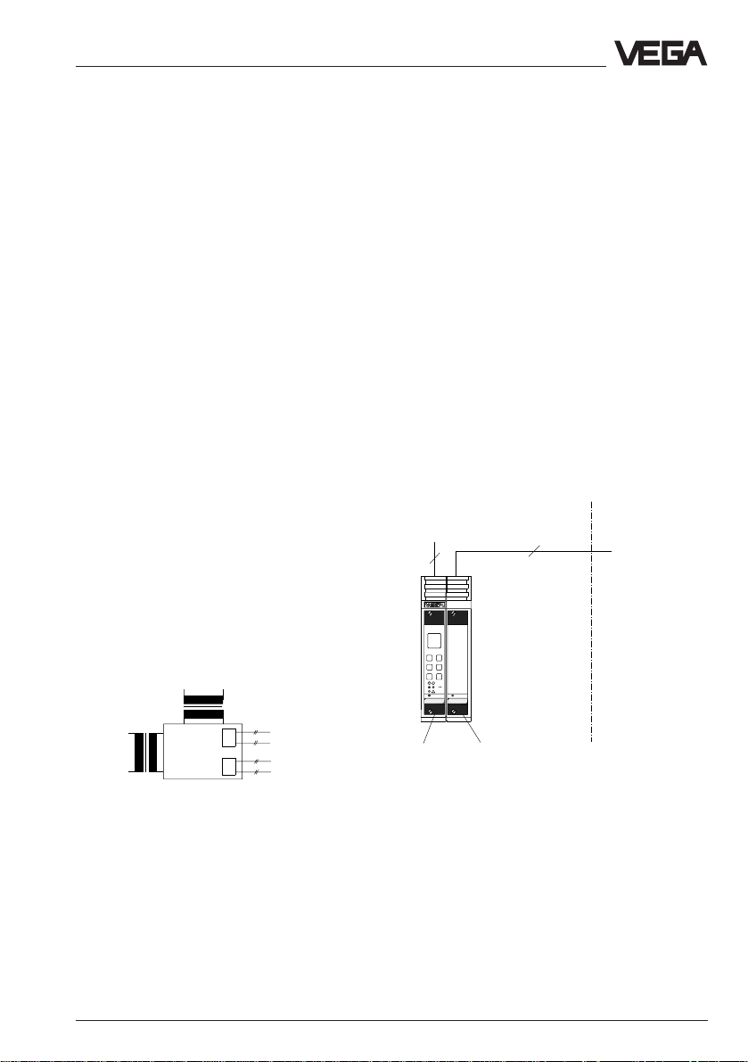
Example 1:
In housing type 506 with VEGAMET
Supply
Not-Ex-area
2
4
Ex-area
two
VBUS ib IIBcircuits per
sensor
Power supply
VEGAMET
VEGATRENN
515V
548VEx
VEGATRENN
547␣ V Ex
Signal
conditioning
instrument
(VBUS)
electronics
Intrinsically safe ibcircuits
Sensor 1
Sensor 2
VEGAMET
514␣ V
515␣ V
Fig. 1.1: Block diagram of the Ex-separator
*) If several VEGATRENN 547 V Ex are used, it is
recommended to separate them into the cheaper
BGT 596 Ex.
VEGATRENN 547 V Ex 3
Page 4
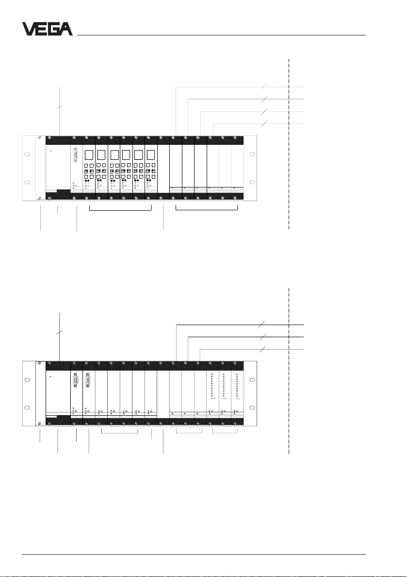
Example 2: In BGT 596 Ex M with VEGAMET 515 V
Supply
2
PC
–
–
–
+
–
+
OK
ESC
OK
ESC
BA
VEGAMET
VEGACOM
VEGASTAB
593
VEGAMET
515V
557
515V
–
+
+
–
ESC
VEGAMET
+
+
OK
ESC
OK
VEGAMET
515V
OK
ESC
OK
ESC
VEGAMET
VEGAMET
515V
515V
515V
VEGATRENNVEGATRENN
548VEx
548 V Ex
548 V Ex
Not-Ex-area
VEGATRENNVEGATRENN
VEGATRENN
548VEx
Product description
Ex-area
2 x 4
2 x 4
2 x 4
2 x 4
VEGATRENN
548 V Ex
548 V Ex
VBUS ib IIBcircuits
VEGAMET 515␣ V VEGATRENN
VEGACOM 557
Blind cover
Blind cover
Power
supply
unit
Example 3: In BGT 596 Ex M with VEGALOG
Supply
2
PC
PC
BA
BA
VEGACOM
VEGACOM
VEGALOG
VEGASTAB
Blind cover
Power
supply
unit
593
557
557
CPU
VEGACOM
557
VEGALOG
571EA
571 EA
EAcards
VEGALOG
VEGALOG
VEGALOG
EVcards
571EV
VEGATRENN
548 V Ex
VEGATRENN
547␣ V Ex
571 EA
571EA
blind cover
547␣ V Ex
VEGATRENN
548VEx
VEGATRENN
VEGALOG
548 V Ex
Not-Ex-area
1
1
2
2
3
3
4
4
5
5
6
6
7
7
8
8
9
9
10
10
VEGALOG
VEGALOG
571 EA
571EA
output
cards
Ex-area
2 x 4
2 x 4
2 x 4
1
2
3
4
5
6
7
8
9
10
571 EA
VBUS ib IIBcircuits
4 VEGATRENN 547 V Ex
Page 5
Product description
1.2 Technical data
Power supply
Operating voltage U
Power consumption approx. 13 W, approx. 18 VA
Fuse 1 A, slow-blow
Signal conditioning instrument circuit
For connection to signal conditioning instrument VEGAMET 514 V,
Input voltage U
The signal conditioning instrument circuit must only be connected to instruments with an
operating voltage less than 250 V.
Sensor circuit
Number 2 sensor circuits (both 2 ib-circuits)
Sensors Ultrasonic sensors
Voltage approx. 17 V DC at 85 mA
Current limitation electronically at approx. 85 mA, shortcircuit-proof
Connection line per sensor 4-wire (standard line) *
Resistance per conductor max. 7,5 Ω
Line length max. 500 m
= 24 V AC (20 … 53 V), 50/60 Hz
nom
= 24 V DC (20 … 72 V)
515 V or
EV-card of VEGALOG 571
= 25 V DC with VEGAMET
nom
= 24 V DC with EV-card VEGALOG
VEGASON 83 … 87 FV/GV Ex or Ex0,
radar sensors VEGAPULS 81 F/D Ex or Ex0
)
Sensor circuits, Ex-technical data
Classification [EEx ib] IIB
Max. values (per sensor circuit)
- voltage U
- current I
-eff
iciency P
Characteristics linear
Max. permissible outer inductance L
Max. permissible outer capacitance Ca296 nF
a
≤ 20,05 V
O
≤ 103 mA
O
≤ 2,05 W
O
0,7 mH
The intrinsically safe sensor current circuits are reliably galvanically isolated from the not
intrinsically safe circuits and supply up to a peak value of the nominal voltage of 375 V.
Indicating elements
LED in front plate green on: operating voltage on
*)screened cable is recommended for electromagnetic interferences.
VEGATRENN 547 V Ex 5
Page 6

Product description
Electrical connection
Multiple plug component acc. to DIN 41 612, series F, 33-pole,
3 rows d, b, z (partly equipped)
In conjunction with
- carrier
BGT 596 Ex, BGT LOG 571 connection to appropriate Ex-module
- housing tpye 506 connection to screw terminals (max. 2,5 mm2)
Protective measures
Protection
- not mounted IP 00
- mounted in BGT 596 Ex or
BGT LOG 571 front side (completely equipped):IP 40
upper and lower side: IP 20
wiring side:IP 00
- mounted in housing type 506 front side (completely equipped): IP 40
housing general: IP 30
terminal side: IP 20
Protection class (in housing type 506) II
Overvoltage category II
Electrical separating measures
Galvanic separation between intrinsically safe circuits, against
not intrinsically safe circuits as well as against
the power supply
- reference voltage 250 V
- isolation resistance 1,5 kV
CE-conformity
The ex-separator VEGATRENN 547 V Ex meets the protective regulations of EMVG (89/336/
EWG) and NSR (73/23/EWG). The conformity has been judged acc. to the following
standards:
EMVG Emission EN 50 081-2: 1993
Susceptibility EN 50 082-2: 1995
NSR EN 61 010
Mechanical data
Series module unit for 19“-carrier or housing type 506
Dimensions W = 25,4 mm (5 TE), H = 128,4 mm, D = 162 mm
Weight approx. 350 g
Ambient conditions
Permissible ambient temperature -20°C … +60°C
Storage and transport temperature -40°C … +80°C
6 VEGATRENN 547 V Ex
Page 7

Product description
1.3 Dimensions
Circuit board
100␣ x␣ 160␣ x␣ 1,5
European size
3
5,5
9
15
162
Multiple plug
5 TE
100
128,4 (3 HE)
on
25,4
1.4 Approvals
The Ex-separator VEGTRENN 547 V Ex is approved for connection of sensors in hazardous
areas. The conformity certificate to CENELEC has PTB-no. Ex-97.D.2098 X.
1.5 Type plate
The type plate contains important data required for connection. The type plate is located
laterally on the multiple plug. The configuration and parts of the type plate are described in the
following:
PTB Nr. Ex-95.D.????X
[EEx ib] IIB
specification per circuit:
U
o
I
o
P
o
20V
103mA
2,05W
L
o
C
o
VEGA TRENN 547 V EX
0,7mH
296nF
S 2
S 1
4
1 Power supply
2 Signal conditioning instrument circuit
3 Sensor circuit
4 Data of each sensor circuit
®
a
: -20…+60°C IP40 (front)
VBUS to sensors
3 +
2 –
1 +
d 22
z 20
z 18
d 30
z 32
z 30
4 –
d 24
d 32
to evaluation
z10
3
VBUS
(MET/LOG)
+
–
d10
power supply
20…53AC/72VDC
L+
d2
2
18VA
N –
13W
z2
Insp.
1
VEGATRENN 547 V Ex 7
Page 8
2 Mounting
The Ex-separator VEGATRENN 547 V Ex can
be mounted as follows:
- in carrier BGT 596 Ex or
BGT LOG 571
- in housing type 506
Mounting in carrier
First of all mount the Ex-module into your
carrier. The Ex-module consists of a multipoint
connector acc. to DIN 41 612, individual
coded pins (see coding), a separating
chamber as well as guide rails and mounting
material.
Montage
Coding
The multipoint connector of the carrier or the
housing must be provided with coded keys to
avoid interchanging of the various signal
conditioning instruments. The multiple plug of
VEGATRENN is provided with the appropriate
holes (mechanical coding).
The instrument coding ensures that the
various signal conditioning instruments are not
interchanged. The appropriate coded pins are
attached to each module or housing. Provide
the multipoint connector with these coded
pins acc. to the following table and figure.
Wire the connections of the multipoint
connector acc. to the wiring plan on the
following pages.
The multipoint connector is available as
follows:
- Wire-Wrap standard connection
1,0␣ x␣ 1,0␣ mm
- Plug connection 2,8␣ x␣ 0,8 mm
- Termi-Point standard connection
1,6␣ x␣ 0,8␣ mm
- Soldering connection
- Screw terminal 2␣ x␣ 0,5␣ mm
2
Further information concerning mounting is
stated in the operating instructions of the
carrier.
Mounting in single housing
The housing socket can be either screwed
directly to a mounting plate or plugged on a
carrier rail (TS 35 x 7,5 acc. to EN 50 022 or
TS 32 acc. to EN 50 035). Further information
concerning mounting are stated in the
operating instructions of the housing. Connect
the wires acc. to the wiring plan.
The Ex-coding with fixed coded pins ensures
that not-Ex and Ex-instruments are not
interchanged.
Instrument- Excoding coding
VEGATRENN 547 V Ex a23 / c11 c23
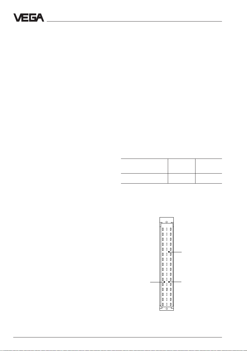
Fig. 2.1 Coding table
Instrument coding Function coding
z b d
a c
o 1 o
o 3 o
o 5 o
o 7 o
o 9 o
VEGATRENN
547 V Ex
a23
o11o
o13o
o15o
o17o
o19o
o21o
o23o
o25o
o27o
o29o
o31o
c11
c23
safety barrier
Ex-coding
Fig. 2.2 Module codingVEGATRENN
8 VEGATRENN 547 V Ex
Page 9

Electrical connection
3 Electrical connection
3.1 Installation information
Generally the following instructions must be
noted for installation:
Installation place
VEGATRENN 547 V Ex as well as the
appropriate signal conditioning instrument
must be generally installed outside the
hazardous area.
Protection
In Ex-applications protection IP 20 must be
maintained. Cover the gaps or free modules
from the front with appropriate blind covers.
Ex-separating chamber
An Ex-separating chamber must be mounted
to the connections of VEGATRENN to ensure
sufficient “air and creep distances“. Loop the
cable through the Ex-separating chamber and
connect the cables. Fasten the Ex-separating
chamber with the lower screw. Note the
operating instructions of the carrier BGT 596
Ex.M.
Mounting in carrier
When you mount VEGATRENN in a carrier,
you have to use a VEGA-Ex-module. Keep a
distance of at least 10 mm ( 2TE) to module
cards of other manufacturers. If you want to
mount VEGATRENN in the complete left
position in the carrier, a blind cover of at least
20 mm (4 TE) must be mounted in front of the
module of the instrument.
2
on
VEGATOR
Blind cover
not intrinsically safe circuits so that the min.
distance of 50 mm must be kept.
When using a separating chamber (supplied
with the module) this condition is met.
General conditions
In addition the valid “installation and operating
instructions“ as well as the special conditions
and instructions in the conformity certificates
must be noted.
Separation from not intrinscially safe
circuits
A separating wall must be provided between
the connection parts of intrinsically safe and
VEGATRENN 547 V Ex 9
Page 10

2
6
12
20
28
24
22
10
16
18
30
32
d b z
1 +
2 –
3 +
4 –
1 +
2 –
L (+)
N (–)
26
–
14
+
8
4
3 +
4 –
Electrical connection
3.2 Connection instructions
Not intrinsically safe input
The not intrinsically safe input of the Exseparator is connected via a standard twowire line with a signal conditioning instrument.
If electromagnetic interferences have to be
expected, screened cable should be used.
The screen must only be earthed at one end
of the signal conditioning instrument.
Intrinsically safe output
The wiring of the intrinsically safe outputs of
the Ex-separator with the sensors must meet
with the valid installation regulations. E.g. the
DIN-regulations prescribe that the connection
lines between Ex-separator and sensors must
be marked on the entire length. For coverings
light blue must be used as colour.
If electromagnetic interferences must be
expected, screened cable must be used. The
screen must only be earthed at one sensor.
3.3 Wiring plan
Power
supply
VBUSconnection
of signal
conditioning
instrument
VBUSsensor 2
VBUSsensor 2
VBUSsensor 1
VBUSsensor 1
10 VEGATRENN 547 V Ex
Page 11

Electrical connection
3.4 Connection examples
In conjunction with VEGALOG 571
Power
supply
+
–
d b z
2
4
6
8
10
12
14
16
18
20
22
24
26
28
30
32
EV-cards
L (+)
N (–)
Rack 1
Rack 2
VBUSSensor 2
VBUSSensor 2
3 +
4 –
1 +
2 –
d b z
2
4
6
8
10
12
14
16
18
20
22
24
26
28
30
32
VEGATRENN
547 V Ex
No. 1
VBUS-line
3 +
VBUSSensor 1
4 –
1 +
VBUSSensor 1
2 –
VBUSSensor 2
VBUSSensor 2
+
–
3 +
4 –
1 +
2 –
d b z
2
4
6
8
10
12
14
16
18
20
22
24
26
28
30
32
VEGATRENN
547 V Ex
No. 2 …
3 +
VBUSSensor 1
4 –
1 +
VBUSSensor 1
2 –
VBUSSensor
2
VBUSSensor 2
+
–
3 +
4 –
1 +
2 –
d b z
2
4
6
8
10
12
14
16
18
20
22
24
26
28
30
32
VEGATRENN
547 V Ex
… No. 8
3 +
4 –
1 +
2 –
VBUSSensor
1
VBUSSensor 1
conne tion of sensors 1 … 15
VEGATRENN 547 V Ex 11
Page 12

In conjunction with VEGAMET 515 V (carrier)
Electrical connection
Power
supply
L (+)
N (–)
d b z
2
4
6
8
10
12
14
16
18
20
22
24
26
28
30
32
VEGAMET
515␣ V
+
–
VBUS
VBUS-line
VBUSSensor 1
VBUSSensor 1
d b z
2
4
6
+
–
3 +
4 –
1 +
2 –
8
10
12
14
16
18
20
22
24
26
28
30
32
VEGATRENN
547 V Ex
3 +
4 –
1 +
2 –
VBUSSensor 2
VBUSSensor 2
12 VEGATRENN 547 V Ex
Page 13

Electrical connection
In conjunction with housing type 506
power supply
multipoint
connector
für VEGAMET
514 V / 515 V
L (+)
N (–)
z6b6d6N–L+z16z18z
z10b10d
b22b24z
10
z12b12d
d22d24z
12
GEH506
socket
1 2 3 4 5 6 7 8
3
1
2
1
2
4
1
2
22
24
5
b16b18b
d16d18d
3
20
20
20
multipoint connector for
VEGATRENN 547 V Ex
6
7
8
3
4
4
sensor number
VBUSSensor 1
VBUSSensor 2 *
)
*) only with VEGAMET 515 V
VEGATRENN 547 V Ex 13
Page 14

Set-up, diagnosis
4 Set-up
For set-up note additionally the operating
instructions and the legal documents of the
sensors and signal conditioning instruments
used.
5 Diagnosis
5.1 Maintenance
The instrument is maintenance free.
5.2 Repair
Due to safety and guarantee reasons repair
work must only be done by VEGA-staff.
In case of defect please return the respective
instrument with a short description of the error
to our repair department.
5.3 Fault signal
VEGATRENN 547 V Ex has no own monitoring.
The sensor lines are monitored by the signal
conditioning instrument on shortcircuit and
line break.
14 VEGATRENN 547 V Ex
Page 15

Notes
VEGATRENN 547 V Ex 15
Page 16

VEGA Grieshaber KG
Am Hohenstein 113
D-77761 Schiltach
Phone (0 78 36) 50 - 0
Fax (0 78 36) 50 - 201
e-mail vega@vega-g.de
ISO 9001
Technical data subject to alterations 2.20 965 / Jan. ’98
 Loading...