

Page 1
Operating Instruction
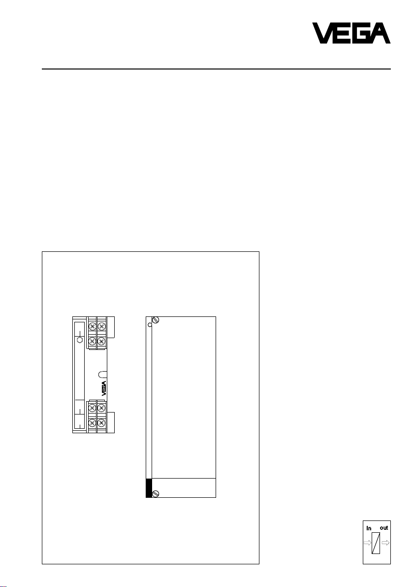
Safety barrier type 146
VEGATRENN 546
IN
+12–
11
Ex
1211
Level and Pressure
Trennübertrager Typ 146
[EEx ib] IIB PTB Nr. Ex-93.C.4025
OUT 1
+
–
2
1
2
1
OUT 2
+4–
3
3
4
VEGATRENN 546
out
in
Page 2

Contents
Safety information ........................................................................................ 2
1 Product description
1.1 Function and configuration ................................................................. 3
1.2 Types .................................................................................................. 3
1.3 Technical data ..................................................................................... 4
1.4 Dimensions ......................................................................................... 5
1.5 Approvals ............................................................................................ 6
1.6 Type plate ........................................................................................... 6
2 Mounting .................................................................................................. 6
3 Electrical connection
3.1 Erection instructions ........................................................................... 7
3.2 Wiring instruction ................................................................................ 7
3.3 Wiring plan .......................................................................................... 7
3.4 Wiring examples ................................................................................. 8
4 Set-up ........................................................................................................ 8
Contents
Safety information
The described module must only be inser ted and
operated as described in this operating instruction.
Please note that other action can cause damage for
which VEGA does not take responsibility.
2 Safety barrier type 146, VEGATRENN 546
Page 3
Product description
1 Product description
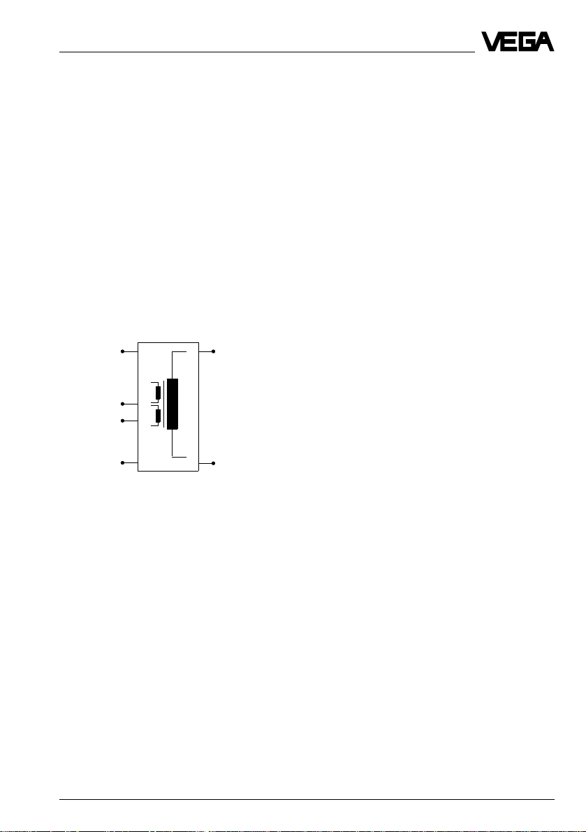
1.1 Function and configuration
The safety barrier type 146 as well as VEGATRENN
546 are used for intrinsically safe, galvanically
separated supply and for signal transmission for the
following VBUS-sensors
- VEGASON 8. FV Ex / Ex0
- VEGAPULS 64 .V Ex / Ex0.
For this purpose the not-intrinsically safe circuit of the
respective VBUS-signal conditioning instrument is
converted into two intrinsically safe ib-circuits..
The above mentioned sensors can be connected to
the following signal conditioning instruments via safety
barrier type 146 or VEGATRENN 546
- VEGAMET 407 V, 509 V, 514 V and 515 V
- EV-card of VEGALOG 571
ib-circuit to the
sensor
not-intrinsically safe
circuit to the signal
conditioning
instrument
ib-circuit to the
sensor
Fig. 1.1 Block diagram
1.2 Types
The function of both types is identical, only the
mechanical configuration and the electrical
connection are different.
Safety barrier type 146
The electronics is located in a plastic housing. On the
front side on top there are two screw terminals for the
input and on bottom four screw terminals for the
outputs. The intrinsically safe output circuits are
marked blue on the type plate. On the back of the
instrument an adapter for snap-in fastening on carrier
rail 35 x 7,5 mm (C-profile) acc. to EN 50 022 is
located.
VEGA TRENN 546
A complete safety barrier type 146 is mounted on a
19"-module card in European size. The connection is
made via a multipoint plug DIN 41 612. VEGATRENN
546 is provided for use in a 19"-carrier type 596 Ex on
a respectively equipped Ex-module or in a plastic
housing type 589-10 Ex.
The safety barriers provide the galvanic separation
between:
- the not-intrinsically safe circuits and the intrinsically
safe circuits
- among the intrinsically safe circuits.
The power required for operation is taken from the
signal circuit of the respective signal conditioning
instrument, a separate external energy is not
necessary.
Safety barrier type 146, VEGATRENN 546 3
Page 4

Product description
1.3 Technical data
Input circuit
For connection to signal conditioning instrument VEGAMET 407 V, 509 V,
Input voltage U
The input circuit must only be connected to instruments with an operating voltage smaller than 250 V.
Output circuit
Number 2
Flame proofing EEx ib IIB (intrinsic safety)
Max. values (per circuit)
- voltage U
- current I
- power P ≤ 2,33 W
Max. permissible outer inductance 1 mH
Max. permissible outer capacitance 580 nF
Resistor per line pair max. 15 Ω
Characteristics linear
Conformity certificate PTB-no. Ex-93.C.4025
The intrinsically safe output circuits are reliably galvanically separated fron the not-intrinsically safe input
circuits up to a peak value of the nominal voltage of 375 V.
514 V, 515 V or EV-card of VEGALOG 571
= 24 V DC (24 … 36 V DC)
nenn
≤ 25,2 V
O
≤ 370 mA
K
Electrical connection type 146
Terminals max. 1,5 mm
2
Electrical connection VEGATRENN 546
Multipoint plug acc. to DIN 41 612, series F, 32-pole, d, z
In conjunction with
- carrier type 596 Ex connection to respective Ex-module
- housing type 589-10 Ex connection to screw terminals (max. 1,5 mm
Protective measures
Protection unassembled
- housing IP 30
- screw terminals IP 20
- multipoint plug IP 00
Protection mounted
- housing type 589-10 Ex IP 30
- carrier BGT 596 Ex
front side (completely equipped) IP 30
upper / lower side IP 20
Protection class (in housing type 589-10 Ex) II
Electrical separating measures
Galvanic separation between intrinsically safe circuits and not-intrinsically
safe circuits as well as among the intrinsically safe circuits
- limit voltage 250 V
- test voltage 1,5 kV
2
)
4 Safety barrier type 146, VEGATRENN 546
Page 5

Product description
CE-conformity
The safety barrier type 146 as well as VEGATRENN 546 meet with the requirements of EMVG
(89/336/EWG). The conformity was judged acc. to the following standards:
EMVG Emission EN 50081
Immission EN 50082
Mechanical data type 146
Series housing for mounting on carrier rail 35 x 7,5 mm
(C-profile) acc. to EN 50 022
Weight appr. 250 g
Mechanical data VEGATRENN 546
Series module unit for carrier BGT 596 Ex
Dimensions W = 50,8 mm (10 TE), H = 128,4 mm, D = 162 mm
Weight appr. 350 g
Ambient conditions
Permissible ambient temperature -20°C … +50°C
Storage and transport temperature -20°C … +70°C
1.4 Dimensions
Safety barrier 146
13,5
84
42
126
15
25
5
VEGA TRENN 546
Circuit board 100 x 160 x 1,5
European size
4
12
Safety barrier type 146, VEGATRENN 546 5
Safety barrier type 146
162
Multipoint plug
100
10 TE
128,4
50,8
Page 6

2 Mounting
Product description / Mounting
1.5 Approvals
Both safety barriers are approved for connection of
sensors in hazardous areas.
The conformity certificate has the number: PTB-no.
Ex-93.C.4025.
The above mentioned certificate is issued for safety
barrier type 146 however is valid for both instruments.
1.6 Type plate
The type plate includes important data which are
required for connection. The type plate is located on
the right housing side. The configuration and parts of
the type plate are explained in the following example.
Configuration of the type plate
(Example: Safety barrier type 146)
Safety barrier 146
PTB no. Ex-93.C.4025 [EEx ib] IIB
1
Input: UM 250V UE 24V
2
Outputs: 2 galv.separated circuits
per circuit: Umax. 25,2V, IK 370mA, Pmax 2,33W
Protection: IP20
1 not-intrinsically safe cir cuit
2 intrinsically safe circuits
3 series number
Fig. 1.2 Type plate
characteristics linear
ϑa -20 … +50°C
ser. no. 10612892
3
Safety barrier type 146
The safety barrier type 146 is used for fastening on
carrier rail 35 x 7,5 mm (C-profile) acc. to EN 50 022.
VEGA TRENN 546
VEGATRENN 546 is designed as module card in
European size (DIN 41 612) and for mounting into the
VEGA 19"-carrier BGT 596 Ex.
Coding
(only for VEGATRENN 546)
A mechanical coding in form of a pin in the multipoint
connector and a hole in the multipoint plug ensures
that in case a module card is exchanged, only the
correct card type is inserted. The pin (attached) is
supplied with the module and must be inserted into
the card specific position in the hole when the module
is installed.
A function coding with fixed coded pin ensures that Ex
and not-Ex- module cards are not exchanged.
Function coding
d b z
a c
o 1 o
o 3 o
o 5 o
o 7 o
o 9 o
o 11 o
o 13 o
o 15 o
o 17 o
o 19 o
o 21 o
c23
o 23 o
o 25 o
o 27 o
o 29 o
o 31 o
Ex-module card
Fig. 2.1 Multipoint connector
6 Safety barrier type 146, VEGATRENN 546
Page 7

Electrical connection
3 Electrical connection
3.1 Erection instructions
Please observe the following instructions for erection:
- Parts of the measuring system are subjected to the
special conditions and information in the conformity
certificates (the respective conformity certificates
are attached to the instruments).
- VEGATRENN 546 must be erected such that a
protection of at leat IP 20 acc. to IEC 144 (529) is
reached. Due to respective installation in a carrier
BGT 596 Ex of VEGA and respective installation of
the carrier, the requirement is met.
- Between the connection parts of intrinsically safe
and not-intrinsically safe circuits a separation wall
must be provided, so that a min. distance of 50 mm
is ensured. By using module type 596 Ex of VEGA
this requirement is met.
- If VEGALOG 571 with EV-input card is used as
signal conditioning instrument, max. 5 safety
barriers can be connected.
- Safety barrier and signal conditioning instrument
must only be used outside hazardous areas.
- Only one sensor must be connected to each safety
barrier.
In addition the respectively valid errection and
operating regulations must be observed. E.g. the
DIN/VDE-regulations prescribe that the connection
lines between safety barrier and sensor must be
permanently marked along their entire length. If
covers are coloured, light-blue must be used.
3.2 Wiring instruction
The not intrinsically safe input of the safety barrier is
connected via a standard two-wire line to the signal
conditioning instrument. If electromagnetic
interferences have to be expected, screened cable
should be used. The screen should only be earthed at
one end of the signal conditioning instrument.
The wiring of the intrinsically safe outputs of the safety
barrier with radar or pulse-echo sensors (in hazardous
areas) must be carried out acc. to the valid erection
regulations. Furthermore the special conditions and
information in the conformity certificates must be
observed.
3.3 Wiring plan
Safety barrier type 146
Screw terminals
IN
+
–
11
12
–12+
11
Ex
OUT 1
+
–
1
2
OUT 2
–
+
4
3
VEGA TRENN 546
Multipoint plug
10
12
14
16
18
20
22
24
26
28
30
32
+1–
+3–
d b z
2
4
6
8
+
not intrinsically safe input circuit
–
(from signal conditioning
instrument)
+
intrinsically safe output circuit 1
–
(to the sensor)
2
4
+
intrinsically safe output circuit 2
–
(to the sensor)
+
–
+
–
+
–
not intrinsically safe input circuit
(from signal conditioning
instrument)
intrinsically safe output circuit 2
(to the sensor)
intrinsically safe output circuit 1
(to the sensor)
Safety barrier type 146, VEGATRENN 546 7
Page 8

3.4 Wiring examples
Example for VEGAMET
Ex-area
Electrical connection / Set-up
Not-Ex-area
d b z
2
2
3
1
4
Intrinsically safe
circuit 1
Intrinsically safe
circuit 2
4
6
8
10
12
14
16
18
20
22
24
26
28
30
+
32
–
+
–
Not intrinsically
safe circuit
+
–
d b z
2
4
6
8
10
12
14
16
18
20
22
24
26
28
30
+
–
32
VEGAMET 514 V
VEGATRENN 546
The connection to the EV-card of VEGALOG is the same.
4 Set-up
For set-up please observe additionally the operating instruction and the legal documents of the used sensors
and signal conditioning instruments.
Important
The adjustment of the signal conditioning instrument must be made with connected safety barrier.
VEGA Grieshaber KG
Am Hohenstein 113
D-77761 Schiltach
Phone (0 78 36) 50 - 0
Fax (0 78 36) 50 - 201
Fax (0 78 36) 50 - 203
ISO 9001
Technical data subject to alterations 2.16 823 / Jan. ’96
 Loading...