

Page 1
DE
Betriebsanleitung
EN
Operating Instructions
FR
Mise en service
ES
Instrucciones de servicio
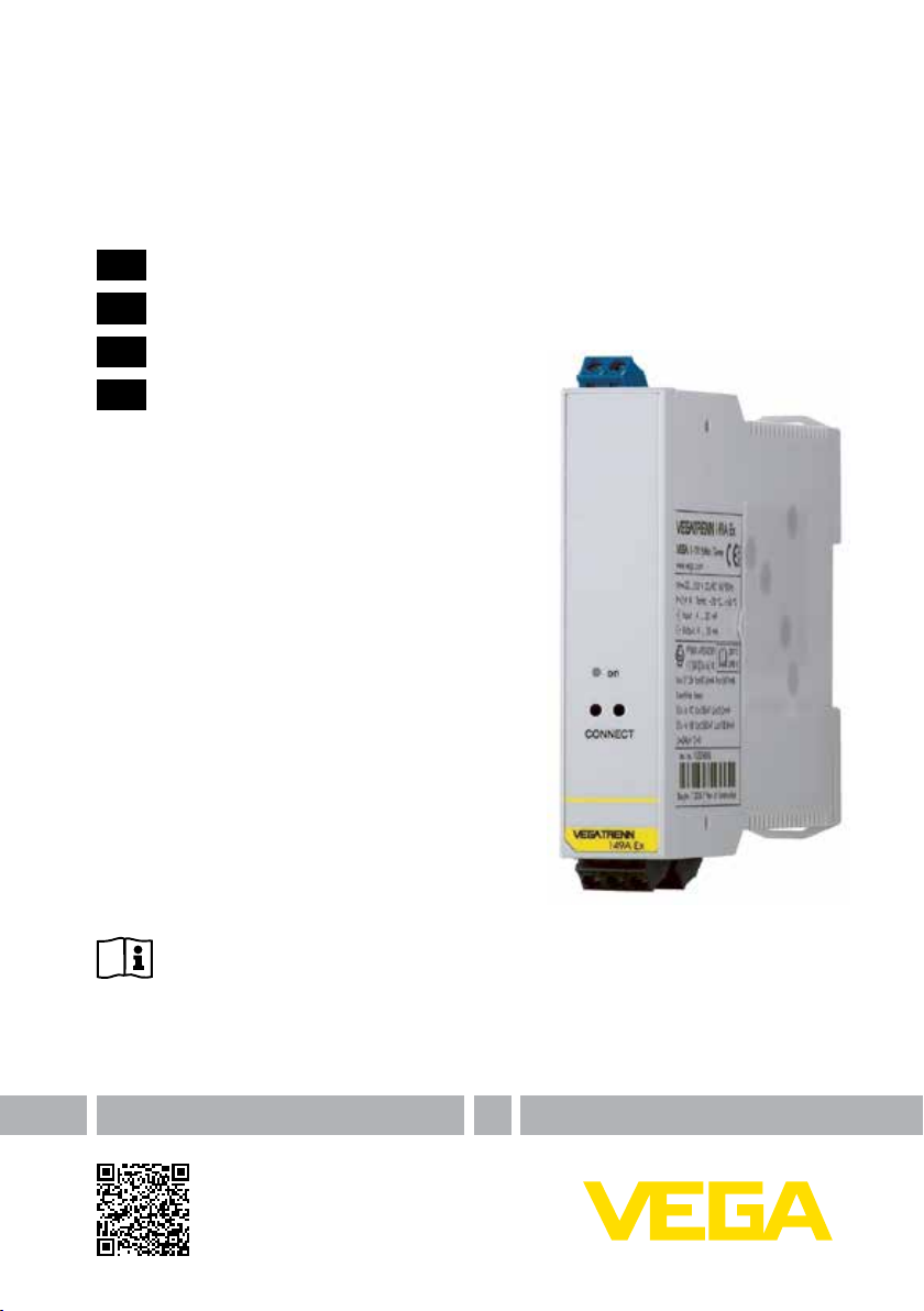
VEGATRENN 149A Ex
Document ID: 24816
Page 2

Inhaltsverzeichnis
Betriebsanleitung
Betriebsanleitung 2
DE
Operating Instructions 12
EN
Inhaltsverzeichnis
Mise en service 22
FR
Instrucciones de servicio 32
ES
1 Zu diesem Dokument
1.1 Funktion ..............................................3
1.2 Zielgruppe ...........................................3
1.3 Verwendete Symbolik .........................3
2 Zu Ihrer Sicherheit
2.1 Autorisiertes Personal .........................3
2.2 Bestimmungsgemäße Verwendung ......
3
2.3 Warnung vor Fehlgebrauch ................. 3
2.4 Allgemeine Sicherheitshinweise ..........3
2.5 CE-Konformität ...................................4
2.6 Sicherheitshinweise für Ex-Bereiche .....
4
2.7 Umwelthinweise ..................................4
3 Produktbeschreibung
3.1 Aufbau ................................................4
3.2 Arbeitsweise........................................4
3.3 Bedienung ...........................................5
3.4 Verpackung, Transport und Lagerung ...
5
4 Montieren
4.1 Montagehinweise ................................5
5 An die Spannungsversorgung anschlie-
ßen
5.1 Anschluss vorbereiten .........................5
5.2 Anschlussschritte ................................6
5.3 Anschlussplan .....................................6
6 In Betrieb nehmen
6.1 Bedienung ...........................................7
6.2 Funktionsanzeige ................................7
7 Instandhalten und Störungen beseitigen
7.1 Wartung ..............................................7
7.2 Störungen beseitigen ..........................7
7.3 Das Gerät reparieren...........................8
8 Ausbauen
8.1 Ausbauschritte ....................................8
8.2 Entsorgen............................................8
9 Anhang
9.1 Technische Daten ...............................9
9.2 Maße .................................................11
24816-01-131025
Redaktionsstand: 2013-09-25
2
VEGATRENN 149A Ex • Ex-Speisetrenner für 4 … 20 mA/HART
Page 3
2 Zu Ihrer Sicherheit
1 Zu diesem Dokument
1.1 Funktion
Die vorliegende Betriebsanleitung liefert Ihnen
die erforderlichen Informationen für Montage,
Anschluss und Inbetriebnahme sowie wichtige
Hinweise für Wartung und Störungsbeseitigung.
Lesen Sie diese deshalb vor der Inbetriebnahme und bewahren Sie sie als Produktbestandteil in unmittelbarer Nähe des Gerätes jederzeit
zugänglich auf.
1.2 Zielgruppe
Diese Betriebsanleitung richtet sich an ausgebildetes Fachpersonal. Der Inhalt dieser
Anleitung muss dem Fachpersonal zugänglich
gemacht und umgesetzt werden.
1.3 Verwendete Symbolik
Information, Tipp, Hinweis
Dieses Symbol kennzeichnet hilfreiche
Zusatzinformationen.
Vorsicht: Bei Nichtbeachten dieses
Warnhinweises können Störungen oder
Fehlfunktionen die Folge sein.
Warnung: Bei Nichtbeachten dieses
Warnhinweises kann ein Personenschaden und/oder ein schwerer Geräteschaden die Folge sein.
Gefahr: Bei Nichtbeachten dieses
Warnhinweises kann eine ernsthafte
Verletzung von Personen und/oder eine
Zerstörung des Gerätes die Folge sein.
Ex-Anwendungen
Dieses Symbol kennzeichnet besondere
Hinweise für Ex-Anwendungen.
Liste
•
Der vorangestellte Punkt kennzeichnet
eine Liste ohne zwingende Reihenfolge.
Handlungsschritt
→
Dieser Pfeil kennzeichnet einen einzelnen Handlungsschritt.
1 Handlungsfolge
Vorangestellte Zahlen kennzeichnen
aufeinander folgende Handlungsschritte.
Batterieentsorgung
Dieses Symbol kennzeichnet besondere
Hinweise zur Entsorgung von Batterien
und Akkus.
24816-01-131025
VEGATRENN 149A Ex • Ex-Speisetrenner für 4 … 20 mA/HART
2 Zu Ihrer Sicherheit
2.1 Autorisiertes Personal
Sämtliche in dieser Betriebsanleitung beschriebenen Handhabungen dürfen nur durch ausgebildetes und vom Anlagenbetreiber autorisiertes
Fachpersonal durchgeführt werden.
Bei Arbeiten am und mit dem Gerät ist immer
die erforderliche persönliche Schutzausrüstung
zu tragen.
2.2 Bestimmungsgemäße
Das VEGATRENN 149A Ex ist ein [EEx ia] Speisetrenner mit separater Spannungsversorgung
zum Anschluss von 4 … 20 mA/HART-Sensoren
in Zweileiterausführung.
Detaillierte Angaben zum Anwendungsbereich
nden Sie im Kapitel "Produktbeschreibung".
Die Betriebssicherheit des Gerätes ist nur bei
bestimmungsgemäßer Verwendung entsprechend den Angaben in der Betriebsanleitung
sowie in den evtl. ergänzenden Anleitungen
gegeben.
Eingrie über die in der Betriebsanleitung
beschriebenen Handhabungen hinaus dürfen
aus Sicherheits- und Gewährleistungsgründen
nur durch vom Hersteller autorisiertes Personal
vorgenommen werden. Eigenmächtige Umbauten oder Veränderungen sind ausdrücklich
untersagt.
2.3 Warnung vor Fehlgebrauch
Bei nicht sachgerechter oder nicht bestimmungsgemäßer Verwendung können von die-
sem Gerät anwendungsspezische Gefahren
ausgehen, so z. B. ein Überlauf des Behälters
oder Schäden an Anlagenteilen durch falsche
Montage oder Einstellung.
2.4 Allgemeine
Das Gerät entspricht dem Stand der Technik
unter Beachtung der üblichen Vorschriften und
Richtlinien. Es darf nur in technisch einwandfreiem und betriebssicherem Zustand betrieben
werden. Der Betreiber ist für den störungsfreien
Betrieb des Gerätes verantwortlich.
Verwendung
Sicherheitshinweise
3
Page 4

3 Produktbeschreibung
Der Betreiber ist ferner verpichtet, während der
gesamten Einsatzdauer die Übereinstimmung
der erforderlichen Arbeitssicherheitsmaßnahmen mit dem aktuellen Stand der jeweils
geltenden Regelwerke festzustellen und neue
Vorschriften zu beachten.
Durch den Anwender sind die Sicherheitshinweise in dieser Betriebsanleitung, die lan-
desspezischen Installationsstandards sowie
die geltenden Sicherheitsbestimmungen und
Unfallverhütungsvorschriften zu beachten.
Eingrie über die in der Betriebsanleitung
beschriebenen Handhabungen hinaus dürfen
aus Sicherheits- und Gewährleistungsgründen
nur durch vom Hersteller autorisiertes Personal
vorgenommen werden. Eigenmächtige Umbauten oder Veränderungen sind ausdrücklich
untersagt.
Weiterhin sind die auf dem Gerät angebrachten Sicherheitskennzeichen und -hinweise zu
beachten.
2.5 CE-Konformität
Das Gerät erfüllt die gesetzlichen Anforderun-
gen der zutreenden EG-Richtlinien. Mit dem
CE-Zeichen bestätigen wir die erfolgreiche
Prüfung.
Die CE-Konformitätserklärung nden Sie im
Downloadbereich unserer Homepage.
Kapitel "Verpackung, Transport und Lage-
•
rung"
Kapitel "Entsorgen"
•
3 Produktbeschreibung
3.1 Aufbau
Lieferumfang
Der Lieferumfang besteht aus:
Speisetrenner VEGATRENN 149A Ex
•
Dokumentation
•
– Dieser Betriebsanleitung
– Ex-spezischen "Sicherheitshinweisen" (je
nach Ausführung)
– Ggf. weiteren Bescheinigungen
Typschild
Das Typschild enthält die wichtigsten Daten zur
Identikation und zum Einsatz des Gerätes:
Artikelnummer
•
Seriennummer
•
Technische Daten
•
Artikelnummern Dokumentation
•
Die Seriennummer des Gerätes auf dem Typschild ermöglicht es Ihnen, die Auftragsdaten
und die Dokumentation des Gerätes abzurufen.
Gehen Sie hierzu auf www.vega.com, "VEGA
Tools" und "serial number search".
2.6 Sicherheitshinweise für
Ex-Bereiche
Beachten Sie bei Ex-Anwendungen die Ex-
spezischen Sicherheitshinweise. Diese sind
Bestandteil der Betriebsanleitung und liegen
jedem Gerät mit Ex-Zulassung bei.
2.7 Umwelthinweise
Der Schutz der natürlichen Lebensgrundlagen
ist eine der vordringlichsten Aufgaben. Deshalb
haben wir ein Umweltmanagementsystem
eingeführt mit dem Ziel, den betrieblichen
Umweltschutz kontinuierlich zu verbessern.
Das Umweltmanagementsystem ist nach
DIN EN ISO 14001 zertiziert.
Helfen Sie uns, diesen Anforderungen zu entsprechen und beachten Sie die Umwelthinweise
in dieser Betriebsanleitung:
4
VEGATRENN 149A Ex • Ex-Speisetrenner für 4 … 20 mA/HART
3.2 Arbeitsweise
Anwendungsbereich
Das VEGATRENN 149A Ex ist ein [EEx ia] Speisetrenner mit separater Spannungsversorgung
zum Anschluss von 4 … 20 mA/HART-Sensoren
in Zweileiterausführung. Als zugehöriges elektrisches Betriebsmittel stellt es eine galvanische
Trennung zwischen Sensorstromkreis und Auswertstromkreis und dadurch zwischen Ex- und
Nicht-Ex-Bereich sicher.
Funktionsprinzip
Eine eingebaute Messumformerspeisung versorgt den angeschlossenen Sensor mit Energie.
Der vom Sensor geprägte Strom (4 … 20 mA)
wird linear und galvanisch getrennt zum Ausgang übertragen. Die frontseitig eingebauten
HART-Kommunikationsbuchsen ermöglichen
eine bidirektionale Übertragung von HARTSignalen.
24816-01-131025
Page 5

4 Montieren
Spannungsversorgung
Weitbereichnetzteil mit 20 … 253 V AC/DC zum
weltweiten Einsatz.
Detaillierte Angaben zur Spannungsversorgung
nden Sie im Kapitel "Technische Daten".
3.3 Bedienung
Am VEGATRENN 149A Ex selbst gibt es
keinerlei Bedienelemente. Über die HART-Kommunikationsbuchsen kann eine Parametrierung
der angeschlossenen Sensoren vorgenommen
werden. Die Bedienung der angeschlossenen
Sensoren erfolgt vorzugsweise über einen
Windows-PC mit einer Parametrierungssoftware
wie PACTware und entsprechendem DTM.
3.4 Verpackung, Transport und
Lagerung
Verpackung
Ihr Gerät wurde auf dem Weg zum Einsatzort durch eine Verpackung geschützt. Dabei
sind die üblichen Transportbeanspruchungen
durch eine Prüfung in Anlehnung an ISO 4180
abgesichert.
Bei Standardgeräten besteht die Verpackung
aus Karton, ist umweltverträglich und wieder
verwertbar. Bei Sonderausführungen wird zusätzlich PE-Schaum oder PE-Folie verwendet.
Entsorgen Sie das anfallende Verpackungsmaterial über spezialisierte Recyclingbetriebe.
Transport
Der Transport muss unter Berücksichtigung der
Hinweise auf der Transportverpackung erfolgen.
Nichtbeachtung kann Schäden am Gerät zur
Folge haben.
Transportinspektion
Die Lieferung ist bei Erhalt unverzüglich auf Vollständigkeit und eventuelle Transportschäden zu
untersuchen. Festgestellte Transportschäden
oder verdeckte Mängel sind entsprechend zu
behandeln.
Lagerung
Die Packstücke sind bis zur Montage verschlossen und unter Beachtung der außen
angebrachten Aufstell- und Lagermarkierungen
aufzubewahren.
Packstücke, sofern nicht anders angegeben,
nur unter folgenden Bedingungen lagern:
24816-01-131025
VEGATRENN 149A Ex • Ex-Speisetrenner für 4 … 20 mA/HART
Nicht im Freien aufbewahren
•
Trocken und staubfrei lagern
•
Keinen aggressiven Medien aussetzen
•
Vor Sonneneinstrahlung schützen
•
Mechanische Erschütterungen vermeiden
•
Lager- und Transporttemperatur
Lager- und Transporttemperatur siehe Kapi-
•
tel "Anhang - Technische Daten - Umgebungsbedingungen"
Relative Luftfeuchte 20 … 85 %
•
4 Montieren
4.1 Montagehinweise
Das VEGATRENN 149A Ex ist für Tragschie-
nenmontage (Hutschiene 35 x 7,5 nach DIN
EN 50022/60715) konstruiert. Durch die Schutzart IP 20 ist das Gerät zum Einbau in Schaltschränken vorgesehen.
5 An die Spannungsversor-
5.1 Anschluss vorbereiten
Sicherheitshinweise beachten
Beachten Sie grundsätzlich folgende Sicherheitshinweise:
Nur in spannungslosem Zustand anschlie-
•
ßen
Falls Überspannungen oder Spannungs-
•
spitzen zu erwarten sind, Überspannungsschutzgeräte installieren
Sicherheitshinweise für Ex-Anwendungen
beachten
Das VEGATRENN 149A Ex ist ein zugehöriges eigensicheres Betriebsmittel
und darf nicht in explosionsgefährdeten
Bereichen installiert werden. Ein gefahrloser Betrieb ist nur bei Beachtung
der Betriebsanleitung und der EG-Baumusterprüfbescheinigung gewährleistet.
Das VEGATRENN 149A Ex darf nicht
geönet werden.
Beim Einbau muss ein Abstand von
50 mm (Fadenmaß) zu den eigensicheren Klemmen gewährleitet sein.
gung anschließen
In explosionsgefährdeten Bereichen
müssen die entsprechenden Vorschriften, Konformitäts- und Baumusterprüf-
5
Page 6
5 An die Spannungsversorgung anschließen
bescheinigungen der Sensoren und der
Versorgungsgeräte beachtet werden.
5.2 Anschlussschritte
Spannungsversorgung
Stellen Sie sicher, dass die Spannung mit den
Angaben auf dem Typschild übereinstimmt.
Im Spannungsbereich von 90 … 253 V AC muss
in Gerätenähe in der Zuleitung ein als Trennvorrichtung gekennzeichneter, leicht zugänglicher
Schalter sowie eine Überstromschutzeinrich-
tung (Nennstrom ≤ 10 A) angebracht werden.
L/+
N/-
L/+
N/-
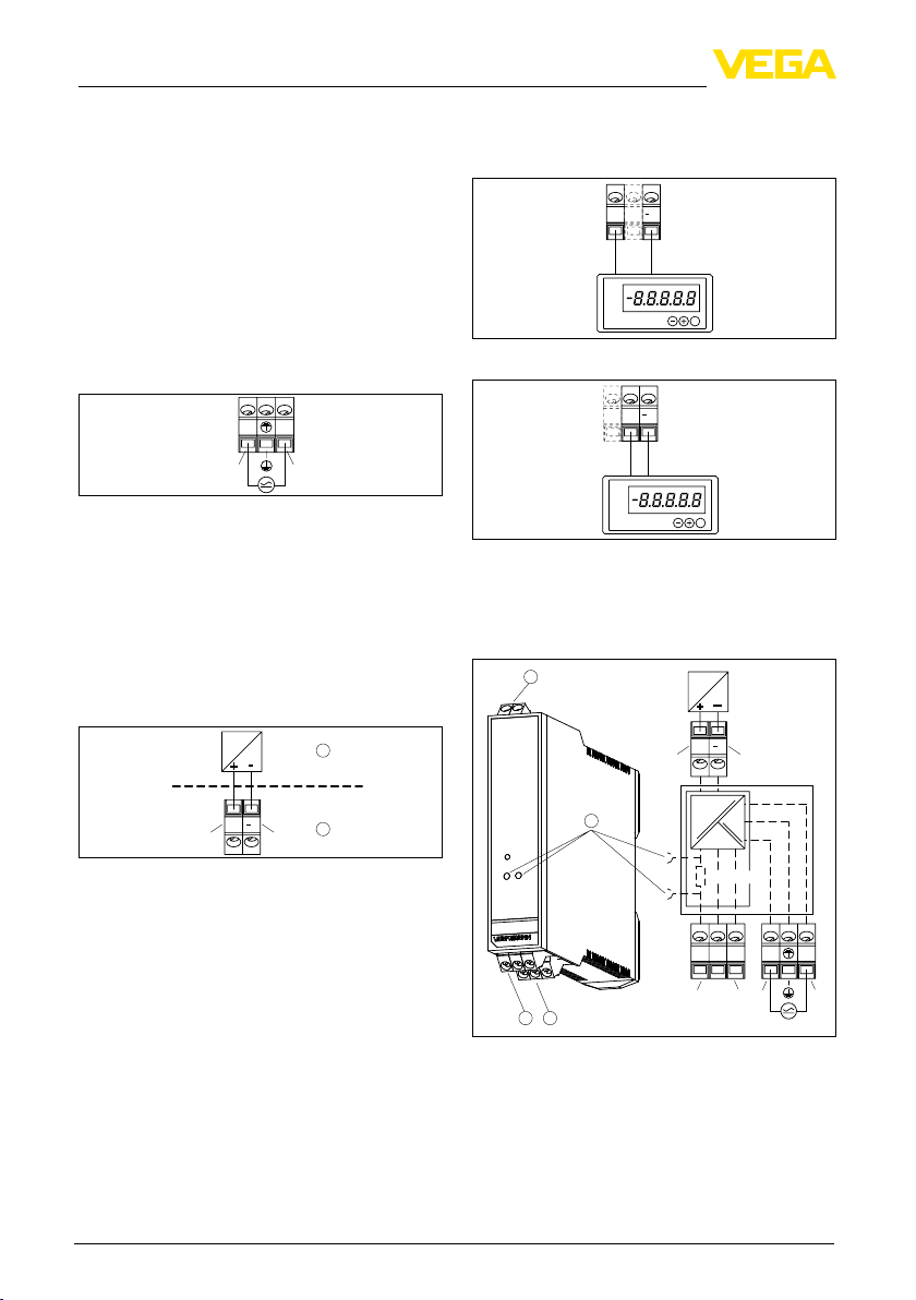
Abb. 1: Anschluss Spannungsversorgung
Sensorstromkreis (Ex-Bereich)
Der Sensor muss an die blauen Anschlussklemmen I+ und I- angeschlossen werden. Der Sensorstromkreis des Speisetrenners VEGATRENN
149A Ex ist vom Auswertstromkreis getrennt.
Der Sensorstromkreis ist aktiv, das bedeutet der
angeschlossene Sensor wird vom VEGATRENN
149A Ex mit Energie versorgt.
-
+
1
Beachten Sie, dass sich hierbei die max. anschließbare Bürde bzw. der Lastwiderstand ver-
ringert (siehe "Technische Daten" im "Anhang").
0 +0
0+H
0+
0-
Hart
VEGADIS 175
OK
Abb. 3: Anschlussbeispiel mit HART-Kommunikation
0 +0
0+H
0+ 0-
VEGADIS 175
OK
Abb. 4: Anschlussbeispiel ohne HART-Kommunikation
5.3 Anschlussplan
Klemmenbelegung
1
+
–
+I
I
I+
I–
I +I
I+
2
I-
Abb. 2: Anschluss Sensorstromkreis
1 Ex-Bereich
2 Nicht-Ex-Bereich
Auswertstromkreis (Nicht-Ex-Bereich)
An die Klemmen O+/O-/O+H werden Auswertsysteme, z. B. ein Anzeigeinstrument oder ein
SPS-System angeschlossen.
Wird an die frontseitigen Kommunikationsbuchsen ein HART-Handbediengerät oder ein
Schnittstellenadapter VEGACONNECT angeschlossen, muss das Auswertsystem an die
Klemmen O+H und O- angeschlossen werden.
Der für die HART-Kommunikation notwendige
Widerstand ist bei dieser Anschlussvariante
bereits im VEGATRENN 149A Ex integriert.
6
VEGATRENN 149A Ex • Ex-Speisetrenner für 4 … 20 mA/HART
2
on
CONNECT
0–
0+H
0+
0+
0+
0–
3 4
Hart
L/+
Abb. 5: Anschlussplan VEGATRENN 149A Ex
1 Sensorstromkreis
2 HART-Kommunikationsbuchse
3 Auswertstromkreis
4 Spannungsversorgung
L/+
N/–
N/–
24816-01-131025
Page 7
7 Instandhalten und Störungen beseitigen
Bezeichnung
L/+ L (AC), + (DC) Spannungsver-
N/- N (AC), - (DC) Spannungsver-
Erdung Schutzleiter PE Spannungsver-
O+
OO+H
I+
I-
VEGACONNECT
Klemmenbelegung
Messsignal +
Messsignal Messsignal + mit
HART-Widerstand
Messsignal eigensicher +
Messsignal
eigensicher -
HART-Kommunikationsbuchsen
Ein- und Ausgang
sorgung
sorgung
sorgung
Messsignal Auswertstromkreis
"Nicht-Ex-Bereich"
Messsignal Sensorstromkreis
"Ex-Bereich"
HART-Handbediengerät oder
VEGACONNECT
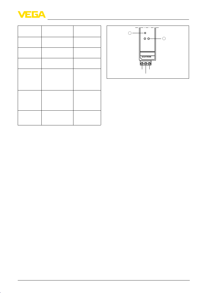
Abb. 6: Funktionsanzeige und HART-Buchsen
1 LED: Funktionsanzeige
2 HART-Kommunikationsbuchsen
7 Instandhalten und Störun-
7.1 Wartung
Bei bestimmungsgemäßer Verwendung ist
6 In Betrieb nehmen
im Normalbetrieb keine besondere Wartung
erforderlich.
6.1 Bedienung
Am VEGATRENN 149A Ex selbst gibt es
keinerlei Bedienelemente. Über die frontseitigen HART-Kommunikationsbuchsen kann
eine Parametrierung der angeschlossenen
HART-Sensoren ohne Unterbrechnung des
Messkreises vorgenommen werden. Der für
diesen Zweck benötigte Widerstand (250 Ω) ist
bereits im VEGATRENN 149A Ex integriert (nur
bei Anschluss von O+H). Die Bedienung erfolgt
über einen Windows-PC mit einer Parametrierungssoftware wie z. B. PACTware und entsprechendem DTM.
6.2 Funktionsanzeige
Die gelbe LED in der Frontplatte des VEGATRENN 149A Ex leuchtet, sobald ein Auswertsystem am Ausgang angeschlossen ist.
24816-01-131025
VEGATRENN 149A Ex • Ex-Speisetrenner für 4 … 20 mA/HART
7.2 Störungen beseitigen
Störungsursachen
Es wird ein Höchstmaß an Funktionssicherheit
gewährleistet. Dennoch können während des
Betriebes Störungen auftreten. Diese können
z. B. folgende Ursachen haben:
Messwert vom Sensor nicht korrekt
•
Spannungsversorgung
•
Störungen auf den Leitungen
•
Störungsbeseitigung
Die ersten Maßnahmen sind die Überprüfung
des Ein- und Ausgangssignals sowie der Spannungsversorgung. In vielen Fällen lassen sich
die Ursachen auf diesem Wege feststellen und
die Störungen so beseitigen.
24 Stunden Service-Hotline
Sollten diese Maßnahmen dennoch zu keinem
Ergebnis führen, rufen Sie in dringenden
Fällen die VEGA Service-Hotline an unter Tel.
+49 1805 858550.
Die Hotline steht Ihnen auch außerhalb der
üblichen Geschäftszeiten an 7 Tagen in der
Woche rund um die Uhr zur Verfügung. Da wir
diesen Service weltweit anbieten, erfolgt die
0+H
on
CONNECT
149A Ex
0-
0+
1
gen beseitigen
2
7
Page 8
8 Ausbauen
Unterstützung in englischer Sprache. Der Service ist kostenlos, es fallen lediglich die üblichen
Telefongebühren an.
7.3 Das Gerät reparieren
Sollte eine Reparatur erforderlich sein, gehen
Sie folgendermaßen vor:
Im Internet können Sie auf unserer Homepage
www.vega.com unter: "Downloads - Formulare
und Zertikate - Reparaturformular" ein Rücksendeformular (23 KB) herunterladen.
Sie helfen uns damit, die Reparatur schnell und
ohne Rückfragen durchzuführen.
Für jedes Gerät ein Formular ausdrucken
•
und ausfüllen
Das Gerät reinigen und bruchsicher verpa-
•
cken
Das ausgefüllte Formular und eventuell ein
•
Sicherheitsdatenblatt außen auf der Verpackung anbringen
Bitte erfragen Sie die Adresse für die Rück-
•
sendung bei Ihrer jeweiligen Vertretung. Ihre
zuständige Vertretung nden Sie auf unserer
Homepage www.vega.com unter: "Unter-
nehmen - VEGA weltweit"
8 Ausbauen
8.1 Ausbauschritte
Beachten Sie die Kapitel "Montieren" und "An
die Spannungsversorgung anschließen" und
führen Sie die dort angegebenen Schritte sinngemäß umgekehrt durch.
Eine fachgerechte Entsorgung vermeidet
negative Auswirkungen auf Mensch und Umwelt
und ermöglicht eine Wiederverwendung von
wertvollen Rohstoen.
Werkstoe: siehe Kapitel "Technische Daten"
Sollten Sie keine Möglichkeit haben, das Altgerät fachgerecht zu entsorgen, so sprechen Sie
mit uns über Rücknahme und Entsorgung.
8.2 Entsorgen
Das Gerät besteht aus Werkstoen, die von darauf spezialisierten Recyclingbetrieben wieder
verwertet werden können. Wir haben hierzu die
Elektronik leicht trennbar gestaltet und verwen-
den recyclebare Werkstoe.
WEEE-Richtlinie 2002/96/EG
Das vorliegende Gerät unterliegt nicht der
WEEE-Richtlinie 2002/96/EG und den entsprechenden nationalen Gesetzen. Führen Sie das
Gerät direkt einem spezialisierten Recyclingbetrieb zu und nutzen Sie dafür nicht die kommunalen Sammelstellen. Diese dürfen nur für privat
genutzte Produkte gemäß WEEE-Richtlinie
genutzt werden.
8
VEGATRENN 149A Ex • Ex-Speisetrenner für 4 … 20 mA/HART
24816-01-131025
Page 9
9 Anhang
9 Anhang
9.1 Technische Daten
Allgemeine Daten
Bauform Für Montage auf Tragschiene 35 x 7,5 nach DIN
Gewicht 150 g (0.33 lbs)
Gehäusewerksto Polycarbonat/ABS, UL94V-0
Anschlussklemmen
Ʋ Klemmenart Schraubklemme
Ʋ Max. Aderquerschnitt 1,5 mm² (AWG 16)
HART-Kommunikationsbuchsen an der Gerätefront (ø 2 mm)
Spannungsversorgung
Betriebsspannung 20 … 253 V AC/DC, 50/60 Hz
Max. Leistungsaufnahme 2,4 W
Vorgeschriebene Überstromschutzein-
richtung (im Bereich 20 … 253 V AC)
Sensorstromkreis
Anzahl Sensoren 1 x 4 … 20 mA/HART (5 x HART-Multidrop)
Eingangsart Aktiv (Sensorversorgung durch VEGATRENN 149A Ex)
Klemmenspannung 22,5 … 16,7 V bei 4 … 20 mA
Leerlaufspannung 26 V ±5 %
Kurzschlussstrom ≤ 32 mA
Innenwiderstand 328 Ω
EN 50022/60715
≤ 10 A
Auswertstromkreis
Anzahl 1 x 4 … 20 mA/HART
Ausgangsart Aktiv
Leerlaufspannung 24 V ±10 %
Max. Bürde (Lastwiderstand)
Ʋ Ohne Kommunikationswiderstand 0 … 700 Ω
Ʋ Mit Kommunikationswiderstand 0 … 450 Ω
Messabweichung
Referenzbedingungen Kalibriertemperatur 25 °C (77 °F)
Linearität ≤ 0,15 %
Einuss der Bürde ≤ 0,1 %
Einuss der Umgebungstemperatur
Ʋ Im Bereich 0 … +50 °C
(+32 … +122 °F)
Ʋ Im Bereich -20 … 0 °C (-4 … +32 °F) ≤ 0,2 %/10 K
24816-01-131025
VEGATRENN 149A Ex • Ex-Speisetrenner für 4 … 20 mA/HART
≤ 0,1 %/10 K
9
Page 10
9 Anhang
Anzeigen
Funktionsanzeige
Ʋ LED gelb leuchtet bei geschlossenem Ausgangsstromkreis
Ʋ LED Ansprechstrom < 2 mA
Umgebungsbedingungen
Umgebungstemperatur -20 … +50 °C (-4 … +122 °F)
Lager- und Transporttemperatur -20 … +70 °C (-4 … +158 °F)
Klimaklasse nach EN 60654-1, Klasse B2
Elektrische Schutzmaßnahmen
Schutzart IP 20
Überspannungskategorie II
Schutzklasse I
Elektrische Trennmaßnahmen
Sichere Trennung gemäß VDE 0106 Teil 1 zwischen allen Stromkreisen
Ʋ Bemessungsspannung 253 V
Ʋ Isolationsfestigkeit 3,75 kV
Funktionale Sicherheit (SIL)
Das Gerät kann in sicherheitsinstrumentierten Systemen entsprechend IEC 61508/IEC 61511-1
(Betriebsbewährtheit) eingesetzt werden.
Ist das Gerät mit SIL-Qualikation ab Werk bestellt, so ist das zugehörige Safety Manual mitgelie-
fert, dem detaillierte Informationen zum Thema "Funktionale Sicherheit (SIL)" entnommen werden
können.
Wird das Gerät ohne SIL-Qualikation ab Werk bestellt, so nden Sie das zugehörige Safety Manual unter "www.vega.com", "Downloads", "Zulassungen".
Zulassungen
Geräte mit Zulassungen können je nach Ausführung abweichende technische Daten haben.
Bei diesen Geräten sind deshalb die zugehörigen Zulassungsdokumente zu beachten. Diese sind
im Gerätelieferumfang enthalten oder können auf www.vega.com über "VEGA Tools" und "serial
number search" sowie über "Downloads" und "Zulassungen" heruntergeladen werden.
10
VEGATRENN 149A Ex • Ex-Speisetrenner für 4 … 20 mA/HART
24816-01-131025
Page 11

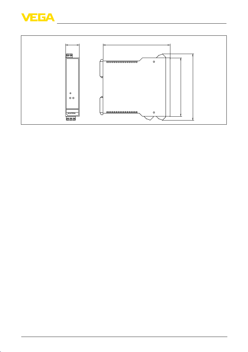
9.2 Maße
9 Anhang
22,5 mm
(0.89")
on
CONNECT
149AEx
Abb. 7: Maße VEGATRENN 149A Ex
112 mm (4.41")
96 mm (3.78")
110 mm (4.33")
24816-01-131025
VEGATRENN 149A Ex • Ex-Speisetrenner für 4 … 20 mA/HART
11
Page 12

Contents
Operating Instructions
Betriebsanleitung 2
DE
Operating Instructions 12
EN
Contents
1 About this document
1.1 Function ............................................13
1.2 Target group ......................................13
1.3 Symbolism used ................................13
2 For your safety
2.1 Authorised personnel ........................13
2.2 Appropriate use .................................13
2.3 Warning about incorrect use .............13
2.4 General safety instructions ................13
2.5 CE conformity ...................................14
2.6 Safety instructions for Ex areas .........14
2.7 Environmental instructions ................14
3 Product description
3.1 Conguration.....................................14
3.2 Principle of operation ........................14
3.3 Operation ..........................................14
3.4 Packaging, transport and storage......15
4 Mounting
4.1 Mounting instructions ........................15
5 Connecting to power supply
5.1 Preparing the connection ..................15
5.2 Connection procedure.......................15
5.3 Wiring plan ........................................16
6 Setup
6.1 Operation ..........................................17
6.2 Indication of the function ...................17
7 Maintenanceandfaultrectication
7.1 Maintenance .....................................17
7.2 Rectify faults......................................17
7.3 Instrument repair ...............................17
8 Dismounting
8.1 Dismounting steps ............................18
8.2 Disposal ............................................18
9 Supplement
9.1 Technical data ...................................19
9.2 Dimensions .......................................21
Mise en service 22
FR
Instrucciones de servicio 32
ES
24816-01-131025
12
Editing status: 2013-09-25
VEGATRENN 149A Ex • Ex-separator for 4 … 20 mA/HART
Page 13
2 For your safety
1 About this document
1.1 Function
This operating instructions manual provides
all the information you need for mounting,
connection and setup as well as important
instructions for maintenance and fault rectication. Please read this information before putting
the instrument into operation and keep this
manual accessible in the immediate vicinity of
the device.
1.2 Target group
This operating instructions manual is directed
to trained specialist personnel. The contents of
this manual should be made available to these
personnel and put into practice by them.
1.3 Symbolism used
Information, tip, note
This symbol indicates helpful additional
information.
Caution: If this warning is ignored, faults
or malfunctions can result.
Warning: If this warning is ignored,
injury to persons and/or serious damage
to the instrument can result.
Danger: If this warning is ignored, serious injury to persons and/or destruction
of the instrument can result.
Ex applications
This symbol indicates special instructions for Ex applications.
List
•
The dot set in front indicates a list with
no implied sequence.
Action
→
This arrow indicates a single action.
1 Sequence of actions
Numbers set in front indicate successive
steps in a procedure.
Battery disposal
This symbol indicates special information about the disposal of batteries and
accumulators.
24816-01-131025
VEGATRENN 149A Ex • Ex-separator for 4 … 20 mA/HART
2 For your safety
2.1 Authorised personnel
All operations described in this operating
instructions manual must be carried out only by
trained specialist personnel authorised by the
plant operator.
During work on and with the device the required
personal protective equipment must always be
worn.
2.2 Appropriate use
VEGATRENN 149A Ex is an [EEx ia] separator
with separate power supply for connection of
4 … 20 mA/HART sensors in two-wire version.
You can nd detailed information on the application range in chapter "Product description".
Operational reliability is ensured only if the instrument is properly used according to the speci-
cations in the operating instructions manual as
well as possible supplementary instructions.
For safety and warranty reasons, any invasive
work on the device beyond that described in the
operating instructions manual may be carried
out only by personnel authorised by the manu-
facturer. Arbitrary conversions or modications
are explicitly forbidden.
2.3 Warning about incorrect use
Inappropriate or incorrect use of the instrument
can give rise to application-specic hazards,
e.g. vessel overll or damage to system compo-
nents through incorrect mounting or adjustment.
2.4 General safety instructions
This is a state-of-the-art instrument complying
with all prevailing regulations and guidelines.
The instrument must only be operated in a
technically awless and reliable condition. The
operator is responsible for the trouble-free
operation of the instrument.
During the entire duration of use, the user is
obliged to determine the compliance of the
necessary occupational safety measures with
the current valid rules and regulations and also
take note of new regulations.
The safety instructions in this operating instructions manual, the national installation standards
13
Page 14

3 Product description
as well as the valid safety regulations and
accident prevention rules must be observed by
the user.
For safety and warranty reasons, any invasive
work on the device beyond that described in the
operating instructions manual may be carried
out only by personnel authorised by the manu-
facturer. Arbitrary conversions or modications
are explicitly forbidden.
The safety approval markings and safety tips on
the device must also be observed.
2.5 CE conformity
The device fullls the legal requirements of the
applicable EC guidelines. By axing the CE
marking, we conrm successful testing of the
product.
You can nd the CE Certicate of Conformity in
the download section of our homepage.
2.6 Safety instructions for Ex
areas
Please note the Ex-specic safety information
for installation and operation in Ex areas. These
safety instructions are part of the operating
instructions manual and come with the Exapproved instruments.
2.7 Environmental instructions
Protection of the environment is one of our most
important duties. That is why we have introduced an environment management system with
the goal of continuously improving company
environmental protection. The environment
management system is certied according to
DIN EN ISO 14001.
Please help us fulll this obligation by observing
the environmental instructions in this manual:
Chapter "Packaging, transport and storage"
•
Chapter "Disposal"
•
3 Product description
3.1 Conguration
Scope of delivery
The scope of delivery encompasses:
VEGATRENN 149A Ex separator
•
Documentation
•
– this operating instructions manual
– Ex-specic "Safety instructions" (depen-
ding on the version)
– if necessary, further certicates
Type plate
The nameplate contains the most important
data for identication and use of the instrument:
Article number
•
Serial number
•
Technical data
•
Article numbers, documentation
•
The order data and the documentation of the
instrument can be retrieved by means of the
instrument serial number on the type label. To
do this, go to www.vega.com, "VEGA Tools" and
"serial number search".
3.2 Principle of operation
Application area
VEGATRENN 149A Ex is an [EEx ia] separator
with separate power supply for connection of
4 … 20 mA/HART sensors in two-wire version.
As an associated electrical device, it ensures a
galvanic separation between sensor circuit and
processing circuit and thus between Ex and
non-Ex areas.
Functional principle
An integrated transmitter power supply powers
the connected sensor. The current signal from
the sensor (4 … 20 mA) is transferred linearly
and galvanically separated to the output. The
HART communication sockets in the front enable a bidirectional transmission of HART signals.
Voltage supply
Wide-range power supply unit with
20 … 253 V AC/DC for world-wide use.
Detailed information about the power supply
can be found in chapter "Technical data".
3.3 Operation
There are no adjustment elements on VEGATRENN 149A Ex. A parameter adjustment of the
connected sensors can be carried out via the
HART communication sockets. The adjustment of the connected sensors is carried out
preferrably via a Windows PC with a parameter
adjustment software such as PACTware and
24816-01-131025
14
VEGATRENN 149A Ex • Ex-separator for 4 … 20 mA/HART
Page 15

4 Mounting
respective DTM.
3.4 Packaging, transport and
storage
Packaging
Your instrument was protected by packaging
during transport. Its capacity to handle normal
loads during transport is assured by a test
based on ISO 4180.
The packaging of standard instruments consists
of environment-friendly, recyclable cardboard.
For special versions, PE foam or PE foil is also
used. Dispose of the packaging material via
specialised recycling companies.
Transport
Transport must be carried out in due consideration of the notes on the transport packaging.
Nonobservance of these instructions can cause
damage to the device.
Transport inspection
The delivery must be checked for completeness
and possible transit damage immediately at receipt. Ascertained transit damage or concealed
defects must be appropriately dealt with.
Storage
Up to the time of installation, the packages
must be left closed and stored according to the
orientation and storage markings on the outside.
Unless otherwise indicated, the packages must
be stored only under the following conditions:
Not in the open
•
Dry and dust free
•
Not exposed to corrosive media
•
Protected against solar radiation
•
Avoiding mechanical shock and vibration
•
Storage and transport temperature
Storage and transport temperature see
•
chapter "Supplement - Technical data Ambient conditions"
Relative humidity 20 … 85 %
•
4 Mounting
IP 20, the instrument is suitable for mounting in
switching cabinets.
VEGATRENN 149A Ex is a corresponding, intrinsically safe equipment and
must not be installed in hazardous areas.
A safe operation is only ensured if the
operating instructions and EG type approval certicate are observed. VEGATRENN 149A Ex must not be opened.
A distance of 50 mm to the intrinsically
safe terminals must be ensured when
mounting.
5 Connecting to power
supply
5.1 Preparing the connection
Note safety instructions
Always keep in mind the following safety instructions:
Connect only in the complete absence of
•
line voltage
If overvoltages or voltage peaks are
•
expected, overvoltage arresters should be
installed
Take note of safety instructions for Ex
applications
In hazardous areas you must take note
of the respective regulations, conformity
and type approval certicates of the
sensors and power supply units.
5.2 Connection procedure
Voltage supply
Make sure that the voltage corresponds to the
specications on the type label.
In the voltage range of 90 … 230 V AC, an easi-
ly accessible switch marked as cut-o switch as
well as an overload protection device (nominal
current ≤ 10 A) must be installed in the feed
circuit near the instrument.
L/+
N/-
4.1 Mounting instructions
VEGATRENN 149A Ex is constructed for carrier
rail mounting (top hat rail 35 x 7.5 according
to DIN EN 50022/60715). Through protection
24816-01-131025
VEGATRENN 149A Ex • Ex-separator for 4 … 20 mA/HART
Abb. 8: Connection voltage supply
L/+
N/-
15
Page 16

5 Connecting to power supply
Sensor circuit (Ex area)
The sensor must be connected to the blue
connection terminals I+ and I-. The sensor
circuit of the separator VEGATRENN 149A Ex is
separated from the processing circuit.
The sensor circuit is active, this means that the
connected sensor is powered by VEGATRENN
149A Ex.
-
+
I +I
I+
Abb. 9: Connection sensor circuit
1 Ex area
2 Non-Ex area
1
2
I-
Processing circuit (non-Ex area)
Processing systems such as e.g. an indicating
instrument or a PLC system are connected to
terminals O+/O-/O+H.
If a HART handheld or an interface adapter VEGACONNECT is connected to the communication sockets in the front, the processing system
must be connected to terminals O+H and O-.
The resistance necessary for HART communication is already integrated in VEGATRENN
149A Ex with this version. Keep in mind that
in this case the max. connectable load or load
resistance is reduced (see "Technical data" in
the "Supplement").
0 +0
0+H
0+
0-
Hart
VEGADIS 175
Abb. 10: Connection example with HART communication
OK
0 +0
0+H
0+ 0-
VEGADIS 175
OK
Abb. 11: Connection example without HART communication
5.3 Wiring plan
Terminal assignment
1
2
on
CONNECT
3 4
Abb. 12: Wiring plan VEGATRENN 149A Ex
1 Sensor circuit
2 HART communication socket
3 Processing circuit
4 Voltage supply
Designation Terminal assign-
ment
L/+ L (AC), + (DC) Voltage supply
N/- N (AC), - (DC) Voltage supply
Grounding Protective conduc-
O+
OO+H
tor PE
Measuring signal +
Measuring signal Measuring signal +
with HART resistor
I+
0+
Hart
+
–
+I
I
I–
0–
0+H
0+
0+
0–
L/+
Input and
output
Voltage supply
Measuring signal processing
circuit "Non-Ex
area"
L/+
N/–
N/–
24816-01-131025
16
VEGATRENN 149A Ex • Ex-separator for 4 … 20 mA/HART
Page 17

7 Maintenance and fault rectication
Designation Terminal assign-
ment
I+
I-
VEGACONNECT
Measuring signal
intrinsically safe +
Measuring signal
intrinsically safe -
HART communication sockets
Input and
output
Measuring signal sensor circuit
"Ex-area"
HART
handheld or VEGACONNECT
7 Maintenance and fault
7.1 Maintenance
If the instrument is used properly, no special
maintenance is required in normal operation.
7.2 Rectify faults
Failure reasons
6 Setup
A maximum of reliability is ensured. Nevertheless, faults can occur during operation. These
6.1 Operation
There are no adjustment elements on VEGATRENN 149A Ex. Via the HART communication
sockets in the front, a parameter adjustment of
the connected HART sensors can be carried
out without interrupting the measuring circuit.
The resistor (250 Ω) required for this purpose
is already integrated in VEGATRENN 149A
Ex (only in case of connection of O+H). The
adjustment is carried out via a Windows PC with
a parameter adjustment software such as e.g.
PACTware and respective DTM.
may be caused by the following, e.g.:
•
•
•
Faultrectication
The rst measure to be taken is to check the
input/output signal as well as the power supply.
In many cases, the causes can be determined
and faults can be quickly rectied.
24 hour service hotline
Should these measures not be successful,
please call in urgent cases the VEGA service
6.2 Indication of the function
The yellow LED in the front plate of VEGATRENN 149A Ex lights as soon as a signal conditioning instrument is connected to the output.
1
on
CONNECT
2
hotline under the phone no. +49 1805 858550.
The hotline is available to you 7 days a week
round-the-clock. Since we oer this service
world-wide, the support is only available in
the English language. The service is free of
charge, only the standard telephone costs will
be charged.
7.3 Instrument repair
If a repair is necessary, please proceed as
149A Ex
follows:
You can download a return form (23 KB) from
0+H
0-
0+
Abb. 13: Function indications and HART sockets
1 LED: indication of the function
2 HART communication sockets
our Internet homepage www.vega.com under:
"Downloads - Forms and certicates - Repair
form".
By doing this you help us carry out the repair
quickly and without having to call back for needed information.
•
•
•
24816-01-131025
VEGATRENN 149A Ex • Ex-separator for 4 … 20 mA/HART
rectication
Measured value from sensor not correct
Voltage supply
Interference on the cables
Print and ll out one form per instrument
Clean the instrument and pack it damageproof
Attach the completed form and, if need
be, also a safety data sheet outside on the
packaging
17
Page 18

8 Dismounting
Please ask the agency serving you for the
•
address of your return shipment. You can
nd the respective agency on our website
www.vega.com under: "Company - VEGA
worldwide".
8 Dismounting
8.1 Dismounting steps
Take note of chapters "Mounting" and "Connec-
ting to power supply" and carry out the listed
steps in reverse order.
8.2 Disposal
The instrument consists of materials which can
be recycled by specialised recycling companies.
We use recyclable materials and have designed
the parts to be easily separable.
WEEE directive 2002/96/EG
This instrument is not subject to the WEEE
directive 2002/96/EG and the respective national laws. Pass the instrument directly on to a
specialised recycling company and do not use
the municipal collecting points. These may be
used only for privately used products according
to the WEEE directive.
Correct disposal avoids negative eects on
humans and the environment and ensures
recycling of useful raw materials.
Materials: see chapter "Technical data"
If you have no way to dispose of the old instrument properly, please contact us concerning
return and disposal.
18
24816-01-131025
VEGATRENN 149A Ex • Ex-separator for 4 … 20 mA/HART
Page 19

9 Supplement
9 Supplement
9.1 Technical data
General data
Series For mounting on carrier rail 35 x 7.5 according to DIN
Weight 150 g (0.33 lbs)
Housing material Polycarbonate/ABS, UL94V-0
Connection terminals
Ʋ Type of terminal Screw terminal
Ʋ Max. wire cross-section 1.5 mm² (AWG 16)
HART communication sockets on the instrument front (ø 2 mm)
Voltage supply
Operating voltage 20 … 253 V AC/DC, 50/60 Hz
Max. power consumption 2.4 W
Specied overload protection (in the
range of 20 … 253 V AC)
Sensor circuit
Number of sensors 1 x 4 … 20 mA/HART (5 x HART-Multidrop)
Input type Active (sensor power supply by VEGATRENN 149A Ex)
Terminal voltage 22.5 … 16.7 V at 4 … 20 mA
O-load voltage 26 V ±5 %
Shortcircuit current ≤ 32 mA
Internal resistance 328 Ω
EN 50022/60715
≤ 10 A
Processing circuit
Quantity 1 x 4 … 20 mA/HART
Type of output active
O-load voltage 24 V ±10 %
Max. load (load resistance)
Ʋ without communication resistance 0 … 700 Ω
Ʋ with communication resistance 0 … 450 Ω
Deviation
Reference conditions Calibration temperature 25 °C (77 °F)
Linearity ≤ 0.15 %
Inuence of the load ≤ 0.1 %
Inuence of the ambient temperature
Ʋ in the range 0 … +50 °C
(+32 … +122 °F)
24816-01-131025
VEGATRENN 149A Ex • Ex-separator for 4 … 20 mA/HART
≤ 0.1 %/10 K
19
Page 20

9 Supplement
Ʋ in the range of -20 … 0 °C
≤ 0.2 %/10 K
(-4 … +32 °F)
Indications
Indication of the function
Ʋ LED yellow lights up with closed output circuit
Ʋ LED response current < 2 mA
Ambient conditions
Ambient temperature -20 … +50 °C (-4 … +122 °F)
Storage and transport temperature -20 … +70 °C (-4 … +158 °F)
Climatic class according to EN 60654-1, class B2
Electrical protective measures
Protection rating IP 20
Overvoltage category II
Protection class I
Electrical separating measures
Reliable separation according to VDE 0106 part 1 between all circuits
Ʋ Reference voltage 253 V
Ʋ Isolation resistance 3.75 kV
Functional safety (SIL)
The instrument can be used in safety-instrumented systems according to IEC 61508/IEC 61511-1
(service proven).
If the instrument is already ordered with SIL qualication Ex factory, then the corresponding Safety
Manual with information on the topic "Functional safety (SIL)" is part of the shipment.
If the instrument is ordered Ex factory without SIL qualication, then the corresponding Safety
Manual is available under "www.vega.com", "Downloads", "Approvals".
Approvals
Instruments with approvals can have dierent technical data depending on the version.
For that reason the associated approval documents of these instruments have to be carefully
noted. They are part of the delivery or can be downloaded under www.vega.com via "VEGA Tools"
and "serial number search" as well as via "Downloads" and "Approvals".
20
VEGATRENN 149A Ex • Ex-separator for 4 … 20 mA/HART
24816-01-131025
Page 21

9.2 Dimensions
9 Supplement
22,5 mm
(0.89")
on
CONNECT
149AEx
Abb. 14: Dimensions VEGATRENN 149A Ex
112 mm (4.41")
96 mm (3.78")
110 mm (4.33")
24816-01-131025
VEGATRENN 149A Ex • Ex-separator for 4 … 20 mA/HART
21
Page 22

Table des matières
Mise en service
Betriebsanleitung 2
DE
Operating Instructions 12
EN
Table des matières
Mise en service 22
FR
Instrucciones de servicio 32
ES
1 À propos de ce document
1.1 Fonctions ..........................................23
1.2 Personnes concernées .....................23
1.3 Symbolique utilisée ...........................23
2 Pour votre sécurité
2.1 Personnel autorisé ............................23
2.2 Utilisation appropriée ........................23
2.3 Avertissement contre les utilisations
incorrectes ........................................23
2.4 Consignes de sécurité générales ......24
2.5 Conformité CE ..................................24
2.6 Consignes de sécurité pour atmos-
phères Ex ..........................................24
2.7 Remarques relatives à l'environnement
24
3 Description du produit
3.1 Structure ...........................................24
3.2 Procédé de fonctionnement ..............24
3.3 Réglage et conguration ...................25
3.4 Emballage, transport et stockage ......25
4 Monter
4.1 Consignes de montage .....................25
5 Raccordement à l'alimentation en tensi-
on
5.1 Préparation du raccordement ............26
5.2 Étapes de raccordement ...................26
5.3 Schéma de raccordement .................27
6 Mettre en service
6.1 Réglage et conguration ...................27
6.2 Achage du fonctionnement.............27
7 Maintenance et élimination des défauts
7.1 Maintenance .....................................27
7.2 Éliminer les défauts ...........................27
7.3 Réparation de l'appareil ....................28
8 Démonter
8.1 Étapes de démontage .......................28
8.2 Recycler ............................................28
9 Annexe
9.1 Caractéristiques techniques ..............29
9.2 Dimensions .......................................31
24816-01-131025
22
Date de rédaction : 25/09/2013
VEGATRENN 149A Ex • Séparateur d'alimentation Ex pour 4 … 20 mA/HART
Page 23

2 Pour votre sécurité
1 À propos de ce document
1.1 Fonctions
La présente notice technique contient les
informations nécessaires vous permettant un
montage, un raccordement et une mise en service de l'appareil ainsi que des remarques importantes concernant l'entretien et l'élimination
des défauts. Il est donc important de la lire avant
d'eectuer la mise en service et de la conserver
près de l'appareil, accessible à tout moment
comme partie intégrante du produit.
1.2 Personnes concernées
Cette notice technique s'adresse à un per-
sonnel spécialisé et qualié. Ces spécialistes
doivent avoir connaissance de son contenu et le
mettre en pratique.
1.3 Symbolique utilisée
Information, conseil, remarque
Sous ce symbole, vous trouverez des informations complémentaires très utiles.
Prudence : Le non-respect de cette
recommandation peut entraîner des
pannes ou des défauts de fonctionnement.
Avertissement : Le non-respect de
cette instruction peut porter préjudice à
la personne manipulant l'appareil et/ou
peut entraîner de graves dommages à
l'appareil.
Danger : Le non-respect de cet avertissement peut entraîner des blessures
sérieuses à la personne manipulant
l'appareil et/ou peut détruire l'appareil.
Applications Ex
Vous trouverez à la suite de ce symbole
des remarques particulières concernant
les applications Ex.
Liste
•
Ce point précède une énumération
dont l'ordre chronologique n'est pas
obligatoire.
Étape de la procédure
→
Cette èche indique une étape de la
procédure.
1 Séquence d'actions
Les étapes de la procédure sont nu-
24816-01-131025
VEGATRENN 149A Ex • Séparateur d'alimentation Ex pour 4 … 20 mA/HART
mérotées dans leur ordre chronologique.
Élimination des piles
Vous trouverez à la suite de ce symbole
des remarques particulières concernant
l'élimination des piles et accumulateurs.
2 Pour votre sécurité
2.1 Personnel autorisé
Toutes les manipulations sur l'appareil indi-
quées dans cette notice ne doivent être eectuées que par du personnel qualié, spécialisé
et autorisé par l'exploitant de l'installation.
Porter toujours l'équipement de protection per-
sonnel nécessaire en travaillant avec l'appareil.
2.2 Utilisation appropriée
Le VEGATRENN 149A Ex est un séparateur
d'alimentation [EEx ia] avec alimentation de
tension séparée destiné au raccordement de
capteurs 4 … 20 mA/HART en version bilaire.
Vous trouverez des informations plus détaillées
concernant le domaine d'application au chapitre
" Description du produit ".
La sécurité de fonctionnement n'est assurée qu'à condition d'un usage conforme de
l'appareil en respectant les indications stipulées
dans le manuel de mise en service et dans les
éventuelles notices complémentaires.
Pour des raisons de sécurité et de garantie,
toute intervention sur l'appareil en dehors des
manipulations indiquées dans le manuel de
mise en service est strictement réservée à
des personnes autorisées par le fabricant de
l'appareil. Il est explicitement interdit de procéder de son propre chef à des transformations ou
modications sur l'appareil.
2.3 Avertissement contre les
utilisations incorrectes
Un usage non conforme ou non approprié de
l'appareil peut engendrer des risques spéci-
ques à l'application. Un montage incorrect ou
un réglage erroné peut entraîner par exemple
un débordement de cuve ou des dégâts dans
les composants de l'installation.
23
Page 24

3 Description du produit
2.4 Consignes de sécurité
générales
L'appareil respecte les règles de l'art et est conforme aux recommandations et des directives
habituelles. Il ne doit être utilisé que s'il est en
parfait état de fonctionnement. L'utilisateur est
responsable du fonctionnement sans incident
de l'appareil.
Pendant toute la durée d'exploitation de
l'appareil, l'exploitant doit en plus vérier que
les mesures nécessaires de sécurité du travail
concordent avec les normes actuelles en
vigueur et que les nouvelles réglementations y
sont incluses et respectées.
L'utilisateur doit respecter les consignes de
sécurité contenues dans ce mode d'emploi,
les standards d'installation spéciques au pays
et les règles de sécurité et les directives de
prévention des accidents en vigueur.
Pour des raisons de sécurité et de garantie,
toute intervention sur l'appareil en dehors des
manipulations indiquées dans le manuel de
mise en service est strictement réservée à
des personnes autorisées par le fabricant de
l'appareil. Il est explicitement interdit de procéder de son propre chef à des transformations ou
modications sur l'appareil.
Par ailleurs, il faudra tenir compte des consignes et des signalisations de sécurité apposées
sur l'appareil.
2.5 Conformité CE
L'appareil satisfait aux exigences légales des
directives respectives de la CE. Avec le marqua-
ge CE, nous conrmons que le contrôle a été
eectué avec succès.
Vous trouverez la déclaration de conformité CE
dans la zone de téléchargement sur notre site
web.
2.6 Consignes de sécurité pour
atmosphères Ex
Respectez les consignes de sécurité spéci-
ques pour les applications Ex. Celles-ci font
partie intégrale du manuel de mise en service et
sont jointes avec agrément Ex à la livraison de
chaque appareil Ex.
2.7 Remarques relatives à
l'environnement
La défense de notre environnement est une des
tâches les plus importantes et des plus prioritaires. C'est pourquoi nous avons mis en oeuvre
un système de management environnemental
ayant pour objectif l'amélioration continue de la
protection de l'environnement. Notre système
de management environnemental a été certié
selon la norme DIN EN ISO 14001.
Aidez-nous à satisfaire à ces exigences
et observez les remarques relatives à
l'environnement gurant dans ce manuel de
mise en service :
Au chapitre " Emballage, transport et
•
stockage "
Au chapitre " Recycler "
•
3 Description du produit
3.1 Structure
Compris à la livraison
La livraison comprend :
Séparateur d'alimentation VEGATRENN
•
149A Ex
Documentation
•
– Ce manuel de mise en service
– Les " Consignes de sécurité " spéciques
Ex (selon la version)
– Le cas échéant d'autres certicats
Plaque signalétique
La plaque signalétique contient les informations
les plus importantes servant à l'identication et
à l'utilisation de l'appareil :
Numéro d'article
•
Numéro de série
•
Caractéristiques techniques
•
Numéros d'articles documentation
•
Le numéro de série de l'appareil sur la plaque
signalétique vous permet d'interroger les
données de commande et la documentation de
l'appareil. Allez pour cela sur www.vega.com, "
VEGA Tools " et " serial number search ".
3.2 Procédé de fonctionnement
Domaine d'application
Le VEGATRENN 149A Ex est un séparateur
24816-01-131025
24
VEGATRENN 149A Ex • Séparateur d'alimentation Ex pour 4 … 20 mA/HART
Page 25

4 Monter
d'alimentation [EEx ia] avec alimentation en
énergie séparée, destiné au raccordement
des capteurs 4 … 20 mA/HART en version
bilaire. En tant que matériel électrique associé,
il assure une séparation galvanique entre le
circuit courant capteur et le circuit courant
d'exploitation et de ce fait entre la zone Ex et la
zone non Ex.
Principe de fonctionnement
Une alimentation intégrée alimente en énergie
le capteur raccordé. Le courant contraint par le
capteur (4 … 20 mA) est transmis à la sortie de
manière linéaire et avec séparation galvanique.
Les douilles de communication HART intégrées
en face avant permettent une transmission
bidirectionnelle des signaux HART.
Tension d'alimentation
Bloc d'alimentation à longue portée avec
20 … 253 V AC/DC pour une application dans
le monde entier.
Vous trouverez des données détaillées con-
cernant l'alimentation de tension au chapitre "
Caractéristiques techniques ".
3.3 Réglageetconguration
Le VEGATRENN 149A Ex ne possède lui
aucun élément de réglage. Un paramétrage des
capteurs raccordés peut se faire par les douilles
de communication HART. La conguration et
le réglage des capteurs raccordés s'eectue
de préférence par un PC Windows équipé d'un
logiciel de paramétrage comme PACTware et de
son DTM approprié.
3.4 Emballage, transport et
stockage
Emballage
Durant le transport jusqu'à son lieu
d'application, votre appareil a été protégé par
un emballage dont la résistance aux contraintes
de transport usuelles a fait l'objet d'un test selon
la norme DIN ISO 4180.
Pour les appareils standard, cet emballage
est en carton non polluant et recyclable. Pour
les versions spéciales, on utilise en plus de la
mousse ou des feuilles de polyéthylène. Faites
en sorte que cet emballage soit recyclé par une
entreprise spécialisée de récupération et de
recyclage.
24816-01-131025
VEGATRENN 149A Ex • Séparateur d'alimentation Ex pour 4 … 20 mA/HART
Transport
Le transport doit s'eectuer en tenant compte des indications faites sur l'emballage de
transport. Le non-respect peut entraîner des
dommages à l'appareil.
Inspection du transport
La livraison doit être vériée immédiatement
après réception quant à son intégralité et
à d'éventuels dommages dus au transport.
D'éventuels dommages de transport constatés
ou des vices cachés sont à traiter en conséquence.
Stockage
Les colis sont à conserver fermés jusqu'au
montage en veillant à respecter les marquages
de positionnement et de stockage apposés à
l'extérieur.
Sauf autre indication, entreposer les colis en
respectant les conditions suivantes :
Ne pas entreposer à l'extérieur
•
Entreposer dans un lieu sec et sans pous-
•
sière
Ne pas exposer à des produits agressifs
•
Protéger contre les rayons du soleil
•
Éviter des secousses mécaniques
•
Température de stockage et de transport
Température de transport et de stockage
•
voir au chapitre " Annexe - Caractéristiques
techniques - Conditions ambiantes "
Humidité relative de l'air 20 … 85 %
•
4 Monter
4.1 Consignes de montage
Le VEGATRENN 149A Ex est conçu pour un
montage sur rail porteur (rail oméga 35 x 7,5
selon DIN EN 50022/60715). Grâce à la protection IP 20, l'appareil est prévu pour un montage
dans des armoires de commande.
Le VEGATRENN 149A Ex est un
matériel associé de sécurité intrinsèque
et ne doit en aucun cas être installé en
atmosphères explosibles. Un fonctionnement sans risque est garanti uniquement
à condition de respecter les indications
stipulées dans le manuel de mise en
service et du certicat de contrôle de
type CE. Il est interdit d'ouvrir le VEGATRENN 149A Ex.
25
Page 26

5 Raccordement à l'alimentation en tension
Pour le montage, il faut respecter un
écart minimum de 50 mm entre les
circuits non S.I. et les circuits S.I.
5 Raccordement à
l'alimentation en tension
5.1 Préparation du raccordement
Respecter les consignes de sécurité
Respectez toujours les consignes de sécurité
suivantes :
Raccorder l'appareil uniquement hors
•
tension
Dans le cas où il faut s'attendre à des
•
surtensions ou à des pointes de tension,
installez des appareils de protection contre
les surtensions.
Respecter les consignes de sécurité pour
les applications Ex
En atmosphères explosibles, il faudra
respecter les réglementations respectives ainsi que les certicats de conformité et d'examen de type des capteurs et
appareils d'alimentation.
5.2 Étapes de raccordement
Tension d'alimentation
Assurez-vous que la tension correspond aux
indications gurant sur la plaque signalétique.
Dans la plage de tension comprise entre
90 … 253 V AC, il faudra installer près de
l'appareil dans le câble d'alimentation un
interrupteur facilement accessible et claire-
ment identié comme dispositif de coupure,
ainsi qu'un dispositif de protection envers
les surcharges de courant (courant nominal
≤ 10 A).
L/+
N/-
RENN 149A Ex est séparé du circuit courant
d'exploitation.
Le circuit courant capteur est actif signiant que
le capteur raccordé est alimenté en énergie par
le VEGATRENN 149A Ex.
-
+
I +I
I+
Abb. 16: Raccordement circuit courant capteur
1 Zone Ex
2 Zone non Ex
1
2
I-
Circuit courant d'exploitation (zone non Ex)
Des systèmes d'exploitation comme p.ex. un
indicateur de niveau ou un API seront raccordés
aux bornes O+/O-/O+H.
Si une console de programmation HART ou un
convertisseur d'interface VEGACONNECT est
raccordé aux douilles de communication en
face avant, le système d'exploitation devra être
raccordé aux bornes O+H et O-. La résistance
nécessaire à la communication HART est déjà
intégrée dans le VEGATRENN 149A Ex dans le
cas de cette variante de raccordement. Tenez
compte cependant que dans ce cas la charge
max. pouvant être raccordée et/ou la résistance
de charge diminuera (voir " Caractéristiques
techniques " en " Annexe ").
0 +0
0+H
0+
0-
Hart
VEGADIS 175
Abb. 17: Exemple de raccordement avec communication HART
OK
L/+
N/-
Abb. 15: Raccordement alimentation en tension
Circuit courant capteur (zone Ex)
Le capteur doit être raccordé aux bornes de
raccordement bleues I+ et I-. Le circuit courant
capteur du séparateur d'alimentation VEGAT-
26
VEGATRENN 149A Ex • Séparateur d'alimentation Ex pour 4 … 20 mA/HART
0 +0
0+H
0+ 0-
VEGADIS 175
Abb. 18: Exemple de raccordement sans communication HART
OK
24816-01-131025
Page 27

6 Mettre en service
5.3 Schéma de raccordement
Aectationdesbornes
1
+
–
+I
I
I+
I–
6 Mettre en service
6.1 Réglageetconguration
Le VEGATRENN 149A Ex ne possède luimême aucun élément de réglage . Vous pouvez
procéder à un paramétrage des capteurs HART
raccordés via les douilles de communication
HART en face avant de l'appareil et ce sans
interruption du circuit de mesure. La résistance
2
on
CONNECT
nécessaire à ce paramétrage (250 Ω) est déjà
intégrée au VEGATRENN 149A Ex (uniquement
au raccordement à O+H). Le réglage et la con-
guration s'eectuent via un PC Windows équipé
du logiciel de paramétrage PACTware™ et du
DTM approprié.
0–
0+H
L/+
0+
N/–
6.2 Achagedufonctionnement
0+
0+
0–
3 4
Hart
L/+
Abb. 19: Schéma de raccordement VEGATRENN 149A
Ex
1 Circuit courant capteur
2 Douille de communication HART
3 Circuit courant d'exploitation
4 Tension d'alimentation
Désignation Aectation des
bornes
Entrée et
sortie
L/+ L (AC), + (DC) Tension
d'alimentation
N/- N (AC), - (DC) Tension
d'alimentation
Mise à la terre Conducteur de pro-
tection PE
O+
OO+H
Signal de mesure +
Signal de mesure Signal de mesure
+ avec résistance
Tension
d'alimentation
Signal de mesure circuit courant
d'exploitation "
Zone non Ex "
HART
I+
I-
Signal de mesure en sécurité
intrinsèque +
Signal de me-
Signal de mesure circuit courant
capteur " Zone
Ex "
sure en sécurité
intrinsèque -
VEGACONNECT
Douilles de communication HART
Console de programmation
HART ou VEGACONNECT
24816-01-131025
VEGATRENN 149A Ex • Séparateur d'alimentation Ex pour 4 … 20 mA/HART
Le témoin jaune LED en face avant du VE-
N/–
GATRENN 149A Ex s'allumera aussitôt qu'un
système d'exploitation sera raccordé à la sortie.
1
Abb. 20: Achage du fonctionnement et douilles HART
1 LED : achage du fonctionnement
2 Douilles de communication HART
7 Maintenance et élimination
des défauts
7.1 Maintenance
Si l'on respecte les conditions d'utilisation,
aucun entretien particulier ne sera nécessaire
en fonctionnement normal.
7.2 Éliminer les défauts
Causes du défaut
Une très haute sécurité de fonctionnement est
garantie. Toutefois, des défauts peuvent apparaître pendant le fonctionnement de l'appareil.
0+H
on
CONNECT
149A Ex
0+
2
0-
27
Page 28

8 Démonter
Ces défauts peuvent par exemple avoir les
causes suivantes :
La valeur de mesure du capteur n'est pas
•
correcte
Tension d'alimentation
•
Perturbations sur les lignes
•
Élimination des défauts
Les premières mesures à prendre sont la
vérication du signal d'entrée/de sortie et de
l'alimentation de tension. Dans de nombreux
cas, ces mesures vous permettront de pouvoir
faire un constat des défauts et de les éliminer.
Service d'assistance technique 24h/24
Si toutefois ces mesures n'aboutissent à
aucun résultat, vous avez la possibilité - en cas
d'urgence - d'appeler le service d'assistance
technique VEGA, numéro de téléphone de la
hotline +49 1805 858550.
Ce service d'assistance technique est à votre
disposition également en dehors des heures
de travail, à savoir 7 jours sur 7 et 24h/24. Étant
proposé dans le monde entier, ce service est en
anglais. Il est gratuit, vous n'aurez à payer que
les frais de communication.
7.3 Réparation de l'appareil
Si une réparation venait à s'imposer, contactez
au préalable votre interlocuteur local :
Sur internet, vous avez la possibilité de télécharger sur notre page d'accueil www.vega.com
sous : " Téléchargements - Formulaires et certi-
cats - Formulaire de réparation " un formulaire
de renvoi (23 Ko).
Vos informations précises nous aideront à accélérer les délais de réparation.
Prière d'imprimer et de remplir un formulaire
•
par appareil
Prière de nettoyer et d'emballer l'appareil
•
soigneusement de façon à ce qu'il ne puisse
être endommagé
Prière de joindre le formulaire dûment rempli
•
et éventuellement une che de sécurité, le
tout apposé sur l'emballage de l'appareil.
Veuillez demander l'adresse de renvoi pour
•
les réparations auprès de votre agence respective. Vous trouverez celle-ci sur notre site
internet www.vega.com sous la rubrique : "
Société - VEGA dans le monde ".
8 Démonter
8.1 Étapes de démontage
Suivez les indications des chapitres " Montage "
et " Raccordement à l'alimentation en tension "
et procédez de la même manière mais en sens
inverse.
8.2 Recycler
L'appareil se compose de matériaux recyclab-
les par des entreprises spécialisées. À cet eet,
l'électronique a été conçue facilement détachable et les matériaux utilisés sont recyclables.
Directive DEEE 2002/96/CE
Le présent appareil n'est pas soumis à la directive DEEE 2002/96/CE et aux lois nationales
respectives. Apportez l'appareil directement
à une entreprise de recyclage spécialisée et
n'utilisez pas les points de récupération communaux. Ceux-ci sont destinés uniquement à
des produits à usage privé conformément à la
réglementation DEEE.
Une récupération professionnelle évite les
eets négatifs pouvant agir sur l'homme et son
environnement tout en préservant la valeur des
matières premières par un recyclage adéquat.
Matériaux : voir au chapitre " Caractéristiques
techniques "
Au cas où vous n'auriez pas la possibilité de
faire recycler le vieil appareil par une entreprise spécialisée, contactez-nous. Nous vous
conseillerons sur les possibilités de reprise et
de recyclage.
24816-01-131025
28
VEGATRENN 149A Ex • Séparateur d'alimentation Ex pour 4 … 20 mA/HART
Page 29

9 Annexe
9 Annexe
9.1 Caractéristiques techniques
Données générales
Construction Pour montage sur rail porteur 35 x 7,5 selon DIN
Poids 150 g (0.33 lbs)
Matériau du boîtier polycarbonate/ABS, UL94V-0
Bornes de raccordement
Ʋ Type de bornes Borne à vis
Ʋ Section des conducteurs max. 1,5 mm² (AWG 16)
Douilles de communication HART en face avant de l'appareil (ø 2 mm)
Tension d'alimentation
Tension de service 20 … 253 V AC/DC, 50/60 Hz
Consommation max. 2,4 W
Dispositif de protection contre les
surcharges de courant imposé (dans la
plage 20 … 253 V AC)
Circuit courant capteur
Nombre de capteurs 1 x 4 … 20 mA/HART (5 x HART-Multidrop)
Type d'entrée Actif (alimentation du capteur par le VEGATRENN 149A
Tension aux bornes 22,5 … 16,7 V à 4 … 20 mA
Tension en circuit ouvert 26 V ±5 %
Courant de court-circuit ≤ 32 mA
Résistance interne 328 Ω
EN 50022/60715
≤ 10 A
Ex)
Circuit courant d'exploitation
Nombre 1 x 4 … 20 mA/HART
Type de sortie Actif
Tension en circuit ouvert 24 V ±10 %
Charge max. (résistance de charge)
Ʋ sans résistance de communication 0 … 700 Ω
Ʋ avec résistance de communication 0 … 450 Ω
Erreur de mesure
Conditions de référence Température de calibrage 25 °C (77 °F)
Linéarité ≤ 0,15 %
Inuence de la charge ≤ 0,1 %
Inuence de la température ambiante
Ʋ dans la plage 0 … +50 °C
(+32 … +122 °F)
24816-01-131025
VEGATRENN 149A Ex • Séparateur d'alimentation Ex pour 4 … 20 mA/HART
≤ 0,1 %/10 K
29
Page 30

9 Annexe
Ʋ dans la plage -20 … 0 °C
≤ 0,2 %/10 K
(-4 … +32 °F)
Achages
Achage du fonctionnement
Ʋ LED jaune est allumé lorsque le circuit courant de sortie est fermé
Ʋ LED courant de déclenchement < 2 mA
Conditions ambiantes
Température ambiante -20 … +50 °C (-4 … +122 °F)
Température de stockage et de transport -20 … +70 °C (-4 … +158 °F)
Classe climatique selon EN 60654-1, classe B2
Mesures de protection électrique
Type de protection IP 20
Catégorie de surtensions II
Classe de protection I
Mesures d'isolement électrique
Séparation sûre selon VDE 0106 partie 1 entre tous les circuits courant
Ʋ Tension assignée 253 V
Ʋ Résistance d'isolement 3,75 kV
Sécurité fonctionnelle (SIL)
L'appareil peut être utilisé dans des systèmes de sécurité instrumentés suivant la norme
IEC 61508/IEC 61511-1 (validité en utilisation).
Pour les appareils possédant une qualication SIL réglée en usine, le Safety Manual correspon-
dant est compris à la livraison vous donnant des informations détaillées sur la " Sécurité fonctionnelle (SIL) ".
Pour les appareils ne possédant pas de qualication SIL réglée en usine, vous trouverez le Safety
Manual correspondant sous " www.vega.com ", " Téléchargements ", " Agréments ".
Agréments
Les appareils avec agréments peuvent avoir des caractéristiques techniques diérentes selon la
version.
Pour ces appareils, il faudra donc respecter les documents d'agréments respectifs. Ceux-ci font
partie de la livraison des appareils ou peuvent être téléchargés sur www.vega.com via " VEGA
Tools " et " serial number search " ainsi que via " Téléchargements " et " Agréments ".
30
VEGATRENN 149A Ex • Séparateur d'alimentation Ex pour 4 … 20 mA/HART
24816-01-131025
Page 31
9.2 Dimensions
9 Annexe
22,5 mm
(0.89")
on
CONNECT
149AEx
Abb. 21: Encombrement VEGATRENN 149A Ex
112 mm (4.41")
96 mm (3.78")
110 mm (4.33")
24816-01-131025
VEGATRENN 149A Ex • Séparateur d'alimentation Ex pour 4 … 20 mA/HART
31
Page 32

Índice
Instrucciones de servicio
Betriebsanleitung 2
DE
Operating Instructions 12
EN
Índice
Mise en service 22
FR
Instrucciones de servicio 32
ES
1 Acerca de este documento
1.1 Función .............................................33
1.2 Grupo destinatario ............................33
1.3 Simbología empleada .......................33
2 Para su seguridad
2.1 Personal autorizado ..........................33
2.2 Empleo acorde con las prescripciones .
33
2.3 Aviso contra uso incorrecto ...............33
2.4 Instrucciones generales de seguridad ..
33
2.5 Conformidad CE ...............................34
2.6 Instrucciones de seguridad para zonas
Ex ......................................................34
2.7 Instrucciones acerca del medio ambi-
ente ...................................................34
3 Descripción del producto
3.1 Construcción .....................................34
3.2 Principio de operación ......................34
3.3 Conguración ....................................35
3.4 Embalaje, transporte y almacenaje ...35
4 Montar
4.1 instrucciones de montaje ..................35
5 Conectar a la alimentación de tensión
5.1 Preparación de la conexión ...............35
5.2 Pasos de conexión ............................36
5.3 Esquema de conexión .......................37
6 Puesta en marcha
6.1 Conguración ....................................37
6.2 Indicación de funcionamiento ...........37
7 Mantenimiento y eliminación de fallos
7.1 Mantenimiento ..................................37
7.2 Eliminar fallos ....................................38
7.3 Reparación del equipo ......................38
8 Desmontaje
8.1 Secuencia de desmontaje .................38
8.2 Eliminar .............................................38
9 Anexo
9.1 Datos técnicos ..................................39
9.2 Medidas ............................................41
24816-01-131025
32
Estado de redacción: 2013-09-25
VEGATRENN 149A Ex • Ex-separador para 4 … 20 mA/HART
Page 33

2 Para su seguridad
1 Acerca de este documento
1.1 Función
Este manual de instrucciones suministra las
informaciones necesarias para el montaje,
la conexión y puesta en servicio, así como
instrucciones importantes de mantenimiento y
eliminación de fallos Por eso léala antes de la
puesta en servicio y consérvela todo el tiempo
al alcance de la mano en las cercanías del equipo como parte integrante del producto.
1.2 Grupo destinatario
El presente manual de instrucciones está
dirigido a los especialistas capacitados. Hay
que facilitar el acceso de los especialistas al
contenido del presente manual de instrucciones
y aplicarlo.
1.3 Simbología empleada
Información, sugerencia, nota
Este símbolo caracteriza informaciones
adicionales de utilidad.
Cuidado: En caso de omisión de ese
aviso se pueden producir fallos o interrupciones.
Aviso: En caso de omisión de ese aviso
se pueden producir lesiones personales
y/o daños graves del equipo.
Peligro: En caso de omisión de ese
aviso se pueden producir lesiones
personales graves y/o la destrucción del
equipo.
Aplicaciones Ex
Este símbolo caracteriza instrucciones
especiales para aplicaciones Ex.
Lista
•
El punto precedente caracteriza una lista
sin secuencia obligatoria
Paso de procedimiento
→
Esa echa caracteriza un paso de operación individual.
1 Secuencia de procedimiento
Los números precedentes caracterizan
pasos de operación secuenciales.
Eliminación de baterías
Este símbolo caracteriza indicaciones
especiales para la eliminación de baterías y acumuladores.
24816-01-131025
VEGATRENN 149A Ex • Ex-separador para 4 … 20 mA/HART
2 Para su seguridad
2.1 Personal autorizado
Todas las operaciones descritas en este
manual de instrucciones pueden ser realizadas
solamente por especialistas capacitados, autorizados por el operador del equipo.
Durante los trabajos en y con el equipo siempre
es necesario el uso del equipo de protección
necesario.
2.2 Empleo acorde con las
El VEGATRENN 149A Ex es un seccionador
de alimentación [EEx ia] con alimentación de
energía individual para la conexión de sensores
4 … 20 mA/HART en versión de dos hilos.
Informaciones detalladas sobre el campo de
aplicación se encuentran en el capítulo "Descripción del producto".
La conabilidad funcional del equipo está
garantizada solo en caso de empleo acorde con
las prescripciones según las especicaciones
en el manual de instrucciones del equipo así
como las instrucciones suplementarias.
Por motivos de seguridad y de garantía las
manipulaciones en el equipo que excedan
las operaciones necesarias descritas en el
manual de instrucciones deben ser realizadas
exclusivamente por el personal autorizado del
fabricante
2.3 Aviso contra uso incorrecto
En caso de empleo inadecuado o contrario a
las prescripciones se pueden producir riesgos
de aplicación especícos de este equipo, por
ejemplo, un sobrellenado de depósito o daños
en las partes del equipo a causa de montaje o
ajuste erróneo.
2.4 Instrucciones generales de
El equipo corresponde con el estado tecnológico bajo observación de las prescripciones y
recomendaciones normales. Solamente puede
emplearse en estado técnico perfecto y con seguridad funcional. El operador es responsable
por el funcionamiento del equipo sin fallos.
prescripciones
seguridad
33
Page 34

3 Descripción del producto
Además, el operador está en la obligación de
determinar durante el tiempo completo de empleo la conformidad de las medidas de seguridad
del trabajo necesarias con el estado actual de
las regulaciones validas en cada caso y las
nuevas prescripciones.
El usuario tiene que respetar las instrucciones
de seguridad de este manual de instrucciones,
las normas de instalación especícas del país y
las normas validas de seguridad y de prevención de accidentes.
Por motivos de seguridad y de garantía las
manipulaciones en el equipo que excedan
las operaciones necesarias descritas en el
manual de instrucciones deben ser realizadas
exclusivamente por el personal autorizado del
fabricante
Además, hay que atender a los símbolos e indicaciones de seguridad puestos en el equipo.
2.5 Conformidad CE
El equipo cumple los requisitos legales de la
norma CE correspondiente. Con el símbolo CE
certicamos la comprobación exitosa
La declaración de conformidad CE está en la
zona de descarga de nuestro sitio web.
2.6 Instrucciones de seguridad
para zonas Ex
En caso de aplicaciones Ex tener en cuenta
las instrucciones de seguridad especícas
Ex.Estas forman parte del manual de instrucciones y están anexas a cada equipo con
homologación Ex.
2.7 Instrucciones acerca del
medio ambiente
La protección de la base natural de vida es una
de las tareas más urgentes. Por eso hemos introducido un sistema de gestión del medio ambiente, con el objetivo de mejorar continuamente
el medio ambiente empresarial. El sistema de
gestión del medio ambiente está certicado por
la norma DIN EN ISO 14001.
Ayúdenos a satisfacer esos requisitos, pres-
tando atención a las instrucciones del medio
ambiente en este manual:
Capitulo "Embalaje, transporte y alma-
•
cenaje"
Capitulo "Reciclaje"
•
3 Descripción del producto
3.1 Construcción
Alcance de suministros
El alcance de suministros comprende:
Seccionador de alimentación VEGATRENN
•
149A Ex
Documentación
•
– Este manual de instrucciones
– "Instrucciones de seguridad" especicas
EX (en dependencia de la versión)
– Otras certicaciones en caso necesario
Placa de tipos
La placa de tipos contiene los datos más
importantes para la identicación y empleo del
equipo.
Número de artículo
•
Número de serie
•
Datos técnicos
•
Números de artículo documentación
•
El número de serie en la placa de tipos le
permite llamar los datos del pedido de pedido
y la documentación del equipo. Para ello ir a
www.vega.com, "VEGA Tools" y "serial number
search".
3.2 Principio de operación
Campo de aplicación
El VEGATRENN 149A Ex es un seccionador
de alimentación [EEx ia] con alimentación de
energía individual para la conexión de sensores
4 … 20 mA/HART en versión de dos hilos.
Como medio de producción eléctrico correspondiente el mismo asegura una separación
galvánica entre los circuitos de corriente del
sensor y de análisis y de esta forma entre Ex y
no Ex.
Principio de funcionamiento
Una alimentación de convertidor de medición
incorporada alimenta de energía al sensor
conectado. La corriente característica del sensor (4 … 20 mA) se transmite a la salida separada lineal y galvánicamente. Los terminales de
comunicación HART incorporados posibilitan la
transmisión bidireccional de señales HART.
24816-01-131025
34
VEGATRENN 149A Ex • Ex-separador para 4 … 20 mA/HART
Page 35

4 Montar
Alimentación de tensión
Fuente de alimentación de alta capacidad
20 … 253 V AC/DC para uso internacional.
Informaciones detalladas para la alimentación
de tensión están en el capítulo Datos técnicos.
3.3 Conguración
En el VEGATRENN 149A Ex propio no hay
ningún elemento de manejo. A través de los
terminales de comunicación HART se puede
realizar un ajuste de parámetros de los sensores conectados El manejo de los sensores
conectados se realiza preferentemente a través
de un PC-Windows con software de ajuste de
parámetros PACTware y DTM correspondiente.
condiciones, siempre y cuando no se indique
otra cosa:
No mantener a la intemperie
•
Almacenar seco y libre de polvo
•
No exponer a ningún medio agresivo
•
Proteger de los rayos solares
•
Evitar vibraciones mecánicas
•
Temperatura de almacenaje y transporte
Temperatura de almacenaje y transporte
•
ver "Anexo - Datos técnicos - Condiciones
ambientales"
Humedad relativa del aire 20 … 85 %
•
4 Montar
4.1 instrucciones de montaje
3.4 Embalaje, transporte y
almacenaje
Embalaje
Su equipo está protegido por un embalaje
durante el transporte hasta el lugar de empleo.
Aquí las solicitaciones normales a causa del
transporte están aseguradas mediante un control basándose en la norma DIN EN 24180.
En caso de equipos estándar el embalaje es
de cartón, compatible con el medio ambiente y
reciclable. En el caso de versiones especiales
se emplea adicionalmente espuma o película
de PE. Deseche los desperdicios de material de
embalaje a través de empresas especializadas
en reciclaje.
Transporte
Hay que realizar el transporte, considerando las
instrucciones en el embalaje de transporte. La
falta de atención puede tener como consecuencia daños en el equipo.
Inspección de transporte
Durante la recepción hay que comprobar
inmediatamente la integridad del alcance de
suministros y daños de transporte eventuales.
Hay que tratar correspondientemente los daños
de transporte o los vicios ocultos determinados.
Almacenaje
Hay que mantener los paquetes cerrados hasta
el montaje, y almacenados de acuerdo de las
marcas de colocación y almacenaje puestas en
el exterior.
Almacenar los paquetes solamente bajo esas
24816-01-131025
VEGATRENN 149A Ex • Ex-separador para 4 … 20 mA/HART
El VEGATRENN 149A Ex está construido
para montaje en regletas de montaje (Riel
de perl de sombrero 35 x 7,5 según DIN
EN 50022/60715). Por el tipo de protección
IP 20 el instrumento está previsto para el montaje en armarios de conexiones.
5 Conectar a la alimentación
5.1 Preparación de la conexión
Prestar atención a las indicaciones de
seguridad
Prestar atención fundamentalmente a las instrucciones de seguridad siguientes:
Conectar solamente en estado libre de
•
tensión
En caso de esperarse sobrecargas o picos
•
de voltaje, hay que montar un aparato de
protección contra sobrecarga
VEGATRENN 149A Ex en versión Ex es
un medio de producción suplementario
con seguridad intrínseca y no puede
instalarse en áreas con riesgo de explosión. Un funcionamiento sin peligros se
garantiza solamente respetando la ins-
trucción de servicio y de la certicación
de control de tipos CE. El VEGATRENN
149A Ex no se puede abrir.
Durante el montaje hay que garantizar
una distancia de 50 mm (Medida del
hilo) hacia los terminales con seguridad
intrínseca.
de tensión
35
Page 36

5 Conectar a la alimentación de tensión
Atender las instrucciones de seguridad
para aplicaciones Ex
En áreas con peligro de explosión hay
que atender las prescripciones, los cer-
ticados de conformidad y de control de
tipos correspondientes de los sensores
y equipos de alimentación.
5.2 Pasos de conexión
Alimentación de tensión
Asegurar, que la tensión coincida con las espe-
cicaciones de la placa de tipos.
En el rango de tensión de 90 … 253 V AC tiene
que haber puesto un interruptor de fácil acceso
marcado como disyuntor en la línea en las cercanías del instrumento, así como un dispositivo
de protección contra sobrecorriente (Corriente
nominal ≤ 10 A).
L/+
N/-
L/+
N/-
Abb. 22: Conexión alimentación de tensión
Circuito del sensor (Zona Ex)
Hay que conectar el sensor a los bornes de
conexión azules I+ y I-. El circuito de corriente
del sensor del seccionador de alimentación VEGATRENN 149A Ex está separado del circuito
de corriente de análisis.
El circuito del sensor está activo, esto signica
que el sensor conectado es alimentado de
energía desde el VEGATRENN 149A Ex.
adaptador de interfaces VEGACONNECT, hay
que conectar el sistema de análisis a los bornes
O+H y O-. La resistencia necesaria para la comunicación HART está previamente integrada
VEGATRENN 149A Ex para esa variante de
conexión. Tener en cuenta, que en este caso
se reduce la carga o las resistencia de carga
máxima conectables (ver "Datos técnicos" en
el "Anexo").
0 +0
0+H
0+
0-
Hart
VEGADIS 175
Abb. 24: Ejemplo de conexión con comunicación
HART
0+H
0+ 0-
VEGADIS 175
Abb. 25: Ejemplo de conexión sin comunicación HART
OK
0 +0
OK
-
+
I +I
I+
1
2
I-
Abb. 23: Conexión circuito del sensor
1 Zona Ex
2 Zona no Ex
Circuito del analizador (Zona no Ex)
En los bornes O+/O-/O+H se conectan sistemas de análisis, p.ej. un instrumento indicador o
un sistema PLC.
Si se conecta un comunicador HART o un
36
VEGATRENN 149A Ex • Ex-separador para 4 … 20 mA/HART
24816-01-131025
Page 37

7 Mantenimiento y eliminación de fallos
5.3 Esquema de conexión
Ocupación de terminales
1
2
on
CONNECT
3 4
Abb. 26: Esquema de conexión VEGATRENN 149A Ex
1 Circuito de corriente del sensor
2 Terminal de comunicación HART
3 Circuito de corriente de análisis
4 Alimentación de tensión
Denominación
Ocupación de
terminales
L/+ L (AC), + (DC) Alimentación de
N/- N (AC), - (DC) Alimentación de
Puesta a
tierra
O+
OO+H
Conductor de puesta a tierra PE
Señal de medición +
Señal de medición
Señal de medición
+ con resistencia
HART
I+
I-
Señal de medición seguridad
intrínseca +
Señal de medición seguridad
intrínseca -
VEGACONNECT
Terminales de comunicación HART
+
+I
I
I+
0+
Hart
–
I–
0–
0+H
0+
L/+
0+
0–
L/+
Entrada y
salida
tensión
tensión
Alimentación de
tensión
Señal de medi-
ción (Circuito del
analizador) "Zona no Ex"
Señal de medi-
ción (Circuito del
analizador) "Zona Ex"
Comunicador
HART o VEGACONNECT
N/–
N/–
6 Puesta en marcha
6.1 Conguración
En el VEGATRENN 149A Ex propio no hay
ningún elemento de manejo. A través de los
terminales frontales de comunicación HART
se puede realizar un ajuste de parámetros de
los sensores conectados sin interrupción del
circuito de medición. La resistencia necesaria
con ese objetivo (250 Ω) se encuentra integrada previamente en el VEGATRENN 149A Ex
(solo para la conexión de O+H). El manejo de
los sensores conectados se realiza a través de
un PC-Windows con un software de ajuste de
parámetros PACTware y DTM correspondiente.
6.2 Indicación de
funcionamiento
El LED amarillo en la placa frontal del VEGATRENN 149A Ex se enciende, inmediatamente
que se conecta un sistema de análisis en la
salida.
0+H
on
CONNECT
149A Ex
0+
2
0-
1
Abb. 27: Indicación de funcionamiento y enchufes
HART
1 LED: Indicación de funcionamiento
2 Terminales de comunicación HART
7 Mantenimiento y eliminaci-
ón de fallos
7.1 Mantenimiento
En caso de empleo acorde con las prescripciones no se requiere mantenimiento especial
alguno durante el régimen normal de funcionamiento.
24816-01-131025
VEGATRENN 149A Ex • Ex-separador para 4 … 20 mA/HART
37
Page 38

8 Desmontaje
7.2 Eliminar fallos
Causas de fallo
Se garantiza una medida elevada de seguridad
de funcionamiento. Sin embargo durante el
funcionamiento pueden aparecer fallos. Esos
fallos pueden tener por ejemplo las causas
siguientes:
Valor de medición del sensor incorrecto
•
Alimentación de tensión
•
Fallos en los cables
•
Eliminación de fallo
Las primeras medidas son la comprobación de
la señal de entrada/salida así como la alimentación de tensión. En muchos casos por estas
vías pueden determinarse las causas y eliminar
así las interrupciones.
Línea directa de asistencia técnica - Servicio 24 horas
Si estas medidas no producen ningún resultado, llamar la línea directa de servicio VEGA en
casos urgentes al Tel. +49 1805 858550.
La línea directa esta disponible durante las 24
horas incluso fuera de los horarios normales de
trabajo 7 días a la semana. El soporte se realiza
en idioma inglés porque el servicio se ofrece a
escala mundial. El servicio es gratuito, solamente se carga la tarifa telefónica local.
7.3 Reparación del equipo
Si es necesaria una reparación, proceder de la
forma siguiente:
En Internet puede descargarse de nuestra
página principal www.vega.com en: "Descargas
- Formularios y Certicados - Formulario de reparación" un formulario de devolución (23 KB).
De esta forma nos ayudan a realizar la reparación de forma rápida y sin necesidad de
aclaraciones.
Llenar y enviar un formulario para cada
•
equipo
Limpiar el equipo, empacándolo a prueba
•
de rotura
Colocar el formulario lleno y una hoja de
•
datos de seguridad eventualmente en la
parte externa del equipo
Favor de averiguar la dirección para la
•
devolución a su representación correspondiente. Usted puede encontrar la representación correspondiente en nuestra página
principal www.vega.com en: "Empresas
- VEGA internacional"
8 Desmontaje
8.1 Secuencia de desmontaje
Atender los capítulos "Montaje" y "Conexión a
la alimentación de tensión" siguiendo los pasos
descritos allí análogamente en secuencia
inversa.
8.2 Eliminar
El equipo se compone de materiales recuperables por establecimiento especializados de reciclaje. Para ello, hemos diseñado la electrónica
de fácil desconexión, empleando materiales
recuperables.
Directiva WEEE 2002/96/CE
Este equipo no responde a la directiva WEEE
2002/96/CE y las leyes nacionales correspondientes. Llevar el equipo directamente a una
empresa especializada de reciclaje, sin emplear
para esto los puntos comunales de recogida.
Los mismos pueden emplearse solamente para
productos de uso privado según la directiva
WEEE.
Un reciclaje especializado evita consecuencias
negativas sobre el hombre y el medio ambiente, posibilitando la recuperación de materias
primas valiosas.
Materiales: ver "Datos técnicos"
Si no tiene posibilidades, de reciclar el equipo
viejo de forma especializada, consulte con nosotros acerca de las posibilidades de reciclaje
o devolución.
24816-01-131025
38
VEGATRENN 149A Ex • Ex-separador para 4 … 20 mA/HART
Page 39

9 Anexo
9 Anexo
9.1 Datos técnicos
Datos generales
Forma constructiva Para el montaje en regleta de montaje 35 x 7,5 según
Peso 150 g (0.33 lbs)
Material de la carcasa Policarbonato/ABS, UL94V-0
Terminales de conexión
Ʋ Tipo de terminal Terminal con tornillo
Ʋ Sección máx.de conductor 1,5 mm² (AWG 16)
Terminales de comunicación HART en la parte frontal del instrumento (ø 2 mm)
Alimentación de tensión
Tensión de trabajo 20 … 253 V AC/DC, 50/60 Hz
Consumo de energía máx 2,4 W
Dispositivo de protección contra sob-
recorriente especicado (en el rango
20 … 253 V AC)
Circuito de corriente del sensor
Cantidad de sensores 1 x 4 … 20 mA/HART (5 x HART-Multidrop)
Tipo de entrada Activo (Alimentación del sensor a través de VEGAT-
Tensión en los terminales 22,5 … 16,7 V para 4 … 20 mA
Tensión en vacío 26 V ±5 %
Corriente de cortocircuito ≤ 32 mA
Resistencia interna 328 Ω
DIN EN 50022/60715
≤ 10 A
RENN 149A Ex)
Circuito de corriente de análisis
Cantidad 1 x 4 … 20 mA/HART
Tipo de salida Activa
Tensión en vacío 24 V ±10 %
Carga máx. (Resistencia de carga)
Ʋ sin resistencia de comunicación 0 … 700 Ω
Ʋ con resistencia de comunicación 0 … 450 Ω
Error de medición
Condiciones de referencia Temperatura de calibración 25 °C (77 °F)
Linealidad ≤ 0,15 %
Inuencia de la carga ≤ 0,1 %
Inuencia de la temperatura ambiente
Ʋ en el rango 0 … +50 °C
(+32 … +122 °F)
24816-01-131025
VEGATRENN 149A Ex • Ex-separador para 4 … 20 mA/HART
≤ 0,1 %/10 K
39
Page 40
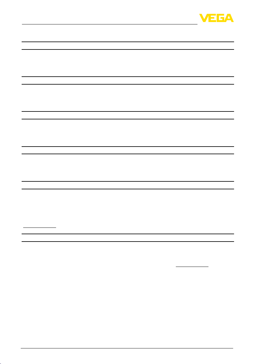
9 Anexo
Ʋ en el rango -20 … 0 °C (-4 … +32 °F) ≤ 0,2 %/10 K
Visualizar
Indicación de funcionamiento
Ʋ LED amarillo Enciende con circuito de salida de corriente conectado
Ʋ LED corriente de respuesta < 2 mA
Condiciones ambientales
Temperatura ambiente -20 … +50 °C (-4 … +122 °F)
Temperatura de almacenaje y transporte -20 … +70 °C (-4 … +158 °F)
Categoría de clima según EN 60654-1, clase B2
Medidas de protección eléctrica
Grado de protección IP 20
Categoría de sobretensión II
Clase de aislamiento I
Medidas de separación eléctrica
Separación segura entre todos los circuitos de corriente según VDE 0106 parte 1
Ʋ Tensión de referencia 253 V
Ʋ Resistencia al aislamiento 3,75 kV
Seguridad funcional (SIL)
El equipo se puede emplear en sistemas de seguridad instrumentados según IEC 61508/
IEC 61511-1 ( Seguridad de funcionamiento).
Si el equipo se pide de fábrica con calicación SIL, entonces el Safety Manual correspondiente
con informaciones detalladas sobre el tema "Seguridad funcional (SIL)" es parte del suministro.
Si el equipo se pide de fábrica sin calicación SIL, el Safety Manual correspondiente está en
"www.vega.com", "Downloads", "Homologaciones".
Homologaciones
Los equipos con homologación pueden tener datos técnicos diferentes en dependencia de la
versión.
Para esos equipos hay que considerar los documentos de autorización correspondientes. Los mismos forman parte del alcance de suministros o se pueden descargar de www.vega.com a través
de "VEGA Tools" y " serial number search" así como a través de "Downloads" y "Homologaciones".
40
VEGATRENN 149A Ex • Ex-separador para 4 … 20 mA/HART
24816-01-131025
Page 41

9.2 Medidas
9 Anexo
22,5 mm
(0.89")
on
CONNECT
149AEx
Abb. 28: Medidas VEGATRENN 149A Ex
112 mm (4.41")
96 mm (3.78")
110 mm (4.33")
24816-01-131025
VEGATRENN 149A Ex • Ex-separador para 4 … 20 mA/HART
41
Page 42

Notes
42
24816-01-131025
VEGATRENN 149A Ex • Ex-Speisetrenner für 4 … 20 mA/HART
Page 43

Notes
24816-01-131025
VEGATRENN 149A Ex • Ex-Speisetrenner für 4 … 20 mA/HART
43
Page 44

Printing date:
Die Angaben über Lieferumfang, Anwendung, Einsatz und Betriebsbedingungen der
Sensoren und Auswertsysteme entsprechen den zum Zeitpunkt der Drucklegung
vorhandenen Kenntnissen.
All statements concerning scope of delivery, application, practical use and operating
conditions of the sensors and processing systems correspond to the information
available at the time of printing.
Les indications de ce manuel concernant la livraison, l'application et les conditions
de service des capteurs et systèmes d'exploitation répondent aux connaissances
existantes au moment de l'impression.
Las informaciones acera del alcance de suministros, aplicación, uso y condiciones
de funcionamiento de los sensores y los sistemas de análisis corresponden con los
conocimientos existentes al momento de la impresión.
Änderungen vorbehalten Subject to change without prior notice Sous réserve
de modications Reservado el derecho de modicación
© VEGA Grieshaber KG, Schiltach/Germany 2013
VEGA Grieshaber KG
Am Hohenstein 113
77761 Schiltach
Germany
Phone +49 7836 50-0
Fax +49 7836 50-201
E-mail: info.de@vega.com
www.vega.com
24816-01-131025
 Loading...