

Page 1
Operating Instructions
VEGATOR 632
Signal conditioning instrument
Document ID:
35243
conditioning instruments
and communication
Signal
Page 2

Contents
Contents
1 About this document
1.1 Function. . . . . . . . . . . . . . . . . . . . . . . . . . . . . . . . . .
1.2 Target group . . . . . . . . . . . . . . . . . . . . . . . . . . . . . .
1.3 Symbolism used . . . . . . . . . . . . . . . . . . . . . . . . . . . .
2 For your safety
2.1 Authorised personnel . . . . . . . . . . . . . . . . . . . . . . . .
2.2 Appropriate use . . . . . . . . . . . . . . . . . . . . . . . . . . . .
2.3 Warning about misuse . . . . . . . . . . . . . . . . . . . . . . .
2.4 General safety instructions . . . . . . . . . . . . . . . . . . . .
2.5 CE conformity . . . . . . . . . . . . . . . . . . . . . . . . . . . . .
2.6 Safety instructions for Ex areas . . . . . . . . . . . . . . . . .
2.7 Environmental instructions. . . . . . . . . . . . . . . . . . . . .
3 Product description
3.1 Structure . . . . . . . . . . . . . . . . . . . . . . . . . . . . . . . . .
3.2 Principle of operation . . . . . . . . . . . . . . . . . . . . . . . .
3.3 Operation. . . . . . . . . . . . . . . . . . . . . . . . . . . . . . . . .
3.4 Packaging, transport and storage . . . . . . . . . . . . . . .
4 Mounting
4.1 General instructions . . . . . . . . . . . . . . . . . . . . . . . . .
4.2 Instructions for installation . . . . . . . . . . . . . . . . . . . . .
5 Connecting to power supply
5.1 Preparing the connection . . . . . . . . . . . . . . . . . . . . .
5.2 Connection procedure. . . . . . . . . . . . . . . . . . . . . . . .
5.3 Wiring plan. . . . . . . . . . . . . . . . . . . . . . . . . . . . . . . .
4
4
4
5
5
5
5
6
6
6
7
7
8
8
10
10
12
13
13
6 Adjustment elements
6.1 Adjustment elements - Overview . . . . . . . . . . . . . . . .
7 Set up - Single channel control (level detection)
7.1 Adjust relay function . . . . . . . . . . . . . . . . . . . . . . . . .
7.2 Sensitivity adjustment . . . . . . . . . . . . . . . . . . . . . . . .
7.3 Adjust switching delay . . . . . . . . . . . . . . . . . . . . . . .
7.4 Activate line break monitoring . . . . . . . . . . . . . . . . . .
7.5 Master/Slave function . . . . . . . . . . . . . . . . . . . . . . . .
8 Set up - Two-point control Δs (pump control)
8.1 Adjust relay function . . . . . . . . . . . . . . . . . . . . . . . . .
8.2 Adjustment. . . . . . . . . . . . . . . . . . . . . . . . . . . . . . . .
8.3 Adjust switching delay . . . . . . . . . . . . . . . . . . . . . . .
8.4 Activate line break monitoring . . . . . . . . . . . . . . . . . .
8.5 Master/Slave function . . . . . . . . . . . . . . . . . . . . . . . .
9 Set up - Two-channel control
9.1 Adjust relay function . . . . . . . . . . . . . . . . . . . . . . . . .
2 VEGATOR 632 • Signal conditioning instrument
19
23
25
27
27
28
29
31
33
34
34
35
35243-EN-120228
Page 3

Contents
9.2 Adjustment. . . . . . . . . . . . . . . . . . . . . . . . . . . . . . . .
9.3 Adjust switching delay . . . . . . . . . . . . . . . . . . . . . . .
9.4 Activate line break monitoring . . . . . . . . . . . . . . . . . .
9.5 Master/Slave function . . . . . . . . . . . . . . . . . . . . . . . .
10 Set up - Four-channel control
10.1 General information . . . . . . . . . . . . . . . . . . . . . . . . .
10.2 Adjust relay function . . . . . . . . . . . . . . . . . . . . . . . . .
10.3 Adjustment. . . . . . . . . . . . . . . . . . . . . . . . . . . . . . . .
10.4 Adjust switching delay . . . . . . . . . . . . . . . . . . . . . . .
10.5 Activate line break monitoring . . . . . . . . . . . . . . . . . .
10.6 Master/Slave function . . . . . . . . . . . . . . . . . . . . . . . .
11 Switching examples
11.1 Single channel operation. . . . . . . . . . . . . . . . . . . . . .
11.2 Two-channel operation . . . . . . . . . . . . . . . . . . . . . . .
11.3 Two-point control . . . . . . . . . . . . . . . . . . . . . . . . . . .
11.4 Four-channel operation . . . . . . . . . . . . . . . . . . . . . . .
11.5 Two-point control and two-channel operation . . . . . . .
12 Maintenance and fault rectification
12.1 Maintaining . . . . . . . . . . . . . . . . . . . . . . . . . . . . . . .
12.2 Remove interferences . . . . . . . . . . . . . . . . . . . . . . . .
12.3 Function test . . . . . . . . . . . . . . . . . . . . . . . . . . . . . .
12.4 Instrument repair . . . . . . . . . . . . . . . . . . . . . . . . . . .
13 Dismounting
13.1 Dismounting steps . . . . . . . . . . . . . . . . . . . . . . . . . .
13.2 Disposal . . . . . . . . . . . . . . . . . . . . . . . . . . . . . . . . .
37
39
39
40
41
41
41
41
41
42
43
45
46
48
49
50
50
51
52
53
53
14 Supplement
14.1 Technical data . . . . . . . . . . . . . . . . . . . . . . . . . . . . .
Supplementary documentation
Information:
Supplementary documents appropriate to the ordered version come
with the delivery. You can find them listed in chapter "Product
description".
Editing status: 2012-02-20
35243-EN-120228
VEGATOR 632 • Signal conditioning instrument 3
54
Page 4
1 About this document
1 About this document
1.1 Function
This operating instructions manual provides all the information you
need for mounting, connection and setup as well as important
instructions for maintenance and fault rectification. Please read this
information before putting t he instrument into operation and keep this
manual accessible in the immediate vicinity of the device.
1.2 Target group
This operating instructions manual is directed to trained qualified
personnel. The contents of this manual should be made available to
these personnel and put into practice by them.
1.3 Symbolism used
Information, tip, note
This symbol indicates helpful additional information.
Caution: If this warning is ignored, faults or malfunctions can
result.
Warning: If this warning is ignored, injury to persons and/or serious
damage to the instrument can result.
Danger: If this warning is ignored, serious injury to persons and/or
destruction of the instrument can result.
Ex applications
This symbol indicates special instructions for Ex applications.
l List
The dot set in front indicates a list with no implied sequence.
à Action
This arrow indicates a single action.
1 Sequence
Numbers set in front indicate successive steps in a procedure.
4 VEGATOR 632 • Signal conditioning instrument
35243-EN-120228
Page 5

2 For your safety
2 For your safety
2.1 Authorised personnel
All operations described in this operating instructions manual must be
carried out only by trained specialist personnel authorised by the plant
operator.
During work on and with the device the required personal protective
equipment must always be worn.
2.2 Appropriate use
VEGATOR 632 is a universal signal conditioning instrument for
connection of a level switch.
You can find detailed information on the application range in chapter
"Product description".
Operational reliability is ensured only if the instrument is properly used
according to the specifications in the operating instructions manual as
well as possible supplementary instructions.
For safety and warranty reasons, any invasive work on the device
beyond that described in the operating instructions manual may be
carried out only by personnel authorised by the manufacturer. Arbitrary
conversions or modifications are explicitly forbidden.
2.3 Warning about misuse
Inappropriate or incorrect use of the instrument can give rise to
application-specific hazards, e.g. vessel overfill or damage to system
components through incorrect mounting or adjustment.
2.4 General safety instructions
This is a high-tech instrument requiring the strict observance of
standard regulations and guidelines. The user must take note of the
safety instructions in this operating instructions manual, the countryspecific installation standards as well as all prevailing safety
regulations and accident prevention rules.
The instrument must only be operated in a technically flawless and
reliable condition. The operator is responsible for trouble-free
operation of the instrument.
During the entire duration of use, the user is obliged to determine the
compliance of the necessary occupational safety measures with the
current valid rules and regulations and also take note of new
regulations.
35243-EN-120228
VEGATOR 632 • Signal conditioning instrument 5
Page 6

2 For your safety
2.5 CE conformity
This device fulfills the legal requirements of the applicable EC
guidelines. By attaching the CE mark, VEGA provides a confirmation
of successful testing. You can find the CE conformity declaration in the
download area of
www.vega.com.
2.6 Safety instructions for Ex areas
Please note the Ex-specific safety information for installation and
operation in Ex areas. These safety instructions are part of the
operating instructions manual and come with the Ex-approved
instruments.
2.7 Environmental instructions
Protection of the environment is one of our most important duties. That
is why we have introduced an environment management system with
the goal of continuously improving company environmental protection.
The environment management system is certified according to DIN
EN ISO 14001.
Please help us fulfil this obligation by observing the environmental
instructions in this manual:
l Chapter "Packaging, transport and storage"
l Chapter "Disposal"
6 VEGATOR 632 • Signal conditioning instrument
35243-EN-120228
Page 7
3 Product description
1
1
3.1 Structure
3 Product description
Scope of delivery
Constituent parts
Type label
The scope of delivery encompasses:
l VEGATOR 632 signal conditioning instrument
l Documentation
- this operating instructions manual
- Ex-specific "Safety instructions" (with Ex-versions)
- if necessary, further certificates
VEGATOR 632 consists of:
l VEGATOR 632 signal conditioning instrument
Fig. 1: VEGATOR 632
1 Pluggable terminal blocks
The type label contains the most important data for identification and
use of the instrument:
l Article number
l Serial number
l Technical data
l Article numbers, documentation
l Information about connection and adjustment of the instrument
The serial number allows you to access the delivery data of the
instrument via www.vega.com, "VEGA Tools" and "serial number
search".
3.2 Principle of operation
Application area
35243-EN-120228
VEGATOR 632 • Signal conditioning instrument 7
VEGATOR 632 is a single signal conditioning instrument with two
channels (relay) for processing the signals of conductive probes.
Page 8

3 Product description
Functional principle
The following switching functions are possible:
l Single channel control (simple level detection)
l Two-point control (pump control)
l Two-channel control (two separate switching points)
l Four-channel control or combination of two-point and two-channel
control (with two VEGATOR 632)
The VEGATOR 632 signal conditioning instrument powers connected
sensors and simultaneously processes their measuring signals.
It delivers a small alternating current to the measuring cell via the
signal cable. Electrolytic decomposition of the electrode rods and the
medium is avoided by using alternating current.
The cable is connected to the measurement loop or the metallic vessel
and the probe.
When the medium reaches the switching point of the sensor, the
voltage on the sensor drops. The output relays then switch according
to the set mode.
Voltage supply
Packaging
Transport
Transport inspection
Detailed information about the power supp ly can be found in chapter
"Technical data".
3.3 Operation
The damping and the mode can be adjusted on the signal conditioning
instrument via the slide switch. The instrument function can be
preadjusted with a DIL switch block.
The switching point can be adjusted with a potentiometer.
3.4 Packaging, transport and storage
Your instrument was protected by packaging during transport. Its
capacity to handle normal loads during transport is assured by a test
according to DIN EN 24180.
The packaging of standard instruments consists of environmentfriendly, recyclable cardboard. For special versions, PE foam or PE foil
is also us ed. Dispose of the packaging material via specialised
recycling companies.
Transport must be carried out under consideration of the notes on the
transport packaging. Nonobservance of these instructions can cause
damage to the device.
The delivery must be checked for completeness and possible transit
damage immediately at receipt. Ascertained transit damage or
concealed defects must be appropriately dealt with.
35243-EN-120228
8 VEGATOR 632 • Signal conditioning instrument
Page 9

3 Product description
Storage
Storage and transport
temperature
Up to the time of installation, the packages must be left closed and
stored according to the orientation and storage markings on the
outside.
Unless otherwise indicated, the packages must be stored only under
the following conditions:
l Not in the open
l Dry and dust free
l Not exposed to corrosive media
l Protected against solar radiation
l Avoiding mechanical shock and vibration
l Storage and transport temperature see chapter "Supplement -
Technical data - Ambient conditions"
l Relative humidity 20 … 85 %
35243-EN-120228
VEGATOR 632 • Signal conditioning instrument 9
Page 10
a
a
a
? ? ? ? ?
E
X
E
X
E
X
4 Mounting
4 Mounting
4.1 General instructions
Installation location
Front plate
Protected mounting lo-
cation
Installation
Min. distances
VEGATOR 632 signal conditioning instrument for mounting on carrier
rail according to EN 60715 TH 35 x 7.5 or EN 60715 TH 35 x 15.
The adjustment elements of VEGATOR 632 are protected under a
hinged front plate against unauthorised or inadvertent adjustment.
VEGATOR 632 must be mounted outside the hazardous area in a
switching cabinet (at least protection rating IP 55).
For moisture-protected mounting outside the switching cabinet, we
offer an insulated protective housing with transparent cover (IP 65) for
surface mounting.
4.2 Instructions for installation
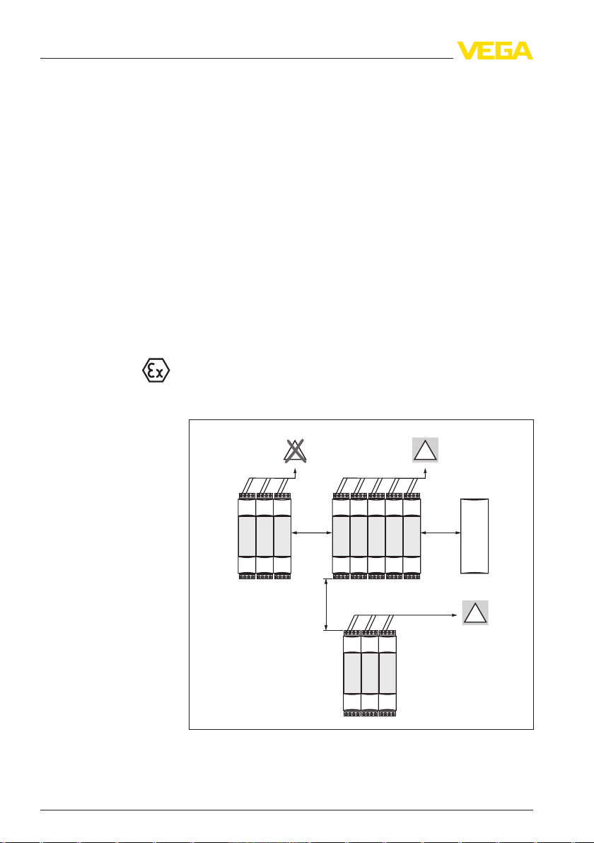
A VEGATOR 632 in Ex version is an auxiliary, intrinsically safe
instrument and may not be installed in explosion-endangered areas.
Please keep the following min. distances when mounting.
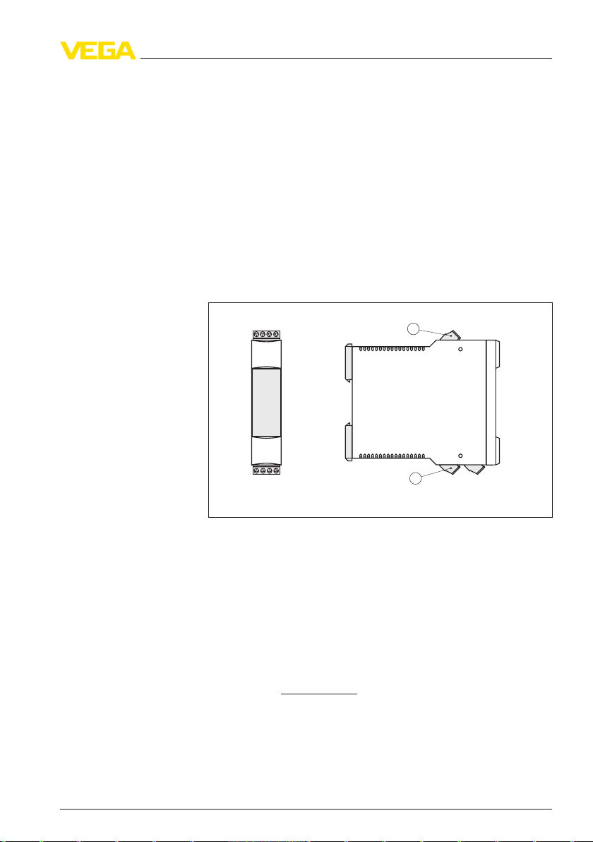
Fig. 2: Min. distances to other instruments
a Distance ≥ 50 mm (1.97 in)
10 VEGATOR 632 • Signal conditioning instrument
35243-EN-120228
Page 11
1
1
2
b
b
a
a
4 Mounting
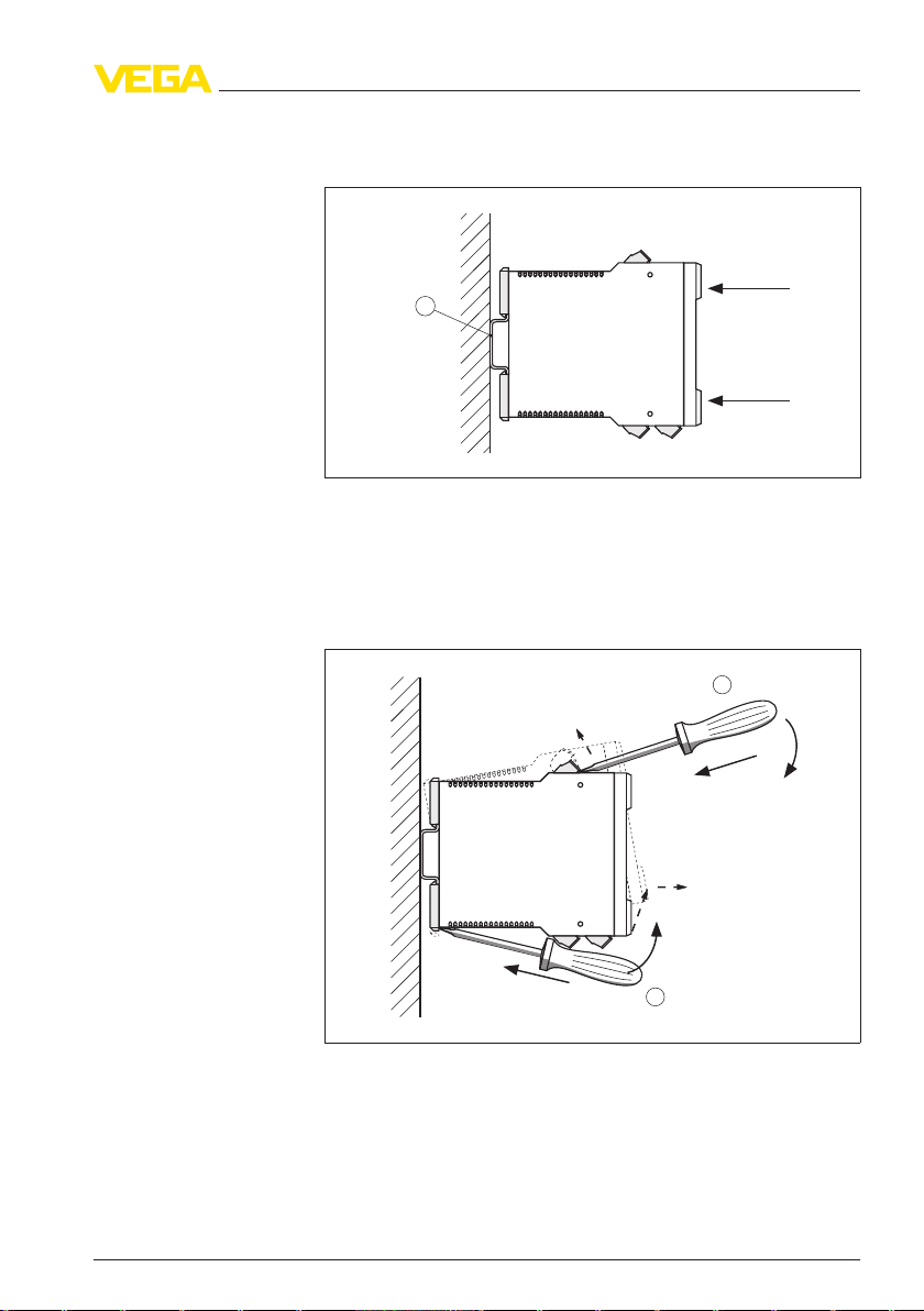
Carrier rail mounting
Dismounting
Snap in the instrument vertically on a suitable carrier rail (EN 60715
TH 35 x 7.5 or EN 60715 TH 35 x 15).
Fig. 3: Mounting of the signal conditioning instrument
1 Carrier rail EN 60715 TH 35
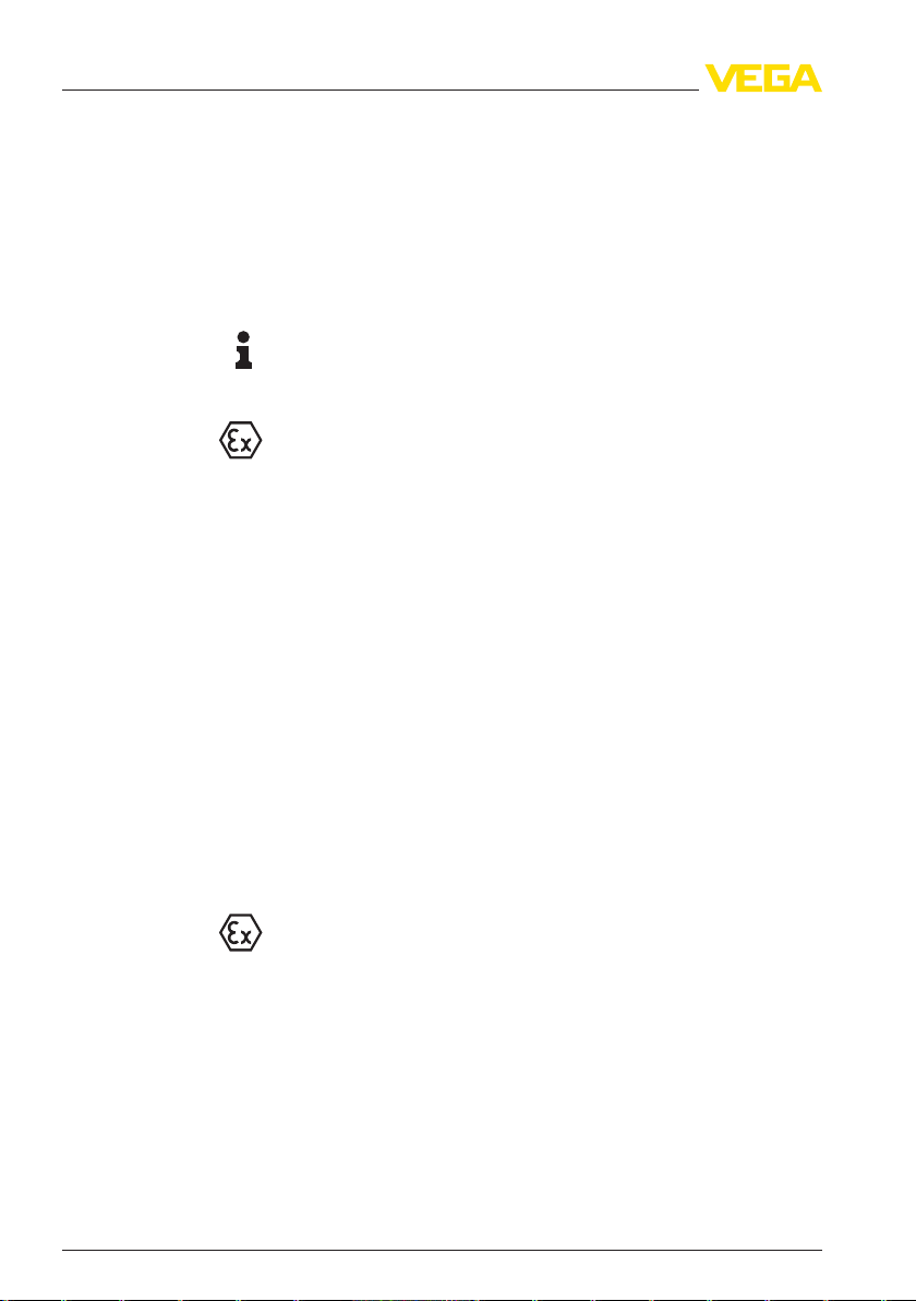
Dismount the instrument in the following sequence.
1 Switch off power supply
Fig. 4: Dismounting of the signal conditioning instrument
2 Remove the terminal blocks with a screwdriver ①
3 Open the slide with a screwdriver ②
4 Flip up the signal conditioning instrument and remove it from the
35243-EN-120228
VEGATOR 632 • Signal conditioning instrument 11
carrier rail
Page 12
5 Connecting to power supply
5 Connecting to power supply
5.1 Preparing the connection
Note safety instructions
Take note of sa-
fety instructions
for Ex applications
Select power supply
Selecting connection
cable
Cable screening and
grounding
Always keep in mind the following safety instructions:
l Connect only in the complete absence of line voltage
l If overvoltage surges are expected, overvoltage arresters should
be installed
Tip:
We recommend VEGA overvoltage arresters B61-300 (power supply
VEGATOR 632) and B62-36G (sensor supply).
In hazardous areas you must take note of the respective regulations,
conformity and type approval certificates of the sensors and power
supply units.
The power supply can be 85 … 253 V AC, 50/60 Hz or 20 … 60 V DC.
The operating voltage of VEGATOR 632 is connected with standard
cable according to the national installation standards. The line
resistance must be max. 25 Ω per wire. If electromagnetic interference
is expected which is above the test values of EN 61326 for industrial
areas, screened cable should be used.
If screened cable is necessary, connect the cable screen on both ends
to ground potential. In the sensor, the screen must be connected
directly to the internal ground terminal. The ground terminal on the
outside of the housing must be connected to the potential equalisation
(low impedance).
If potential equalisation currents are expected, the connection on the
processing side must be made via a ceramic capacitor (e. g. 1 nF,
1500 V). The low frequency potential equalisation currents are thus
suppressed, but the protective effect against high frequency interference si gnals remains.
Select connection cable for Ex
applications
12 VEGATOR 632 • Signal conditioning instrument
Take note of the corresponding installation regulations for Ex
applications.
35243-EN-120228
Page 13
L1L+N
L–
7 8 9 10
4 5 6 17
1 2
15 16
CH2
CH1
Master/
Slave
1 2 3 4
5
6 7
1
2
15
16
4
5
6
17
7
8
9
10
4
5
6
17
TOR
149A
ON
5 Connecting to power supply
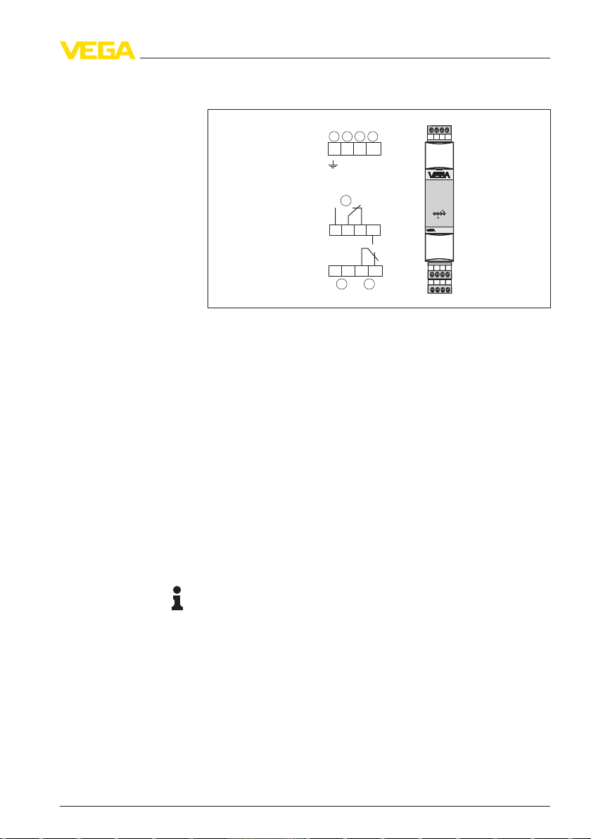
5.2 Connection procedure
Fig. 5: Terminal assignment
1 Ground
2 Sensor input - Channel 1 (CH 1)
3 Sensor input - Channel 2 (CH 2)
4 Master/Slave
5 Level relay 1
6 Voltage supply
7 Level relay 2 or operating relay
Move on to electrical connection and proceed as follows:
1 Snap VEGATOR 632 onto the carrier rail
2 Connect the sensor cable to terminals 7 to 10 (see the following
wiring plans)
3 Connect relay outputs (4 to 6 and 15 to 17)
4 Connect power supply (switched off) to terminal 1 and 2
The electrical connection is finished.
5.3 Wiring plan
Note:
In conductive vessels, the ground cable has contact to the grounded
vessel via the process fitting.
In non-conductive vessels, the probe requires a ground rod which is
connected to the ground terminal of VEGATOR 632.
Line monitoring
35243-EN-120228
VEGATOR 632 • Signal conditioning instrument 13
The line break monitoring or alarm function defines the function of the
signal conditioning instrument in case of failure.
The line monitoring is required for probes with approval according to
WHG (WRA) or Ex.
To realize a line monitoring, an additional electronics must be
integrated in the connection housing of the probe.
Page 14
1
2
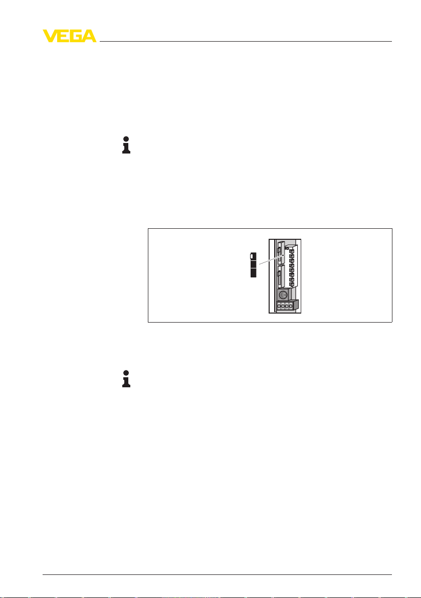
5 Connecting to power supply
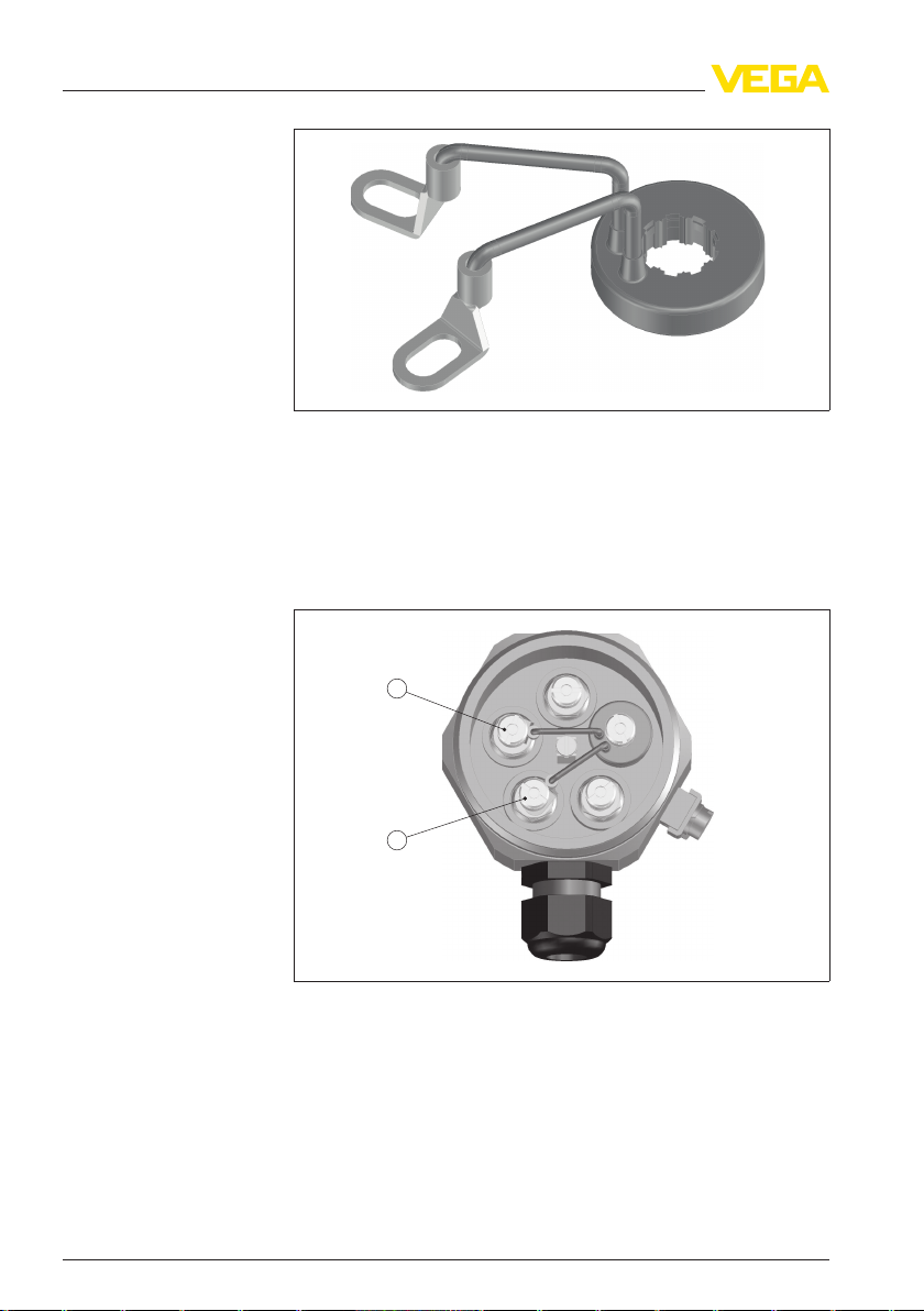
Fig. 6: Additional electronics for line break monitoring in conjunction with a
conductive probe
1 Connect the eyelet according to the following illustration.
Make sure that the eyelets have no contact to other metal parts.
2 Open one of the other terminals and attach the additional
electronics.
3 Tighten the terminal.
Fig. 7: Mounting of the additional electronics for line break monitoring
1 Connection to terminal 1 (ground rod = longest rod)
2 Connection to terminal 2 (max. rod = shortest rod)
3 Additional electronics for line break monitoring
If you are using a probe without additional electronics for line break
monitoring, a fault signal will be triggered.
Keep in mind that in case of a fault signal also the switching output will
be activated.
Only failures of channel 1 are monitored.
14 VEGATOR 632 • Signal conditioning instrument
35243-EN-120228
Page 15
1 2
2
1
6
1
2
15
16
4
5
6
17
7
8
9
10
4
5
6
17
TOR
149A
ON
L1L+N
L–
7 8 9 10
4 5 6 17
1 2
15 16
CH2
CH1
Master/
Slave
3
5
4
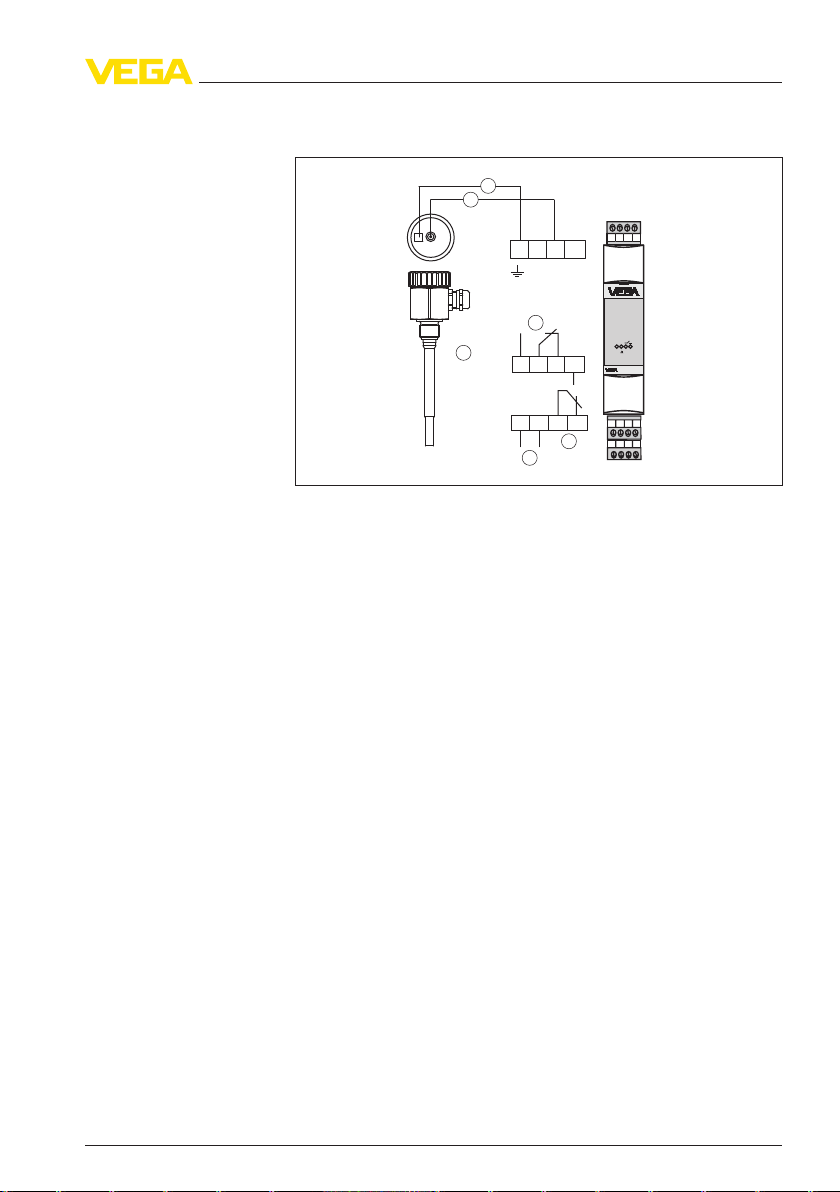
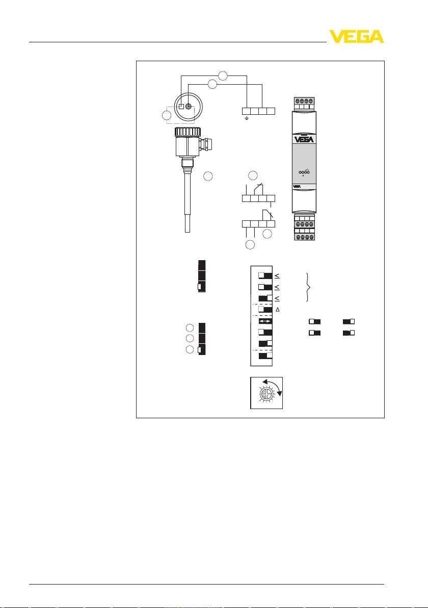
Level detection in conductive vessels
5 Connecting to power supply
Take note of the operating instructions of the conductive probe.
Fig. 8: Level detection in metallic (conductive) vessels
1 Ground
2 max. - channel 1 (CH 1)
3 Level relay 1
4 Level relay 2 or fail safe relay
5 Voltage supply
6 Probe, e.g. EL1
You can find detailed information under "Set up - Single point control"
as well as under "Switching examples".
35243-EN-120228
VEGATOR 632 • Signal conditioning instrument 15
Page 16
1
2
2
1
6
1
2
1
2
15
16
4
5
6
17
7
8
9
10
4
5
6
17
TOR
149A
ON
L1L+N
L–
7 8 9 10
4 5 6 17
1 2
15 16
CH2
CH1
Master/
Slave
3
5
4
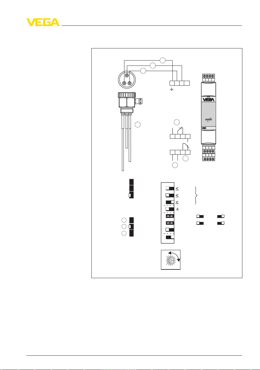
5 Connecting to power supply
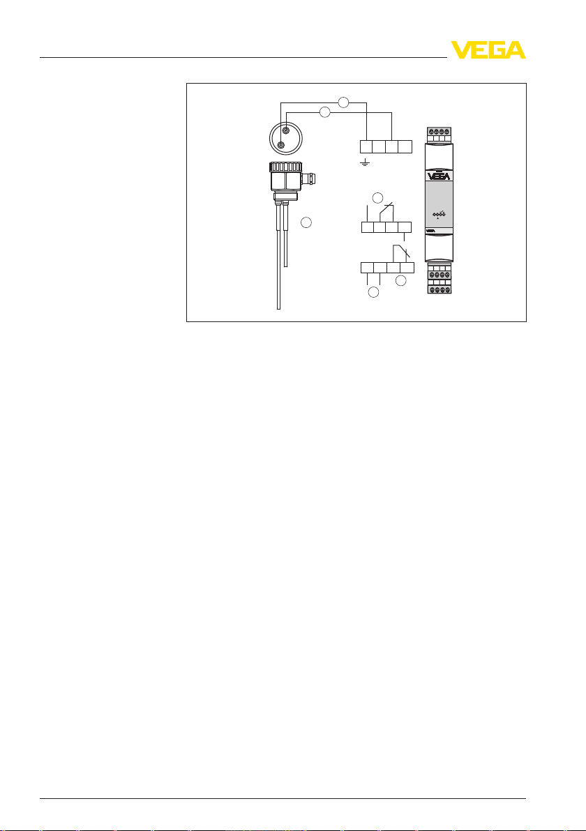
Level detection in nonconductive vessels
Fig. 9: Level detection in non-conductive vessels
1 Ground
2 max. - channel 1 (CH 1)
3 Level relay 1
4 Level relay 2 or fail safe relay
5 Voltage supply
6 Probe, e.g. EL3
You can find detailed information under "Set up - Single point control"
as well as under "Switching examples".
16 VEGATOR 632 • Signal conditioning instrument
35243-EN-120228
Page 17
1 3
2
2
3
1
7
1
2
3
1
2
15
16
4
5
6
17
7
8
9
10
4
5
6
17
TOR
149A
ON
L1L+N
L–
7 8 9 10
4 5 6 17
1 2
15 16
CH2
CH1
Master/
Slave
4
6
5
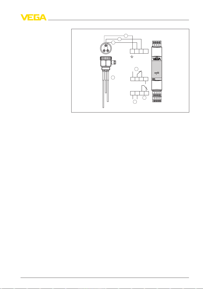
Two-point control (min./
max. control)
5 Connecting to power supply
Fig. 10: Two-point control
1 Ground
2 max. - channel 1 (CH 1)
3 min. - channel 2 (CH 2)
4 Level relay 1
5 Level relay 2 or fail safe relay
6 Voltage supply
7 Probe, e.g. EL3
You can find detailed information under "Set up - Two-point control" as
well as under "Switching examples".
35243-EN-120228
VEGATOR 632 • Signal conditioning instrument 17
Page 18
1
2 3
4
5
1
4
2
5
3
3
4
5
1
9
A B
2
1
2
15
16
4
5
6
17
7
8
9
10
4
5
6
17
TOR
149A
ON
L1L+N
L–
7 8 9 10
4 5 6 17
1 2
15 16
CH2
CH1
Master/
Slave
6
8
7
1
2
15
16
4
5
6
17
7
8
9
10
4
5
6
17
TOR
149A
ON
L1L+N
L–
7 8 9 10
4 5 6 17
1 2
15 16
CH2
CH1
Master/
Slave
6
8
7
5 Connecting to power supply
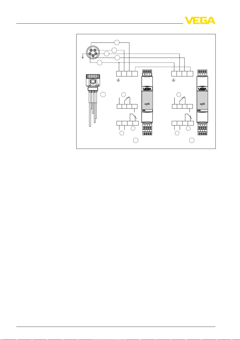
Four-channel control
with two signal conditioning instruments
Fig. 11: Four-channel control with two signal conditioning instruments VEGATOR
632
1 Ground
2 max. - channel 1 (CH 1)
3 min. - channel 2 (CH 2)
4 min. - channel 2 (CH 2)
5 max. - channel 1 (CH 1)
6 Level relay 1
7 Level relay 2 or fail safe relay
8 Voltage supply
9 Probe, e.g. EL3
A Min./max. control (signal conditioning instrument 1 - Master)
B Min./max. control (signal conditioning instrument 2 - Slave)
You can find detailed information under "Set up - Four-channel control"
as well as under "Switching examples".
18 VEGATOR 632 • Signal conditioning instrument
35243-EN-120228
Page 19

1 2 3 4 5 6 7 8
O
N
7
8
4
5
6
15
16
L1
N
L+ L-
1
2
9
10
CH 2
CH
1
master
/
slave
output
mode
delay
s
alarm
master/
slave
range
1 2 3 4 5 6 7 8
calibration
CH1
CH2
17
min/
max
3
1
3362
C
B
A
D
E
6 Adjustment elements
6 Adjustment elements
6.1 Adjustment elements - Overview
The following adjustment elements are located below the cover.
DIL switch block (A)
35243-EN-120228
VEGATOR 632 • Signal conditioning instrument 19
Fig. 12: VEGATOR 632 - Adjustment elements
A DIL switch block
B Potentiometer for switching point adjustment
C Control lamps
D Slid switch for mode adjustment
E Slide switch for setting the switching delay
SIL switch block with 8 switches. The individual switches are assigned
as follows:
Page 20

1 KΩ
10 KΩ
200 KΩ
s
CH1
CH2
Alarm
Slave/Master
min.
min.
max.
max.
off on
1
2
3
4
5
6
7
8
Calibration
3
1
6 Adjustment elements
(numbering from top to bottom)
Fig. 13: DIL switch block (A)
1 Sensitivity adjustment - range up to 1 kΩ
2 Sensitivity adjustment - range up to 10 kΩ
3 Sensitivity adjustment - range up to 200 kΩ
4 Two-point control
5 Mode - channel 1 (CH 1)
6 Mode - channel 2 (CH 2)
7 Line monitoring (alarm)
8 Master/Slave adjustment
l A1 - Sensitivity adjustment - range up to 1 kΩ
l A2 - Sensitivity adjustment - range up to 10 kΩ
l A3 - Sensitivity adjustment - range up to 200 kΩ
l A4 - Two-point control
l A5 - Mode - Channel 1 (CH 1)
- off: Max. detection or overflow protection
- on: Min. detection or dry run detection
l A6 - Mode - Channel 2 (CH 2)
- off: Max. detection or overflow protection
- on: Min. detection or dry run detection
l A7 - Line monitoring (alarm)
l A8 - Master/Slave adjustment (on = Master)
Potentiometer for switching point adjustment
(B)
20 VEGATOR 632 • Signal conditioning instrument
A potentiometer for switching point adaptation is located below the
cover of the signal conditioning instrument. With this potentiometer you
can adapt the measuring system to the conductivity of the product.
Fig. 14: Potentiometer for switching point adjustment (B)
35243-EN-120228
Page 21

TOR
149A
ON
3
4
1
2
6 Adjustment elements
Note:
When carrying out switching point adjustments keep in mind that there
is a switching delay of 0.5 sec between the moment when the
switching point is reached and the moment when the switching
function is triggered. The potentiometer must therefore be turned
slowly.
A possible additional switching delay should only be switched on after
the adjustment.
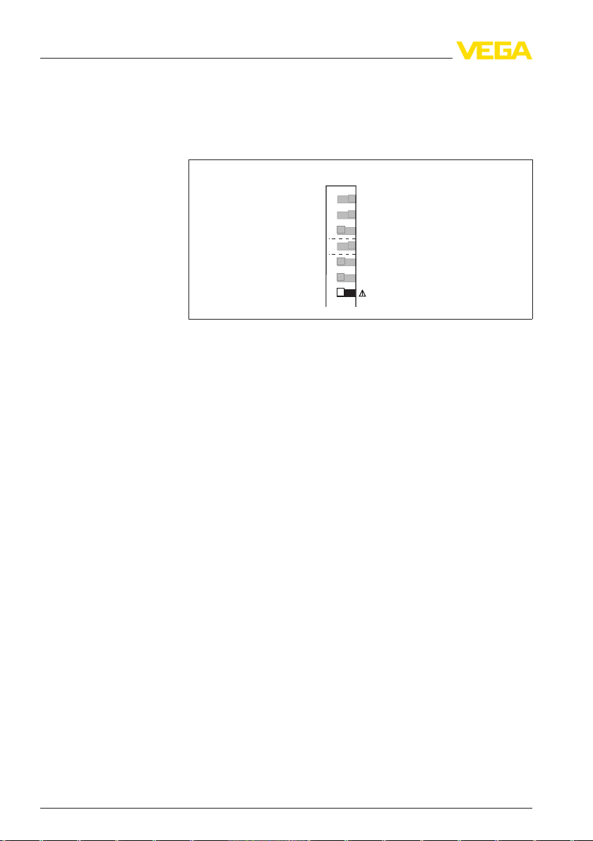
Signal lamps (C)
Control lamps (LED) in the front plate indicate operation, switching
status and fault signal.
Fig. 15: Control lamps in the instrument front (C)
1 Control lamp - Operating voltage - green (gn)
2 Control lamp - Fault signal - red (rd)
3 Control lamp - Switching status channel 2 - yellow (ye)
4 Control lamp - Switching status channel 1 - yellow (ye)
l Green (gn)
- Operating control lamp
- Mains voltage on, instrument is operating
l Red (rd)
- Failure lamp
- Fault on the sensor circuit due to sensor failure or line break
- If the fail safe relay is deenergized, the red failure lamp will
light
l Yellow (ye)
- Relay control lamps
- The yellow relay control lamps react depending on the set
mode (min./max.)
- The relay control lamp generally indicates the activated
(energized) condition of the relay
- A dark relay control lamp means that the relay is deenergised
35243-EN-120228
VEGATOR 632 • Signal conditioning instrument 21
Page 22

1 2 3 4 5 6 7
8
O
N
3
1
3362
CH1 output parallel
CH2 output separate
CH1 with alarm
O
N
3
1
3362
6 s
3 s
0,5 s
1 2 3 4 5 6 7
8
6 Adjustment elements
Slide switch for adjustment of the relay outputs (D)
Slide switch for setting
the switching delay (E)
3-step switch for mode adjustment of the second output relay. The
individual switch positions are assigned as follows:
Fig. 16: Slide switch for adjustment of the relay outputs (D)
l CH 1 output parallel - Both relay outputs switch in parallel. The
second relay (15 - 17) switches analogue to relay 1 (4 - 6)
l CH 2 output separate - Two-point control or two independent relay
outputs. The second relay (15 - 17) switches independently of
relay 1 (4 - 6)
l CH 1 with alarm - Fault signal with relay output 2. The second relay
(4 - 6) triggers a fault signal.
3-step switch for adjustment of the switching delay. The adjusted
switching delay applies to the switch on and switch off delay.
Fig. 17: Slide switch for setting the switching delay (E)
l 6 s
l 3 s
l 0.5 s
22 VEGATOR 632 • Signal conditioning instrument
35243-EN-120228
Page 23

1 2 3 4 5 6 7
8
O
N
3
1
3362
CH1 output parallel
CH2 output separate
CH1 with alarm
64 5
1617 15
ye yegn rd
64 5
1617 15
ye yegn rd
64 5
1617 15
ye yegn rd
7 Set up - Single channel control (level detection)
7 Set up - Single channel control (level
detection)
7.1 Adjust relay function
Adjustment of the relay
outputs (slide switch D)
CH 1 output parallel
3-step switch. The individual switch positions are assigned as follows:
Fig. 18: Slide switch for adjustment of the relay outputs (D)
l CH 1 output parallel - Both relay outputs switch in parallel
l CH 2 output separate - Relay outputs switch separately
l CH 1 with alarm - Fault signal with relay output 2
The following charts provide an overview of the relay switching
conditions and the control lamps depending on the adjusted mode and
level.
Level detection with one switching point
l Min. (dry run protection) or mac. (overfill protection)
l Channel 1 (relay 1) and channel 2 (relay 2) switch in parallel (CH 1
output parallel)
Mode Level Channel 1 Channel 2 Control lamps
max.
35243-EN-120228
VEGATOR 632 • Signal conditioning instrument 23
max.
min.
Page 24

64 5
1617 15
ye yegn rd
64 5
1617 15
ye yegn rd
64 5
1617 15
ye yegn rd
64 5
1617 15
ye yegn rd
64 5
1617 15
ye yegn rd
64 5
1617 15
ye yegn rd
64 5
1617 15
ye yegn rd
7 Set up - Single channel control (level detection)
Mode Level Channel 1 Channel 2 Control lamps
min.
CH 2 output separate
CH 1 with alarm
In this switch position, channel 2 (relay 2) has no switching function
and remains deengerised.
Switching reaction of channel 1 see "CH 1 output parallel".
Level detection with one switching point - Fault signal with relay
output 2
l Min. (dry run protection) or mac. (overfill protection)
l Channel 1 (switching relay) and channel 2 (fail safe relay) - (CH 1
with alarm)
Mode Level Channel 1 Channel 2 Control lamps
max.
max.
min.
min.
Malfuncti-onany
Voltage in-
any
terruption
24 VEGATOR 632 • Signal conditioning instrument
35243-EN-120228
Page 25

1 KΩ
10 KΩ
200 KΩ
200 KΩ
CH1
CH2
max.
max.
off on
1
2
3
4
5
6
7
7 Set up - Single channel control (level detection)
7.2 Sensitivity adjustment
Medium: Non-conducti-
ve liquids
Standard adjustment for conductive liquids.
Specifications:
The probe is covered with medium by at least 1 cm.
1 Set DIL switch 1 to 3 on the DIL switch block (A) according to the
following illustration
Fig. 53: Medium: Conductive liquids up to 200 kΩ
2 Turn potentiometer (B) to complete left position
3 Turn potentiometer (B) slowly clockwise until the relay output
switches and the yellow control lamp changes condition
4 Turn the potentiometer approximately 15° in the same direction
5 If the relay output does not change, you have to switch to the next
range (10 kΩ).
If the relay output has switched, empty the vessel until the electrode is
uncovered.
The relay output must now switch again.
Medium: Liquids in the
resistance range up to
10 kΩ
Adjustment in liquids with resistance range up to 10 kΩ
Specifications:
The probe is covered with medium.
35243-EN-120228
VEGATOR 632 • Signal conditioning instrument 25
Page 26

1 KΩ
10 KΩ
200 KΩ
10 KΩ
CH1
CH2
max.
max.
off on
1
2
3
4
5
6
7
1 KΩ
10 KΩ
200 KΩ
1 KΩ
CH1
CH2
max.
max.
off on
1
2
3
4
5
6
7
7 Set up - Single channel control (level detection)
1 Set DIL switch 1 to 3 on the DIL switch block (A) according to the
following illustration
Fig. 54: Medium: Liquids in the resistance range up to 10 kΩ
2 Turn potentiometer (B) to complete left position
3 Turn potentiometer (B) slowly clockwise until the relay output
switches and the yellow control lamp changes condition
4 Turn the potentiometer approximately 15° in the same direction
5 If the relay output does not change, you have to switch to the next
range (1 kΩ).
If the relay output has switched, empty the vessel until the electrode is
uncovered.
The relay output must now switch again.
Medium: Liquids in the
resistance range up to
1 kΩ
Adjustment in liquids with resistance range up to 1 kΩ
Specifications:
The probe is covered with medium.
1 Set DIL switch 1 to 3 on the DIL switch block (A) according to the
following illustration
26 VEGATOR 632 • Signal conditioning instrument
Fig. 55: Medium: Liquids in the resistance range up to 1 kΩ
2 Turn potentiometer (B) to complete left position
35243-EN-120228
Page 27

O
N
3
1
3362
6 s
3 s
0,5 s
1 2 3 4 5 6 7
8
7 Set up - Single channel control (level detection)
3 Turn potentiometer (B) slowly clockwise until the relay output
switches and the yellow control lamp changes condition
4 Turn the potentiometer approximately 15° in the same direction
If the relay output has switched, empty the vessel until the electrode is
uncovered.
The relay output must now switch again.
Note:
A failure exists, if the relay output does not switch over even in the last
range. You will find instructions for fault rectification in chapter
"Maintenance and fault rectification".
7.3 Adjust switching delay
Adjustment of the swit-
ching delay (slide switch
E)
Adjust the switching delay for the instrument with the slide switch (E).
Fig. 56: Slide switch (E) for setting the switching delay
The adjusted switching delay refers to the switching function of the
relay and applies only to the switch on delay.
Note:
When carrying out switching point adjustments keep in mind that there
is a switching delay of 0.5 sec between the moment when the
switching point is reached and the moment when the switching
function is triggered. The potentiometer must therefore be turned
slowly.
A possible additional switching delay should only be switched on after
the adjustment.
The following switching delays can be selected with the 3-step switch.
l 6 s
l 3 s
l 0.5 s
7.4 Activate line break monitoring
35243-EN-120228
VEGATOR 632 • Signal conditioning instrument 27
The line break monitoring or alarm function defines the function of the
instrument in case of failure.
Page 28
Alarm
off on
1
2
3
4
5
6
7
7 Set up - Single channel control (level detection)
If you are using a probe without line break monitoring, a fault signal will
be triggered. In this case, set the switch (7) to off.
Only failures of channel 1 are monitored.
A failure is signalled via the red control lamp on the front plate.
Fig. 57: Switch block (A) with switch (7) for activation of the line break monitoring
(alarm)
You find detailed information on how to trigger a fault signal via the
second relay output in the previous chapter "Adjust relay function".
7.5 Master/Slave function
Definition of the instru-
ment as Master or Slave
Adjust the instrument as Master with switch 8 of the DIL switch block
(A).
(DIL switch block A)
28 VEGATOR 632 • Signal conditioning instrument
35243-EN-120228
Page 29

1 2 3 4 5 6 7
8
O
N
3
1
3362
CH1 output parallel
CH2 output separate
CH1 with alarm
64 5
1617 15
ye yegn rd
8 Set up - Two-point control Δs (pump control)
8 Set up - Two-point control Δs (pump
control)
8.1 Adjust relay function
Adjustment of the relay
outputs (slide switch D)
CH 1 output parallel
CH 2 output separate
3-step switch. The individual switch positions are assigned as follows:
Fig. 58: Slide switch for adjustment of the relay outputs (D)
l CH 1 output parallel - Both relay outputs switch in parallel
l CH 2 output separate - Relay outputs switch separately
l CH 1 with alarm - Fault signal with relay output 2
The following charts provide an overview of the relay switching
conditions and the control lamps depending on the adjusted mode and
level.
Output relay 2 operates like output relay 1. The function of the two
output relays is the same.
Switching condition of the two channels see "CH 2 output separate".
Two-point control (pump control) Δs - Overfill protection (max.)
Specifications:
l Overfill protection (max.) - DIL switch block (A) switch 5 and 6 to
off
l Channel 1 (relay 1) and channel 2 (relay 2) switch separately (the
respective mode is selectable for each relay)
l Two-point control (pump control) - DIL switch block (A) switch 4 to
on (Δs)
Mode Level Channel 1 Channel 2 Control lamps
Two-point
control max.
35243-EN-120228
VEGATOR 632 • Signal conditioning instrument 29
Page 30

64 5
1617 15
ye yegn rd
64 5
1617 15
ye yegn rd
64 5
1617 15
ye yegn rd
64 5
1617 15
ye yegn rd
64 5
1617 15
ye yegn rd
64 5
1617 15
ye yegn rd
64 5
1617 15
ye yegn rd
64 5
1617 15
ye yegn rd
8 Set up - Two-point control Δs (pump control)
Mode Level Channel 1 Channel 2 Control lamps
Two-point
control max.
Two-point
control max.
Two-point
control max.
Two-point
control max.
Two-point control (pump control) Δs - Dry run protection (min.)
Specifications:
l Dry run protection (min.) - DIL switch block (A) switch 5 and 6 to on
l Channel 1 (relay 1) and channel 2 (relay 2) switch separately (CH
2 output separate)
l Two-point control (pump control) - DIL switch block (A) switch 4 to
on (Δs)
Mode Level Channel 1 Channel 2 Control lamps
Two-point
control min.
Two-point
control min.
Two-point
control min.
Two-point
control min.
30 VEGATOR 632 • Signal conditioning instrument
35243-EN-120228
Page 31

64 5
1617 15
ye yegn rd
1 KΩ
10 KΩ
200 KΩ
200 KΩ
CH1
CH2
max.
max.
off on
1
2
3
4
5
6
7
8 Set up - Two-point control Δs (pump control)
Mode Level Channel 1 Channel 2 Control lamps
Two-point
control min.
CH 1 with alarm
Adjustment with con-
ductive liquids
Level detection with one switching point - Fault signal with relay
output 2
Switching reaction of channel 1 see "CH 2 output separate".
l Dry run protection (min.) or overfill protection (max.)
l Channel 1 (switching relay) and channel 2 (fail safe relay) - (CH 1
with alarm)
8.2 Adjustment
Standard adjustment for conductive liquids.
Specifications:
The probe is covered with medium.
1 Set DIL switch 1 to 3 on the DIL switch block (A) according to the
following illustration
Fig. 95: Conductive liquids up to 200 kΩ
2 Turn potentiometer (B) to complete left position
3 Turn potentiometer (B) slowly clockwise until the relay output
switches and the yellow control lamp changes condition
4 Turn the potentiometer approximately 15° in the same direction
5 If the relay output does not change, you have to switch to the next
range.
35243-EN-120228
VEGATOR 632 • Signal conditioning instrument 31
If the relay output has switched, empty the vessel until the electrode is
uncovered.
The relay output must now switch again.
Page 32

1 KΩ
10 KΩ
200 KΩ
10 KΩ
CH1
CH2
max.
max.
off on
1
2
3
4
5
6
7
8 Set up - Two-point control Δs (pump control)
Resistance range up to
10 kΩ
Adjustment in liquids with resistance range up to 10 kΩ.
Specifications:
The probe is covered with medium.
1 Set DIL switch 1 to 3 on the DIL switch block (A) according to the
following illustration
Fig. 96: Resistance range up to 10 kΩ
2 Turn potentiometer (B) to complete left position
3 Turn potentiometer (B) slowly clockwise until the relay output
switches and the yellow control lamp changes condition
4 Turn the potentiometer approximately 15° in the same direction
5 If the relay output does not change, you have to switch to the next
range.
If the relay output has switched, empty the vessel until the electrode is
uncovered.
The relay output must now switch again.
Resistance range up to
1 kΩ
Adjustment in liquids with resistance range up to 1 kΩ.
Specifications:
The probe is covered with medium.
32 VEGATOR 632 • Signal conditioning instrument
35243-EN-120228
Page 33

1 KΩ
10 KΩ
200 KΩ
1 KΩ
CH1
CH2
max.
max.
off on
1
2
3
4
5
6
7
O
N
3
1
3362
6 s
3 s
0,5 s
1 2 3 4 5 6 7
8
8 Set up - Two-point control Δs (pump control)
1 Set DIL switch 1 to 3 on the DIL switch block (A) according to the
following illustration
Fig. 97: Resistance range up to 1 kΩ
2 Turn potentiometer (B) to complete left position
3 Turn potentiometer (B) slowly clockwise until the relay output
switches and the yellow control lamp changes condition
4 Turn the potentiometer approximately 15° in the same direction
If the relay output has switched, empty the vessel until the electrode is
uncovered.
The relay output must now switch again.
Note:
A failure exists, if the relay output does not switch over even in the last
range. You will find instructions for fault rectification in chapter
"Maintenance and fault rectification".
8.3 Adjust switching delay
Adjustment of the swit-
ching delay (slide switch
E)
35243-EN-120228
VEGATOR 632 • Signal conditioning instrument 33
Adjust the switching delay for the instrument with the slide switch (E).
Fig. 98: Slide switch (E) for setting the switching delay
The adjusted switching delay refers to the switching function of the
relay and applies only to the switch on delay.
Page 34

Alarm
off on
1
2
3
4
5
6
7
8 Set up - Two-point control Δs (pump control)
Note:
When carrying out switching point adjustments keep in mind that there
is a switching delay of 0.5 sec between the moment when the
switching point is reached and the moment when the switching
function is triggered. The potentiometer must therefore be turned
slowly.
A possible additional switching delay should only be switched on after
the adjustment.
The following switching delays can be selected with the 3-step switch.
l 6 s
l 3 s
l 0.5 s
8.4 Activate line break monitoring
The line break monitoring or alarm function defines the function of the
instrument in case of failure.
If you are using a probe without line break monitoring, a fault signal will
be triggered. In this case, set the switch (7) to off.
Only failures of channel 1 are monitored.
A failure is signalled via the red control lamp on the front plate.
Fig. 99: Switch block (A) with switch (7) for activation of the line break monitoring
(alarm)
You find detailed information on how to trigger a fault signal via the
second relay output in the previous chapter "Adjust relay function".
8.5 Master/Slave function
Definition of the instru-
ment as Master or Slave
(DIL switch block A)
34 VEGATOR 632 • Signal conditioning instrument
Adjust the instrument as Master with switch 8 of the DIL switch block
(A).
35243-EN-120228
Page 35

1 2 3 4 5 6 7
8
O
N
3
1
3362
CH1 output parallel
CH2 output separate
CH1 with alarm
9 Set up - Two-channel control
9 Set up - Two-channel control
9.1 Adjust relay function
Adjustment of the relay
outputs (slide switch D)
CH 1 output parallel
CH 2 output separate
3-step switch. The individual switch positions are assigned as follows:
Fig. 100: Slide switch for adjustment of the relay outputs (D)
l CH 1 output parallel - Both relay outputs switch in parallel
l CH 2 output separate - Relay outputs switch separately
l CH 1 with alarm - Fault signal with relay output 2
The following charts provide an overview of the relay switching
conditions and the control lamps depending on the adjusted mode and
level.
Output relay 2 operates like output relay 1. The function of the two
output relays is the same.
Switching reaction of the two channels see "CH 2 output separate".
Not useful for two-channel control.
Two-channel control - max./min.
Specifications:
l Channel 1: Overfill protection (max.) DIL switch block (A) switch 5
to off
l Channel 2: Dry run protection (min.) DIL switch block (A) switch 6
to on
l Channel 1 (relay 1) and channel 2 (relay 2) switch separately (CH
2 output separate)
l Two-channel control (two separate switching points) - DIL switch
block (A) switch 4 to off
35243-EN-120228
VEGATOR 632 • Signal conditioning instrument 35
Page 36

64 5
1617 15
ye yegn rd
64 5
1617 15
ye yegn rd
64 5
1617 15
ye yegn rd
64 5
1617 15
ye yegn rd
64 5
1617 15
ye yegn rd
64 5
1617 15
ye yegn rd
9 Set up - Two-channel control
Two-channel control - min./max.
Specifications:
l Channel 1: Dry run protection (min.) - DIL switch block (A) switch 5
l Channel 2: Overfill protection (max.) - DIL switch block (A) switch
l Channel 1 (relay 1) and channel 2 (relay 2) switch separately (CH
l Two-channel control (two separate switching points) - DI L switch
Mode Level Channel 1 Channel 2 Control lamps
max. min.
max. min.
max. min.
to on
6 to off
2 output separate)
block (A) switch 4 to off
Mode Level Channel 1 Channel 2 Control lamps
min. max.
min. max.
min. max.
CH 1 with alarm
Level detection with one switching point - Fault signal with relay
output 2
Switching reaction of channel 1 see "CH 2 output separate".
Not useful for two-channel control.
36 VEGATOR 632 • Signal conditioning instrument
35243-EN-120228
Page 37

1 KΩ
10 KΩ
200 KΩ
200 KΩ
CH1
CH2
max.
max.
off on
1
2
3
4
5
6
7
Adjustment with conductive liquids
9 Set up - Two-channel control
9.2 Adjustment
Standard adjustment for conductive liquids.
Specifications:
The probe is covered with medium.
1 Set DIL switch 1 to 3 on the DIL switch block (A) according to the
following illustration
Fig. 125: Conductive liquids up to 200 kΩ
2 Turn potentiometer (B) to complete left position
3 Turn potentiometer (B) slowly clockwise until the relay output
switches and the yellow control lamp changes condition
4 Turn the potentiometer approximately 15° in the same direction
5 If the relay output does not change, you have to switch to the next
range.
If the relay output has switched, empty the vessel until the electrode is
uncovered.
The relay output must now switch again.
Adjustment in liquids with resistance range up to 10 kΩ.
Resistance range up to
10 kΩ
35243-EN-120228
VEGATOR 632 • Signal conditioning instrument 37
Specifications:
The probe is covered with medium.
Page 38

1 KΩ
10 KΩ
200 KΩ
10 KΩ
CH1
CH2
max.
max.
off on
1
2
3
4
5
6
7
1 KΩ
10 KΩ
200 KΩ
1 KΩ
CH1
CH2
max.
max.
off on
1
2
3
4
5
6
7
9 Set up - Two-channel control
1 Set DIL switch 1 to 3 on the DIL switch block (A) according to the
Fig. 126: Resistance range up to 10 kΩ
2 Turn potentiometer (B) to complete left position
3 Turn potentiometer (B) slowly clockwise until the relay output
4 Turn the potentiometer approximately 15° in the same direction
5 If the relay output does not change, you have to switch to the next
If the relay output has switched, empty the vessel until the electrode is
uncovered.
The relay output must now switch again.
following illustration
switches and the yellow control lamp changes condition
range.
Resistance range up to
1 kΩ
Adjustment in liquids with resistance range up to 1 kΩ.
Specifications:
The probe is covered with medium.
1 Set DIL switch 1 to 3 on the DIL switch block (A) according to the
following illustration
38 VEGATOR 632 • Signal conditioning instrument
Fig. 127: Resistance range up to 1 kΩ
2 Turn potentiometer (B) to complete left position
35243-EN-120228
Page 39
O
N
3
1
3362
6 s
3 s
0,5 s
1 2 3 4 5 6 7
8
9 Set up - Two-channel control
3 Turn potentiometer (B) slowly clockwise until the relay output
switches and the yellow control lamp changes condition
4 Turn the potentiometer approximately 15° in the same direction
If the relay output has switched, empty the vessel until the electrode is
uncovered.
The relay output must now switch again.
Note:
A failure exists, if the relay output does not switch over even in the last
range. You will find instructions for fault rectification in chapter
"Maintenance and fault rectification".
9.3 Adjust switching delay
Adjustment of the swit-
ching delay (slide switch
E)
Adjust the switching delay for the instrument with the slide switch (E).
Fig. 128: Slide switch (E) for setting the switching delay
The adjusted switching delay refers to the switching function of the
relay and applies only to the switch on delay.
Note:
When carrying out switching point adjustments keep in mind that there
is a switching delay of 0.5 sec between the moment when the
switching point is reached and the moment when the switching
function is triggered. The potentiometer must therefore be turned
slowly.
A possible additional switching delay should only be switched on after
the adjustment.
The following switching delays can be selected with the 3-step switch.
l 6 s
l 3 s
l 0.5 s
9.4 Activate line break monitoring
35243-EN-120228
VEGATOR 632 • Signal conditioning instrument 39
The line break monitoring or alarm function defines the function of the
instrument in case of failure.
Page 40

Alarm
off on
1
2
3
4
5
6
7
9 Set up - Two-channel control
If you are using a probe without line break monitoring, a fault signal will
be triggered. In this case, set the switch (7) to off.
Only failures of channel 1 are monitored.
A failure is signalled via the red control lamp on the front plate.
Fig. 129: Switch block (A) with switch (7) for activation of the line break
monitoring (alarm)
You find detailed information on how to trigger a fault signal via the
second relay output in the previous chapter "Adjust relay function".
9.5 Master/Slave function
Definition of the instru-
ment as Master or Slave
Adjust the instrument as Master with switch 8 of the DIL switch block
(A).
(DIL switch block A)
40 VEGATOR 632 • Signal conditioning instrument
35243-EN-120228
Page 41

Alarm
off on
1
2
3
4
5
6
7
10 Set up - Four-channel control
10 Set up - Four-channel control
10.1 General information
You require two VEGATOR 632 signal conditioning instruments for a
four-channel control.
10.2 Adjust relay function
Depending on the switching function of the signal conditioning
instrument.
See single channel, two-point or two-channel control.
10.3 Adjustment
Depending on the switching function of the signal conditioning
instrument.
See single channel, two-point or two-channel control.
10.4 Adjust switching delay
See single channel, two-point or two-channel control.
10.5 Activate line break monitoring
The line break monitoring or alarm function defines the function of the
instrument in case of failure.
If you are using a probe without line break monitoring, a fault signal will
be triggered. In this case, set the switch (7) to off.
Only failures of channel 1 are monitored.
A failure is signalled via the red control lamp on the front plate.
Fig. 130: Switch block (A) with switch (7) for activation of the line break
monitoring (alarm)
35243-EN-120228
VEGATOR 632 • Signal conditioning instrument 41
Page 42

Master Slave
VEGA
TOR
632
3
2
Master / Slave
1
541
7 8 9 10
3
2
5
4
1
7 8 9 10
2
VEGA
TOR
632
1
8 8
1
2 max
3 min
4 max
5 min
10 Set up - Four-channel control
You find detailed information on how to trigger a fault signal via the
second relay output in the previous chapter "Adjust relay function".
10.6 Master/Slave function
Definition of the instru-
ment as Master or Slave
(DIL switch block A)
When connecting two VEGATOR 632 signal conditioning instruments,
one instrument must be configured as reference power supply unit
(Master) and one as Slave.
Adjust the respective instrument as Master or Slave with switch 8 of
the DIL switch block (A).
To ensure that the two VEGATOR 632 can synchronize their phases, a
connection cable is required between the two signal conditioning
instruments.
Connect this connection cable according to the following illustration
between terminals 10 of the signal conditioning instruments.
Fig. 131: Connection cable between terminals 10
42 VEGATOR 632 • Signal conditioning instrument
35243-EN-120228
Page 43

Calibration
3
1
1 KΩ
10 KΩ
200 KΩ
Range
s
CH1
CH2
Alarm
Slave/Master
min.
min.
max.
max.
6 s
off on
3 s
0,5 s
Output Mode
Delay Time
1
2
3
4
5
6
7
8
1
2
3
1
2
2
1
6
1
2
3
4
5
L1L+N
L–
4 5 6 17
1 2 15 16
7 8 9 10
CH2
CH1
Master/
Slave
1
2
15
16
4
5
6
17
7
8
9
10
4
5
6
17
TOR
149A
ON
Single channel operation without alarm monitoring
11 Switching examples
11 Switching examples
11.1 Single channel operation
35243-EN-120228
VEGATOR 632 • Signal conditioning instrument 43
Fig. 132: Level detection - Single channel operation without alarm monitoring
with ground electrode
1 Ground
2 max. - channel 1 (CH 1)
3 Level relay
4 Level relay or fail safe relay
5 Voltage supply
6 Probe, e.g. EL1
Page 44
Calibration
3
1
1 KΩ
10 KΩ
200 KΩ
Range
s
CH1
CH2
Alarm
Slave/Master
min.
min.
max.
max.
6 s
off on
3 s
0,5 s
Output Mode
Delay Time
1
2
3
4
5
6
7
8
1
2
3
1 2
2
3
4
5
1
7
L1L+N
L–
4 5 6 17
7 8 9 10
1 2 15 16
CH2
CH1
Master/
Slave
1
2
15
16
4
5
6
17
7
8
9
10
4
5
6
17
TOR
149A
ON
6
11 Switching examples
Single channel operation with alarm monitoring
44 VEGATOR 632 • Signal conditioning instrument
Fig. 133: Level detection - Single channel operation with alarm monitoring
1 Ground
2 max. - channel 1 (CH 1)
3 Level relay
4 Level relay or fail safe relay
5 Voltage supply
6 Line break monitoring
7 Probe, e.g. EL3
35243-EN-120228
Page 45
Calibration
3
1
1 KΩ
10 KΩ
200 KΩ
Range
s
CH1
CH2
Alarm
Slave/Master
min.
min.
max.
max.
6 s
off on
3 s
0,5 s
Output Mode
Delay Time
1
2
3
4
5
6
7
8
1
2
3
1 3
2
2
3
1
7
1
2
3
4
5
6
L1L+N
L–
4 5 6 17
1 2 15 16
7 8 9 10
CH2
CH1
Master/
Slave
1
2
15
16
4
5
6
17
7
8
9
10
4
5
6
17
TOR
149A
ON
Level detection - Twochannel operation (outputs separate)
11.2 Two-channel operation
11 Switching examples
35243-EN-120228
VEGATOR 632 • Signal conditioning instrument 45
Fig. 134: Level detection - Two-channel operation, outputs separate
1 Ground
2 max. - channel 2 (CH 2)
3 min. - channel 1 (CH 1)
4 Level relay 1
5 Level relay 2 or fail safe relay
6 Voltage supply
7 Probe, e.g. EL3
Page 46

Calibration
3
1
1 KΩ
10 KΩ
200 KΩ
Range
s
CH1
CH2
Alarm
Slave/Master
min.
min.
max.
max.
6 s
off on
3 s
0,5 s
Output Mode
Delay Time
1
2
3
4
5
6
7
8
1
2
3
1 3
2
2
3
1
8
1
2
3
4
5
6
L1L+N
L–
4 5 6 17
1 2 15 16
7 8 9 10
CH2
CH1
Master/
Slave
1
2
15
16
4
5
6
17
7
8
9
10
4
5
6
17
TOR
149A
ON
7
11 Switching examples
Two-point control (Δs)
with alarm monitoring
11.3 Two-point control
Fig. 135: Two-point control (Δs) with alarm monitoring
46 VEGATOR 632 • Signal conditioning instrument
1 Ground
2 max. - channel 2 (CH 2)
3 min. - channel 1 (CH 1)
4 Level relay 1
5 Level relay 2 or fail safe relay
6 Voltage supply
7 Line break monitoring
8 Probe, e.g. EL3
35243-EN-120228
Page 47

Calibration
3
1
3362
1 KΩ
10 KΩ
200 KΩ
Range
s
CH1
CH2
Alarm
Slave/Master
min.
min.
max.
max.
6 s
off on
3 s
0,5 s
Output Mode
Delay Time
1
2
3
4
5
6
7
8
1
2
3
1 3
2
2
3
1
7
1
2
3
4
5
6
1
2
15
16
4
5
6
17
7
8
9
10
L1L+N
L–
4 5 6 17
1 2 15 16
7 8 9 10
CH2
CH1
Master/
Slave
4
5
6
17
TOR
149A
ON
Two-point control (Δs)
without alarm monitoring
11 Switching examples
35243-EN-120228
VEGATOR 632 • Signal conditioning instrument 47
Fig. 136: Two-point control (Δs) without alarm monitoring, outputs parallel
1 Ground
2 max. - channel 2 (CH 2)
3 min. - channel 1 (CH 1)
4 Level relay 1
5 Level relay 2 or fail safe relay
6 Voltage supply
7 Probe, e.g. EL3
Page 48

Calibration
3
1
1 KΩ
10 KΩ
200 KΩ
Range
s
CH1
CH2
Alarm
Slave/Master
min.
min.
max.
max.
6 s
off on
3 s
0,5 s
Output Mode
Delay Time
1
2
3
4
5
6
7
8
1
2
3
Calibration
3
1
1 KΩ
10 KΩ
200 KΩ
Range
s
CH1
CH2
Alarm
Slave/Master
min.
min.
max.
max.
6 s
off on
3 s
0,5 s
Output Mode
Delay Time
1
2
3
4
5
6
7
8
1
2
3
1
2 3
4
5
1
4
2
5
3
3
4
5
1
9
A
B
2
A B
1
2
15
16
4
5
6
17
7
8
9
10
4
5
6
17
TOR
149A
ON
L1L+N
L–
7 8 9 10
4 5 6 17
1 2
15 16
CH2
CH1
Master/
Slave
6
8
7
1
2
15
16
4
5
6
17
7
8
9
10
4
5
6
17
TOR
149A
ON
L1L+N
L–
7 8 9 10
4 5 6 17
1 2
15 16
CH2
CH1
Master/
Slave
6
8
7
11 Switching examples
Four-channel operation min./max.
11.4 Four-channel operation
Fig. 137: Four-channel operation - min./max. individual combination
1 Ground
2 max. - channel 1 (CH 1)
3 min. - channel 1 (CH 1)
4 min. - channel 2 (CH 2)
5 max. - channel 2 (CH 2)
6 Level relay 1
7 Level relay 2 or fail safe relay
8 Voltage supply
9 Probe, e.g. EL3
48 VEGATOR 632 • Signal conditioning instrument
35243-EN-120228
Page 49

Calibration
3
1
1 KΩ
10 KΩ
200 KΩ
Range
s
CH1
CH2
Alarm
Slave/Master
min.
min.
max.
max.
6 s
off on
3 s
0,5 s
Output Mode
Delay Time
1
2
3
4
5
6
7
8
1
2
3
1
2 3
4
5
1
4
2
5
3
3
4
5
1
9
A B
2
Calibration
3
1
1 KΩ
10 KΩ
200 KΩ
Range
s
CH1
CH2
Alarm
Slave/Master
min.
min.
max.
max.
6 s
off on
3 s
0,5 s
Output Mode
Delay Time
1
2
3
4
5
6
7
8
1
2
3
A B
1
2
15
16
4
5
6
17
7
8
9
10
4
5
6
17
TOR
149A
ON
L1L+N
L–
7 8 9 10
4 5 6 17
1 2
15 16
CH2
CH1
Master/
Slave
6
8
7
1
2
15
16
4
5
6
17
7
8
9
10
4
5
6
17
TOR
149A
ON
L1L+N
L–
7 8 9 10
4 5 6 17
1 2
15 16
CH2
CH1
Master/
Slave
6
8
7
Two-point control without alarm monitoring
and two-channel operation, outputs separate
11 Switching examples
11.5 Two-point control and two-channel operation
35243-EN-120228
VEGATOR 632 • Signal conditioning instrument 49
Fig. 138: Two-point control without alarm monitoring and two-channel operation,
outputs separate
1 Ground
2 max. - channel 1 (CH 1)
3 min. - channel 1 (CH 1)
4 min. - channel 2 (CH 2)
5 max. - channel 2 (CH 2)
6 Level relay 1
7 Level relay 2 or fail safe relay
8 Voltage supply
9 Probe, e.g. EL3
Page 50

12 Maintenance and fault rectification
12 Maintenance and fault rectification
12.1 Maintaining
If the instrument is used properly, no special maintenance is required
in normal operation.
12.2 Remove interferences
Failure reasons
Fault rectification
24 hour service hotline
Malfunction
A maximum of reliability is ensured. Nevertheless, faults can occur
during operation. These may be caused by the following, e.g.:
l Measured value from sensor not correct
l Voltage supply
l Interference on the cables
The first measure to be taken is to check the input and output signals.
The procedure is described as follows. In many cases the causes can
be determined this way and faults can be easily rectified.
Should these measures not be successful, please call in urgent cases
the VEGA service hotline under the phone no. +49 1805 858550.
The hotline is available to you 7 days a week round-the-clock. Since
we offer this service world-wide, the support is only available in the
English language. The service is free of charge, only the standard
telephone costs will be charged.
? The red failure control lamp (LED) of the signal conditioning
instrument lights
l Sensor not connected correctly
à Check the electrical connection by means of the wiring plans
l Line break
à Check the electrical connection cables from the probe to the
signal conditioning instrument
l Probe without line break monitoring
à Check if in the sensor housing between terminals 1 and 2 the
electronics for line break monitoring is mounted. If the probe
has no line break monitoring, set the switch for line break
monitoring (alarm) on the signal conditioning instrument to off.
In Ex systems, make sure that the Ex protection is not compromised by
the possible use of measuring instruments.
? The signal conditioning instrument does not switch when the
respective probe is covered or uncovered
l Operating voltage missing (green control lamp is off)
à Check the electrical connection cables
50 VEGATOR 632 • Signal conditioning instrument
35243-EN-120228
Page 51

b
a
12 Maintenance and fault rectification
l Signal conditioning instrument defective
à Exchange VEGATOR 632
l Probe mechanically damaged
à Exchange probe
l Conductivity of the product too low
à Check if the conductivity value of your product is at least
7.5 µS/cm
l Welded contacts - for example after a shortcircuit
à Exchange VEGATOR 632. If necessary, integrate a fuse into
the contact circuit
? Wrong switching function of the signal conditioning instrument.
l Wrong setting of the change over switch for the level signal
à Set the change over switch for the level signal correctly. See
chapter "Adjustment".
12.3 Function test
Simulation of a fault sig-
nal
For simulation of a fault signal you can remove the upper plug
connection from VEGATOR 632.
Fig. 139: Function test
The instruments signals a failure and the switching relays take on
deenergized (safe) condition.
35243-EN-120228
VEGATOR 632 • Signal conditioning instrument 51
Page 52
ye yegn rd
12 Maintenance and fault rectification
Caution:
Take note that when switching over the relay output also the
connected instruments can be energized.
Fig. 140: Status of the control lamps in case of fault signal
After the function test is finished, plug the plug connection again into
the signal conditioning instrument.
Simulation of a level
signal
For simulation of a level signal, the covering of the probe must be
changed. The relay outputs and the corresponding control lamps than
change their status.
Caution:
Take note that when switching over the relay output also the
connected instruments can be energized.
After the function test is finished, plug the plug connection again into
the signal conditioning instrument.
12.4 Instrument repair
If a repair is necessary, please proceed as follows:
You can download a return form (23 KB) from our homepage at
vega.com under: "Downloads - Forms and certificates - Repair form".
By doing this you help us carry out the repair quickly and without
having to call back for needed information.
l Print and fill out one form per instrument
l Clean the instrument and pack it damage-proof
l Attach the completed form and, if need be, also a safety data
sheet outside on the packaging
l Please ask the agency serving you for the address of your return
shipment. You can find the respective agency on our website
www.vega.com under: "Company - VEGA worldwide"
www.
52 VEGATOR 632 • Signal conditioning instrument
35243-EN-120228
Page 53

13 Dismounting
13 Dismounting
13.1 Dismounting steps
Take note of chapters "Mounting" and "Connecting to power supply"
and carry out the listed steps in reverse order.
13.2 Disposal
The instrument consists of materials which can be recycled by
specialised recycling companies. We use recyclable materials and
have designed the electronics to be easily separable.
WEEE directive 2002/96/EG
This instrument is not subject to the WEEE directive 2002/96/EG and
the respective national laws. Pass the instrument directly on to a
specialised recycling company and do not use the municipal collecting
points. These may be used only for privately used products according
to the WEEE directive.
Correct disposal avoids negative effects on humans and the environment and ensures recycling of useful raw materials.
Materials: see chapter "Technical data"
If you have no way to dispose of the old instrument properly, please
contact us concerning return and disposal.
35243-EN-120228
VEGATOR 632 • Signal conditioning instrument 53
Page 54

14 Supplement
14 Supplement
14.1 Technical data
General data
Series Module unit with plug-in socket for mounting on
Weight 170 g (6 oz)
Housing material Housing: Polycarbonate, front cover: Polypropylene
Fixing slide for rail fastening Polyamide PA6
Power supply - Alternating voltage version AC
Operating voltage 85 … 253 V AC, 50/60 Hz
Max. power consumption 4.5 W
Power supply - Direct voltage version DC
Operating voltage 20 … 30 V AC, 50/60 Hz, 20 … 60 V DC
Max. power consumption 1.2 W (at 20 V)
Sensor input
Quantity 2 x level detection or 1 x pump control (min./max.)
Response resistor 1 … 200 kΩ adjustable
Measuring circuit max. 5 V eff., max. 1 mA
Permissible line capacitance 1 x 100 nF or 2 x 70 nF with min./max. control
Switching hysteresis 15 %
carrier rail 35 x 7.5 or 35 x 5 according to EN 60715
PPN
Relating to the conductivity of the medium
Adjustment elements
DIL switch block For preadjustment of the damping and the mode
Potentiometer for switching point adjustment
Control lamps in the front plate
- Status indication operating voltage Signal lamp green (LED)
- Status indication fault signal Signal lamp red (LED)
- Status indication switching point control 2 signal lamps yellow (LED)
Relay output
Number - Relay outputs
- Level relay (spdt) 1
- Fail safe relay (spdt) 1 (adjustable as second level relay)
Mode (adjustable) Max. detection or overfill protection or min. detec-
tion or dry run protection
54 VEGATOR 632 • Signal conditioning instrument
35243-EN-120228
Page 55

14 Supplement
Switching delay 0.5 s, 3 s or 6 s - Selection via DIL switch
Contact 1 spdt for each output
Contact material AgNi, hard gold-plated
Turn-on voltage ≥ 10 mV DC, ≤ 253 V AC/DC
Switching current ≥ 10 µA DC, ≤ 3 A AC, 1 A DC
Breaking capacity ≤ 750 VA, ≤ 54 W DC
Ambient conditions
Ambient temperature
- With single mounting -20 … +60 °C (-4 … +140 °F)
- With mounting in series (without lateral
distance)
- When mounting in protective housing -20 … +40 °C (-4 … +104 °F)
Storage and transport temperature -40 … +70 °C (-40 … +158 °F)
Electromechanical data
Screw terminals for wire cross-section up to 1.5 mm² (AWG 16)
Electrical protective measures
Protection rating IP 20
Overvoltage category II
Protection class II
Electrical separating measures Reliable separation (VDE 0106, part 1) between
-20 … +50 °C (-4 … +122 °F)
power supply, sensor input and level relay
Approvals
Instruments with approvals can have different technical data depending on the version.
That's why the associated approval documents have to be noted with these instruments. They are
part of the delivery or can be downloaded under
number search" as well as via "Downloads" and "Approvals".
www.vega.com via "VEGA Tools" and "serial
35243-EN-120228
VEGATOR 632 • Signal conditioning instrument 55
Page 56

108 mm (4.25")
95 mm (3.74")
22,5 mm
(0.89")
112 mm
(4.41")
14 Supplement
14.2 Dimensions
Fig. 141: Dimensions VEGATOR 632
56 VEGATOR 632 • Signal conditioning instrument
35243-EN-120228
Page 57

14 Supplement
35243-EN-120228
VEGATOR 632 • Signal conditioning instrument 57
Page 58

14 Supplement
58 VEGATOR 632 • Signal conditioning instrument
35243-EN-120228
Page 59

14 Supplement
35243-EN-120228
VEGATOR 632 • Signal conditioning instrument 59
Page 60

VEGA Grieshaber KG
ISO 9001
Am Hohenstein 113
77761 Schiltach
Germany
Phone +49 7836 50-0
Fax +49 7836 50-201
E-mail: info.de@vega.com
www.vega.com
Printing date:
All statements concerning scope of delivery, application,
practical use and operating conditions of the sensors and
processing systems correspond to the information avail-
able at the time of printing.
© VEGA Grieshaber KG, Schiltach/Germany 2012
Subject to change without prior notice 35243-EN-120228
 Loading...