

Page 1
Operating Instructions
VEGATOR 620, 621, 622
12 43
5
Level and Pressure
max.
0
5
min.
010
on
VEGATOR 622
56 78
9 1011121314
10
!
out
in
Page 2

Contents
Safety information ........................................................................ 2
Note Ex area ................................................................................ 2
1 Product description
1.1 Function and configuration .................................................. 3
1.2 Approvals ............................................................................. 3
1.3 Types and versions ............................................................. 4
1.4 Technical data and dimensions .......................................... 5
2 Mounting and installation instructions ................................ 9
3 Electrical connection
3.1 Connection instructions ..................................................... 10
3.2 Connection instructions for Ex approved
applications ........................................................................ 10
3.3 Connection diagrams ........................................................ 11
4Setup
4.1 Indicating and adjustment elements ................................ 13
4.2 Setup sequence ................................................................. 14
4.3 Switching point adjustment ............................................... 15
Contents
5 Diagnostics
5.1 Maintenance ....................................................................... 17
5.2 Repair .................................................................................. 17
5.3 Failure rectification ............................................................. 18
Safety information
Please read this manual carefully, and also take
note of country-specific installation standards
(e.g. the VDE regulations in Germany) as well
as all prevailing safety regulations and accident prevention rules.
For safety and warranty reasons, any internal
work on the instruments, apart from that involved in normal installation and electrical connection, must be carried out only by qualified
VEGA personnel.
2 VEGATOR 620 … 622
Note Ex area
Please note the attached safety instructions
containing important information on installation
and operation in Ex areas.
These safety instructions are part of the
operating instructions and come with the Ex
approved instruments.
Page 3
Product description
1 Product description
1.1 Function and configuration
VEGATOR 620 … 622 signal conditioning
instruments are module units with plug-in
socket, suitable for carrier rail mounting (DIN
46 277). In conjunction with sensors they are
used for level detection and switching command output, which is triggered by relay and
transistor switches.
Typical applications are double point controls, e.g. pump controls (on/off) and monitoring functions such as overfill or dry run
protection.
The instruments are equipped with adjustable integration time. The integrated fault
monitoring (not with VEGATOR 620) detects
short circuit or interruption of the measuring
circuit. In case of failure, a failure LED lights
up. The level relay and the transistor output
deenergise.
To construct a measuring system you need a
VEGATOR … level switch and a sensor with
analogue measured data transmission, i.e.
- capacitive meas. probes,
- hydrostatic pressure transmitters or
- process pressure transmitters.
1.2 Approvals
If measuring systems are installed according
to the following approvals, the appropriate
official documents have to be noted and the
regulations observed. The documents are
supplied with the respective measuring system.
WHG approval
VEGATOR 621 and 622 signal conditioning
instruments with capacitive meas. probes or
pressure transmitters as part of an overfill
protection according to WHG.
General type approval
no. Z.-65.13-105
Ex approval
When using measuring systems in Ex and
StEx areas, the instruments must be suitable
and approved for these applications and
explosion zones. The suitability is checked
by approval authorities and certified in approval documents. VEGATOR 621 Ex and
622 Ex are provided with Ex approval according to CENELEC (PTB no.
Ex-96.D.2068).
12 43
max.
0
min.
010
on
VEGATOR 622
56 78
91011121314
5
10
5
!
p
p
CE conformity
VEGATOR 620, 621 and 622 signal conditioning instruments see „1.4 Technical data“.
VEGATOR …
VEGATOR 620 … 622 3
Page 4
Product description
off
on
off
on
1.3 Types and versions
VEGATOR 620
Single point level switch (fixed switching hysteresis)
with selectable mode A/B (A = overfill protection, B = dry run
protection) and adjustable integration time
Inputs:
- active 1 capacitive probe,
1 hydrostatic pressure transmitter or
1 process pressure transmitter
- passive for connection to an active circuit
Output: 1 relay (spdt)
Application: level detection, overfill protection, dry run
protection
When using two VEGATOR 620 connected to one sensor, it
is possible to provide a dual single point control.
It is possible to connect up to 10 VEGATOR 620 to one
sensor, see „3.3 Connection diagrams“.
Level
Time t
VEGATOR 620 single point level
switch
Level
on 1
1
2
off 1
on 2
off 2
off 1
on 2
Time t
Double single point control with two
VEGATOR 620
VEGATOR 621
Level
Single point level switch (fixed switching hysteresis)
with fault monitoring, selectable mode A/B (A = overfill protection, B = dry run protection) and adjustable integration
time
Input: 1 capacitive probe or
1 hydrostatic pressure transmitter or
Outputs: 1 relay (spdt)
1 process pressure transmitter
1 transistor
Approval: [EEx ia] IIC,
as part of an overfill protection acc. to WHG
Ex area
Non-Ex area
VEGATOR 621 single point level
switch
Time t
Application: level detection, overfill protection, dry run
protection
4 VEGATOR 620 … 622
Page 5
Product description
VEGATOR 622
Double point level switch
with fault monitoring, adjustable switching hysteresis, selectable mode A/B (A = overfill protection, B = dry run protection) and with adjustable integration time
Input: 1 capacitive electrode
1 hydrostatic pressure transmitter
1 process pressure transmitter
Outputs: 1 relay (spdt)
1 transistor
Approvals: [EEx ia] IIC,
as part of an overfill protection acc. to WHG
Application: Min./max. control, overfill protection, dry run
protection
1.4 Technical data and dimensions
General data
Power supply
Operating voltage 20 … 72 V DC
20 … 250 V AC, 50/60 Hz (sine)
in case of emergency power supply with curve
form extremely deviating from sine: max.
125 V AC (rectangle)
Power consumption max. 3 W (3 … 18 VA)
Fuse
- supply range T 1 A, 250 V
Level
Max.
Min.
Ex area Non-Ex area
VEGATOR 622 double point level
switch
off
on
off
Time t
Measurement data input, general
Number 1 current input
Input type active two-wire input analogue
Range 4 … 20 mA
Sensor capacitive probes
hydrostatic pressure transmitters
process pressure transmitters
Sensor supply voltage
- VEGATOR 620 24 V DC
- VEGATOR 621, 622 15 … 18 V DC
Switching threshold 4 … 20 mA adjustable
Min. hysteresis
- VEGATOR 620, 621 80 µA
- VEGATOR 622 80 … 16000 µA
Current limitation at 24 mA, permanently shortcircuit proof
Temperature error 0.05 %/10 K of range
Connection cable 2-wire (standard cable)
Resistance per wire
- VEGATOR 620 max. 250 Ohm
- VEGATOR 621, 622 max. 35 Ohm
VEGATOR 620 … 622 5
Page 6

Product description
Additional measurement data input on VEGATOR 620
Number 1 additional current input
Input type passive two-wire input analogue
Range 4 … 20 mA
Inner resistance 22 Ohm
Application switching in series with active inputs of e.g.
VEGATOR 620, VEGAMET 601
Hysteresis 80 µA
Temperature error 0.05 %/10 K of range
Relay output
Number 1 output
Contact 1 spdt
(12 - 13 open, 12 - 14 close)
Contact material AgCdO and Au plated
Switching voltage min. 10 mV DC
max. 250 V AC, 250 V DC
Switching current min. 10 µA DC
max. 3 A AC, 1 A DC
Breaking capacity max. 750 VA, 54 W
Transistor output (not on VEGATOR 620)
Number 1 output
(synchronously switching with the relay outputs)
Switching voltage U
Switching current I
CE
C
max. 36 V DC
max. 60 mA DC (short circuit proof, transistor
limits the current in case of short circuit to a
stand-by current of approx. 5 mA)
Voltage loss U
Blocking current I
CE
O
- 1.5 V at IB = 60 mA
< 10 µA
Electrical connection
Screw terminal max. 1.5 mm
2
Electrical protective measures
Protection
- instrument IP 30
- socket IP 20
Protection class II
Overvoltage category II
Mechanical data
Mounting carrier rail mounting acc. to DIN 46 277, p. 3
Dimensions W = 36 mm, H = 118.5 mm, D = 134 mm
Weight approx. 170 g
6 VEGATOR 620 … 622
Page 7

Product description
Ambient conditions
Permissible ambient temperature -20°C … +60°C
VEGATOR 620: With an operating voltage of
60 V DC … 72 V DC the permissible ambient
temperature declines linearly from 60°C to
40°C.
Storage and transport temperature -40°C … +70°C
Option specially protected (tropicalised) electronics
Indicating elements
LED in front plate green on: operating voltage on
yellow: switching point control
red: fault signal
Functions
Mode (selectable) overfill protection (A)
dry run protection (B)
Integration time (adjustable) 0.2 … 20 sec.
Adjustment elements
Front plate one or two potentiometers with scale 0 … 10
for switching point adjustment
On top cover, to the side DIL for adjustment of:
- mode A/B
(A = overfill protection, B = dry run protection)
- integration time
- switch on/off delay
Electrical separation measures
Reliable separation acc. to
VDE 0106, part 1; between power supply, measurement data input,
level relay and transistor output
- reference voltage 250 V
- insulation resistance 2.3 kV
- test voltage 2.3 kV
CE conformity
VEGATOR 620 … 622 signal conditioning instruments meet the protective regulations of
EMC (89/336/EWG) and NSR (73/23/EWG). The conformity has been judged acc. to the
following standards:
EMC Emission EN 50 081 - 1: 1992
Susceptibility EN 50 082 - 2: 1995
NSR EN 61 010 - 1: 1993
VEGATOR 620 … 622 7
Page 8

Product description
Ex technical data
Measurement data input (intrinsically safe signal circuit)
Classification [EEx ia] IIC
Max. values
- voltage UO - 20 V
- current IO - 125 mA
- wattage PO - 624 mW
Characteristics linear
Effective internal inductance L
Effective internal capacitance C
i
i
Max. permissible external inductance LO0.5 mH 1 mH 1.5 mH 2 mH
Max. permissible external capacitance CO97 nF 78 nF 68 nF 200 nF
The intrinsically safe circuits are reliably separated from the non intrinsically safe circuits up
to a peak value of 375 V.
In case of failure, the max. voltage on the non intrinsically safe circuits must not exceed
250 V.
Carrier rail mounting 35 x 7.5
or 35 x 15 acc. to EN 50 022
Transparent cover
negligible
negligible
[EEx ia] IIC [EEx ib] IIC
12 34
118,5
on
54,5
134
56 78
9 1011121314
36
8 VEGATOR 620 … 622
Page 9

12 4
56 78
9 1011121314
3
A o
B o
C o
1 o
2 o
3 o
o
o
o
7 o
8 o
9 o
o
o
o
N
L1
VEGA
0...10V
Mounting and installation instructions
2 Mounting and installation instructions
Mounting
Each series 600 signal conditioning instrument consists of a terminal socket for carrier
rail mounting DIN 46 277 and a module unit.
The supply voltage can be connected to the
terminals 9 and 10 of the terminal socket.
If there are adjoining series 600 instruments,
it is possible to continue the connection L1
and N via the supplied jumpers.
Note!
The jumpers must never be used on single
instruments or at the respective end of a row
of instruments, as there is the danger of
coming into contact with the supply voltage,
or of causing a short circuit.
The signal conditioning instrument must always be mounted outside hazardous areas
or special Ex protective measures must be
taken.
Transparent cover
To protect the instrument against unauthorised or inadvertent use, the front plate of
VEGATOR can be provided after setup with a
lockable transparent cover. To remove
transparent cover, see drawing below.
Coding
To avoid inadvertent swapping of the different signal conditioning instruments, the terminal socket is provided with pins and the
signal conditioning instrument with appropriate gaps (mechanical coding). An instrument
coding with coded pins in different positions
ensures that the various signal conditioning
instruments cannot get mixed up.
Ex instruments
An Ex coding with fixed coded pin
ensures that non Ex and Ex instruments cannot get mixed up.
The coding is part of the explosion protection: On VEGATOR… Ex the supplied coded
pins (instrument coded pin and Ex coded
pin) must be inserted by the user according
to the table below.
Instrument Ex
coding coding
VEGATOR 620 2 ––
VEGATOR 621 2 ––
VEGATOR 622 2 ––
VEGATOR 621 Ex 2 A
VEGATOR 622 Ex 2 A
Separating wall
(must be always plugged
on Ex instruments)
Ex coding
VEGATOR 620 … 622 9
Instrument coding
VEGATOR 620 … 622
Plug
Page 10

3 Electrical connection
Electrical connection
3.1 Connection instructions
The following connection plans are valid for
standard as well as for Ex versions of the
signal conditioning instruments. Please observe the following instructions:
- the relay contacts are shown in their condition in the absence of current
- if strong electromagnetic interferences are
expected, we recommend the use of
shielded cable for the signal cables
- the shielding must be grounded only on
one sensor or signal conditioning instrument side
- if there is the danger of overvoltage, the
use of VEGA overvoltage arresters is
recommended
- the connection should be made according
to country-specific installation standards
(e.g. in Germany acc. to the VDE
regulations).
3.2 Connection instructions for Ex approved applications
For the following applications, certified instruments are required:
- in hazardous areas (if necessary, observe
the special national regulations)
- as part of an overfill protection system
acc. to WHG
- in the shipbuilding industry
- for pressurized vessels.
For these applications, the respective official
documents (test reports, test certificates,
general type approval and conformity certificates) as well as the applicable mounting
and operating instructions should be observed. The official documents are supplied
with the respective instrument.
In Ex applications, the voltage supply of the
sensor must be delivered only through an
intrinsically safe circuit. This can be done by
means of:
- VEGATOR series 600 signal conditioning
instrument in Ex version
- not certified VEGATOR series 600 signal
conditioning instrument with VEGA safety
barrier type 145
Please also note the official documents of
these additional instruments.
10 VEGATOR 620 … 622
Page 11

Electrical connection
3.3 Connection diagrams
Sensor
Current input
passive
Sensor Sensor
-+
+
12 4
VEGATOR 620
910111213
+
Ð
NL1
L1
-
3
+
12
-
VEGATOR 621
-
+
56
14
910
+
11
12 13
14
Ð
N
Transistor outputs in conjunction with a PLC
I
C
+
U
CE
-
U
-
B
E 1.0
+
-
+
12
VEGATOR 622
-
+
56
11
910
+
Ð
L1 N
Transistor output
Relay output
12
14
13
Supply voltage
I
C
+
U
CE
E 1.1
+
PLC
VEGATOR 621
VEGATOR 622
-
VEGATOR 620 … 622 11
Page 12

Extension example for VEGATOR 620
Instrument 1 = VEGATOR 620 … 622 switched to active mode
Instrument 2 through (max.) 10: VEGATOR 620 switched to passive mode
Sensor
Electrical connection
(active)
-
+
-
+
12
VEGATOR 620
-
+
43
-
+
12
VEGATOR 620
-
+
43
(passive) (passive)
-
+
12 43
VEGATOR 620 … 622
Instrument 1 Instrument 2 ..................... through ....... (max.) instrumen t 10
As the above extension example shows, it is possible to control several signal conditioning
instruments with one sensor in order to detect different levels.
This wiring layout can be extended to include 10 instruments (loop current).
12 VEGATOR 620 … 622
Page 13

Setup
;
;
;
;
;
;
;
4 Setup
4.1 Indicating and adjustment elements
12 43
5
1
010
2
3
on
VEGATOR 620
56 78
9 1011121314
View, laterally on top
;;;;;
;;;;;
;;;;;
;;;;;
;;;;;
;;;;;
;;;;;
4
5
1
12 43
5
min.
010
4
5
12 43
max.
min.
8
2
3
6 6 6
7
VEGATOR 621
56 78
9 1011121314
11
12
13
!
on
1 Potentiometer for switching point adjustment
2 Status indication of the outputs
3 LED, supply voltage
4 Separating wall
5 Terminals, inputs
6 Terminals, transistor output
7 Terminals, supply voltage
and relay output
8 LED, fault signal
9 Potentiometer for max. switching point
10 Potentiometer for min. switching point
11 Bar code, serial number
12 DIL switch block
13 Screws
14 Ventilation opening
15 Transparent cover
2
3
7
on
VEGATOR 622
56 78
91011121314
14
5
10
0
5
010
!
4
5
9
10
8
7
VEGATOR 620 … 622 13
15
Page 14

Potentiometer
The potentiometers (1, 9 and 10), allow
continuous adjustment of the switching
points.
Signal lamps
Green (3)
- supply voltage available
- ready for operation
Yellow (2)
- status indication of the relay and transistor
outputs
LED lights (relay energised, transistor
conductive), LED extinguished (relay
deenergised, transistor blocked)
Red (8)
- failure indication
DIL switch block (12)
When VEGATOR is installed, the terminal
socket covers the DIL switch block. Adjustments are only possible when the instrument
is dismounted.
VEGATOR 620 VEGATOR 621, 622
12
t sec
6
off
2
ze
za
B
A
t sec
12
6
off
2
ze
za
A
B
The individual switches are assigned as
follows:
- switch A/B: mode switch
A - max. detection (overfill protection)
B - min. detection (dry run protection)
- switch ze and za
ze - switch on delay
za - switch off delay
- switch 2, 6, 12
With these you can adjust the delay time.
The time intervals of the activated time
switches sum up. When the on delay/off
delay switches are switched on together,
the set time is valid for both delay modes
(see the following table).
Setup
Switch on/off Switch
delay za ze 2 6 12
0,2 s off off off off off
0,3 s on on off off off
2 s on on on off off
6 s on on off on off
8 s ononononoff
12 s on on off of on
14 s on on on off on
18 s on on of f on on
20 s ononononon
4.2 Setup sequence
The following list explains briefly the essential
setup steps
- mount the terminal socket
- wire the terminal socket according to your
control requirements
- cover the input terminals with the separating wall (4)
- set the requested mode (A/B) on the DIL
switch block (12)
- deactivate the on delay/off delay modes
(switches ze, za, 2, 6, 12 to position „off“)
on the DIL switch block (12)
- mount the instrument module onto the terminal socket
- switch on the power supply, the green LED
(3) lights
- adjust the switching points acc. to „4.3
Switching point adjustment“
- if an integration time (on delay/ off delay)
should be necessary, the instrument must
be removed again to set the time on the
DIL switch block (12).
14 VEGATOR 620 … 622
Page 15

Setup
4.3 Switching point adjustment
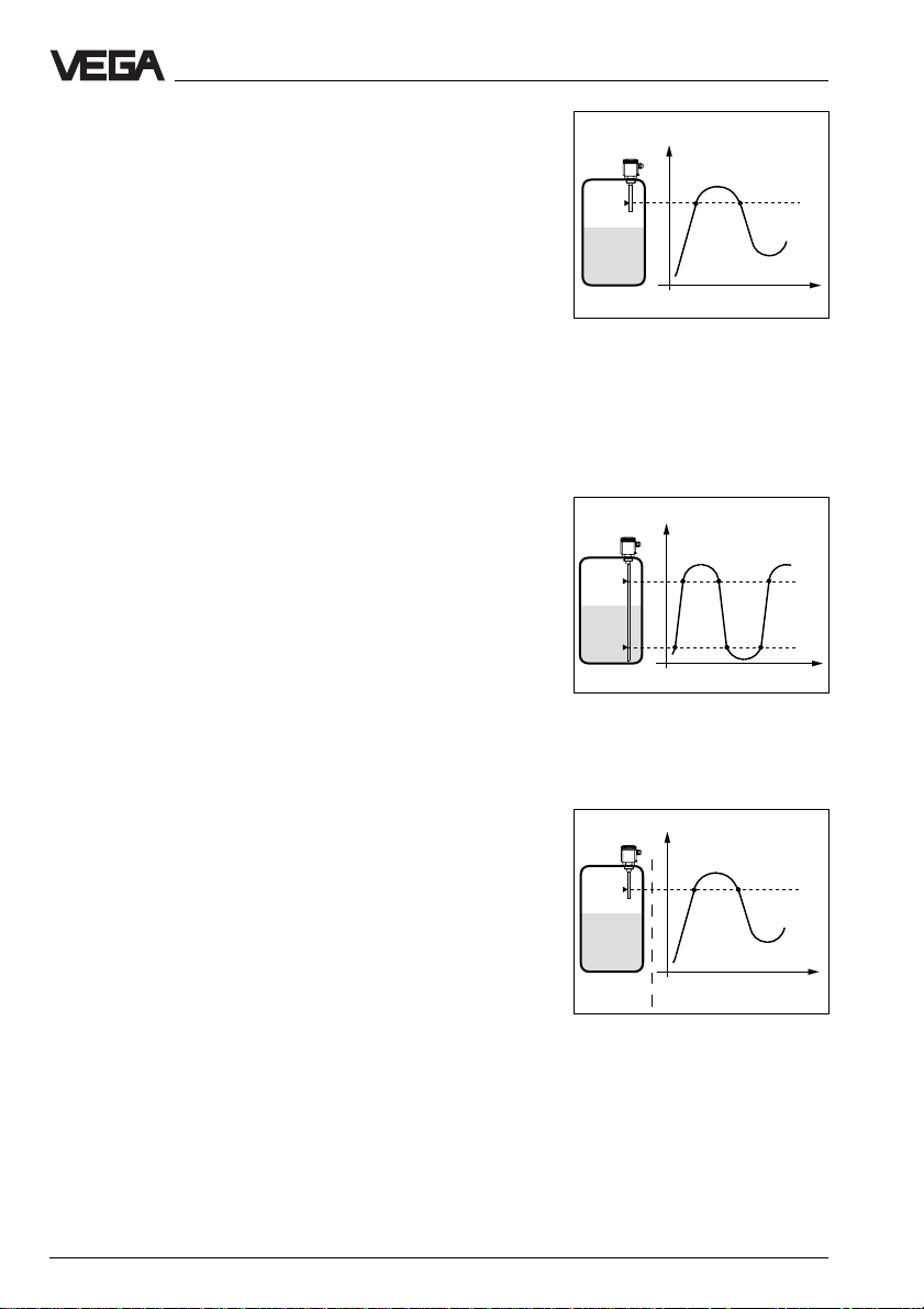
Adjustment example 1, mode A (overfill
protection)
- VEGATOR 620, 621
- single point control
- sensors: vertically mounted measuring
probes, hydrostatic pressure transmitters
or process pressure transmitters
Capacitive
meas. probes
Hydrostatic pressure
transmitters
Level/Pressure
Switching
point
Mode A
Mode B
Procedure
• Set the potentiometer (1) to 10.
• Fill the vessel up to the requested level or
pressure.
• Turn the potentiometer (1) very slowly
anticlockwise until the status indication (2)
changes, i.e. the status indication extinguishes.
• The signal conditioning instrument is now
ready for operation.
Please close with the transparent cover
(15).
Process pressure
transmitters
Rel.
t
12 13 14
12 13 14
Transistor
conductive
blocked
conductive
blocked
Adjustment example 2, mode B (dry
run protection)
- VEGATOR 620, 621
- single point control
- sensors: horizontally mounted capacitive
meas. probes or capacitive meas. probes
for adhesive products
Capacitive
meas. probes
Procedure
• Set the potentiometer (1) to 0.
• Fill the vessel up to 100 mm below the
electrode.
100 mm
• Turn the potentiometer (1) very slowly
clockwise until the status indication (2)
changes, i.e. lights in mode A, extinguishes
in mode B. Note the dial position of the
potentiometers (1).
• Continue filling the vessel until the measuring probe is completely covered. With
measuring probes for adhesive products,
the sensitive tip must be covered completely (standard 100 mm above the electrode). The status indication (2) changes
due to the additional filling.
100 mm
VEGATOR 620 … 622 15
Page 16

Setup
• Turn the potentiometer (1) very slowly
clockwise until the status indication (2)
changes, i.e. lights in mode A, extinguishes
in mode B. Note the position of the potentiometer.
• Determine the average value and adjust it
on the potentiometer (1).
• The signal conditioning instrument is now
ready for operation.
Please close with the transparent cover
(15).
The relay and transistor output as well as the
status indication behave in mode A and B as
previously shown in „Adjustment example 1“,
see top left.
Adjustment example 3
- two VEGATOR 620
- as dual single point control (see „3.3
Connection plans, extension example“)
- vertically mounted capacitive measuring
probes
Level 2
2nd VEGATOR…
Level 1
1st VEGATOR…
Procedure
• Set the potentiometers (1) of the two signal
conditioning instruments to 10.
• Fill the vessel up to level 1.
• Turn the potentiometer (1) of the first VEGATOR … very slowly anticlockwise until
the status indication (2) changes, i.e. lights
in mode B, extinguishes in mode A.
• Now fill the vessel up to level 2.
• Now turn the potentiometer (1) of the second VEGATOR … very slowly anticlockwise
until the status indication (2) changes, i.e.
lights in mode B, extinguishes in mode A.
• The two signal conditioning instruments are
now ready for operation.
Please close each with the transparent
cover (15).
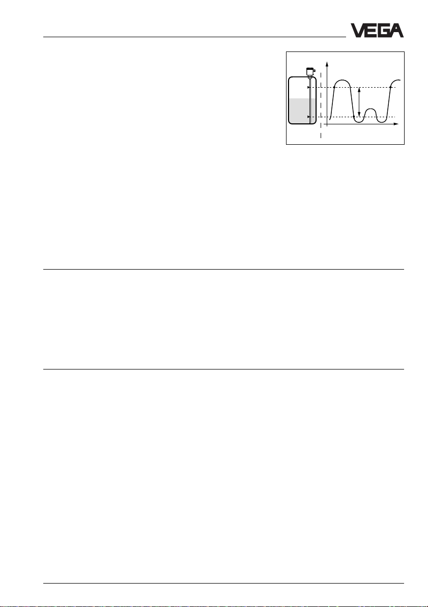
Adjustment example 4
- VEGATOR 622
- double point control
- sensors: vertically mounted capacitive
meas. probes or hydrostatic pressure
transmitters
Max. level
Min. level
Level/Pressure
Switching
points
2nd VEGATOR
Mode A
Mode B
1st VEGATOR
Mode A
Mode B
Level 2
Level 1
t
Rel.
12 13 14
12 13 14
12 13 14
12 13 14
Transistor
conductive
blocked
conductive
blocked
conductive
blocked
conductive
blocked
Level/Pressure
Switching
points
Mode A
Mode B
Max. level
Min. level
Rel.
t
12 13 14
12 13 14
Transistor
conductive
blocked
conductive
blocked
16 VEGATOR 620 … 622
Page 17

Setup / Diagnostics
Procedure
• Set both potentiometers (9 and 10) to 0.
• Fill the vessel to min. level.
• Turn the min. potentiometer (10) very
slowly clockwise until the status indication
(2) changes, i.e. lights in mode A, extinguishes in mode B.
• Now turn the potentiometer (9) to 10.
• Continue filling the vessel to max. level, the
status indication (2) remains unchanged.
• Turn the max. potentiometer (9) very slowly
anticlockwise until the status indication (2)
changes, i.e. extinguishes in mode A, lights
in mode B.
• The signal conditioning instrument is now
ready for operation.
Please close with the transparent cover
(15).
Note:
VEGATOR 622 can also be used for single
point control. The max. potentiometer must
be set to 0, the min. potentiometer then acts
as single point adjustment.
5 Diagnostics
5.1 Maintenance
The instrument is maintenance free.
5.2 Repair
Repairs require accessing internal parts of
the instrument to correct an instrument defect. For safety and warranty reasons, repair
must only be carried out by qualified VEGA
personnel.
In case of a defect, please return respective
instrument with a short description of the flaw
to our repair department.
Failures are short-term malfunctions caused
by wrong adjustment or defects in the sensor
or in the connection cables.
Failures, their possible causes and their
rectification are listed under „5.3 Failure rectification“.
VEGATOR 620 … 622 17
Page 18

Diagnostics
5.3 Failure rectification
Failu re Rectification / Measure
Instrument is dead/
Green operating
lamp extinguishes Check the voltage supply and the mains connections as described
VEGATOR 620 Check the sensor inputs for the following failures:
functions incorrectly - short-circuit on the input
or not at all - sensor not connected correctly or polarity-reversed
Red failure LED
of VEGATOR 621 Check if the sensor is connected correctly.
or 622 lights - failures in the sensor, effecting a current change to below 2 mA or
under „Connection instructions“. If the instrument still does not function,
please call our service department.
- sensor line interrupted
- supply voltage too low
above 23 mA, generate a fault signal on VEGATOR.
15 … 18 V
(24 V with VEGATOR 620)
V
VEGATOR
12 43
Measure the current in
the connection cable
to the sensor.
4 … 20 mA
+
-
mA
For Ex systems, make sure that the Ex protection is not degraded
by the measuring instruments.
a. Current value < 2 mA
- Check the supply voltage on the connection cable to the sensor. The
voltage should be at least 17 V.
Should a value below 17 V be measured, it indicates a defect in the
signal conditioning instrument. In this case, return the instrument for
repair to VEGA.
- If at least 17 V are available, separate the signal conditioning instrument from the connection cable and connect to the sensor input of
the signal conditioning instrument a resistor of 2.2 kOhm.
If the failure lamp continues to light, the signal conditioning instrument
is defective. In such a case, return the instrument for repair to VEGA.
- Should the failure lamp extinguish, reconnect the signal conditioning
instrument. Separate the sensor from the connection cable and connect a resistor of 2.2 kOhm in its place.
- Should the failure lamp continue to light, there is probably an interruption of the connection line. Check the connection cable to the
sensor.
- If the failure lamp extinguishes, the sensor is defective. Check the
connected sensor.
18 VEGATOR 620 … 622
Page 19

Diagnostics
Failu re Rectification / Measure
VEGATOR 620
functions incorrectly
or not at all
Red failure LED
of VEGATOR 621
or 622 lights b.Current value > 22 mA
- Check all connections and the connection cable to the sensor.
- Should the red failure lamp continue to light, separate the sensor
from the connection cable and connect a resistor of 2.2 kOhm in its
place.
If the failure lamp extinguishes, the sensor is defective. Check the
connected sensor.
- Should the failure lamp continue to light, reconnect the sensor. Separate the signal conditioning instrument from the connection cable and
connect a resistor of 2.2 kOhm to its sensor input.
- Should the failure lamp continue to light, the signal conditioning instrument is defective. In such a case, return the instrument for repair to
VEGA.
- If the failure lamp extinguishes, there is probably a short circuit in the
connection line. Check the connection cable to the sensor.
Note:
A flawlessly operating VEGATOR… has the following switching point values:
Potentiometer position Sensor current
0 approx. 4 mA
5 approx. 12.5 mA
10 approx. 21 mA
VEGATOR 620 … 622 19
Page 20

VEGA Grieshaber KG
Am Hohenstein 113
77761 Schiltach/Germany
Phone +49 (0) 7836 50-0
Fax +49 (0) 7836 50-201
E-Mail info@de.vega.com
www.vega.com
ISO 9001
The statements on types, application, use and operating conditions of the sensors and processing systems correspond to
the latest information at the time of printing.
Technical data subject to alterations
2.19 950 / July 2001
 Loading...