

Page 1
Operating Instructions
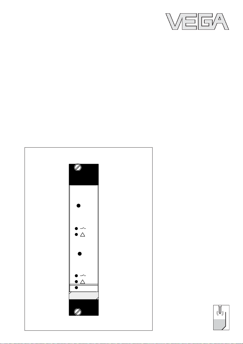
VEGATOR 537 Ex
TEST
1
TEST
2
on
VEGATOR
537 Ex
Page 2

Contents
Safety information ........................................................................ 2
Attention Ex area .......................................................................... 2
1 Product description .................................................................. 3
1.1 Configuration ........................................................................ 3
1.2 Technical data ....................................................................... 3
1.3 Dimensions ........................................................................... 5
2 Mounting ..................................................................................... 6
3 Electrical connection ................................................................ 8
3.1 Connection plan ................................................................... 9
4 Setup .......................................................................................... 10
5 Diagnosis .................................................................................. 14
5.1 Recurring test acc. to WHG .............................................. 14
5.2 Failure rectification ............................................................. 14
Safety information
Safety information
Please read this manual carefully, and also take
note of country-specific installation standards
(e.g. the VDE regulations in Germany) as well
as all prevailing safety regulations and accident prevention rules.
For safety and warranty reasons, any internal
work on the instruments, apart from that involved in normal installation and electrical connection, must be carried out only by qualified
VEGA personnel.
2 VEGATOR 537 Ex
Attention Ex area
Please note the attached safety instructions
containing important information on installation
and operation in Ex areas.
These safety instructions are part of the operating instructions manual and come with the Ex
approved instruments.
23465-EN-030723
Page 3

Product description
1 Product description
1.1 Configuration
A measuring system with signal conditioning
instrument consists of:
- a VEGAVIB series 50 with oscillator
VIB E50 Z (Ex)
- a VEGATOR 537 Ex signal conditioning
instrument
- external devices operated by VEGATOR
or
- a VEGASWING series 60 or 80A with oscillator SW E60ZEx, SW E82Z or SW E82ZEx
- a VEGATOR 537 Ex signal conditioning
instrument
- external devices operated by VEGATOR
1.2 Technical data
General
Series module unit for carrier BGT 596 Ex
Dimensions W = 25.4 mm (5 TE), H = 128.4 mm, D = 162 mm
Weight approx. 180 g
Test key (per channel) for function test
Ambient conditions
Ambient temperature -20°C … +60°C
Storage and transport temperature -40°C … +70°C
Power supply
Operating voltage 20 … 53 V AC, 20 … 72 V DC
Power consumption max. 3 W
Electrical connection multiple plug DIN 41 612,
Electrical protective measures
Protection class II
Overvoltage category II
Protection
- mounted into housing type 505 Ex IP 30
Protection
(mounted into carrier
BGT 596 Ex with Ex module)
- front side (completely equipped) IP 30
- upper and lower side IP 20
- wiring side IP 00
23465-EN-030723
VEGATOR 537 Ex 3
series F (d, b, z) 33-pole
Page 4
Product description
Inputs
Number 2 sensor inputs
Data transmission analogue
Switching threshold 12 mA
Current limitation 24 mA (permanently short-circuit proof)
Sensor supply voltage 15 … 18 V DC
Connection cable 2-wire
Resistance per conductor max. 35 Ω
Integration time 0.2 … 20 s, directionally switchable
(adjustment via DIL switch)
Relay output
Number, function 2 switching relays (spdt), 1 fail safe relay
Mode A/B-mode
A - max. detection or overfill protection
B - min. detection or dry run protection
Contact 1 spdt each
Contact material AgCdO and Au plated
Turn-on voltage min. 10 mV
max. 250 V AC, 250 V DC
Switching current min. 10 µA
max. 3 A AC, 1 A DC
Breaking capacitance max. 500 VA AC, 54 W DC
Transistor output
Number, function 3, synchronously switch with relays
Galvanic isolation floating
Max. values UB max. 36 V DC
IB max. 60 mA
Transistor voltage loss UCE min. - 1.5 V at IB 60 mA
Blocking current < 10 µA
Indicating elements
LED in front plate
- green on operating voltage on
- yellow switching point control
- red fault signal
Explosion protection
Certificate conformity certificate
TÜV 01 ATEX 1780
Classification mark ATEX II 1 GD EEx ia IIC/IIB
Please note the attached saftey instructions containing important information on installation
and operation in Ex areas.
These safety instructions are part of the operating instructions manual and come with the
Ex approved instrument.
4 VEGATOR 537 Ex
23465-EN-030723
Page 5
Product description
Electrical connection
Mounted into
- carrier BGT 596 Ex 33-pole multipoint connector, series F (d, b, z)
- in housing type 505 Ex screw terminal, max. for 1.5 mm
with coding holes
2
CE conformity
VEGATOR 537 Ex signal conditioning instruments meet the protective regulations of EMC
(89/336/EWG) and NSR (73/23/EWG). Conformity has been judged acc. to the following
standards:
EMC Emission EN 50 081 - 1: 1993
Susceptibility EN 50 082 - 2: 1995
NSR EN 61 010 - 1: 1993
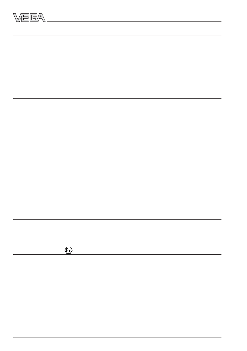
1.3 Dimensions
Circuit board 100 x 160 x 1.5
European size
Multiple plug
100
5 TE
128,4 (3 HE)
on
5,5
9
15
23465-EN-030723
VEGATOR 537 Ex 5
3
162
25,4
Page 6

2 Mounting
Mounting
VEGATOR can be either installed with a module into a carrier BGT 596 or a single housing
type 505.
Module (33)
for VEGATOR 537
Multipoint connector DIN 41 612, series F,
33-pole (d, b, z) with coded pin and material
for mounting into carrier BGT 596.
Module Ex (33 Ex)
for VEGATOR 537 Ex
Multipoint connector DIN 41 612, series F,
33-pole (d, b, z) with coded pin and material
for mounting into carrier BGT 596 Ex.
Single housing
Plastic housing type 505 for single mounting
of signal conditioning instruments with instrument width 5 TE (25.4 mm).
Mounting carrier
Mount the respective module (standard or Ex
version) on the carrier BGT 596. Wire the
multipoint connector acc. to the wiring diagrams on the following pages.
Mounting single housing
You can either screw the socket directly onto
the mounting plate or plug it onto the carrying
rail (TS 35 x 7.5 acc. to EN 50 022 or TS 32
acc. to EN 50 035). Connect the terminals to
the basic board acc. to the wiring diagram on
the following pages. For further mounting
information, see operating instructions of the
housing.
Transparent cover
The front panel of VEGATOR can be fitted
with a sealable transparent cover to prevent
unauthorized or inadvertent use. The cover is
provided with the instrument.
The multipoint connector is available in the
following versions:
- Wire-Wrap standard connection
1.0 x 1.0 mm
- plug connection 2.8 x 0.8 mm
- Termi-Point standard connection
1.6 x 0.8 mm
- soldering connection
- screw terminals 2 x 0.5 mm
2
For further information concerning mounting,
see operating instructions of the carrier.
6 VEGATOR 537 Ex
23465-EN-030723
Page 7

Mounting
Coding
The multipoint connector of the instrument is
provided with one or more coding holes to
prevent incorrect module insertion.
A fixed coded pin on the Ex module ensures
that only Ex instruments can be inserted.
Two additional coded pins are enclosed with
the module to prevent incorrect insertion of
other instruments. Insert the attached coded
keys into the holes on the multipoint connector. The coded keys must be plugged into
the following positions:
Instrument Ex coding
coding
VEGATOR 537 a19 / c7 ––
VEGATOR 537 Ex a19 / c7 c23
z b d
a c
o 1 o
o 3 o
o 5 o
o 7 o
o 9 o
o11o
o13o
o15o
o17o
VEGATOR 537
o19o
o21o
o23o
o25o
o27o
o29o
o31o
Fig. 2.8 Module 33 (Ex)
c7
c23
VEGATOR
Ex coding
Ex version
Ex separating chamber
An Ex separating chamber must be mounted
to the connections of VEGATOR to ensure
sufficient "air and creep distances". Feed the
cables through the Ex separating chamber
and connect them. Fasten the Ex separating
chamber with the lower retaining screw. Note
the operating instructions of the carrier BGT
596.
Mounting in carriers
If you are mounting a VEGATOR with Ex
approval in an assembly carrier, you must
use a VEGA-Ex module. Leave a distance of
min. 10 mm (2 TE) to modules of other manufacturers. If VEGATOR is to be mounted in
the carrier at the extreme left position, a blind
cover with min. 20 mm (4 TE) must be
mounted to the left of the module.
2
on
VEGATOR
Blind cover
Protection for Ex applications
For Ex applications, protection IP 20 must be
maintained. To do this, cover gaps and
empty slots with blind covers.
Fig. 2.9
23465-EN-030723
VEGATOR 537 Ex 7
Page 8

3 Electrical connection
Electrical connection
Danger
Switch off the power supply before starting
connection work. Connect mains voltage acc.
to the following connection diagram.
When connecting to supply voltage or reconnecting the sensor, the instrument is subjected to a function test. See also "5.1
Recurring test acc. to WHG".
If only one channel is used on VEGATOR
537 Ex signal conditioning instrument, connect a resistor of 1 kΩ (0.5 W) to the unused
connection pins of the second channel. The
resistor prevents a fault signal, caused by a
missing sensor, from being triggered.
A transistor output operating in parallel is
available for each relay output.
Note
If very strong electromagnetic interference is
expected, we recommend the use of
screened cable. The screen of the cable
must only be earthed at one end. Carry out
the earthing on the sensor side.
The following connection plan shows the
currentless condition.
Module with multipoint connector acc. to
DIN 41 612 for carrier (rear view)
d b z
2
4
6
8
10
12
14
16
18
20
22
24
2 3
26
28
30
32
1 kΩ resistance with
unused channel
Sensor 1
2 3
1
Sensor
Channel 2
Ex separating chamber
Sensor
Channel 1
Sensor 1
1
8 VEGATOR 537 Ex
23465-EN-030723
Page 9

Electrical connection
3.1 Connection plan
All contacts in zero current condition
d b z
+-
Supply
voltage
L1 (+)
N (-)
2
6
Fail safe relay
Fail safe transistor
Level transistor 1
+
-
Sensor 1
10
12
+
16
-
18
+
20
-
22
24
28
+
30
-
32
+
-
+
-
Level relay 1
Level relay 2
Level transistor 2
+
-
Sensor 2
23465-EN-030723
VEGATOR 537 Ex 9
Page 10

4 Setup
Indicating and adjustment elements
Setup
12
VEGATOR 537 Ex
off
1
123456
on
off
2
123456
on
15 10
1 Connection plan
2 Lockable fixing screw
3 Test 1) channel 1
4 LED level relay 1
5 LED-fault signal channel 1
6 Test key 1) channel 2
7 LED level relay 2
onoff
12
8 LED fault signal channel 2
9 LED supply voltage
10 Fixing screw
11 Multipoint connector
12 Change-over switch min./max. control
13 DIL switch block for channel 1
14 DIL switch block for channel 2
15 Transparent cover
3
TEST
4
5
6
1
TEST
7
VEGATOR
2
on
537
8
9
111314
1)
Recurring test acc. to WHG
In accordance with the type approval acc. to WHG (Z-65.11-154, Z-65.11-285), the recurring test acc. to
WHG can be carried out by pressing the test key on the VEGATOR signal conditioning instrument. It is
neither necessary to remove the sensor nor trigger a response by filling the vessels. This applies to
VEGASWING 61Ex, 63Ex, 81AEx and 83AEx with two-wire oscillator SW 60ZEx and SW E82ZEx.
10 VEGATOR 537 Ex
23465-EN-030723
Page 11

Setup
Control lamps
LEDs in the front plate indicate the operating
status, switching condition and faults.
Green
- operating control lamp (9)
- mains voltage On, instrument in operation.
Red
- signal lamps (5 and 8)
- failure of the respective sensor circuit
through sensor failure or line defect.
- when the fail safe relay deenergises, the
red control lamp lights.
Yellow
- relay control lamp (4 and 7)
- the yellow control lamps react according to
the adjusted mode (A/B).
- the relay control lamps indicate the energised condition of the relay.
- an unlit control lamp thus means that the
relay is deenergised.
DIL switch block and potentiometer
Mode and integration time
On every output of the circuit board of
VEGATOR there is one DIL switch block (13
and 14) with 6 switches each. The individual
switches are assigned as follows:
1 A/B mode
A - max. detection or overfill protection
B - min. detection or dry run protection
2 Switch off delay (za)
3 Switch on delay (ze)
4 Integration time 2 s
5 Integration time 6 s
6 Integration time 12 s
With switches 2 and 3 you can adjust independently the switch off and/or the switch on
delay. The switch on or off delay relates to the
switching status of the relay and transistor
outputs.
In the illustrated example, mode A (max.
detection or overfill protection) is selected
(switch 1). The switch on delay is activated
(switch 3) and the integration time is set to 8
seconds (switch 4, 5 and 6).
1 A/B mode
2 Switch off delay
3 Switch on delay
4 Integration time +2 s
5 Integration time +6 s
6 Integration time +12 s
B- -
123456
A
sec
0
00
zaze26
sec
12
With switches 4, 5 and 6 the integration time
can be adjusted respectively. The time intervals of the activated time switches are
summed. In case the switch on (ze) and
switch off delay (za) are activated together,
the adjusted time is valid for both types of
delay.
Switch123456
Time
0,2 s A/B00000
0,5 s A/B 0 0 0
2 s A/B 200
6 s A/B 060
8 s A/B 260
12 s A/B 0 0 12
14 s A/B 2 0 12
18 s A/B 0 6 12
20 s A/B 2 6 12
Either switch 2 or switch 3
to "–". The times are valid
for the respectively
adjusted delay mode.
With switch 1, the mode (A - overfill protection
or B - dry run protection) can be adjusted.
When used as part of a certified overfill protection system, switch 1 must be set to position A.
23465-EN-030723
VEGATOR 537 Ex 11
Page 12

Setup
Min./Max. mode
The min./max. switch (12) is used for linking
both sensor inputs to one common min./max.
signal. With it, you can create a pump controls system.
erer
minalsminals
er
minals
erer
minalsminals
Switch
on
off
• Connect the sensor of the upper switching
point to sensor input 1, the sensor of the
lower switching point to sensor input 2.
• Set the A/B switch (switch 1) on the DIL
switches (13 and 14) of both sensor channels to position A (overfill protection/max.
detection).
• Depending on whether you want to connect
a filling or emptying pump, you must connect the pump accordingly to output relay
1.
ModeMode
Mode
ModeMode
TT
T
TT
Filling pump d10, b10
Emptying pump b10, z10
Level
Output relay 2 cannot be used for pump
control. It has the following function:
Sensor uncovered – relay 2 energised,
Sensor covered – relay 2 deenergised.
Double point control
Measuring system for detection of two levels
(alternating function), e.g. pump control.
Mount the vibrating level switch at the respective switching points
- at the respective level,
- as tube version, mounted with adjustable
locking screw connection,
- with tube extension of respective length
- suitable signal conditioning instruments (in
conjunction with oscillator SW E60Z, SW
E82Z/VIB E50Z) VEGATOR 537 Ex.
Level
off
on
off
1 Relay energised
2 Relay deenergised
2
Time
Fault monitoring
1
Time
Relay 1Relay 1
Relay 1
Relay 1Relay 1
Sensor 1Sensor 1
Sensor 1
Sensor 1Sensor 1
(top)(top)
(top)
(top)(top)
1
Sensor 2Sensor 2
Sensor 2
Sensor 2Sensor 2
(bottom)(bottom)
(bottom)
(bottom)(bottom)
uncovered uncovered energised
covered covered deenergised
12 VEGATOR 537 Ex
The measuring system is monitored continuously. The following criteria are checked:
- line break or short circuit in two-wire cable
- interruption of the connection cable to the
piezoelectric elements
- corrosion or damage of the tuning fork
(vibrating rod)
- break of the tuning fork (vibrating rod)
- loss of vibration
- vibrating frequency too low
- corrosive medium in the sensor (penetrating from vessel interior)
23465-EN-030723
Page 13

Setup
Test key
In systems with two-wire oscillators
(VIB E50 Z (Ex), SW E60ZEx, SW E82ZEx) a
function test can be carried out.
VEGATOR 536 Ex signal conditioning instrument is equipped with an integrated test key.
The test key is set lowered into the front plate
of the signal conditioning instruments. Press
the test key with a suitable object (screwdriver, pen etc.). If VEGASWING is connected to a VEGALOG processing system or
a PLC, you have to interrupt the connection
cable to the sensor. By pushing the test key,
the measuring system is checked according
to the following criteria:
- switching function of the switching outputs
- switching function of the fault signal outputs
- potential separation of the outputs
- signal processing of the signal conditioning
instrument.
After pressing the test key, the functionality of
the entire measuring system is checked.
During the test, the following operating conditions are simulated:
- fault signal
- empty signal (only with VEGASWING)
- full signal.
Check if all three switching conditions occur
in the correct sequence and in the stated
duration. If this is not the case, there is a
failure in the measuring system (see "5.2
Failure rectification"). Please note that the
connected instruments are activated during
the function test, which allows you to check
the functionality of all components of the
measuring system.
Due to this fault monitoring, the combination
of the following instruments corresponds to
requirement classes 1 to 3 (AK 3) acc. to DIN
19 251. AK 3 means that the system is fail
safe.
- VEGASWING 61Ex, 63Ex, 81AEx, 83AEx
- SW E60ZEx, SW E82 Z Ex oscillator
- VEGATOR 536 Ex, 537 Ex, 636 Ex signal
conditioning instrument
VEGAVIB is also subjected to the function
test, but it has no approval acc. to WHG and
AK 3 acc. to DIN 19 251.
Test sequence A mode B mode
1 Simulation of a fault signal (after release of the key approx. 3 s)
1)
Level relay deenergised
Fail safe relay deenergised
2 Simulation of an empty signal (approx. 1.5 s) only with VEGASWING
Level relay energised
Fail safe relay energised
3 Simulation of a full signal (approx. 1.5 s)
Level relay deenergised
Fail safe relay energised
4 Return to the current operating status (covered/uncovered)
1)
The instrument remains at failure as long as the test key is pushed.
23465-EN-030723
VEGATOR 537 Ex 13
Page 14

5 Diagnosis
Diagnosis
5.1 Recurring test acc. to WHG
The implementation of the recurring test acc.
to WHG is regulated in the general type approval no. Z-65.11-154, Z-65.11-285 (see
item 8 of the certificate).
Please give attention to these higher-priority
approvals when VEGASWING 81A and 83A
are used as part of an overfill protection
system acc. to WHG.
VEGASWING 61Ex, 63Ex, 81AEx and 83AEx
with signal conditioning instruments
VEGATOR 536 Ex, 537 Ex, 636 Ex meet in
mode A (overfill protection the fail safe requirements acc. to AK 3.
Recurring test acc. to WHG
In accordance with the type approval acc. to
WHG (no. Z-65.11-154, Z-65.11-285) the
recurring test acc. to WHG can be carried
out by pushing the test key on the VEGATOR
536 Ex, 537 Ex, 636 Ex signal conditioning
instrument. The sensor must neither be removed, nor must a response be triggered by
filling the vessel. This applies to
VEGASWING 61Ex, 63Ex, 81A Ex and
83A Ex with SW E60ZEx, SW E82ZEx twowire oscillator.
The implementation and the switching sequence of the function test is stated under
"Test key" and the accompanying table in the
operating instructions of the respective
VEGATOR signal conditioning instrument.
5.2 Failure rectification
Failure Corrective measure, failure rectification
The red fault signal Check the sensor inputs for the following causes of failure:
LED of the signal - short-circuit on the input
conditioning instru- - incorrect connection of the sensor
ment lights - sensor cable interrupted
- sensor voltage too low
Check if the sensor is connected correctly.
- failures in the sensor, effecting a current change to below 2 mA or
above 23 mA, will cause a fault signal on the signal conditioning instrument.
Measure the current on the connection cable to the sensor.
The terminal voltage of the sensor in normal condition is at least 12 V.
4 … 20 mA 12 … 20 V
mA
+
–
Sensor
V
28
+
+
30
–
–
32
VEGATOR
series 500
In Ex systems, make sure that the Ex protection is not degraded
by the measuring instruments.
14 VEGATOR 537 Ex
23465-EN-030723
Page 15

Diagnosis
a. Current value < 2 mA
- Check the voltage supply on the connection cable to the sensor. The
voltage should be approx. 17 … 20 V.
If you measure a value below 17 V, it indicates a defect in the signal
conditioning instrument. In this case, send the instrument for repair to
VEGA.
- If the red fault signal lamp continues to light, separate the connection
cable from the signal conditioning instrument and connect a resistance of 1 kΩ to the sensor inputs of the signal conditioning instrument.
If the fault signal lamp continues to light, the signal conditioning in-
strument is defective. In this case, send the instrument for repair to
VEGA.
- If the fault signal lamp extinguishes, reconnect the signal conditioning
instrument. Separate the sensor from the connection cable and connect instead a resistance of 1 kOhm.
- If the fault signal lamp continues to light, the connection cable is probably interrupted. Check the connection cable to the sensor.
- If the fault signal lamp extinguishes, the sensor is defective. Check
the connected sensor.
b.Current value > 22 mA
- Check all connections and the connection cable to the sensor.
- If the red fault signal lamp continues to light, separate the sensor
from the connection cable and connect instead a resistance of 1 kΩ.
If the fault signal lamp extinguishes, the sensor is defective. Check
the connected sensor.
- If the fault signal lamp continues to light, reconnect the sensor. Separate the signal conditioning instrument from the connection cable and
connect a resistance of 1 kΩ to the sensor input.
- If the fault signal lamp continues to light, the signal conditioning instrument is defective. In this case, send the instrument for repair to
VEGA.
- If the fault signal lamp extinguishes, there is probably a short-circuit
in the connection cable. Check the connection cable to the sensor.
Malfunction After pushing the test key, the switching status does not appear in
during function test the correct sequence or in the correct duration, e.g. no full signal is
triggered.
- Measure the line resistance
If the connecting line has acquired excessive resistance, you must
reduce its resistance to a normal level through appropriate measures. Check, e.g. the terminal and cable connections for corrosion.
23465-EN-030723
VEGATOR 537 Ex 15
Page 16

VEGA Grieshaber KG
Am Hohenstein 113
77761 Schiltach/Germany
Phone +49 (0) 7836 50-0
Fax +49 (0) 7836 50-201
E-Mail info@de.vega.com
www.vega.com
ISO 9001
All statements concerning scope of delivery, application, practical
use and operating conditions of the sensors and processing systems correspond to the latest information at the time of printing.
Technical data subject to alterations
23465-EN-030723
 Loading...