

Page 1
Operating Instructions
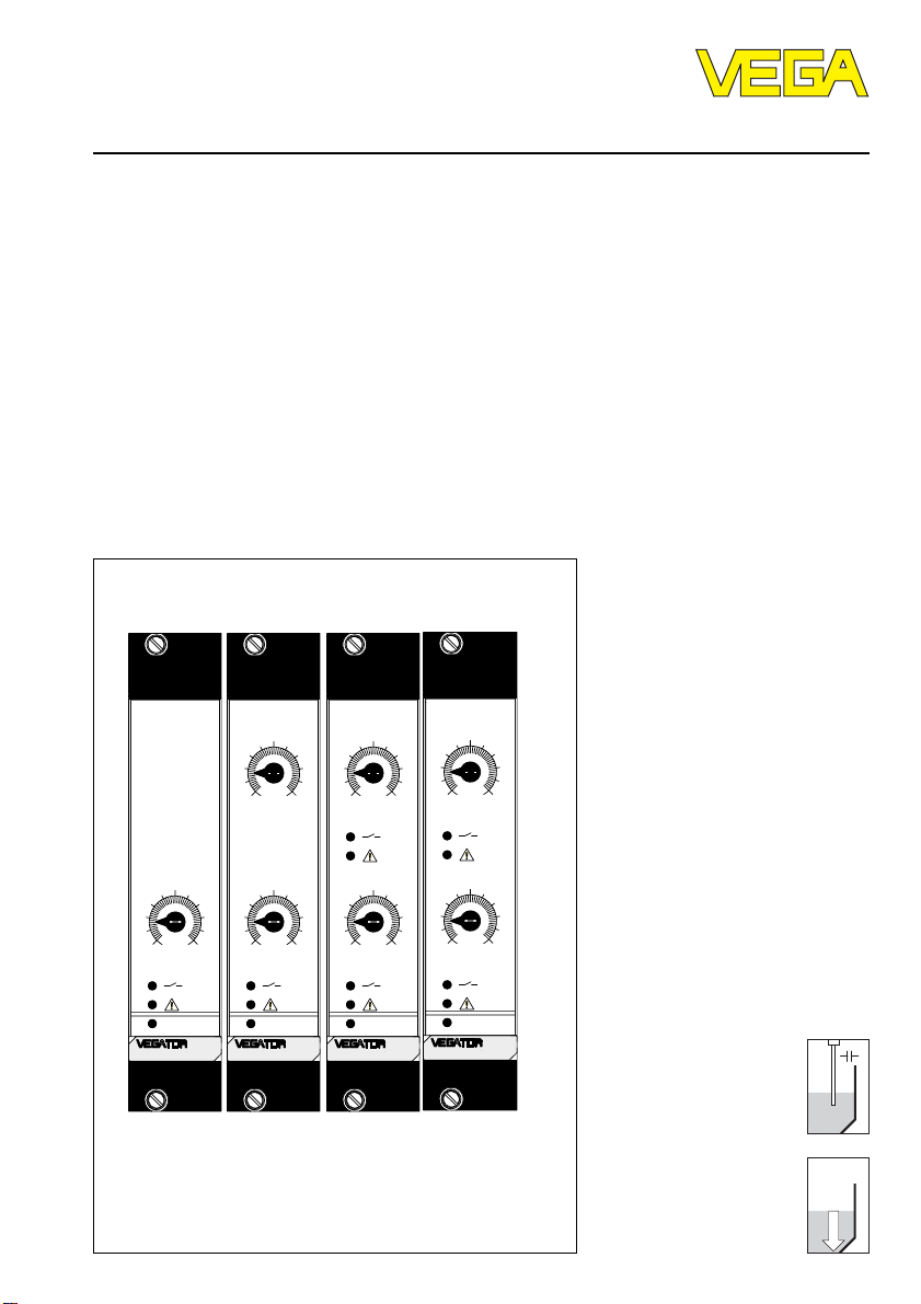
VEGATOR 521, 522, 523, 527
Level and Pressure
5
010
on
521
5
010
max
5
010
min
on
522
5
010
1
5
010
2
on
523
5
010
1
5
010
2
on
527
p
Page 2

Contents
Safety information ........................................................................ 2
Note Ex area ................................................................................ 2
1 Product description
1.1 Function and configuration .................................................. 3
1.2 Types and versions ............................................................. 3
1.3 Approvals ............................................................................. 3
1.5 Dimensions ........................................................................... 6
2 Mounting
2.1 Mounting instructions ........................................................... 7
3 Electrical connection
3.1 Connection instructions ....................................................... 9
3.2 Connection schematic ......................................................... 9
4Setup
4.1 Indicating and adjustment elements ................................ 11
4.2 Principle of operation ......................................................... 13
4.3 Switching point adjustment ............................................... 14
Contents
5 Diagnostics
5.1 Maintenance ....................................................................... 21
5.2 Repair.................................................................................. 21
5.3 Failure rectification ............................................................. 22
Safety information
Please read this manual carefully, and also take
note of country-specific installation standards
(e.g. the VDE regulations in Germany) as well
as all prevailing safety regulations and accident
prevention rules.
For safety and warranty reasons, any internal
work on the instruments, apart from that involved
in normal installation and electrical connection,
must be carried out only by qualified VEGA
personnel.
2 VEGATOR
Note Ex area
Please note the approval documents (yellow
binder), and especially the included safety
data sheet.
Page 3

Product description
1 Product description
1.1 Function and configuration
VEGATOR 521, 522, 523 and 527 level
switches are signal conditioning instruments
in European size (DIN 41 494) for level
detection. Typical applications are overfill
protection in vessels and dry run protection
or double point control of pumps. Depending
on the instrument type, up to 2 sensors with
analogue transmission of measured data can
be connected to the input. 2 relays (spdt)
and 2 floating transistors are available as
outputs. All instruments are equipped with a
fail-safe relay and transistor. The instruments
are provided with fault monitoring and
adjustable integration time.
All VEGATORs are available with Ex
approvals or as overfill protection systems
acc. to WHG and VbF.
Function
VEGATOR signal conditioning instruments
enable detection of min./max. levels. The
measured data of the sensor are converted
into a switching command, and connected
instruments can be switched on or switched
off. The integrated fault monitoring detects
short-circuit or break of the measuring cable
as well as selected failures from the
transmitter. The failure lamp lights and the
output relays and output transistors are
deenergised in case of failure.
1.2 T ypes and versions
VEGATOR 521 (Ex)
Signal conditioning instrument as level switch
for single point control. 1 sensor input for
capacitive electrodes or pressure
transmitters. 1 relay output (spdt) and 1
transistor output with fixed switching
hysteresis.
VEGATOR 522 (Ex)
Signal conditioning instrument as level switch
for one sensor for double point control. 1
sensor input for capacitive electrodes or
pressure transmitters. 1 relay output (spdt)
and 1 transistor output with adjustable
switching hysteresis.
VEGATOR 523 (Ex)
Signal conditioning instrument as level switch
for one sensor for dual single point control.
1 sensor input for capacitive electrodes or
pressure transmitters. 2 relay outputs (spdt)
and 2 transistor outputs with fixed switching
hysteresis.
VEGATOR 527 (Ex)
Signal conditioning instrument as level switch
for two sensors for single point control. 2
sensor inputs for capacitive electrodes or
pressure transmitters. 2 relay outputs (spdt)
and 2 transistor outputs with fixed switching
hysteresis.
In case of mains failure, the relays
deenergise.
Configuration
For configuration of a measuring system, a
VEGATOR and one or two sensors with
analogue measured data transmission, e.g. a
capacitive electrode or a pressure
transmitter are required.
VEGATOR 3
1.3 Approvals
VEGATOR is available with the following
approvals:
- explosion protection: respective instrument
with intrinsically safe circuit(s) [EEx ia] IIC
- overfill protection acc. to WHG applied for
For these applications, please note the relevant offical documents (test report, test
certificates, type approvals and conformity
certificates). These are supplied with the
respective instrument.
Page 4

Product description
1.4 Technical data
General
Version European size DIN 41 612
Dimensions W = 25.4 mm (5 TE); H = 128.4 mm; D = 162 mm
Weight approx. 180 g
Ambient temperature -20°C … +60°C
Storage and transport temperature -40°C … +70°C
Power supply
Operating voltage 20 … 53 V AC, 50/60 Hz or 20 … 72 V DC
Power consumption max. 4 VA
Electrical protective measures
Protection class II
Overvoltage class II
Protection
- mounted in carrier
BGT 596 with module IP 00
- front side completely equipped IP 30
- upper and lower side IP 20 (only Ex carrier)
- wiring side (rear) IP 00
- single housing IP 20
Inputs
Transmission analogue
Switching threshold adjustable 4 … 20 mA
Hysteresis (fixed / min.) 80 µA
Current limitation 24 mA (permanently short-circuit proof)
Connection cable to the sensor 2-wire
Sensor supply voltage approx. 15 … 18 V DC
Resistance per wire max. 35 Ω
Temperature error 0.05 %/10 K (relating to range)
Integration time 0.2 … 20 s
Relay output
Number of
- VEGATOR 521, 522 1 level relay
- VEGATOR 523, 527 2 level relay
Modes A/B-switch
Contact floating spdt
Contact material AgNi and Au plated
Turn-on voltage min. 10 mV
Switching current min. 10 µA
Breaking capacitance max. 500 VA AC, 54 W DC
4 VEGATOR
1 fail-safe relay
1 fail-safe relay
A - max. detection or overfill protection
B - min. detection or dry run protection
max. 250 V AC/DC
max. 3 A AC, 1 A DC
Page 5

Product description
Transistor ouput
Number of
- VEGATOR 521, 522 2 (synchronous switching with relays)
- VEGATOR 523, 527 3 (synchronous switching with relays)
Galvanic separation floating
Operating voltage max. 36 V DC
Operating current max. 60 mA
Transistor voltage loss U
- 1.5 V
CE
Approvals
VEGATOR 521 Ex, 522 Ex, 523 Ex, 527 Ex
with input in classification
Intrinsic safety EEx ia IIC, EEx ia IIB
EEx ib IIC, EEx ib IIB
Max. values U
= 20 V
O
IK = 126 mA
P = 626 mW
Characteristics linear
EEx ia IIC EEx ia IIB EEx ib IIC EEx ib IIB
Max. permissible external inductance (mH) 0.5 1 1.5 2 2 9
Max. permissible external capacitance (nF) 97 78 68 486 200 1000
The intrinsically safe circuits are reliably (galvanically) separated from the non-intrinsically
safe circuits up to a peak value of the nominal voltage of 375 V.
On instruments with 2 channels (VEGATOR 527 Ex) the intrinsically safe circuits are reliably
separated.
CE conformity
VEGATOR 521 Ex, 522 Ex, 523 Ex and 527 Ex signal conditioning instruments meet the
protective regulations of EMC (89/336/EW) and NSR (73/23/EWG). Conformity has been
judged acc. to the following standards:
EMC Emission EN 50 081 - 1: 1993
Susceptibility EN 50 082 - 2: 1995
NSR EN 61 010 - 1: 1993
VEGATOR 5
Page 6
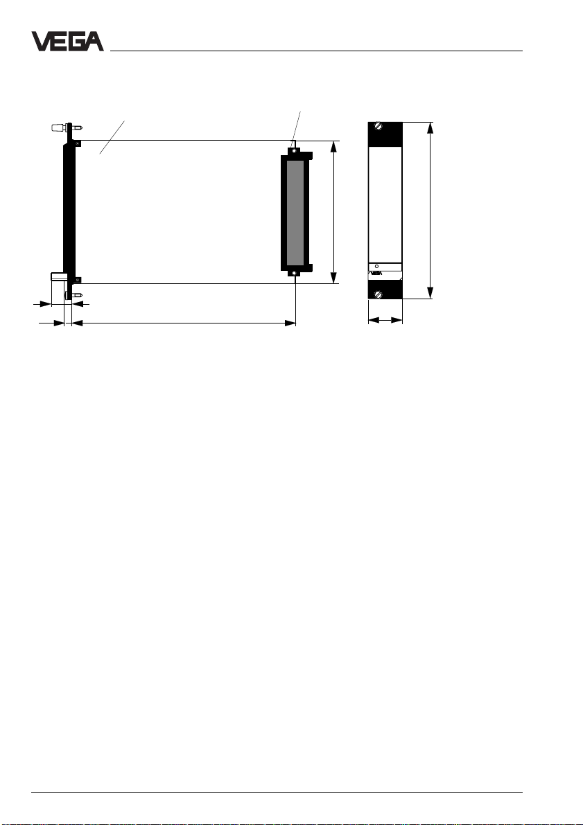
1.5 Dimensions
Circuit board 100 x 160 x 1.5
European size
Multiple plug
Product description
5 TE
9
5,5
162
100
128,4
on
25,4
6 VEGATOR
Page 7
Mounting
2 Mounting
2.1 Mounting instructions
VEGATOR can be mounted either in a card
slot in a carrier BGT 596 or in a single
housing type 505.
Card slot
Multipoint connector DIN 41 612, series F, 33pole (d, b, z) with coded pin and mounting
material for mounting in carrier BGT 596.
Card slot Ex
Multipoint connector DIN 41 612, series F, 33pole (d, b, z) with coded pins, Ex separating
chamber and mounting material for mounting
in carrier BGT 596 Ex.M.
Single housing
Plastic housing type 505 for individual
mounting of signal conditioning instruments
with instrument width 5 TE (25.4 mm).
Mounting carrier
Mount the respective module (standard or Ex
version) on your carrier BGT 596. Wire the
connections of the multipoint connector
according to the connection schematic on the
following page.
The multipoint connector is available as
follows:
- Wire-Wrap standard connection
1.0 x 1.0 mm
- Plug connection 2.8 x 0.8 mm
- Termi-Point standard connection
1.6 x 0.8 mm
- Soldering connection
- Screw terminals 2 x 0.5 mm
For further information on mounting, use the
operating instructions of the carrier.
2
Mounting single housing
The socket can be either screwed directly to
the mounting plate or plugged to a carrier rail
(TS 35 x 7.5 acc. to EN 50 022 or TS 32 acc.
to EN 50 035). Connect the terminals of the
basic plate according to the connection
schematic on the following page. For further
information on mounting, use the operating
instructions of the housing.
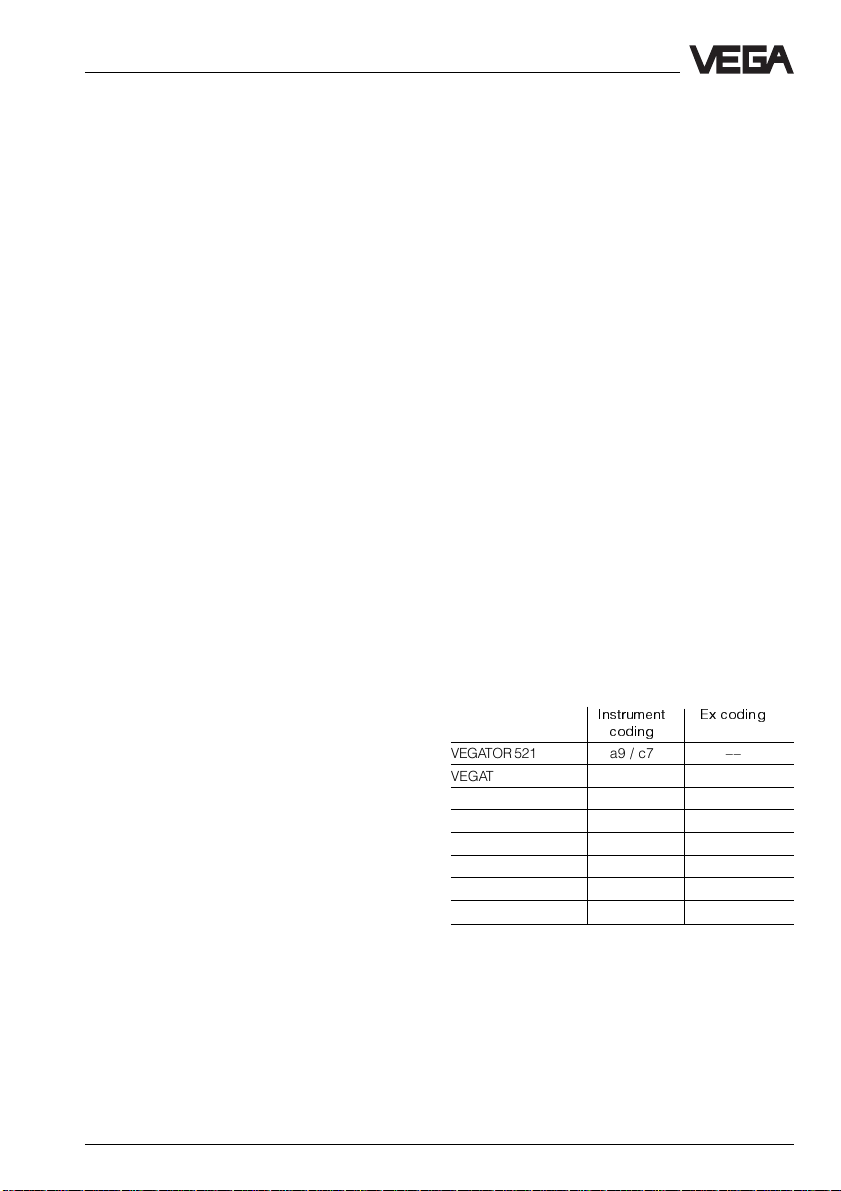
Coding
To prevent inadvertent swapping of the
various instruments, the multiple plug of the
instrument is provided with one or several
coding holes.
By means of a fixed coded pin on the Ex
module, it is ensured that only Ex instruments
can be inserted.
To prevent inadvertent swapping of the
various instruments, two additional coded
pins are included with the instrument. Insert
these coded pins into the predetermined
holes on the multipoint connector. The coded
pins must be inserted into the following
positions:
Instrument Ex coding
coding
VEGATOR 521 a9 / c7 ––
VEGATOR 521 Ex a9 / c7 c23
VEGATOR 522 a11 / c7 ––
VEGATOR 522 Ex a11 / c7 c23
VEGATOR 523 a13 / c7 ––
VEGATOR 523 Ex a13 / c7 c23
VEGATOR 527 a15 / c7 ––
VEGATOR 527 Ex a15 / c7 c23
VEGATOR 7
Page 8

Mounting
z b d
a c
o 1 o
o 3 o
o 5 o
VEGATOR 521 a9
VEGATOR 522 a11
VEGATOR 523 a13
VEGATOR 527 a15
o 7 o
o 9 o
o11o
o13o
o15o
o17o
o19o
o21o
o23o
o25o
o27o
o29o
o31o
c7
VEGATOR
c23
Ex-Codierung
Transparent cover
To protect the instrument against unauthorized or inadvertent use, the front plate of
VEGATOR can be provided with a lockable
transparent cover.
Ex version
Ex separating chamber
To ensure sufficient "air and creeping
distance", an Ex separating chamber must
be mounted to the connections of VEGATOR.
Lead the cables through the Ex separating
chamber and connect the cables. Fasten the
Ex separating chamber with the lower
holding screw. Note the operating
instructions of the carrier BGT 596 Ex.M.
Mounting in carriers
When mounting VEGATOR with Ex approval
in a carrier, a VEGA-Ex card slot must be
used. Keep a distance of at least 10 mm
(2 TE) to modules of other manufacturers.
When mounting VEGATOR to the complete
left position in the carrier, a blind cover of at
least 20 mm (4 TE) must be mounted in front
of the card slot of the instrument.
2
on
VEGATOR
Blind cover
Protection for Ex applications
For Ex applications, a protection of IP 20
must be maintained. Cover the gaps or free
card slots with blind covers from the front.
8 VEGATOR
Page 9

Electrical connection
3 Electrical connection
3.1 Connection instructions
The electrical connection should be carried
out according to the following connection
schematics. If only one channel is used on
the VEGATOR 527 signal conditioning
instruments, connect a resistor of 1 kΩ
(0.5 W) to the free connection pin of the second channel. The resistor prevents the
triggering of a fault signal caused by a missing sensor.
For each relay output, an additional paralleloperating transistor output is available.
Reset of alarm functions
For deactivation of a signalling device (horn,
diode etc.) in case of alarm (e.g. reaching the
max. permissible level), an additional key can
be connected to VEGATOR 521 or 522. This
key can deactivate a level alarm. In case of
failure (e.g. cable breakage), the alarm
cannot be deactivated.
If the key is connected, the fail-safe relay has
the same function as the level relay. However,
it is possible to reset the fail-safe relay by
pressing the key for reset of alarm functions.
If, for example, the max. level is reached and
an acoustic warning system is activated, this
system can be deactivated by pressing the
key for reset of alarm functions. The second
output (level relay) still signals the process
control that the max. level has been reached.
Note
If very strong electromagnetic interferences
are expected, screened cable is
recommended. The screening of the cable
should only be grounded on one sensor side
(e.g. capacitive electrode).
The following illustrations show the
currentless condition.
3.2 Connection schematic
VEGATOR 521 (Ex), 522 (Ex)
d b z
+-
Power
supply
Fail safe transistor
Level transistor
+
-
Sensor 1
L1 (+)
N (-)
2
6
10
12
+
16
-
18
+
20
-
22
24
28
30
32
Fail safe relay
Level relay
Key for reset of
alarm functions
(opener
function)
+
-
VEGATOR 9
Page 10

Electrical connection
VEGATOR 523 (Ex)
Power supply
Fail safe transistor
Level transistor 1
+
-
Sensor 1
L1 (+)
N (-)
2
6
10
12
16
18
20
22
24
28
30
32
VEGATOR 527 (Ex)
Power
supply
Fail safe transistor
Level transistor 1
L1 (+)
N (-)
2
6
10
12
16
18
20
22
24
d b z
+-
+
+
+
-
-
+
-
d b z
+-
+
+
+
-
-
Fail safe relay
Level relay 1
Level relay 2
Level transistor 2
Fail safe relay
Level relay 1
Level relay 2
Level transistor 2
Ex version
Please note the instructions in the attached
approval documents as well as the valid
installation regulations for connection of Ex
certified instruments.
Keep in mind that the Ex separating chamber
must be mounted on the multipoint connector.
Always lead the cables through the Ex
separating chamber. Check also the
operating instructions of the carrier BGT 596
Ex.M and the Ex instructions on page 8.
Wiring of the transistor outputs
(example VEGATOR 527 Ex)
VEGATOR 527 Ex PLC
+
I
B
U
CE
±
R
S
+
±
R
S
+
±
The resistor RS is used as short-circuit
protection
±
+
0.1
+
0.2
+
0.3
Example:
UB = 24 V, UCE - 1.5 V, IB = max. 60 mA
UB – U
R
= ––––––––– = ––––––––––––– = 375 Ω
S
I
B
CE
24 V – 1.5 V
60 mA
Sensor 1
28
+
+
+
-
30
-
-
32
+
-
Sensor 2
10 VEGATOR
Page 11

Setup
4 Setup
4.1 Indicating and adjustment elements
VEGATOR 521 VEGATOR 522 VEGATOR 523 VEGATOR 527
5
010
on
521
VEGATOR 527
B--
123456
zaze26
A
B--
123456
zaze26
A
5
010
5
010
on
sec
0
00
12
sec
sec
0
00
12
sec
5
max
min
522
010
1
5
010
2
on
523
5
010
1
5
010
2
on
527
12
3
5
4
010
5
6
on
off
on
off
7
8
9
1
5
010
2
on
527
16 13 1012
1 Connection plan
2 Lockable screw
3 Potentiometer as switching point
adjuster for max. (on VEGATOR 527
switching point adjuster for channel 1)
4 LED relay output 1
5 LED fault signal channel 1
6 Potentiometer as switching point
adjuster for min. (on VEGATOR 527
switching point adjuster for channel 2)
7 LED relay output 2
8 LED fault signal channel 2
9 LED power supply
10 Fixing screw
11 Multiple plug
111415
12 Min./Max. switch (VEGATOR 527)
13 Mode switch for variable fail-safe
adjustment (VEGATOR 522)
14 DIL switch block for channel 1
15 DIL switch block for channel 2
16 Transparent cover
VEGATOR 11
Page 12

Setup
Potentiometer
The switching point of VEGATOR or the
hysteresis (VEGATOR 522) can be changed
via potentiometer (3 and 6). For
potentiometer setting, use a small
screwdriver.
Signal lamps
LEDs in the front plate indicate, operation,
switching conditions and failures.
Green
- operation control lamp (9)
- mains voltage on, instrument in operation.
Red
- failure lamp (5 und 8)
- failure on the respective sensor current
circuit by sensor failure or cable breakage.
- if the fail-safe relay is deenergised, the red
signal lamp lights.
Yellow
- relay control lamp (4 and 7)
- the yellow control lamp reacts according to
the adjusted mode (A/B).
- in general, the relay control lamp signals
the activated (energised) condition of the
relay.
- a dark signal lamp means that the relay is
deenergised.
Min./Max. switch
(only on VEGATOR 527)
The min./max. switch (12) is used for
connection of both sensor inputs to one
common min./max. signal.
DIL switch block
One DIL switch block (14 and 15) per output
with 6 switches each is located on the circuit
board of VEGATOR. The individual switches
are assigned as follows:
1 A/B mode
A - max. detection (overfill protection)
B - min. detection (dry run protection)
2 Switch off delay (za)
3 Switch on delay (ze)
4 Integration time 2 s
5 Integration time 6 s
6 Integration time 12 s
You can set the mode (A - overfill protection,
B - dry run protection) with switch 1. When
used as part of a certified overfill protection
system, switch 1 must be set to A.
With switches 2 and 3, the switch on and/or
off delay can be adjusted independently. The
switch on or off delay relates to the switching
conditions of the relay and transistor outputs.
As example in the following illustration, mode
A (max. detection or overfill protection) is
selected (switch 1). The switch on delay is
activated (switch 3) and the integration time
is set to 8 seconds (switch 4, 5 and 6).
sec
0
00
zaze26
sec
12
1A/B mode
2 Switch off delay
3 Switch on delay
4 Integration time +2 s
5 Integration time +6 s
6 Integration time +12 s
B- -
123456
A
12 VEGATOR
Page 13

Setup
With the switches 4, 5 and 6 the integration
time can be adjusted respectively. The times
of the activated time switches sum up, see
illustration 10. When the switch on and off
delay are switched on together, the set time
is valid for both delay modes.
Switch
Time
0.2 sA/B00000
0.5 s A/B 0 0 0
2 s A/B 12 0 0
6 s A/B 060
8 s A/B 260
12 s A/B 0 0 12
14 s A/B 2 0 12
18 s A/B 0 6 12
20 s A/B 2 6 12
123456
adjusted delay mode.
The times are valid for the
3 to "-".
Either set switch 2 or switch
Changeover switch for variable failsafe adjustment
(only on VEGATOR 522, VEGATOR 522 Ex)
The switch for the variable fail-safe
adjustment (13) is located on the circuit
board of VEGATOR 522. For detection of a
measured value reduction due to failure, e.g.
break of the probe or damage of the
electrode, this function can be activated.
With separate sensor housing, a full signal or
failure information is triggered, if the
connection cable is broken.
As soon as the actual value falls below a
previously adjusted measured value, a fault
signal is triggered. By this means, a single
point control with safety monitoring can be
achieved (see "4.3 Switch point adjustment
VEGATOR 522").
4.2 Principle of operation
The following illustrations show mode A (max.
detection, overfill protection).
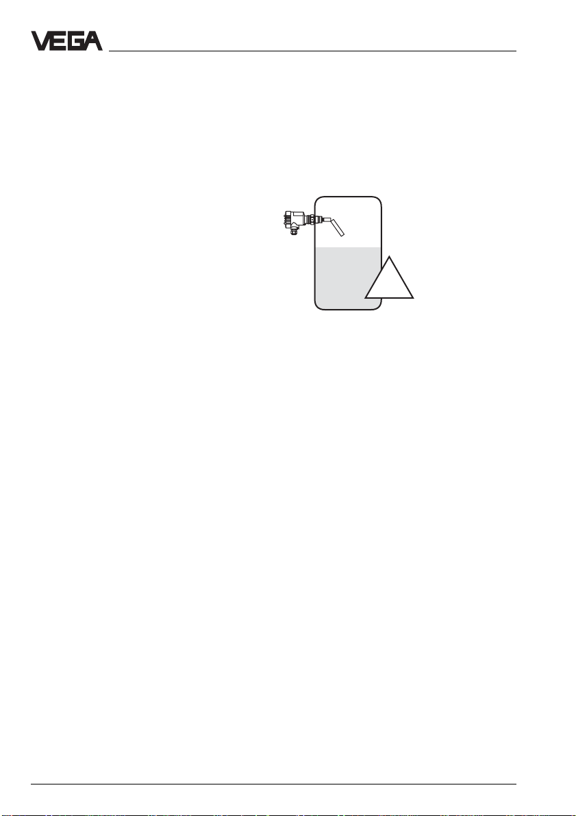
VEGATOR 521
Signal conditioning instrument as level switch
for a sensor with single point control. A horn
can be activated, if e.g. a certain level is
exceeded. If the level falls below the set
value, the horn is switched off. A typical
application for this level switch is an overfill
protection or dry run protection with one
sensor. The point that can be adjusted has a
fixed hysteresis.
off on
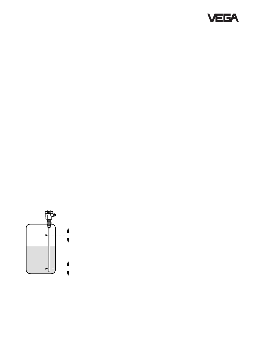
VEGATOR 522
Signal conditioning instrument as level switch
for one sensor with double point control
(adjustable hysteresis). The instrument has
two potentiometers. Both points, the switch
on and off point can be adjusted
independently. This ensures that, e.g. a filling
or emptying pump or a valve control can be
achieved.
off off
on
VEGATOR 13
Page 14

Setup
VEGATOR 523
Signal conditioning instrument as level switch
for a sensor with dual single point control.
The instrument has two potentiometers.
Therefore it is possible to achieve with one
sensor, e.g. an overfill protection and a dry
run protection or an overfill protection with
pre- or main alarm. The two points that can
be adjusted have a fixed hysteresis.
off1
1
2
on1
off2on2 on2
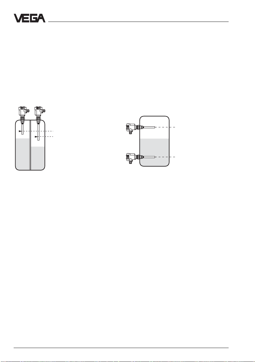
VEGATOR 527
Signal conditioning instrument as level switch
for single point control with two sensors or
double point control with two sensors (see
illustration 18). With VEGATOR 527, two
sensors can be monitored at the same time
with one signal conditioning instrument. The
two points that can be adjusted have a fixed
hysteresis.
4.3 Switching point adjustment
The following control modes are possible with
the individual instruments:
- level detection [521, 522, 523, 527]
- double point control with one sensor and
adjustable hysteresis (min./max. control)
[522]
- single point control with one sensor and 2
level switches [523]
- two single point controls with 2 sensors
[527]
- double point control with 2 sensors [527]
Note
In general, the relay control lamp shows the
activated (energised) condition of the relay. A
dark control lamp means that the relay is
deenergised. This means also that in case of
power failure the relay always returns to
deenergised condition.
VEGATOR 521
Single point control
Please note for single point control also "4.1
Indicating and adjustment elements" (the
numbers in brackets refer to the illustration).
off1
1
2
12
14 VEGATOR
on1
on2 off2
Page 15
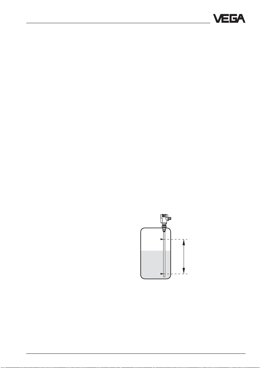
Setup
Vertically installed measuring probes and
pressure transmitters
Fill the vessel to the requested level.
On the DIL switch block (14) you select the
mode (A - overfill protection, B - dry run
protection).
Make sure that the integration time is
switched off. The switches 2 - 6 on the DIL
switch block (14) must be in Off position. Set
the potentiometer (6) to 0.
Turn the potentiometer (6) very slowly
clockwise until the relay control lamp (7)
lights (mode A) or extinguishes (mode B).
If necessary, choose the following
adjustments on the DIL switch block (14):
- switch off delay, switch on delay
- integration time (0.2 … 20 s)
VEGATOR is now ready for operation.
Horizontally mounted meas. probes and
meas. probes for very adhesive products
On the DIL switch block (14) you select the
mode (A - overfill protection, B - dry run
protection).
Make sure that the integration time is
switched off. The switches 2 - 6 on the DIL
switch block (14) must be in Off position. Set
the potentiometer (6) to 0.
Fill the vessel until the measuring probe is
covered completely. In case of measuring
probes for very adhesive products, the sensitive tip (standard 100 mm) must be totally
covered.
Turn the potentiometer (6) very slowly
clockwise until the relay control lamp (7)
lights (mode A) or extinguishes (mode B).
Now note the adjusted value.
Set the potentiometer (6) to the average
value of the two noted values.
If necessary, choose the following
adjustments on the DIL switch block (14):
- switch off delay, switch on delay
- integration time (0.2 … 20 s)
VEGATOR is now ready for operation.
VEGATOR 522
Double point control with one sensor
and adjustable hysteresis
For switch point adjustment, please also note
"4.1 Indicating and adjustment elements" (the
numbers in brackets refer to the illustration).
1
Lower the level at least down to 100 mm
below the measuring probe.
Turn the potentiometer (6) very slowly
clockwise until the relay control lamp (7)
2
lights (mode A) or extinguishes (mode B).
Now note the adjusted value.
VEGATOR 15
Page 16
Setup
Vertically mounted measuring probes or
pressure transmitters
Fill the vessel to the required max. level.
Make sure that the integration time is
switched off. The switches 2 - 6 on the DIL
switch block (14) and the changeover switch
(13) must be in Off position.
On the DIL switch block (14) you select the
mode (A - overfill protection, B - dry run
protection).
Set the min. potentiometer (6) to 0 and the
max. potentiometer (3) to 10.
If you have chosen mode A, the relay control
lamp (7) must light. If the control lamp does
not light, turn the min. potentiometer (6)
shortly to 10, to activitate the relay control
lamp. Then turn the min. potentiometer again
to 0.
If you have chosen mode B, the relay control
lamp (7) should not light. If the control lamp
lights, turn the min. potentiometer (6) shortly
to 10, to deactivate the relay control lamp.
Then turn the min. potentiometer again to 0.
Turn the max. potentiometer (3) very slowly
anticlockwise until the relay control lamp
lights or extinguishes.
VEGATOR 522
Single point control with safety
monitoring
Note for the switch point adjustment "4.1
Indicating and adjustment elements" (the
numbers in brackets refer to the illustration).
!
Only possible with horizontally mounted
meas. probes or meas. probes for very
adhesive products
Make sure that the integration time is
switched off. The switches 2 - 6 on the DIL
switch block (14) must be in Off position.
Lower the medium until the probe is
uncovered. The level should be at least
=100 mm below the probe.
Lower the medium to the required min. level.
Turn the min. potentiometer (6) very slowly
clockwise until the relay control lamp lights or
extinguishes.
If necessary, choose the following
adjustments on the DIL switch block (14):
- switch off delay, switch on delay
- integration time (0.2 … 20 s)
VEGATOR is now ready for operation.
16 VEGATOR
Set the changeover switch for the variable
fail-safe adjustment (13) to "on". Set the two
potentiometers (3 and 6) to 0. The red failure
lamp (8) extinguishes.
Turn the max. potentiometer (3) to 10. The
red failure lamp (8) lights. Turn the max.
potentiometer very slowly clockwise until the
relay control lamp (7) extinguishes. Turn the
max. potentiometer (3) another step
anticlockwise.
Turn the min. potentiometer (6) very slowly
clockwise until the relay control lamp (7)
lights or extinguishes. Note this value.
Page 17
Setup
Fill the vessel until the measuring probe is
covered completely or is submerged into the
medium by approx. 100 mm. The relay
control lamp (7) changes switching condition.
Turn the min. potentiometer (6) very slowly
clockwise until the relay control lamp (7)
lights or extinguishes.
Note the value of the potentiometer. Set the
potentiometer (6) to the average value of the
two noted values.
If necessary, choose the following
adjustments on the DIL switch block (14):
- switch off delay, switch on delay
- integration time (0.2 … 20 s)
VEGATOR is now ready for operation.
VEGATOR 523
Single point control with one sensor
and two level switches
Note for switch point adjustment "4.1
Indicating and adjustment elements" (the
numbers in brackets refer to the illustration).
For min. and max. information, max. and
max. alarm or min. and min. alarm
information
Make sure that the integration time is
switched off. The switches 2 - 6 of the DIL
switch blocks (14 and 15) must be in Off
position.
Choose on the DIL switch blocks (14 and 15)
the mode (A - overfill protection, B - dry run
protection).
Set the two potentiometers (3 and 6) to 0.
Lower the medium to the required min. level.
Turn the min. potentiometer (6) very slowly
clockwise until the relay control lamp (7)
lights or extinguishes.
Fill the vessel to the required max. level.
Turn the max. potentiometer (3) very slowly
clockwise until the relay control lamp (4)
lights or extinguishes.
If necessary, choose the following
adjustments on the DIL switch blocks (14
and 15):
- switch off delay, switch on delay
- integration time (0.2 … 20 s)
VEGATOR is now ready for operation. (see
1
2
VEGATOR 17
also illustration 7 c).
Page 18
Setup
VEGATOR 527
Single point control with 2 sensors
For switch point adjustment also note "4.1
Indicating and adjustment elements" (the
numbers in brackets refer to the illustration).
Vertically mounted measuring probes and
pressure transmitters
1
2
12
Choose on the DIL switch blocks (14 and 15)
the mode (A - overfill protection, B - dry run
protection). Make sure that the integration
time is switched off. The switches 2 - 6 of the
DIL switch blocks (14 and 15) and the min./
max. changeover switch (12) must be in Off
position. Set the two potentiometers (3 and 6)
to 0.
Channel 1
Fill the vessel to the required level. Turn the
potentiometer (3) very slowly clockwise until
the relay control lamp (4) lights (mode A) or
extinguishes (mode B).
Channel 2
Carry out the adjustment for channel 1. Then
repeat the adjustment with the adjustment
elements for channel 2.
If necessary, choose the following
adjustments on the DIL switch blocks (14
and 15):
- switch off delay, switch on delay
- integration time (0.2 … 20 s)
VEGATOR is now ready for operation.
Horizontally mounted meas. probes and
meas. probes for very adhesive products
1
2
Choose on the DIL switch blocks (14 and 15)
the mode (A - overfill protection, B - dry run
protection). Make sure that the integration
time is switched off. The switches 2 - 6 of the
DIL switch blcoks (14 and 15) and the min./
max. changeover switch (12) must be on in
Off position. Set the two potentiometers (3
and 6) to 0.
Channel 1
Lower the level at least 100 mm below
electrode 1.
Turn the potentiometer (3) very slowly
clockwise until the relay control lamp (4)
lights (mode A) or extinguishes (mode B).
Note the value adjusted now.
Fill the vessel until electrode 1 is covered
completely. With electrodes for very adhesive
products, the sensitive tip (standard
100 mm) must be covered completely.
18 VEGATOR
Page 19

Setup
Turn the potentiometer (3) very slowly
clockwise until the relay control lamp (4)
lights (mode A) or extinguishes (mode B).
Note the value adjusted now.
Set the potentiometer (3) to the average
value of the two noted values.
Channel 2
Carry out the adjustment like for channel 1.
Then repeat the adjustment with the
adjustment elements for channel 2.
If necessary, choose the following
adjustments on the DIL switch blocks (14
and 15):
- switch off delay, switch on delay
- integration time (0.2 … 20 s)
VEGATOR is now ready for operation.
VEGATOR 527
Double point control with 2 sensors
For switch point adjustment also note "4.1
Indicating and adjustment elements" (the
numbers in brackets refer to the illustration).
Choose on the DIL switch blocks (14 and 15)
the mode (A - overfill protection, B - dry run
protection). Make sure that switch 1 of the
two DIL switch blocks (14 and 15) is
adjusted to the same mode (both the mode A
or both the mode B)
Set the min./max. changeover switch (12) to
off.
After having selected mode A, make sure
that the meas. probe of channel 1 is always
mounted in a higher position than the meas.
probe for channel 2.
In mode B, the meas. probe of channel 1
must be mounted lower than the meas. probe
of channel 2.
Make sure that the integration time is
switched off. The switches 2 - 6 of the DIL
switch blocks (14 and 15) must be in Off
position. Set the potentiometer (3) to 0.
Channel 1
Lower the level at least 100 mm below the
measuring probe 1.
Turn the potentiometer (3) very slowly
clockwise until the relay control lamp (4)
lights (mode A) or extinguishes (mode B).
Note the adjusted value now.
1
Fill the vessel until the measuring probe is
covered completely. With measuring probes
for very adhesive products, the sensitive tip
(standard 100 mm) must be covered
completely.
2
Turn the potentiometer (3) very slowly
clockwise until the relay control lamp (4)
lights (mode A) or extinguishes (mode B).
Note the adjusted value now.
Horizontally mounted meas. probes or
Set the potentiometer (3) to the average
meas. probes for very adhesive products
Here, signals of two measuring probes, e.g.
mounted to min. or max. levels, can be linked
to one common pump control signal.
VEGATOR 19
Page 20

value of the two noted values.
Channel 2
Carry out the adjustment like for channel 1.
Then repeat the adjustment with the
adjustment elements for channel 2.
Set the min./max. changeover switch (12) to
"on".
The relay of channel 1 now has the function of
a min./max. relay (hysteresis signal). The
relay of channel 2 still signals the covering of
electrode 2.
If necessary, choose the following
adjustments on the DIL switch blocks (14
and 15):
- switch off delay, switch on delay
- integration time (0.2 … 20 s)
VEGATOR is now ready for operation.
Setup
20 VEGATOR
Page 21

Diagnostics
5 Diagnostics
5.1 Maintenance
The instrument is maintenance free.
5.2 Repair
Repairs require accessing internal parts of
the instrument to correct an instrument defect. For safety and warranty reasons, repair
must only be carried out by VEGA personnel.
In case of a defect, please return the respective instrument with a short description of the
flaw to our repair department.
Failures, their possible causes and their
rectification are listed under “5.3 Failure
rectification“.
VEGATOR 21
Page 22

Diagnostics
5.3 Failure rectification
Fai lur e Rectification / Measure
Instrument is dead /
Green operating
control lamp
extinguishes Check the voltage supply and the mains connections as described
Red failure LED
lights Check the sensor inputs for the following failures:
under “Connection instructions“ on page 8. If the instrument still
does not function, please call our service department.
- short circuit on the input
- sensor not connected correctly or polarity-reversed
- sensor line interrupted
- supply voltage too low
Check if the sensor is connected correctly
- failures in the sensor, effecting a current change to below 2 mA or
above 23 mA, generate a fault signal on VEGATOR.
Measure the current in
the connection cable to
the sensor.
4 … 20 mA 12 … 20 V
mA
+
±
Sensor
V
28
+
+
30
-
-
32
VEGATOR
For Ex systems, make sure that the Ex protection is not degraded by the measuring instruments.
22 VEGATOR
Page 23

Diagnostics
a. Current value < 2 mA
- Check the supply voltage on the connection cable to the sensor.
The voltage should be at least 18 V.
Should a value below 18 V should be measured, it indicates a
defect in the signal conditioning instrument. In this case, return
the instrument for repair to VEGA.
- Should the red failure lamp continue to light, separate the
connection cable from the signal conditioning instrument and
connect to the sensor inputs of the signal conditioning instrument
a resistor of 1 kOhm.
If the failure lamp continues to light, the signal conditioning
instrument is defective. In such a case, return the instrument for
repair to VEGA.
- Should the failure lamp extinguish, reconnect the signal
conditioning instrument. Separate the sensor from the connection
cable and connect a resistor of 1 kOhm in its place.
- Should the failure lamp continue to light, there is probably a short
circuit in the connection line. Check the connection cable to the
sensor.
- If the failure lamp extinguishes, the sensor is defective. Check the
connected sensor.
b. Current value > 22 mA
- Check all connections and the connection cable to the sensor.
- Should the red failure lamp continue to light, separate the sensor
from the connection cable and connect a resistor of 1 kOhm in its
place.
If the failure lamp extinguishes, the sensor is defective. Check the
connected sensor.
- Should the failure lamp continue to light, reconnect the sensor.
Separate the signal conditioning instrument from the connection
cable and connect a resistor of 1 kOhm to its sensor input.
- Should the failure lamp continue to light, the signal conditioning
instrument is defective. In such a case, return the instrument for
repair to VEGA.
- If the failure lamp extinguishes, there is probably a short circuit in
the connection line. Check the connection cable to the sensor.
VEGATOR 23
Page 24

VEGA Grieshaber KG
Am Hohenstein 113
D-77761 Schiltach
Phone (0 78 36) 50 - 0
Fax (0 78 36) 50 - 201
e-mail info@vega-g.de
ISO 9001
The statements on types, application, use and operating conditions of
the sensors and processing systems correspond to the latest information at the time of printing.
Technical data subject to alterations
19312-EN-041110
 Loading...