

Page 1

Operating Instructions
in
out
VEGATOR 256C
Signal conditioning instrument
Signal conditioning instruments
and communication
Page 2

Contents
Contents
1 About this document
1.1 Function .............................
1.2 Target group ..........................
1.3 Symbolism used .......................
2 For your safety
2.1 Authorised personnel ....................
2.2 Appropriate use........................
2.3 Warning about misuse ...................
2.4 General safety instructions ................
2.5 CE conformity .........................
2.6 Safety instructions for Ex areas ............
2.7 Environmental instructions ................
3 Product description
3.1 Configuration..........................
3.2 Principle of operation ....................
3.3 Operation ............................
3.4 Storage and transport ...................
4 Mount
4.1 General instructions.....................
4.2 Mounting instructions....................
4
4
4
5
5
5
5
5
6
6
7
7
7
8
9
9
5 Connecting to power supply
5.1 Preparing the connection .................
5.2 Wiring plan ...........................
6 Set up
6.1 Adjustment system .....................
6.2 Adjustment elements ....................
6.3 Switching point adjustment................
7 Maintenance and fault rectification
7.1 Maintenance ..........................
7.2 Remove interferences ...................
7.3 Instrument repair .......................
8 Dismounting
8.1 Dismounting steps ......................
8.2 Disposal .............................
2 VEGATOR 256C - Signal conditioning instrument
10
10
13
13
13
15
15
15
17
17
23409-EN-070316
Page 3

9 Supplement
9.1 Technical data.........................
9.2 Dimensions ...........................
Contents
18
20
23409-EN-070316
VEGATOR 256C - Signal conditioning instrument 3
Page 4
About this document
1 About this document
1.1 Function
This operating instructions manual has all the information you
need for quick setup and safe operation. Please read this
manual before you start setup.
1.2 Target group
This operating instructions manual is directed to trained,
qualified personnel. The contents of this manual should be
made available to these personnel and put into practice by
them.
1.3 Symbolism used
Information, tip, note
This symbol indicates helpful additional information.
Caution: If this warning is ignored, faults or
malfunctions can result.
Warning: If this warning is ignored, injury to persons and/or
serious damage to the instrument can result.
Danger: If this warning is ignored, serious injury to persons
and/or destruction of the instrument can result.
Ex applications
This symbol indicates special instructions for Ex applications.
l List
The dot set in front indicates a list with no implied sequence.
à Action
This arrow indicates a single action.
1 Sequence
Numbers set in front indicate successive steps in a procedure.
4 VEGATOR 256C - Signal conditioning instrument
23409-EN-070316
Page 5

For your safety
2 For your safety
2.1 Authorised personnel
All operations described in this operating instructions manual
must be carried out only by trained specialist personnel
authorised by the operator. For safety and warranty reasons,
any internal work on the instruments must be carried out only
by personnel authorised by the manufacturer.
2.2 Appropriate use
VEGATOR 256C is a universal signal conditioning instrument
for connection of a level switch.
You can find detailed information on the application range of
VEGATOR 256C in chapter "Product description".
2.3 Warning about misuse
Inappropriate or incorrect use of the instrument can give rise to
application-specific hazards, e.g. vessel overfill or damage to
system components through incorrect mounting or adjustment.
2.4 General safety instructions
VEGATOR 256C is a high-tech instrument requiring the strict
observance of standard regulations and guidelines. The user
must take note of the safety instructions in this operating
instructions manual, the country-specific installation standards
(e.g. the VDE regulations in Germany) as well as all prevailing
safety regulations and accident prevention rules.
2.5 CE conformity
VEGATOR 256C is in CE conformity with EMC (89/336/EWG)
and LVD (73/23/EWG) as well as 93/68/EWG.
Conformity has been judged according to the following
standards:
l EMC:
- Emission EN 50081-1: 1992
- Suceptibility EN 50082-2: 1995
l LVD: EN 61010-1: 1993
23409-EN-070316
VEGATOR 256C - Signal conditioning instrument 5
Page 6

For your safety
2.6 Safety instructions for Exareas
Please note the Ex-specific safety information for installation
and operation in Ex areas. These safety instructions are part of
the operating instructions manual and come with the Exapproved instruments.
2.7 Environmental instructions
Protection of the environment is one of our most important
duties. That is why we have introduced an environment
management system with the goal of continuously improving
company environmental protection. The environment management system is certified according to DIN EN ISO 14001.
Please help us fulfil this obligation by observing the environmental instructions in this manual:
l Chapter "Storage and transport"
l Chapter "Disposal"
6 VEGATOR 256C - Signal conditioning instrument
23409-EN-070316
Page 7
3 Product description
3.1 Configuration
Product description
Scope of delivery
Components
Area of application
Functional principle
The scope of delivery encompasses:
l VEGATOR 256C signal conditioning instrument
l Documentation
- this operating instructions manual
VEGATOR 256C consists of:
l VEGATOR 256C signal conditioning instrument
min.
1
max.
2
3
200...250VAC 3VApower supply
R
Relais: max 250V, 5A, 750VA
1
2
10
0
4
5
6
L1
7
N
8
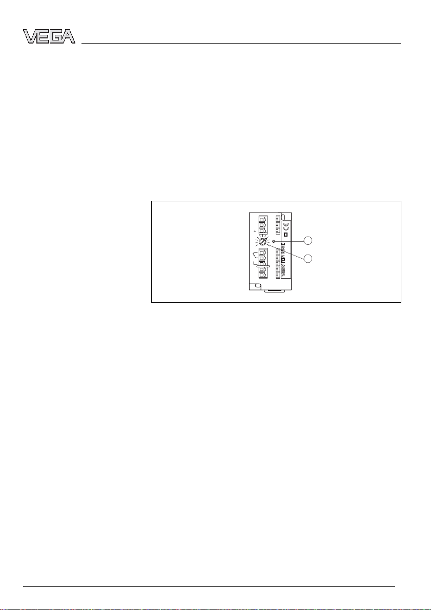
Fig. 1: VEGATOR 256C
1 Signal lamp - Relay output
2 Potentiometer for switching point adjustment
3.2 Principle of operation
VEGATOR 256C is a single signal conditioning instrument for
processing the signals of conductive probes.
VEGATOR 256C signal conditioning instrument can power
connected instruments and process their measuring signals.
Supply
You can find detailed information on the power supply in
chapter "Technical data" in the "Supplement".
3.3 Operation
A potentiometer is located on the front plate of VEGATOR
256C. With this potentiometer, the switching point can be
adjusted.
23409-EN-070316
VEGATOR 256C - Signal conditioning instrument 7
Page 8

Product description
3.4 Storage and transport
Packaging
Storage and transport tem-
perature
Your instrument was protected by packaging during transport.
Its capacity to handle normal loads during transport is assured
by a test according to DIN EN 24180.
The packaging of standard instruments consists of environ-
ment-friendly, recyclable cardboard. For special versions, PE
foam or PE foil is also used. Dispose of the packaging material
via specialised recycling companies.
l Storage and transport temperature see "Supplement -
Technical data - Ambient conditions"
l Relative humidity 20 … 85 %
8 VEGATOR 256C - Signal conditioning instrument
23409-EN-070316
Page 9

4 Mount
4.1 General instructions
Mount
Installation location
Mount
VEGATOR 256C signal conditioning instrument with plug-in
socket for mounting on carrier rail according to EN 50022.
4.2 Mounting instructions
You can mount the VEGATOR 256C signal conditioning
instruments either to the wall (2 screws) or plug it onto a carrier
rail.
Carrier rail mounting
Place the signal conditioning instrument onto the carrier rail
(35x7.5 according to EN 50022) from below and press the
instrument against the carrier rail until it snaps in.
Wall mounting
Fasten the instrument directly to the wall by means of two
screws (max. ø 3 mm/0.12 in).
")
32
/
5
4 mm
(
")
64
/
23
60 mm (2
/64")
7,5 mm
19
(
/64")
Fig. 2: Drilling template VEGATOR 256C
22 mm
55
(
23409-EN-070316
VEGATOR 256C - Signal conditioning instrument 9
Page 10

Connecting to power supply
5 Connecting to power supply
5.1 Preparing the connection
Note safety instructions
Select power supply
Selecting connection cable
Cable screening and ground-
ing
Always keep in mind the following safety instructions:
l Connect only in the complete absence of line voltage
l If overvoltage surges are expected, overvoltage arresters
should be installed
Tip:
We recommend VEGA overvoltage arresters B61-300 (power
supply VEGATOR 256C) and B62-36G (sensor supply).
You can find detailed information on the power supply in
chapter "Technical data" in the "Supplement".
Power supply of VEGATOR 256C is connected with standard
cable according to the national installation standards.
Standard two-wire cable without screening can be used to
connect sensors. If electromagnetic interference is expected,
screened cable must be used.
From a cable length of 50 m use one cable for each signal
conditioning instrument.
If you want to use a common cable, the min. and max. cables
must be screened. The screen must be connected to ground
on both sides.
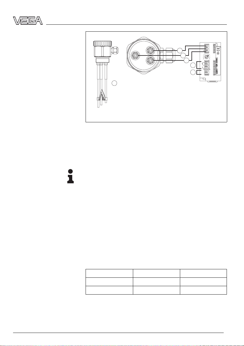
5.2 Wiring plan
Level detection
3
Fig. 3: Level detection
1 Supply
2 Relay output
3 Mass
4 max.
min.
1
max.
4
2
1
2
3
0
10
4
5
6
7
L1
8
N
10 VEGATOR 256C - Signal conditioning instrument
23409-EN-070316
Page 11
Pump control (min./max. con-
trol)
Connecting to power supply
min.
1
max.
3
2
1
5
4
3
2
1
2
3
0
10
4
5
6
7
L1
8
N
6
2
3
1
Fig. 4: Pump control
1 Supply
2 Relay output
3 Mass
4 max.
5 min.
6 Probe, e.g. EL3
Note:
Mutiple rod probes connected to several signal conditioning
instruments or to a multiple channel instrument need a ground
rod to keep the signal conditioning instruments from influencing each other.
If there are several VEGATOR 256C, it is absolutely necessary
that they be connected identically, i.e. the first supply line to all
no. 7 terminals and the second supply line to all no. 8
terminals. Exchanging no. 7 and no. 8 or connecting to
different phases is not permitted.
Exchange of a VEGATOR
256B
If you want to replace a VEGATOR 256B by a VEGATOR
256C or if you want to use a VEGATOR 256C as well as a
VEGATOR 256B on a multiple rod probe, the supply voltage
must be wired as follows.
VEGATOR 256C VEGATOR 256B
L17 7
N 85
Keep in mind that the function of the relay control lamp on
VEGATOR 256C is inverted to that of VEGATOR 256B.
23409-EN-070316
VEGATOR 256C - Signal conditioning instrument 11
Page 12

Connecting to power supply
VEGATOR 256C
The relay control lamp lights when the relay is energized and
extinguishes when the relay is deenergized.
VEGATOR 256B
The relay control lamp extinguishes when the relay is
energized and lights when the relay is deenergized.
12 VEGATOR 256C - Signal conditioning instrument
23409-EN-070316
Page 13

6 Set up
6.1 Adjustment system
min.
1
max.
2
3
10
0
4
5
200...250VAC 3VApower supply
6
R
L1
7
8
Relais: max 250V, 5A, 750VA
N
Fig. 5: Indicating and adjustment elements
1 Signal lamp - Relay output
2 Potentiometer for switching point adjustment
6.2 Adjustment elements
Set up
1
2
Control lamp
The yellow relay control lamp (LED) shows the switching
condition of the relay.
In general, the relay control lamp indicates the activated
(energised) condition of the relay.
A dark relay control lamp means that the relay is deenergised.
Potentiometer for switching
point adjustment
A potentiometer for switching point adaptation is located on the
front plate of the signal conditioning instrument. With this
potentiometer you can adapt the measuring system to the
conductivity of the product.
6.3 Switching point adjustment
Level detection
23409-EN-070316
VEGATOR 256C - Signal conditioning instrument 13
l Connecting the signal conditioning instrument to voltage
supply
l Turn potentiometer (2) to position 0
l Fill the vessel until the max. probe is covered approx. 1 cm
by the product
l Turn the potentiometer (2) slowly clockwise until the yellow
LED extinguishes
The switching sensitivity of the signal conditioning instrument
is now adapted to the conductivity of the product.
Page 14

Set up
Pump control (min./max.)
l at first, connect only the ground and max. electrode to
VEGATOR 256C (terminal 2 and 3)
l Connecting the signal conditioning instrument to voltage
supply
l Turn potentiometer (2) to position 0
l Fill the vessel until the max. probe is covered approx. 1 cm
by the product
l Turn potentiometer (2) slowly clockwise until the yellow
LED extinguishes
l Connect min. electrode to terminal 1 of VEGATOR 256C
The switching sensitivity of the signal conditioning instrument
is now adapted to the conductivity of the product, i.e. the relay
output deenergises with max. level and the yellow control lamp
extinguishes.
This switching condition remains until the level falls below the
position of the min. electrode, i.e. the relay output energizes at
min. level and the yellow control lamp lights.
The relay output deenergises again when the max. level is
reached.
14 VEGATOR 256C - Signal conditioning instrument
23409-EN-070316
Page 15

Maintenance and fault rectification
7 Maintenance and fault rectification
7.1 Maintenance
When used as directed in normal operation, VEGATOR 256C
is completely maintenance free.
7.2 Remove interferences
Causes of malfunction
Remove interferences
24 hour service hotline
Failure
VEGATOR 256C offers maximum reliability. Nevertheless,
faults can occur during operation. These may be caused by the
following, e.g.:
l Measured value from sensor not correct
l Voltage supply
l Interference on the cables
The first measures to be taken are to check the input/output
signal. In many cases, the causes can be determined this way
and the faults rectified.
However, should this measures not be successful, call the
VEGA service hotline in urgent cases under the phone no. +49
1805 858550.
The hotline is available to you 7 days a week round-the-clock.
Since we offer this service world-wide, the support is only
available in the English language. The service is free of
charge, only the standard telephone costs will be charged.
? The signal conditioning instrument does not switch when
the respective probe is covered or uncovered
l Conductivity of the product too low
à Check if the conductivity value of your product is at
least 7.5 µS/cm
l Line break to the sensor
à Check the connection cables from the probe to the
signal conditioning instrument
7.3 Instrument repair
If a repair is necessary, please proceed as follows:
You can download a return form (23 KB) in the Internet from
our homepage
and Certificates - Repair form".
23409-EN-070316
VEGATOR 256C - Signal conditioning instrument 15
www.vega.com under: "Downloads - Forms
Page 16

Maintenance and fault rectification
By doing this you help us carry out the repair quickly and
without having to call for needed information.
l Print and fill out one form per instrument
l Clean the instrument and pack it damage-proof
l Attach the completed form and probably a safety data
sheet outside on the packaging
l Please ask the agency serving you for the address of your
return shipment. You find the respective agency on our
website
www.vega.com under: "Company - VEGA world-
wide"
16 VEGATOR 256C - Signal conditioning instrument
23409-EN-070316
Page 17

Dismounting
8 Dismounting
8.1 Dismounting steps
Take note of chapters "Mounting" and "Connecting to power
supply" and carry out the listed steps in reverse order.
8.2 Disposal
The instrument consists of materials which can be recycled by
specialised recycling companies. We use recyclable materials
and have designed the electronics to be easily separable.
WEEE directive 2002/96/EG
This instrument is not subject to the WEEE directive 2002/96/
EG and the respective national laws (in Germany, e.g.
ElektroG). Pass the instrument directly on to a specialised
recycling company and do not use the municipal collecting
points. These may be used only for privately used products
according to the WEEE directive.
Correct disposal avoids negative effects to persons and
environment and ensures recycling of useful raw materials.
Materials: see chapter "Technical data"
If you cannot dispose of the instrument properly, please
contact us about disposal methods or return.
23409-EN-070316
VEGATOR 256C - Signal conditioning instrument 17
Page 18

Supplement
9 Supplement
9.1 Technical data
General data
Series Module unit for mounting on carrier rail 35x7.5
or 35x15 according to EN 50022
Dimensions W = 37 mm (1.46 in), H = 68 mm (2.68 in), D =
66 mm (2.6 in)
Weight approx. 170 g (6 oz)
Housing material Noryl SE100, Lexan 920A
Voltage supply
Supply voltage
- Standard 200 … 250 VAC, 50/60 Hz
- optional 24 V, 42 V, 48 V, 100 … 130 VAC(+10 %,
-15 %)
Power consumption 1 VA
Sensor input
Quantity 1x
Response resistor 1 … 200 kOhm adjustable
Measuring circuit approx. 12 V eff., max. 1 mA
Switching hysteresis approx. 20 %
level detection or 1x pump control (min./
max.)
Relay output
Quantity 1 (1x level detection)
Mode Max. detection or overfill protection
Integration time approx. 500 ms
Contact Changeover contact (spdt)
Contact material AgNi 0.15 hard gold-plated
Turn-on voltage min. 10 mVDC, max. 250 VAC, 250 VDC
Switching current min. 10 µAD
Breaking capacity max. 750 VA, max. 54 W
Adjustment elements
Control lamp to the indication of the relay switching status
Potentiometer to the adaptation of the product conductivity
18 VEGATOR 256C - Signal conditioning instrument
C, max. 5 AAC, 1 ADC
23409-EN-070316
Page 19

Ambient conditions
Ambient temperature -20 … +50 °C (-4 … +122 °F)
Storage and transport temperature -40 … +70 °C (-40 … +158 °F)
Electromechanical data
Spring-loaded terminals for wire cross-section up to 1.5 mm²
(0.0023 in²)
Electrical protective measures
Protection IP 20
Protection class II
Supplement
23409-EN-070316
VEGATOR 256C - Signal conditioning instrument 19
Page 20
Supplement
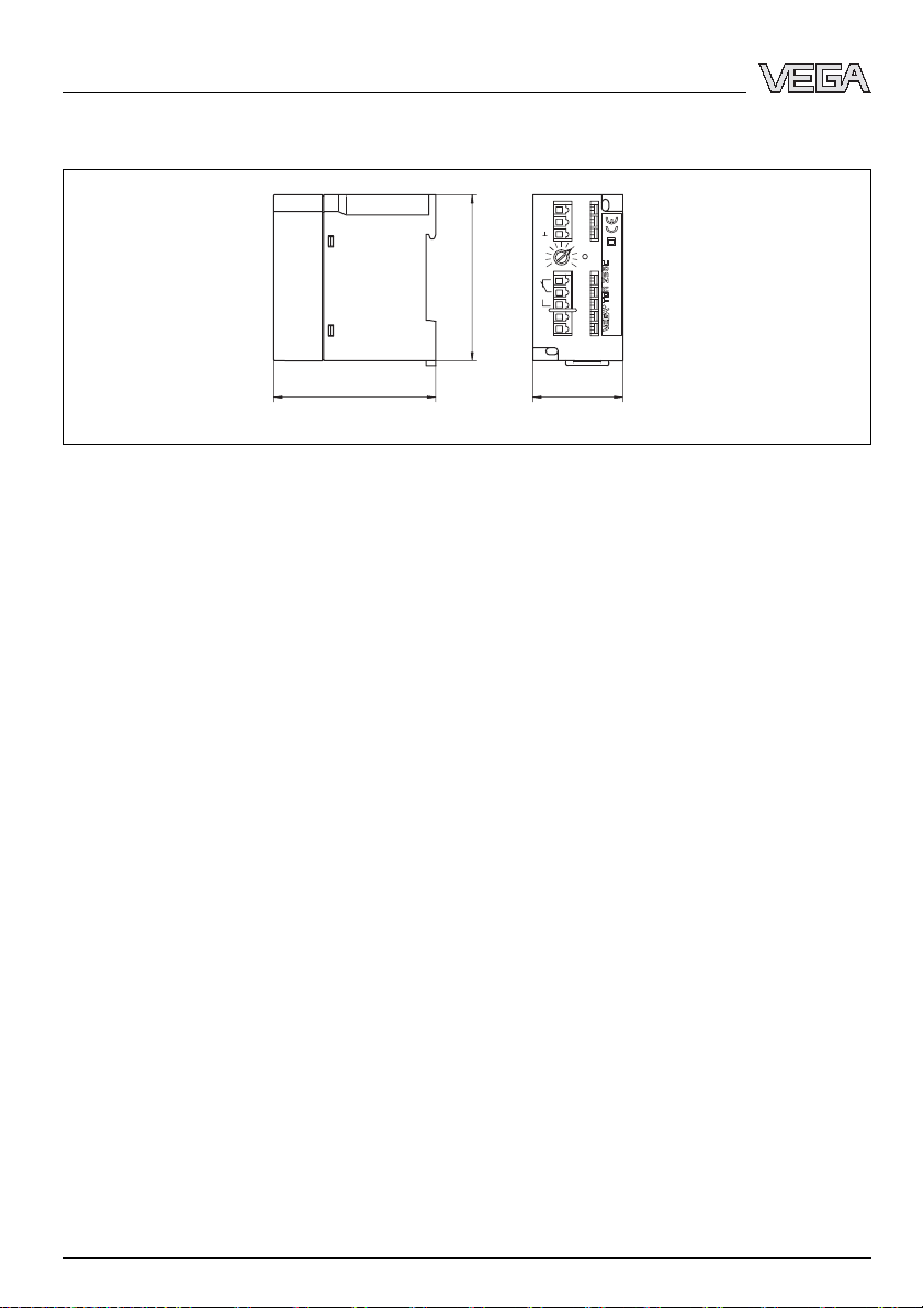
9.2 Dimensions
")
64
/
43
68 mm (2
min.
1
max.
2
3
10
0
4
5
200...250VAC 3VApower supply
6
R
L1
7
N
Relais: max 250V, 5A, 750VA
8
Fig. 6: Dimensions VEGATOR 256C
66 mm (1 19/32")
37 mm
29
(1
/64")
20 VEGATOR 256C - Signal conditioning instrument
23409-EN-070316
Page 21

Supplement
23409-EN-070316
VEGATOR 256C - Signal conditioning instrument 21
Page 22

Supplement
22 VEGATOR 256C - Signal conditioning instrument
23409-EN-070316
Page 23

Supplement
23409-EN-070316
VEGATOR 256C - Signal conditioning instrument 23
Page 24

VEGA Grieshaber KG
Am Hohenstein 113
77761 Schiltach
Germany
Phone +49 7836 50-0
Fax +49 7836 50-201
E-mail: info@de.vega.com
www.vega.com
ISO 9001
All statements concerning scope of delivery, application,
practical use and operating conditions of the sensors and
processing systems correspond to the information avail-
able at the time of printing.
© VEGA Grieshaber KG, Schiltach/Germany 2007
Subject to change without prior notice 23409-EN-070316
 Loading...