

Page 1
Page 2

Table of Contents
TX300s_Platform_Manual_RevB00
Page 2 of 104
1.0 About This User Manual
2.0 Safety Information
3.0 Introduction
3.1 Platform Overview
3.2 Front Panel
3.2.1 LED's
3.2.2 Key Pad
3.2.3 Touch Screen
3.3 Battery
3.3.1 Battery Overdraw Protection
3.4 Hardware Configurations
3.5 Home Screen
3.6 Quick Access Menu
4.0 Getting Started
4.1 Initial Settings
4.1.1 Change language and user interface style
4.1.2 Change the time zone and current time
4.1.3 Change other settings
4.2 Launching Test Applications
4.3 Understanding Test Application GUI
5.0 Utilities
5.1 Platform Settings
5.1.1 About
5.1.2 Screen Calibration
5.1.3 Bluetooth
5.1.4 Power
5.1.5 Backlight
Page 3

5.1.6 Global Settings
TX300s_Platform_Manual_RevB00
Page 3 of 104
5.1.7 Date and Time
5.1.8 Remote Access
5.1.9 EZ Remote
5.1.10 VF Noise Calibration (Microphone)
5.1.11 Maps Downloader
5.1.12 High Precision Clock Sources
5.2 Help
5.3 VeExpress
5.4 R-Server (Advanced Management)
5.5 Software Upgrade
6.0 File Manager
6.1 File Manager: Working with Saved Results, Profiles, Images
6.2 USB Memory Browser
6.3 Manage SD Card
7.0 Tools
7.1 IP Tools
7.2 Net Wiz
7.3 WiFi Wiz
7.4 ARP Wiz
7.5 Advanced Tools
7.5.1 Fiber Scope
7.5.2 Optical Power Meter (OPM)
7.5.3 WiFi Spectrum Analyzer
7.5.4 Data Card
7.5.5 WiFi inSSIDer
7.5.6 OTDR Viewer
7.5.7 GNSS Operation
7.5.8 GNSS Sky View
Page 4

7.6 Web Browser
TX300s_Platform_Manual_RevB00
Page 4 of 104
8.0 Warranty and Software
9.0 Certification and Declarations
10.0 About VeEX
Go back to TOC
Page 5

1.0 About This User Manual
TX300s_Platform_Manual_RevB00
Page 5 of 104
This user manual is suitable for novice, intermediate, and experienced users and is intended to help you successfully use the
features and capabilities of the test platform. It is assumed that you have basic computer experience and skills, and are familiar with
IP and telecommunication concepts, terminology, and safety.
Every effort was made to ensure that the information contained in this manual is accurate. However, information is subject to change
without notice. We accept no responsibility for any errors or omissions. In case of discrepancy, the web version takes precedence
over any printed literature.
(c) Copyright 2019 VeEX Inc. All rights reserved. VeEX, VePAL are registered trademarks of VeEX Inc. and/or its affiliates in the
USA and certain other countries. All trademarks or registered trademarks are the property of their respective companies. No part of
this document may be reproduced or transmitted electronically or otherwise without written permission from VeEX Inc.
This device uses software either developed by VeEX Inc. or licensed by VeEX Inc. from third parties. The software is confidential
and proprietary of VeEX Inc. The software is protected by copyright and contains trade secrets of VeEX Inc. or VeEX's licensors.
The purchaser of this device agrees that it has received a license solely to use the software as embedded in the device, and the
purchaser is prohibited from copying, reverse engineering, decompiling, or disassembling the software.
For more technical resources, visit the VeEX Inc. web site at
this product, call or e-mail our customer care department for customer support. Before contacting our customer care department,
have the product serial number and software version ready. Please go to the Basic Operations section for details on locating the unit
serial number in the menus or locate the serial number on the back of the chassis. Please provide this number when contacting
VeEX customer service.
Customer Care:
Phone: + 1 510 651 0500
E-mail:
Website:www.veexinc.com
Go back to TOC
www.veexinc.com. For assistance or questions related to the use of
Page 6

2.0 Safety Information
TX300s_Platform_Manual_RevB00
Page 6 of 104
Safety precautions should be observed during all phases of operation of this instrument. The instrument has been designed to
ensure safe operation however please observe all safety markings and instructions. Do not operate the instrument in the presence
of flammable gases or fumes or any other combustible environment. VeEX Inc. assumes no liability for the customer's failure to
comply with safety precautions and requirements.
Optical Connectors
The test platform displays a laser warning icon when the laser source is active to alert the user about a potentially dangerous
situation. It is recommended to:
1.
Deactivate the laser before connecting or disconnecting optical cables or patchcords.
2. Never look directly into an optical patchcord or an optical interface (e.g. CFP, CFP2, CFP4, QSFP+, SFP+, SFP, OTDR, LS,
while the laser is enabled. Even though optical transceivers are typically fitted with Class 1 lasers, which are considered
VFL)
eye safe, optical radiation for an extended period can cause irreparable damage to the eyes.
3.
Never use a fiber microscope to check the optical connectors when the laser source is active.
Electrical Connectors
Telephone lines may carry dangerous voltages. Always connect the electrical test ports to known test interfaces which carry low
level signals.
Safe Module Handling
While replacing test modules, all work on the open panel must be performed only by suitably qualified personnel who are familiar
with the dangers both to people and to the instrument itself.
Modules are not hot swappable. The platform must be turned off and unplugged from VAC mains when removing or inserting
test modules.
For safety and EMC (Electromagnetic Compatibility), empty module slots must be properly covered with blank panel covers.
Prevent foreign objects from entering the TX300s, before, during and after module exchange or re-configuration process.
They could create short circuits or damage internal fans.
Always store test modules by themselves in individual ESD protected packaging (with no loose elements, like screws or
tools).
Lithium-ion Battery Precautions
Lithium-ion (Li-ion) battery packs are compact and offer high capacity and autonomy, which make them ideal for demanding
applications, like providing long lasting power to portable test equipment. For safety reasons, due to their high energy concentration,
these battery packs and products containing them must be used, charged, handled, and stored properly, according to the
manufacturer’s recommendations.
Li-ion battery packs contain individual Li-ion cells as well as battery monitoring and protection circuitry, sealed in their plastic
container that must not be disassembled or serviced.
The test set unit's battery pack is also fitted with a safety connector to prevent accidental short circuits and reverse polarity.
Always charge the unit's battery pack inside the test platform battery bay using the AC/DC adapter supplied by VeEX.
Do not charge or use the battery pack if any mechanical damage is suspected (shock, impact, puncture, crack, etc).
Do not continue charging the battery if it does not recharge within the expected charging time
Storage: For long term storage, the battery pack should be stored at 20°C/68°F (room temperature), charged to about 30 to
Page 7
50% of its capacity. Spare battery packs should be charged and used at least once a year to prevent over-discharge (rotate
them regularly).
TX300s_Platform_Manual_RevB00
Page 7 of 104
It is recommended to charge and use battery packs at least every three months. Battery packs must not go without
recharging (reconditioning) for more than six months.
After extended storage, battery packs may reach a deep discharge state or enter into sleep mode. For safety reasons, Li-ion
batteries in deep discharge state may limit the initial charging current (pre-recharge) before starting their regular fast charging
cycle. The pre-charging state may take several hours.
Air transportation of Li-ion batteries is regulated by United Nations' International Air Transportation Association (IATA)
Dangerous Goods Regulations and by country-specific regulations. Please check local regulations and with common carriers
before shipping Li-ion battery packs or products containing relatively large Li-ion battery packs.
Electrical Connectors
Telephone lines may carry dangerous voltages. Always connect the electrical test ports to known test interfaces which carry low
level signals.
ESD: Electrostatic Discharge Sensitive Equipment
Test modules could be affected by electrostatic discharge. To minimize the risk of damage
when replacing or handling test modules, make sure to follow proper ESD procedures and
dissipate any electrostatic charge from your body and tools and use proper grounding gear.
Perform all work at a workplace that is protected against electrostatic build-up and
discharging.
Never touch any exposed contacts, printed circuit boards or electronic components.
Always store test modules in ESD protected packaging.
Wear ESD protection and grounding gear when:
Inserting, extracting, or handling test modules.
Inserting or removing SFPs, XFPs, QSFPs, or CFPs from the platform.
Connecting or disconnecting cables from modules or platform.
Go back to TOC
Page 8

3.0 Introduction to TX300s Series
TX300s_Platform_Manual_RevB00
Page 8 of 104
VeEX® TX300s series test sets are portable test solutions, with flexible configurations, for Core, Transport, Metro and Access
Networks
Go back to TOC
carrying Data, Voice, and Video.
All-in-one hardware platform reduces CAPEX
The VeExpress ecosystem allows users to Buy, Rent, Lease-to-own and share test feature licenses to optimize OPEX
Optimized for the field engineers or technicians installing and maintaining Transport, Carrier Ethernet, Storage Area Network,
Fiber Optics, backhaul and fronthaul mobile networks
Full support for legacy PDH/DSn interfaces with standard connectors (no adapters required)
Test card summary; monitor and manage up to four independent tests
Flexible Software platform allows for the multiple test applications running simultaneously
Multiple factory-installed all-inclusive hardware options, including Single & Dual-port with optional built-in OTDR
Test set connectivity via Ethernet Management interface, Wi-Fi, Bluetooth®, or Cellular Data Card for back office applications
and workflow optimization
Test profiles and thresholds
Fast and efficient test result transfer to USB memory stick
Asset Management: Maintain instrument software, manage test configurations, process measurement results and generate
customer test reports using VeExpress and VeSion cloud services
Optional built-in precision GNSS and chip-scale atomic clock references
Interchangeable Li-ion battery pack extends field testing time
Page 9
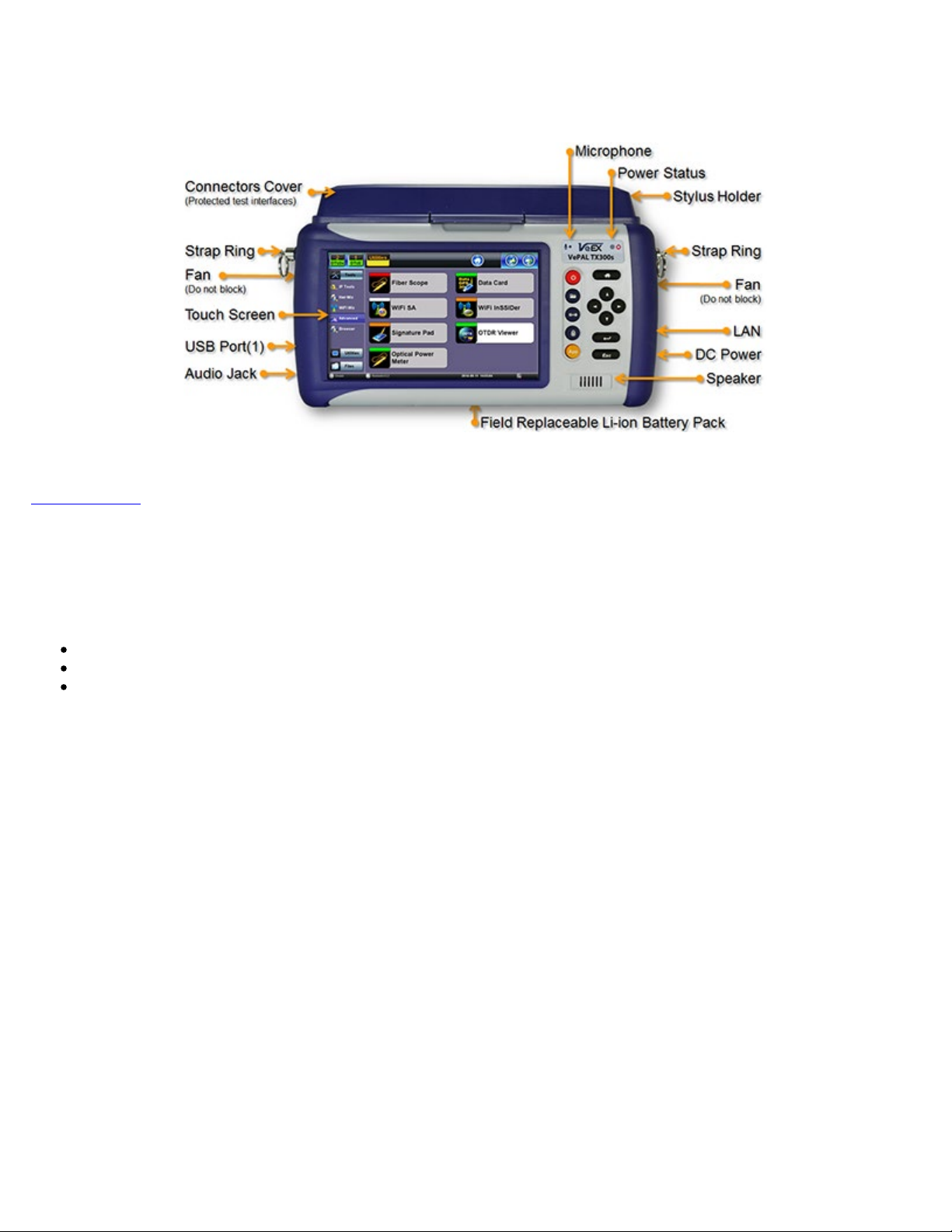
3.1 TX300s Overview
TX300s_Platform_Manual_RevB00
Page 9 of 104
Go back to TOC
3.2 Front Panel
3.2.1 LEDs
Power LED: A single LED indicates the power state of the unit.
The LED is off when the unit is powered off.
The LED is green when the unit is powered on.
The LED is orange when the unit is connected to the AC Mains and powered off (charging).
Soft LEDs:
Each tests module offers detailed soft LEDs and indicators in its test application.
Page 10
TX300s_Platform_Manual_RevB00
Page 10 of 104
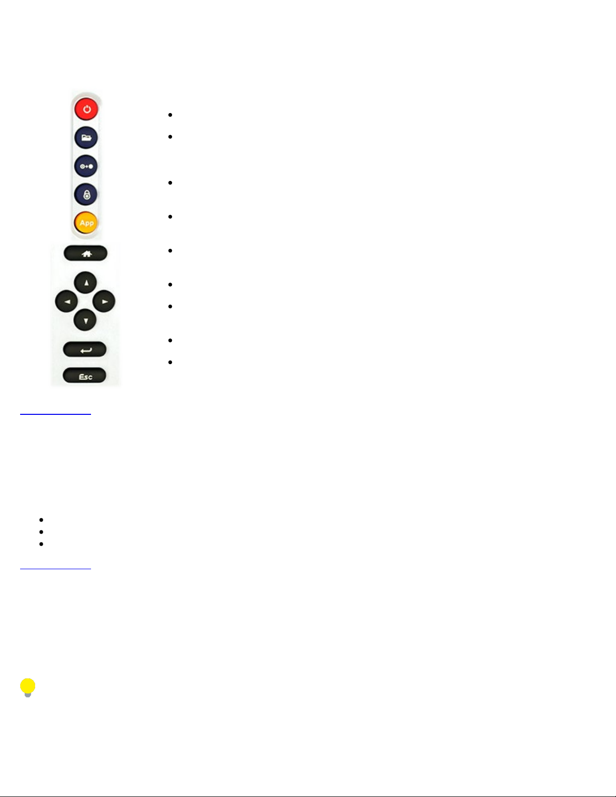
3.2.2 Key pad
Power: Press for 2 seconds to turn the test set ON or OFF (prevents accidental ON/OFF).
Save Test Results: Saves the current Test Results with customized or auto naming
(yyyymmdd-hhmmss format). The F1 key on standard keyboards can be used when
controlled via VNC
Clear History: Resets blinking LED reminders of past Errors or Alarms. Test results are not
affected. The F2 key on standard keyboards can be used when controlled via VNC
Lock/Unlock Touch Screen: Can also be programmed to capture Screen Shots (>Utilities
>Settings >Global >Save Settings). Use the F3 in standard keyboards
Test Application Selector: Quickly switches back-and-forth between two active test
applications
Home: Quickly bring users back to the Main Menu
Cursor Keys: Application dependent may offer alternative GUI Navigation to touch screen
(e.g. while wearing gloves in cold weather)
Enter: Application dependent
Escape: Application dependent
Go back to TOC
3.2.3 Touch Screen
The LCD supports touch screen operation. To operate the touch screen to navigate the menus and tabs, use the stylus located on
the right side of the unit. Please observe the following precautions:
Never use excessive pressure on the touch screen as this may damage its functionality.
Never use sharp objects such as a pen, screwdriver, etc., as this may damage the surface.
Clean the surface of the touch screen using a soft cloth and mild detergent only. Do not use alcohol.
Go back to TOC
3.3 Battery
The test set platform is equipped with a smart Li-ion rechargeable battery pack, which is located on the rear of the unit. The battery
will be partially charged upon delivery, so it is recommended to fully charge the battery before use. Please charge the battery at
room temperature to preserve its life and to obtain maximum charge. The battery is charged during operation, provided the unit is
connected to the AC Mains using the supplied AC adapter. Removing the battery while the unit is powered on is not recommended this may result in damage. Remove the rubber cover on the right side to connect the AC Main adapter to the unit.
Make sure that the key is aligned while plugging in the AC adapter to the unit. If it is not aligned,the plug will not connect to the
unit and using force will damage the connector.
Battery Charging time
The total charging time depends on the remaining battery capacity percentage and the actual current load in the TX300s. An idle
TX300s would recharge faster than an active one.
Page 11
Attention!
TX300s_Platform_Manual_RevB00
Page 11 of 104
For safety reasons, the battery charging time is always limited to a
maximum of three hours
If the TX300s is being used while charging and a full charge (100%
capacity) cannot be achieved within three hours, the charging will
automatically stop.
To resume charging, unplug the AC/DC adapter and let the TS300s work
on battery power for a minute or two and plug the AC/DC back in. This will
reset the charging circuitry.
Warning!
DO NOT disconnect the AC/DC power supply when the TX300s is running
under heavy load conditions (greater than the battery's current ratings),
such as certain multi-module multi-test applications.
If the current required is too high, but still within the battery's limits, a
warning message would be displayed when the AC/DC adapter is
unplugged, while all the tests are properly closed and TX300s shuts down.
Under overload conditions, the battery may not be able to supply enough
current to keep the test scenario running and its safety mechanisms may
shut the battery down without warning and test results may be lost.
Battery Safety precautions
For more information on safety precautions for batteries, see
Lithium-ion Battery Precautions.
Go back to TOC
Battery Power Capacity
Total Battery Power: 83.7 Watt Hours.
TX300s Platform test platform: 20 Watts
AC/DC Power Supply
When using the AC/DC power supply adapter, the total power capacity provided is 88 Watts.
Go back to TOC
3.3.1 Battery Overdraw Protection
When battery capacity declines to 10%, an audible alarm and pop-up warning displays a notification to plug in the A/C adapter or
shut down the unit. If this warning is ignored and the battery capacity is allowed to decline to under 5%, the unit will initiate a
shutdown to protect the battery from damage and for safety.
If an event, such as the AC/DC adapter being unplugged, a power interruption occurs or some other event triggers the power load to
exceed the 95W battery limit, the unit will initiate an emergency shutdown to protect the battery from damage and for safety.
During an emergency shutdown all modules power is switched off. No test files (results or configurations) are saved.
Go back to TOC
Page 12
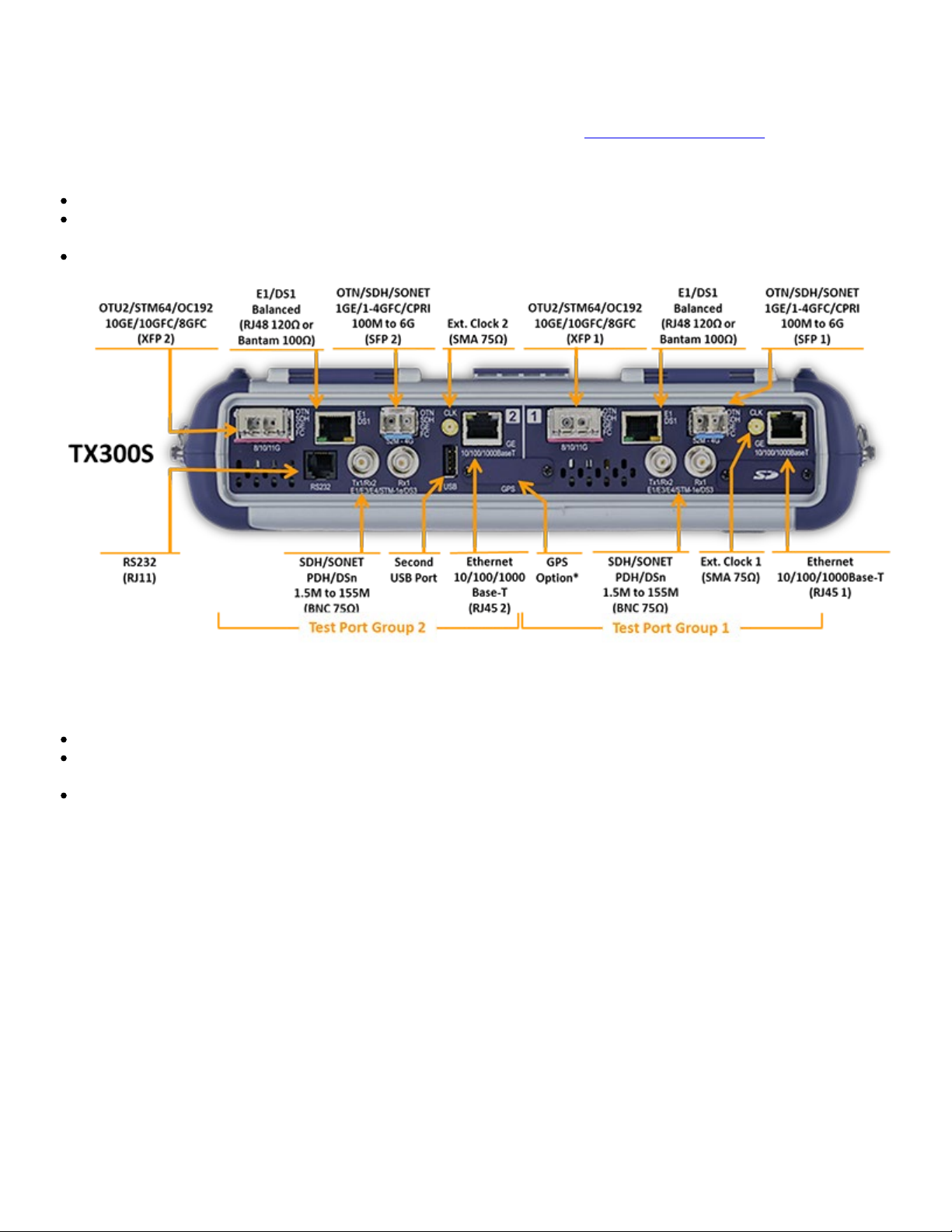
3.4 Hardware Configurations
TX300s_Platform_Manual_RevB00
Page 12 of 104
The following are examples of some test modules available for the TX300s platform. Please refer to their individual datasheets and
manuals for further details. For an up-to-date list of modules available, please visit
Two 300SM Modules - Two Single Port Groups
Configurable as Fully-Loaded Dual Port Group (Allows independent Dual Tests)
Universal multi-service test modules offer OTN/SDH/SONET/PDH/DSn, Carrier Ethernet, MPLS, Fibre Channel,
CPRI/OBSAI, Synchronization and more
Additional Technologies, Rates and Test Features can be added later, via SW licenses
www.veexinc.com/TX300S
One 300SM Module - Single Port Group
Configurable as an economical Single Port Group (Single Test)
Universal multi-service test module offers OTN/SDH/SONET/PDH/DSn, Carrier Ethernet, MPLS, Fibre Channel,
CPRI/OBSAI, Synchronization and more
Additional Technologies, Rates and Test Features can be added later, via SW licenses
Page 13
Test cards summary provides an overview of up to four running tests, as well as test application switching and management
TX300s_Platform_Manual_RevB00
Page 13 of 104
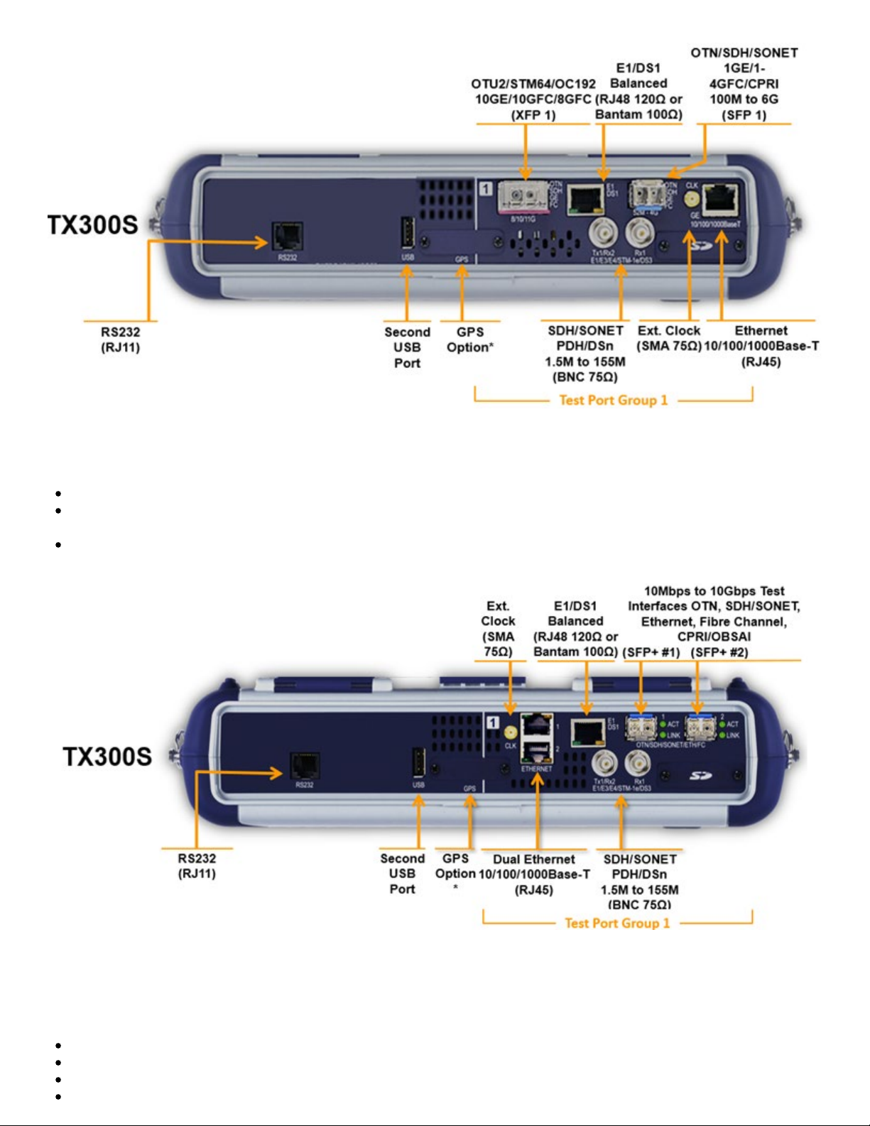
One 320S Module - Single Port Group
Configurable as an economical Single-Group Dual-Port option (Dual Tests)
Universal multi-service test module offers OTN/SDH/SONET/PDH/DSn, Carrier Ethernet, MPLS, Fibre Channel,
CPRI/OBSAI, Synchronization and more
Additional Technologies, Rates and Test Features can be added later, via SW licenses Perfect companion to the OTDR
hardware option
One 340SM Module - Single Port Group
Flexible, all-in-one multi-service test solution, from 64kbps to 16 Gbps (can be combined with 100G and OTDR modules)
Transport, Core, Metro, SAN, Backhaul and Fronthaul applications
Supports up to four test port groups with independent and simultaneous measurements
Page 14
fuctions
TX300s_Platform_Manual_RevB00
Page 14 of 104
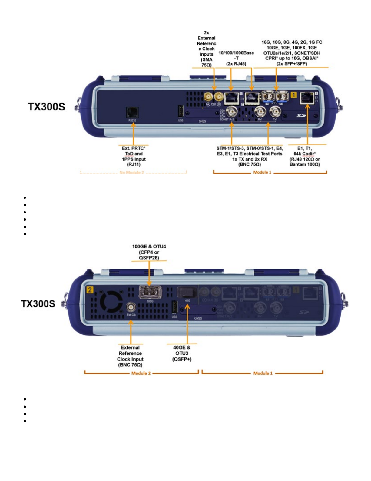
One 100G Module
Available with CFP4 or QSFP28 for 100GE and OTU4 applications
Supports IEEE 802.3bj Clause 91RS-FEC as required for SR4 (QSFP28)
QSFP+ for 40GE, OTU3
External clock interface
150 ppm clock offset generation
Soft LED indicators
OTDR Module
Fiber Optics, Transport and Service Verification, Testing & Troubleshooting
OTDR: Standard (+7dBm), High-power (+23 dBm) and PON (+23 dBm) versions
OTDR, OPM and VFL ports with interchangeable optical bulkhead connectors
This factory-installed option can be combined with any of the multi-service modules
Page 15
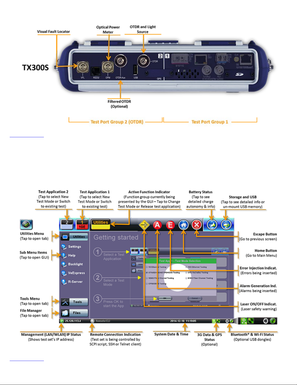
Go back to TOC
TX300s_Platform_Manual_RevB00
Page 15 of 104
3.5 Home Screen
Go back to TOC
Page 16
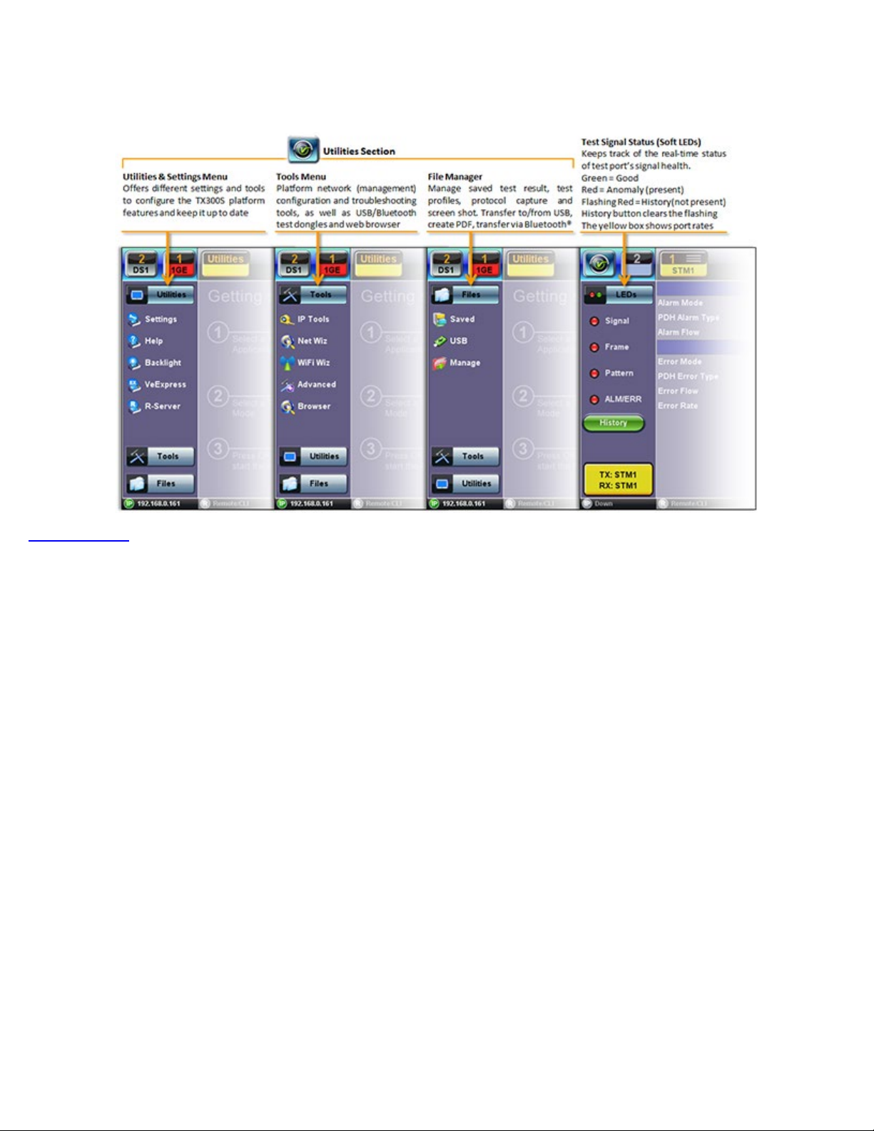
3.6 Quick Access Menu
TX300s_Platform_Manual_RevB00
Page 16 of 104
This multi-tasking section provides convenient and immediate access to system features, connectivity, accessories, results, etc.
Those features are always available, independently of whether tests are running or not.
Go back to TOC
Page 17
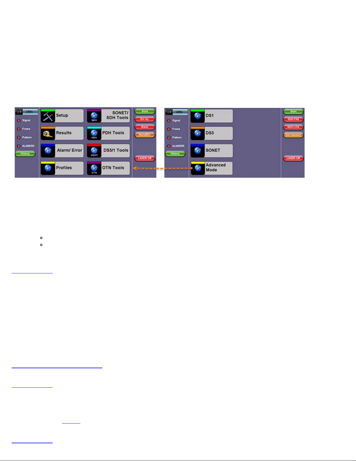
4.0 Getting Started - TX300s
TX300s_Platform_Manual_RevB00
Page 17 of 104
4.1 Initial Settings
4.1.1 Change language and user interface style
Before using the platform, set the language and user interface style as needed. By default, the user interface style is set to USA if
the unit is shipped to North America and to International if the unit is shipped to outside North America.
International user interface style USA Interface style
To change the GUI language and user interface style
1. Tap Utilities, and then tap Settings.
2. Tap the Global option.
3. Select the language from the Language drop-down list box.
4. Select the user interface style from the User Interface drop-down list box.
International: Provides layer-based SDH/PDH configuration menus with access to detailed settings
USA: Provides simplified application-based SONET/DSn menu with more automation. The Advanced Mode option
displays the configuration menu for additional settings
Go back to TOC
4.1.2 Change the time zone and current time
To manually change the Date & Time
1. Tap Utilities, and then tap Settings.
2. Tap the Date & Time option.
3. Select the date and current time from the drop-down list boxes.
4. Tap Apply.
To synchronize the time to the GPS
The GPS receiver hardware option must be installed. For more information on the atomic clock and relative phase monitoring, see
5.1.12 High Precision Clock Source.
Go back to TOC
4.1.3 Change other settings
For more information on changing other global settings, such as units of measurement, profile and results save preferences,
password, etc., see
Go back to TOC
Utilities.
Page 18
4.2 Launching Test Applications
TX300s_Platform_Manual_RevB00
Page 18 of 104
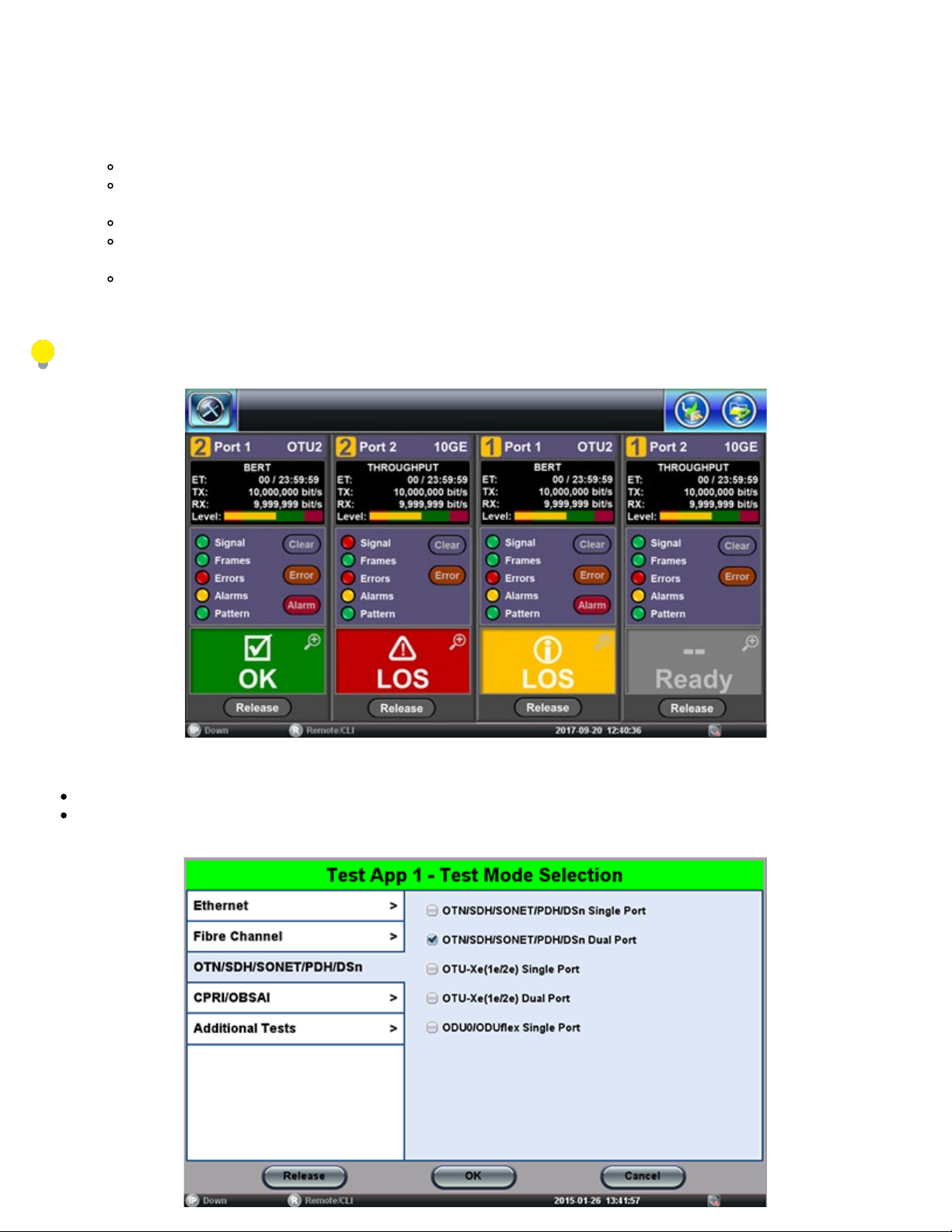
The Test Cards summary/status screen offers intuitive test application management (launch, monitor, switching and release). Each
test card is associated with a test module (orange numbers) and their individual test port groups (white numbers); capable of
showing two, three or four possible tests, depending on the capabilities of the modules installed in the test platform.
Test Cards are aligned in the same order of modules and ports they represent, for easy identification and correlation.
Select the test card related to the desired module and port group, to start a test mode configuration, then follow the
already familiar process.
Use the chassis yellow App rubber button to quickly toggle among the active tests (up to four independent tests).
Use the Test Cards icon, on the top-left corner of the screen, to see a summary of all running tests, available test
resources, switch to a different test (touch on the status box with the magnifying glass icon), and release tests.
Once a new test port group has been selected, using the New button on its Test Card, users can select the specific
test interface type (Test Port), if required. Then the test module will present a menu of all applicable technologies
(protocols) available for the selected port (QSFP-DD, CFP, SFP+, BNC, Bantam, RJ48, etc.)
This procedure can be started at any time, from any screen or menu.
1. Identify an available Test Card (gray) and tap on the New button to launch the Test Mode Selection menu.
Depending on the hardware configuration, up to four tests can run simultaneously.
Some application allocate two test cards or port groups and they are normally available from Port 1 (e.g. router wrap-around
tests, monitoring, etc.)
Page 19
2. Select the Technology Group.
TX300s_Platform_Manual_RevB00
Page 19 of 104
3. Select the desired Test Mode based on the application to be tested.
4. Tap on the OK button to confirm.
The test port group is assigned to the selected test application.
Required software/firmware is loaded.
Go back to TOC
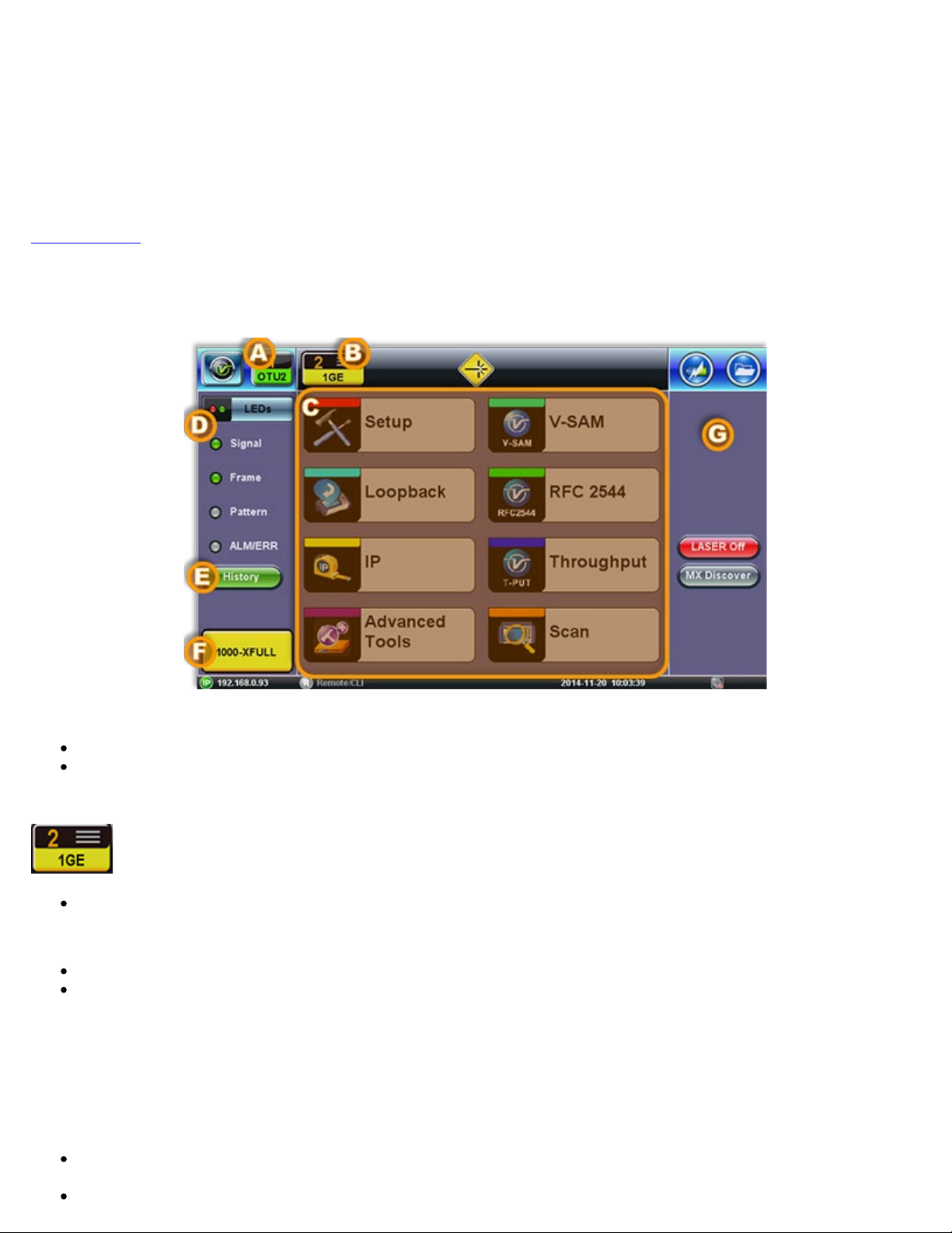
4.3 Understanding Test Application GUI
A. Background Test Application
Tap this button to bring its GUI forward.
Or press the App rubber button to toggle.
B. Active Test Application GUI
- Shows the Test Port Group being used and the Test App ID (Rate / Technology).
Tap this button to release the Test App or change its Test Mode.
C. Test Application Menu
Lists all test Functions, Applications and Tools available for the selected test mode.
Setup = Port and Test Signal configuration.
D. LEDs - Test Signal Status.
E. History - Clears past events reminder (blinking).
F. Current test interface line rates.
G. Action buttons section.
This vertical section displays direct access functions applicable to each specific Test Mode, such as Start/Stop test, Laser
control, Error and Alarm injection, Start protocol capture, etc.
Most of these buttons offer immediate action. A few open a configuration menu.
Page 20
5.0 Utilities
TX300s_Platform_Manual_RevB00
Page 20 of 104
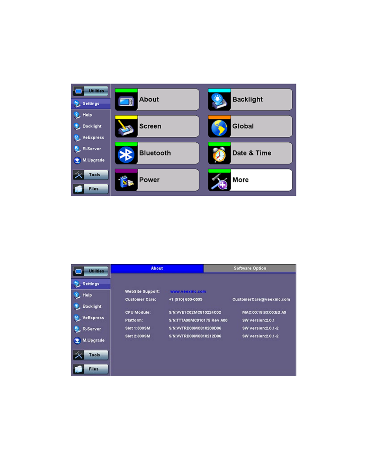
5.1 Platform Settings
This section provides settings for the global parameters of the test set or platform (system settings).
Settings Menu
Go back to TOC
5.1.1 About
This section provides information about the software version, serial number, and MAC address of the management port of the unit,
as well as a list of software licenses (optional test features) currently loaded in the test set.
Utility Settings - About
Page 21
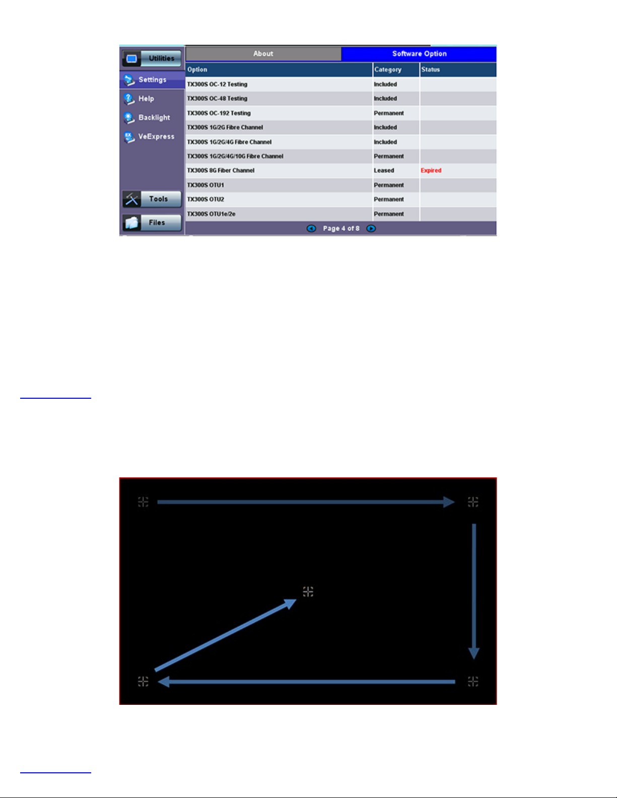
Utility Settings - About - Software Option
TX300s_Platform_Manual_RevB00
Page 21 of 104
Activating New Licenses: Features and options marked as ‘Expired’ (not currently loaded into the test set) can be purchased at
any time and activated via VeExpress using an internet connection. Upon confirmation, connect the test set to the internet via LAN
or Wi-Fi, go to >Utilities >VeExpress and press the Check button. The test set will download all newly added features and options
from VeExpress servers and install them automatically.
If company policy doesn’t allow access to the public internet or the test sets are used within a secured network, users can request
License Keys for manual activation. License keys must be requested at the time new options are purchased. To activate new
features, tap on the expired item and enter the Activation Code that you received from VeEX, VeEX partner or your manager. Press
Activate to complete the licensing process. Each activation code is specific to a test set and a feature. If multiple features are
ordered you would receive individual activation codes for each of them. Manually activated features are specific to a test set and
can’t be shared with other test sets.
Go back to TOC
5.1.2 Screen Calibration
Go to this section to calibrate the touch screen.
Utility Settings - Screen Calibration
Follow the instructions and tap on the center of the five targets displayed at all four corners. A message displays when calibration is
complete. If the touch screen is miscalibrated by mistake, please use the cursor and enter keys to start the calibration feature and
repeat the procedure.
Go back to TOC
Page 22
5.1.3 Bluetooth
TX300s_Platform_Manual_RevB00
Page 22 of 104
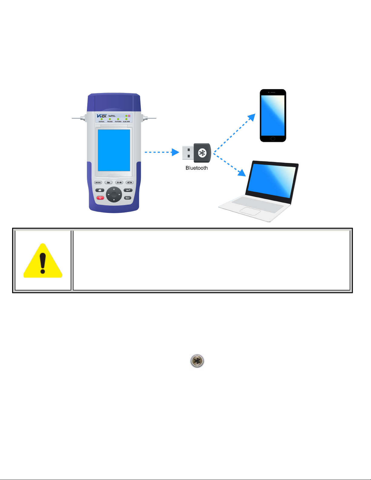
VeEX products support a micro USB Bluetooth adaptor offering wireless connectivity up to 10 meters (30 feet). Ultra compact and
portable, the adaptor provides an untethered connection between the tester and other Bluetooth compatible devices such as a
Notebook PC or cell phone, so the user can transfer test result files quickly and easily without having use memory sticks or Ethernet
connections.
An overview of the application is shown below.
Bluetooth Adaptors - Compatibility
Not all Bluetooth adaptors on the market are supported by the V300 product series. Please use
adaptors that have been tested and supplied by VeEX only to ensure compatibility and correct
operation.
Bluetooth Setup
Insert the Bluetooth adaptor into the USB port on the side of unit. If you are using more than one USB device, use an external USB
hub to connect additional devices. Once detected, a Bluetooth icon
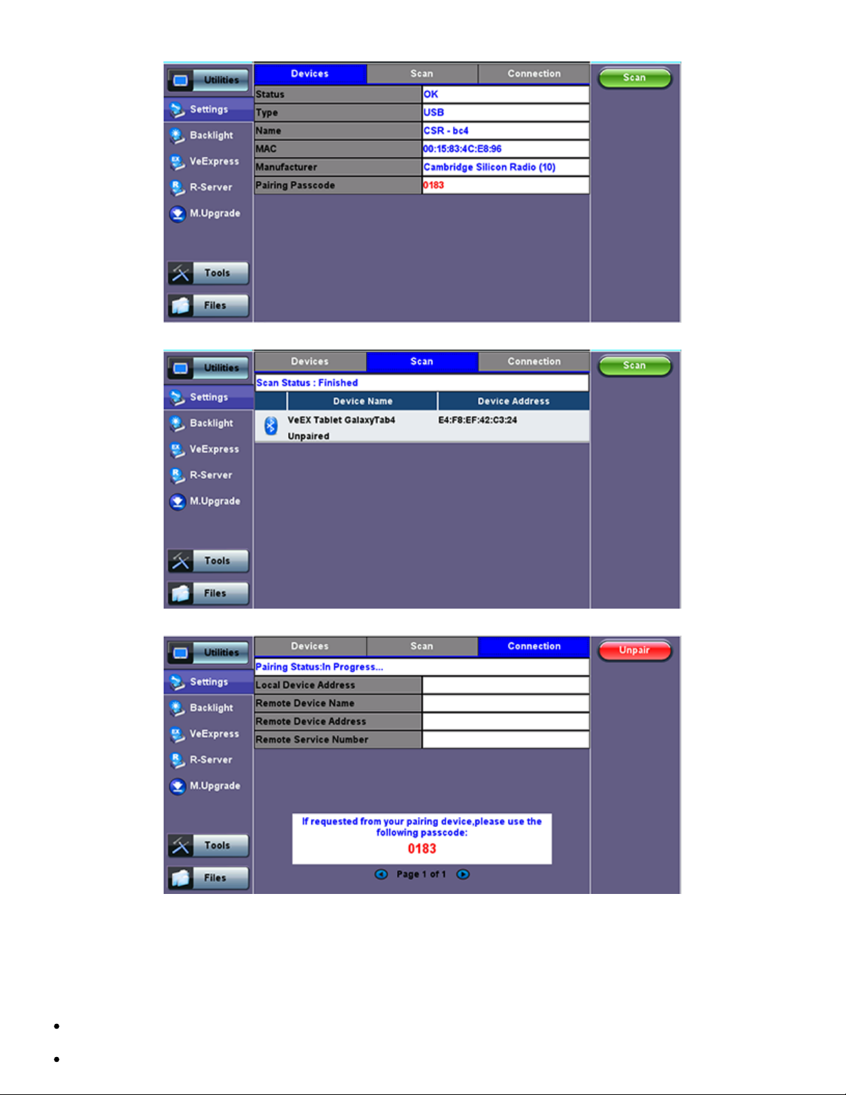
Devices
The test platform will automatically detect the Bluetooth adaptor once plugged into the USB port. Details of the Bluetooth adaptor will
be displayed including the MAC address of the device and the last 4 digits of the serial number of the V300 test set. The last 4 digits
of the V300 series test set will be the pairing code between the unit and the external device. Press the Connection tab to view the
passcode.
is displayed on screen.
Page 23
Bluetooth - Devices Tab
TX300s_Platform_Manual_RevB00
Page 23 of 104
Bluetooth - Devices Tab
Setup
Bluetooth - Connection - Passcode
Press Scan to check for available bluetooth devices. Once scanning is complete, a list of discovered Bluetooth devices will
be listed.
Please ensure the peripheral device is set to Discoverable during Scanning and Pairing operation.
Press Pair BT to begin the pairing process. During the pairing operation, you will be prompted to enter a code on the
Page 24
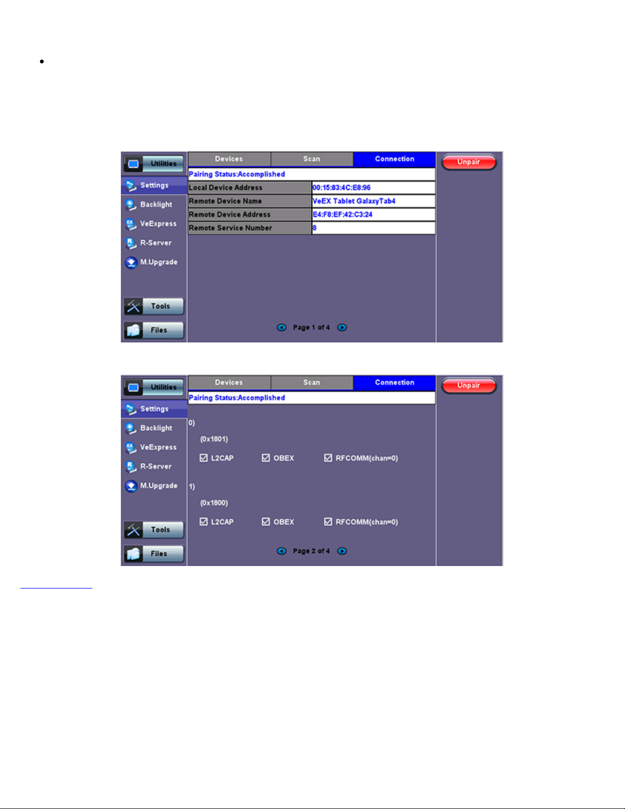
peripheral device (PC or Mobile Phone) in order to pair successfully. Enter the last 4 digits of the V300 serial number as
shown in the Connection tab.
TX300s_Platform_Manual_RevB00
Page 24 of 104
Once paired, click the Services button at the bottom of the screen to check the service attributes. To upload test results via
Bluetooth and Mobile phone to a UMTS or 3G network, full data upload service will be required.
Bluetooth - Connection Established
Go back to TOC
Bluetooth - Connection Page 2
Page 25
5.1.4 Power
TX300s_Platform_Manual_RevB00
Page 25 of 104
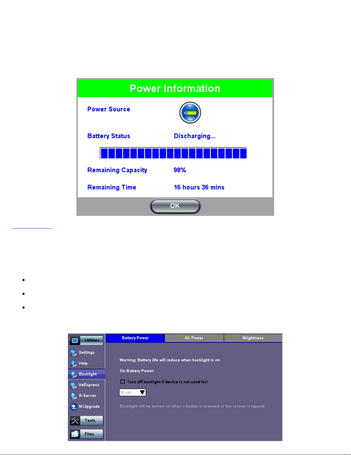
This section provides information about current power source and information about the battery gauge. Tap on the battery icon, on
the top bar, to bring battery charge and estimated autonomy information.
Utility Settings - Battery Power
Go back to TOC
5.1.5 Backlight
This section provides backlight control of the unit.
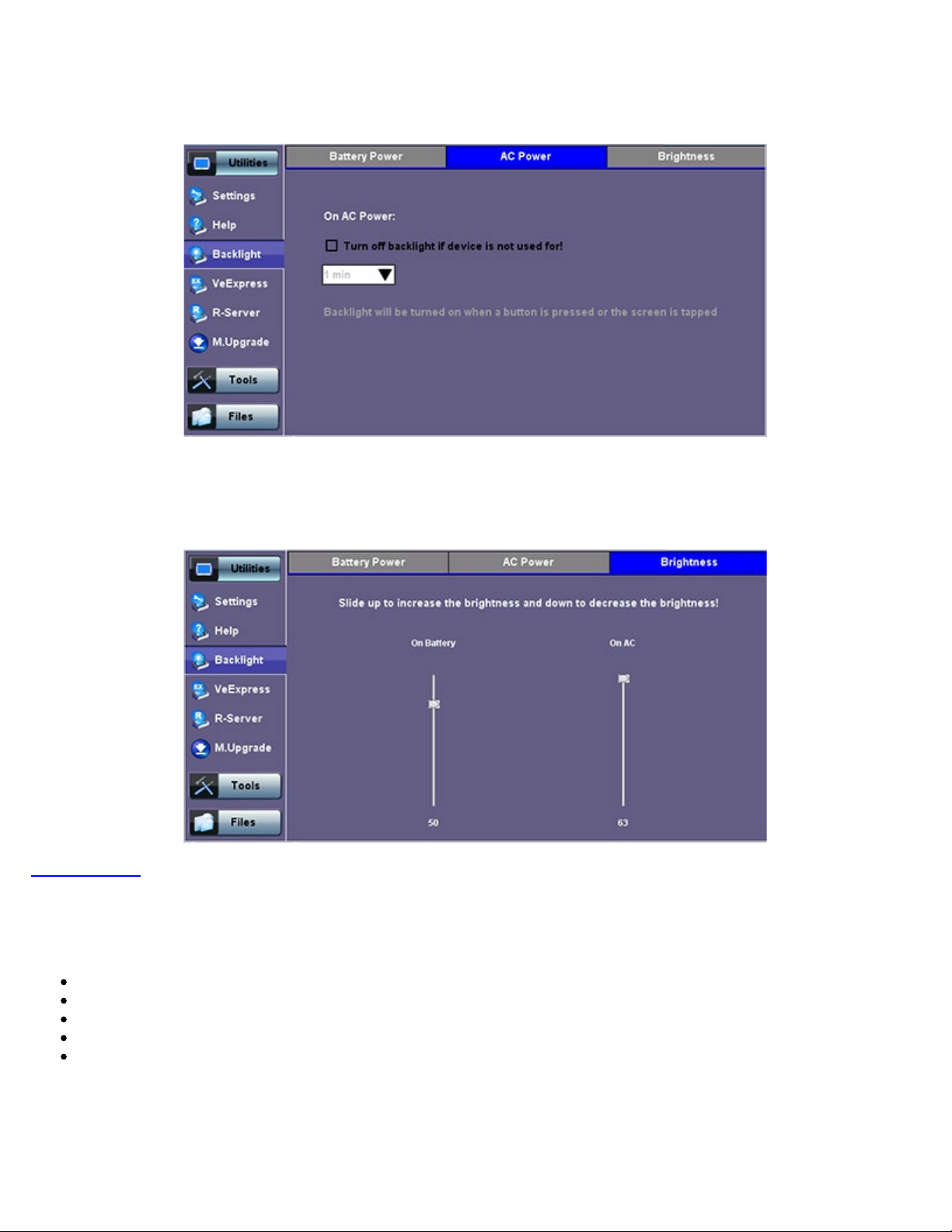
Power: There are two settings -- one for Battery power and another for AC power.
The user has the option to select a timer to turn off the backlight if the unit is not in use. This function helps improve the
battery autonomy and preserve LCD life
To enable the timer, check "Turn off backlight if device is not used for" and with the drop-down menu, adjust the duration
of the idle time before the backlight is turned off.
Once the timer is active and the backlight turned off, any action on the test set (touch screen, keypad) will turn on the
backlight again.
Backlight - Battery Power
Page 26
TX300s_Platform_Manual_RevB00
Page 26 of 104
Backlight - AC Power
Brightness
: The user can select the brightness level for Battery and AC operation modes.
Go back to TOC
5.1.6 Global Settings
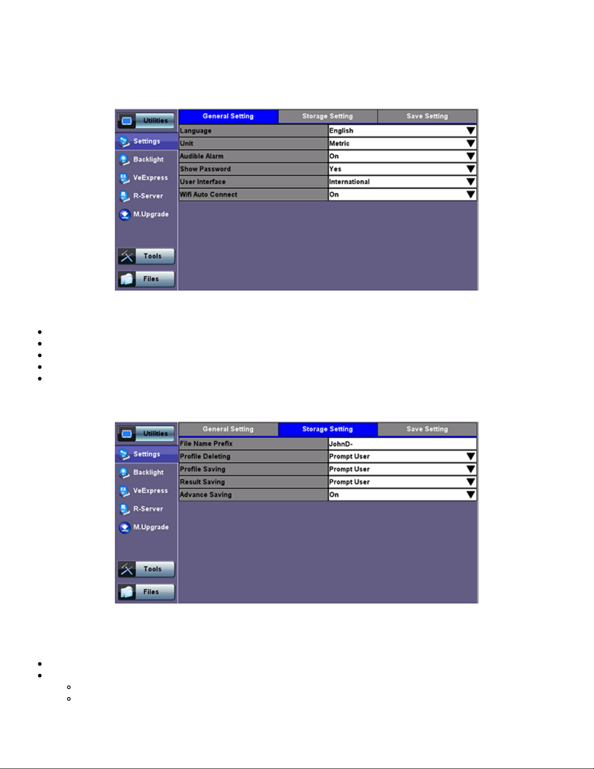
General Setting
Backlight - Brightness
Language: An alternative language for the user interface
Units: Measurement system (English - feet or Metric - meter)
Audible Alarm: When enabled, the test set's buzzer will sound (beep) when alarms and errors are being detected
Show Password: Hides/unhides username and password information associated with FTP and related IP functions
User Interface: The USA user interface version presents SONET/DSn application-oriented menus, while the International
setting is more open to all settings
Page 27
TX300s_Platform_Manual_RevB00
Page 27 of 104
Storage Setting
Utility Settings - General Setting
File Name Prefix: Tap on the box to enter the file name prefix using the pop up alphanumeric keypad.
Profile Deleting: Auto Delete or Prompt User
Profile Saving: Auto Overwrite or Prompt User
Result Saving: Manual or Prompt User
Advanced Saving: On/Off. Allow users to add extra information to the results file to be uploaded to a centralized R300
Server. Requires Advanced Management Option
Utility Settings - Storage Setting
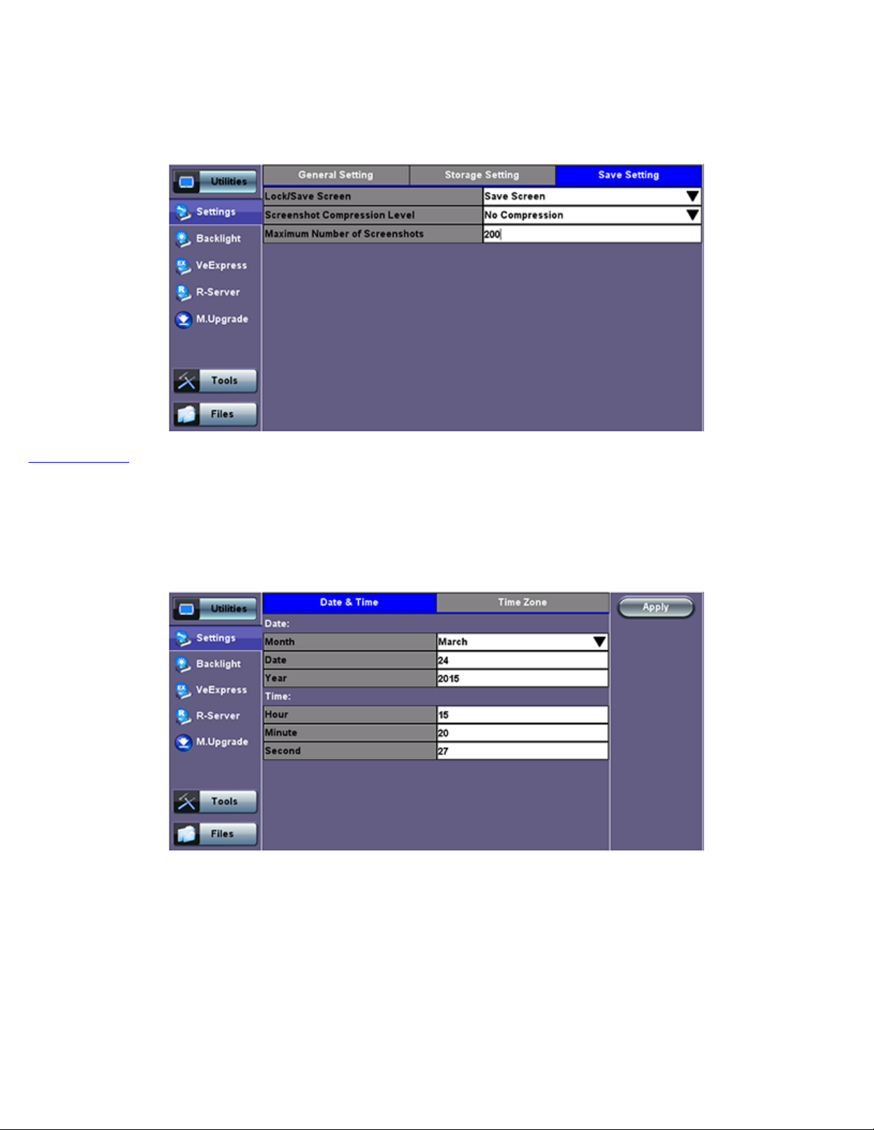
Save Screen Settings
Save Screen tab: Helps control the behavior of the Lock key on the keypad. The Lock key can be set to do the following:
Lock/unlock the unit's screen to prevent accidental interruption during a long term test
Save Screen Shots: The following configurations can also be done:
The compression level of the screen picture
Maximum number of screenshots that can be saved
Each time user presses the lock key from the key pad a screen shot will be saved in memory. The screen shots can be
recovered under Files>Saved.
Page 28
TX300s_Platform_Manual_RevB00
Page 28 of 104
Go back to TOC
Utility Settings - Lock/Save Screen
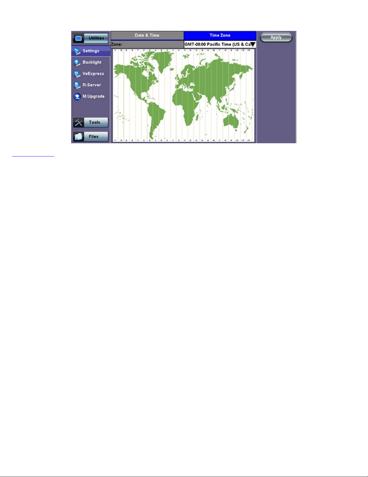
5.1.7 Date and Time
This screen allows the user to set the date and time according to time zone or user requirement. Daylight savings are automatically
enabled in the utility.
Date Setup
Page 29
Go back to TOC
TX300s_Platform_Manual_RevB00
Page 29 of 104
Time Zone Setup
Page 30

5.1.8 Remote Access
TX300s_Platform_Manual_RevB00
Page 30 of 104
There are different ways to control or access the test set and the information it contains, from a local (LAN) or remote (WAN)
connected PC:
ReVeal PC software
VNC Client
Web Browser
VeEX SCPI Remote & Command Reference Tool (PC software, requires separate licensing)
Using command line interface (CLI) scripts via SSH connection
ReVeal RXTS PC software
This VeEX application allows users to connect to the test set, using the platform’s IP address. ReVeal intuitive user interface offers
the following functions:
Test Profiles Management: Create, Edit, upload and download complex Ethernet and Fibre Channel test profiles (BERT,
Throughput, RFC2544, Y1564 SAM, Scan, IP, Ping/Trace, Packet Capture, etc)
Test Results Management: Download results from the test set, manage local test results (PC HDD), generate detailed test
reports, export to CSV or PDF, and print
View software options, licenses, serial numbers
ReVeal is a Windows® application that can be downloaded free of charge from
www.veexinc.com.
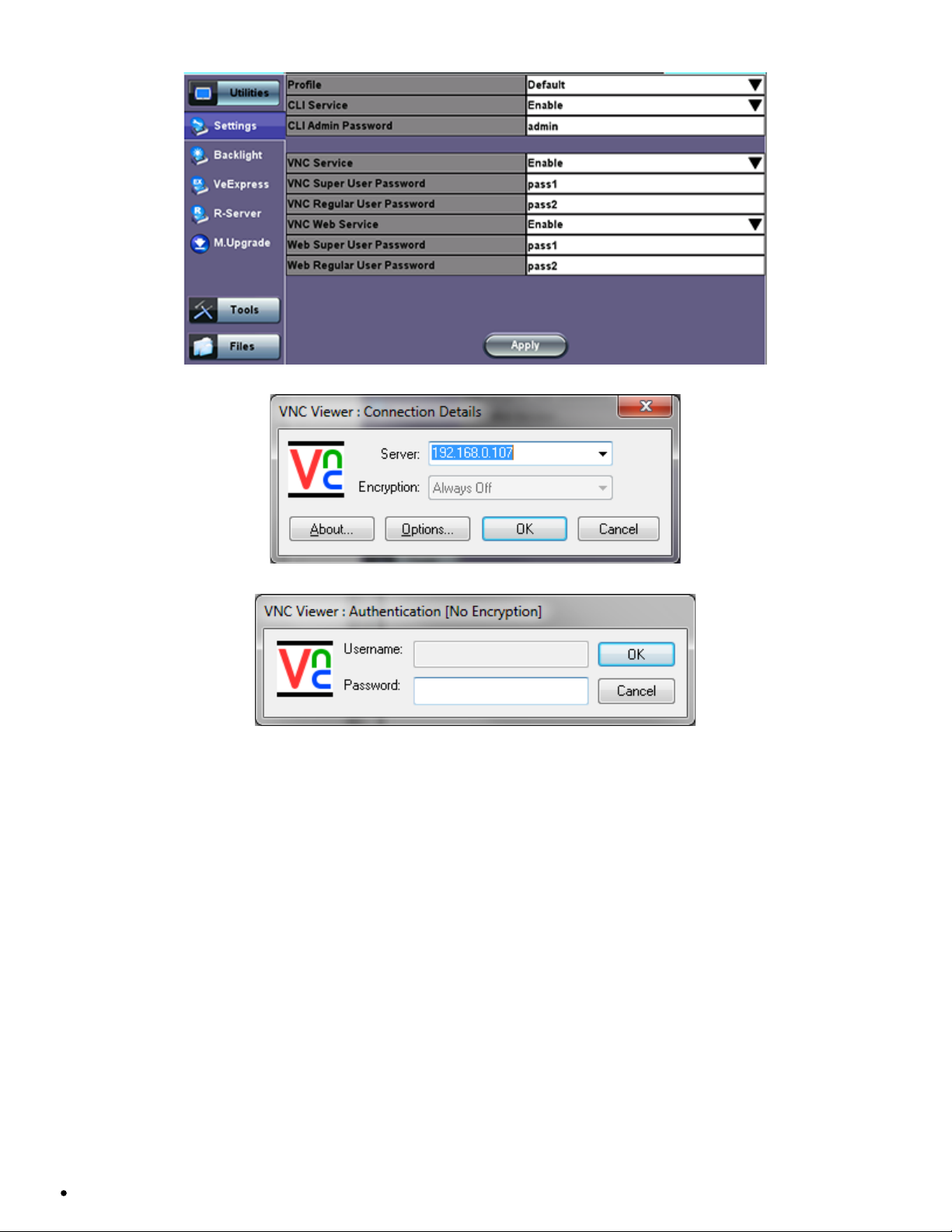
Users are able to connect remotely from a desktop PC via ReVeal tool software or through Remote Access on the test set. To
proceed with remote access, make sure that remote control software is installed on the PC device. The user is able to configure the
Profile, VNC Server Service, Web Service, VNC and Web passwords on the Remote Access page. Input the test set IP address and
specified user password when prompted by the software to initiate Remote Access.
For more details, see the ReVeal RXT user manual on
www.veexinc.com.
Remote access with VNC Server/Viewer:
The test set VNC service can be managed in >Utilities >Settings >More >Remote Access menu, to enable or disable the VNC
server and assign remote access passwords.
Super User Password: Allows remote VNC clients to view and control the user interface via mouse
Regular User Password: Allows remote VNC users (guests) to view what’s currently on the test set screen, but no
interactions with the GUI are allowed
Although the test set VNC services allows multiple users to be connected simultaneously, it is a screen mirroring service, so all
users would be seeing and interacting with the same GUI. Such feature can certainly be used for training purposes, but it is not
recommended for multi-user or multi-test environments.
VNC clients, such as RealVNC®, are readily available for download for different platforms and form factors, including Windows®.
Mac OS®, Linux, iOS, Android.
VNC Service: Enable or disable the remote access to remote VNC clients running on PCs, Macs, tablets or smart phones
VNC Super User Password: Defines the password for users allowed to control the test set via standard VNC clients
VNC Regular User Password: Defines the password given to users who are only allowed to view the test set current screen
via standard VNC clients, but not make any changes to test or test set
After configuring these settings in the Remote Access menu, run VNC on the PC. A message box will prompt the user to enter a
Server number, which is the test set IP address. Enter the VNC Super/Regular password when prompted by the message box for a
password.
Page 31
Remote Access
TX300s_Platform_Manual_RevB00
Page 31 of 104
VNC Viewer - Enter Server Address
VNC Viewer - Password Prompt
Remote access via web browser:
Java-enabled web browsers, such as Internet Explorer™, Chrome™, FireFox™ or Safari™ can be used to manage the test set,
access information and remotely control it. This useful feature doesn’t require the installation of any remote clients, other than the
standard web browser. Just enter the test set’s IP address in the browser address/search field and the web GUI will launch.
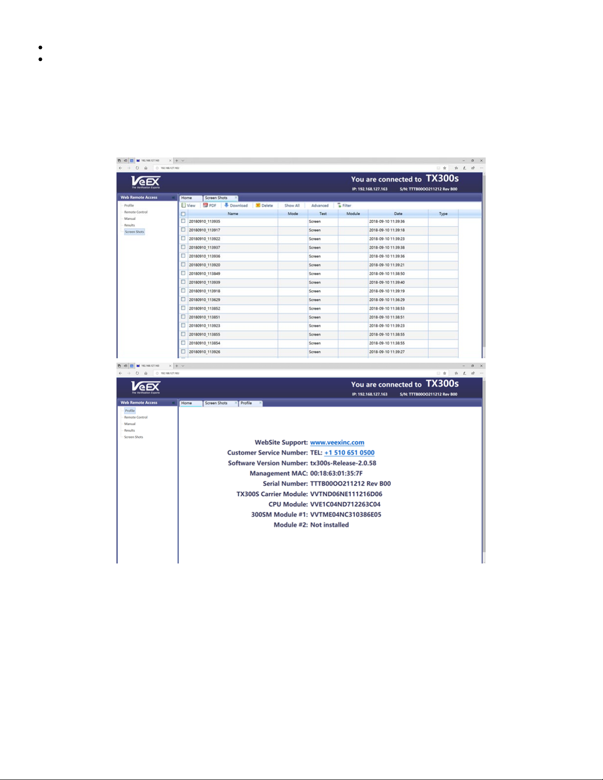
The following features are supported:
Profiles
Use this function View, Download, Delete, Filter and convert saved Test Profiles to PDF
Manuals
Access soft copies of the TX300s platform and modules manuals for quick reference
Results
Use this function to View, Download, Delete, Filter and convert saved Test Results to PDF
Screen Shots
View, Download (PNG format), Copy, Delete and convert to PDF any screens captured using the TX300s Lock button
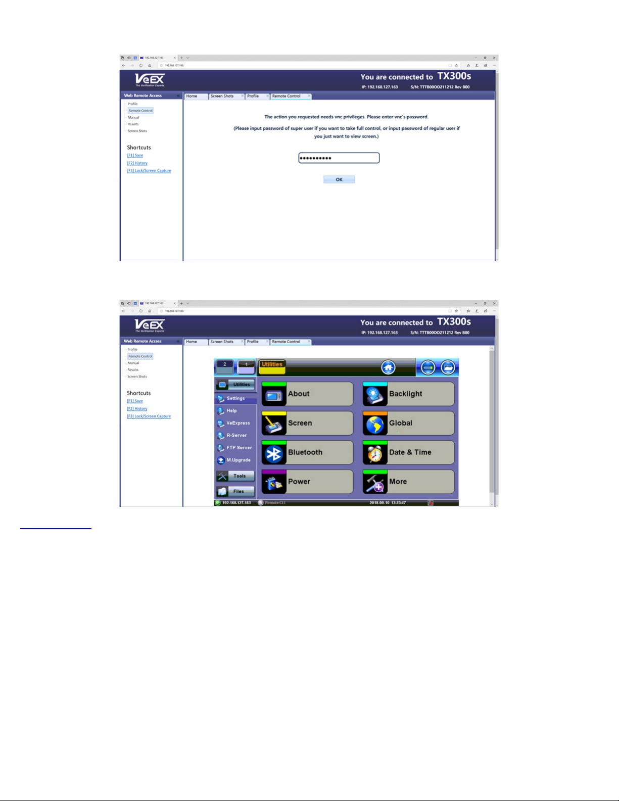
Remote Control (Screen Mirroring)
It is similar to using VNC, but in this case no VNC client installation is required. It uses a standard Java-based web browser as a
client. It mirrors the screen, mouse inputs and the rubber buttons available in the front panel of the test set.
VNC Web Service: Enable or disable the remote access through remote web-browser clients running on PCs, Macs or
Page 32
certain tablets. The web browser must support Java (tm)
Web Super User Password: Defines the password for users allowed to control the test set via standard web browser clients
TX300s_Platform_Manual_RevB00
Page 32 of 104
Web Regular User Password: Defines the password given to users who are only allowed to view the test set current screen
via standard web browser clients, but not make any changes to test or test set
Type in the test set IP address in the web browser. Click on vnc-home.html and type in the Super/Regular password when prompted
for a password. Use the buttons and icons on the right to navigate the test set remotely.
Test Set IP Address in Web Browser
Page 33
Web Browser - Password Prompt
TX300s_Platform_Manual_RevB00
Page 33 of 104
Web Browser - Remote Access Menu
Go back to TOC
5.1.9 EZ Remote
The EZ Remote
functionality allows users to quickly and securely connect to VeEX test sets all over the world, without the need for
VPN, port forwarding or public IP addresses. This VeEX hosted service and user interface take care of all the complex tasks
required, and present users with a simple application. Connect online anytime anywhere with any computer, tablet or smartphone,
using standard web browser clients for screen-sharing, remote control and access to test results. Use it for remote control,
collaboration, technical support or training purposes.
Page 34
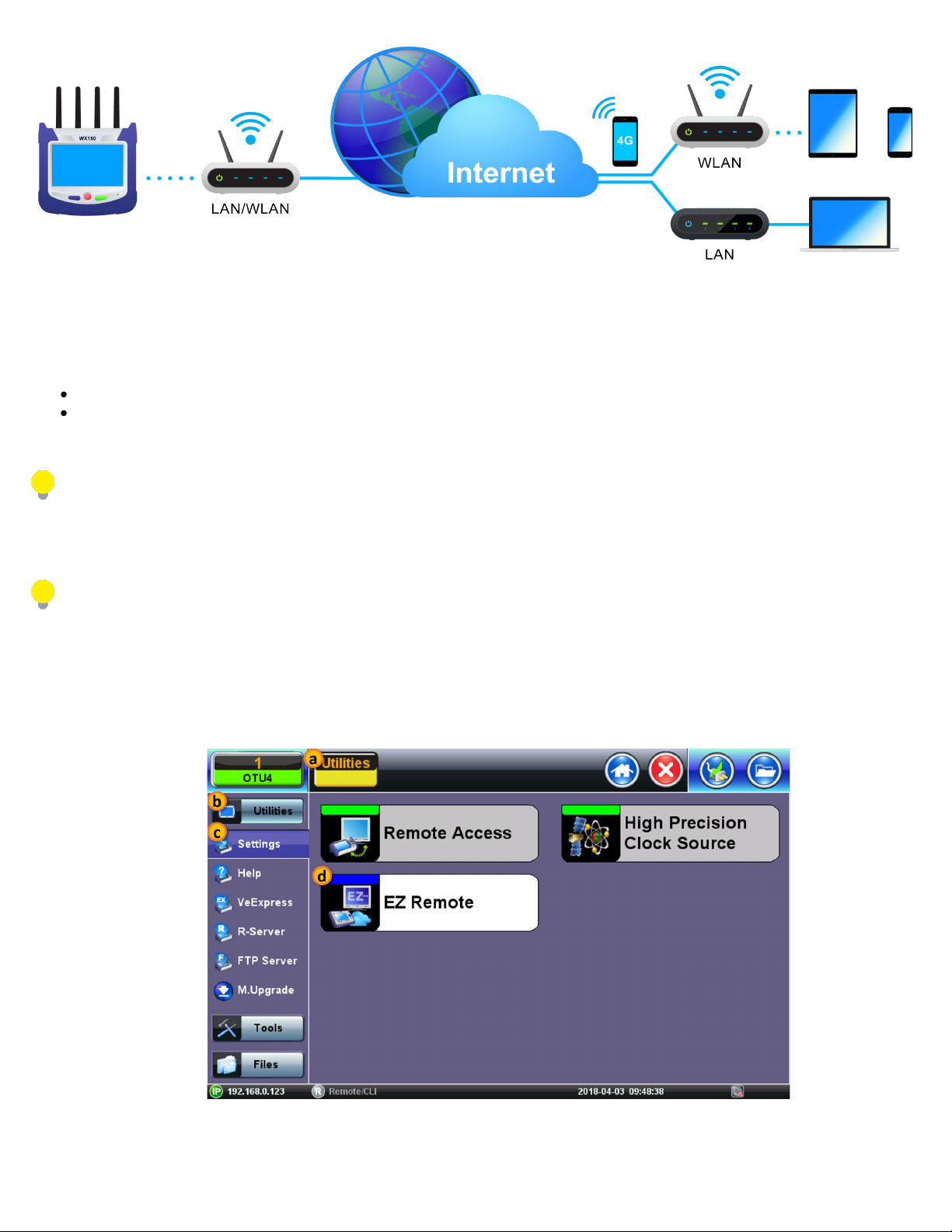
The basic EZ Remote service is offered by VeEX free of charge. It provides public registration servers to help users and test sets
TX300s_Platform_Manual_RevB00
Page 34 of 104
stablish remote sessions, without having to get IT departments involved. All you need is internet access for the test set and a remote
user. Feature location and functionality may vary from product to product.
VeEX’s EZ Remote provides:
Remote Control functionality to give users full control of remote test sets (screen mirroring and control).
Remote Access functionality allows users to View, Download, Rename, Delete, Export and Convert results (PDF).
Feature location and available functions may vary from product to product.
EZ Remote is considered a convenient on-demand service, for quick/temporary collaboration tasks. It should not be used for
long-term applications (VeEX offers other remote tools for long-term applications.)
Initiate an EZ Remote Session from the Test Set
Not all VeEX test sets may offer EZ Remote functionality. Make sure to upgrade to the latest versions available.
1. Use the >Utilities >Tools >IP Tools to connect the test set to a LAN using the RJ45 Ethernet management port, located on
the side of the unit (recommended), or use WiFi Wiz to connect to a WLAN (using built-in Wi-Fi or a compatible external USB
dongle). Make sure the test set gets a local IP address and that the LAN/WLAN provides access to the public internet (web).
2. Go to >Utilities >Settings >More >EZ Remote.
3. On the EZ Remote screen, set
on Apply to connect and establish a session with the EZ Remote server.
EZ Remote to Enabled, confirm the URL is ezremote.veexinc.net (without www.), and tap
Page 35
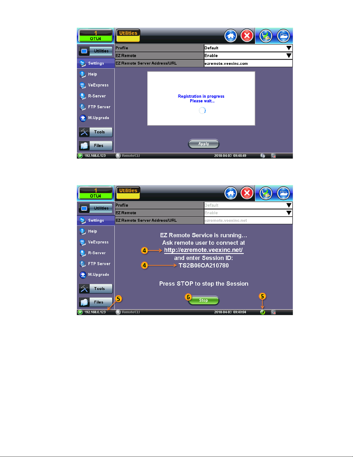
4. Provide the resulting URL and Session ID to the intended remote user.
TX300s_Platform_Manual_RevB00
Page 35 of 104
5. You may continue to use the test set until a remote user logs in, then both will share control over the unit. Make sure the test
set remains connected to the LAN/WLAN/Internet and that the
green.
6. When finished, use the Stop button to terminate the EZ Remote session and disconnect from the server.
EZ remote session indicator at the bottom of the screen stays
Page 36
TX300s_Platform_Manual_RevB00
Page 36 of 104
Connect to the Remote Test Set from a Computer
Establish a Remote Access Connection
EZ Remote provides two types of services:
Remote Control (screen and mouse/touch mirroring) to operate a test set from a different location
Remote Platform Access to access information stored in the remote test set, such as Test Results, Profiles, User Manual,
Screen Captures (screen shots), information about the test set (Home) and its local IP address
Although multiple users could simultaneously log-in to the same test set, they would be sharing the same mirrored GUI image
and mouse control. This is not recommended since it is equivalent to having multiple users trying to operate one test set at the same
time (also known as “mouse fight”). Nonetheless, it may be effective for training purposes with one or two extra users.
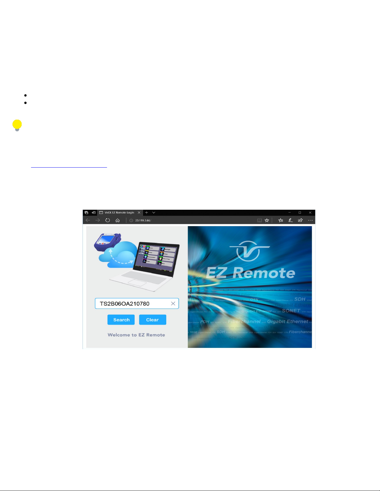
1. From a PC, Mac, Tablet or Smartphone
launch an industry-standard Web Browser application and enter the URL
http://ezremonte.veexinc.net. (without the www.). Enable pop-ups for your browswe and be sure to authorize access to the
site, if confirmation is requested by the browser or OS.
2. Enter the >Session ID provided, making sure not to confuse zeroes (0) with Os. Click on Search to find the target test set
and stablish a peer-to-peer connection.
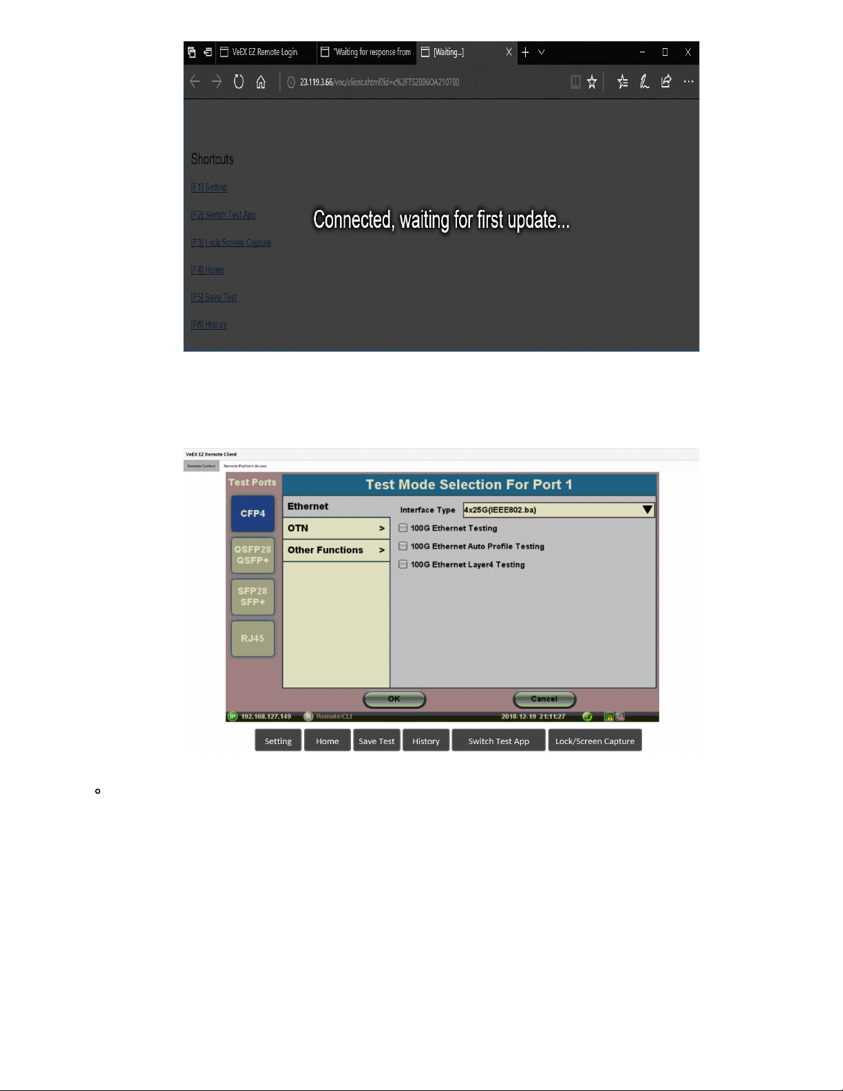
3. Once verified and connected, wait for the remote user interface to refresh. This may take a few seconds.
Page 37
TX300s_Platform_Manual_RevB00
Page 37 of 104
4. Depending on the type of test set used, shortcut buttons may be provided below the mirrored screen, allowing access to
functions provided by physical buttons on the instrument, such as
Settings, Home, Save Test results. Click or tap on the
shortcut to activate it.
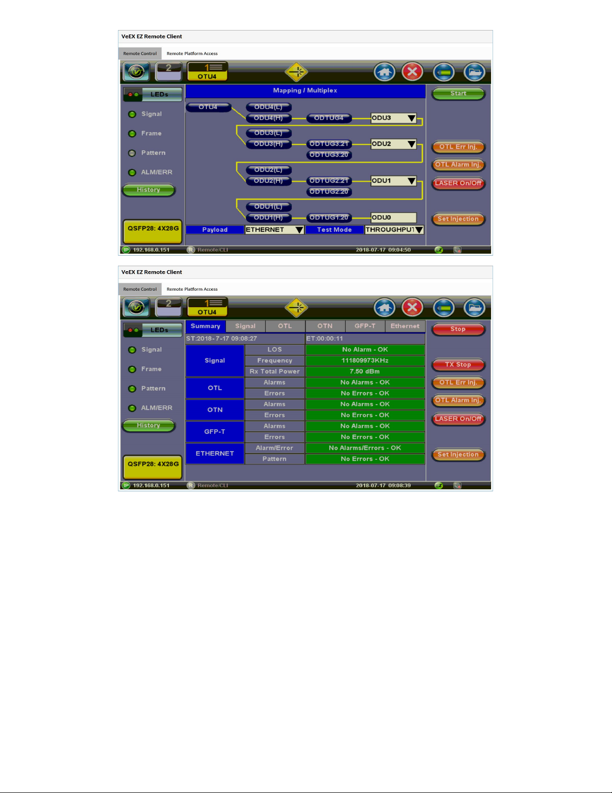
Once the remote GUI appears, you can use the Remote Control tab to operate the test set in the same way you
would control a local unit from its touch screen.
Page 38
TX300s_Platform_Manual_RevB00
Page 38 of 104
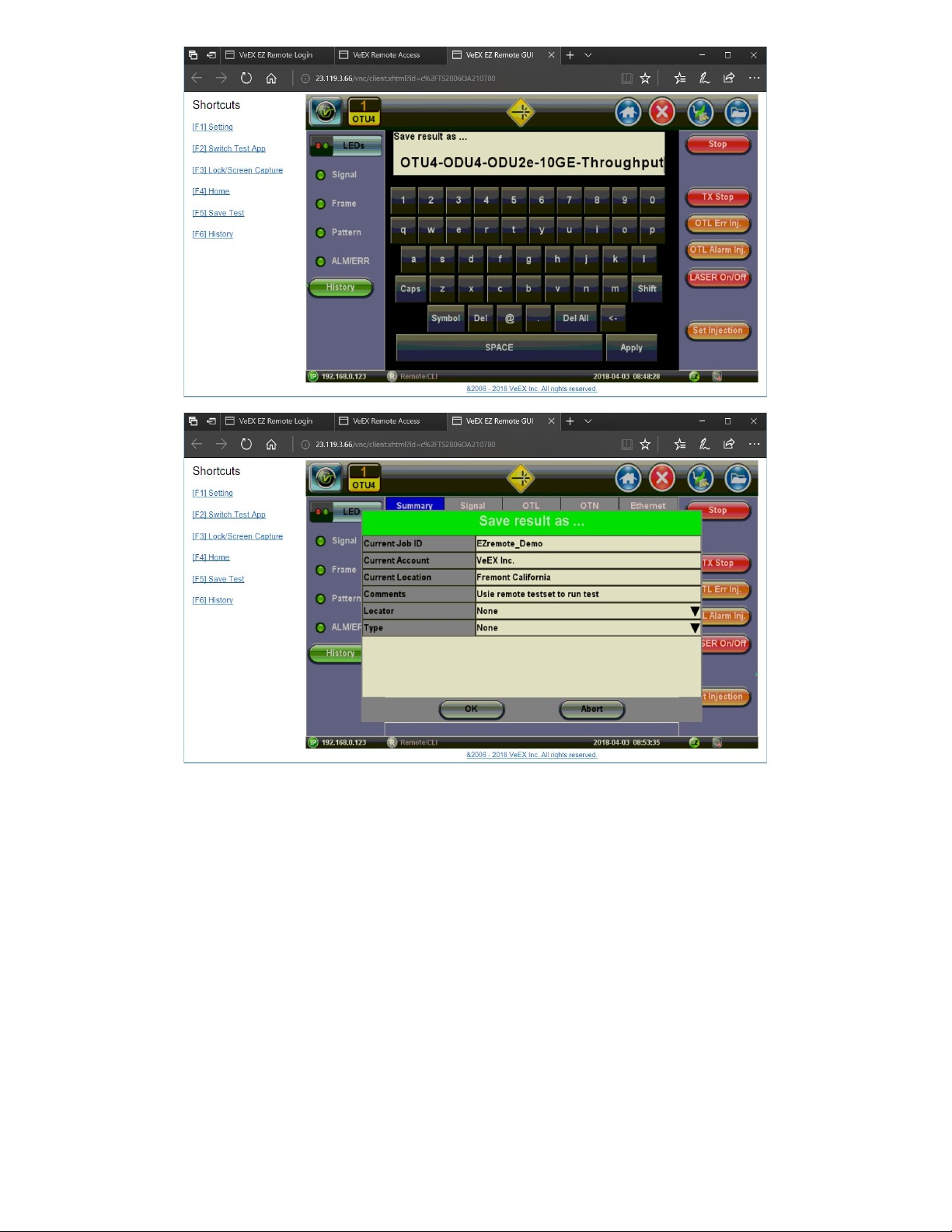
Save Test Results
To save the results of a test, from the remote computer, press the Save button below the screen image. Then use the pop-up
keypad and/or the PC keyboard to enter the file name and add any extra details (if Advanced Save is enabled).
Page 39
TX300s_Platform_Manual_RevB00
Page 39 of 104
Access Remote Test Result Files
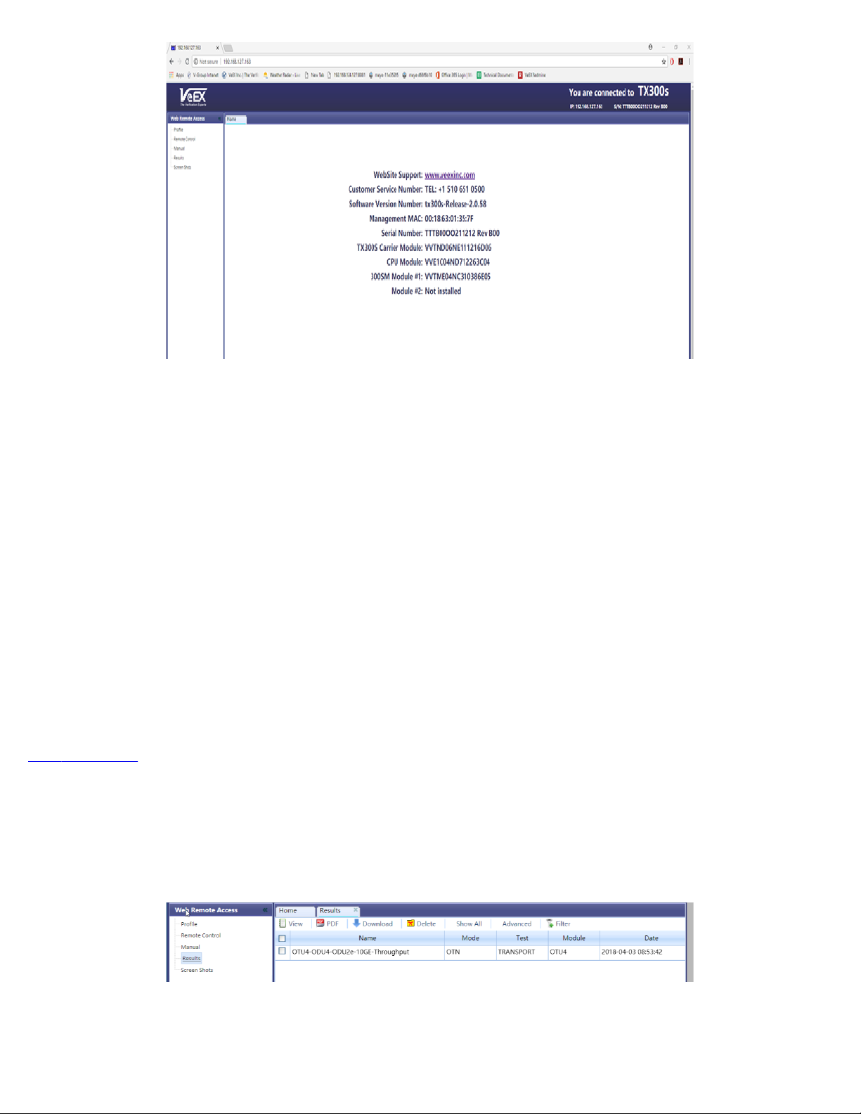
The Remote Platform Access tab
information stored in the test set.
provides links to access test results, test profiles, screen shots, the user manual and other
Page 40
TX300s_Platform_Manual_RevB00
Page 40 of 104
A tab will open up for each selection made, allowing for quick access to each fuction.
Pofiles
Test Profiles
are configurations saved by the user that can be retrieved and reapplied to the test set. For example, commonly used
configurations and test limits/threshold can be saved as test profiles, for different types of services.
Remote Control
Remote Control has been replaced by EZ Remote tab.
Manual
The feature provides access to the user manual that is built into the test set. In this application, the use of a local copy of the PDF
file is reccommended as the PDF client in the local computer is most likely faster than accessing the remote one and may offer
better tools and fuctions, including search capabilities. User manuals can be downloaded from the products’ page at
www.veexinc.com.
Results
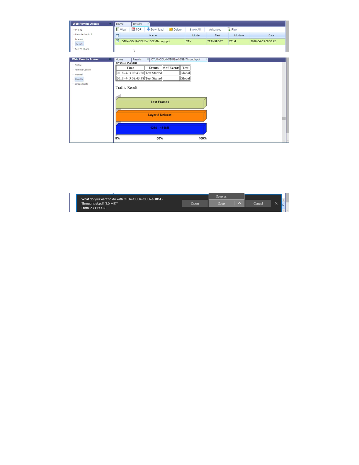
Results list all the test results files currently stored in the remote test set. Users can View
, Rename and Delete files stored in the
remote test set, as well as Download selected files to the local computer or convert them to PDF and download.
To open a test results file, select it from the list and tap on View.
Page 41
TX300s_Platform_Manual_RevB00
Page 41 of 104
Files can be downloaded by clicking on Download (original file format) or PDF.
Screen Shots
Pictures (PNG) taken of the screen can be accessed from this link and sub-tab. Pictures can be viewed or downloaded to the local
computer.
Screen captures can be made using the Lock button (Ï
) on the test set or from the remote computer, using the links provided or the
respective F-key on the computer’s keyboard. The screen capture function can be enabled in >Utilities >Settings >Global >Save
Settings.
5.1.10 VF Noise Calibration (Microphone)
The test platform offers ambient audio Noise Reduction for its built-in microphone, to improve voice quality in Voice Frequency (VF)
applications like ISDN and VoIP calls. The microphone noise reduction function is enabled, in >Utilities >Settings >Global
>General Settings >Mic Noise Reduction = ON,
Page 42
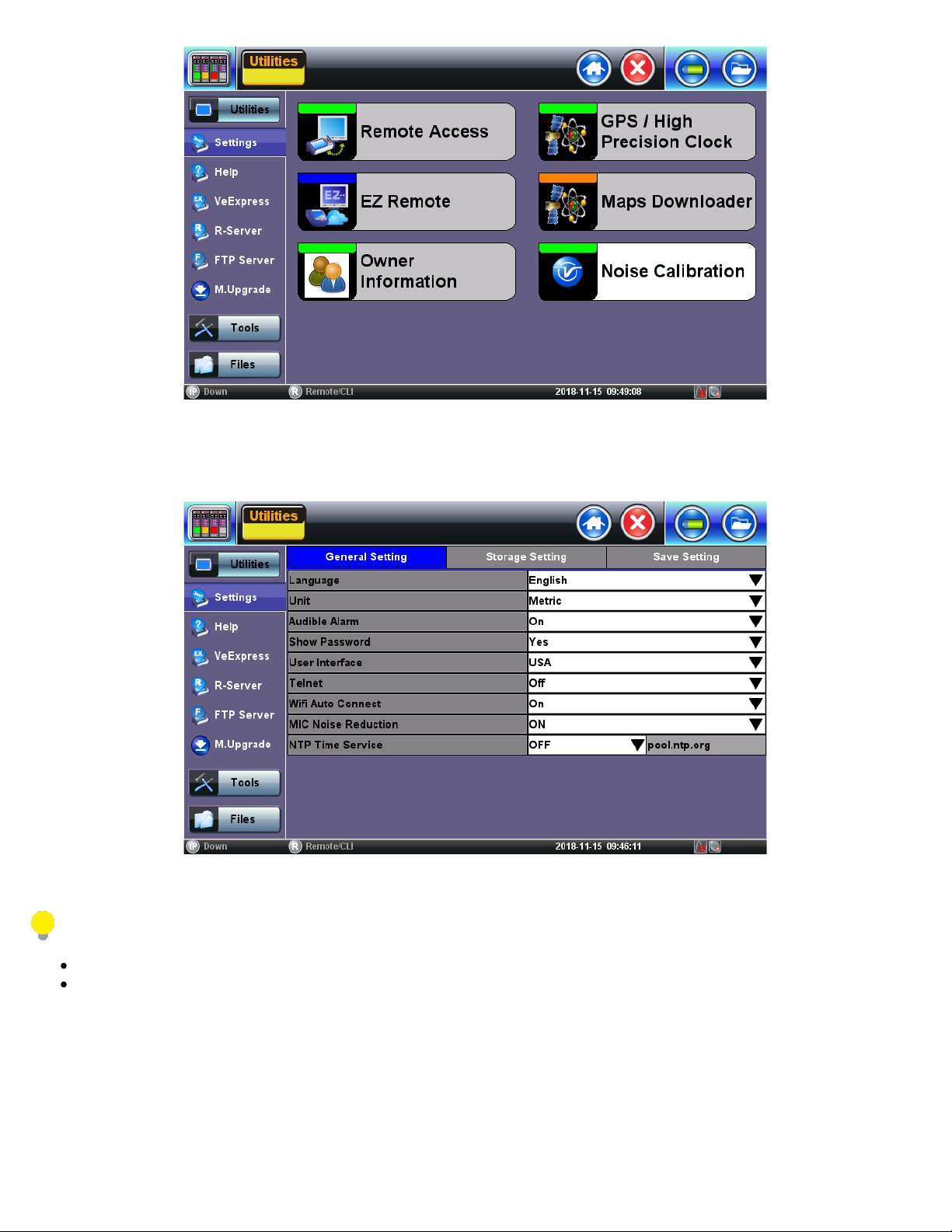
Users can calibrate it to remove typical environmental noise and improve voice quality. The test set must be recalibrated before use
TX300s_Platform_Manual_RevB00
Page 42 of 104
and when moved to a different environment (e.g. from the equipment room to an office). The Noise Calibration function can be found
in >Utilities >Settings >More >Noise Calibration.
Stay silent while the calibration is in progress.
If a headset is used for ISDN or VoIP calls, it must be plugged in during the calibration process.
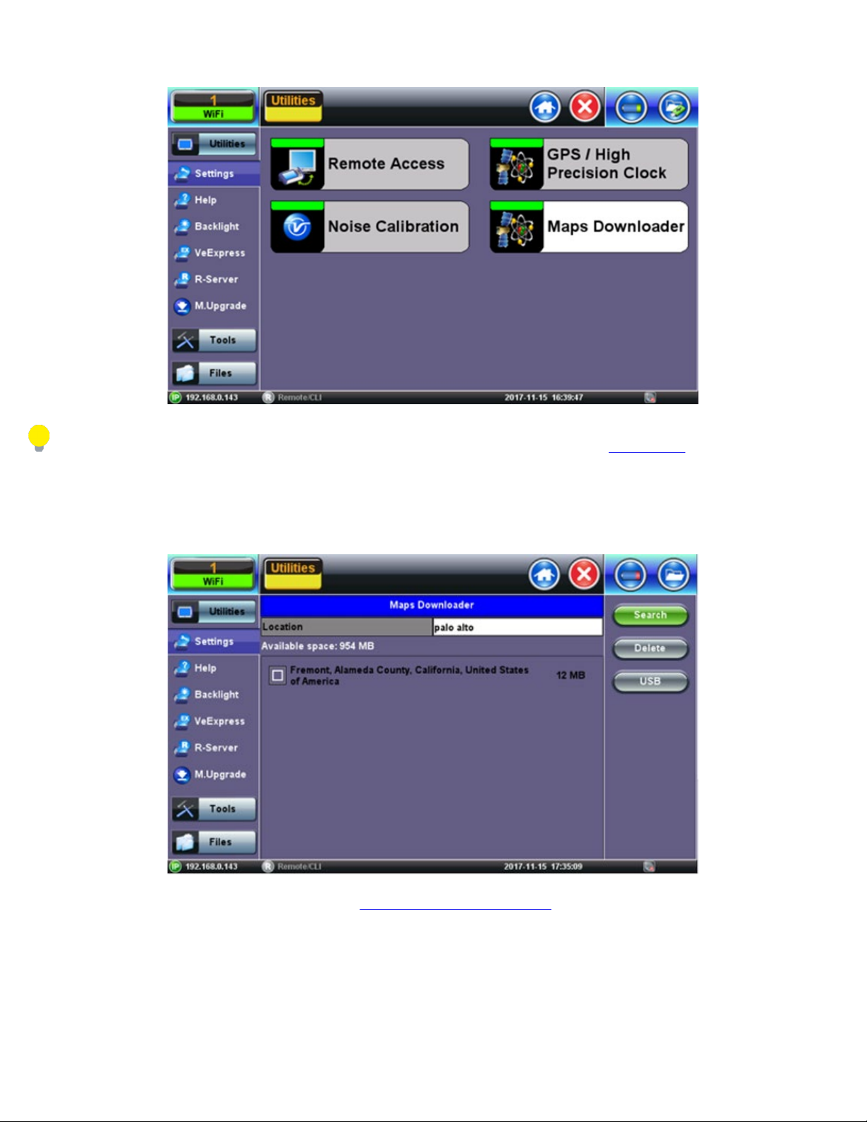
5.1.11 Maps Downloader
The Maps Downloader can be found in the Utilities section, under >More >Maps Downloader.
Page 43
Maps Downloader
TX300s_Platform_Manual_RevB00
Page 43 of 104
This function requires management port connection (Ethernet or Wi-Fi). Please see section 7.1 IP Tools for further information
on how to connect via the managment port.
1. Enter the city name in the search box.
City Location
The unit connects automatically to the database here: http://www.openstreetmap.org/. Open Street map is similar to Google maps,
but the maps are open source and created by a community of cartographers that contribute and maintain data about roads
worldwide.
2. Select map from the list and tap on the Download button.
Page 44
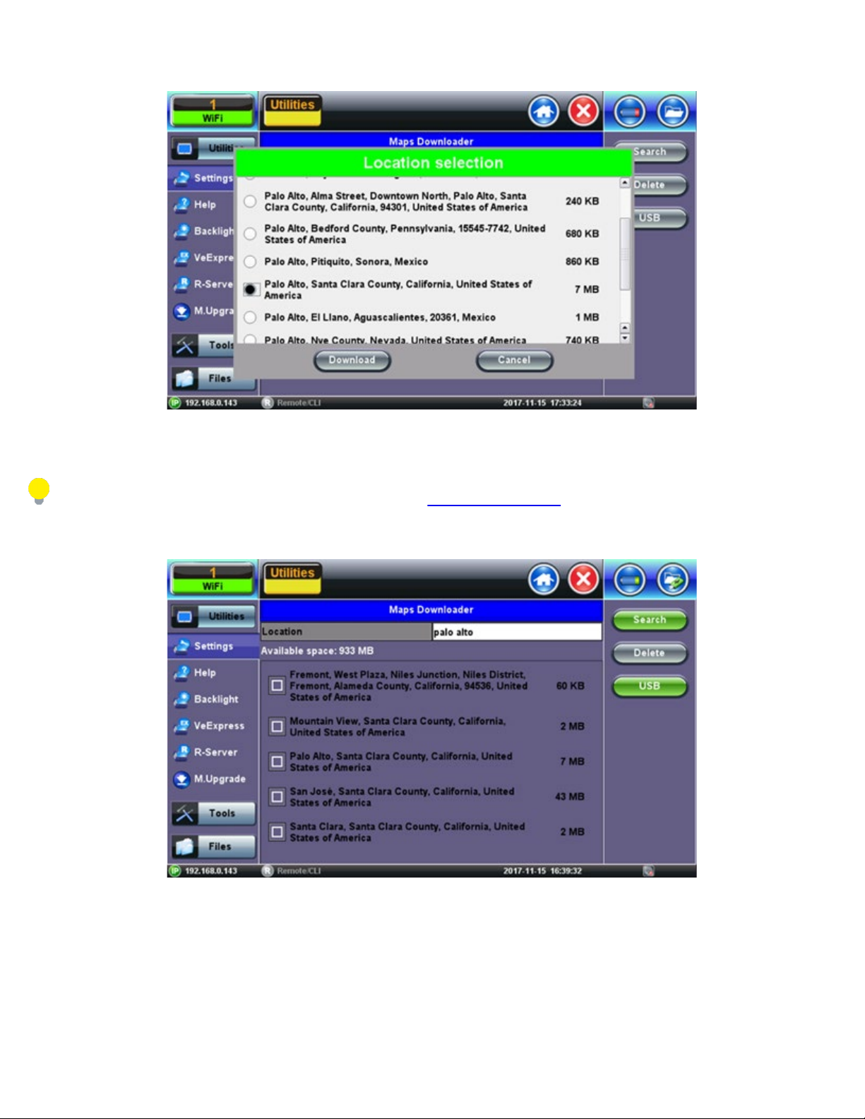
Select Map
TX300s_Platform_Manual_RevB00
Page 44 of 104
After downloading the map, the unit shows a list of all the downloaded maps. Maps can also be deleted or transferred to and from a
USB stick.
For further instruction on USB file transfer please see chapter 6.0 File Management.
Downloaded Map
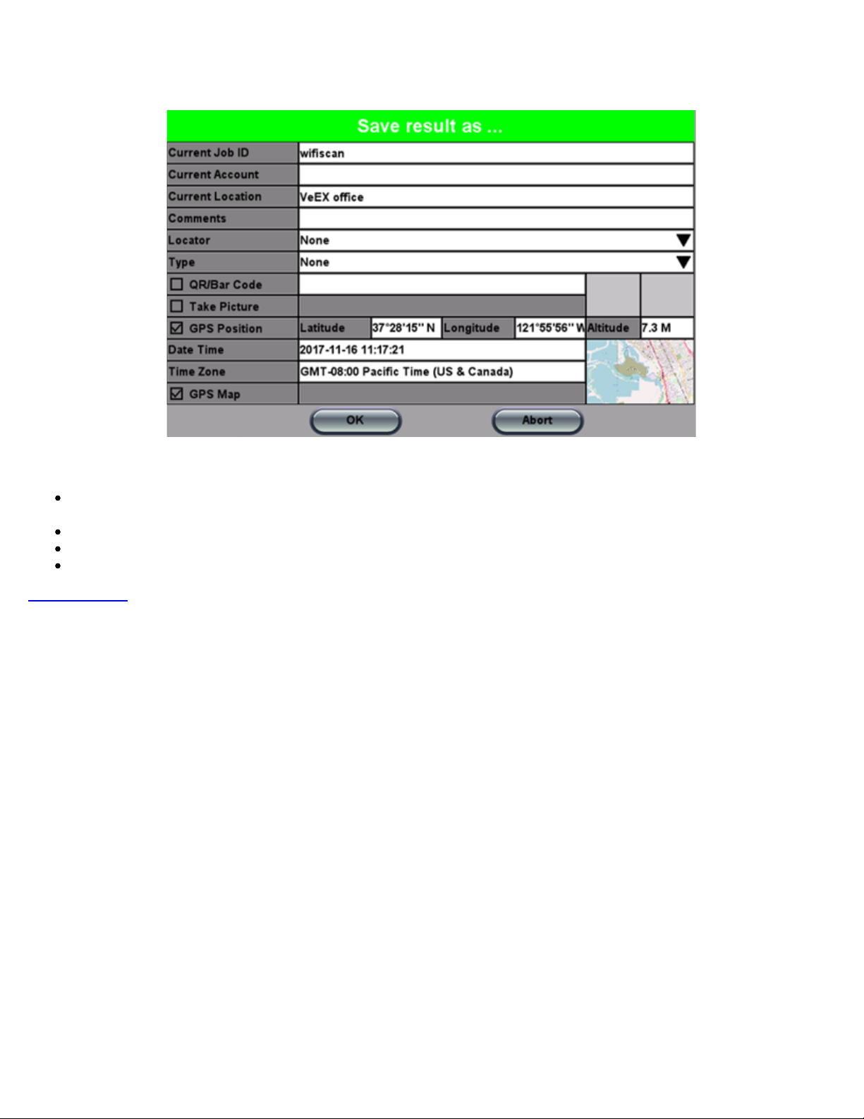
Maps are included if Advance Saving function is enabled (Utilities>Settings>Global>Storage Setting) and GPS position is
acquired (Utilities>Setting>More>GPS/High Precision Clock).
Page 45
TX300s_Platform_Manual_RevB00
Page 45 of 104
Save Results
Equipped with a camera and GPS antenna, the MTTplus platform allows to create a complete report of the Wi-Fi site survey
results in HTML or PDF format.
QR code reader to document equipment bar code and serial numbers.
Camera function to document the AP location and installation.
GPS Coordinates to identify test location and map.
Go back to TOC
Page 46
5.1.12 High Precision Clock Sources
TX300s_Platform_Manual_RevB00
Page 46 of 104
Precision Clock References
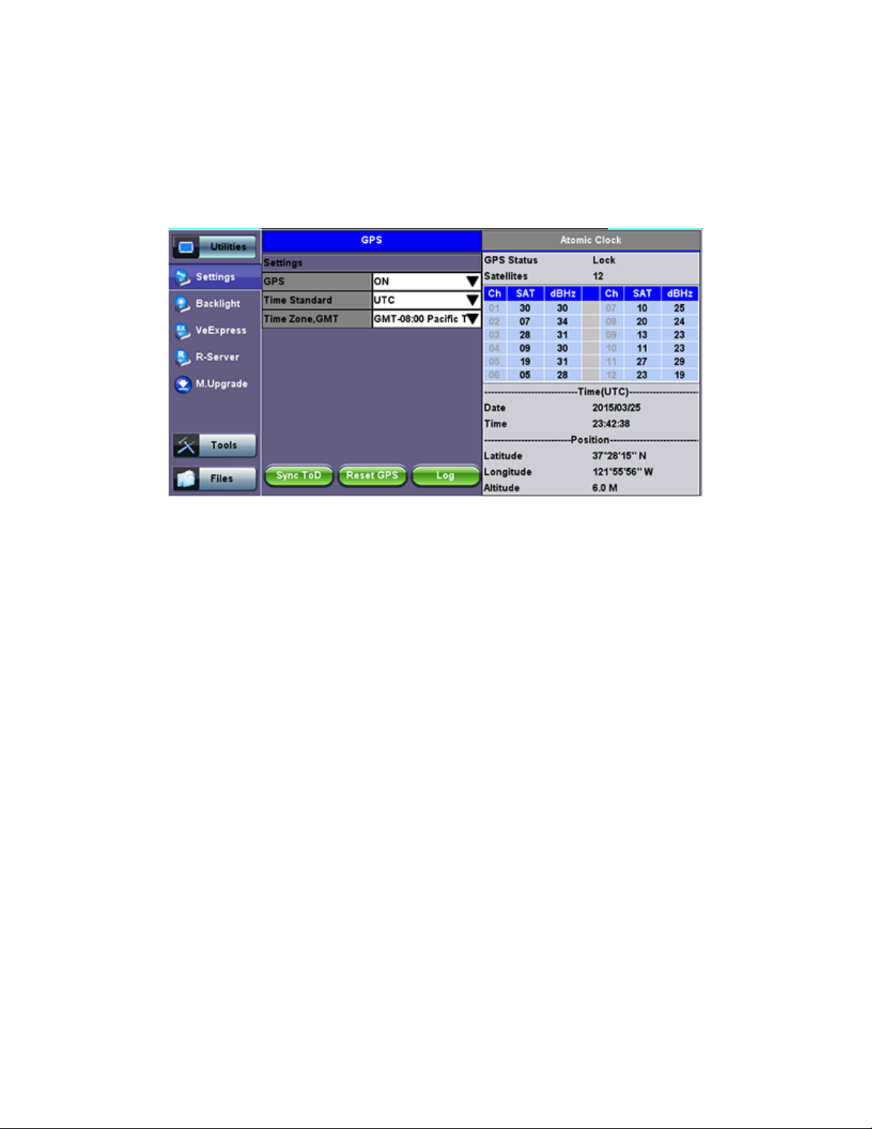
GPS Receiver (HW Option)
The optional high-sensitivity GPS module (built-in) provides accurate Phase alignment and Coordinated Universal Time (UTC)
synchronization to the test set, in the form of internal pulse-per-second (1PPS) clock synchronized to the standard second and time
stamps. This is used to assure that two or more geographically-distributed test sets have the exact same time and can calculate
delays. One example is the One-Way-Delay (Latency) tests used to identify asymmetry between each direction of a link.
The GPS Time of Day (ToD) can also be used to precisely set the local date and time in the test set, using the Sync ToD function,
which will apply the local time zone correction before applying it to the test set system real time clock. This time stamp is used for
reports and events, but not for time-sensitive testing.
GPS ToD is also used in One-Way-Delay (OWD) measurements and time is applied directly to each test set before the test starts,
so they all have accurate time.
The GPS receiver can be turned OFF if not used, to save battery power.
A satellite table, showing satellites in view, satellites being used and signal to noise ratio, is provided for information only, so the
correct antenna installation can be verified.
the future to
geo-tag some position-sensitive results. The GPS antenna must have a direct view to the sky. At least four satellites
Geographical coordinates
are also provided for information only and it could be used in
with SNR of 34 dBHz or better are recommended for accurate testing.
Atomic Clock (HW Option – Factory installed)
The optional built-in chip-scale Atomic Clock module provides a highly stable clock source to the test set, in the form of a highly
accurate and stable internal 10 MHz frequency reference. This reference can be used to drive PDH/DSn, SDH/SONET/OTN,
1588v2 PTP, or SyncE Master transmitters or be used as a reference for Frequency and Wander measurements. Its main function is
to serve as a precision reference to measure wander (clock stability), even in places where there are no reference clock signals
available that can be traced back to a Primary Reference Clock (PRC).
Page 47
GPS-Disciplined Clock
TX300s_Platform_Manual_RevB00
Page 47 of 104
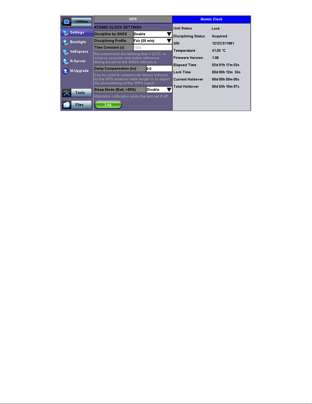
When GPS and Atomic Clock options are installed and enabled, the Atomic Clock uses the GPS signal to calibrate its frequency (10
MHz) and timing references (1PPS), to improve their accuracy and stability. The Atomic Clock 1PPS phase is disciplined to the UTC
to align it with the standard second. The raising edge of the 1PPS pulse indicates the beginning of a new second all over the world.
Disciplining can be disabled or enabled. When disabled, the atomic clock runs at its natural frequency (free-running), providing a
very stable frequency source. When disciplining is Enabled, the atomic clock will use the GPS accuracy to correct its frequency and
align its phase.
The Disciplining Profile sets a time window on the atomic clock's dynamic control loop, to filter any short term frequency and phase
variations coming from the GPS receiver, this is called Time Constant. The longer the time constant, the more accurate and stable
the atomic clock output can be. The Disciplining Profile field provides suggested options for the minimum disciplining times and sets
the equivalent Time Constant. The selection varies with applications and location, so some experimentation may be required by
users to select their own default value. For quick field Wander or Phase measurements a disciplining time of ≥ 60 minutes (TC ≥
1800 seconds) is recommended. Users can also enter a customized time constant in seconds.
Holdover
In case of GPS signal loss (e.g. indoor testing) the high stability of the Atomic Clock can maintain synchronization for a few hours
allowing users to perform Wander and Absolute Phase Error measurements in conditions that were not possible before. This is
called holdover mode.
Delay Compensation can be used to perform minor adjustments to the 1PPS phase, to align it to a specific reference or to
compensate for short cable delays.
When enabled, the low power Sleep Mode keeps the atomic clock powered up when the test set is turned off. This way it maintains
its last calibration by drawing little current from the batteries. In this state, the test set will only cut the power to the atomic clock if the
battery charge reaches a level less than 50% of charge, to conserve battery. The Elapsed Time counts the time since its first
initialization, including the time the test set has been off. If disabled, the atomic clock is shut down with the test set and will require
full initialization the next time it is powered up.
Atomic Clock Relative Phase Monitoring
VeEX test sets equipped with GPS receiver and Chip Scale Atomic Clock options include a relative phase monitoring tool that can
be used for the Relative Phase Measurements that provide a bit more visibility into the disciplining process.
In the absence of another traceable frequency source or timing reference, users have to rely on relative phase measurements. It is a
direct comparison between the GPS receiver’s “raw” 1PPS signal being fed to the high-precision oscillator (CSAC) and the filtered
(stabilized) 1PPS output from the oscillator, which ultimately would be the reference signal to be used by the test set for Wander,
Absolute Time Error (Phase) and One-Way Delay (link symmetry) measurements. Since the disciplined output combines the shortterm stability of the precision oscillator and the long-term accuracy of the GPS it provides the best of both worlds, so it can be used
to measure the internal GPS receiver output to verify they are in agreement.
Page 48
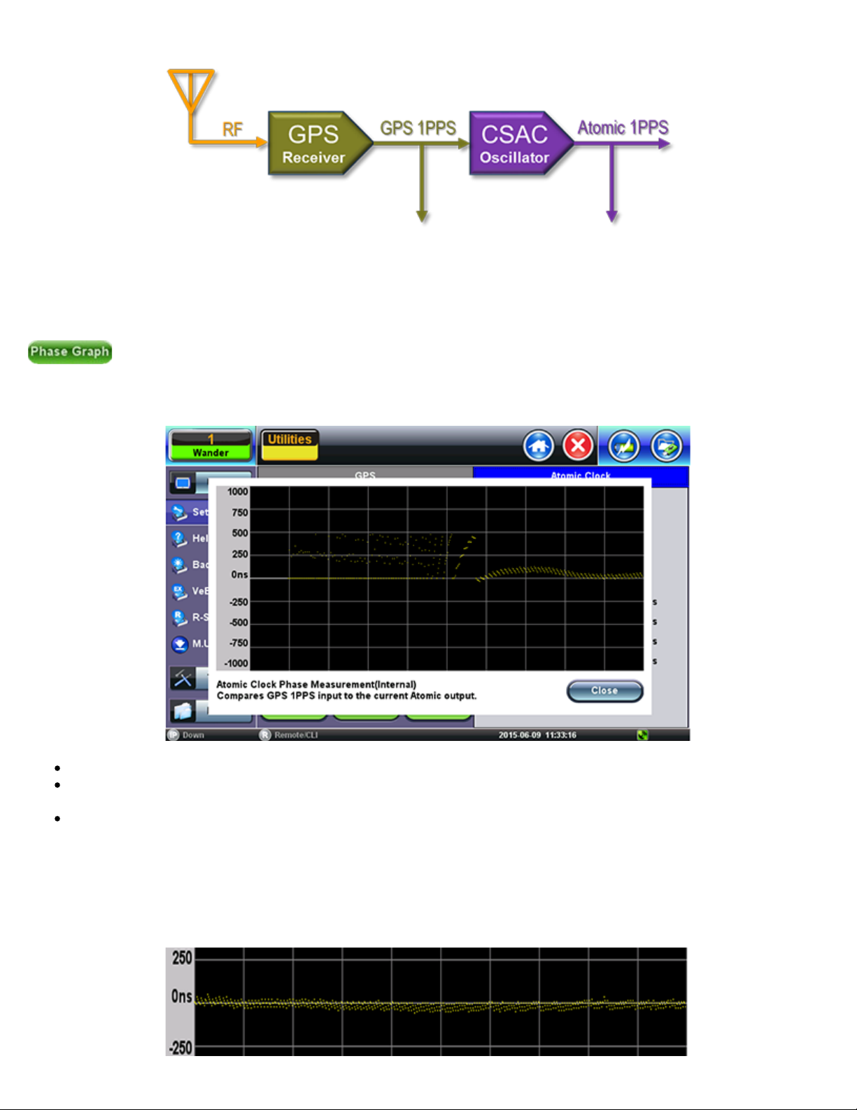
Relative phase compares disciplined Atomic 1PPS vs. GPS 1PPS
TX300s_Platform_Manual_RevB00
Page 48 of 104
Relative phase measurements are more useful when monitored at the beginning of the disciplining process, to track the phase
alignment between the oscillator’s output (Atomic 1PPS) and its input (GPS 1PPS). Since the oscillator filters the raw 1PPS noise
and fine tunes its frequency to align its own 1PPS to true time, the input vs output differential graph can become a very useful tool to
monitor and verify that the convergence process is going as expected.
The Atomic Phase Graph can be found in the Atomic Clock settings and status screen at >Utilities >Settings >More
>High Precision Clock Source >Atomic Clock
Example of GPS-disciplined Atomic relative phase convergence graph
Yellow dots indicate valid relative phase measurements (output - input).
Scattered yellow dots could indicate bad GPS signal, which in turn provides bad timing accuracy, or that the oscillator trying
to compensate for large phase differences.
White dots (line) at zero indicates loss of GPS 1PPS. It basically indicates holdover periods.
What you want to see in
this graph is a tight bundle of differential phase measurements forming a line converging to zero and
staying at zero. Since the Atomic Clock output is very stable, it will slowly try to infer the true (accurate) time alignment out of the
GPS 1PPS output and maintain it. The less disperse the individual measurements (dots) are, the better the GPS timing signal is. So,
you want to see a straight line formed by not-so dispersed group of dots.
Example of proper (converged and stable) phase alignment
Page 49
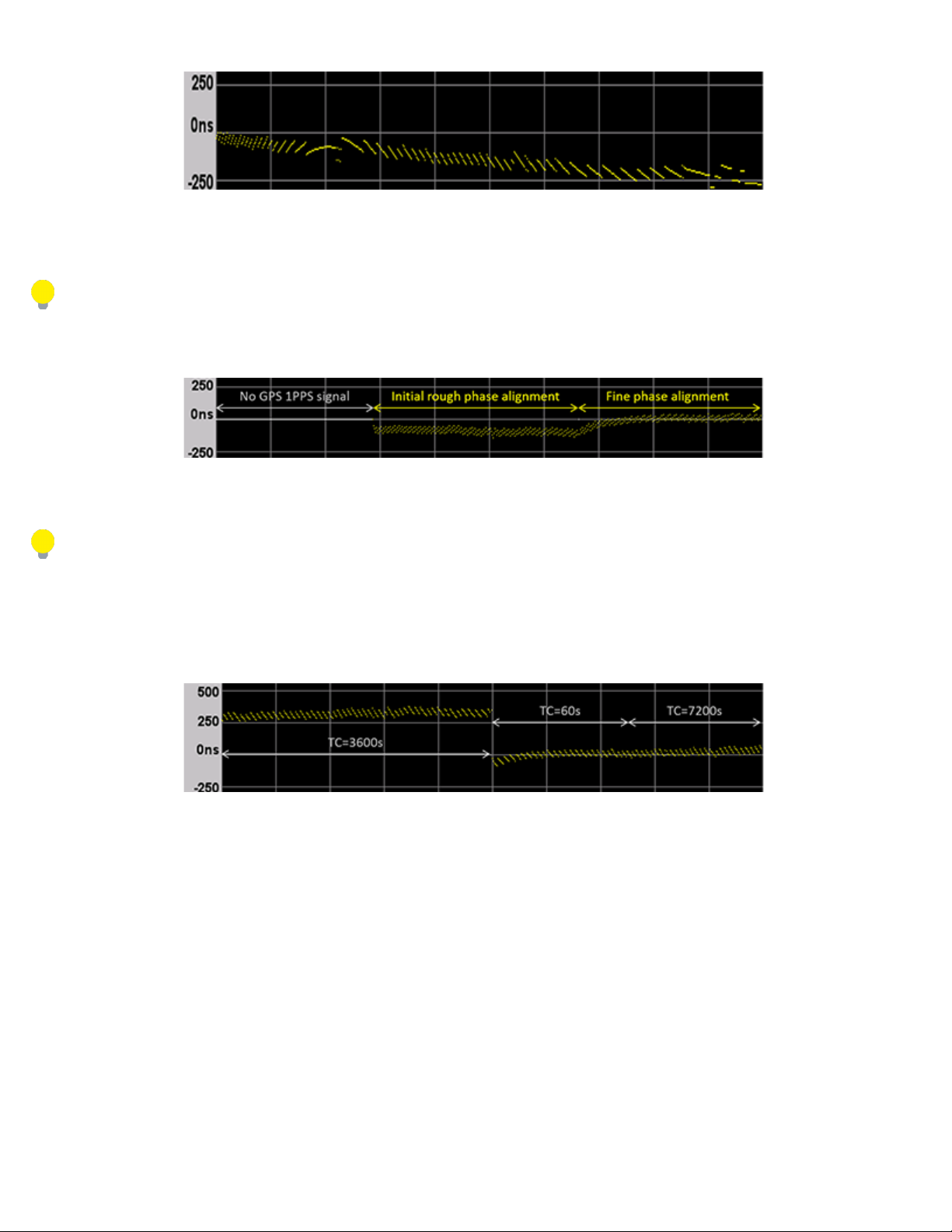
Not so good phase alignment
TX300s_Platform_Manual_RevB00
Page 49 of 104
The chip scale atomic clock oscillator uses its 10 MHz frequency source for the disciplining process. Its 1PPS phase is initially
aligned to the 10 MHz phase, so it should be within ±100 ns (one 10 MHz cycle). Then the CSAC would start steering its frequency
to finely align its 1PPS output within a few nanoseconds to the “average” 1PPS input coming from the GPS receiver.
In the context of this document the term “GPS Receiver” is not considered a synonym of “GPS Clock” or “GPS-disciplined Clock”.
A GPS Clock is considered a combination of a GPS receiver and a highly stable precision oscillator.
Example of initial phase alignment
Although the relative phase alignment may converge rather fast in many occasions, users must still observe the minimum
recommended disciplining time.
If the disciplining time constant (TC) is changed in the middle of the process, from one long value to another, the phase may take
long time to converge to zero or could display a somewhat erratic behavior for a while. In this scenario, if users need to change the
TC, it may be worth temporarily changing it to a short TC (e.g. 60s) for faster steering and then change it to the desired value. (Note
that although the Sync 1PPS button could also be used to force alignment of the Atomic 1PPS output, it does not adjust the required
disciplining or steering parameters.)
Using short TC to force quicker phase convergence to zero
Phase Alignment and Holdover
Knowing whether the oscillator is still steering (changing) its frequency to correct the 1PPS output’s phase has a big impact in
deciding when to force the test set into holdover for indoors testing. The Phase Graph can help in identifying when the disciplining
process has stabilized.
A disciplined oscillator will continuously adjust its frequency to keep the 1PPS aligned to the standard second, but those offset
adjustments are usually small fractions of ppb when proper disciplining has been achieved.
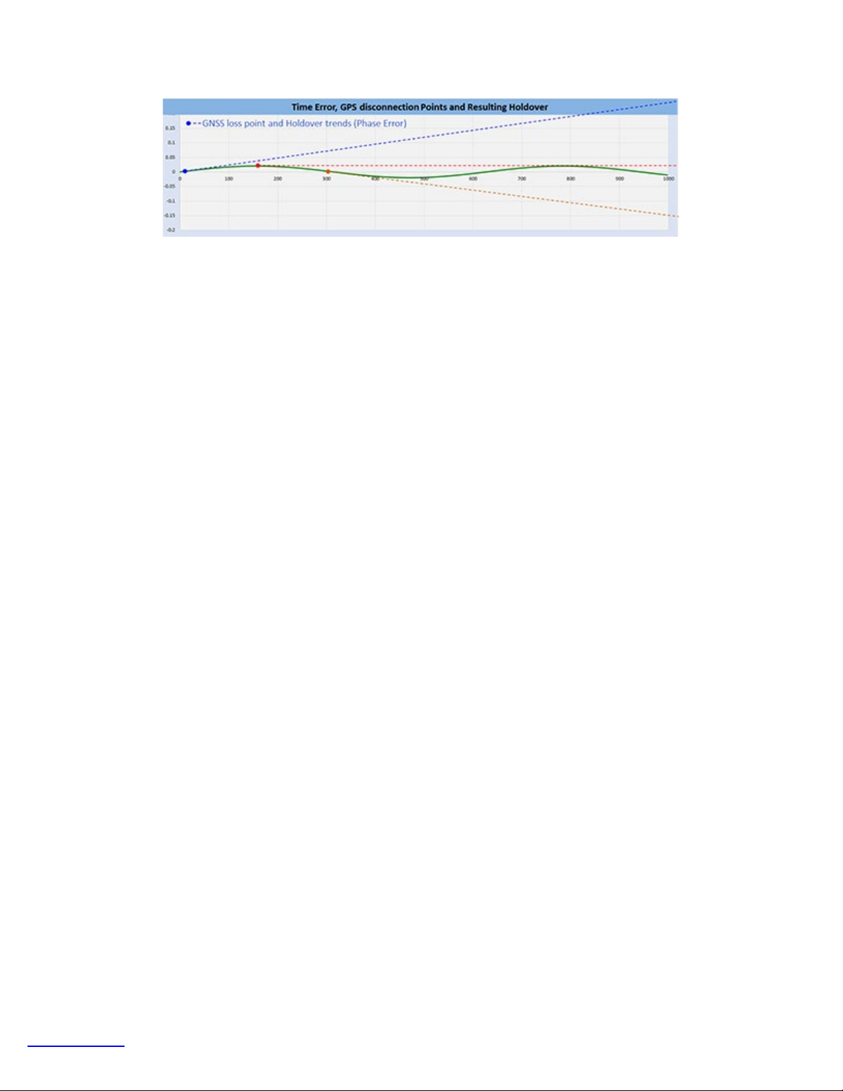
Upon the loss of the GPS 1PPS reference, the oscillator enters holdover mode. This means that the precision oscillator will hold its
last frequency and the phase error will continue its trend. That means, you want the instantaneous frequency to be as accurate as
possible at the moment when the GPS receiver is turned off. Keep in mind that any ±X.XXX ppb frequency offset would result in a
cumulative time error of ±X.XXX ns per second and that would impact the resulting usable holdover time, by reaching the defined
error tolerance faster or slower.
Page 50
TX300s_Platform_Manual_RevB00
Page 50 of 104
Illustrative examples of what would happen if GPS 1PPS is lost during different steering stages
Limitations: This method of determining proper 1PPS phase disciplining convergence would only work at the beginning of the
disciplining process, which is what would be needed in the field.
Long-term, especially when long time constants are used, the oscillator will become hard to steer as it would be trying to hold what it
“believes” is true time alignment, based on a long learning process. In this case, if the GPS receiver starts to wander and becomes
somewhat inaccurate, the graph would show such discrepancy, but the oscillator’s 1PPS output would still be stable and accurate.
GPS instant accuracy could change within ±150ns during the course of a day depending on atmospheric conditions and satellites
visibility. The job of the atomic clock is to filter those slow variations, so in the long term it is normal to see the GPS and CSAC
phases temporarily disagree (relative phase ≠ zero).
Warm Up Times
All precision reference sources require a “warm up” time to achieve high accuracy and stability. The warm up term is being used
loosely because it is not just about attaining the right temperature. It also includes disciplining of a local oscillator, negotiating and
stabilizing a clock through protocol messages, etc. Each of the tasks involved takes time to stabilize before it can be used for testing.
Operational Temperature
It is still a major player in the warm-up waiting time and it all depends on the ambient temperature and the initial temperature of the
test set. For example, a test set left in the trunk of a car in a winter night will take longer to reach operational temperature.
Atomic Clock Warm Up
If fitted with a chip-scale atomic clock, they are housed in a miniature oven to maintain its internal temperature constant in spite
variations in ambient temperatures and it can take up to five minutes to warm up and should not be used until its status shows
“Locked”. The atomic clock temperature and status can be monitored at \Utilities \Settings \More \High Precision Clock Source
\Atomic Clock. The chip-scale atomic clock is oven-controlled and temperature-compensated to minimize the effects of ambient
temperature variations.
Beside temperature, users must be aware of other factors that require time to settle, before accurate measurements can be made.
GPS Lock
The time to get an stable clock output varies depending on the conditions, antenna type and installation, sky visibility and whether or
not the test set has changed position. Using the test set for the first time on a new site (different geographical position) would
increase the time to its first satellite lock. Users can follow the different stages (Searching, Sync 1PPS, and Lock) by checking the
GPS status GUI at >Utilities >Settings >More >High Precision Clock Source >GPS
Disciplining Time
Disciplining the atomic clock means using the accurate GPS timing signal to correct or align the atomic clock output signals. GPS is
known for its high accuracy as it is traceable to the universal time standard (UTC). Atomic Clocks are known for their great stability.
So, the combination of GPS + Atomic Clock = Highly Accurate and Stable clock source. Achieving such levels of precision takes
time. The total time to stable output depends on the precision required. The disciplining time can be programmed in the Atomic
Clock settings and users must add it to the total “warm-up” time, before starting measurements.
Precision Timing Protocol
PTP, like IEEE 1588v2, requires some time for the two ends (master and slave) to agree on the current time. This protocol “warmup” time is dependent on the link conditions (traffic, latency, delay variations, PTP settings, etc.). Tests shall not be started until the
protocol has stabilized and the recovered clock has achieved its maximum accuracy and stability. This is sometimes referred as
“Convergence” or “Sync PDV” convergence. Users can use the long tail of the 1588v2 Sync PDV graph as an indication the PTP
has reached synchronous state.
Go back to TOC
Page 51
5.2 Help
TX300s_Platform_Manual_RevB00
Page 51 of 104
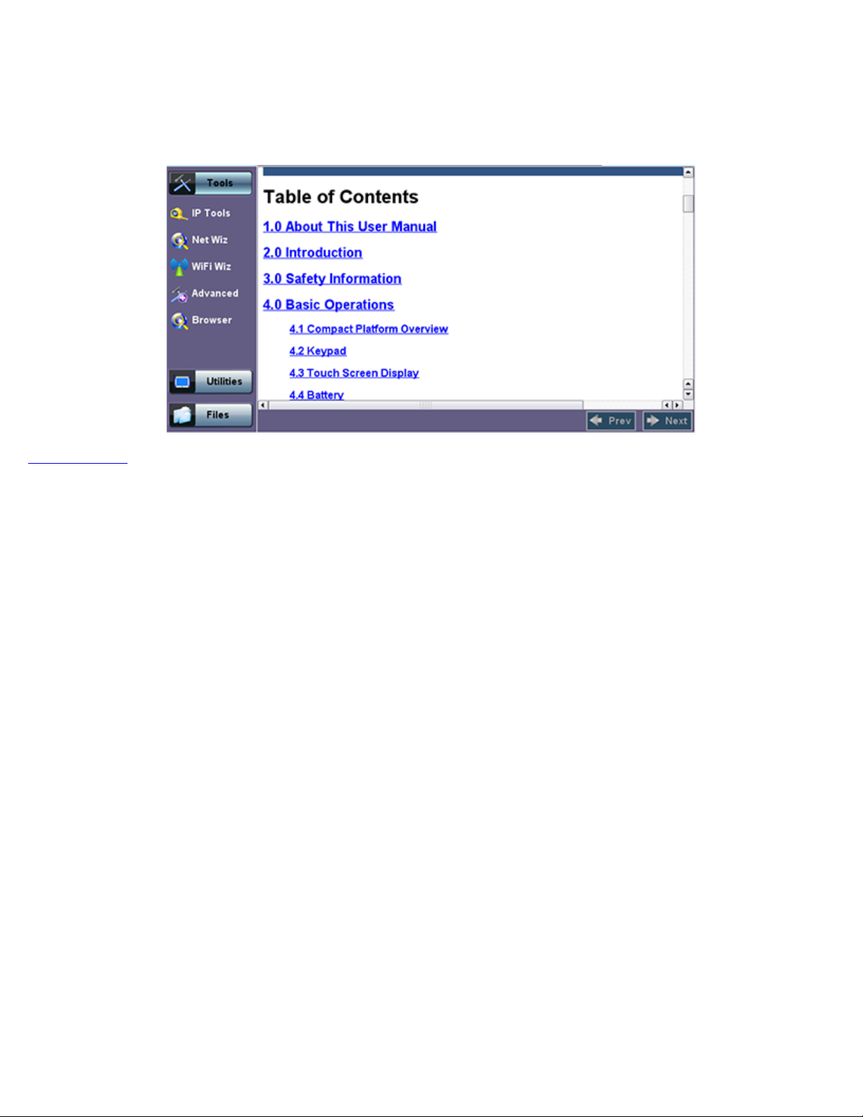
Help provides an online help related to the operation of the test set and the measurements performed. The user can access the
table of contents, and hyperlinks. Use the scroll bars to navigate help content.
Help Menu
Go back to TOC
Page 52
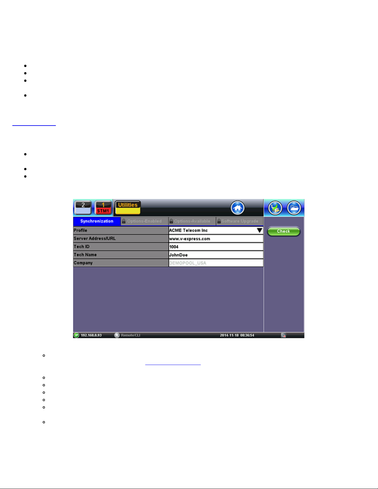
5.3 VeExpress
TX300s_Platform_Manual_RevB00
Page 52 of 104
VeExpress is a cloud-based asset management system. VeEX VeExpress cloud services is included with every test set. It allows the
following services / functions:
Delivers Software/Firmware Updates and Upgrades directly to the test set.
Makes any new Purchased or Rented licenses (new functions) assigned to the test set immediately available for testing.
Allow Managers to Share (float) purchased or rented test options among deployed test sets (fleet). Licenses can be
temporarily assigned to the test set that needs it, for specific jobs, and later recalled to pass it on to the next test set.
Allows users to rent optional test features (licenses) for the required amount of days. Adds the flexibility required for special
jobs or those new technologies or services that are not yet commonly deployed. Rented options are automatically released
when lease time elapses (no need to connect to the server).
Go back to TOC
5.3.1 Built-in VeExpress Client
Lets users connect to VeExpress Cloud directly from the test set, from the field, using any available internet connection (e.g.
LAN, Wi-Fi, Modem, CPE, Smartphone hot-spot, Cellular Data Card, etc.)
View test features currently assigned to the test set and licenses available in the pool
Activates new licenses and let users perform software (firmware) updates
Connecting VeExpress:
1. Connect the TX300s to the Internet.
Use LAN, WLAN or Cellular DatSa Card
2. Go to >Utilities >VeExpress: The URL is:
3. Tap on the Check button.
Any tests must be stopped and released
Confirm the Release of any active Test Application
It gets the latest information related to the test set, directly from VeExpress Cloud
Enables any new licenses assigned
Releases any recalled shared licenses
4. Wait for the Confirmation message: “Registered and Authorized”.
All Licenses have been updated and any new features should be ready to use
www.v-express.com.
Page 53
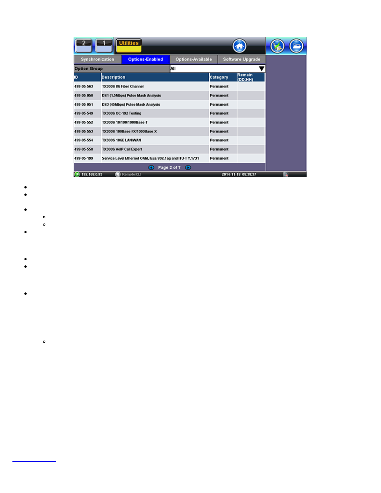
Options Enabled (in the Test Set)
TX300s_Platform_Manual_RevB00
Page 53 of 104
Up-to-date list of licenses assigned
Permanent = Purchased, owned (users can still share permanent licenses by releasing the option from one test set and
assign it to another)
Leased = Rented, temporary
Displays remaining time (Days and Hours)
Countdown starts upon first assignment
Both permanent & leased can be shared
Options Available (in the Cloud)
Lists all options, permanent or leased, currently available in the company’s or group’s VeExpress account
Users can check availability before requesting assignment of new function(s) to their VeExpress Managers
Software Upgrade
Checks if newer version is available
Go back to TOC
5.3.2 Software Upgrade Procedure – Full Version
1. Open the Software Upgrade tab.
Larger Full Upgrade package is shown if the test set has not been updated for a while, when major new features are
introduced or an OS update is required
2. Attach the DC charger to the test set.
3. Insert a FAT32 USB Memory Stick into the left-side USB port (>300MB free).
4. Confirm IP connection (IP address).
5. Check the new software version box .
6. Tap on the Download button.
1. Wait until the download process finishes. Install package is in the memory stick.
2. Power the test set OFF.
3. Leave the USB memory stick attached.
7. Initiate Software Upgrade process.
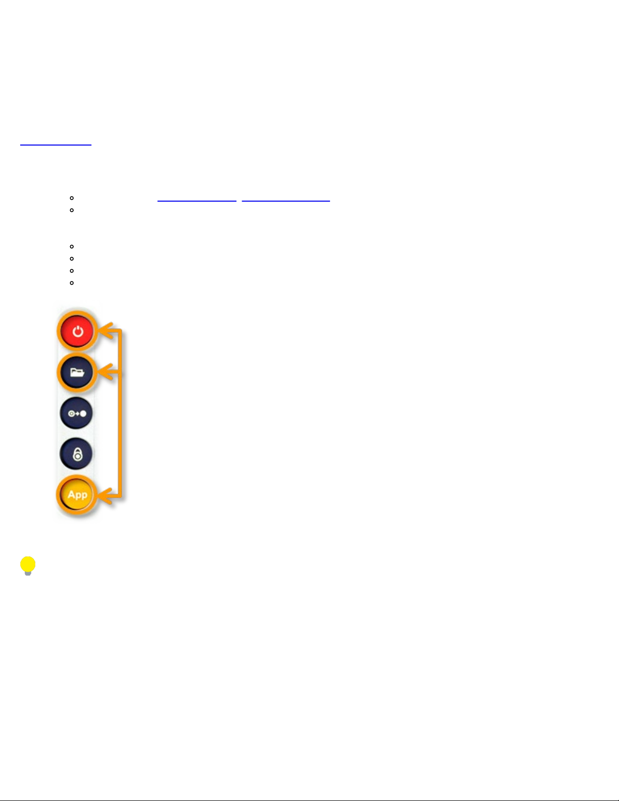
1. Simultaneously press the App, and Power buttons, until it beeps.
2. Let the upgrade process finish (it could take a few minutes).
3. The test set reboots itself at the end.
8. The test set is now up-to-date.
Go back to TOC
Page 54

5.3.3 Software Upgrade Procedure – Delta Version
TX300s_Platform_Manual_RevB00
Page 54 of 104
1. Open the Software Upgrade tab.
Smaller Delta Update package is often made available between consecutive versions (e.g. from 1.2.5 to 1.2.6) for
easier and faster field firmware update
2. Attach the DC charger to the test set.
3. Confirm IP connection (IP address).
4. Check the new software version box.
5. Tap on the Download button.
1. Wait until the download process finishes.
2. The install package is in internal memory.
3. Turn the test set OFF.
6. Power the test set ON.
7. The test set software is now up-to-date.
Go back to TOC
Page 55
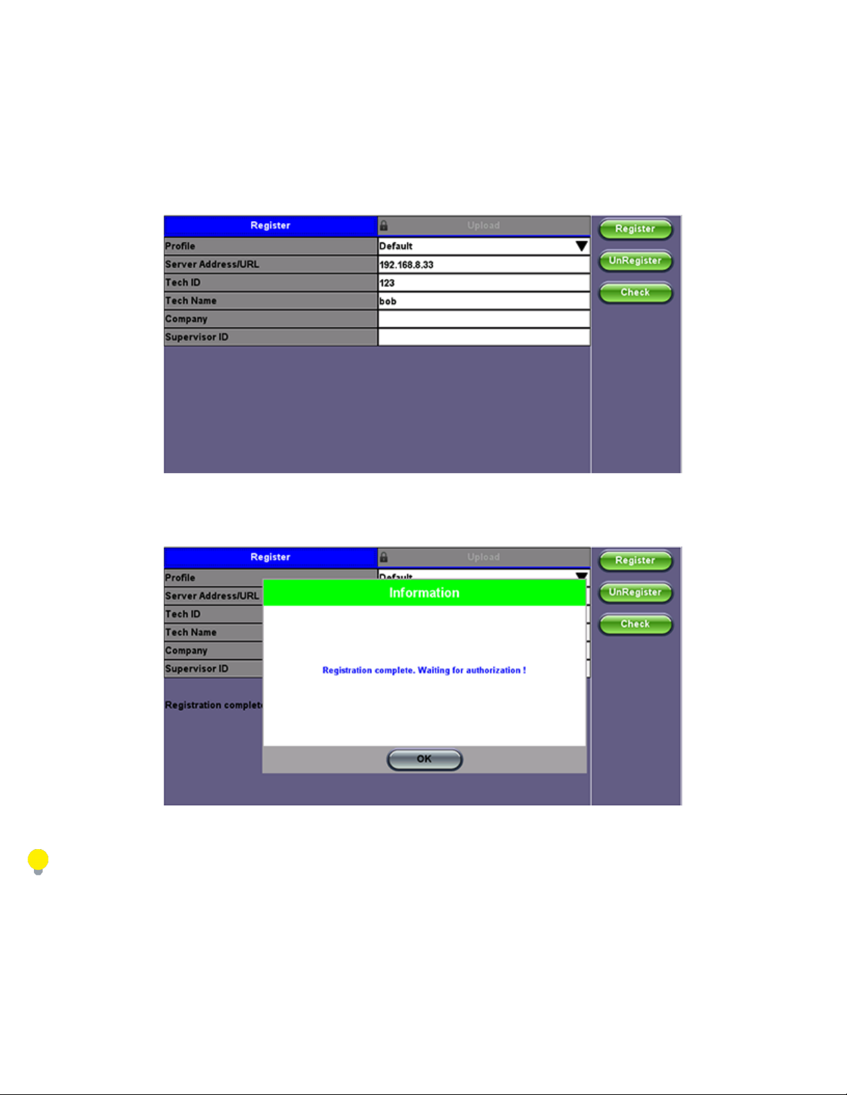
5.4 R300 Server (Advanced Management)
TX300s_Platform_Manual_RevB00
Page 55 of 104
The R-Server is a centralized server repository for test results. Technicians in the field can register their test set on the R-Server and
upload test results directly to the server.
To enter the R-Server result upload function, there must be an IP connection established, otherwise a reminder message will pop
up.
Register
1. Enter the IP address of the server.
A test set must register to an R-Server before it can upload results to the server.
2. Press the Register button to register your test set on the R-Server.
If your test set has already been registered, you don't need to preform this step.
The Registration has to be approved by the R-Server manager before access is allowed.
Page 56
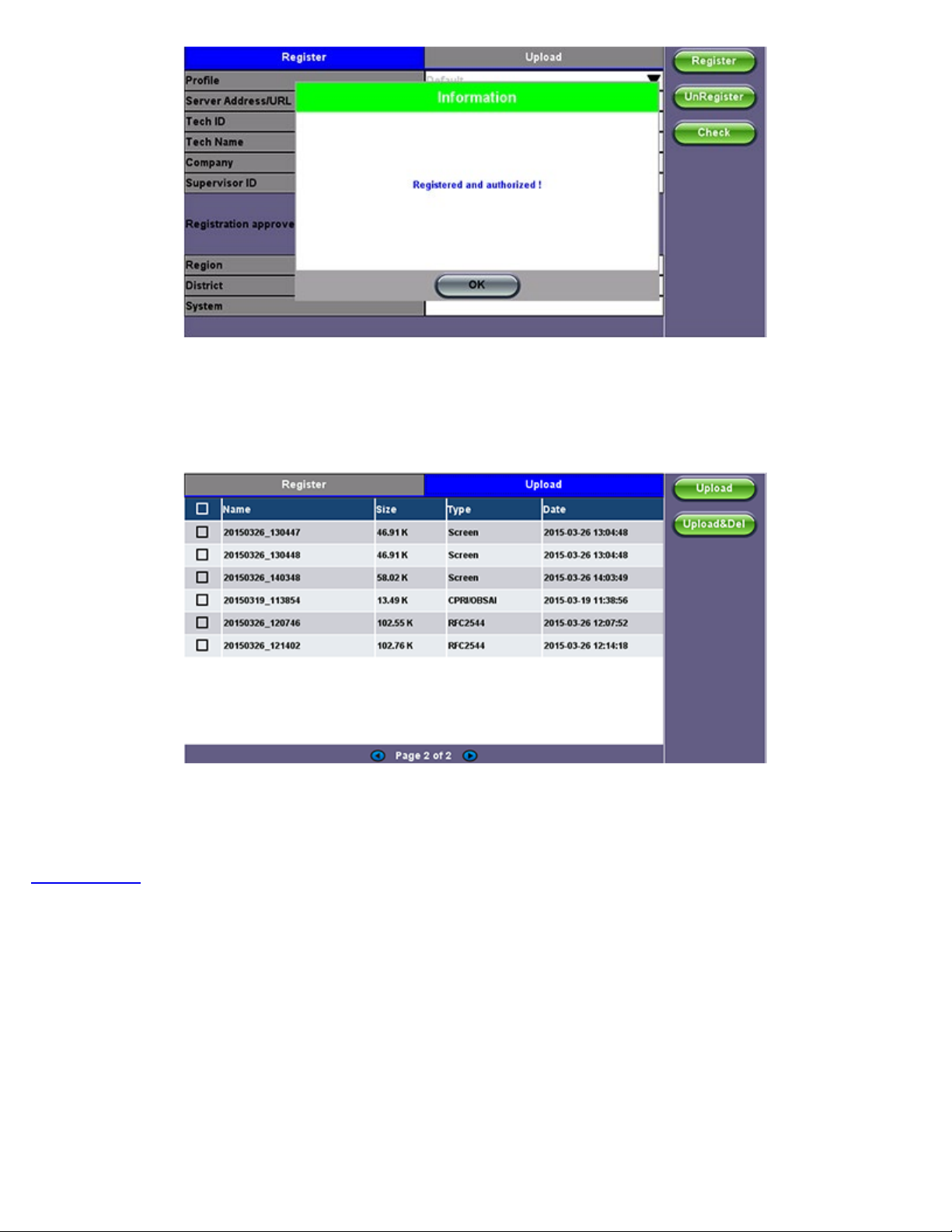
3. When the test set registration is complete and approved by the R-Server manager, you can select Check function button to verify
TX300s_Platform_Manual_RevB00
Page 56 of 104
that your test set is authorized.
Once your test set is authorized, you can proceed to Upload.
Upload
To upload result files to the R-Server, tap the Upload tab and select the desired files. Tap on Upload or Upload&Del.
Upload: Transfers the selected result file(s) and keep the file(s) in the test set
Upload&Del: Deletes the file(s) from the test set after uploading
Go back to TOC
Page 57
5.5 Software Upgrade
TX300s_Platform_Manual_RevB00
Page 57 of 104
TX300s Platform includes the bootloader, OS and system-wide (common) features. Its software update package can be identified as
tx300s-veex.tar.gz.
The TX300s Platform uses the traditional V300 upgrade procedure to update the System. The software upgrade packages can be
downloaded from www.veexinc.com, or using the test set’s built-in VeExpress client.
Go back to TOC
5.5.1 Platform Software Upgrade Procedure
1. Obtain the tx300s-veex.tar.gz system upgrade package.
Download it from www.veexinc.com, www.v-express.com, a link provided or by using the built-in VeExpress client.
Unzip the file and copy to the root of a FAT32 USB memory stick if necessary.
2. Insert the memory stick to the USB port located on the left-side of the unit.
3. Initiate Software Upgrade process.
Simultaneously press the App, and Power buttons, until it beeps.
Let the upgrade process finish.
It could take a few minutes.
The test set reboots itself at the end.
4. The test set is now up-to-date.
After the System Upgrade, the following pop-up message may appear if a Module Upgrade is required. Follow the module
update procedure.
Page 58
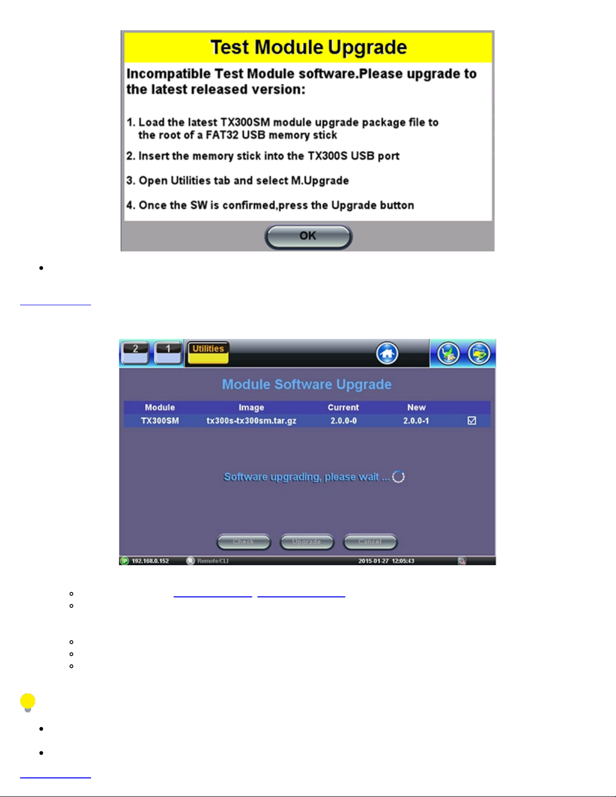
The built-in VeExpress client downloads the uncompressed tx300s-veex.tar.gz upgrade package directly to the root of the
TX300s_Platform_Manual_RevB00
Page 58 of 104
memory stick attached to the test set, so the System software upgrade process can be started right away.
Go back to TOC
5.5.2 Module Software Upgrade Procedure
1. Obtain the required tx300s-300sm.tar.gz, tx300s-320sm.tar.gz and/or tx300s-OTDR.tar.gz/em>, upgrade files.
Download them from www.veexinc.com, www.v-express.com, a link provided or by using the built-in VeExpress client.
Unzip the files and copy to the root of a FAT32 USB memory stick if necessary.
2. Insert the memory stick to the USB port located on the left-side of the unit.
3. Initiate Software Upgrade process.
Open the Utilities section Go to >Utilities >M.Upgrade.
Select new version and press Upgrade.
The test set turns itself OFF at the end.
4. The test applications are up-to-date.
The built-in VeExpress client downloads the uncompressed tx300s-xxxx.tar.gz upgrade packages directly to the root of the
memory stick attached to the test set, so the M.Upgrade process can be started right away
The process may need to be repeated if two different blade types are loaded.
Go back to TOC
Page 59
6.0 File Management
TX300s_Platform_Manual_RevB00
Page 59 of 104
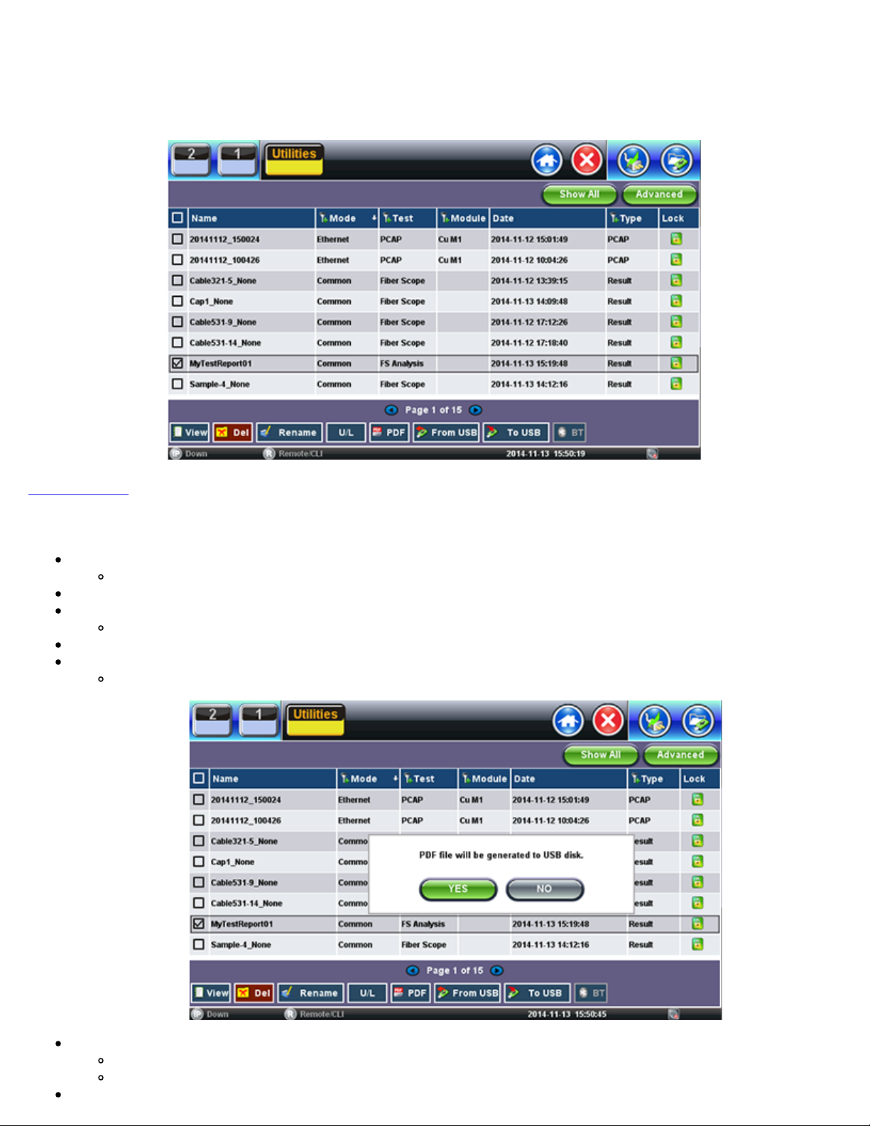
V300 Style File Manager
Go back to TOC
6.1 File Manager: Working with Saved Results, Profiles, Images
From Utilities go to >Files >Saved.
Displays all results stored in the test set
Use the check box to select the desired files.
Tap on any column header to sort by that specific parameter.
Tap again to change the sorting order.
The U/L button lock and unlock files to prevent accidental deletion
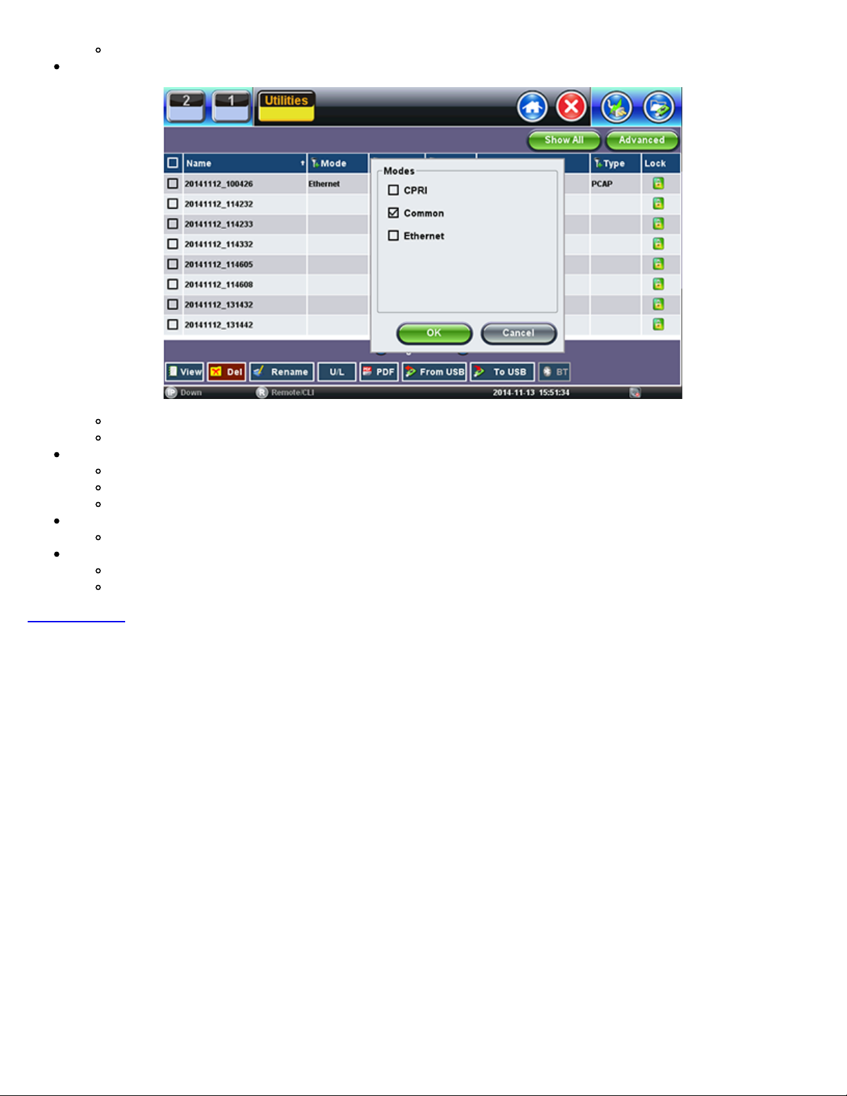
PDF button converts all selected files to PDF format
Requires FAT32 USB Memory stick
Backup and Restore (USB Memory stick):
To USB copies all selected files to stick
From USB restores all files from the stick
BT (Bluetooth®) File Transfer
Page 60
Requires compatible USB dongle
File Filters
TX300s_Platform_Manual_RevB00
Page 60 of 104
Makes it easier to isolate desired types of results from all other test results stored in the test set
Reduces the number of pages displayed
Activate Filters
Use the stylus to tap on the Y+ icon.
Check mark the desired attributes.
Filters parameters can be combined
Reset Filters
Press the Show All button.
Sorting
Tap on a header to sort by that field’s type, in ascending or descending order.
Makes finding desired test Results or Reports even easier
Go back to TOC
Page 61
6.2 USB Memory Browser
TX300s_Platform_Manual_RevB00
Page 61 of 104
USB Tool
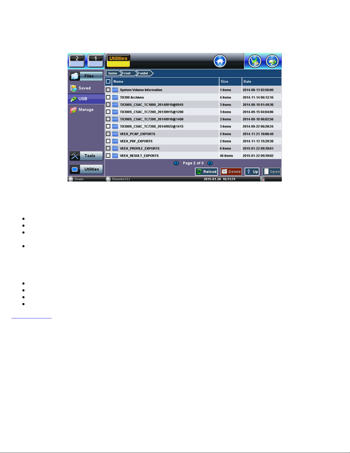
The USB tool can be found in the Utilities section, under >Files >USB.
It provides users with basic memory stick management tools, to browse and interact with its contents without the need of a PC:
Reload: Refreshes the USB stick info
Delete: Erases the selected files or folders
Up: Exits the current folder and moves up to a higher folder in the file tree hierarchy. The current folder structure is shown in
the top bar
Open: Opens certain file types
The USB tool supports one USB memory stick. It shows the first memory stick that is recognized, from any of the two ports.
The following file types are supported:
HTML: Launches the browser to display its content
TXT: Launches a basic text viewer to display its content
PCAP: Launches the built-in Wireshark® protocol analyzer
MTIE: Launches the optional built-in Wander Analysis tool
Go back to TOC
Page 62
6.3 Manage SD Card
TX300s_Platform_Manual_RevB00
Page 62 of 104
Internal SD Card Format
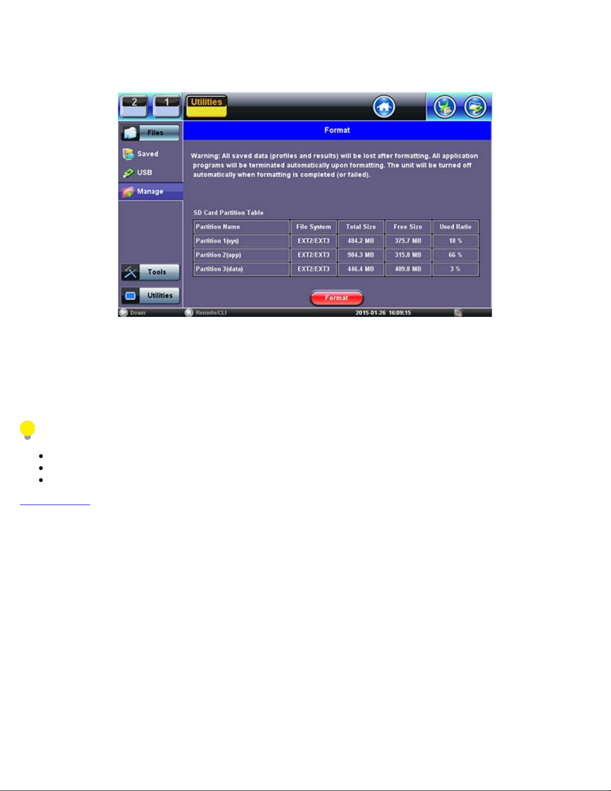
The Files >Manage tool under utilities provides SD card’s partition capacity information.
All the user information, such as test results, profiles, screenshots, protocol capture, etc., is stored in the Data partition (3). Use the
>Files >Saved >To USB backup utility or Delete function if the Data partition is nearly full.
The Format function is exclusively a maintenance tool. Use ONLY when instructed by a VeEX Customer Care representative. It
erases all the information stored in the test set.
The internal 2GB SD Card contains the System OS, all the Test Applications (Apps) and user’s data
Only the Data partition is accessible to users, through the test set’s functions
Do not remove or reformat the SD Card outside of the test set
Go back to TOC
Page 63
7.0 Tools
TX300s_Platform_Manual_RevB00
Page 63 of 104
7.1 IP Tools
The 10/100BaseT management port is located on the right hand side of the unit. This port can be used to connect to the unit for
management purposes (results retrieval, software upgrade, remote connectivity, ect.).
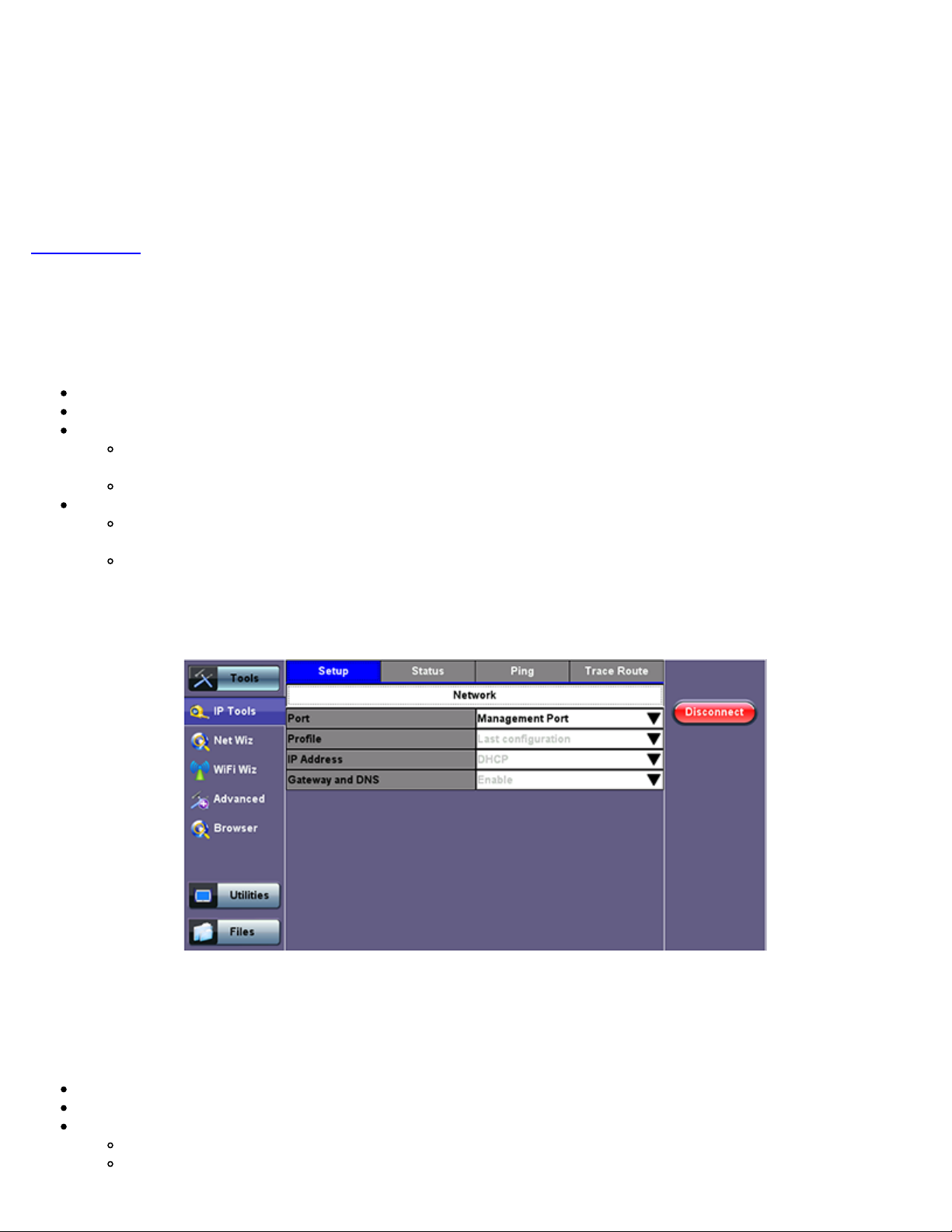
You can access the management port configuration on the Tools > IP Tools menu.
Go back to TOC
7.1.1 Setup
By detault the IP configuration is set to DHCP and the unit will automatically attempt to connect.
For IP configuration, the following fields are required. Additional fields vary depending on Static or DHCP connection.
Port: Select Management Port from the drop-down menu
Profile: Default, Delete, Save, Save as..., Default, or Last configuration
IP Address: Select from Static or DHCP
Static: If Static is selected, the user will manually enter the IP address parameters (local IP, Gateway IP and DNS
server IP)
DHCP: If DHCP is selected, the unit will obtain IP address parameters from the DHCP server
Gateway and DNS: Enable or Disable
Enabled: If enabled, enter the IPv4 address of the Gateway and DNS server in Static mode, or use the IP address
provided by the DHCP server in DHCP mode
Disabled: If disabled, no Gateway or DNS server will be used for the tests
Enter all parameters then press Connect to start the test.
DHCP Setup
For Static type connections, these additional fields are required:
Static: The user is required to enter a Local IP, Gateway address (if Gateway and DNS are set to Enable), and Subnet. All Static
fields can be filled by tapping on the section to access an alphanumeric keypad.
Local IP: IPv4 address of the test set
Subnet: Enter the subnet mask
Gateway and DNS: Enable or Disable. If set to enable, Gateway and DNS fields become available
Gateway: Off or On. IPv4 address of the network gateway
DNS: Off, Primary, or Primary & Secondary. If set to Primary or Primary & Secondary, a DNS IP is required in order to
use the URL as a
destination
Page 64
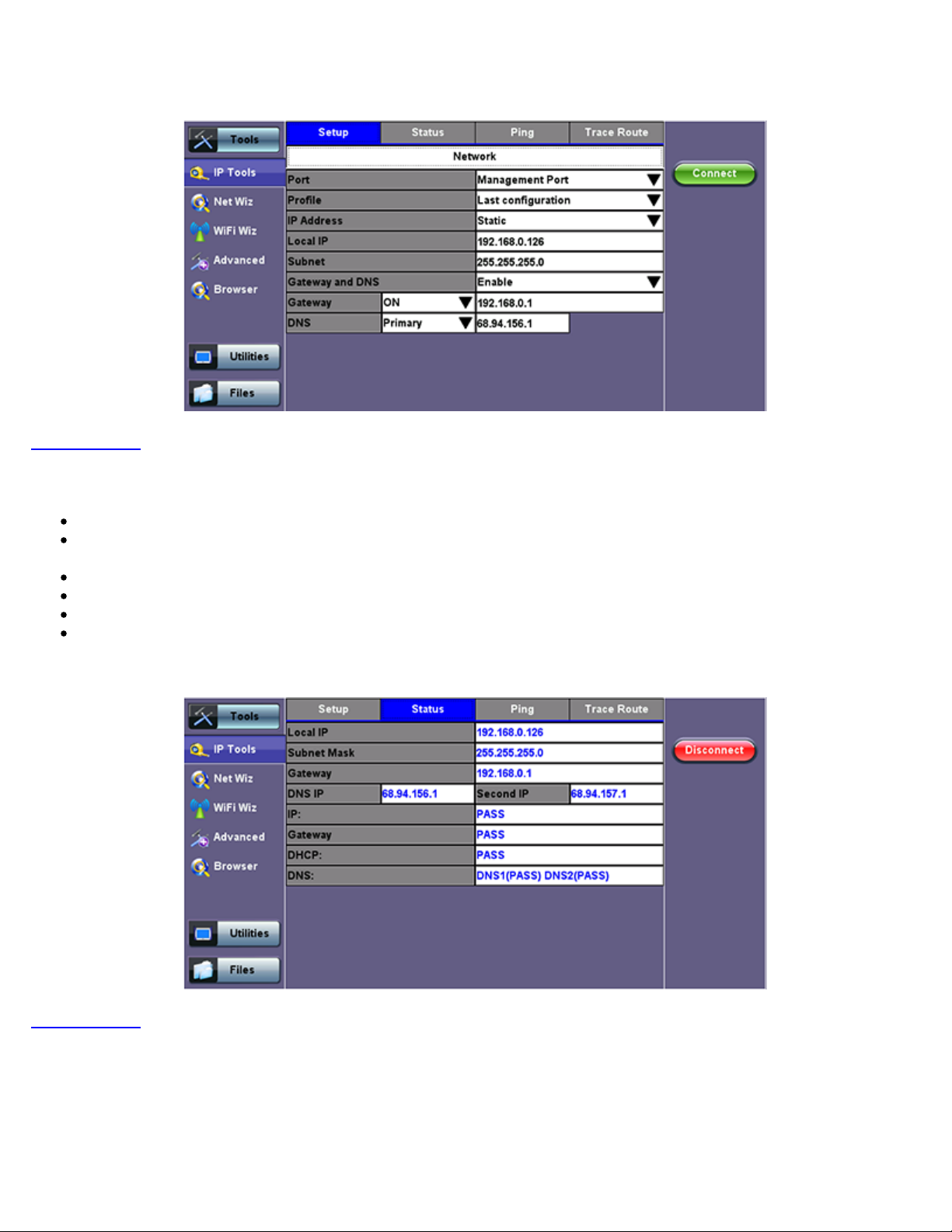
Enter all parameters then press Connect to start the test.
TX300s_Platform_Manual_RevB00
Page 64 of 104
Go back to TOC
7.1.2 IP Connection Status
Ensure the Status is PASS before continuing with any IP tests.
If the connection fails, go back to the setup screen to verify that the parameters are entered correctly. Verify that the Ethernet
cable is properly connected on the management port.
DHCP: PASS indicates that an IP address has successfully been assigned.
IP: PASS indicates that the IP address assigned has been verified to be unique in the network.
Gateway: PASS indicates that the gateway IP address is valid.
DNS: PASS indicates that the DNS IP address is valid.
Static Setup
Go back to TOC
IP Connection Status
Page 65
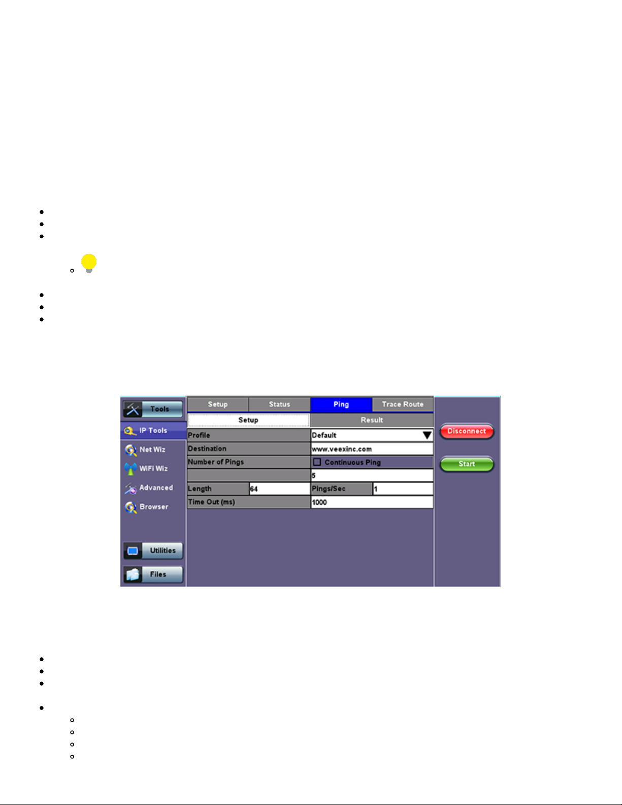
TX300s_Platform_Manual_RevB00
Page 65 of 104
7.1.3 Ping
The Ping Result provides the number of Sent, Received, Unreach, Missing, and the Round Trip delay.
Ping Testing
Ping is a popular computer network tool used to test whether a particular host is reachable across an IP network. A ping is
performed by sending an echo request or ICMP (Internet Control Message Protocol) to the host, and listens to echo response
replies.
Ping Setup
Profile: Delete, Save, Save as..., or Default.
Destination: Enter the destination IP address or URL to ping.
Number of Pings: Press the field and use the alphanumeric keypad to enter the number of ping attempts that will be
performed to reach the network device.
If Continuous Ping is selected, the user is not required to enter the number of pings. The test set will continuously
ping the target host until the user presses Stop.
Length: Use the alphanumeric keypad to enter the length of the ICMP echo request packet transmitted.
Ping/Sec: Use the alphanumeric keypad to enter the Ping repetition rate (Ping/second) up to 10 pings per second.
Time Out: Time-to-Live (TTL) in milliseconds. Use the alphanumeric keypad to enter the maximum time allowed (in ms, up to
99999ms) between an ICMP ping and echo response.
Once the parameters are configured, press Start to begin the test.
Ping Setup
Ping Results
Pressing Ping will take you to the Result tab and start the Ping test.
Destination: Indicates the destination IP address
Ping status: In Progress, PASS, or FAIL
Sent, Received, Unreach, Missing: Number of pings sent, received, unreached or missing. A Ping is counted missing if no
response is received before timeout. A Ping is counted unreached if an echo response is received with host unreachable set.
PING also estimates the round-trip time in milliseconds
Current: The current time for a Ping request to be answered
Average: The average time recorded for a Ping request to be answered
Max: The maximum time recorded for a Ping request to be answered
Min: The minimum time recorded for a Ping request to be answered
Page 66
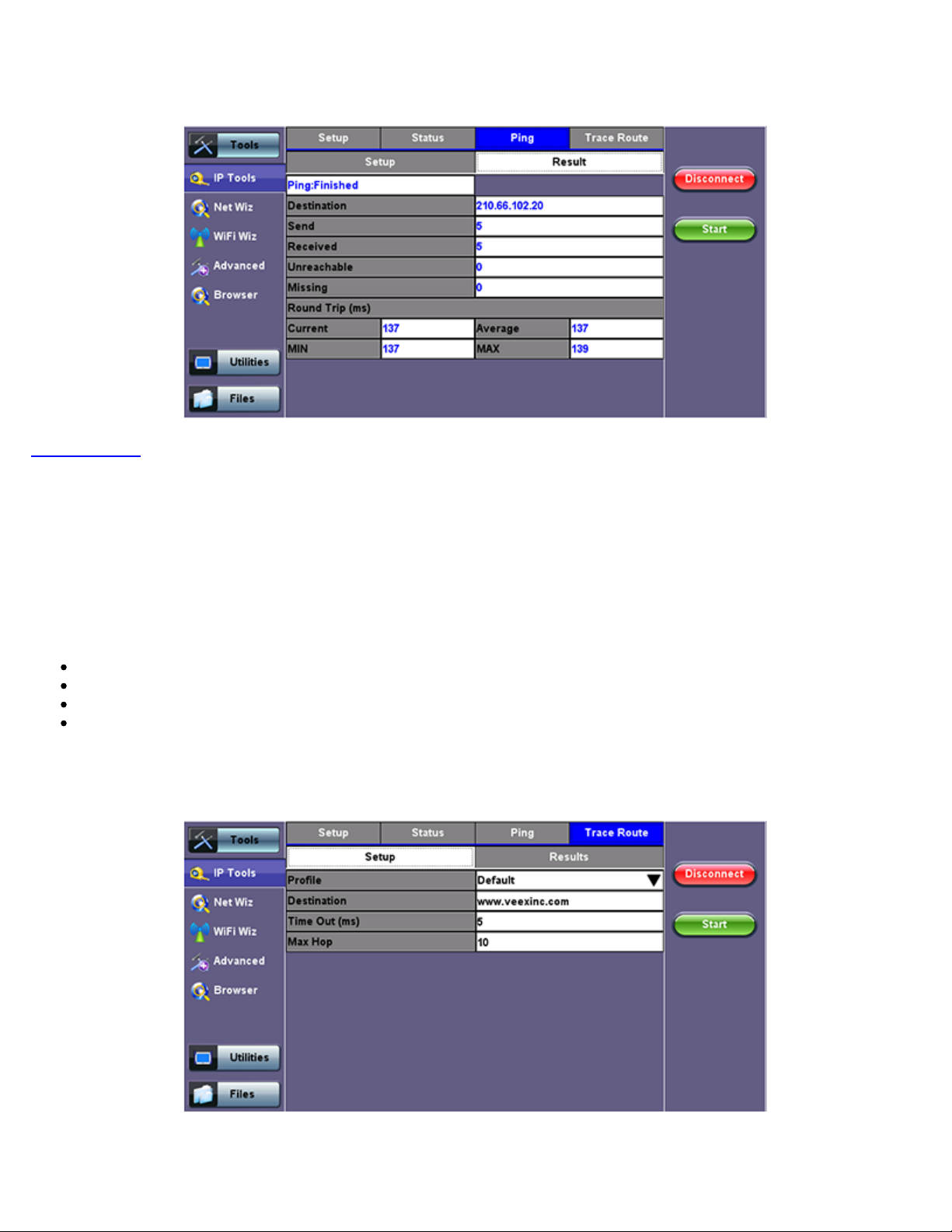
TX300s_Platform_Manual_RevB00
Page 66 of 104
Go back to TOC
7.1.4 Trace Route
Ping Result
Trace Route is a common method used to find the route to the destination IP address or URL. It is often used to identify routing
problems and unreachable destinations. All the remote IP addresses and their response times are displayed indicating possible
network congestion points.
Trace Route setup tab:
The following setup selections are available:
Profile: Delete, Save, Save as..., Default. Select Default to recall a trace route file or create a new test
Destination: Enter the IP address or URL of the network device to be detected
Time Out: Enter the maximum time allowed between an ICMP echo and response at each hop
Max Hop: Enter the maximum number of network devices the packet is allowed to transit
Once the parameters are configured, press Start to begin the test.
Trace Route Setup
Page 67
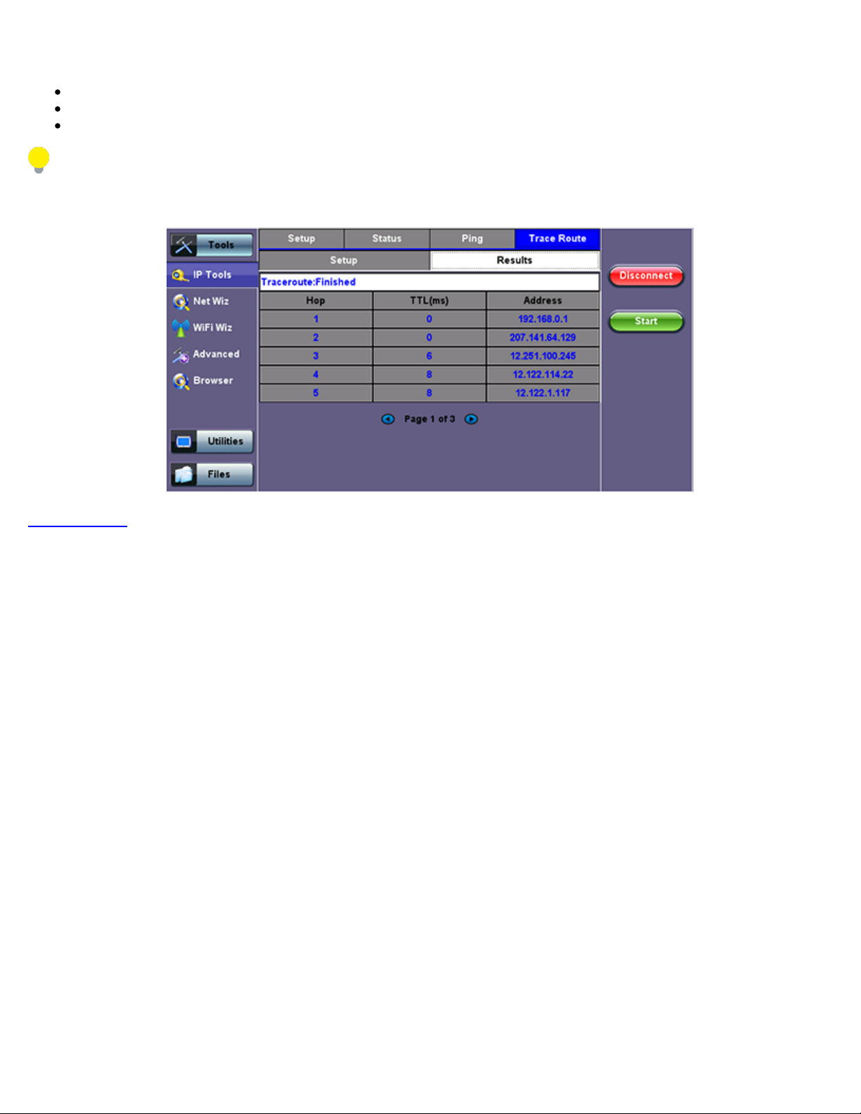
Results:
TX300s_Platform_Manual_RevB00
Page 67 of 104
Hop: Order of the routers on the route
TTL: Time to reach each router on the route
Address: Address of each router on the route
If there is no response from a particular hop, an asterisk will be displayed.
Trace Route Result
Go back to TOC
Page 68
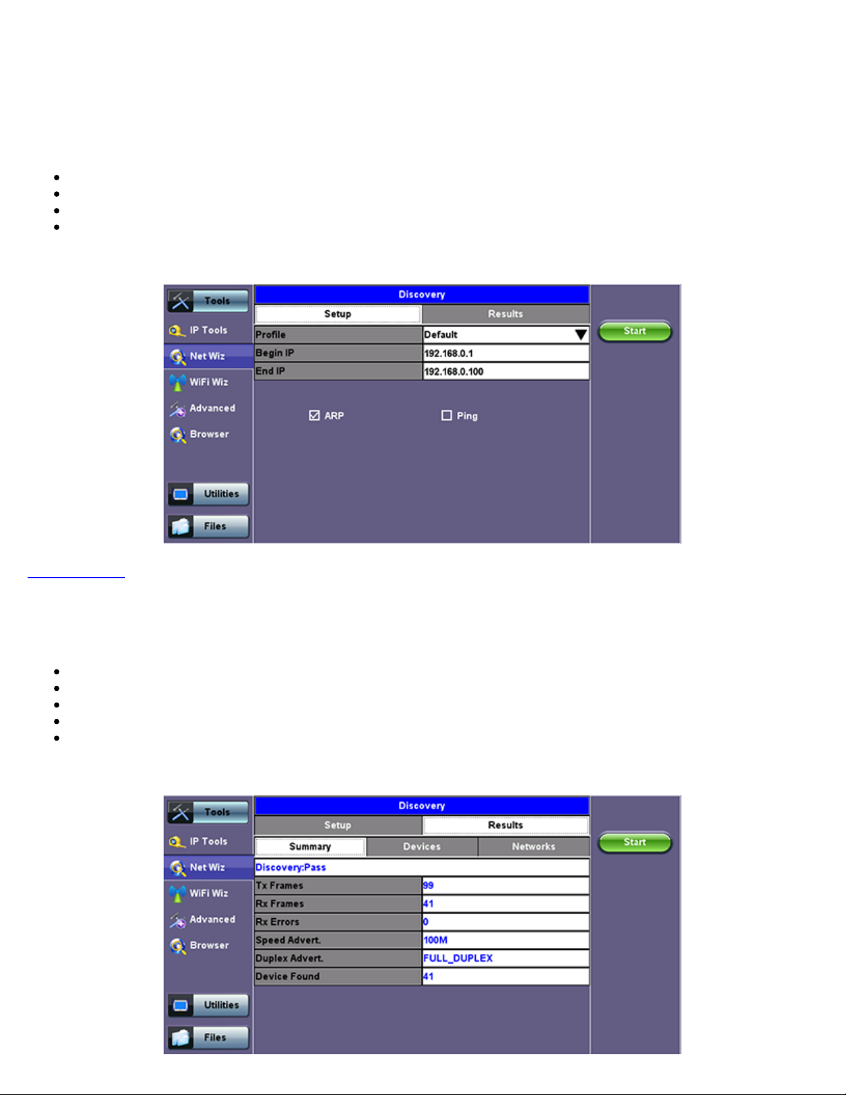
7.2 Net Wiz
TX300s_Platform_Manual_RevB00
Page 68 of 104
Net Wiz verifies the status of each IP address in the user selected range, by using ARP (Address Resolution Protocol) and ICMP
test.
7.2.1 Net Wiz Setup
Profile: Drop-down selections are Default, Delete, Save, Save As...
Begin IP: Set the start address for the desired IP range using the numeric keypad.
End IP: Set the end address for the desired IP range using the numeric keypad.
Select the test by placing a check mark in the corresponding box of any of the following: ARP, Ping.
Net Wiz Setup
Go back to TOC
7.2.2 Net Wiz Results
Summary indicates the test status and reports:
TX/RX Frames: Total number of TX (transmitted) and RX (received) frames
RX Errors: Received frames in error
Speed Advert: Speed advertised
Duplex Advert: Duplex mode advertised
Device Found: Total number of Devices and Networks found
Net Wiz Results Summary
Page 69
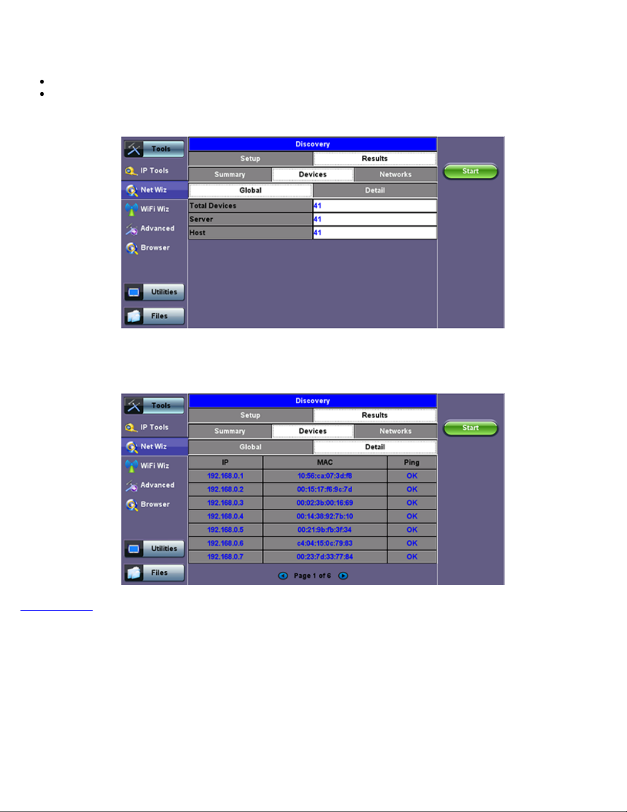
The Devices tab reports global and detailed device information.
TX300s_Platform_Manual_RevB00
Page 69 of 104
Global reports:
Total number of devices found
Number of devices (Routers, Servers, Hosts)
Net Wiz Results - Devices - Global
Detail displays the Attribute, MAC and IP Addresses, and Ping test results of each device discovered.
Net Wiz Results - Devices - Detail
Go back to TOC
Page 70
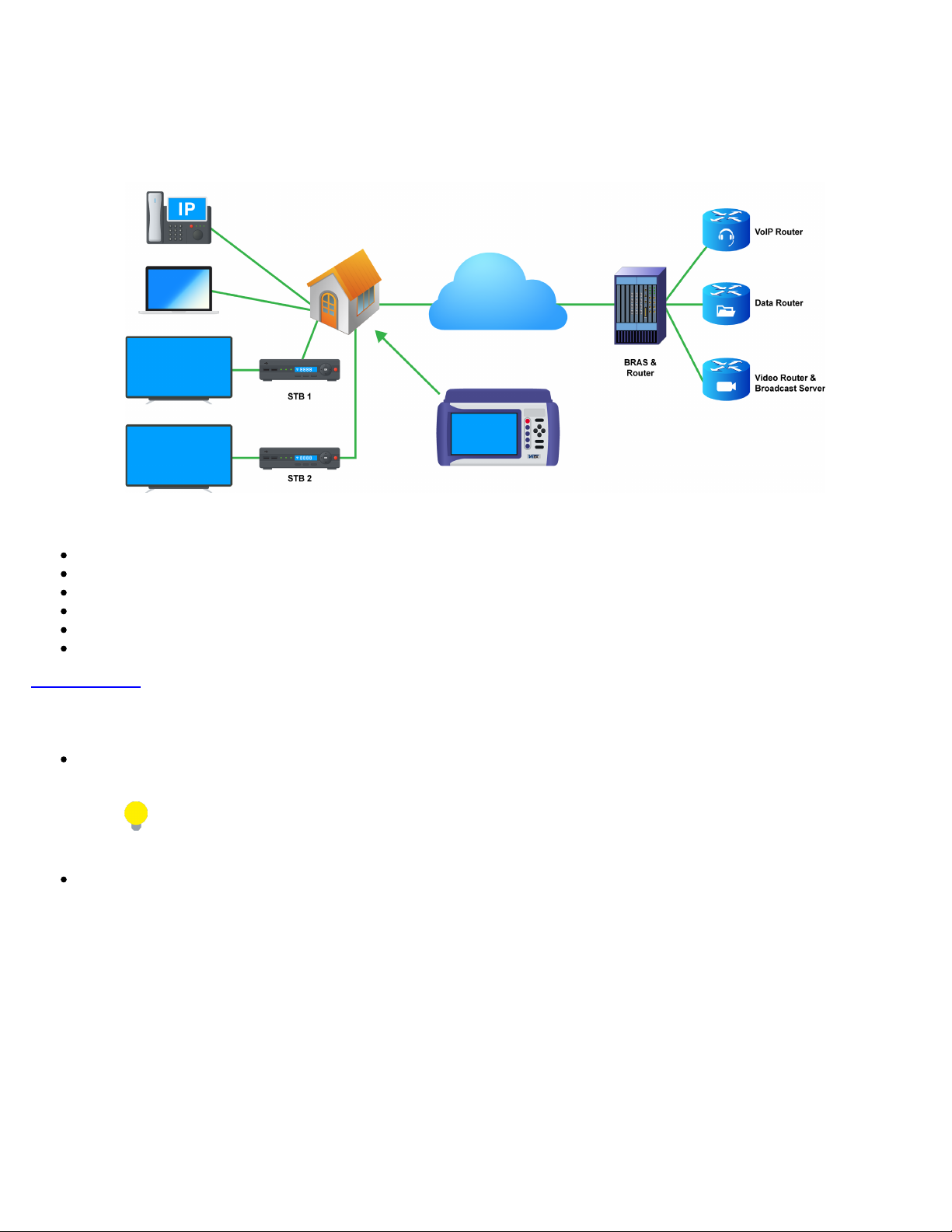
7.3 WiFi Wiz
TX300s_Platform_Manual_RevB00
Page 70 of 104
This function allows you to test wireless WiFi 802.11a,b,g,n,ac networks (based on capabilities supported by Wifi USB adaptor
provided by VeEX). A typical application is shown below.
Typical WiFi Wiz Application
The WiFi Wiz function supports:
802.11 a/b/g/n/ac standards (refer to WiFi USB adaptor provided by VeEX)
WEP, WPA, WPA2 Encryption
Scanning
SSID broadcasting and report
Signal Strength
IP Connection and Ping Test
Go back to TOC
7.3.1 WiFi Procedure
Plug the WiFi adaptor into the USB port. Allow at least 30-45 seconds for the unit to detect the wireless adaptor and for the
software driver to load.
Products support USB wireless adaptors supplied by VeEX only and have the necessary software driver built into
the test set.
Tap the Scan tab once the test set has detected the wireless USB adaptor.
Page 71
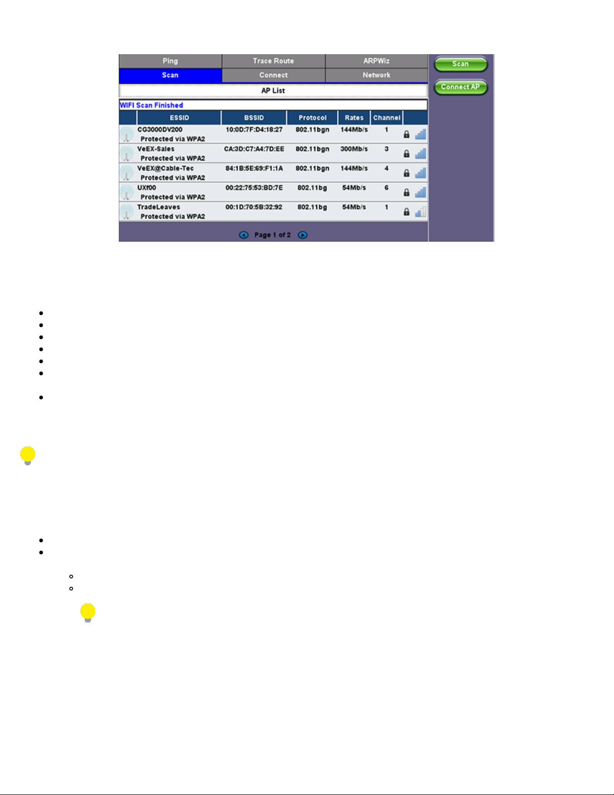
AP List
TX300s_Platform_Manual_RevB00
Page 71 of 104
The following information is displayed for each AP:
SSID name of the AP
BSSID (MAC address) of the AP
802.11 protocol version supported by the AP
Max data rate supported by the AP
AP's radio channel number
Lock symbol indicates if security is set on the AP (WEP, WPA or WPA2)
When the AP is unsecured, no lock symbol is displayed
Signal strength of the AP
WiFi Wiz - AP List
Select one of the Access Points (AP) to start a connection. If the AP is locked, a network key is required to complete the connection.
The key can either be 10 characters or 26 characters.
If the user enters the wrong network key, the test set will still connect to the Access Point, but will not be able to connect to the
web or preform the Ping test.
Once selected, an Edit Settings function button appears on the right hand side bar.
Tap on Edit Settings or Connect AP to change the Encryption Type and enter the WiFi Key.
Encryption Type: Supported encryption types include WEP, WPA, and WPA2
Key: Security phrase or password necessary to access SSID and network. Tap the Key field to enter the AP password on the
pop-up keypad.
ASCII formatting supported
The password/phrase can be hidden (Global Settings > Show Password > Yes/No).
Password/phrase can be case sensitive.
Press Apply after selecting the Encryption Type and entering the Key. If the encryption menu was accessed via Edit Settings,
press Connect AP to connect to the AP. If the encryption menu was accessed via Connect AP, the test set will connect to the AP
automatically after pressing Apply.
Page 72
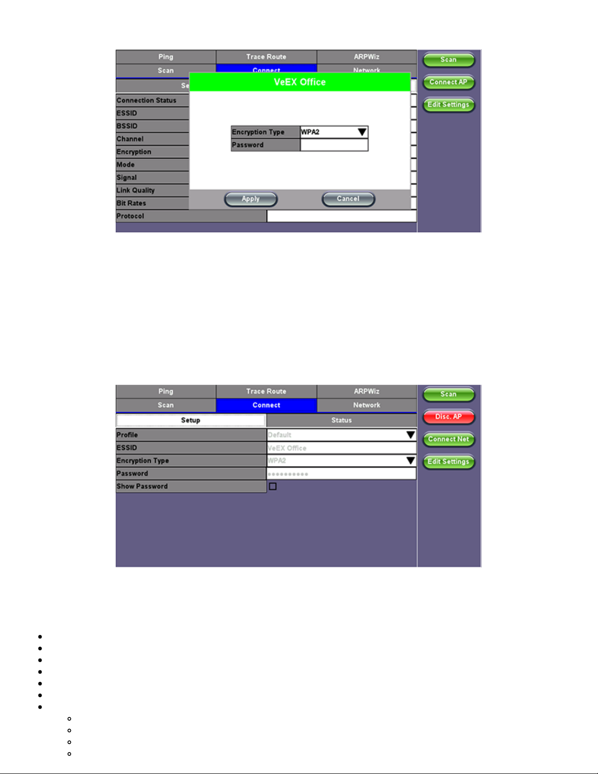
WiFi Wiz - AP Encryption Settings
802.11 protocols supported
TX300s_Platform_Manual_RevB00
Page 72 of 104
Connect
The Setup Tab displays the Profile, ESSID, Encryption Type and Password.
WiFi Wiz Connection Setup
Status
The Status Tab displays the following information on the connection:
Connection Status
ESSiD: Name connected to
BSSiD: MAC address of wireless router/device connected to
Channel: WiFi Channel # connected to
Encryption: Encryption type
Mode
Signal:
Radio signal level (dBm)
Link quality score
Max data rate
Page 73
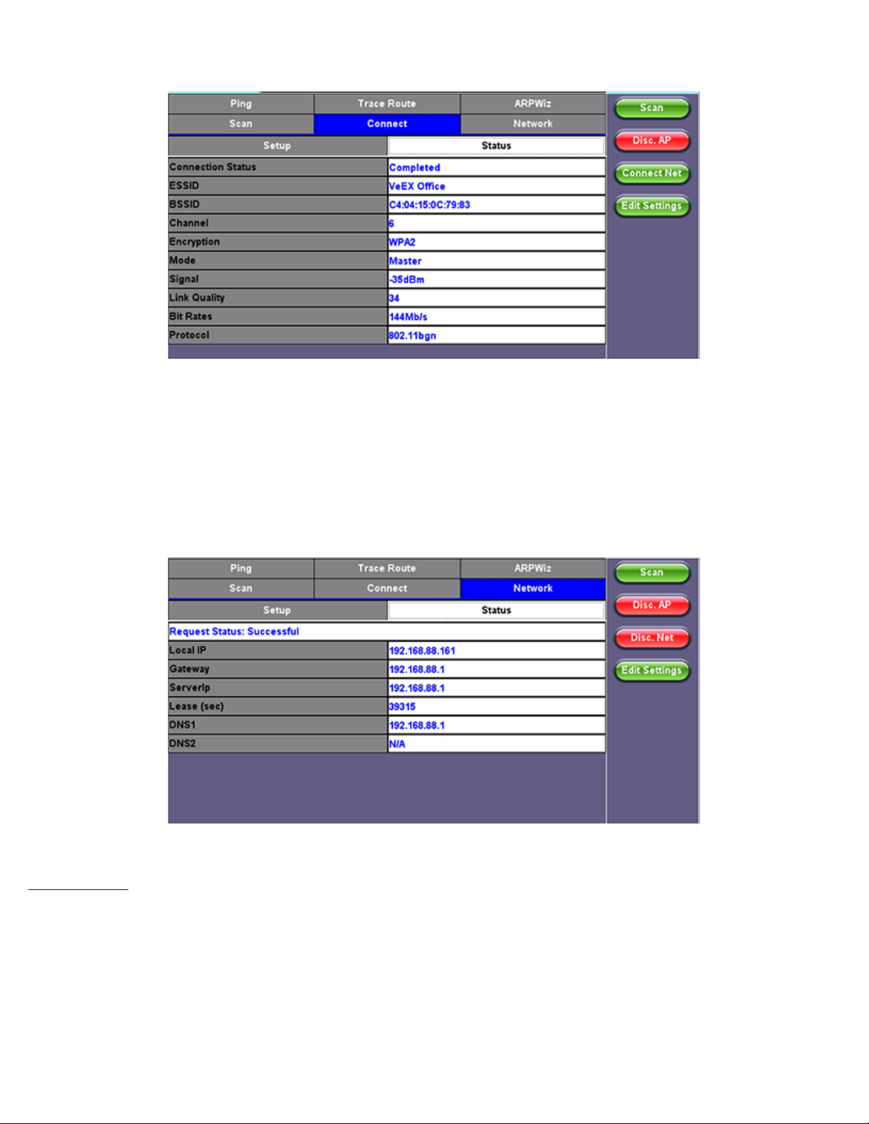
WiFi Wiz Connection Status
TX300s_Platform_Manual_RevB00
Page 73 of 104
After a successful connection to the Access Point press Connect IP to obtain an IP address and access the additional IP tests like
Ping, Trace Route etc.
Go back to TOC
WiFi Wiz Connect IP
Page 74
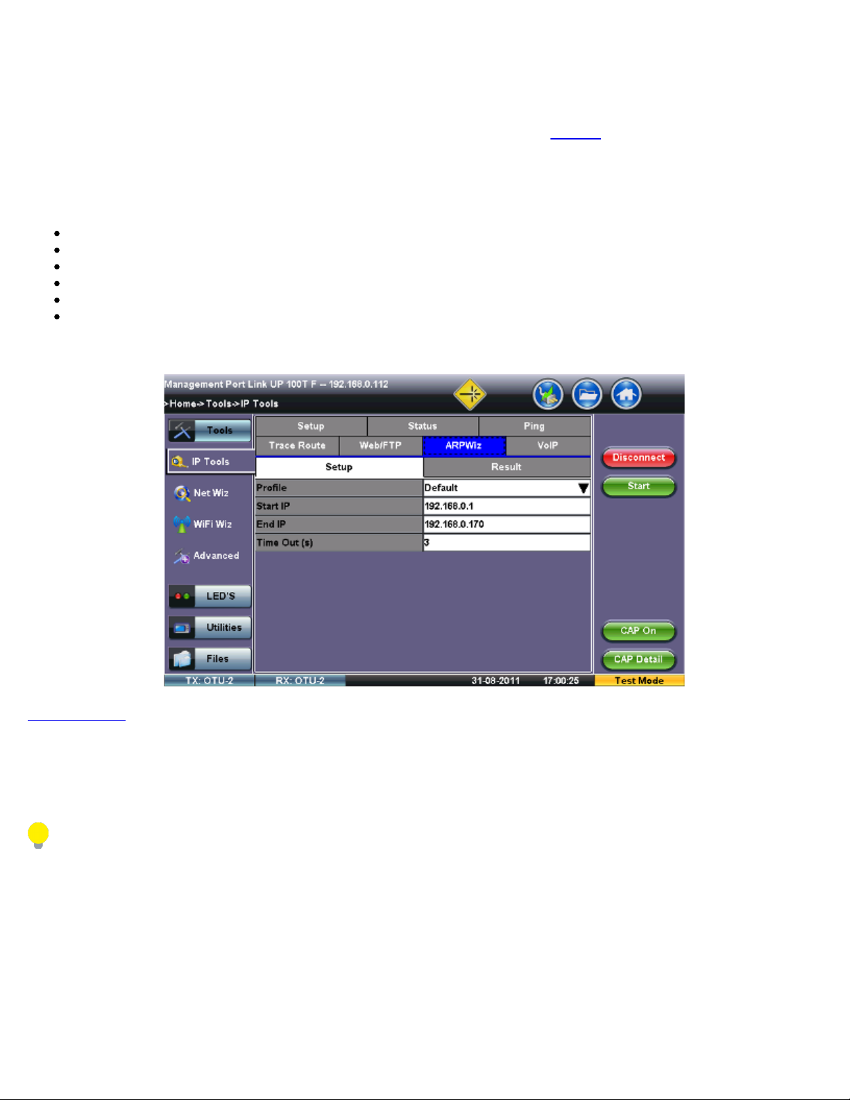
7.4 ARP Wiz
TX300s_Platform_Manual_RevB00
Page 74 of 104
ARP Wiz uses the Address Resolution Protocol (ARP) to verify the status of each IP address in a user-selectable IP range. ARP is
the standard method for finding a host's hardware address when only its network layer address is known. In other words, ARP is
used primarily to translate IP addresses to Ethernet MAC addresses. ARP is defined in
Setup
Configure the following parameters:
Profile: Drop-down selections are Default, Delete, Save, or Save As...
Start IP: Starting IP Address
End IP: Ending IP Address
Time Out(s): Range from 1-99 seconds. Input using the numeric keypad
Press Start.
The test will continue to run until the user presses Stop. A finished status indication will display when the test finishes.
ARP Wiz Setup
RFC826.
Go back to TOC
Result
The MAC addresses associated with active IP addresses in the range are displayed. If no MAC address is associated with the IP
address, a FAILED status is displayed.
ARP Wiz uses the ARP protocol abd can only work within the same subnet as the IP address provided to the test set in IP
Status.
Page 75
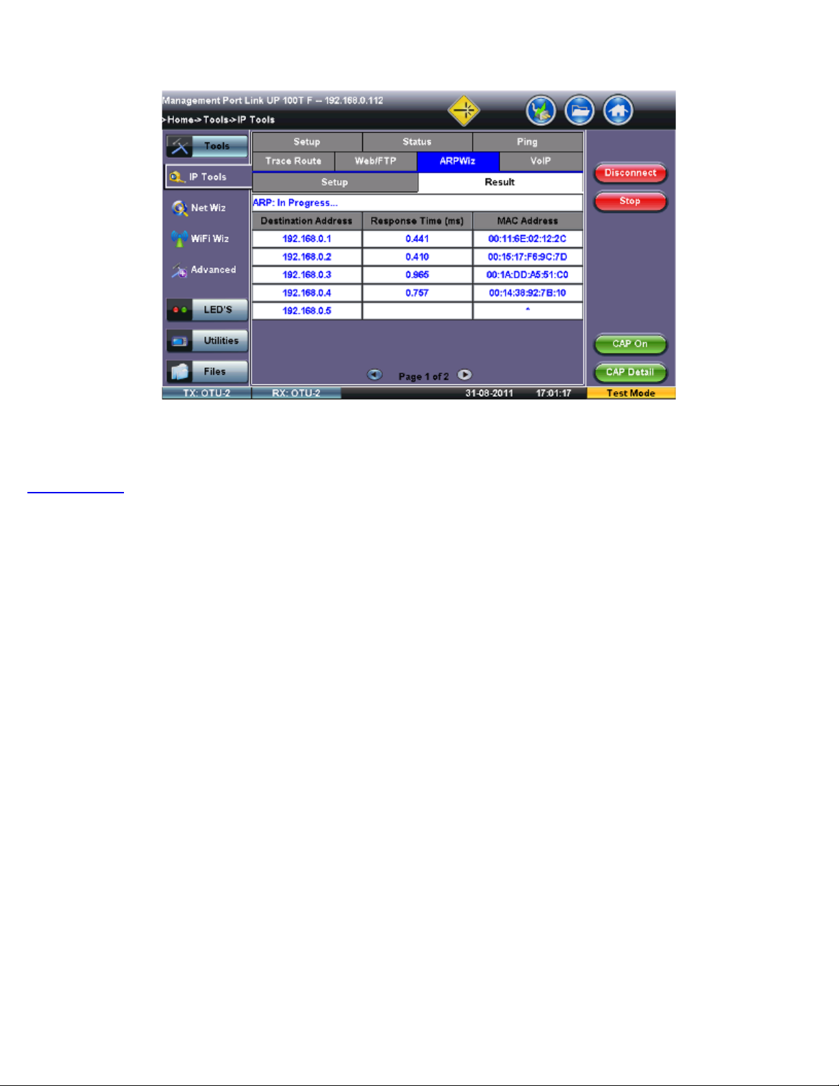
ARP Wiz Result
TX300s_Platform_Manual_RevB00
Page 75 of 104
Go back to TOC
Page 76
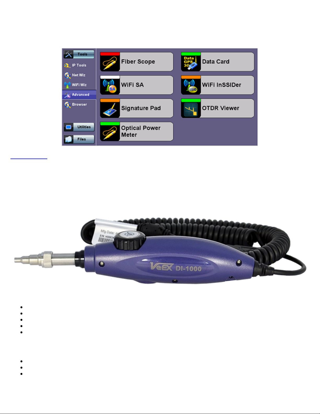
7.5 Advanced Tools
TX300s_Platform_Manual_RevB00
Page 76 of 104
Go back to TOC
7.5.1 Fiber Scope
Advanced Tools
The Fiber Scope Inspector is an ideal tool for checking fiber optic connectors for dirt and end face quality. The handheld probe
design enables easy inspection of patch cords and difficult to reach bulkhead or patch panel connectors. Clear images are displayed
on the V300 products for immediate analysis and can be saved for record keeping.
Fiber Scope
Key features include:
Optical connector end face inspection
Easy to change adaptor tips
Multi mode and single mode fiber patch cords
Sharp images displayed on VeEX V300 products
Visual comparison mode of saved image
The ISO/IEC 14763-3 standard for Testing Optical Fiber Cabling specifies visual standards for connector end face inspection with a
fiber microscope. The ISO-related standards and general industry practices recommend the following:
Markings on the core or damage to the cladding close to the core are unacceptable
Slight scratches and small pits on the cladding away from the core are, however, acceptable
Cracks are not permitted in neither core or cladding
Equipped with 400x magnification, the VeEX Fiber Scope Inspector is well suited for general installation and maintenance checks on
both single mode and multi mode fiber types. Contamination or damage that cannot be viewed at this magnification is unlikely to
impact practical connector performance, thus, it is an ideal tool for patch cord inspection, optical laboratory or field test applications.
Page 77

Lightweight construction and the ergonomic positioning of the rotary focus dial enables one-handed operation and fast viewing,
leaving one's hand free to move the connector under test as needed. Interchangeable screw-on adaptors are available for most
TX300s_Platform_Manual_RevB00
Page 77 of 104
modern optical connectors, while the probe design blocks any hazardous infrared light from reaching the operator, resulting in
completely eye-safe operation.
Go back to TOC
7.5.1.1 Automatic Focus Detection and Analysis
In the past, fiber connector end-face inspection not only required a good Fiber Microscope (Fiber Scope), but certain amount of
knowledge and hand-eye dexterity from the user. Results were prone to inconsistencies, subject to interpretation and PCs were
required for post analysis against the criteria set forth by the IEC 61300-3-35 Sect 5.4 standard.
VeEX has made the task easier, faster and foolproof, with the introduction of its patent-pending revolutionary Automatic Focus
Detection technology. Turning ordinary digital fiber scopes, like DI-1000, into accurate semi-automated inspection systems, all with
the help of TX300s, FX300, RXT-1200 or SunLite OTDR test sets.
Instead of adding the extra complexity, fragility, cost, size and weight of other electromechanical focusing systems currently
available in the market, VeEX’s auto focus detection technology still relies on the fast response and finesse of human hands, but
leave the focus assessment, image capturing and analysis to the test set. Users could even try with their eyes closed and still
achieve a perfectly focused image of the connector end-face in a few seconds. Moreover, users would still remain in control during
non-trivial scenarios requiring human dexterity and ingenuity.
Go back to TOC
7.5.1.2 Main Advantages of Automatic Focus Detection
Investment protection (no need to replace existing scopes, like DI-1000, with a more expensive ones)
It’s a simple software option upgrade to the test set
Much faster focus, acquisition and analysis, compared to slow electro-mechanical auto-focusing scopes
Robustness: Less moving parts and no internal motors makes a better choice for field applications
No training necessary, yet get it right every time
Smaller scope size
Report generation (HTML and PDF)
The test set detects when the image has reached optimal focus level, automatically freezes the picture, captures the image
and runs the IEC 61300-3-35 analysis
No need to move hands or press any buttons (movement and vibration are common causes of focus loss)
No PC required for image acquisition or Pall/Fail analysis
Go back to TOC
7.5.1.3 The Importance of Fiber Connector Inspection
Dirty or scratched connectors introduce loss, increase ORL and/or damage other connectors (Loss becomes more critical at higher
data rates). End-face contamination is a leading cause of fiber link failures in data centers, corporate networks, MSOs and Telecom
environments.
Fiber Inspection Scopes provide a magnified image of the fiber optics connector’s End Face, focusing on the contact areas (prone to
loss or damage by mating). Images, visual inspection and automated tools are often used to grade the health and cleanliness of
connectors, after polishing or cleaning and before being used.
Go back to TOC
7.5.1.4 Fiber Connectors and Test Gear Vulnerabilities
Opposed to the permanent or semi-permanent connections often found in network environments, “promiscuous” Test Equipment
and their patch cords connect to multiple devices on a daily basis, increasing the chances to damage or get damaged. Extra care
must be taken, not only to avoid potentially expensive damage, but to make sure that any tests and their results remain valid. Bad
fiber or dirty/damaged connectors can result in false anomalies, defects or errors, even expensive repairs.
Go back to TOC
Page 78
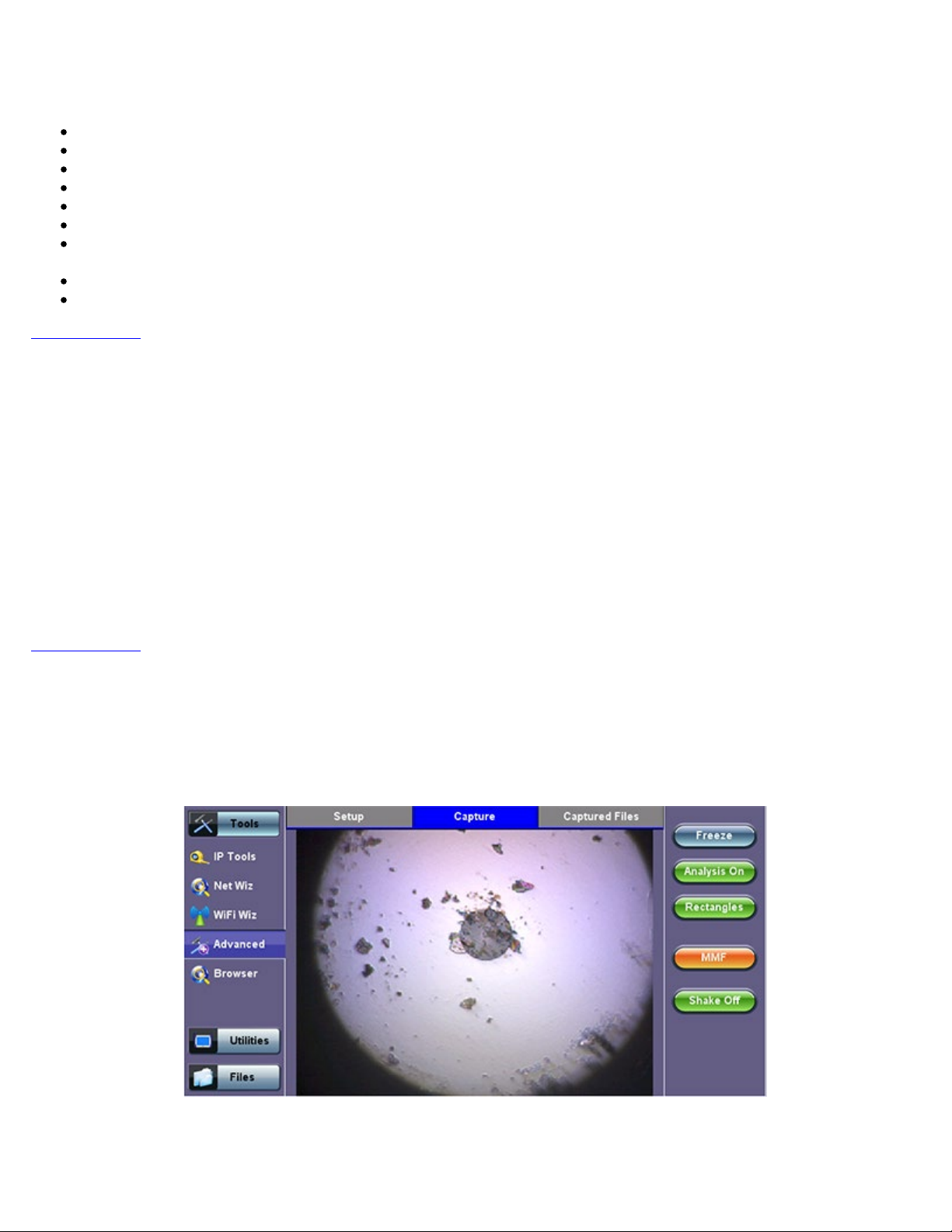
Freeze: Allows users to manually freeze the image in the desired view. If the optional Auto Focus Detection feature is enabled, the
TX300s_Platform_Manual_RevB00
Page 78 of 104
7.5.1.5 About the DI-1000 Fiber Inspection Scope
Digital Fiber Inspection Probe
Native USB 2.0 (no adapters required, no image degradation)
Compatible with existing UX400, TX300s, FX300, RXT-1200 and SunLite OTDR
Precise and stable single-finger focus knob for one hand operation
Blue light source for better contrast
400X magnification
Interchangeable tips – Most commonly used tips are available (FC, SC, LC, ST, MTP, E2000, including PC, APC, 60° angled
tips, among others)
Compatible with VeEX test sets offering built-in Auto Focus-Detection & Analysis
Ergonomic design
Go back to TOC
7.5.1.6 Fiber Connector Inspection Setup
The Setup tab allows basic settings:
File Prefix: String of alphanumeric characters to be prepended at the beginning of the file name, every time the results are saved.
For example Fiber0239-.
Starting #: Every time a result is saved, this suffix number will automatically increment. Users can manually enter the initial value
here.
Auto Freeze: This is amount of time the optional Auto Focus Detection feature will look for a stable in-focus image before
automatically freezing the image and starting an analysis. Select Never, if manual capture or real-time analysis is desired. Auto
freeze comes handy when both hands are tied (e.g. one holding the connector and the other holding the probe, or working on a
pole).
Scope Mode: Use Local for USB fiber inspection scopes that are directly attached to the test set. Use Remote if the probe is
attached to a wireless transmitter using Wi-Fi connection.
Go back to TOC
7.5.1.7 Capture Tab (View)
The Capture tab is the main user interface for the connectors’ face inspection and analysis. It presents a real-time view of the
connector’s end face allowing users to align and focus.
Fiber Scope - Capture tab
Important! The soft buttons in the action bar (right side of the screen) do not indicate the current state or setting, they indicate the
action that would take place if pressed. For example, if user taps on the “Analysis OFF” button, the analysis function is turned OFF
and the button toggles to show “Analysis ON”. These soft buttons should be interpreted as “Go to…”
Page 79
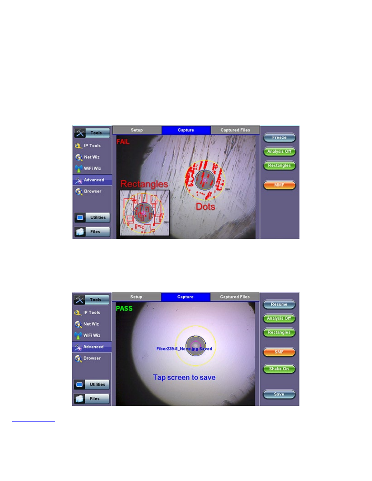
test set will automatically freeze the image when the image comes into focus. Once the image is frozen, users can tap on the image
to save it.
TX300s_Platform_Manual_RevB00
Page 79 of 104
Analysis ON/OFF: Turns the optional auto-analysis feature ON and OFF. If turned ON, the test set automatically analyzes the
image in real time. If the markers get in the way of seeing the picture details, users can turn this feature OFF and perform manual
analysis.
Dots/Rectangles: They are two ways of highlighting the different impurities found in the face of the connector. The dots tightly
contour each individual anomaly, capturing its area. In some cases users may want to see impurities or scratches that are otherwise
covered by the dots, so rectangles are used in this case to highlight the anomaly and still keep them visible. The selection between
dots or rectangles does not affect the area calculation of the Pass/Fail results; they are just the operator’s choice.
Save: The Save button appears after freezing an image. It performs the same action as tapping on the screen to save the current
image. Use the >Utilities >Files function to View the report, export to PDF format and copy to USB.
MMF/SMF: Selects the type of connector/fiber to be analyzed and loads the correct Pass/Fail mask. Please note that the label in the
button DOES NOT indicate the current mask type. It indicates that the mask would be changed to if activated.
Shake ON/OFF: Turning the Shake ON may help in situations when the image is not very stable, such as inspecting a female
connector or bulkhead.
Go back to TOC
7.5.1.8 Captured Files Tab
This section of the user interface lists all the connectors’ end face images that have been captured with the fiber inspection
microscope. Users can add “Before” and “After” identifiers or reminders when comparing images before or after cleaning or
polishing.
Page 80
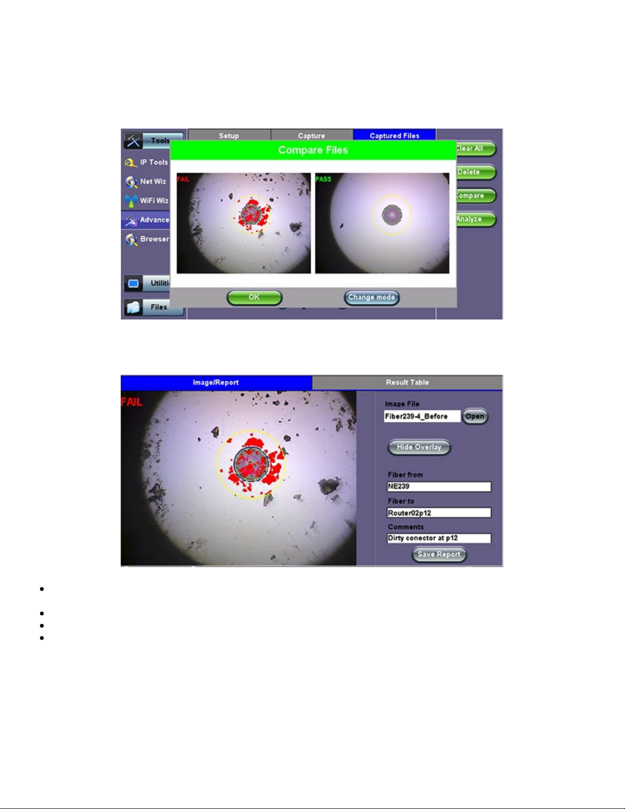
Clear All: Deletes all the image files in the Captured Files list.
TX300s_Platform_Manual_RevB00
Page 80 of 104
Delete: Deletes any selected files from the Captured Files list. Use the check-boxes to select.
Compare: Compares two images, for example, ones taken before and after cleaning. Use the check-boxes to select any two image
files and then tap on the Compare soft button. Use the Change Mode button on the comparison window to enable and disable the
analysis overlay.
Analyze: This soft button opens a more detailed analysis and report generation. Use the check boxes to select the images to be
analyzed.
Image File: shows the name of the picture currently being displayed. Use the Open button to navigate, select and load any
other file.
Show/Hide Overlay: Enables or disables the mask, anomalies identification and analysis.
Finer From/To: User customizable labels to identify the fiber under test.
Save Report: Generates a full report including a table with measurements and images. Use the >Utilities >Files function to
View the report, export to PDF format and copy to USB.
Page 81
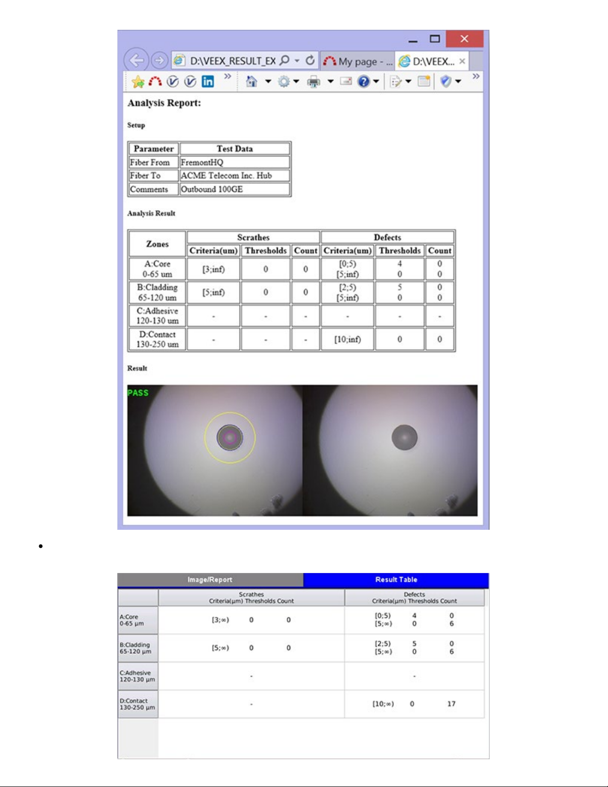
Results Table: Shows the defects and scratches count by sizes and position, used for the evaluation of the Pass/Fail criteria,
TX300s_Platform_Manual_RevB00
Page 81 of 104
according to the IEC 61300-3-35 standard.
Page 82
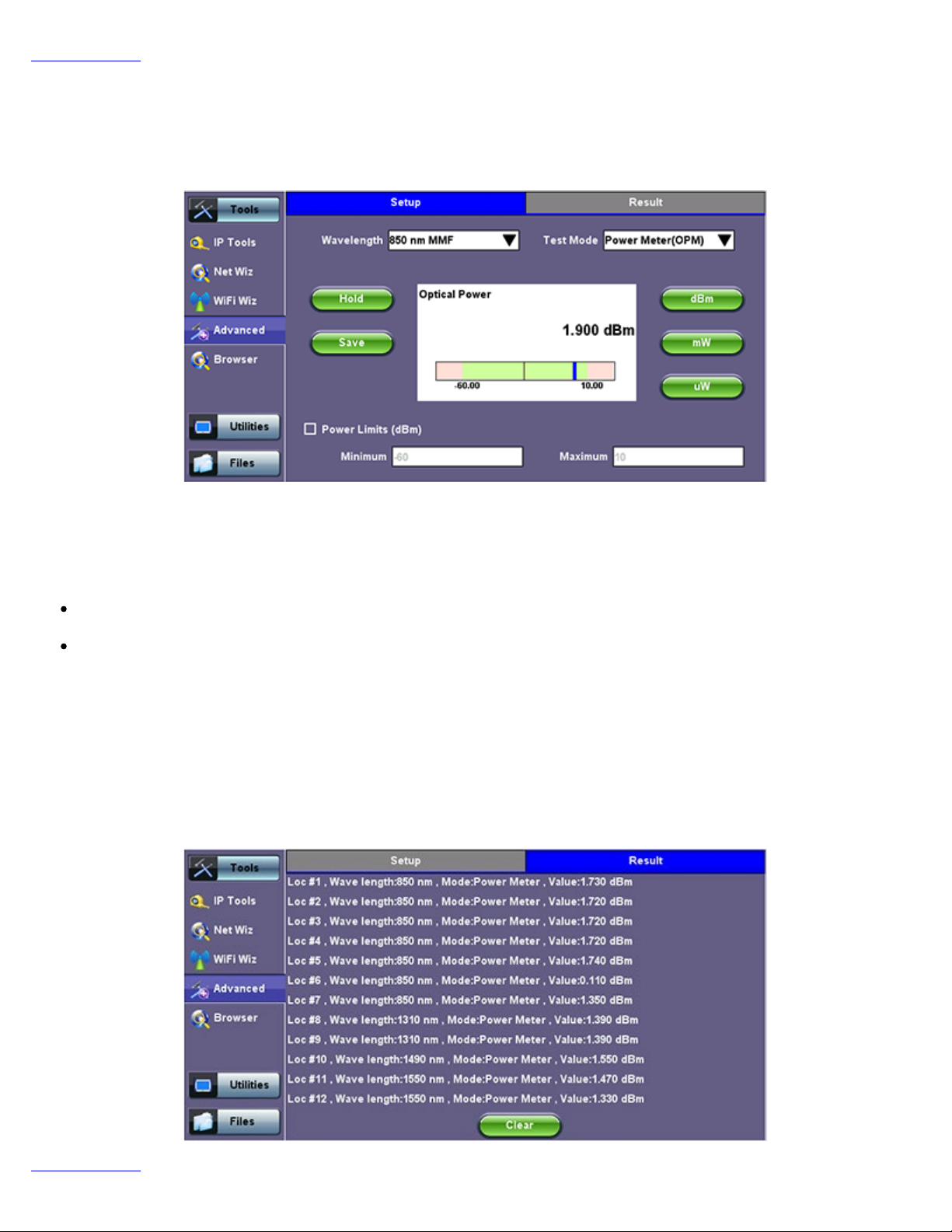
Go back to TOC
TX300s_Platform_Manual_RevB00
Page 82 of 104
7.5.2 Optical Power Meter (OPM)
This function works in conjunction with Optical Power Meter dongles (USB), such the optional UPM-100.
Insert the OPM dongle to on of the test set’s USB port before launching this application.
Optical Power and Loss Measurements
Wavelength: This pull-down menu provides a list of calibrated wavelengths to match the signal being measured.
Test Mode: Allows users to select between Power or Loss measurements.
In Power Meter mode the test set presents the direct power readings, which are displayed in dBm, mW or uW units. Users
can perform the conversions by using the button on the right side of the reading.
In Loss Meter mode the test set reports the difference in power readings between the Laser Source (LS) output being used
and what is currently present at the connector after being attenuated by the fiber. The results are presented in dB. Loss meter
requires to be referenced (calibrated) to the Laser Source output. You must connect the LS to the OPM dongle using a short
patch cord and tap on the Reference button to record the 0dB point. Then that LS can be connected to the far-end of the fiber
to measure the loss.
Hold: Freezes the last power or loss reading on the screen
Save: Records instantaneous power or loss readings in the Result tab. This is useful when measuring multiple fibers or testing one
fiber with multiple wavelengths. Up to 12 measurements can be logged in the Result tab. You must use the 1 button to save these
results.
Go back to TOC
Page 83
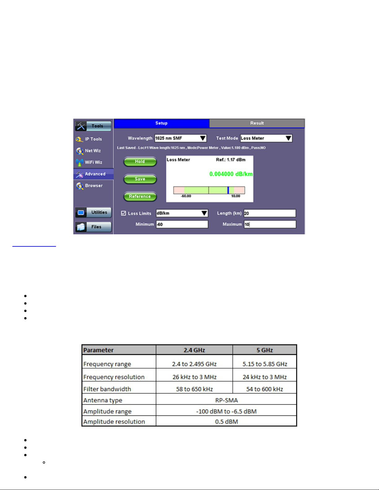
7.5.2.1 Setting Pass/Fail Limits
The WiFi Analyzer is a compact and portable USB dongle that plugs into the USB 2.0 port of the V300 series
TX300s_Platform_Manual_RevB00
Page 83 of 104
Whether measuring optical power or loss, there are always power input limits (saturation and Loss) or attenuation allowances that
determine whether the fiber cable meets the requirements for the desired application or network elements.
Power Limits (dBm): When check-box is ticked, users can enter the Minimum and Maximum power levels allowed for the
application (e.g. in line with the transceiver’s dynamic range). If the power reading falls beyond those limits, the power measurement
reading will turn red.
Loss Limits: Similar to power limits, user can set Minimum and Maximum amounts of optical power loss that are acceptable for the
application or specified for the cable or installation. User can simply specify the total amount of attenuation in dB. Alternatively user
can select the dB/km or dB/mi if the results are being compared against cable specifications. In this case, enter the length of the
cable under test for the test set to make the conversion.
Go back to TOC
7.5.3 WiFi Spectrum Analyzer
WiFi SA is a portable spectrum analyzer on a USB dongle that displays all RF activity in the WiFi bands (e.g.,s wireless networks,
cordless phones, microwave ovens, Bluetooth devices, etc.). It offers the following capabilities:
Helps determine the best available WLAN channels quickly for optimal performance
Helps to visualize and locate RF signals in the 2.4GHz and 5GHz spectrums
Discover and remedy competing access points
Optimize WLAN networks by locating and eliminating interference sources
WiFi SA Specifications
Supports 802.11a/b/g/n networks
Supports both 2.4 GHz and 5 GHz bands
Equipped with RP-SMA antenna jack
Allows user to replace standard external Omnidirectional antenna with a higher gain or directional antenna as
needed
Page 84
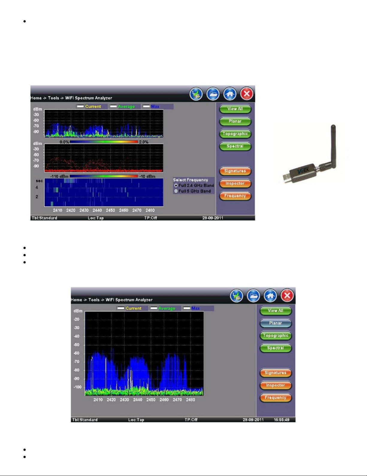
The WiFi SA test application menu is located in the Tools/Advanced Tools menu
TX300s_Platform_Manual_RevB00
Page 84 of 104
WiFi SA Display Summary WiFi Analyzer USB dongle
Display Summary
Planar view: Reports current, average, and maximum signal amplitude for each wireless frequency
Topographic view: Emphasizes which frequencies are the busiest across the entire spectrum
Spectral view: Historical view of wireless spectrum use at a point in time
WiFi SA - Planar View
Planar View
Traditional Spectrum Analyzer view with Max, Average, and Current results
Displays RF activity in real time and tracks average and max values over a given period
Page 85

Topographic View
TX300s_Platform_Manual_RevB00
Page 85 of 104
Similar to a density map - plots frequency versus amplitude
Uses a special color scheme to assign colors to frequency amplitude points and to identify how often a particular coordinate
is recorded
Great resource for identifying devices with very low duty cycles
Leaving it running will give a good indication of the typical local network conditions
WiFi SA - Topographic View
Spectral View
Waterfall type view across the whole band - graphs amplitude levels over time
Uses color to pick out the relative signal strength at each point in time
Great tool for troubleshooting intermittent problems, since it highlights devices that are perhaps emitting only short bursts of
noise
WiFi SA - Spectral View
For example - discover microwave oven in the kitchen interfering with WLAN
Page 86
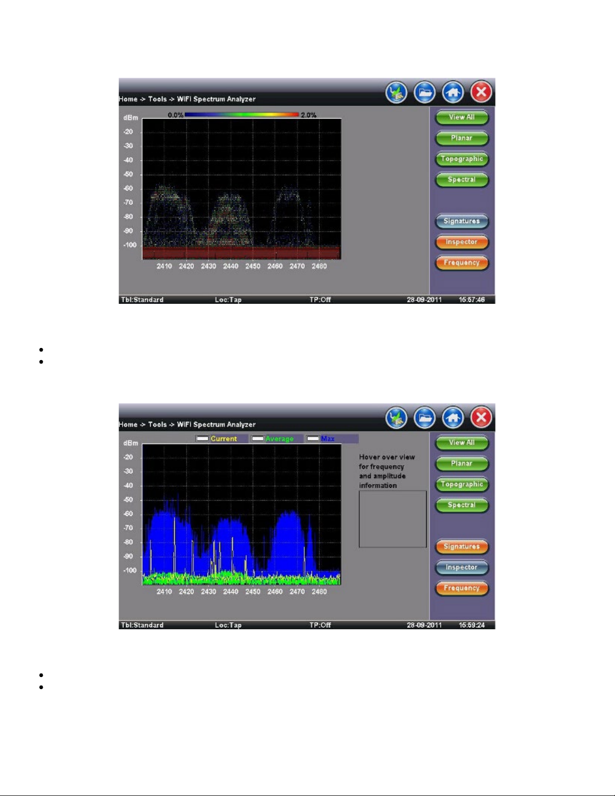
TX300s_Platform_Manual_RevB00
Page 86 of 104
Signatures
WiFi SA - Signatures
The Signatures button presets are available to identify unknown sources of RF activity (e.g., microwave oven)
Select a device in the sidebar and click the pattern in the Topographic view to identify a device
WiFi SA - Inspector
Inspector
The Inspector button setup allows the user to measure the frequency of the RF activity or interference of interest
When selected, a prompt and result box appears
Page 87
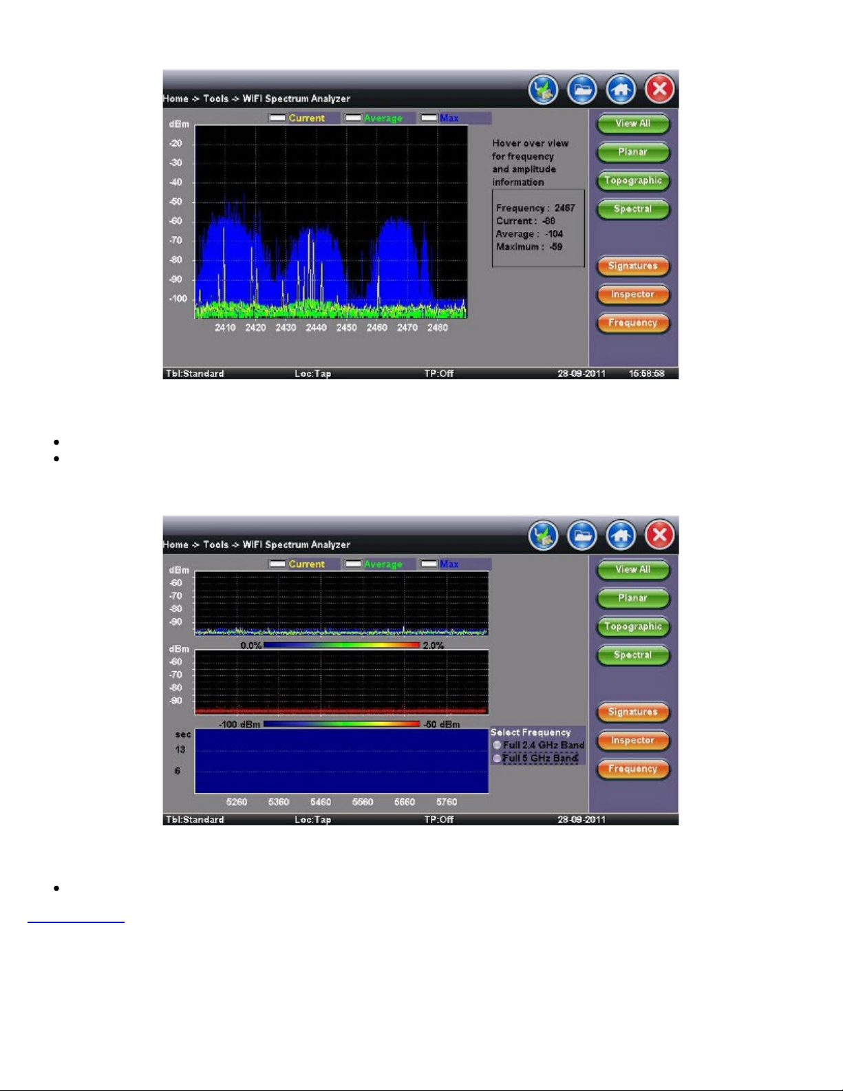
WiFi SA - Inspector - Result
Inspector Button - Result
TX300s_Platform_Manual_RevB00
Page 87 of 104
Identifies frequency and amplitude
Current, Average, and Maximum amplitude values provide an indication of level fluctuation over measurement period
Frequency
This button allows the user to select frequency band for testing
WiFi SA - Frequency
Go back to TOC
7.5.4 Data Card
To establish an IP connection using a data card, please make sure that the data card is connected on the USB port. Note that only
datacards provided by VeEX are supported and have the driver necessary for connection. The Data Card icon, as shown below, will
appear at the bottom of the screen.
Page 88
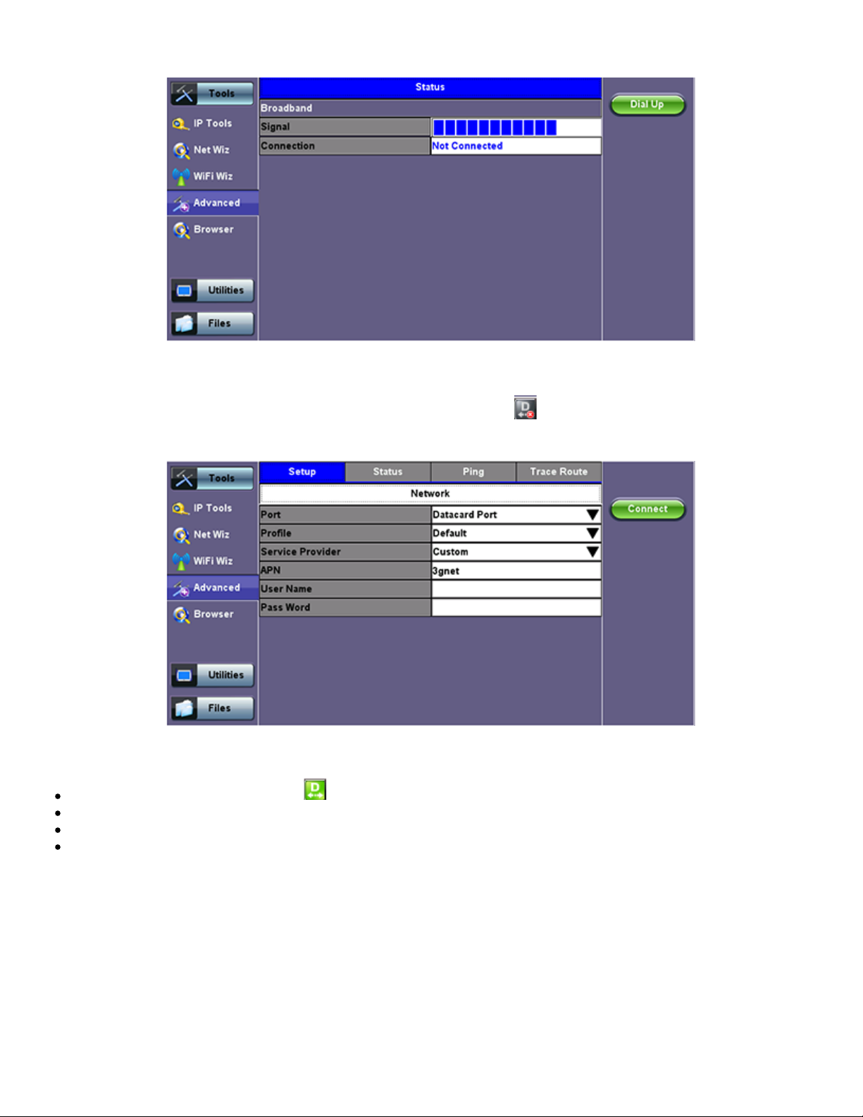
Data Card - Setup
TX300s_Platform_Manual_RevB00
Page 88 of 104
1. Press the Dial Up key
2. In the IP Tools Setup menu, the Port will be displayed as "Datacard Port." The D for Data icon in the bar on the lower end of
the screen will have a red cross to show that datacard is not connected Select the configuration parameters, then press Connect.
Once a connection has been established:
The D for Data in the icon turns green .
The connection details are displayed in the IP Tools Status tab (shown below)
It will automatically reconnect if the test set is powered off/on and you are in a good reception area
It will automatically reconnect if you enter a bad cell area and return to a good one
.
Page 89
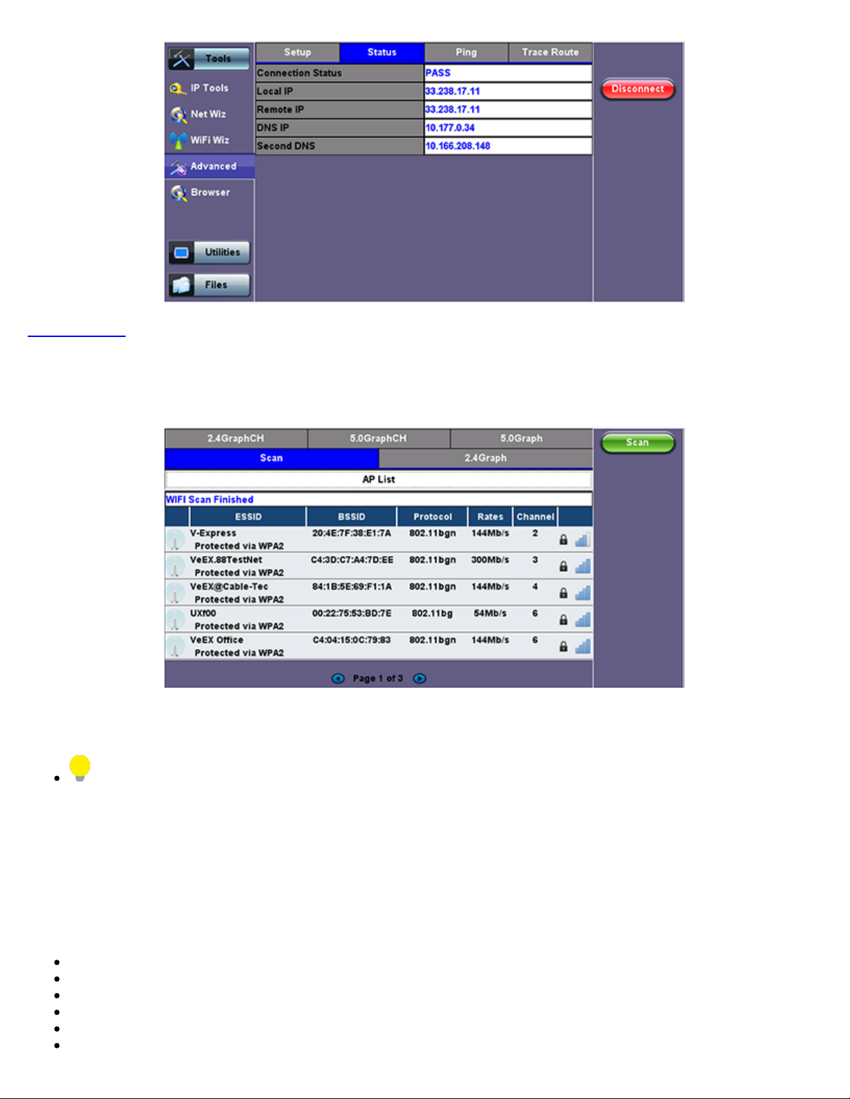
Go back to TOC
TX300s_Platform_Manual_RevB00
Page 89 of 104
7.5.5 WiFi inSSIDer
WiFi inSSIDer Home
1. Plug the WiFi adaptor into the USB port. Allow at least 30-45 seconds for the unit to detect the wireless adaptor and for the
software driver to load.
Products support USB wireless adaptors supplied by VeEX only and have the necessary software driver built into the test
set.
The WiFi InSSider supports 2.4GHz and 5.0GHz Bands. The home screen has tabs to display test results for both frequency bands
and also for graphical presentation of results for both.
2. Tap the Scan button on the right side of the screen.
After the scan is completed, the unit displays the list of access points (AP) detected in the 2.4 GHz and 5GHz bands.
The following information is displayed for each AP:
SSID name of the AP
BSSID (MAC address) of the AP
802.11 protocol version supported by the AP
Max data rate supported by the AP
AP's radio channel number
Lock symbol indicates if security is set on the AP (WEP, WPA or WPA2).
When the AP is unsecured, no lock symbol is displayed
Page 90
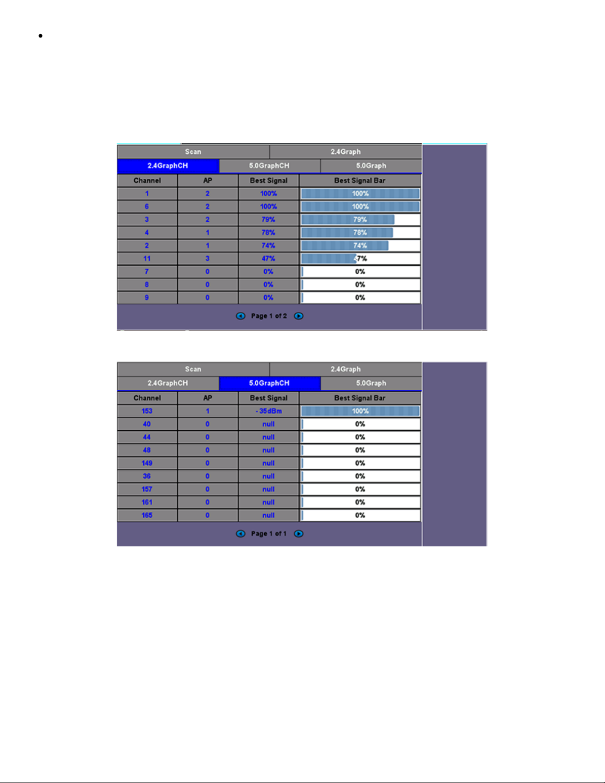
Signal strength of the AP
TX300s_Platform_Manual_RevB00
Page 90 of 104
Access Points in the 5.0GHz spectrum can only be displayed if the VeEX USB Wifi adapter supports 802.11a/n or 802.11 a/n/ac.
Refer to the USB Wifi adapter specifications.
3. Use the 2.4GHz GraphCH and 5.0GraphCH tabs to view the number of Access Points detected for each channel in the 2.4GHz
and 5GHz bands and the strength of the strongest AP's signal for each channel.
2.4GHZ Channel
5GHZ Channel
4. Tap the Graph tab of the respective Channel to view the results in a graphical presentation.
Page 91
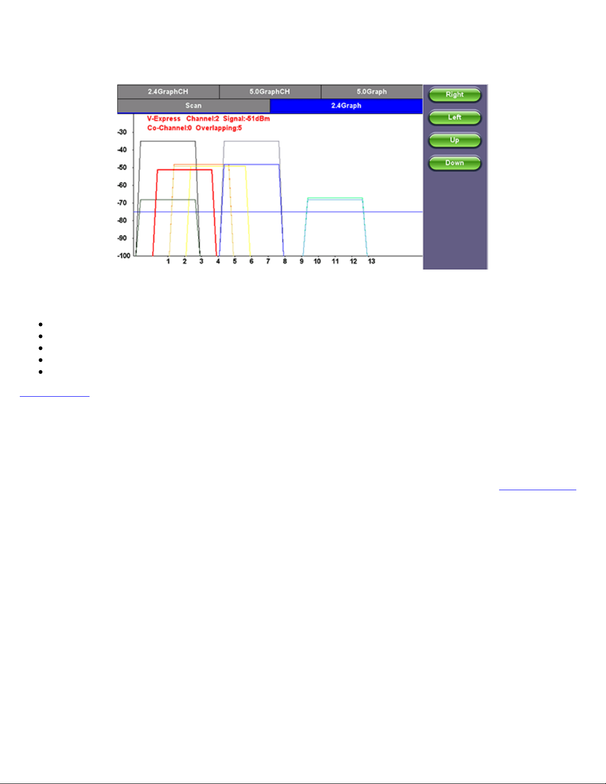
TX300s_Platform_Manual_RevB00
Page 91 of 104
Graph
Use the Right/Left/Up/Down function keys or the arrow keys on the unit's keypad to navigate the graph and get additional
information for the access points. Detailed information for each Access Point includes:
SSID: name of the AP
AP's radio Channel number
Signal strength (dBm)
Number of co-channel: Number of APs using the same radio channel
Number of Overlapping APs: Number of APs using channels whose frequency band overlaps with the AP.
Go back to TOC
7.5.6 OTDR Viewer
This functionality allows the test platform to open and analyze standard OTDR .SOR files created by the TX300s-OTDR, RXT-4100
OTDR, FX300 OTDR or SunLite OTDR test sets. It can also be used to control the wireless OPX BOX OTDR via Bluetooth or USB
connection, offering full-featured OTDR functionality.
For more information about OTDR functions, see the OTDR Series: V300/RXT/FX100/MTTplus User Manual on
www.veexinc.com
7.5.7 GNSS Operation
GNSS Receiver Settings and Operation
This section explains the GNSS Receiver configuration and basic settings required to quickly verify proper module installation and
operation. Refer to the tables at the end of this document for application-oriented settings.
1. Install the portable antenna facing up, on a stable surface or mounting, with a wide unobstructed view to the sky or use a
professionally-installed in-building roof-top antenna feed.
2. Connect the active GPS or antenna to the GNSS Receiver module’s SMA connector. If a BNC-to-SMA or TNC-to-SMA
adapter is required, use flexible adapter cables (not rigid adapters) to prevent any mechanical stress.
3. Go to >Utilities >Settings >More >High Precision Clock >GNSS.
Page 92
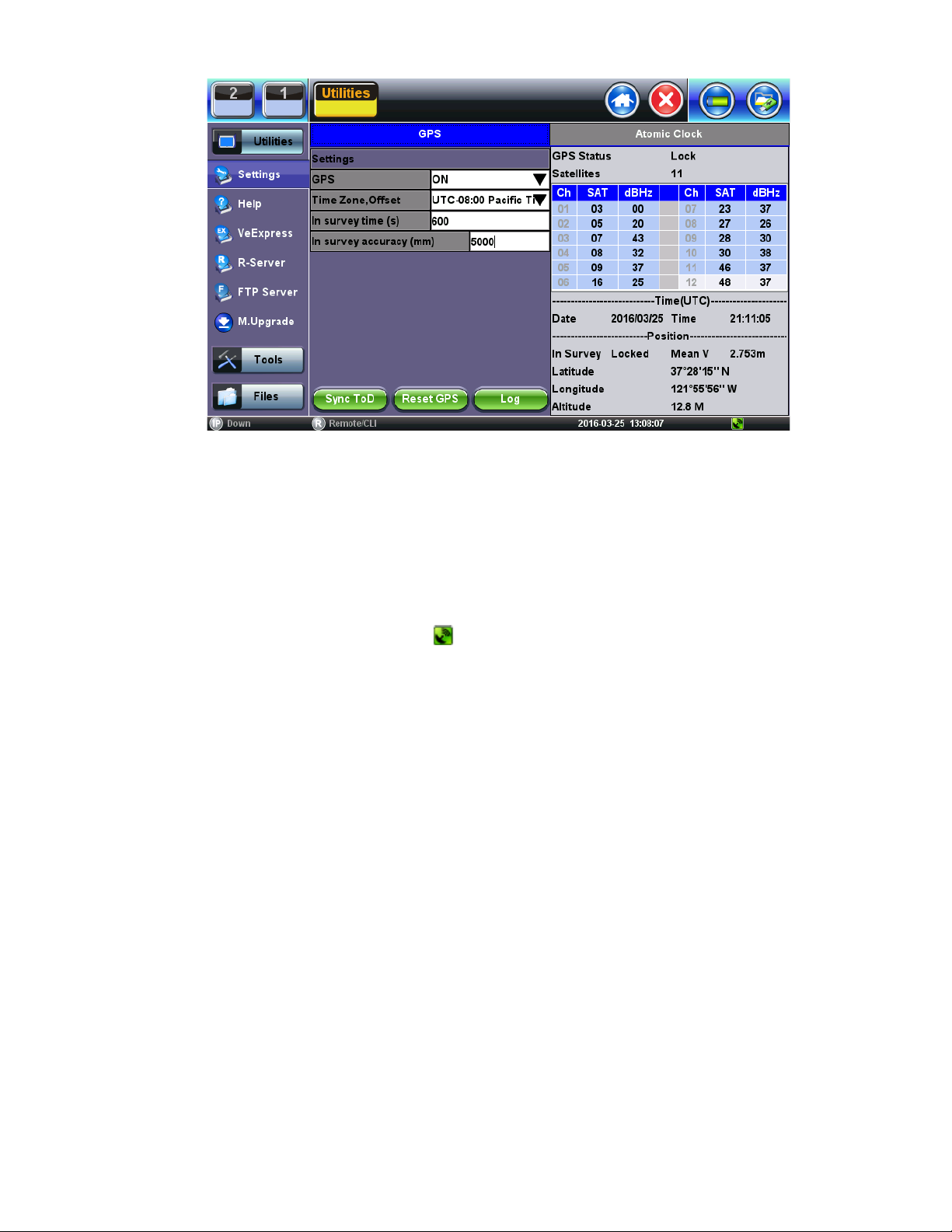
GNSS Receiver On
TX300s_Platform_Manual_RevB00
Page 92 of 104
1. Turn the GNSS Receiver = ON.
2. Set the Satellite System = GPS
3. Set In-survey time (s) = 600, which is the time window used by the GNSS Receiver to assess stable location, using the
specified accuracy (below). Having an accurate tri-dimensional location is required to calculate accurate time.
4. Set In-survey accuracy (m) = 5, which is a target of <5m for the Mean V accuracy reading. Smaller values tighten the
location accuracy requirements, but the site survey process may take longer. It is possible to get better than 1.5m location
accuracy when using professionally-installed roof-top antennas.
5. Enter any antenna cable delay that needs to be compensated for (velocity of propagation is cable dependent, their values are
around 5ns/m or 1.2ns/ft). Enter 20ns if using the 5m portable antenna.
6. Select the Time Zone Offset (it is used to calculate the local time of day).
7. Wait for GPS Status on top to show Lock and for the
icon at the bottom of the screen to turn green. It indicates that it is
successfully tracking enough GPS and GLONASS satellites.
8. Wait for about 15 to 30 minutes for the Mean V value to be below 5.00m and until the In Survey status also shows Locked.
This indicates that the GPS position has reached the required accuracy (site survey finished) and that it has switched into
Timing Mode.
9. At this point, the GPS Module should be providing accurate Time and Timing (1PPS).
10. Tap the Sync ToD button to synchronize the test set’s (system) real-time clock.
Atomic Clock Settings and Operation
This section explains the different disciplining parameters for the optional chip-scale Atomic Clock and provides the settings required
to quickly verify its proper operation. For application-oriented configurations, please refer to the suggested configurations table at the
end of this document.
Free Running Stage (Frequency only)
By default, the built-in Atomic Clock oscillator starts in free-running mode, providing a calibrated Atomic 10MHz frequency reference.
(Its exact frequency could vary over time due to ageing, temperature, storage and other factors.) It also produces an arbitrary (nontraceable) 1PPS timing signal that is not aligned to the standard UTC second. Disciplining must be used in order to make the
necessary frequency and timing corrections.
Oscillator Disciplining Process (Frequency & Phase)
The disciplining process acts as a continuous “soft calibration” that corrects any frequency deviation in the oscillator and aligns the
timing pulse (1PPS) to the standard UTC second. The chip-scale atomic oscillator can be disciplined by:
1. The built-in precision GNSS Receiver (GNSS 1PPS).
2. An external traceable 1PPS signal from a primary reference time clock (PRTC) or time standard (Cs or Rb).
Page 93
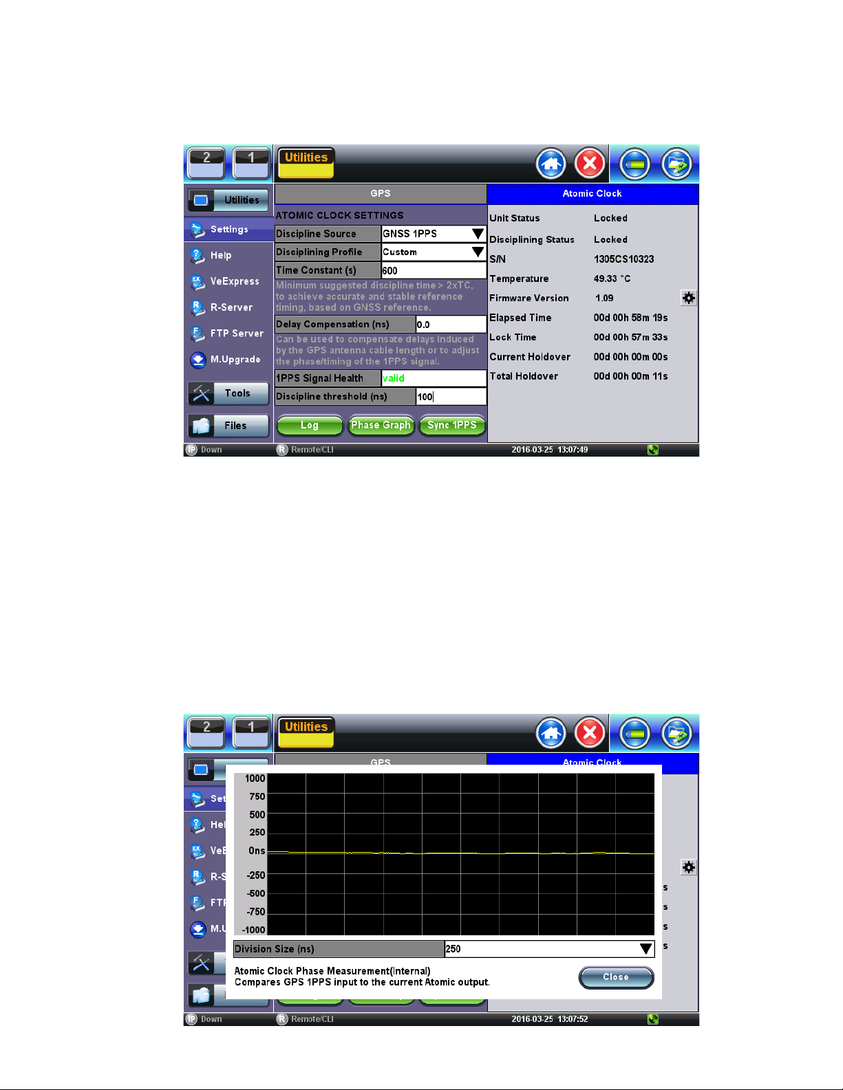
Clock Disciplining - Using the built-in GNSS 1PPS
TX300s_Platform_Manual_RevB00
Page 93 of 104
1. With the GNSS module already locked, go to >Utilities >Settings >More >High Precision Clock >Atomic Clock.
2. Set Discipline Source = GNSS 1PPS, to use the traceable (UTC aligned) 1PPS timing signal from the GNSS receiver.
Discipline Source
3. Verify that 1PPS Signal Health = Valid, to confirm that the one-pulse-per-second signal is being detected.
4. Set Discipline Profile = Custom.
5. Set Time Constant (s) = 60 (this small window is only used to expedite the initial phase alignment process).
6. Set Discipline Threshold (ns) = 100 (a more stringent 50ns could also be tried if applicable. Use the Phase Graph to
determine the stability range).
7. Verify that Disciplining Status = Acquiring. This indicates that the disciplining process is in progress.
8. Tap on the Phase Graph to monitor the relative phase error, until it becomes a horizontal line close to 0ns. The time required
for this may vary (it should take less than 15 minutes)
9. Close the Phase Graph and set the Time Constant (s) = 900. You can also experiment with larger time constants (e.g.
1800s, 3600s, 5400s). The larger the setting the more stringent the disciplining process becomes and the longer it takes to
achieve disciplining lock. To declare lock, the Atomic Clock verifies that the relative phase stays within the defined
Disciplining Threshold for about 2x Time Constant (to confirm its stability). You can use the Phase Graph to monitor the
actual phase variations on your current GNSS environment for the past 600s.
Discipline Source Phase Measurement
10. Open the Phase Graph again to monitor the time error. Once it stabilizes again around 0ns, wait for about 60 minutes. The
line should stay flat and very close to 0ns. If not stable, please check the GPS satellites and antenna installation.
Page 94
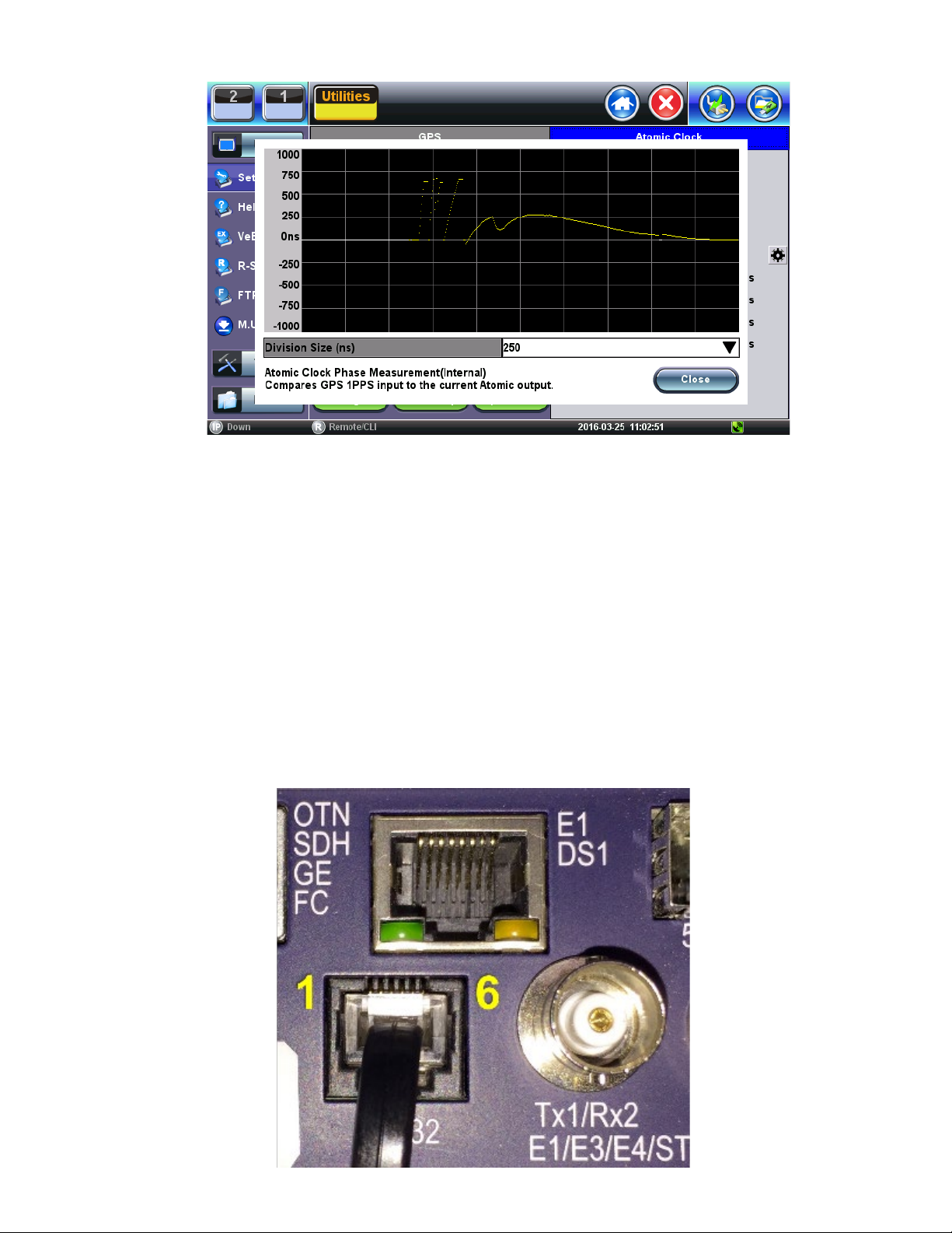
Discipline Source Phase Measurement
TX300s_Platform_Manual_RevB00
Page 94 of 104
11. Close the Phase Graph and verify that the Disciplining Status gets into Locked mode.
At this point the test set’s internal “Atomic 10MHz” frequency and “Atomic 1PPS” timing reference signals can be considered
accurate and stable.
The Phase Graph (above) can be used to monitor the short-term stability of the raw GPS clock, which can be used to determine the
Discipline Threshold for a particular site or scenario. Zoom in to the 50ns grid and estimate how dispersed the 1PPS samples are (in
ns), then use a larger value as a threshold. A vertical variation of <30ns is OK.
Clock Disciplining - Using External 1PPS from a PRTC (Cs or Rb)
The TX300s can also be disciplined, faster and more accurately, using a 1PPS reference signal from a traceable time standard
(PRTC), which can be connected to the test set’s ToD port (RS232).
An RJ11-to-BNC cable is required (RJ11 pin 2 to the BNC’s center pin and RJ11 pin 4 to BNC shield/GND). Keep in mind that the
same RJ11 form factor comes in 4 and 6-pin versions and this document refers to the 6-pin version.
RJ11 to BNC
Page 95

1. Go to >Utilities >Settings >More >High Precision Clock >Atomic Clock.
TX300s_Platform_Manual_RevB00
Page 95 of 104
2. Set Discipline Source = Ext. 1PPS (RJ11).
3. Verify that 1PPS Signal Health = Valid.
4. Set Discipline Profile = Custom.
5. Set Time Constant (s) = 600.
6. Set Discipline Threshold (ns) = 20.
7. Verify that Disciplining Status = Acquiring.
8. Tap on the Phase Graph to monitor the relative phase error, until it becomes a horizontal line at about 0ns.
9. Close the Phase Graph and wait until the Disciplining Status = Locked.
At this point the test set’s internal “Atomic 10MHz” frequency and “Atomic 1PPS” timing reference signals can be considered highly
accurate and stable.
Page 96
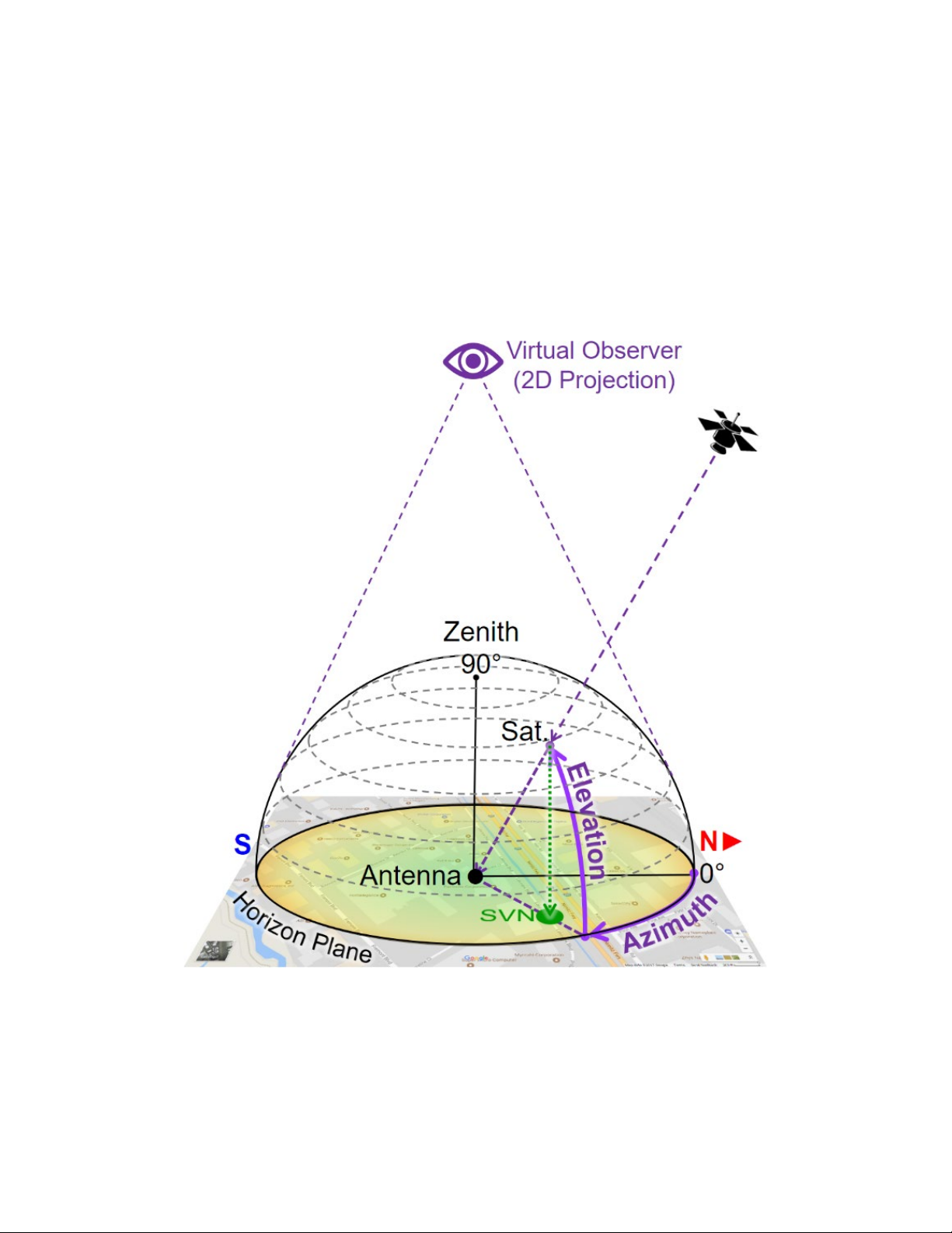
Verifying the Antenna Field of View
TX300s_Platform_Manual_RevB00
Page 96 of 104
Not many of us would be tempted to get on the roof or climb to the top of a tower to perform a 360° visual inspection to identify any
potential satellite signal obstructions. But even if you do, you won’t be able to “see” interference, multi-path or other RF effects.
As all “visible” GNSS satellites move around their orbits, the directional vectors pointing at them form a dome above the antenna.
Their received signal qualities change over time, depending on their elevation angles, obstructions, reflections and other factors.
To track this, you need a tool that records the C/No of every satellite as they pass by the antenna’s aperture (field of view), to create
a flat (2D) projection of a 360° color-coded dome-shaped “heat” map representing the field of view of the antenna and the signal
quality from every direction. These azimuthal graphs allow you to identify areas (directions) with degraded signal quality.
Virtual Observer
Building such maps usually takes >24 hours, to allow each satellite to complete one cycle over the antenna (not to be confused with
their ~12-hour orbital cycles).
Page 97
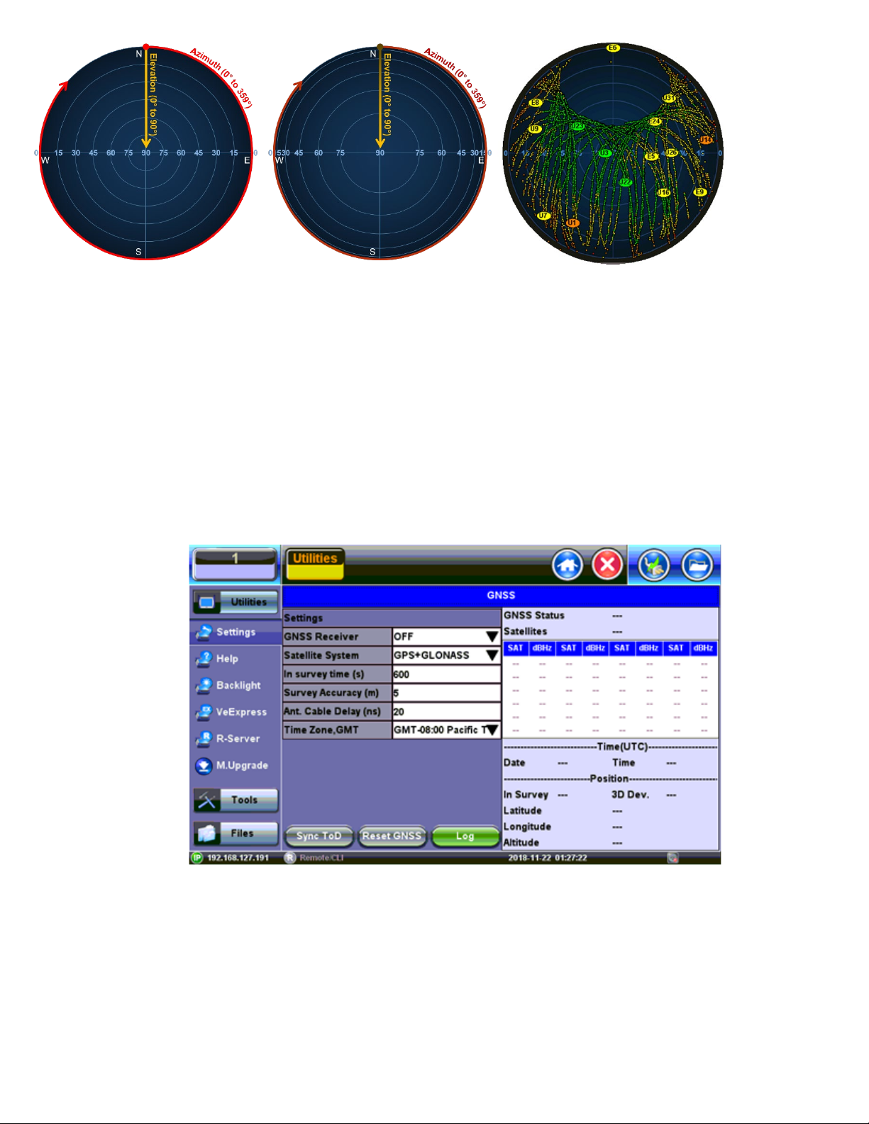
Examples of 2D Linear and Cosine projection (polar) grids, as well as actual satellite trails recorded
TX300s_Platform_Manual_RevB00
Page 97 of 104
This type of tool can also be used to evaluate and bench-mark different antennas in real life and under the same conditions.
The areas in yellow indicate the directions where the degraded satellite signals are, such as RF “shadows” cast by trees and
buildings. They can also indicate interference. As the signal quality degrade even more they turn orange and red. The example
below shows the correlation between the sky view map and a map of the area around the antenna.
7.5.8 GNSS Sky View
1. Go to >Utilities >Settings >More >High Precision Clock.
2. Turn the GNSS Receiver = OFF and close the screen.
GNSS Receiver Off
3. Go to >Tools>Advanced>More>GNSS.
4. Select the Time Zone from the Time Zone Offset: drop-down list box.
5. Enter a Test Name from the File Name: drop-down list box.
6. Select the Duration of the test from the Duration: drop-down list box.
Page 98
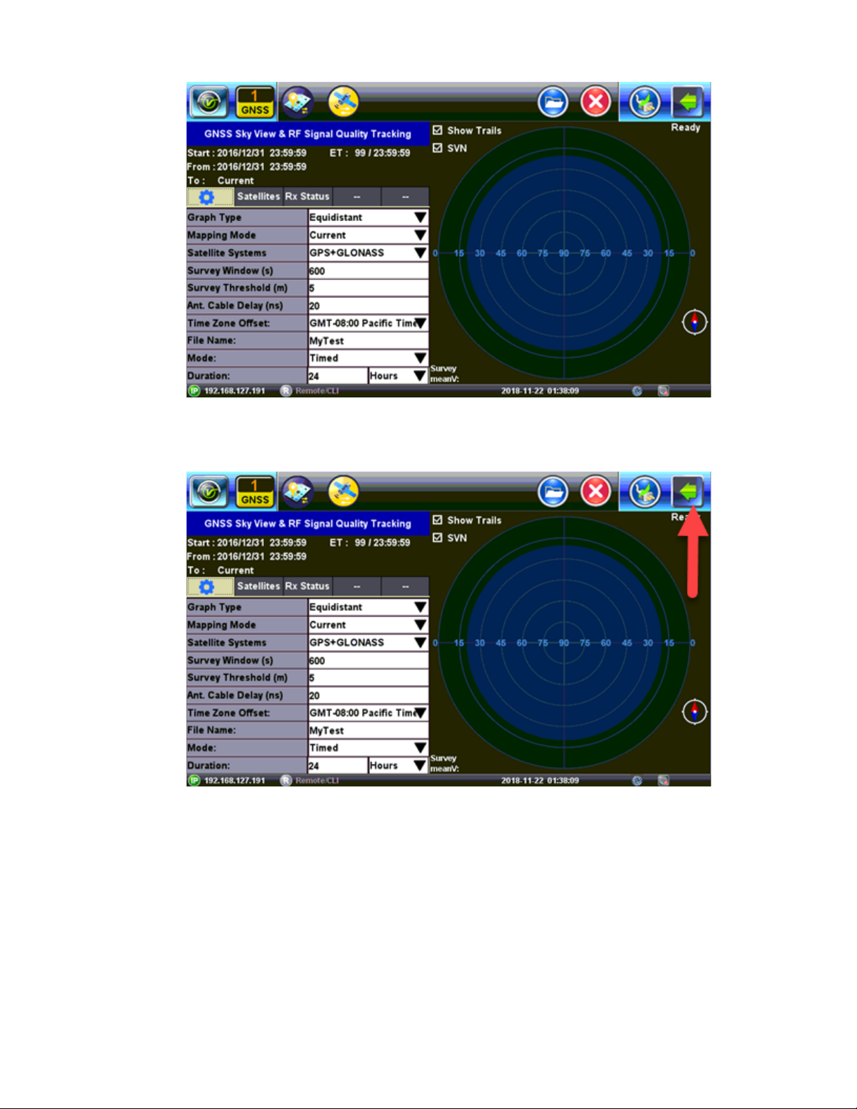
7. Tap on the Arrow to open the menu and tap on Start.
TX300s_Platform_Manual_RevB00
Page 98 of 104
GNSS Setup
GNSS Start Menu
Page 99
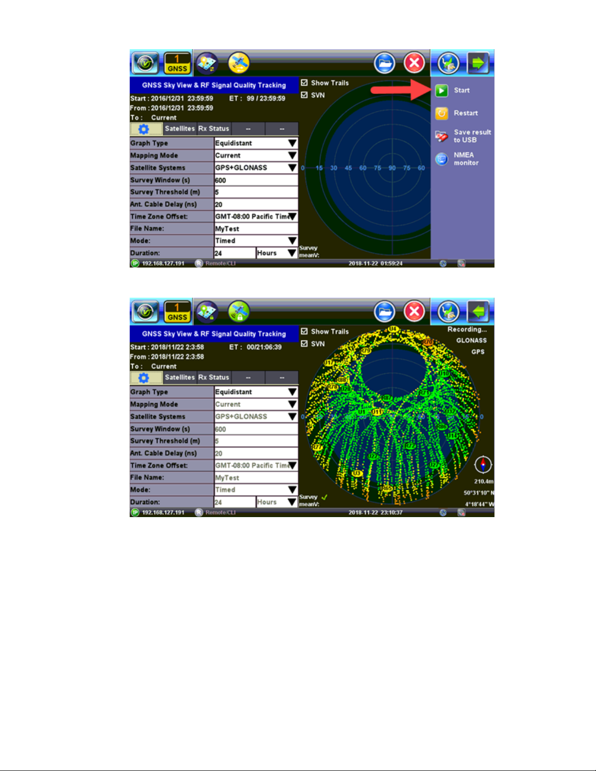
GNSS Start
TX300s_Platform_Manual_RevB00
Page 99 of 104
GNSS Results
1. To save
Results to USB tap on the Arrow and then tap on Save Results To USB.
Page 100
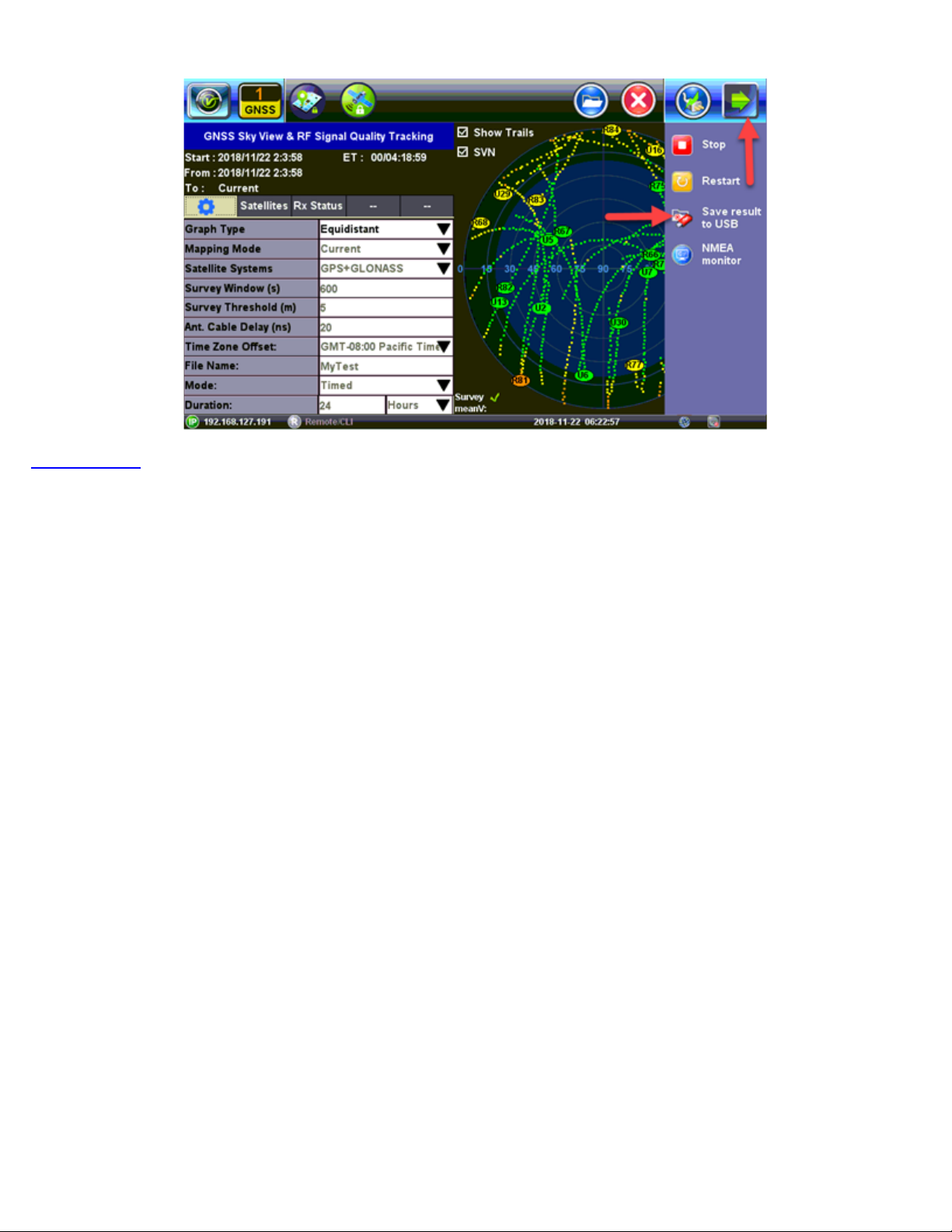
GNSS Save Results
Go back to TOC
TX300s_Platform_Manual_RevB00
Page 100 of 104
 Loading...