

VeEX FX86 User Manual
FX86 CWDM Quad Laser Source User Manual Page 1 of 17

Contents
1.0 About This User Manual ........................................................................................... 3
2.0 Safety Information ..................................................................................................... 4
3.0 Product Introduction ................................................................................................. 5
3.1 FX86 Overview ...................................................................................................................... 5
3.2 Definitions ............................................................................................................................. 6
4.0 Basic Operation ......................................................................................................... 7
4.1 FX86 Front Panel Layout ..................................................................................................... 7
4.1.1 LED Indicators .........................................................................................................................................7
4.1.2 Rubber Keypad ........................................................................................................................................8
4.2 Test Ports .............................................................................................................................. 8
4.2.1 Optical Ports ............................................................................................................................................8
4.2.2 Service Port .............................................................................................................................................8
5.0 Getting Started .......................................................................................................... 9
5.1 Battery ................................................................................................................................... 9
5.1.1 Battery Replacement...............................................................................................................................9
5.2 Instrument Settings ............................................................................................................ 10
5.3 Resetting your FX86 ........................................................................................................... 10
6.0 Fiber Measurements ............................................................................................... 11
6.1 Optical Light Source .......................................................................................................... 11
7.0 Warranty and Software ........................................................................................... 13
8.0 Product Specifications ........................................................................................... 15
9.0 Certifications and Declarations .............................................................................. 16
10.0 About VeEX .............................................................................................................. 17
FX86 CWDM Quad Laser Source User Manual Page 2 of 17

1.0 About This User Manual
This user manual is suitable for novice, intermediate, and experienced users and is intended to
help you successfully use the features and capabilities of the FX86 CWDM Quad Laser
Source. It is assumed that the user has basic computer experience and skills, and is familiar
with optical fiber, telecommunication concepts, terminology, and safety.
Every effort was made to ensure that the information contained in this user manual is accurate.
Information is subject to change without notice and we accept no responsibility for any errors or
omissions. In case of discrepancy, the web version takes precedence over any printed literature.
The content in this manual may vary from the software version installed in the unit.
© Copyright 2019 VeEX, Inc. All rights reserved.
VeEX, VePAL, Sunrise Telecom, Agizer, Optixsoft, Sunlite, Sunset, RXT, MTT, OPX, Fiberizer,
FX, TX and OPX, are trademarks of VeEX, Inc. and/or its affiliates in the USA and certain other
countries. All trademarks or registered trademarks are the property of their respective
companies. No part of this document may be reproduced or transmitted electronically or
otherwise without written permission from VeEX, Inc.
This device uses software either developed by VeEX, Inc. or licensed by VeEX, Inc. from third
parties. The software is confidential and proprietary of VeEX, Inc. The software is protected by
copyright and contains trade secrets of VeEX, Inc. or VeEX's licensors. The purchaser of this
device agrees that it has received a license solely to use the software as embedded in the
device, and the purchaser is prohibited from copying, reverse engineering, decompiling, or
disassembling the software.
For more technical resources, visit the VeEX, Inc. web site at www.veexinc.com.
If you need assistance or have questions related to the use of this product, call or e-mail our
customer care department for customer support. Before contacting our customer care
department, you must have your product serial number and software version ready. Please
provide this number when contacting VeEX customer service.
Customer Care:
Phone: + 1 510 651 0500
E-mail: customercare@veexinc.com
Website: www.veexinc.com
FX86 CWDM Quad Laser Source User Manual Page 3 of 17
2.0 Safety Information
Safety precautions should be observed during all phases of operation of this instrument. The
instrument has been designed to ensure safe operation however please observe all safety
markings and instructions. Do not operate the instrument in the presence of flammable gases
or fumes or any other combustible environment. VeEX Inc. assumes no liability for the
customer's failure to comply with safety precautions and requirements.
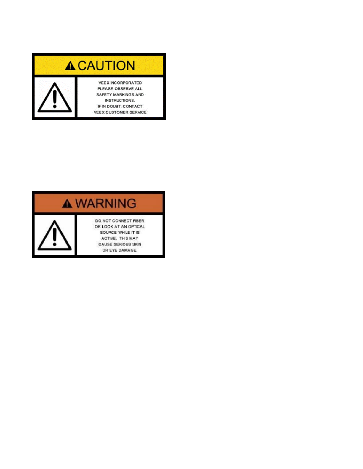
Optical Connectors
The test platform displays a laser warning icon when the laser source is active to alert the user
about a potentially dangerous situation. Make sure that optical sources are inactive before
connecting fiber to the test set to avoid skin or eye damage, or damage to the unit. It is
recommended to:
• Deactivate the laser before connecting or disconnecting optical cables or patchcords.
• Never look directly into an optical patchcord or an optical interface (e.g. CFP, CFP2, CFP4,
QSFP+, SFP+, SFP, OTDR, LS, VFL) while the laser is enabled. Even though optical
transceivers are typically fitted with Class 1 lasers, which are considered eye safe, optical
radiation for an extended period can cause irreparable damage to the eyes.
• Never use a fiber microscope to check the optical connectors when the laser source is
active.
Electrical Connectors
Telephone lines may carry dangerous voltages. Always connect the electrical test ports to
known test interfaces which carry low level signals.
FX86 CWDM Quad Laser Source User Manual Page 4 of 17
3.0 Product Introduction
The FX86 CWDM Quad Laser Source is a handheld optical testing device for providing
calibrated laser radiation, to be used together with an optical power meter. The accompanying
power meter must be calibrated to one of the FX86 laser wavelengths. For the power meter
operations, please see its manual.
3.1 FX86 Overview
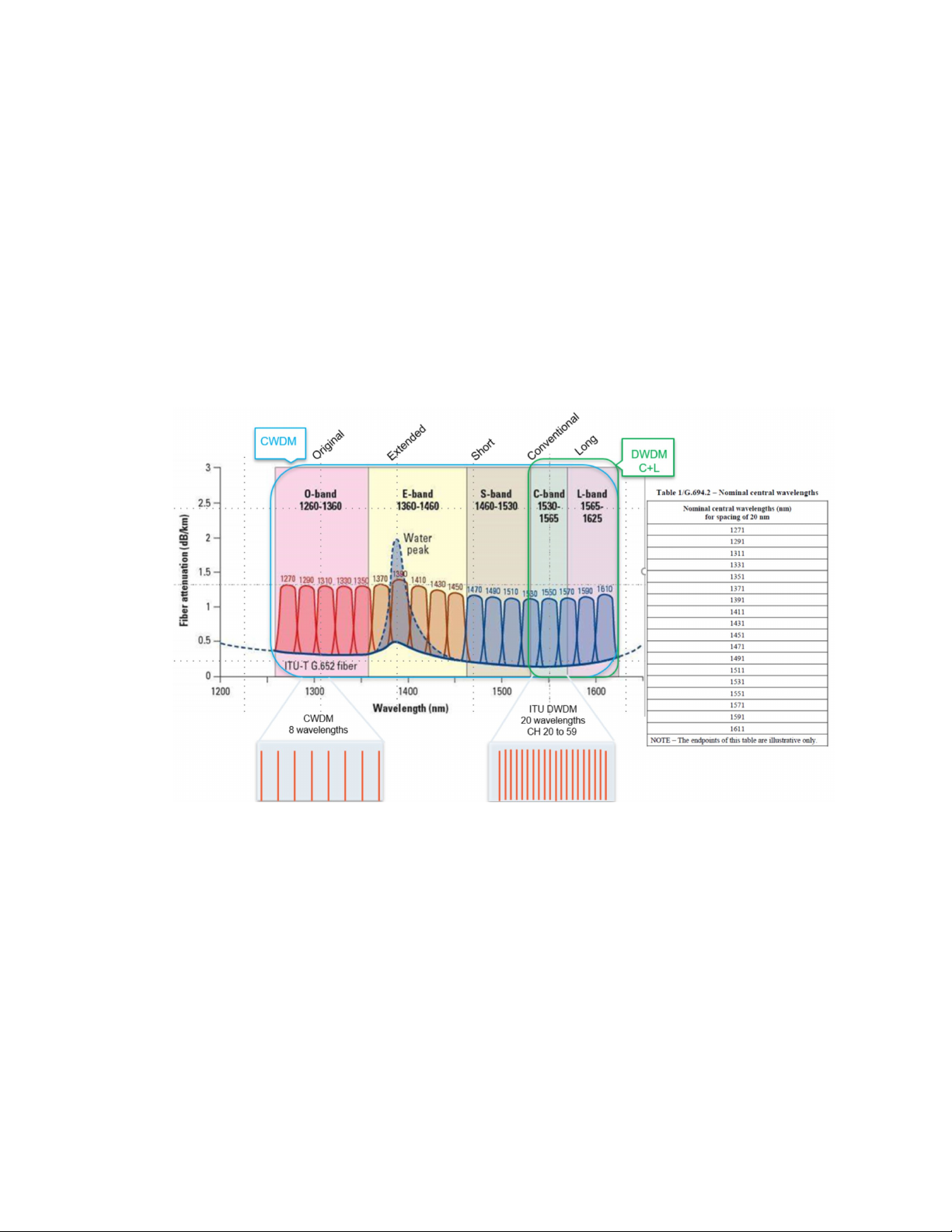
CWDM – Course Wavelength Division Multiplexing is a WDM technology characterized by
wide, 20 nm channel spacing and grid wavelengths with 1271 nm to 1611 (16 active channels)
and is typically used for shorter distances as found in city and access networks.
CWDM Spectrum Graph
The FX86 CWDM Quad Laser Source is specially engineered to test CWDM systems. A single
device can support up to 4 fixed wavelengths for OLS fiber optic network testing and
measurement, defined by the customer upon ordering. The wavelengths can be any 4 values
in the 1270 – 1610 nm range incremented by 20 nm, in any combination.
To make the fiber identification in a rack more convenient, the laser signal from FX86 with a
calibrated wavelength (see the CDWM set of calibrated wavelengths above) is also modulated
with the following frequencies:
• CW (Continuous Wave)
• 270 Hz
• 330 Hz
• 1000 Hz
• 2000 Hz
FX86 CWDM Quad Laser Source User Manual Page 5 of 17

3.2 Definitions
• APC (Angled Physical Contact): better than -65 dB return loss
Patchcords can be made with singlemode or multimode fiber.
end face is always flat.
panels or patch panels
accommodate different male Optical Connectors.
Optical Interface: PC, UPC, APC (designates the connector end face polish type):
• PC (regular Physical Contact): better than -45 dB return loss
• UPC (Ultra Physical Contact): better than -55 dB return loss
Optical Patchcord: A fiber (typically tight-buffered) terminated with an Optical
Connector on each end (see below). Patchcords can be
configured in simplex, duplex, or ribbon cable configuration.
Optical Connector: A patchcord is terminated with a MALE type connector. There are
a wide variety of optical connectors, such as FC, SC, LC, MU, etc.
For singlemode fiber, the end face can have either ‘flat’ or ‘angled’
Optical Polish (for example, FC/UPC or FC/APC). Multimode fiber
Fixed Optical Adapter:
(mid-coupler or
bulkhead)
Variable Optical
Adapter:
The adapter is used to connect two male Optical Connectors
together (Example: FC-FC, FC-SC, FC-LC).
On a test set with universal interface option, one side of the
coupler may be changed by user using universal/variable adapters
(see Variable Optical Adapter). However, the connectors have to
be of the same Optical Polish (for example FC/UPC or FC/APC).
Optical Adapters are located on instrument test ports (OTDR,
Power Meter, Light Source, OSA, etc.), network equipment front
Unlike with the Fixed Optical Adapter, one or both end female
connectors of a Variable Optical Adapter can be changed to
FX86 CWDM Quad Laser Source User Manual Page 6 of 17
 Loading...