

Page 1
FX180X Channel Checker e-Manual, D07-00-128P-RevA00 Page 1 of 19
FX180X Channel Checker e-Manual, D07-00-128P-RevA00 Page 1 of 19
FX180X
Channel Checker
Page 2

FX180X Channel Checker e-Manual, D07-00-128P-RevA00 Page 2 of 19
Table of Contents
1.0 ABOUT THIS USER MANUAL ................................................................................... 3
2.0 PRODUCT INTRODUCTION ...................................................................................... 4
2.1 FX180X HIGHLIGHTS ............................................................................................................... 4
2.2 KEY FEATURES ........................................................................................................................ 4
2.3 FX180 PACKAGE CONTENTS .................................................................................................... 5
3.0 SAFETY INFORMATION ............................................................................................ 6
4.0 BASIC OPERATION ................................................................................................... 7
4.1 FX180X FRONT PANEL LAYOUT ............................................................................................... 7
4.1.1 LED Indicators .........................................................................................................................................7
4.1.2 Rubber Keypad ........................................................................................................................................8
4.2 GETTING STARTED WITH THE FX180 ......................................................................................... 9
4.2.1 View/Hide side menu panels ..................................................................................................................9
4.2.2 A/B Markers .......................................................................................................................................... 10
4.2.3 Active Channel Threshold ................................................................................................................... 10
4.2.4 Pass/Fail Threshold ............................................................................................................................. 10
4.2.5 Setting up FX180X WiFi/Bluetooth ..................................................................................................... 11
4.3 CUSTOMIZING THE TEST UNIT ................................................................................................. 11
5.0 WORKING WITH THE CHANNEL CHECKER ......................................................... 13
5.1 REPEAT SWEEP ..................................................................................................................... 13
5.2 VIEW MODE ........................................................................................................................... 13
5.2.1 Bar Graph View ..................................................................................................................................... 13
5.2.2 Table View ............................................................................................................................................. 14
5.3 SAVING RESULTS ................................................................................................................... 14
6.0 WARRANTY AND SOFTWARE ............................................................................... 15
7.0 PRODUCT SPECIFICATIONS .................................................................................. 17
8.0 CERTIFICATIONS AND DECLARATIONS .............................................................. 18
9.0 ABOUT VEEX ........................................................................................................... 19
Page 3

FX180X Channel Checker e-Manual, D07-00-128P-RevA00 Page 3 of 19
1.0 About This User Manual
This user manual is suitable for novice, intermediate, and experienced users and is intended to
help you successfully use the features and capabilities of the FX180X Optical Channel
Checker Meter. It is assumed that the user has basic computer skills and is familiar with optical
fiber, telecommunication concepts, terminology, and safety.
Every effort was made to ensure that the information contained in this user manual is accurate.
Information is subject to change without notice and we accept no responsibility for any errors
or omissions. In case of discrepancy, the web version takes precedence over any printed
literature. The content in this manual may vary from the software version installed in the unit.
© Copyright 2018 VeEX, Inc. All rights reserved.
VeEX, VePAL, Sunrise Telecom, Agizer, Optixsoft, Sunlite, Sunset, RXT, MTT, Fiberizer, FX,
TX and OPX, are trademarks of VeEX, Inc. and/or its affiliates in the USA and certain other
countries. All trademarks or registered trademarks are the property of their respective
companies. No part of this document may be reproduced or transmitted electronically or
otherwise without written permission from VeEX, Inc.
This device uses software either developed by VeEX, Inc. or licensed by VeEX, Inc. from third
parties. The software is confidential and proprietary of VeEX, Inc. The software is protected by
copyright and contains trade secrets of VeEX, Inc. or VeEX's licensors. The purchaser of this
device agrees that it has received a license solely to use the software as embedded in the
device, and the purchaser is prohibited from copying, reverse engineering, decompiling, or
disassembling the software.
For more technical resources, visit the VeEX, Inc. web site at www.veexinc.com.
If you need assistance or have questions related to the use of this product, call or e-mail our
customer care department for customer support. Before contacting our customer care
department, you must have your product serial number and software version ready. Please
provide this number when contacting VeEX customer service.
Customer Care:
Phone: + 1 510 651 0500
E-mail: [email protected]
Website: www.veexinc.com
Page 4

FX180X Channel Checker e-Manual, D07-00-128P-RevA00 Page 4 of 19
2.0 Product Introduction
The FX180 Channel Checker is a handheld measurement tool for xWDM fiber networks. The
C-band DWDM model can measure up to 96 ITU-T channels in a single test. It measures
individual channel power and wavelength or frequency, as well as Total Span power between
2 markers. An optional FiberScope is available to assist with inspecting connector endfaces.
2.1 FX180X Highlights
• Compact, hand-held field test unit with color touch-screen for easy viewing, fast navigation,
and easy operation
• Internal 8G data storage
• Micro-USB OTG interface for flash drives, fiber inspection probe connection and test data
transfer
• ReVeal FX300 for remote control, and file management and transfer
• Rechargeable Lithium Polymer battery with >9 hours continuous operation, which features
a capacity indicator, low voltage alarm, and Auto-off function
• Optional built-in WiFi and Bluetooth support to perform software upgrades and pair with
mobile devices, respectively
• OTG to Ethernet support option
2.2 Key Features
• • Measure 50/100 /200GHz DWDM ITU-T Channels 14-62
• • Ideal for Remote PHY Deployments
• • Bar Graph or Table View mode
• • Active Channel threshold
• • Pass/Fail thresholds
• • A/B channel markers
• • Built-in wavelength reference
• • Fast < 5 seconds to measure up to 96 channels @ 50 GHz
• • Continuous Testing
• • Generate and save test results in HTML file format
• • High wavelength accuracy: ± 50 pm
• • Dynamic Measurement range: ≥ 65 dB
• • Low Polarization Dependent Loss (PDL): < 0.3 dB
• • DWDM Optical Rejection Ratio: > 40 dB @ 200 GHz
Page 5

FX180X Channel Checker e-Manual, D07-00-128P-RevA00 Page 5 of 19
• • Optional universal interface with interchangeable adaptors
• • DWDM C-Band channel measurements per ITU-T G.694.1 grid
2.3 FX180 Package Contents
• FX180X test unit
• AC/DC adaptor
• Input: 100-240 VAC (50/60 Hz)
• Output: 16VDC
• Li-Ion battery (8400 mAH battery)
• USB memory stick (2 Gbyte) or CD-ROM containing:
• FX180X Channel Checker Users’ Manual (pdf)
• Software Upgrade Instructions
Page 6
FX180X Channel Checker e-Manual, D07-00-128P-RevA00 Page 6 of 19
3.0 Safety Information
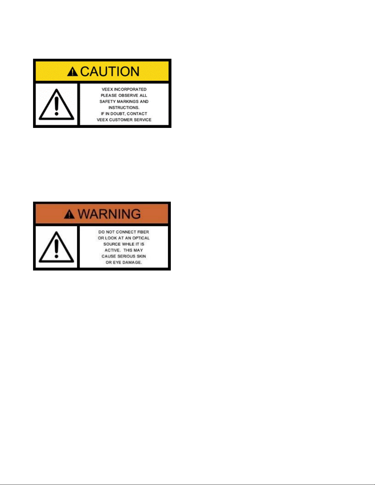
Safety precautions should be observed during all phases of operation of this instrument. The
instrument has been designed to ensure safe operation however please observe all safety
markings and instructions. Do not operate the instrument in the presence of flammable gases
or fumes or any other combustible environment. VeEX Inc. assumes no liability for the
customer's failure to comply with safety precautions and requirements.
Optical Connectors
The test platform displays a laser warning icon when the laser source is active to alert the user
about a potentially dangerous situation. Make sure that optical sources are inactive before
connecting fiber to the test set to avoid skin or eye damage. To avoid damage to the unit, it is
recommended to:
• Deactivate the laser before connecting or disconnecting optical cables or patchcords.
• Never look directly into an optical patchcord or an optical interface (e.g. CFP, CFP2, CFP4,
QSFP+, SFP+, SFP, OTDR, LS, VFL) while the laser is enabled. Even though optical
transceivers are typically fitted with Class 1 lasers, which are considered eye safe, optical
radiation for an extended period can cause irreparable damage to the eyes.
• Never use a fiber microscope to check the optical connectors when the laser source is
active.
Electrical Connectors
Telephone lines may carry dangerous voltages. Always connect the electrical test ports to
known test interfaces which carry low level signals.
Page 7
FX180X Channel Checker e-Manual, D07-00-128P-RevA00 Page 7 of 19
4.0 Basic Operation
4.1 FX180X Front Panel Layout
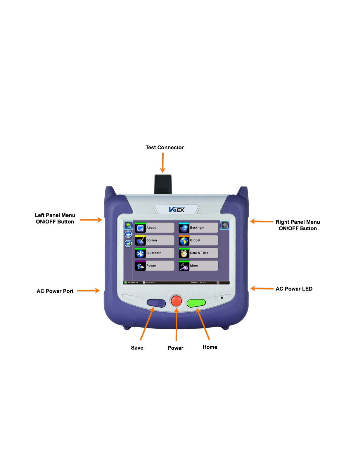
The FX180 Channel Checker Meter is available for DWDM C-band network testing. Other
models may be available in the future.
• DWDM C-Band: 1527 - 1567nm
Display Modes include: Bar Graph and Table Display views.
4.1.1 LED Indicators
Power LED: A single LED indicates the power state of the unit.
• The LED is off when the unit is powered off.
• The LED is green when the unit is powered on.
The LED is orange when the unit is connected to the AC power port and powered off
(charging).
Page 8
FX180X Channel Checker e-Manual, D07-00-128P-RevA00 Page 8 of 19
again to return to normal operation.
• Save + Home: Calibrates touchscreen
4.1.2 Rubber Keypad
• Save: Saves current test results with automatic
naming and time stamping. Also saves the current
screenshot.
• Power: Press for 2 seconds to turn the test set ON
or OFF (prevents accidental ON/OFF).
To force the Power OFF, press for 6 seconds.
• Home: Resets user interface to Main menu. Press
the Home key for 3 seconds to put the test unit in
Sleep Mode. Press the Home key for 3 seconds
• Power + Save: Formats SD card and upgrades
firmware. This clears data and settings on the test
unit.
• Power + Home: Upgrades firmware. This does not
clear data and settings.
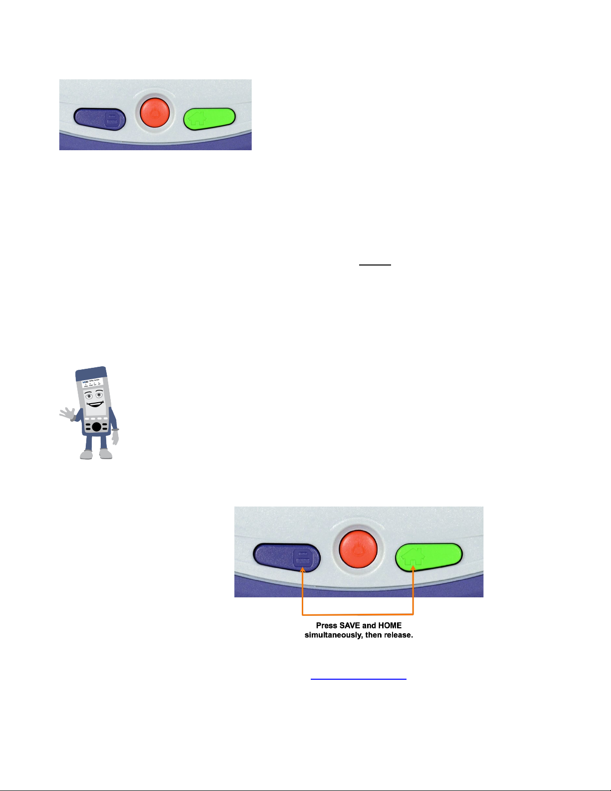
Activating Touchscreen Calibration Mode
To calibrate the touchscreen:
1. Press the SAVE + HOME keys simultaneously, and then
release.
2. To cancel, press any button. To continue the calibration, press
the LEFT SIDE rocker button, then press the SAVE + HOME
keys simultaneously, and then release.
3. Use the Stylus to tap individual calibration targets.
For more detailed instructions, see the V150 Series Common
Functions User Manual at www.veexinc.com.
Page 9
FX180X Channel Checker e-Manual, D07-00-128P-RevA00 Page 9 of 19
4.2 Getting Started with the FX180
4.2.1 View/Hide side menu panels
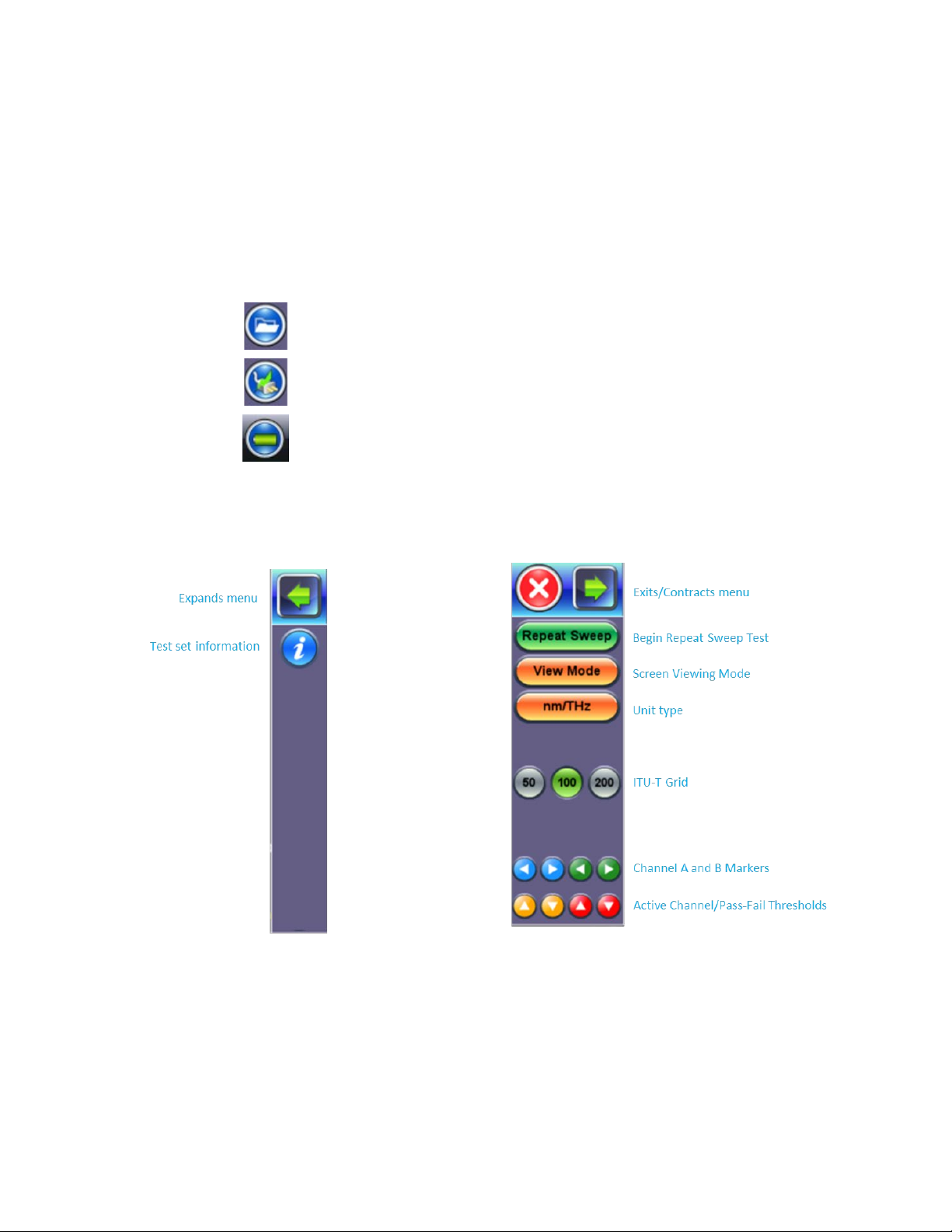
The left and right menu panels contain icons to access key functions of the FX180. These
panels can be minimized to enable a better view of the application screens.
Use the rocker buttons located on the left and right sides of the unit to expand/contract
the left and right menu panels.
Press the LEFT SIDE KEY to access:
File Storage – Tap to see the size and current capacity
of the internal SSD storage.
Power Source Indicator– Indicates when unit is
The RIGHT-SIDE KEY provides access to Spectrum Mode and ITU Test Modes.
powered by external AC power and battery charging
level. Tap to see battery charge status.
Spectrum Mode and ITU Test Modes: Right side Touchscreen Controls
Page 10
FX180X Channel Checker e-Manual, D07-00-128P-RevA00 Page 10 of 19
4.2.2 A/B Markers
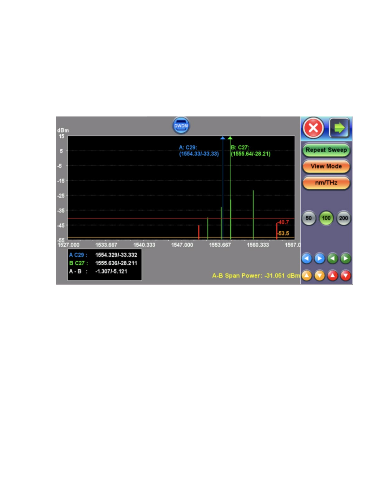
Use the stylus provided with the test set and select A or B markers on the touchscreen to drag
the marker left or right to the point of interest. Alternatively, tap the left/right arrows whose
color matches the marker. You can also tap next to the left or right side of the marker to move
one display pixel. Channel details can be viewed on the touchscreen or the marker detail box.
The span power between the two markers is displayed also.
A/B Markers Control
4.2.3 Active Channel Threshold
Use the stylus provided with the test set to select the gold color horizontal line to move up and
down or tap the gold up/down arrows. You can also tap next just above or below the gold line
to move the threshold level. Any channel below the line will not appear in the results table.
4.2.4 Pass/Fail Threshold
Use the stylus provided with the test set to select the red color horizontal P/F threshold to
move up and down or tap the gold up/down arrows. You can also tap next just above or below
the red line to move the level. Any channel above the red line will be displayed in green.
Channels that fall below the P/F level will appear in red in the graph.
Page 11
FX180X Channel Checker e-Manual, D07-00-128P-RevA00 Page 11 of 19
4.2.5 Setting up FX180X WiFi/Bluetooth
The FX180X unit contains an optional built-in WiFi and Bluetooth interface allowing you to
transfer OSA results and upgrade software on the unit.
For detailed instructions, see the V150 Series Common Functions User Manual at
www.veexinc.com.
4.3 Customizing the Test Unit
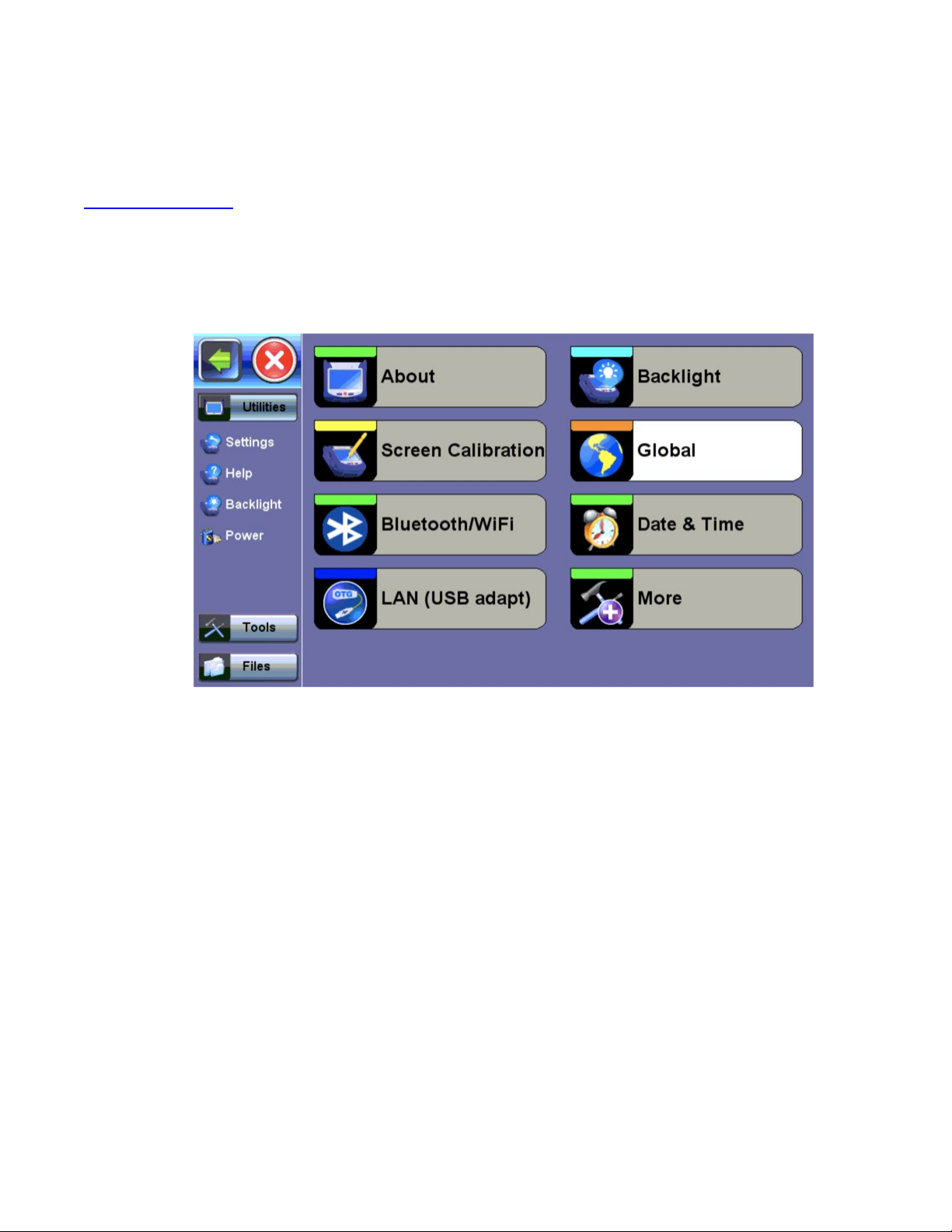
Customize the settings on your device in the Utilities>Settings menu.
FX180X Channel Checker Utilities Settings menu
About: Provides information about the serial number, MAC address, software version, and
software options installed on test set.
Screen Calibration: Calibrates the touch screen.
Bluetooth/WiFi: Define settings for optional built-in Bluetooth and WiFi connectivity.
LAN (USB adapt): Settings for WiFi connectivity to the unit and for the micro-USB Bluetooth
adaptor offering wireless connectivity up to 10 meters (30 feet), so test results can be
transferred without having to use a memory stick or having an Ethernet connection.
Backlight: Define settings when unit is used on battery or AC power, including brightness
settings. The Backlight settings affect battery autonomy and LCD life.
Global: Settings for language, alarm, password, and user interface (International or USA)
Date & Time: Settings for the data and time on the unit. Daylight savings is enabled
automatically.
Remote Access: Settings for the unit’s VNC service. It is not recommended for multi-user or
multi-test environments.
Page 12

FX180X Channel Checker e-Manual, D07-00-128P-RevA00 Page 12 of 19
Power: Provides information about current power source and information about the battery
gauge.
EZ Remote: Settings for connecting to the unit across the Internet or Network Segments
without requiring public IP addresses, port forwarding, or holes in the firewall.
For detailed instructions about customizing the test unit, see the V150 Series Common
Functions User Manual at www.veexinc.com.
Page 13
FX180X Channel Checker e-Manual, D07-00-128P-RevA00 Page 13 of 19
5.0 Working with the Channel Checker
The following model is available: (Refer to the datasheets for exact model availability and
analysis plans at www.veexinc.com .)
• C-band DWDM options: 200 GHz, 100 GHz, 50 GHz ITU Grid DWDM
5.1 Repeat Sweep
The FX180X will measure all channels on the WDM network.
Repeat Sweep: Continues sweep until DWDM measurement is terminated manually by
selecting the Stop button. When in Repeat Sweep test mode, the label will change to Stop.
5.2 View Mode
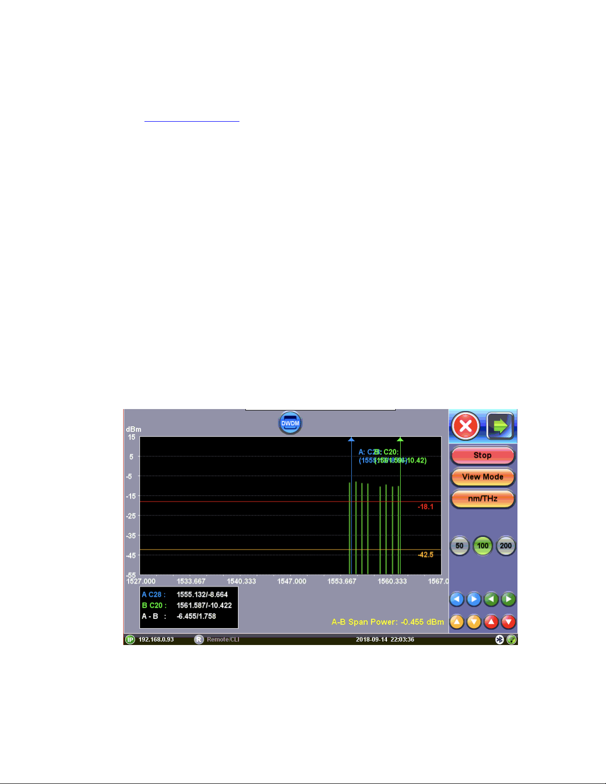
5.2.1 Bar Graph View
Any channel that measures within 24.5% of an ITU-T channel will be displayed in this view. In
the figure below, Channels 20 to 28, except 24, are displayed. This can be due to CH24 having
shifted too far from the nominal ITU-T channel frequency or CH24 has not been brought into
service yet.
ITU Bar Graph view
Page 14
FX180X Channel Checker e-Manual, D07-00-128P-RevA00 Page 14 of 19
5.2.2 Table View
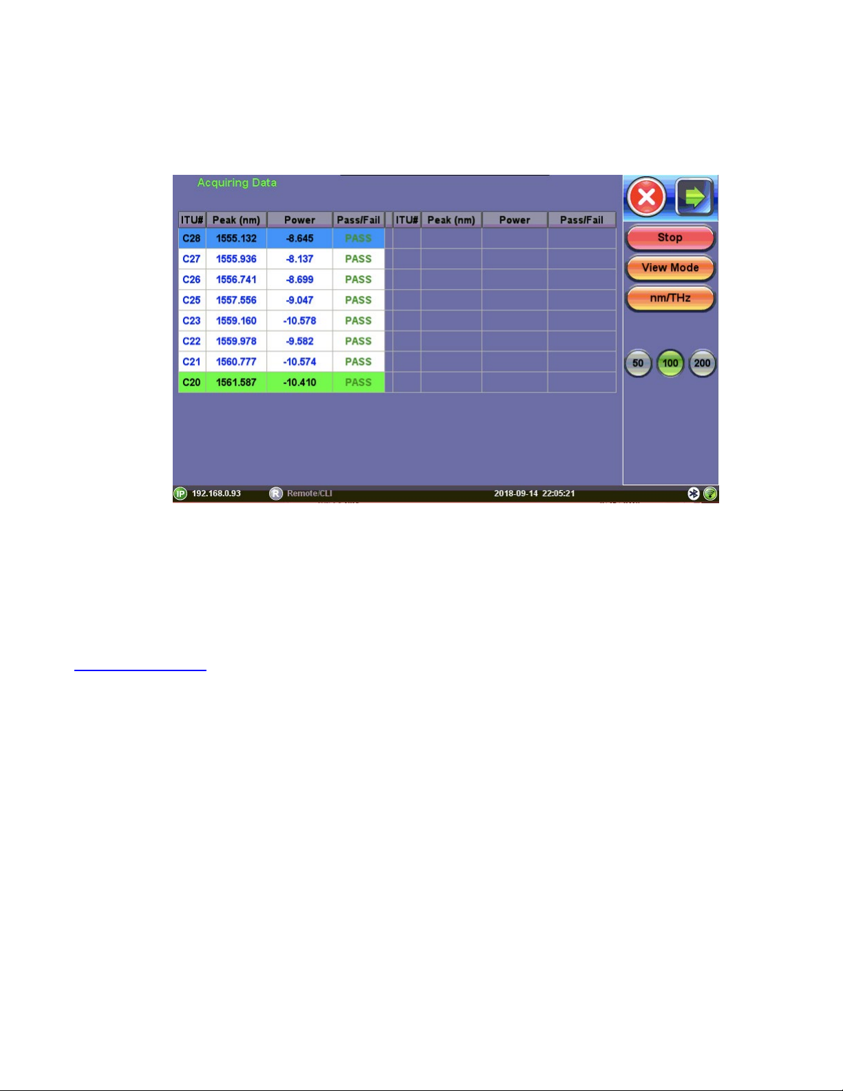
All active ITU-T channels will be displayed in the table. Each channel #, peak frequency or
wavelength, and channel power is displayed.
ITU-T Table view
5.3 Saving Results
Use the Files menu on the home page left panel to access File Management functions. For
detailed instructions, see the V150 Series Common Functions User Manual at
www.veexinc.com.
Page 15

FX180X Channel Checker e-Manual, D07-00-128P-RevA00 Page 15 of 19
6.0 Warranty and Software
Warranty Period: The warranty period for hardware, software and firmware is one (1) year
from the date of shipment to the customer. The warranty period for battery pack, LCD, LCD
touch panel, LCD protective cover, and accessories (including, but not limited to patch cords,
AC adaptor, SFP, USB adaptors, carrying case, carrying pouch) is limited to one (1) year.
Hardware Coverage: VeEX Inc. warrants hardware products against defects in materials and
workmanship. During the warranty period, VeEX Inc. will, at its sole discretion, either
• Repair the products
Replace hardware which prove to be defective
provided that the products that the customer elects to replace are returned to VeEX Inc. by the
customer, along with Proof of Purchase, within thirty (30) days of the request by the customer,
freight prepaid.
Software Coverage: VeEX Inc. warrants software and firmware materials against defects in
materials and workmanship. During the warranty period, VeEX Inc. will, at its sole discretion,
either
• Repair the products
Replace software and/or firmware which prove to be defective
provided that the products that the customer elects to replace are returned to VeEX Inc. by the
customer, along with proof of purchase, within thirty (30) days of the request by the customer,
freight prepaid.
Additionally, during the warranty period, VeEX Inc. will provide, without charge to the
customer, all fixes, patches and enhancements to the purchased software, firmware and
software options. VeEX Inc. does not warrant that all software or firmware defects will be
corrected. New enhancements attached to a software option require the option to be
purchased (at the time of order or the time of upgrade) in order to benefit from such
enhancements.
Limitations: The warranty is only for the benefit of the customer and not for the benefit of any
subsequent purchaser or licensee of any merchandise (hardware, software, firmware and/or
accessories).
Revoking the warranty: VeEX Inc. does not guarantee or warrant that the operation of the
hardware, software or firmware will be uninterrupted or error-free. The warranty will not apply
in any of the following cases:
• Improper or inadequate maintenance by the customer
• Damage due to software installed by the customer on the unit without prior authorization
(written) from VeEX Inc.
Page 16

FX180X Channel Checker e-Manual, D07-00-128P-RevA00 Page 16 of 19
• Unauthorized alteration or misuse
• Damage occurred from operating the unit outside of the environmental specifications for the
product
• Improper installation by the customer
Page 17

FX180X Channel Checker e-Manual, D07-00-128P-RevA00 Page 17 of 19
7.0 Product Specifications
The most recent product specifications can be found on the VeEX web site at
www.veexinc.com.
Page 18
FX180X Channel Checker e-Manual, D07-00-128P-RevA00 Page 18 of 19
VeEX products, please contact VeEX customer service.
8.0 Certifications and Declarations
What is CE?
The CE marking is a mandatory European marking for
certain product groups to indicate conformity with the
essential health and safety requirements set out in European
Directives. To permit the use of a CE mark on a product,
proof that the item meets the relevant requirements must be
documented.
Use of this logo implies that the unit conforms to
requirements of European Union and European Free Trade
Association (EFTA). EN61010-1
For a copy of the CE Declaration of Conformity relating to
What is RoHS?
RoHS is the acronym for Restriction of Hazardous
Substances. Also known as Directive 2002/95/EC, it
originated in the European Union and restricts the use of
specific hazardous materials found in electrical and electronic
products. All applicable products imported into the EU market
after July 1, 2006 must pass RoHS compliance.
For more information about RoHS as it relates to VeEX Inc,
go to the VeEX web site at www.veexinc.com.
Page 19

FX180X Channel Checker e-Manual, D07-00-128P-RevA00 Page 19 of 19
9.0 About VeEX
VeEX Inc., the Verification EXperts, is an innovative designer and manufacturer of test and
measurement solutions addressing numerous technologies. Global presence through a
worldwide distribution channel provides uncompromised product support.
Visit us online at www.veexinc.com for the latest updates and additional documentation.
VeEX Incorporated
2827 Lakeview Court
Fremont, CA 94538
USA
Phone: +1 510 651 0500
Fax: +1 510 651 0505
Customer Care
Phone: + 1 510 651 0505
Email: [email protected]
 Loading...