

Page 1

TLS-50
Site Prep Manual
Manual No: 577013-608 ● Revision: N
Page 2

Notice
Veeder-Root makes no warranty of any kind with regard to this publication, including, but not limited to, the implied warranties of
merchantability and fitness for a particular purpose.
Veeder-Root shall not be liable for errors contained herein or for incidental or consequential damages in connection with the furnishing,
performance, or use of this publication.
Veeder-Root reserves the right to change system options or features, or the information contained in this publication.
This publication contains proprietary information which is protected by copyright. All rights reserved. No part of this publication may be
photocopied, reproduced, or translated to another language without the prior written consent of Veeder-Root.
DAMAGE CLAIMS / LOST EQUIPMENT
Thoroughly examine all components and units as soon as they are received. If any cartons are damaged or missing, write a complete
and detailed description of the damage or shortage on the face of the freight bill. The carrier's agent must verify the inspection and sign
the description. Refuse only the damaged product, not the entire shipment.
VEEDER-ROOT’S PREFERRED CARRIER
1. Contact VR Customer Service at 800-873-3313 with the specific part numbers and quantities that were missing or received
damaged.
2. Fax signed Bill of Lading (BOL) to VR Customer Service at 800-234-5350.
3. VR will file the claim with the carrier and replace the damaged/missing product at no charge to the customer. Customer Service
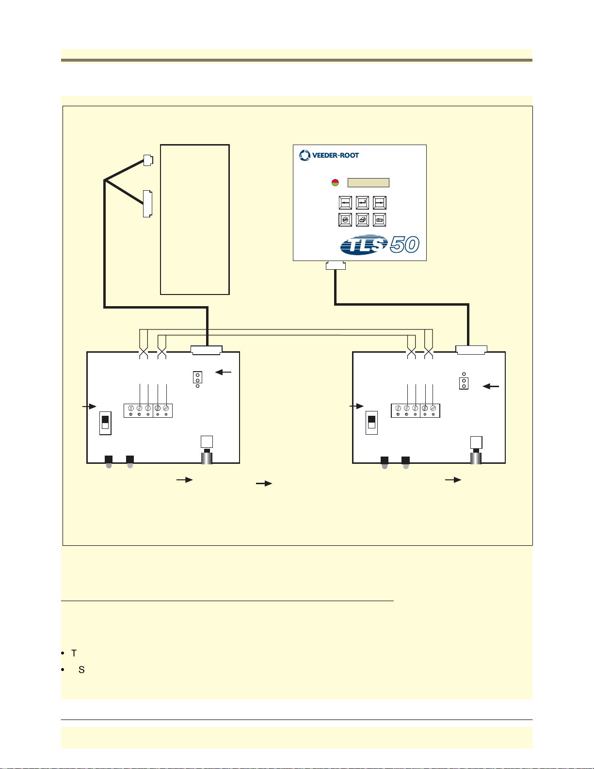
will work with production facility to have the replacement product shipped as soon as possible.
CUSTOMER’S PREFERRED CARRIER
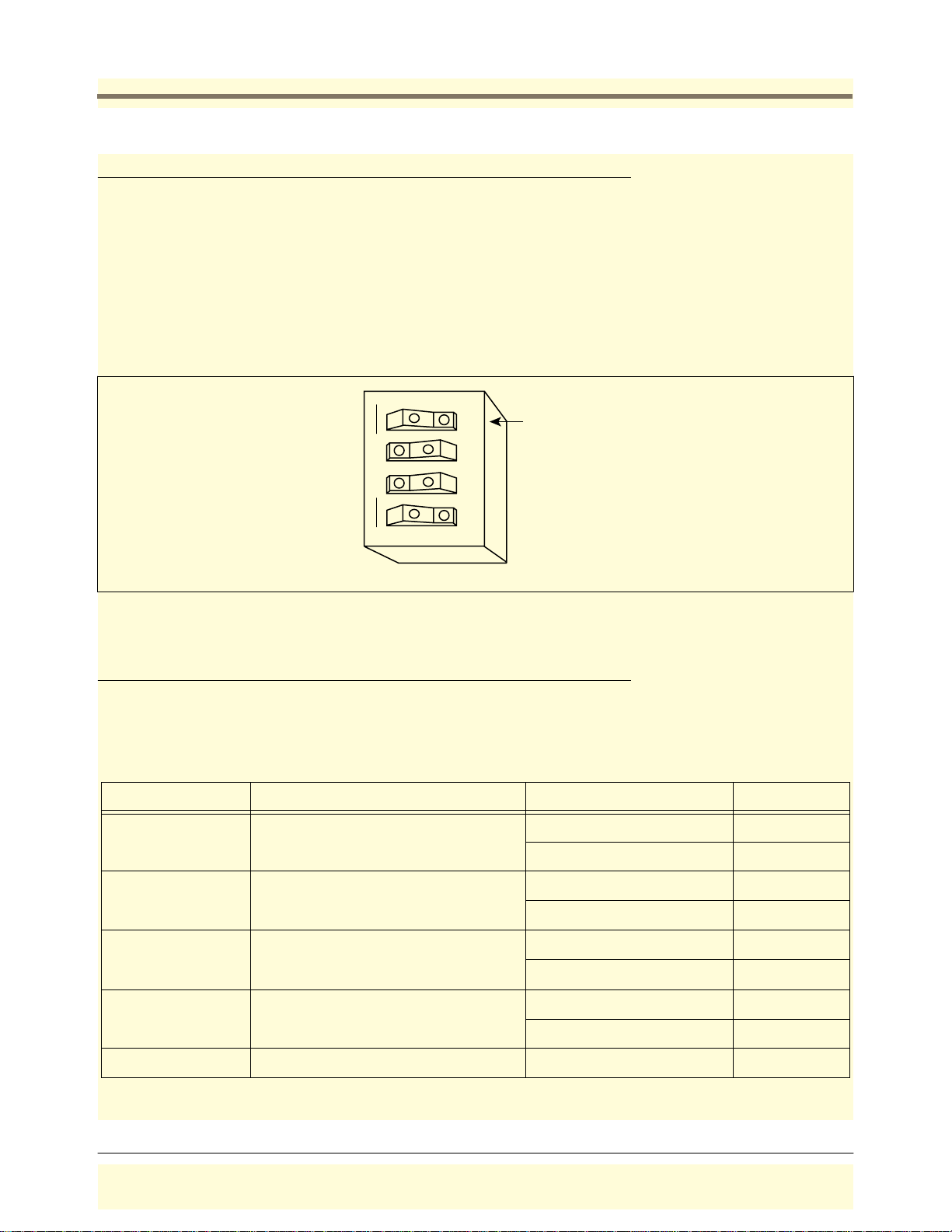
1. It is the customer’s responsibility to file a claim with their carrier.
2. Customer may submit a replacement purchase order. Customer is responsible for all charges and freight associated with
replacement order. Customer Service will work with production facility to have the replacement product shipped as soon as
possible.
3. If “lost” equipment is delivered at a later date and is not needed, VR will allow a Return to Stock without a restocking fee.
4. VR will NOT be responsible for any compensation when a customer chooses their own carrier.
RETURN SHIPPING
For the parts return procedure, please follow the appropriate instructions in the "General Returned Goods Policy" and "Parts Return"
pages in the "Policies and Literature" section of the Veeder-Root North American Environmental Products price list.
©Veeder-Root 2006. All rights reserved
.
ii
Page 3

Table of Contents
Table of Contents
Introduction
Relat e d Ma n ua l s ............ .. .......... ... .. .......... .. .......... .. ... .......... .. .......... .. ... ......... ... ......... ... ....2
Safety Symbols .................................................................................................................2
Site Considerations
Control Drawing ................................................................................................................3
National Electrical Code Compliance .. .. .......... .. .. .................... .. ...................... .......... .. ......4
Probe-to-Console Wiring..........................................................................................4
Shielded Cable or Veeder-Ro ot Di rect Burial Cable Required ................... .. .4
Wire Length ....................................................................................................4
Splices ...........................................................................................................4
Wire Gauges - Color coded ...........................................................................4
Power Wiring ............................................................................................................4
Probe Ju n c tion Boxes . .......... .. .. .......... ... ......... ... .. .......... .. .......... ... .. .......... .. .......... .. ..4
Probe W ir in g Sa fe t y Is s ue s ....... ... ......... ... .. .......... .. .......... ... .. .......... .. .......... .. ... ......... ... .... 5
Selec ti n g a Con so l e L oc a ti o n ......... .. .......... ... .. .......... .. .......... .. ... .......... .. .......... .. ... ......... ..5
Console Installation
Mounting the Con s o le .............. .. ... ......... ... ......... ... .. .......... ... ......... ... .. .......... .. .......... .. .......7
Wirin g th e Con s o le ...... ......... ... .. .......... .. .......... .. ... .......... .. .......... .. ... ......... ... .......... .. .. ....... 9
Probe Installation
Probe M a n ho le In s ta ll at i o n ........ ... .. .......... .. .......... .. .......... ... .. .......... .. .......... .. ... ......... ... ..10
Determining Mag Probe Length for Installation in a Dedicated Riser ............................ .10
Probe In stallatio n ......... .. .......... .. ... ......... ... ......... ... .......... .. ... ......... ... ......... ... .. .......... .. ..... 10
Spec ia l In s tru c ti o ns fo r U S T ’s wit h Meta l Ris e r C a ps ..... .......... ... ......... ... .. .......... ..12
Installing Field Wiring from Probes to TLS-50 Console ..................................................13
Buried Rigid Conduit .......................................................................................................13
Sealing Field Connections......................................................................................14
Direct Burial Cable - Probe to Console Field Wiring .......................................................15
Direc t B ur ia l C a bl e Fie ld Wiring..... .......... .. .......... ... .. .......... .. .......... .. ... .......... .. .......15
Connecting Probes to the Consol e ................... .......... .. .......... .. .......... .................... .. ......16
Precautions To Follow When Connecting Probes to TLS-50 Console ...........................16
Input/Output Wiring Positions and Label ing .................................... .......... .......... ...16
Wirin g A ssignments ..... .. .......... ... ......... ... .. .......... .. .......... ... ......... ... .. .......... ..16
Grounding Probe Shields and Drain Wires ..................................................17
Connecting Probes to the Consol e - Observe Polarity......................... .. .......... .. ....17
Syste m S et u p S e curity ............ ......... ... .......... .. .. .......... ... ......... ... .. .......... .. .......... ... .. .......18
Overfill Alarm Relay ........................................................................................................18
Applyi ng Po wer to Sys tem
Cold Boot - Initial Power Up (Consoles w/Display) .........................................................20
Cold Boot - Initial Power Up (Consoles w/o Display) ......................................................20
Cold Boot - RAM Clear ...................................................................................................20
Cons o le s with Display ....... ... .. .......... .. .......... .. ... .......... .. .......... .. ... ......... ... ......... ... ..20
Cons o le s Wi th o ut Di sp la y .. .......... .. .......... .. ... .......... .. .......... .. ... ......... ... .......... .. .. ..... 2 0
Warm B oo t .............. .. .......... .. ... ......... ... .......... .. .. .......... ... ......... ... .. .......... .. .......... ... .. .......21
Cons o le s with Display ....... ... .. .......... .. .......... .. ... .......... .. .......... .. ... ......... ... ......... ... ..21
Cons o le s without Disp la y ....... .. ... .......... .. .......... .. ... ......... ... .......... .. .. .......... ... .........21
iii
Page 4

Table of Contents
RS-232 Communications
RS-232 Peripheral Equipment Requirements .................................................................22
RS-2 3 2 Co nn e c ti on s . .......... .. .......... .. ... .......... .. .......... .. ... ......... ... .......... .. .. .......... ... .........22
To a Devi ce Less Than 50 Feet fro m th e Con so l e... ... .. .......... .. .......... .. ... ......... ... ..22
To a Device More Than 50 Feet from the Console........................... .......... .......... .22
Surge P ro te c tion for Com mu n ication Dev ic e s ...... .. .......... ... .. .......... .. .......... .. ... ......... ... ..23
Syste m S er ia l S e cu r ity ..... ... .......... .. .. .......... ... ......... ... .. .......... .. .......... ... ......... ... .. .......... ..24
RS-2 3 2 Se ria l C o m mu n ic a tio n Se t up .... ... .. .......... .. .......... ... .. .......... .. .......... .. ... ......... ... ..24
DB-9 Connector Pin-Outs ......... .. ............ ............ ...................... .................................. ....25
RS-232 Commands
Function Code: 001 ....................... .......... .. .......... .......... .. .......... .......... ..................... .. ....27
Function Code: 003 ....................... .......... .. .......... .......... .. .......... .......... ..................... .. ....28
Function Code: 201 ....................... .......... .. .......... .......... .. .......... .......... ..................... .. ....29
Function Code: 205 ....................... .......... .. .......... .......... .. .......... .......... ..................... .. ....30
Function Code: 504 ....................... .......... .. .......... .......... .. .......... .......... ..................... .. ....31
Function Code: 50C ........................... .............................. .. .............................. .. .. .......... .32
Function Code: 50D ........................... .............................. .. .............................. .. .. .......... .33
Function Code: 50E .................... ............ .......... .. .......... ............ .......... .................... .. .. ....34
Function Code: 517 ....................... .......... .. .......... .......... .. .......... .......... ..................... .. ....35
Function Code: 601 ....................... .......... .. .......... .......... .. .......... .......... ..................... .. ....36
Function Code: 604 ....................... .......... .. .......... .......... .. .......... .......... ..................... .. ....37
Function Code: 605 ....................... .......... .. .......... .......... .. .......... .......... ..................... .. ....38
Function Code: 606 ....................... .......... .. .......... .......... .. .......... .......... ..................... .. ....39
Function Code: 607 ....................... .......... .. .......... .......... .. .......... .......... ..................... .. ....40
Function Code: 608 ....................... .......... .. .......... .......... .. .......... .......... ..................... .. ....41
Function Code: 609 ....................... .......... .. .......... .......... .. .......... .......... ..................... .. ....42
Function Code: 60A .................... ............ .......... .. .......... ............ .......... .................... .. .. ....43
Function Code: 621 ....................... .......... .. .......... .......... .. .......... .......... ..................... .. ....44
Function Code: 624 ....................... .......... .. .......... .......... .. .......... .......... ..................... .. ....45
Function Code: 628 ....................... .......... .. .......... .......... .. .......... .......... ..................... .. ....46
Function Code: 638 ....................... .......... .. .......... .......... .. .......... .......... ..................... .. ....47
Function Code: 881 ....................... .......... .. .......... .......... .. .......... .......... ..................... .. ....48
Function Code: 882 ....................... .......... .. .......... .......... .. .......... .......... ..................... .. ....49
Function Code: 883 ....................... .......... .. .......... .......... .. .......... .......... ..................... .. ....50
Function Code: 884 ....................... .......... .. .......... .......... .. .......... .......... ..................... .. ....51
Function Code: 902 ....................... .......... .. .......... .......... .. .......... .......... ..................... .. ....52
Function Code: A01 .................... .................... .. .......... .. .......... .. .......... .................... .. ......53
Function Code: A02 .................... .................... .. .......... .. .......... .. .......... .................... .. ......54
Function Code: A10 .................... .................... .. .......... .. .......... .. .......... .................... .. ......55
Function Code: A11 .................... .................... .. .......... .. .......... .. .......... .................... .. ......56
Function Code: A12 .................... .................... .. .......... .. .......... .. .......... .................... .. ......57
Troubleshooting
Dual-Function Front Panel Keys (consoles w/Keypads Only) ........................................58
Probe Troubleshooting ...................................................................................................58
consoles w/o Disp la y.............. .. ... .......... .. .......... .. ... ......... ... .......... .. .......... .. ... .........58
Cons o le s w/D i sp lay......... .. .......... .. ... ......... ... .......... .. ... ......... ... ......... ... .. .......... .. ..... 5 8
Probe D ia g no s ti c R e p or t ........ ......... ... .. .......... ... ......... ... .. .......... .. .......... .. ... ..61
Replacing the CPU Board ...............................................................................................61
PROM Chip Replacement (Software Upgrade) ..............................................................63
Replacing the Power Supply Boar d ........ .......... .. .................... .. .......... ............ .......... .. ....66
iv
Page 5

Table of Contents
Figures
Console Specifications
Physical Specifications...........................................................................................67
Environmental Specifications .................................................................................67
Elect ric a l S p ec if ic a tio n s............ ... .. .......... .. .......... ... .. .......... .. .......... .. ... .......... .. .......67
Signal Input Specifications .....................................................................................67
Signa l Ou tp u t S p ec if ic a tio n s ........ .. .......... .. ... .......... .. .......... .. ... ......... ... .......... .. .. .....67
Front Panel User Interface (Consoles w/ Display)......... .......... .. .......... .. .......... .. ......67
Probe Circuit Codes ........................................................................................................68
Appendix A: TLS-50 and TLS-50C Safety Instructions ...................... A-1
Figure 1. Locating the console form number.............................................................1
Figure 2. Control Drawing - Example TLS-50 System Site Layout............................3
Figure 3. Re com m ended Mounting of Console............................................... .. ........7
Figure 4. Co nsole Dimensions and Designated Conduit Knockouts............... .. ........8
Figure 5. Wiring AC Power to the Console................................................................9
Figure 6. Determining the Minimum Mag Probe Length. .........................................10
Figure 7. TLS-50 Probe Installat ion Example - Underground Stor age Tank...........11
Figure 8. TLS-50 Probe Installat ion Example - Above ground Storage Tank..........11
Figure 9. Installing the Riser Adapter ......................................................................12
Figure 10. Example Probe Wiring Run in Buried Rigid Conduit................. .. .. ...........13
Figure 11. Probe Field Wiring Connection.................................................................14
Figure 12. Epoxy Sealing Connections.............. .......... .......... .. .......... .. .......... ...........14
Figure 13. Example Probe Wiring Run via Direct Burial Cable................................ .15
Figure 14. Probe Installation Directory......................................................................17
Figure 15. Connecting Prob e Wiring to Console .......... .. .......... .. .. .......... .. .......... .. ....17
Figure 16. DIP switch 4 in closed posi tion to enable menu lockout.............. .......... ...18
Figure 17. Connecting I/O Devices to Console........................ .......... .. .................... .19
Figure 18. Console Connected to a Remote Device via Short-Haul Modem ............23
Figure 19. Console Dip Switch Settings....................................................................24
Figure 20. DB9, RS-232 Pin-Outs .............................................................................25
Figure 21. Dual-Function Keys..................................................................................58
Figure 22. Diagnos tic Menu - Over v ie w ..... .. ... .......... .. .......... .. ... ......... ... .......... .. .......59
Figure 23. Diagnos tic Menu - Explanation ......... ... .......... .. .. .......... ... ......... ... .. .......... ..60
Figure 24. CPU Board Voltage Test Point s (Keypad/Display vers ion shown).......... .62
Figure 25. Removing PROM Chip.............................................................................64
Figure 26. Replacing PROM Chip (Keyp ad/Display version shown).........................65
v
Page 6

Introduction
Label on top of console
This manual describes the site preparation and console installation procedures for all TLS-50 Monitoring Systems.
Except where noted, the procedures described herein apply to all consoles. TLS-50 is used throughout Table 1
lists the various TLS-50 consoles and options by form number. Figure 1 shows where on the top of the console
you can find the information about your console’s form number.
Table 1.- TLS-50 Consoles and Features
Console Form No. Console T ype
8469X0-060 TLS-50 w/keypad and display, up to 6 probes
8469X0-160 TLS-50 w/keypad and display, w/relay, up to 6 probes
8469X0-260 TLS-50 w/keypad and display, w/com and relay, up to 6 probes
8469X0-230 TLS-50C w/o keypad or display, w/com, up to 3 probes
8469X0-460 TLS-50 w/o keypad or display, w/com and relay, up to 6 probes
MANUFACTURED BY:
VEEDER-ROOT, 125 POWDER FOREST DR.
SIMSBURY, CT. 06070 U.S.A.
FORM NO.: 846960-XX0
SERIAL NO.: XXXXXXXXXXXXXX
consoles\formlabel.eps
Console Form No.
Figure 1. Locating the console form number
This manual assumes that you installing the monitoring system in a new site (before pavement is put down and
with no wiring runs in place). Some of the topics covered in this manual are listed below.
•
Laying out the site
•
Mounting the console and connecting power wiring
•
Assembling and installing probes
•
Installing wiring conduit between the console and probes
•
Field wiring probes
•
Connecting probes to the console
•
RS-232 serial communication connection requirements and available serial commands (consoles with com
option)
•
Troubleshooting information
1
Page 7
Introduction Related Manuals
•
TLS-50 system specifications
After the console is wired to its power source and probes, you should program the console following the setup
instructions contained in the TLS-50 Setup & Operation Manual.
Related Manuals
577013-609 TLS-50 Setup & Operation Manual
576013-635 RS-232 Serial Interface Manual
576013-859 Direct Burial Cable Installation Manual
577013-744 Mag Plus Probe Assembly Guide
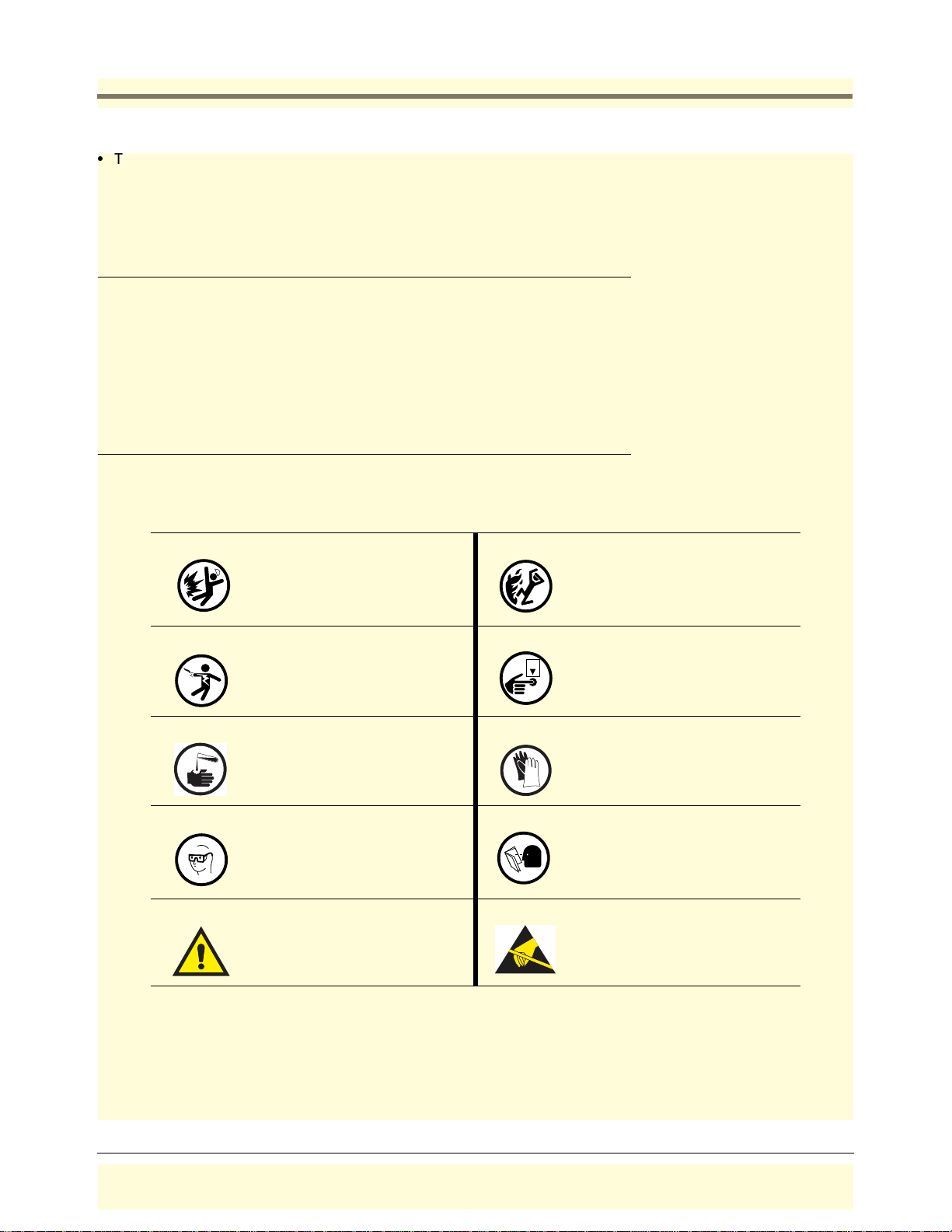
Safety Symbols
The following safety symbols are used in this manual to alert you to important safety hazards and precautions.
EXPLOSIVE
Fuels and their vapors are extremely
explosive if ignited.
ELECTRICITY
High voltage exists in, and is supplied
to, the device. A potential shock hazard exists.
INJURY
Careless or imp roper handling of
materi als can resul t in bo di ly injury.
WEAR EYE PROTECTION
Fuel spray from residual pressure in
the lines can cause serious eye injuries. Always wear eye protection.
WARNING
Heed the adjacent inst ructions to
av oi d equ ip me nt d amage or pe rson al
injury.
FLAMMABLE
Fuels and their vapors are extremely
flammable.
TURN POWER OFF
OFF
Live power to a device creates a
potential shock hazard. Turn Off
power to the device and associated
accessories when servicing the uni t.
GLOVES
Wear gloves to protect hands from
irritation or injury.
READ ALL RELATED MANUALS
Knowledge of all rel ated procedures
before you begi n wo rk is impor t an t .
Read and understand all manuals
thoroughly. If you do not underst an d
a procedure, ask someone who does.
STATIC SENSITIVE COMPONENTS
Handling static se ns itive electr o nic
components without grounding your
body can subject them to damaging
voltage po tentials.
2
Page 8
Site Considerations
g
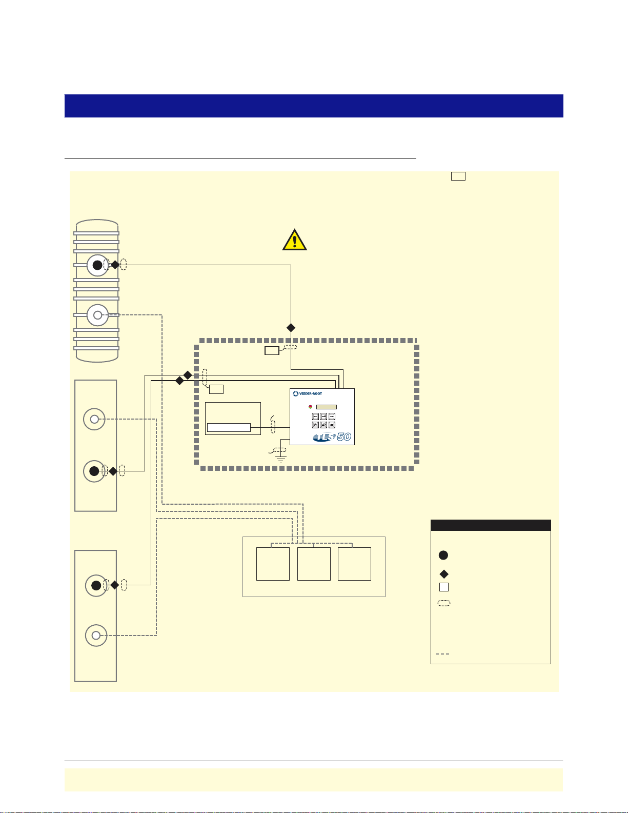
Control Drawing
Double Wall Tank
MP
MP
I.S.
Circuit breaker panel
or Fused, switched,
neon indication spur
120 or 240 Vac
12 AWG barrier
ground wire
I.S.
NOTE: Intrinsically safe wiring (marked ) shall be installed in
accordance with Article 504-20 of the NEC, ANSI/NFPA 70.
Note: conduit requirements are dependent on local electrical regulations.
For probe-to-console wiring, shielded cable is required regardless of
conduit requirements.
WARNING:
Substitution of components may impair intrinsic safety.
Circuitry within the TLS-50 Console barrier forms an intrinsically safe,
energy-limited system. This system makes TLS-50 probes safe for use in
a Class I, Group D hazardous location. TLS-50 probe wiring is intrinsically
safe only when connected to Veeder-Root's TLS-50 Consoles. Reference
Form Number 8469 (TLS-50/TLS-50C Consoles) and Form Number
8462, 8463, 8468, and 8473 (Probes).
I.S.
Non-Hazardous
Area
ALL FUNCTIONS NORMAL
PA
T1 VOL: 9889 GAL
Hazardous
Area
TLS-50
Single Wall Tank
MP
le Wall Tank
Sin
DP
DISPENSERS
Hazardous Area
LEGEND
Magnetostrictive Probe
MP
Expoxy Sealed Connection in
a Weatherproof Junction Box
Seal-Off
Terminal Connection
1/2'' (12.7 mm) Rigid Conduit
IS
Conduit Enters Console in an
Intrinsically Safe Area Knockout
PA
Conduit Enters Console in a
Power Area Knockout
Product piping
consoles\50sysdia.eps
Figure 2. Control Drawing - Example TLS-50 System Site Layout
3
Page 9

Site Consid era tion s National Electrical Code Compliance
National Electrical Code Compliance
The following information is for general reference and is not intended to replace recommended National Electric
Code (NEC) procedures. It is important for the installer to understand that electrical equipment and wiring located
in Class I, Division 1 and 2 installations shall comply with the latest appropriate articles found in the National
Electric Code (NFPA 70) and the Automotive and Marine Service Station Code (NFPA 30A), or other local code
such as the CEC, Canadian Electrical Code.
PROBE-TO-CONSOLE WIRING
Shielded Cable or Veeder-Root Direct Burial Cable Required
To ensure the best operating systems available, Veeder-Root REQUIRES the use of shielded cable for all probes
regardless of conduit material or application. In these installations, shielded cable must be rated less than 100 pF/
foot (100 pF/304 mm) and be manufactured with a material suitable for the environment, such as Carol
or Belden
™
88760, 876 0, o r 8770.
Note: Throughout this manual, when mentioning any cable being used for probe-to-console wiring, it will be
referring to shielded cable.
Wire Length
Improper system operation could result in undetected potential environmental and health hazards if the probe-toconsole wire runs exceed 1000 feet (304 m). Wire runs must be less than 1000 feet to meet intrinsic safety
requirements.
™
C2534
Splices
Veeder-Root recommends that no splices be made in the wire run between a probe junction box and the console.
Each splice degrades signal strength and could result in poor system performance.
Wire Gauges - Color coded
•
Shielded cable must be used in all installations. Probe-to-console wires should be #14 - #18 AWG (2.5 to 0.8
2
) stranded copper wire and installed as a Class 1 circuit. As an alternate method when approved by the
mm
local authority having jurisdiction, #22 AWG (>0.3 mm
2
) wires such as Belden 88761 may be suitable in
installations with the following provisions:
- Wire run is less than 750 feet (228 m)
- Capacitance does not exceed 100 pF/foot (100 pF/304 mm)
μ
- Inductance does not exceed 0.2
•
Total cable length per installation: 22,000 feet (6700 m).
H/foot (0.2 μH/304 mm)
POWER WIRING
2
Wires carrying 120 or 240 Vac from the power panel to the console should be #14 AWG (2.5 mm
for line, neutral and chassis ground (3); and #12 AWG (4 mm
2
) copper wire for barrier ground (1).
) copper wire
PROBE JUNCTION BOXES
Weatherproof electrical junction boxes with a gasketed cover are required on the end of each probe conduit run at
the manhole location. Gasketing or sealing compound must be used at each entry to the junction box to ensure a
waterproof junction. The interior volume of each junction box must be a minimum of 16 cubic inches (262 cm
3
).
Veeder-Root recommends the following junction box or equivalent:
•
Appleton Electric Co. - JBDX junction box, JBK-B cover, and JB-GK-V gasket.
•
Crouse-Hinds Co. - GRFX-139 junction box, GRF-10 cover, and GASK-643 gasket.
4
Page 10
Site Consid era tion s Probe Wi ring Safety Issues
Probe Wiring Safety Issues
WARNING
Probes operate in area s wher e flammabl e li quid s and ex plos ive v apors may be
present.
Improper installation may result in fire or explosion causing serious injury or
death.
Practice the following:
1. Read thoroughly and f ollow the instructions shipped with each probe.
2. Probe wiring must enter the consol e only thr ough their designated areas.
3. Power wires and condui t must not enter the intrinsically safe
compartment of the console.
4. Substitution of components may impair intrinsi c safety.
Wiring between the console and the probes is of limited electrical power so that there is insufficient energy to
ignite fuel. In the console, the low power probe wiring is considered intrinsically safe because it is physically
isolated from all high power wiring. To maintain the integrity of this safety feature probe wiring can not share the
same conduit with power wiring. In addition, probe cables can only enter the console through the designated
intrinsically safe area knockouts.
If the TLS-50 System is being retrofitted into a paved site, you can cut grooves in the pavement, run direct burial
cable to the probes, and then seal over the cable grooves, subject to approval of the local authority having
jurisdiction.
Before trenching, you should diagram all conduit runs between the console’s intended location and its deployed
probes. Your site diagram will help you calculate conduit and wiring lengths, and necessary quantities of junction
boxes, sealing boxes, clamps, brackets, etc.
Throughout this planning process and in the actual installation, you must follow all latest National Electric Codes,
and applicable federal, state, and local codes as regards conduit type, depth below grade, sealing, grounding,
wire capacities, direct burial (if permitted), etc.
Selecting a Console Location
WARNING
Explosive vapors or flammable liquid s could be pre sent near locations where
fuels are stored or being dispensed. The TLS-50 Console is not explosion
proof.
An explosion or fire resulting in serious injury or death, property loss and
equipment damage could occur if the console is installed in a volatile,
combustible or explosive atmosphere (Class I, Division 1 or 2).
Do not install this c onsole in a v olatile, comb ustib le, or e xplosiv e atmosph ere.
5
Page 11
Site Consid era tion s Selecting a Console Location
Select a mounting location on the inside of any building. The console must be protected from severe vibration,
extremes in temperature and humidity, rain, and other conditions that could harm computerized electronic
equipment.
The equipment is designed to operate safely under the following range of conditions:
•
Temperature range 0 to 40°C - ( storage temperature range of -40 to +74°C).
•
A maximum relative humidity of 95% RH (non-condensing) at temperatures up to 40°C.
•
Console may be powered by either 120 or 240 Vac. A switchmode power supply automatically detects the
input voltage (no jumpers required).
•
Main supply voltage fluctuations not exceeding ±10%.
•
Pollution Degree Category 2.
•
Installation Category II.
Important! Consoles must be installed within the interior of buildings. They are not suitable for any external
location.
Ensure that the console is located where neither the console nor its associated cabling will be damaged by doors,
furniture, barrows, etc. Consider the ease of routing wiring, ducting, and probe cables to the console. Check that
the mounting surface is strong enough to support the console’s weight of about 4 pounds.
Important! If the unit requires cleaning, do not use any liquids, wipe only with a clean, dry cloth.
6
Page 12
Console Installation
consoles\tls-50\50mnt.eps
T
O
s
f
m
d
Mounting the Console
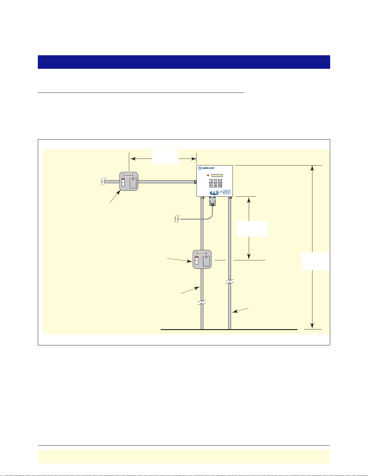
Figure 3 illustrates recommended console mounting. Install the console fastening devices to the mounting surface
using the hole pattern (6.7” x 5.7”) shown in Figure 4. Mounting screws up to 3/16” diameter may be used.
Install metal conduit (1/2” I.P.S.) between the console and the power panel. Figure 4 shows the three designated
knockouts (one each on top, left side, and bottom) through which power wiring can safely enter the console.
1000 mm
(Maximum)
ALL FUNCTIONS NORMAL
T1 VOL: 9889 GAL
TLS-50
o an external alarm (i.e., Forecourt Alarm)-
ne 2 ampere fused, switched, neon indication
pur or a dedicated circuit breaker rated
or 120 Vac or 240 Vac. NOTE, circuit breaker
ust be marked as the external alarm
isconnect for the console.
One 5 ampere fused, switched, neon
indication spur (for 240 Vac), or a dedicated
circuit breaker rated for 15 amperes, 120 Vac
or 240 Vac. NOTE, circuit breaker must be
marked as the power disconnect for the console.
From an independent 24 hour supply at the distribution
panel, run three 2.5 mm (minimum) standard color coded
wires; live, neutral, and earth, to the fused spur. Run one
4 mm wire, color coded green/yellow, from the earth bus
bar at the distribution panel direct to the console location.
Leave at least 1 metre of free cable for connection to the
console.
Communication
cable
1000 mm
(Maximum)
1500 mm
(Maximum)
Conduit for probe
field cables
Figure 3. Recommended Mounting of Consol e
7
Page 13

Console Installation Moun tin g the Co ns ol e
)
5.3''
(
(30 mm)
0.7''
17,8)
consoles\tls50dimen.eps
6.4''
(163 mm)
0.93''
(23,6 mm)
0.93''
(23,6 mm)
0.34''
(8,6 mm) typ.
5.7''
(145 mm)
(135 mm)
7.4"
(188 mm)
6.7"
(170 mm)
2.6''
(66)
0.22'' (5,6 mm) dia.
console mounting
holes (4 places)
0.93''
(24 mm)
1/2-inch IPS and .56 inch (22 & 14 mm)
Power wiring only - conduit knockouts
(4 places)
1.25''
(32 mm)
3.75"
(95mm)
1/2, 3/4, & 1 inch IPS (22, 28, & 35 mm)
Intrinsically safe wiring only - conduit knockouts
(2 places)
0.93''
0.4''
(10 mm)
(24 mm)
1.18''
2" (51 mm
Figure 4. Console Dimensions and Designated Conduit Knockouts
8
Page 14
Console Installation Wiring the Console
A
t
A
w
Wiring the Console
WARNING
The console contains voltages which can be letha l. It is connected to devices
that must be intrinsically safe.
Connecting power wires to a live circuit can cause electrical shock that may
resul t in serious inju r y o r dea th.
OFF
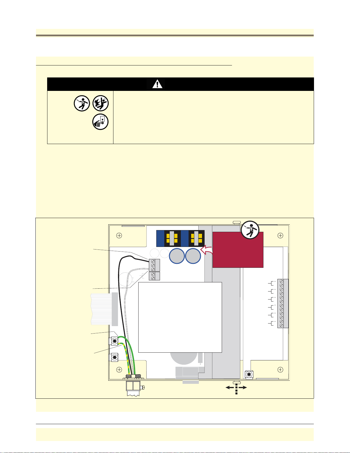
1. Turn power off at the circuit breaker connecting the power supply wires.
2. Attach conduit from the power panel to the console's Power Area
knockouts only (1 on top and bottom, ref. Figure 4).
1. Pull four wires between the power panel and the console; three #14 AWG color-coded wires for AC line (L),
AC neutral (N) and chassis ground; and one #12 AWG (4 mm
2
) green and yellow wire for barrier ground.
For international applications using 240 Vac, pull four wires between the power panel and a 5 A fused,
switched, neon indication spur; three #14 AWG color-coded wires for AC line (L), AC neutral (N) and chassis
2
ground; and one #12 AWG (4 mm
) green and yellow wire for barrier ground. Pull four identical wires be-
tween the spur and the console.
2. Open the right door of the console and connect the four power/ground wires as shown in [Figure 5]. Do not
connect the power wires to breaker panel at this time.
L2 L4
WARNING!
ttach neutral wire to top
erminal ("N") of J4
CONSOLE
POWER
RELAY RATING
120/240 VAC
2 A MAX
Attach hot wire to bottom
terminal ("L") of J4
ttach chassis ground
ire to ground lug
N
J4
C24 C27
L
J5
1234
OPEN
SW1
SEC
SETUP
J3
POWER WIRING NOTES:
1. Barrier ground must be #12 AWG (4 mm
or larger diameter.
2. Check to be sure that the electrical resistance
between the console ground lug and a known
good earth ground is less than 1 ohm.
3. Connect the power supply wires in the power
panel to a separate dedicated circuit.
4. Electrical rating power input -- 120 Vac or
240 Vac, 50/60 Hz, 2 A maximum.
5. See the "Console Dimensions and Designated
Conduit Knockouts" figure for actual locations of
power conduit knockouts into the console. Power
wiring must enter only in Power Area conduit
knockouts.
Protective Earthing
Conductor (Green and
Yellow) Attach #12AWG
2
(4 mm
) barrier ground
wire to ground lug
Shock hazard. Do not
touch metal ends of
capacitors C24/C27
or the metal bands
on chokes L2/L4.
2
)
WARNING
SUBSTITUTION OF COMPONENTS
MAY IMPAIR INTRINSIC SAFETY.
NO REPAIRS SHOULD BE ATTEMPTED.
REFER SERVICING TO QUALIFIED
PERSONNEL ONLY.
PROBE 6
PROBE 5
PROBE 4
PROBE 3
PROBE 2
PROBE 1
AVERTISSEMENT
LA SUBSTITUTION DE COMPOSANTS
PEUT COMPROMETTRE LA SECURITE
INTRINSEQUE.
+
+
+
+
+
+
consoles\tls50\50powr.eps
Power
Side
Intrinsically
Safe Side
Figure 5. Wiring AC Power to the Console
9
Page 15
Probe Installation
Probe Manhole Installation
At each underground probe location, install a 14-inch (355 mm) minimum diameter approved manhole according
to the manufacturer’s instructions (Note: probes should be located at least 24 inches (610 mm) from the
submersible pump to avoid erroneous probe readings when the pump is running). Position the manhole so that
there is necessary clearance for junction box installation and wiring.
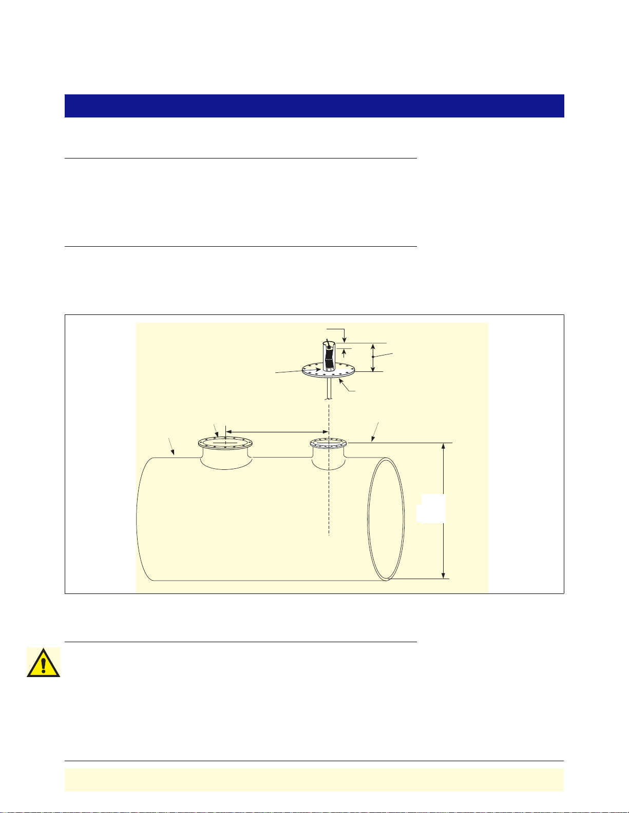
Determining Mag Probe Length for Installation in a Dedicated Riser
1. Measure the distance from the bottom of the tank to the top of the probe manway - this is the minimum probe
length (ref. Figure 6).
2. The probe canister must be within the riser pipe (minimum length of 10 inches [254mm]).
3" (76mm) min. clearance from
top of canister to top of riser
10" (254mm) minimum
riser length
Probe canister must
be within riser pipe
Manway cover
STP manway
Tank
probes\probemeasurement.eps
24" ( 610 mm) min.
Top of probe
manway
Minimum
Probe length
Figure 6. Determining the Minimum Mag Probe Length
Probe Installation
1. Turn OFF power to the console.
2. Remove any sludge from the bottom of the tank.
3. Check that floats, boot, and cable are assembled correctly on probe (ref. Mag Probe Assembly Manual).
4. Gently slide the float(s) to the bottom of the probe shaft before raising the probe. Carefully lower the probe into
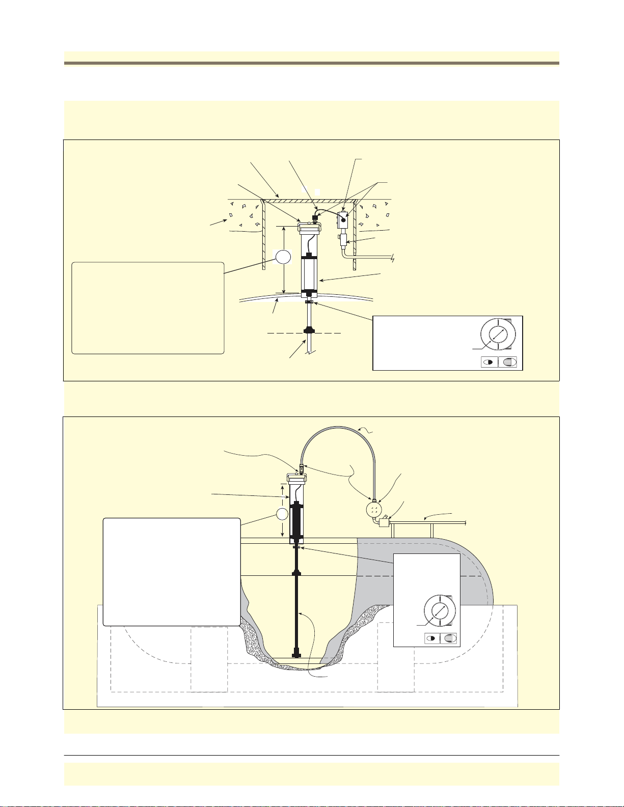
the riser pipe until the boot rests on the bottom of the tank [See Figure 7 for UST installation or Figure 8 for
AST installation].
10
Page 16
Probe Installation Probe Installation
e
CAUTION! Handle probes carefully. Striking or dropping the probe will result in loss of calibration and could
cause permanent damage.
14'' min. dia. manhole
Riser cap with cord grip
bushing and nut
Concrete slab or packed
earth per NFPA 80
A = 14" minimum for global mag
plus/mag plus probes. When
installing a probe longer than the
the tank diameter, increase this
minimum dimension to compensate.
(Example: a 7'-6'' diameter tank will
use an 8' probe, in which case you
must add 6" to minimum riser length
'A', i.e., 20").
Use bushing and body of grip
fitting supplied with probe and
Adaptor nut supplied with
AST kit.
Riser pipe: 2-, 3-, or 4'' API
schedule 40 - depending on
probe type
A = 14" minimum for global mag
plus/mag plus probes. When
installing a probe longer than the
the tank diameter, increase this
minimum dimension to compensate.
(Example: a 7'-6'' diameter tank will
use an 8' probe, in which case you
must add 6" to minimum riser length
'A', i.e., 20").
.
.
.
.
.
.
.
.
.
.
.
..
.
Tank
Mag Probe
(rests on bottom)
Probe cable
Weatherproof junction box with 1/2" NPT
threads (16 cubic inch minimum)
Cord grip seals
.
.
.
.
.
.
.
.
.
.
.
..
.
Seal-off, epoxy seal per NFPA spec
A
1/2" Rigid conduit (to Console)
Riser pipe: 2-, 3-, or 4'' API schedule 40
depending on probe type (To prevent
erroneous probe readings, install probe
riser a minimum of 24'' from the submersibl
pump.)
Split-Ring Collar
(P/N 576008-617)
required if probe
enters the riser.
Top view
3/4" ID
Side view
probes\pbinstcen.eps
Figure 7. TLS-50 Probe Installation Example - Underground Storage Tank
Flexible metal conduit
supplied with AST kit
Liquidtight
fittings from
AST kit
Weatherproof junction box with
1/2" NPT threads (16 cubic inch
minimum)
Epoxy seal per NFPA specs
A
Split-Ring Collar
(P/N 576008-617)
required if probe
enters the riser.
Top view
3/4" ID
Side view
Rigid conduit
probes\astpbins.eps
Mag Probe
(rests on bottom)
Figure 8. TLS-50 Probe Installation Example - Above ground Storage Tank
11
Page 17
Probe Installation Probe Installation
A
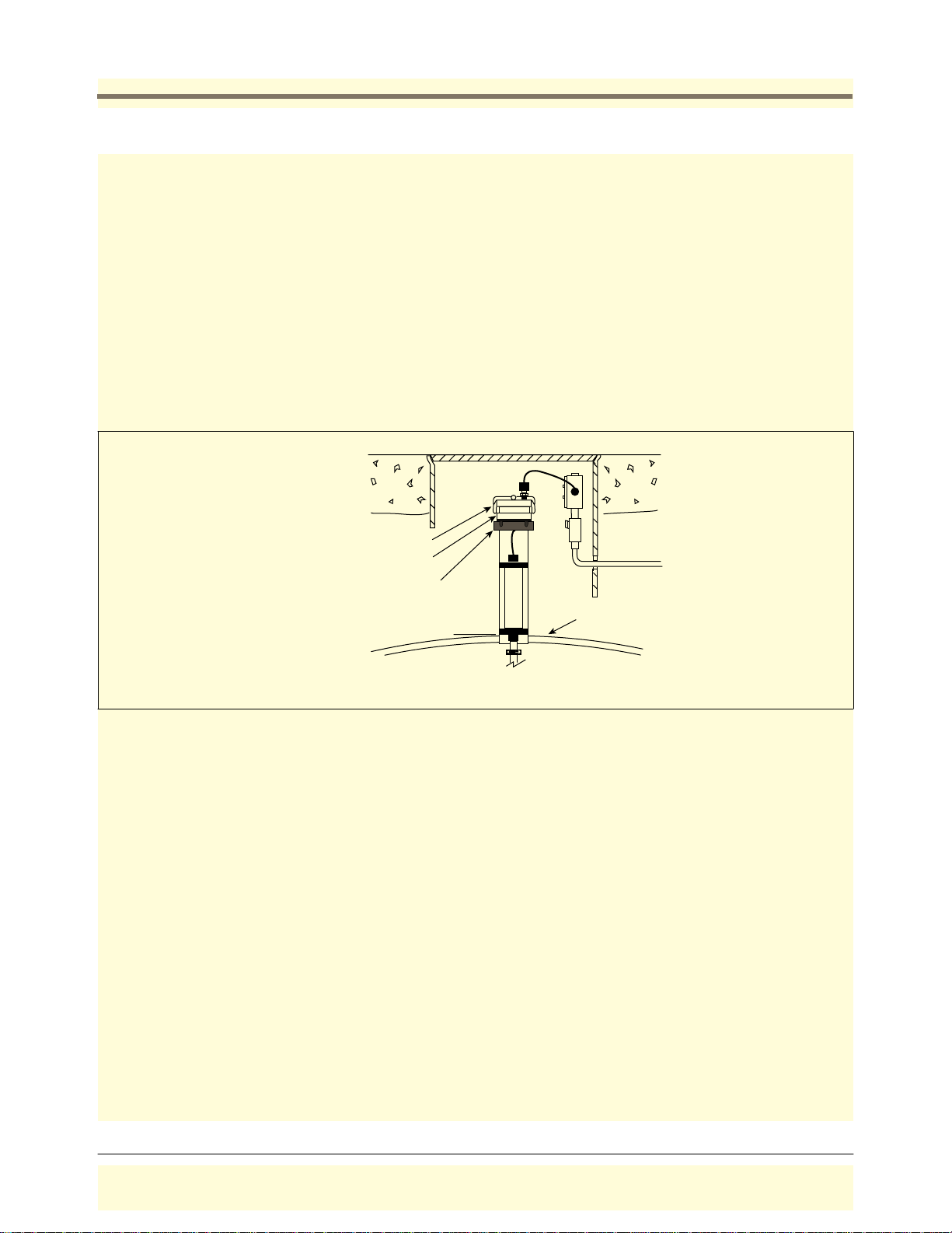
SPECIAL INSTRUCTIONS FOR UST’S WITH METAL RISER CAPS
If you are installing the metal cap and adapter ring, screw the ring onto the 4” riser until the gasket contacts the
pipe, then use a pipe wrench to tighten it an additional 3/4 turn. Push the cable through the metal cap and cord
grip, then clamp the cap onto the ring.
At sites that require installation of a riser adaptor (Phil-Tite M/F 4X4 or equivalent) at the top of the riser, do so
following the manufacturer’s instructions. Next screw the adapter ring from the Veeder-Root kit (
P/N 312020-952)
onto the riser adaptor by hand until the gasket contacts the sealing surface. Then use a torque wrench attached to
an appropriate strap wrench (K-D Specialty tools nylon strap oil filter wrench, or equivalent) and tighten the ring to
35 - 45 ft-lbs. Loosen the cord grip nut and push the cable through the metal cap and cord grip, then clamp the
cap onto the ring (see Figure 9).
Make sure there is a minimal amount of slack between the probe and cap, then tighten the cord grip nut until the
cable is held firmly. Push the end of the cable through the field J-box cord grip, then tighten that cord grip nut as
well. Splice and seal the wires in the J-box as shown in Figure 12.
.
.
.
.
.
.
.
.
.
..
Metal cap from kit
dapter ring from kit
Riser adaptor
(Phil-Tite M/F4X4,
or equivalent)
probes\riseradapt.eps
.
.
.
.
.
.
.
.
.
.
.
.
.
.
.
..
Tank
Figure 9. Installing the Riser Adapter
12
Page 18
Probe Installation Installing Field Wiring from Probes to TLS-50 Console
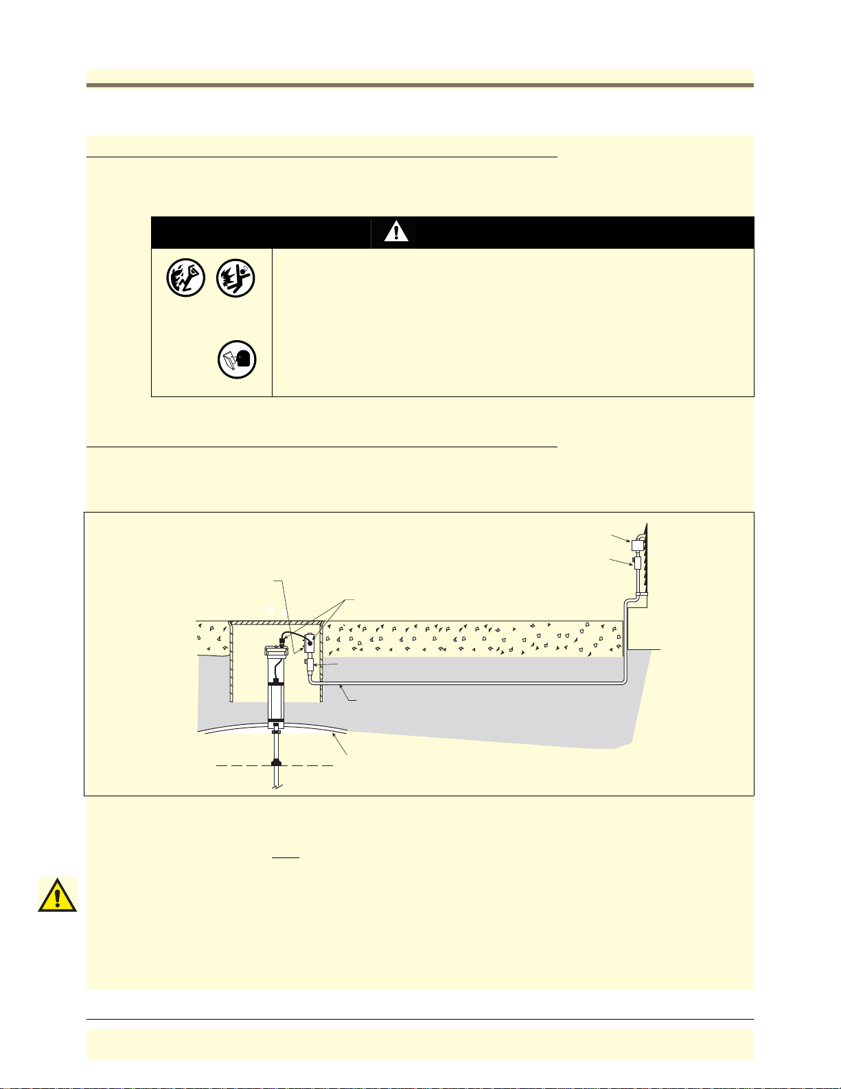
Installing Field Wiring from Probes to TLS-50 Console
Two wiring run methods are commonly used for probes - Shielded wiring pulled through buried, sealed 1/2” rigid
conduit (discussed in the following paragraphs); or direct burial cable (discussed on page 15).
WARNING
Probes operate in areas where flammable liquids and explosive vapors may be present.
Improper inst all atio n may res ult in fir e or explo si on causi ng se rious injury or death.
Practice the f ollowing:
1. Read thoroughly and follow the instructions shipped with each probe.
2. Probe wiring conduit must not contain any other wires.
3. Probe wiring and conduits must enter the console only through their designated
areas ( se e Figure 4).
4. Power and communication wires and conduit must not enter the intrinsically safe
compartment of the conso le. (see Fi gure 4).
Buried Rigid Conduit
The preferred method, especially in new sites before driveway surfaces are paved, is to pull probe wiring through
buried 1/2” rigid conduit [Figure 10].
Weatherproof junction
box with 1/2-inch N.P.T.
threads (16 cubic inch
Splice Closure
Seal-Off
minimum)
Cord grip seals
.
.
.
.
.
.
.
..
.
.
.
.
.
.
.
.
.
.
.
.
.
.
.
.
.
.
.
.
.
.
.
.
.
..
..
..
.
.
.
.
.
.
.
.
.
.
.
.
.
.
.
.
.
.
.
.
.
..
.
.
.
.
.
.
.
.
.
.
.
.
.
.
.
.
..
.
.
.
.
.
.
.
.
.
..
.
.
.
.
.
.
.
.
.
.
.
.
.
.
.
.
.
.
.
.
.
.
.
.
.
.
.
.
.
..
.
.
.
.
.
.
.
.
.
.
.
.
.
.
.
.
.
.
.
.
.
.
.
.
.
.
.
.
.
.
.
.
.
.
.
.
.
.
.
.
.
.
.
.
.
.
.
.
.
.
.
.
.
.
.
.
.
.
.
Epoxy seal per NFPA spec
1/2'' rigid conduit (to console)
Tank
probes\pconduit.eps
Figure 10. Example Probe Wiring Run in Buried Rigid Conduit
Pull shielded cable consisting of two conductors, color-coded #14-18 AWG stranded copper wire, between the
console and the junction box at each
probe location (do not gang wires together). Use single lengths of wire with
no splices to ensure optimum signal strength.
IMPORTANT! Maximum probe-to-console cable length is 1000 feet (305m).
Since wires for multiple probes may enter the console through a single conduit, it is recommended that you use a
different color-code for each wire or individually mark each wire to identify probe inputs. Also, if the intrinsically
safe wires enter the building in a wiring trough, only intrinsically safe wires (from TLS-50/-50C probes) can be in
the trough. Keep all low power (intrinsically safe) wiring physically isolated from high power wires in all wiring
troughs per the NEC.
13
Page 19
Probe Installation Buried Rigid Conduit
e
p
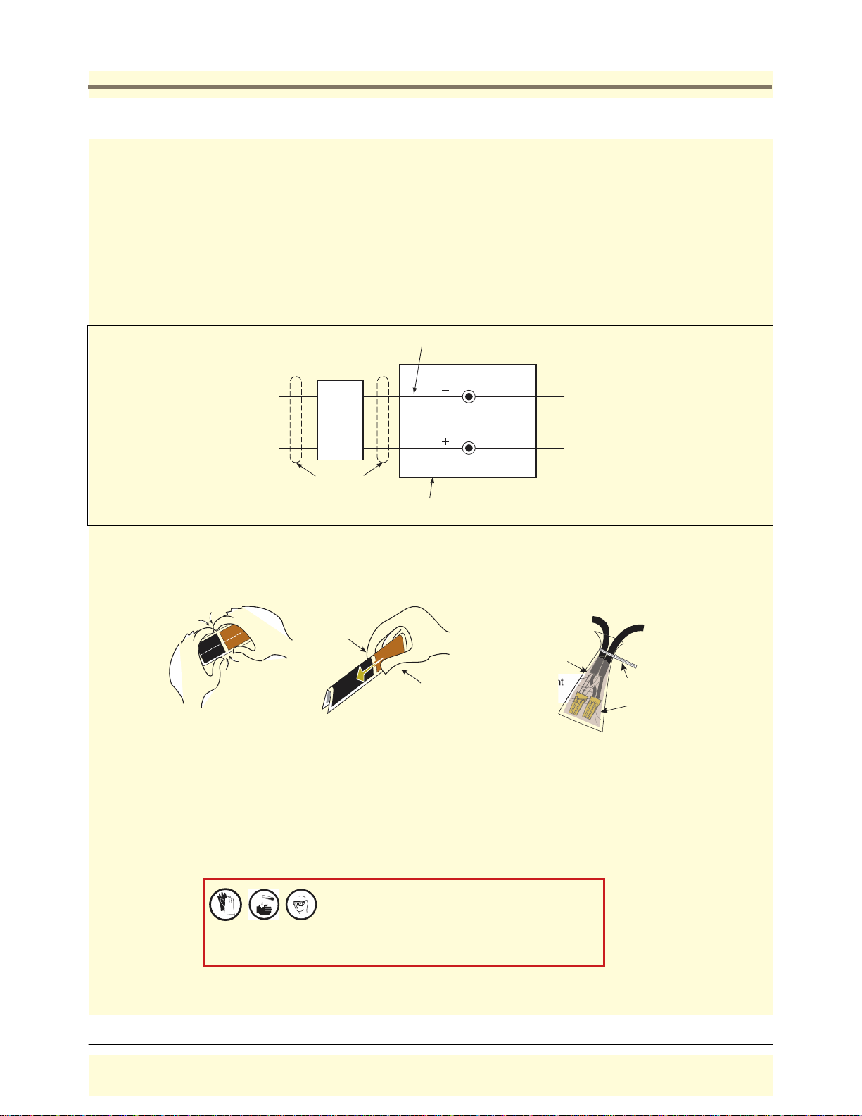
SEALING FIELD CONNECTIONS
1. Pull the wires from the probe canister into the junction box. Pull two wires from the console through the seal-off
box and into the junction box.
2. Using wire nuts, connect the two wires from the probe to the two wires coming from the console. Be sure to
observe color codes or tags when making these connections. Figure 11 diagrams a typical probe field wiring
connection in the junction box.
3. Do NOT terminate drain wire at this location, ground drain wire at console only.
4. Seal wire nuts with epoxy sealant using one bag for two-wire nut connections (Figure 12).
5. Push the tie-wrapped, epoxy sealed bag into the junction box. Replace and tighten the junction box cover.
Do not ground drain wire
in junction box
To
PROBE
Terminal
Seal-off
Block In
Console
1/2'' rigid
conduit
robes\3mpwir.eps
Epoxy sealed connections in a
weatherproof junction box
ACB
Instructions:
NOTE: When temperature is below 50˚F (10˚C), keep
resin in a warm place prior to mixing (e.g., in an
inside pocket next to body).
1. Open epoxy sealant package, and remove resin pak.
2. Holding resin pak as shown in A, bend pak along long
length.
3. As shown in B, firmly squeeze the RED SIDE of the
resin, forcing it through the center seal and into
BLACK SIDE.
Black
From
Prob
White
Figure 11. Probe Field Wiring Connection
From probe,
sensor, or
transducer
Make sure that
the ends of cable
sheathing are submerged in sealant
4. Mix thoroughly to a uniform color by squeezing
contents back and forth 25-30 times.
5. Squeeze mixed, warm resin into one end of bag and
cutoff other end.
6. Slowly insert wiring connections into sealing pack
until they fit snugly against the opposite end as
shown in C.
7. Twist open end of bag and use tie wrap to close it off
and position the tie wrapped end up until the resin
jells.
To console
Tie wrap
Wire nuts
CAUTION: Epoxy sealant is irritating to eyes, respiratory system,
and skin. Can cause allergic skin reaction. Contains: epoxy resin
and Cycloaliphatic epoxycarboxylate.
Precautions: Wear suitable protective clothing, gloves, eye, and
face protection. Use only in well ventilated areas. Wash
thoroughly before eating, drinking, or smoking.
consoles\epxy2w.eps
Figure 12. Epoxy Sealing Conn ect ion s
14
Page 20
Probe Installation Direct Burial Cable - Probe to Console Field Wiring
G
n.
Direct Burial Cable - Probe to Console Field Wiring
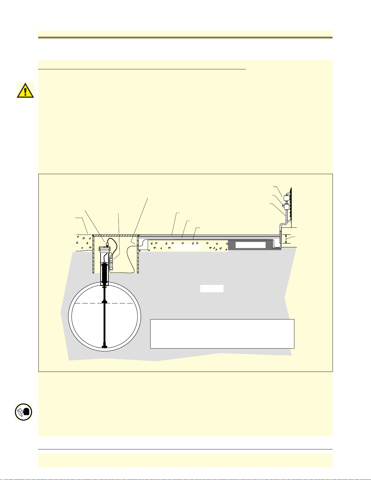
An alternative to trenching through existing pavement is to use direct burial cable.
IMPORTANT! Maximum probe-to-console cable length is 1000 feet (305m).
Prior to installing direct burial cable with epoxy splices, consult with the local authority having jurisdiction. Use of
direct burial cable is only allowed in locations where local codes permit the use of buried cable.
The direct burial method requires grinding a 1/4” to 3/8” wide by 1-1/4” deep groove (adding 1/4” of depth for
each additional cable) in the pavement surface, laying Veeder-Root supplied direct burial cable down in the bottom
of the groove, laying an expanded polyethylene foam backer rod over the cable(s), and then a placing a 1/4” to 1/
2” bead of Veeder-Root recommended silicone sealant over the backer rod to within a minimum of 3/8” below the
pavement surface [see Figure 13].
If you decide to use the direct burial method, you should order the Veeder-Root Direct Burial Cable Preparation
Kit, P/N 848100-500.
Splice closure
Cord grip
rade
.
.
.
..
Epoxy filled
splice
enclosure
Drill oversized hole
in manhole for cable
890-SL silicone sealant
SOF ROD backer rod
1
2
Direct burial cable
.
.
.
.
.
.
.
.
.
.
.
.
.
.
.
.
.
.
.
..
.
.
.
.
.
.
.
.
..
.
.
.
.
.
.
.
.
.
.
.
.
.
..
.
CONCRETE
.
.
.
.
.
.
.
.
.
.
.
.
.
.
.
.
.
..
.
.
.
.
.
.
.
.
.
.
.
.
..
.
.
.
.
.
.
.
.
.
.
.
.
.
.
.
.
.
.
.
.
.
.
.
.
.
.
.
.
.
.
.
.
.
.
.
.
.
.
...
Seal-off
Rigid conduit
3'' Mi
ASPHALT
EARTH
1
Dow Corning Silicone Pavement Sealant
2
Expanded polyethylene foam rod - trademark of
Applied-Extrusion Technologies.
probes\pdburial.eps
Figure 13. Example Probe Wiring Run via Direct Burial Cable
DIRECT BURIAL CABLE FIELD WIRING
When using direct burial cable for probe-to-console wiring runs, the wiring connections are the same as shown in
Figure 11 on page 14, but the sealing materials and procedure is completely different. If you are using Direct
Burial Cable you seal the field wiring connections as instructed in the Direct Burial Cable Installation Manual.
15
Page 21
Probe Installation Connecting Probes to the Console
Connecting Probes to the Console
WARNING
The equipment is used in location where lethal voltages and explosive vapors
or flammable fuels may be present.
Care must be taken when installing, servicing or replacing part s in the syst em
or serious injury or death from explosion, fire or shock may occur.
For this system:
1. Comply with the latest Nati onal Electric Code, feder al, state, and local
codes, and an y other a pplicab le safet y codes . In ad diti on, take necess ary
precautions during installation, service, and re pair to prevent personal
injury, property loss and equipm ent damage.
2. Refer servicing to trained and qualified personnel only.
3. Substitution of components may impair intrinsi c safety.
OFF
4. Be sure AC power is “Off” before opening the console panel cover and
connecting probe wires. Do not short any voltage across any barrier
terminal including probes.
Precautions To Follow When Connecting Probes to TLS-50 Console
To The Installer! You Must Read And Understand This Information.
INPUT/OUTPUT WIRING POSITIONS AND LABELING
In all cases, the devices wired to the console’s input/output terminal blocks must be recorded to prevent
improper replacement during installation or service. A circuit directory is listed below for this purpose.
During programming, the probes wired to each position are identified and stored in memory. If a probe is removed
and reconnected to a different set of input terminals after programming, the system will not properly recognize the
data being received.
Wiring Assignments
1. Identify all probe wires according to their terminal block location using the self-adhesive numbering labels
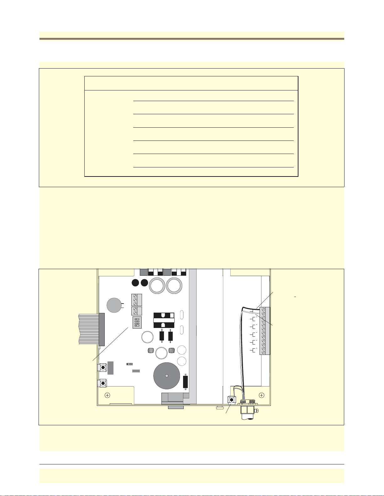
furnished. Accurately record on the circuit directory in Figure 14 the location of each probe as you attach
wires to the probe input terminal block.
2. Important! Once a device has been wired to certain terminals and the system has been programmed, the wires
from that device may not be relocated to other terminals without reprogramming the system.
16
Page 22
Probe Installation Precau t i on s To Follow When Conn ec ting Probe s to TL S- 50 Co ns ol e
consoles\tls50\prbtnk.eps
drain wire to grounding lug
Probe Number
PROBE 1 IN
TANK
TANK Number & Product
PROBE 2 IN TANK
PROBE 3 IN TANK
PROBE 4 IN TANK
PROBE 5 IN TANK
PROBE 6 IN TANK
Figure 14. Prob e Ins t al lation Dire ctory
Grounding Probe Shields and Drain Wires
Connect probe cable shields and drain wires to ground in the console only, not at the field junction boxes. Do not
ground both ends of the shield.
CONNECTING PROBES TO THE CONSOLE - OBSERVE POLARITY
Connect the two color-coded/marked wires from the each probe to the appropriate terminals of the Probe Terminal
Block as shown in Figure 15.
SW 1
SW1
WARNING
SUBSTITUTION OF COMPONENTS
MAY IMPAIR INTRINSIC SAFETY.
OPEN
J3
1234
SEC
SETUP
Attach probe cable shield and/or
NO REPAIRS SHOULD BE ATTEMPTED.
REFER SERVICING TO QUALIFIED
PERSONNEL ONLY.
PROBE 6
PROBE 5
PROBE 4
PROBE 3
PROBE 2
PROBE 1
AVERTISSEMENT
LA SUBSTITUTION DE COMPOSANTS
PEUT COMPROMETTRE LA SECURITE
INTRINSEQUE.
+
+
+
+
+
+
Black wire from probe
connects to terminal
White wire from probe
connects to + terminal
consoles\tls50\50prbwir.eps
Figure 15. Connecting Probe Wiring to Console (TLS-50C has 3 probe inputs only)
17
Page 23
Probe Installation System Setup Security
p
System Setup Security
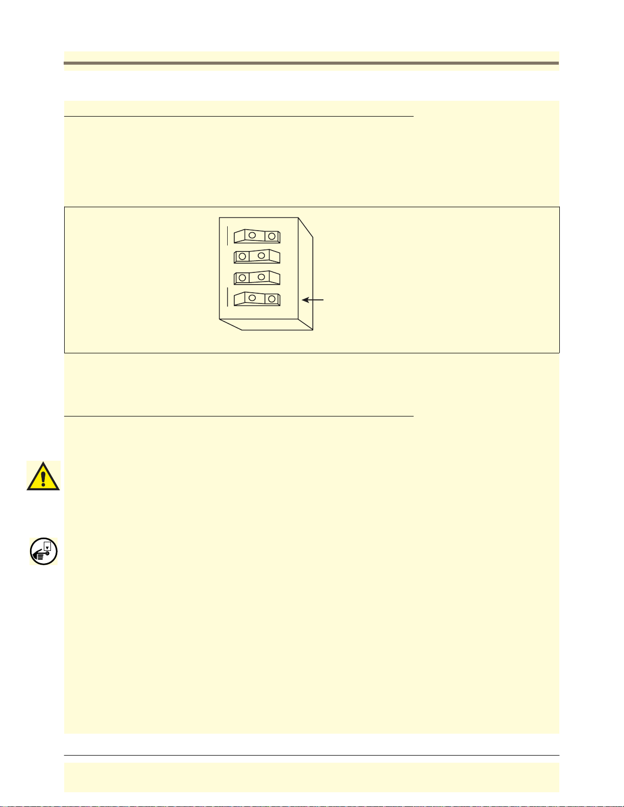
To protect against unauthorized access to system operation DIP switch 4 of SW1 on the Power Supply board lets
you lockout setup and diagnostic menus after making initial programming (for consoles w/display only). Consoles
are shipped from the factory with this switch in the open (disabled) position.
See Figure 15 for location of this switch. Figure 16 shows the switch in the closed position, enabling setup
lockout. Switch 2 and Switch 3 are not used and can be in any position.
1 2 3 4
OPEN
Sw 4 - blocks access to
SETUP
setup/diag menus after setu
(consoles w/display only)
consoles\tls50\sw4.eps
Figure 16. DIP switch 4 in closed position to enable menu lockout
Overfill Alarm Relay
All consoles except those having form numbers 8469X0-060 and 8469X0-230 have one dry contact relay output
that closes when an overfill alarm is activated. You can connect an external audible/visual warning device to this
relay.
Important! Note these Output Relay Connection Restrictions:
1. Do not connect output relays to a device that draws more than 2 amperes of current. Output power: output
relay contact, resistive load - 120/240 Vac, 2 A max.
2. Alarm relays cannot be used for flow control. Alarm relays provide only a momentary closure and cannot
actuate flow control devices such as valves and pump motor relays for extended periods of time.
OFF
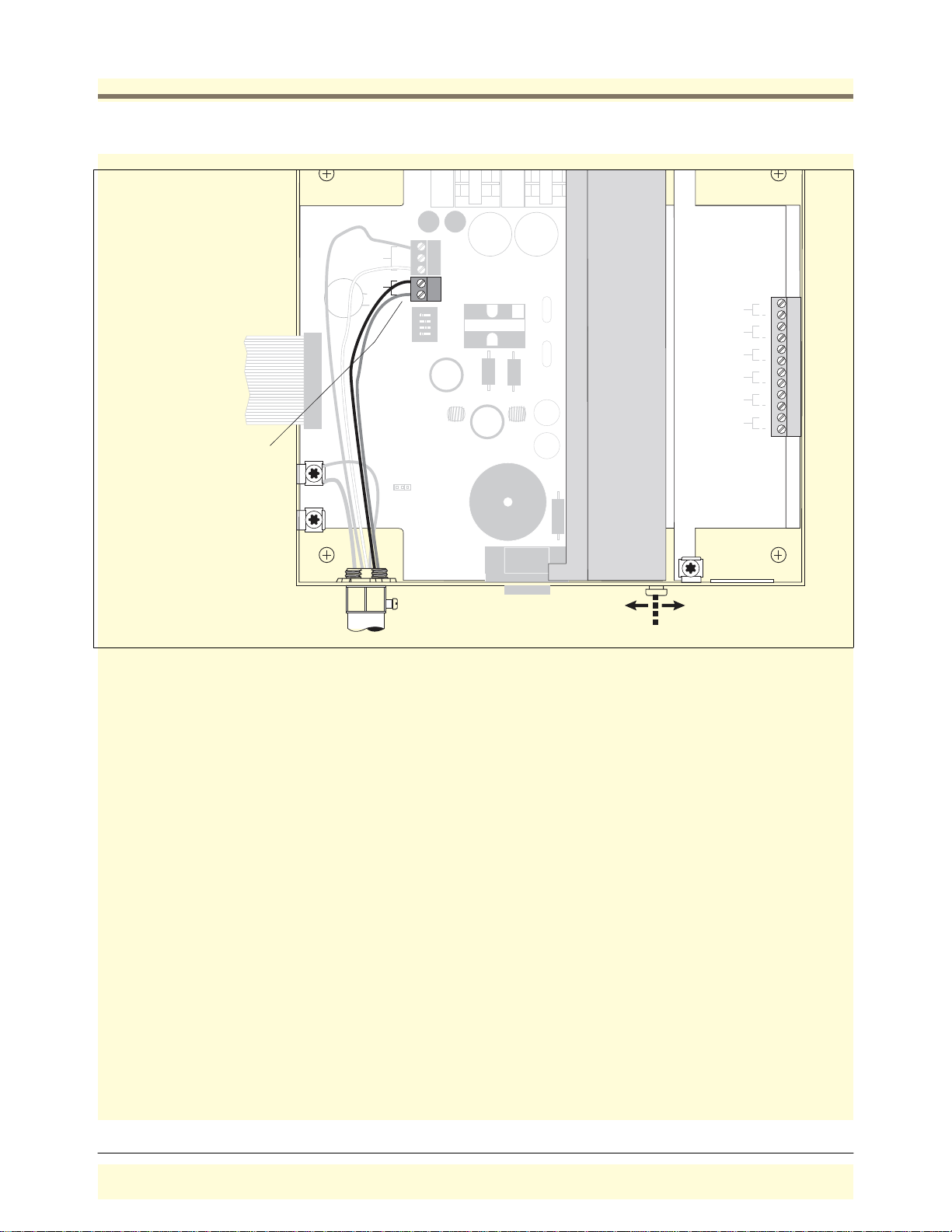
With power to the console turned Off, connect the two wires from the external warning device to the either of the
two overfill relay terminals (J5) [see Figure 17].
18
Page 24
Probe Installation Overfill Alarm Relay
A
t
d
J
WARNING
SUBSTITUTION OF COMPONENTS
CONSOLE
POWER
RELAY RATING
120/240 VAC
2 A MAX
SW1
N
J4
L
J5
1234
OPEN
SEC
SETUP
MAY IMPAIR INTRINSIC SAFETY.
NO REPAIRS SHOULD BE ATTEMPTED.
REFER SERVICING TO QUALIFIED
PERSONNEL ONLY.
PROBE 1
PROBE 2
PROBE 3
PROBE 4
PROBE 5
PROBE 6
+
+
+
+
+
+
ttach the two wires from
he remote overfill warning
evice to the two terminals
5 (no polarity)
J3
AVERTISSEMENT
LA SUBSTITUTION DE COMPOSANTS
PEUT COMPROMETTRE LA SECURITE
INTRINSEQUE.
consoles\tls50\50ovrrly.eps
Power
Side
Intrinsically
Safe Side
Figure 17. Connecting I/O Devices to Console
19
Page 25
Applying Power to System
Cold Boot - Initial Power Up (Consoles w/Display)
Once all devices are connected to the console, attach the console power wires to the appropriate power panel
connections. Close the front panel of the console. Switch on the AC power breaker. The system will automatically
run a cold boot self-diagnostic program when you power up the console for the first time:
Tes t P a ss e d
RAM TEST - OK RAM FAIL Replace CPU board
ROM TEST - OK ROM FA IL “““
COLD BOOT
EEPROM TEST - OK EEPROM FAIL
STARTUP COMPLETE
Following a cold boot the display will read:
NO TANKS CONFIGURED
Follow the Setup instructions in the TLS-50 Setup and Operation Manual to program the system.
Test Failed Action (If Failed)
“““
Cold Boot - Initial Power Up (Consoles w/o Display)
Once all devices are connected to the console, attach the console power wires to the appropriate power panel
connections. Close the front panel of the console. Switch on the AC power breaker. The system will automatically
run a cold boot self-diagnostic program when you power up the console for the first time. Wait 30 seconds and
then follow the Setup instructions in the TLS-50 Setup and Operation Manual to program the system.
Test Failed
Unit fails to communicate Check “RS-232 Serial Communication Setup” on page 24. If comm settings are
correct, replace CPU board.
Action (If Failed)
Cold Boot - RAM Clear
If the system has previously been setup, a cold boot can be initiated and the system reset (such as for a software
upgrade) as follows:
CONSOLES WITH DISPLAY
Move the RAM clear jumper (J3 in Figure 5) off of pins 1 and 2 and onto pins 2 and 3. The display will
acknowledge the RAM clear request with the message: RAM CLEAR, then turn the power Off. Move the jumper
back onto pins 1 and 2.
CONSOLES WITHOUT DISPLAY
Turn off the power to the unit, move the RAM clear jumper (J3 in Figure 5) off of pins 1 and 2 and onto pins 2 and
3. Turn on the power for 5 seconds, then turn the power off. Move the jumper back onto pins 1 and 2.
20
Page 26

Applying Power to System Warm Boot
Warm Boot
CONSOLES WITH DISPLAY
Once the system is setup, every time power to consoles is switched Off and On, the software will run a selfdiagnostic warm boot program and display the test results:
Test Passed
RAM TEST - OK RAM F AIL Replace CPU board
ROM TEST - OK ROM F AI L “““
WARM BOOT
STARTUP COMPLETE
Te s t Fa il e d Action (If Failed)
If a fault is detected an error message will be displayed and the system will halt. When the warm boot completes
the display returns to the top level status message.
CONSOLES WITHOUT DISPLAY
Once the system is setup, every time power to the console is switched Off and On, the software will run a selfdiagnostic warm boot program. Wait 30 seconds and the system should return to normal operation with previous
setups intact.
21
Page 27

RS-232 Communications
The RS-232 port, provided with consoles having form numbers 8469X0-260, -230, and -460, connects to a userselected serial printer, modem or terminal.
RS-232 Peripheral Equipment Requirements
Any peripheral equipment connected to an RS-232 serial port must meet the following criteria:
1. Peripheral equipment must be UL listed.
2. The equipment must have an EIA standard RS-232C or RS-232D communications protocol.
3. The equipment must NOT be installed over or in a hazardous location.
RS-232 Connections
TO A DEVICE LESS THAN 50 FEET FROM THE CONSOLE
Veeder-Root recommends that you use a null-modem cable no longer than 50 feet for direct connections between
the console and a remote device. Cable runs longer than 50 feet can result in data errors, component damage, or
both.
TO A DEVICE MORE THAN 50 FEET FROM THE CONSOLE
If cable runs longer than 50 feet are needed, two short-haul modems should be used, one at the console and one
at the remote device. We recommend an asynchronous short-haul modem, Black Box model ME800A, or
equivalent at the console and at the remote device. For more information, you can contact Black Box by phone:
724-746-5500, Fax: 724-746-0746, or web: http://www.blackbox.com
Figure 18 illustrates how to connect two short-haul modems between the console RS-232 Interface Module’s or
Auxiliary RS-232 Interface Module’s DB-25 connector and the remote device.
22
Page 28
RS-232 Co mmunications Surge P rotection for Communication Devices
Computer
or
consoles\tls50\shmodm.eps
DCE
S1
DTE
DB-9
Connector
To
Available
Port
DB-25
Connector
Color 1
Gnd
TX-
Color 2
TX +
RX-
Color 1
Color 2
RX+
DB-25 Connector
EN
DIS
RTS/DTR
CONTROL
Console
ALL FUNCTIONS NORMAL
T1 VOL: 9889 GAL
TLS-50
DB-9 Connector
2 Twisted Pairs (24 - 26 AWG)
DB-25 Connect
Color 1
Color 2
Color 1
Color 2
DCE
S1
S2
DTE
Gnd
TX-
TX +
RX-
RX+
EN
DIS
RTS/DTR
CONTROL
S2
TD RD
Flash red & green
Black Box Model: ME800A
Loopback
Normal
= Required selection
TD
Flash red & green
RD
Black Box Model: ME800A
Loopback
Normal
Figure 18. Console Connected to a Remote Device via Short-Haul Modem
Surge Protection for Communication Devices
In locations that are subject to high levels of noise and power surges, the use of a surge protector is
recommended. The following models are available from B&B Electronics by phone: 1-815- 433-5100, or web:
http://www.bb-elec.com:
•
Telephone Line Surge Protector, model TLSP
•
RS-232 Surge Protector, model 232DSP
23
Page 29
RS-232 Co mmunications System Serial Securit y
s
System Serial Security
To protect against unauthorized access to system operation DIP switch 1 of SW1 on the Power Supply board lets
you enter a 6-digit security code before the system will respond to a serial command (only applies to consoles
having form numbers 8469X0-260, 230, & -460). If enabled, the default serial security code is 000000. The
security code itself can be changed with a serial command (see “Function Code: 504” on page 31). Consoles are
shipped from the factory with this switch in the open (disabled) position.
See Figure 15 on page 17 for location of this switch. Figure 19 shows the switch in the closed position, enabling
the security feature.
Switch 2 and Switch 3 are not used and can be in any position.
COMM
1234
Sw 1 - Security
OPEN
consoles\tls50\50switch.ep
Figure 19. Console Dip Sw itch Setting s
RS-232 Serial Communication Setup
Table 2 shows the available RS-232 setup options and defaults by console form number.
T able 2.- RS-232 Setup Options and Defaul ts
Setup Options Console Form Numbers Default
Interface mode type Printer, modem, or serial 8469X0-260 Printer
8469X0-230, -460 Serial
Baud rate 300, 600, 1200, 2400, 4800, or 9600 8469X0-260, -460 9600
8469X0-230 2400
Parity None, odd, or Even 8469X0-260, -460 None
8469X0-230 Even
Data length 8 or 7 8469X0-260, -460 8
8469X0-230 7
Stop bits 1 or 2 8469X0-230, -260, -460 1
24
Page 30

RS-232 Co mmunications DB-9 Connector Pin-Outs
Console
or
c
T able 2.- RS-232 Setup Options and Defaul ts
Setup Options Console Form Numbers Default
Handshaking None, XON/XOFF, or hardware 8469X0-260 XON/XOFF
8469X0-230, -460 None
Printer page eject Yes or no 8469X0-260 No
8469X0-230, -460 N/A
Answer on options 0 to 9 8469X0-260 No
8469X0-230, -460 N/A
Serial language English, French, Spanish, or Port uguese 8469X0-230, -260, -460 English
DB-9 Connector Pin-Outs
Communicating with the Console from a remote computer is done through a RS-232 serial port (DB-9 connector)
on the bottom of the console.
Pin layout to connect the Console’s Serial Interface DB-9 connector to a 25-pin computer terminal connector are
shown in Figure 20. These connections are standard for “AT” style modem cables.
(DB-9 Connector)
CD 1 DCD
RXD 2 TXD
TXD 3 RXD
DTR 4 DTR
GND 5 GND
DSR 6 DSR
RTS 7 RTS
CTS 8 CTS
N/C 9 Ring Indicat
onsoles\tls50\\rs-232.eps
Computer Terminal
(DB-25 Connector)
8
2
3
20
7
6
4
5
22
Figure 20. DB9, RS-232 Pin-Outs
25
Page 31

RS-232 Commands
001 System Reset . . . . . . . . . . . . . . . . . . . . . . . . . . . . . . . . . . . . . . . . . . . . . . . . . . . . . . . page 27
003 Remote Alarm Reset . . . . . . . . . . . . . . . . . . . . . . . . . . . . . . . . . . . . . . . . . . . . . . . . . page 28
201 In-Tank Inventory Report. . . . . . . . . . . . . . . . . . . . . . . . . . . . . . . . . . . . . . . . . . . . . . . page 29
205 In-Tank Status Report. . . . . . . . . . . . . . . . . . . . . . . . . . . . . . . . . . . . . . . . . . . . . . . . . page 30
504 Set RS-232 Security Code. . . . . . . . . . . . . . . . . . . . . . . . . . . . . . . . . . . . . . . . . . . . page 31
50C Set Printer Page Eject Enable. . . . . . . . . . . . . . . . . . . . . . . . . . . . . . . . . . . . . . . . . . page 32
50D Set Temperature Compensation Volume Display Enable. . . . . . . . . . . . . . . . . . . . page 33
50E Set Temperature Compensation Value. . . . . . . . . . . . . . . . . . . . . . . . . . . . . . . . . . . page 34
517 Set Units of Measurement and Language (ext. lang. set). . . . . . . . . . . . . . . . . . . . page 35
601 Set Tank Configuration . . . . . . . . . . . . . . . . . . . . . . . . . . . . . . . . . . . . . . . . . . . . . . . page 36
604 Set Tank 1-Point (Full Height) Volume . . . . . . . . . . . . . . . . . . . . . . . . . . . . . . . . . . . page 37
605 Set Tank 4-Point (Full, 3/4, 1/2, & 1/4) Volume. . . . . . . . . . . . . . . . . . . . . . . . . . . . page 38
606 Set Tank 20 Point Full, 95%, 90%,... Volumes . . . . . . . . . . . . . . . . . . . . . . . . . . . . page 39
607 Set Tank Diameter . . . . . . . . . . . . . . . . . . . . . . . . . . . . . . . . . . . . . . . . . . . . . . . . . . . page 40
608 Set Tank Tilt . . . . . . . . . . . . . . . . . . . . . . . . . . . . . . . . . . . . . . . . . . . . . . . . . . . . . . . . page 41
609 Set Tank Thermal Coefficient of Expansion Volume . . . . . . . . . . . . . . . . . . . . . . . . page 42
60A Set Tank Linear Calculated Full Volume . . . . . . . . . . . . . . . . . . . . . . . . . . . . . . . . . . page 43
621 Set Tank Low Level Limit. . . . . . . . . . . . . . . . . . . . . . . . . . . . . . . . . . . . . . . . . . . . . . page 44
624 Set Tank High Water Level Limit. . . . . . . . . . . . . . . . . . . . . . . . . . . . . . . . . . . . . . . . page 45
628 Set Tank Maximum Volume Limit. . . . . . . . . . . . . . . . . . . . . . . . . . . . . . . . . . . . . . . . page 46
638 Set Tank Overfill Limit . . . . . . . . . . . . . . . . . . . . . . . . . . . . . . . . . . . . . . . . . . . . . . . . page 47
881 Set Communication Port Data . . . . . . . . . . . . . . . . . . . . . . . . . . . . . . . . . . . . . . . . . page 48
882 Initialize Communication Port Data. . . . . . . . . . . . . . . . . . . . . . . . . . . . . . . . . . . . . . page 49
883 Set Communication Port Language . . . . . . . . . . . . . . . . . . . . . . . . . . . . . . . . . . . . . page 50
884 Set Serial Port Handshaking. . . . . . . . . . . . . . . . . . . . . . . . . . . . . . . . . . . . . . . . . . . page 51
902 System Revision Level Report . . . . . . . . . . . . . . . . . . . . . . . . . . . . . . . . . . . . . . . . . page 52
A01 Probe Type and Serial Number. . . . . . . . . . . . . . . . . . . . . . . . . . . . . . . . . . . . . . . . . page 53
A02 Probe Calibration Values . . . . . . . . . . . . . . . . . . . . . . . . . . . . . . . . . . . . . . . . . . . . . . page 54
A10 Probe Last Sample Buffers. . . . . . . . . . . . . . . . . . . . . . . . . . . . . . . . . . . . . . . . . . . . page 55
A11 Probe Fast Average Buffers . . . . . . . . . . . . . . . . . . . . . . . . . . . . . . . . . . . . . . . . . . . page 56
A12 Probe Standard Average Buffers . . . . . . . . . . . . . . . . . . . . . . . . . . . . . . . . . . . . . . . page 57
26
Page 32

RS-232 Co mmands Function Code: 001
Function Code: 001
Function Type: System Reset Version 1
Command Format:
Display: <SOH>S00100
Computer: <SOH>s00100
Typical Response Message, Display Format:
<SOH>
S00100
<ETX>
Typical Response Message, Computer Format:
<SOH>s001000000000000&&CCCC<ETX>
Notes:
1. 0000000000 - Not Used.
2. && - Data Termination Flag
3. CCCC - Message Checksum
27
Page 33

RS-232 Co mmands Function Code: 003
Function Code: 003
Function Type: Remote Alarm Reset Version 1
Command Format:
Display: <SOH>S00300
Computer: <SOH>s00300
Typical Response Message, Display Format:
<SOH>
S00300
<ETX>
Typical Response Message, Computer Format:
<SOH>s0030000000000&&CCCC<ETX>
Notes:
1. 0000000000 - Not Used
2. && - Data Termination Flag
3. CCCC - Message Checksum
28
Page 34

RS-232 Co mmands Function Code: 201
Function Code: 201
Function Type: In-Tank Inventory Report
Command Format:
Display: <SOH>I201TT
Computer: <SOH>i201TT
Typical Response Message, Display Format:
<SOH>
I201TT
TANK VOLUME TC VOLUME HEIGHT WATER TEMP
1 5329 5413 48.9 0.0 37.3
<ETX>
Typical Response Message, Computer Format:
<SOH>i201TT0000000000TT0ssssNNFFFFFFFF...
TTpssssNNFFFFFFFF...&&CCCC<ETX>
Version 1
Notes:
1. 0000000000 - Unused
2. TT - Tank Number (Decimal, 00 = all)
3. 0 - Unused
4. ssss - Tank Status Bits:
Bit 1 - (LSB) Unused
Bit 2 - Unused
Bit 3 - Invalid Fuel Height Alarm (MAG Probes Only)
Bit 4-16 - Unused
5. NN - Number of eight character Data Fields to follow (Hex)
6. FFFFFFFF - ASCII Hex IEEE float:
1. Volume
2. TC Volume
3. Ullage
4. Height
5. Water
6. Temperature
7. Water Volume
7. && - Data Termination Flag
8. CCCC - Message Checksum
29
Page 35

RS-232 Co mmands Function Code: 205
Function Code: 205
Function Type: In-Tank Status Report
Command Format:
Display: <SOH>I205TT
Computer: <SOH>i205TT
Typical Response Message, Display Format:
<SOH>
I205TT
TANK STATUS
1 ALL FUNCTIONS NORMAL
<ETX>
Typical Response Message, Computer Format:
<SOH>i205TT0000000000TTnnAA...
TTnnAA&&CCCC<ETX>
Version 1
Notes:
1. 0000000000 - Unused
2. TT - Tank Number (Decimal, 00 = all)
3. nn - Number of alarms active for tank (Hex, 00 = none)
4. AA - Active tank alarm type:
01 = Unused
02 = Unused
03 = Tank High Water Alarm
04 = Tank Overfill Alarm
05 = Tank Low Product Alarm
06 = Unused
07 = Unused
08 = Tank Invalid Height Alarm
09 = Tank Probe Out Alarm
10 = Unused
11 = Unused
12 = Tank Maximum Level Alarm
13 through 26 = Unused
27 = Tank Low Temperature Warning
5. && - Data Termination Flag
6. CCCC - Message Checksum
30
Page 36

RS-232 Co mmands Function Code: 504
Function Code: 504
Function Type: Set System (RS-232) Security Code
Command Format:
Set:
Display: <SOH>S50400aaaaaa Display: <SOH>I50400
Computer: <SOH>s50400aaaaaa Computer: <SOH>i50400
Typical Response Message, Display Format:
<SOH>
I50400
aaaaaa
<ETX>
Typical Response Message, Computer Format:
<SOH>i504000000000000aaaaaa&&CCCC<ETX>
Inquire:
Version 1
Notes:
1. 0000000000 - Not Used.
2. aaaaaa - Current Security Code (6 ASCII characters from 20 Hex - 7E Hex)
3. && - Data Termination Flag
4. CCCC - Message Checksum
31
Page 37

RS-232 Co mmands Function Code: 50C
Function Code: 50C
Function Type: Set Remote Printer Page Eject Flag Version 1
Command Format:
Set:
Display: <SOH>S50C00f Display: <SOH>I50C00
Computer: <SOH>s50C00f Computer: <SOH>i50C00
Typical Response Message, Display Format:
<SOH>
I50C00
f
<ETX>
Typical Response Message, Computer Format:
<SOH>i50C000000000000f&&CCCC<ETX>
Inquire:
Notes:
1. 0000000000 - Not Used
2. f - Page Eject Flag:
0 = Disabled
1 = Enabled
3. && - Data Termination Flag
4. CCCC - Message Checksum
32
Page 38

RS-232 Co mmands Function Code: 50D
Function Code: 50D
Function Type: Set Print Temperature Compensation Flag Version 1
Command Format:
Set:
Display: <SOH>S50D00f Display: <SOH>I50D00
Computer: <SOH>s50D00f Computer: <SOH>i50D00
Typical Response Message, Display Format:
<SOH>
I50D00
f
<ETX>
Typical Response Message, Computer Format:
<SOH>i50D000000000000f&&CCCC<ETX>
Inquire:
Notes:
1. 0000000000 - Not Used
2. f - Print Temperature Compensation Flag
0 = Disable
1 = Enable
3. && - Data Termination Flag
4. CCCC - Message Checksum
33
Page 39

RS-232 Co mmands Function Code: 50E
Function Code: 50E
Function Type: Set Temperature Compensation Value Version 1
Command Format:
Set:
Display: <SOH>S50E00TTT.T Display: <SOH>I50E00
Computer: <SOH>s50E00FFFFFFFF Computer: <SOH>i50E00
Notes:
1. TTT.T - Compensation Temperature, Degrees and tenths (Decimal)
2. FFFFFFFF - Compensation Temperature, Degrees (ASCII Hex IEEE float)
Typical Response Message, Display Format:
<SOH>
I50E00
TTT.T
<ETX>
Inquire:
Typical Response Message, Computer Format:
<SOH>i50E000000000000FFFFFFFF&&CCCC<ETX>
Notes:
1. 0000000000 - Not Used.
2. FFFFFFFF - Compensation Temperature, Degrees (ASCII Hex IEEE float)
3. && - Data Termination Flag
4. CCCC - Message Checksum
34
Page 40

RS-232 Co mmands Function Code: 517
Function Code: 517
Function Type: Set System Type & Language Flags Version 1
Command Format:
Set:
Display: <SOH>S51700ULL Display: <SOH>I51700
Computer: <SOH>s51700ULL Computer: <SOH>i51700
Typical Response Message, Display Format:
<SOH>
I51700
U
LL
<ETX>
Typical Response Message, Computer Format:
<SOH>i517000000000000ULL&&CCCC<ETX>
Inquire:
Notes:
1. 0000000000 - Not Used.
2. U - System Units:
1 = U.S
2 = Metric
3. LL - System Language:
1 = English
2 = French
3 = Spanish
4 = Not Used
5 = Portuguese
6 = Not Used
7 = Not Used
8 = Not Used
9 = Not Used
10 = Not Used
11 = Not Used
12 = Chinese
4. && - Data Termination Flag
5. CCCC - Message Checksum
35
Page 41

RS-232 Co mmands Function Code: 601
Function Code: 601
Function Type: Set Tank Configuration Version 1
Command Format:
Set:
Display: <SOH>S601TTf Display: <SOH>I601TT
Computer: <SOH>s601TTf Computer: <SOH>i601TT
Typical Response Message, Display Format:
<SOH>
I601TT
f
<ETX>
Typical Response Message, Computer Format:
<SOH>i601TT0000000000TTf...
TTf&&CCCC<ETX>
Inquire:
Notes:
1. 0000000000 - Not Used
2. TT - Tank Number (Decimal, 00 = all)
3. f - Tank Configuration Flag:
0 = Off
1 = On
4. && - Data Termination Flag
5. CCCC - Message Checksum
36
Page 42

RS-232 Co mmands Function Code: 604
Function Code: 604
Function Type: Set Tank 1 Point (Full Height Volume) Version 1
Command Format:
Set:
Display: <SOH>S604TTVVVVVV Display: <SOH>I604TT
Computer: <SOH>s604TTFFFFFFFF Computer: <SOH>i604TT
Notes:
1. TT - Tank Number (Decimal, 00 = all)
2. VVVVVV - Full Height Volume, (Decimal)
3. FFFFFFFF - Full Height Volume, (ASCII Hex IEEE float)
Typical Response Message, Display Format:
<SOH>
I604TT
TT P VVVVVV
<ETX>
Inquire:
Typical Response Message, Computer Format:
<SOH>i604TT0000000000TTFFFFFFFF...
TTFFFFFFFF&&CCCC<ETX>
Notes:
1. 0000000000 - Not Used.
2. TT - Tank Number (Decimal, 00 = all)
3. FFFFFFFF - Full Height Volume, (ASCII Hex IEEE float)
5. && - Data Termination Flag
6. CCCC - Message Checksum
37
Page 43

RS-232 Co mmands Function Code: 605
Function Code: 605
Function Type: Set Tank 4-Point (Full, 3/4, 1/2, & 1/4 Height) Volumes Version 1
Command Format:
Set:
Display: <SOH>S605TTGGGGGGggggggGGGGGGgggggg Display: <SOH>I605TT
or: <SOH>S605TTGGGG,gggg,GGGG,ggg
Computer: <SOH>s605TTFFFFFFFFffffffffFFFFFFFFffffffff Computer: <SOH>i605TT
Notes:
1. TT - Tank Number (Decimal, 00 = all)
2. GGGGGG - Full Height Volume, Gallons (Decimal)
3. gggggg - 3/4 Height Volume, Gallons (Decimal)
4. GGGGGG - 1/2 Height Volume, Gallons (Decimal)
5. gggggg - 1/4 Height Volume, Gallons (Decimal)
6. FFFFFFFF - Full Height Volume, Gallons (ASCII Hex IEEE float)
7. ffffffff - 3/4 Height Volume, Gallons (ASCII Hex IEEE float)
8. FFFFFFFF - 1/2 Height Volume, Gallons (ASCII Hex IEEE float)
9. ffffffff - 1/4 Height Volume, Gallons (ASCII Hex IEEE float)
Inquire:
Typical Response Message, Display Format:
<SOH>
I605TT
1 9728 7296 4864 2432
<ETX>
Typical Response Message, Computer Format:
<SOH>i605TT0000000000TTFFFFFFFFffffffffFFFFFFFFffffffff...
TTFFFFFFFFffffffff&&CCCC<ETX>
Notes:
1. 0000000000 - Not Used.
2. TT - Tank Number (Decimal, 00 = all)
3. FFFFFFFF - Full Height Volume, Gallons (ASCII Hex IEEE float)
4. ffffffff - 3/4 Height Volume, Gallons (ASCII Hex IEEE float)
5. FFFFFFFF - 1/2 Height Volume, Gallons (ASCII Hex IEEE float)
6. ffffffff - 1/4 Height Volume, Gallons (ASCII Hex IEEE float)
7. && - Data Termination Flag
8. CCCC - Message Checksum
38
Page 44
RS-232 Co mmands Function Code: 606
Function Code: 606
Function Type: Set Tank 20 Point Full, 95%, 90%,... Volumes Version 1
Command Format:
Set:
Display: <SOH>S606TTGGGGGGggggggGGGGGGgggggg... Display: <SOH>I606TT
or: <SOH>S606TTGGGG,gggg,GGGG,...
Computer: <SOH>
Notes:
1. TT - Tank Number (Decimal, 00=all)
2. GGGGGGgggggg - Series of 20 Volumes, Gallons (Decimal)
3. FFFFFFFF - Series of 20 Volumes, Gallons (ASCII Hex IEEE float)
Typical Response Message, Display Format:
<SOH>
I606TT
JAN 22, 1996 3:16 PM
s606TFFFFFFFF...
Computer: <SOH>i606TT
Inquire:
TANK 20 POINT VOLUMES
TANK PRODUCT LABEL GALLONS
1 REGULAR UNLEADED 9720 9234 8748 8262
7776 7290 6804 6318
5832 5346 4860 4372
3888 3402 2916 2430
1944 1458 972 486
<ETX>
Typical Response Message, Computer Format:
<SOH>i606TT0000000000TTFFFFFFFF...
TTFFFFFFFF&&CCCC<ETX>
Notes:
1. 0000000000 - Not Used.
2. TT - Tank Number (Decimal, 00 = all)
3. FFFFFFFF - Series of 20 Volumes, Gallons (ASCII Hex IEEE float)
4. && - Data Termination Flag
5. CCCC - Message Checksum
39
Page 45

RS-232 Co mmands Function Code: 607
Function Code: 607
Function Type: Set Tank Diameter
Command Format:
Set:
Display: <SOH>S607TTHHH.HH Display: <SOH>I607TT
Computer: <SOH>s607TTFFFFFFFF Computer: <SOH>i607TT
Notes:
1. TT - Tank Number (Decimal, 00 = all)
2. HHH.HH - Tank Diameter (Decimal)
3. FFFFFFFF - Tank Diameter (ASCII Hex IEEE float)
Typical Response Message, Display Format:
<SOH>
I607TT
TT HHH.HH
<ETX>
Inquire:
Version 1
Typical Response Message, Computer Format:
<SOH>i607TT0000000000TTFFFFFFFF...
TTFFFFFFFF&&CCCC<ETX>
Notes:
1. 0000000000 - Not Used.
2. TT - Tank Number (Decimal, 00 = all)
3. FFFFFFFF - Tank Diameter, (ASCII Hex IEEE float)
4. && - Data Termination Flag
5. CCCC - Message Checksum
40
Page 46

RS-232 Co mmands Function Code: 608
Function Code: 608
Function Type: Set Tank Tilt
Command Format:
Set:
Display: <SOH>S608TTHHH.HH Display: <SOH>I608TT
Computer: <SOH>s608TTFFFFFFFF Computer: <SOH>i608TT
Notes:
1. TT - Tank Number (Decimal, 00 = all)
2. HHH.HH - Tank Tilt, (Decimal)
3. FFFFFFFF - Tank Tilt, (ASCII Hex IEEE float)
Typical Response Message, Display Format:
<SOH>
I608TT
TT HHH.HH
<ETX>
Inquire:
Version 1
Typical Response Message, Computer Format:
<SOH>i608TT0000000000TTFFFFFFFF...
TTFFFFFFFF&&CCCC<ETX>
Notes:
1. 0000000000 - Not Used.
2. TT - Tank Number (Decimal, 00 = all)
3. FFFFFFFF - Tank Tilt, (ASCII Hex IEEE float)
4. && - Data Termination Flag
5. CCCC - Message Checksum
41
Page 47

RS-232 Co mmands Function Code: 609
Function Code: 609
Function Type: Set Tank Thermal Expansion Coefficient
Command Format:
Set:
Inquire:
Display: <SOH>S609TTc.cccccc Display: <SOH>I609TT
Computer: <SOH>s609TTFFFFFFFF Computer: <SOH>i609TT
Notes:
1. TT - Tank Number (Decimal, 00 = all)
2. c.cccccc - Thermal Expansion Coefficient (decimal)
3. FFFFFFFF - Thermal Expansion Coefficient (ASCII Hex IEEE float)
Typical Response Message, Display Format:
<SOH>
I609TT
TT c.ccccc
<ETX>
Version 1
Typical Response Message, Computer Format:
<SOH>i609TT0000000000TTFFFFFFFF...
TTFFFFFFFF&&CCCC<ETX>
Notes:
1. 0000000000 - Not Used.
2. TT - Tank Number (Decimal, 00 = all)
3. FFFFFFFF - Thermal Expansion Coefficient (ASCII Hex IEEE float)
4. && - Data Termination Flag
5. CCCC - Message Checksum
42
Page 48

RS-232 Co mmands Function Code: 60A
Function Code: 60A
Function Type: Set Tank Linear Calculated Full Volume
Command Format:
Set:
Display: <SOH>S60ATTVVVVVV Display: <SOH>I60ATT
Computer: <SOH>s60ATTFFFFFFFF Computer: <SOH>i60ATT
Notes:
1. TT - Tank Number (Decimal, 00 = all)
2. VVVVVV - Full Height Volume, (Decimal)
3. FFFFFFFF - Full Height Volume, (ASCII Hex IEEE float)
Typical Response Message, Display Format:
<SOH>
I60ATT
TT P VVVVVV
<ETX>
Inquire:
Version 1
Typical Response Message, Computer Format:
<SOH>i60ATT0000000000TTFFFFFFFF
TTFFFFFFFF&&CCCC<ETX>
Notes:
1. 0000000000 - Not Used.
2. TT - Tank Number (Decimal, 00 = all)
3. FFFFFFFF - Full height volume (ASCII Hex IEEE float)
4. && - Data Termination Flag
5. CCCC - Message Checksum
43
Page 49

RS-232 Co mmands Function Code: 621
Function Code: 621
Function Type: Set Tank Low Level Limit Version 1
Command Format:
Set:
Display: <SOH>S621TTVVVVVV Display: <SOH>I621TT
Computer: <SOH>s621TTFFFFFFFF Computer: <SOH>i621TT
Notes:
1. TT - Tank Number (Decimal, 00 = all)
2. VVVVVV - Low Level Limit, (Decimal)
3. FFFFFFFF - Low Level Limit, (ASCII Hex IEEE float)
Typical Response Message, Display Format:
<SOH>
I621TT
TT VVVVVV
<ETX>
Inquire:
Typical Response Message, Computer Format:
<SOH>i621TT0000000000TTFFFFFFFF...
TTFFFFFFFF&&CCCC<ETX>
Notes:
1. 0000000000 - Not Used.
2. TT - Tank Number (Decimal, 00 = all)
3. FFFFFFFF - Low Level Limit, (ASCII Hex IEEE float)
4. && - Data Termination Flag
5. CCCC - Message Checksum
44
Page 50

RS-232 Co mmands Function Code: 624
Function Code: 624
Function Type: Set Tank High Water Level Limit Version 1
Command Format:
Set:
Display: <SOH>S624TTHH.H Display: <SOH>I624TT
Computer: <SOH>s624TTFFFFFFFF Computer: <SOH>i624TT
Notes:
1. TT - Tank Number (Decimal, 00 = all)
2. HH.H - High Water Level Limit, (Decimal)
3. FFFFFFFF - High Water Level Limit, (ASCII Hex IEEE float)
Typical Response Message, Display Format:
<SOH>
I624TT
TT HH.H
<ETX>
Inquire:
Typical Response Message, Computer Format:
<SOH>i624TT0000000000TTFFFFFFFF...
TTFFFFFFFF&&CCCC<ETX>
Notes:
1. 0000000000 - Not Used.
2. TT - Tank Number (Decimal, 00 = all)
3. FFFFFFFF - High Water Level Limit, (ASCII Hex IEEE float)
4. && - Data Termination Flag
5. CCCC - Message Checksum
45
Page 51
RS-232 Co mmands Function Code: 628
Function Code: 628
Function Type: Set Tank Max Volume Limit Version 1
Command Format:
Set:
Display: <SOH>S628TTVVVVVV Display: <SOH>I628TT
Computer: <SOH>s628TTFFFFFFFF Computer: <SOH>i628TT
Notes:
1. TT - Tank Number (Decimal, 00 = all)
2. VVVVVV - Max Volume Limit, (Decimal)
3. FFFFFFFF - Max Volume Limit, (ASCII Hex IEEE float)
Typical Response Message, Display Format:
<SOH>
I628TT
TT VVVVVV
<ETX>
Inquire:
Typical Response Message, Computer Format:
<SOH>i628TT0000000000TTFFFFFFFF...
TTFFFFFFFF&&CCCC<ETX>
Notes:
1. 0000000000 - Not Used.
2. TT - Tank Number (Decimal, 00 = all)
3. FFFFFFFF - Max Product Limit, (ASCII Hex IEEE float)
4. && - Data Termination Flag
5. CCCC - Message Checksum
46
Page 52

RS-232 Co mmands Function Code: 638
Function Code: 638
Function Type: Set Tank Overfill Level Limit
Command Format:
Set:
Display: <SOH>S638TTDDD Display: <SOH>I638TT
Computer: <SOH>s638TTDDD Computer: <SOH>i638TT
Notes:
1. TT - Tank Number (Decimal, 00 = all)
2. DDD - Overfill Level Limit, (Decimal 0-100%)
Typical Response Message, Display Format:
<SOH>
I638TT
TT DDD
<ETX>
Inquire:
Version 1
Typical Response Message, Computer Format:
<SOH>i638TT0000000000TTDDD...
TTDDD&&CCCC<ETX>
Notes:
1. 0000000000 - Not Used
2. TT - Tank Number (Decimal, 00 = all)
3. DDD - Overfill Level Limit percent, (DECIMAL)
4. && - Data Termination Flag
5. CCCC - Message Checksum
47
Page 53

RS-232 Co mmands Function Code: 881
Function Code: 881
Function Type: Set Communication Port Data Version 1
Command Format:
Set:
Display: <SOH>S881CCBBBBBPSDTAA Display: <SOH>I881CC
Computer: <SOH>s881CCBBBBBPSDTAA Computer: <SOH>i881CC
Typical Response Message, Display Format:
<SOH>
I881CC
CC BBBBB P S D T AA
<ETX>
Typical Response Message, Computer Format:
<SOH>i881CC0000000000CCBBBBBPSD0AA&&CCCC<ETX>
Inquire:
Notes:
1. 0000000000 - Not Used
2. CC - Communication Port Number (1)
3. BBBBB - Baud Rate (Decimal)
4. P - Parity (Decimal; 0=None, 1 or 2)
5. S - Stop Bit (Decimal; 1 or 2)
6. D - Data Bit (Decimal; 7 or 8)
7. 0 - Not Used
8. AA - Number of Rings before Answer (Decimal, 0 - 9)
9. && - Data Termination Flag
10. CCCC - Message Checksum
48
Page 54

RS-232 Co mmands Function Code: 882
Function Code: 882
Function Type: Initialize Communication Port Data Version 1
Command Format:
Set:
Display: <SOH>S882CC149 Display: <SOH>I882CC
Computer: <SOH>s882CC149 Computer: <SOH>i882CC
Notes:
1. 149 - This verification code must be sent to confirm the command
Typical Response Message, Display Format:
<SOH>
I882CC
CC BBBBB P S D T AA
<ETX>
Inquire:
Typical Response Message, Computer Format:
<SOH>i882CC0000000000CCBBBBBPSD0AA&&CCCC<ETX>
Notes:
1. 0000000000 - Not Used.
2. CC - Communication Port Number (1)
3. BBBBB - Baud Rate (Decimal)
4. P - Parity (Decimal; 0= None, 1 or 2)
5. S - Stop Bit (Decimal; 1 or 2)
6. D - Data Bit (Decimal; 7 or 8)
7. 0 - Not Used
8. AA - Number of Rings before Answer (Decimal)
9. && - Data Termination Flag
10. CCCC - Message Checksum
49
Page 55

RS-232 Co mmands Function Code: 883
Function Code: 883
Function Type: Set Serial Communication Language
Command Format:
Set:
Display: <SOH>S88300LL Display: <SOH>I88300
Computer: <SOH>s88300LL Computer: <SOH>i88300
Typical Response Message, Display Format:
<SOH>
I88300
LL
<ETX>
Typical Response Message, Computer Format:
<SOH>i883000000000000LL&&CCCC<ETX>
Inquire:
Version 1
Notes:
1. 0000000000 - Not Used
3. LL - System Language:
1 = English
2 = French
3 = Spanish
4 = Not Used
5 = Portuguese
6 = Not Used
7 = Not Used
8 = Not Used
9 = Not Used
10 = Not Used
11 = Not Used
12 = Not Used
4. && - Data Termination Flag
5. CCCC - Message Checksum
50
Page 56

RS-232 Co mmands Function Code: 884
Function Code: 884
Function Type: Set Serial Handshaking Version 1
Command Format:
Set:
Display: <SOH>S88400f Display: <SOH>I88400
Computer: <SOH>s88400f Computer: <SOH>i88400
Typical Response Message, Display Format:
<SOH>
I88400
f
<ETX>
Typical Response Message, Computer Format:
<SOH>i884000000000000f&&CCCC<ETX>
Inquire:
Notes:
1. 0000000000 - Not Used
2. f - Handshaking method:
0 = Disabled
1 = Hardware
2 = XON/XOFF
3. && - Data Termination Flag
4. CCCC - Message Checksum
51
Page 57

RS-232 Co mmands Function Code: 902
Function Code: 902
Function Type: System Revision Level Report
Command Format:
Display: <SOH>I90200
Computer: <SOH>i90200
Typical Response Message, Display Format:
<SOH>
I90200
SOFTWARE# 349771-vvv-rrr A B
CREATED - YY.MM.DD.HH.mm
<ETX>
Typical Response Message, Computer Format:
<SOH>i902000000000000SOFTWARE# 349771-vvv-rrrCREATED - YY.MM.DD.HH.mm&&CCCC<ETX>
Version 1
Notes:
1. 0000000000 - Not Used
2. vvv - Software version number (ASCII text string)
3. rrr - Software revision level (ASCII text string)
4. YY.MM.DD.HH.mm - Date and time of software creation
5. && - Data Termination Flag
6. CCCC - Message Checksum
7. A = 1 - Alarm Package option installed
8. B = 2 - Serial Package option installed
52
Page 58

RS-232 Co mmands Function Code: A01
Function Code: A01
Function Type: Probe Type and Serial Number
Command Format:
Display: <SOH>IA01TT
Computer: <SOH>iA01TT
Typical Response Message, Display Format:
<SOH>
IA01TT
TT PP KKKK LLLL.LL SSSSSS cccc
<ETX>
Notes:
1. TT - Tank Number (Decimal, 00 = all)
2. PP - Probe Type: - MAG1
3. LLLL.LL - Probe Length (Decimal)
4. SSSSSS - Probe Serial Number (Decimal)
5. cccc - Probe Date Code (Hex)
Version 1
Typical Response Message, Computer Format:
<SOH>iA01TT0000000000TT0PPKKKKFFFFFFFFSSSSSScccc...
TT0PPKKKKFFFFFFFFSSSSSScccc&&CCCC<ETX>
Notes:
1. 0000000000 - Not Used.
2. TT - Tank Number (Decimal, 00 = all)
3. 0 - Not used
4. PP - Probe Type: 03 = MAG1
5. KKKK - Circuit Code (Hex)
6. FFFFFFFF - Probe Length (ASCII Hex IEEE float)
7. SSSSSS - Probe Serial Number (Decimal)
8. cccc - Probe Date Code (Hex)
9. && - Data Termination Flag
10. CCCC - Message Checksum
53
Page 59

RS-232 Co mmands Function Code: A02
Function Code: A02
Function Type: Probe Factory Dry Calibration Values
Command Format:
Display: <SOH>IA02TT
Computer: <SOH>iA02TT
Typical Response Message, Display Format:
<SOH>
IA02TT
TT PP CCC.CCCC
<ETX>
Notes:
1. TT - Tank Number (Decimal, 00 = all)
2. PP - Probe Type: 03 = MAG1
3. CCC.CCCC - Probe Data (Decimal)
Version 1
Typical Response Message, Computer Format:
<SOH>iA02TT0000000000TT0PPNNFFFFFFFF...
TT0PPNNFFFFFFFF...&&CCCC<ETX>
Notes:
1. 0000000000 - Not Used.
2. TT - Tank Number (Decimal, 00 = all)
3. 0 - Not used
4. PP - Probe Type: 03 = MAG1
5. NN - Number of eight character Data Fields to follow (Hex)
6. FFFFFFFF - Calibration Value (ASCII Hex IEEE float)
7. && - Data Termination Flag
8. CCCC - Message Checksum
54
Page 60

RS-232 Co mmands Function Code: A10
Function Code: A10
Function Type: Probe Last Sample Buffers
Command Format:
Display: <SOH>IA10TT
Computer: <SOH>iA10TT
Typical Response Message, Display Format:
<SOH>
IA10TT
TT PP nnnnn
ssss.sss ssss.sss ssss.sss ssss.sss ssss.sss ssss.sss ssss.sss ssss.sss
ssss.sss ssss.sss ssss.sss ssss.sss ssss.sss ssss.sss ssss.sss ssss.sss
ssss.sss ssss.sss ssss.sss ssss.sss ssss.sss ssss.sss ssss.sss ssss.sss
ssss.sss ssss.sss
<ETX>
Version 1
Notes:
1. TT - Tank Number (Decimal, 00 = all)
2. PP - Probe Type:03 - MAG1
3. nnnnn - Sample Number (Decimal)
4. ssss.sss - Probe Data (Decimal)
Typical Response Message, Computer Format:
<SOH>iA10TT0000000000TT0PPSSSSNNFFFFFFFF...
TT0PPSSSSNNFFFFFFFF...&&CCCC<ETX>
Notes:
1. 0000000000 - Not Used
2. TT - Tank Number (Decimal, 00 = all)
3. 0 - Not used
4. PP - Probe Type: 03 - MAG1
5. SSSS - Sample Number (Hex)
6. NN - Number of eight character Data Fields to follow (Hex)
7. FFFFFFFF - Probe Data (ASCII Hex IEEE float)
8. && - Data Termination Flag
9. CCCC - Message Checksum
55
Page 61

RS-232 Co mmands Function Code: A11
Function Code: A11
Function Type: Probe Fast Average Buffers Version 1
Command Format:
Display: <SOH>IA11TT
Computer: <SOH>iA11TT
Typical Response Message, Display Format:
<SOH>
IA11TT
TT PP nnnnn
ssss.sss ssss.sss ssss.sss ssss.sss ssss.sss ssss.sss ssss.sss ssss.sss
ssss.sss ssss.sss ssss.sss ssss.sss ssss.sss ssss.sss ssss.sss ssss.sss
ssss.sss ssss.sss ssss.sss ssss.sss ssss.sss ssss.sss ssss.sss ssss.sss
ssss.sss ssss.sss
<ETX>
Notes:
1. TT - Tank Number (Decimal, 00 = all)
2. PP - Probe Type: 03 - MAG1
3. nnnnn - Sample Number (Decimal)
4. ssss.sss - Probe Data (Decimal)
Typical Response Message, Computer Format:
<SOH>iA11TT0000000000TT0PPSSSSNNFFFFFFFF...
TT0PPSSSSNNFFFFFFFF...&&CCCC<ETX>
Notes:
1. 0000000000 - Not Used
2. TT - Tank Number (Decimal, 00 = all)
3. 0 - Not used
4. PP - Probe Type: 03 - MAG1
5. SSSS - Number of Samples (Hex)
6. NN - Number of eight character Data Fields to follow (Hex)
7. FFFFFFFF - Probe Data (ASCII Hex IEEE float)
8. && - Data Termination Flag
9. CCCC - Message Checksum
56
Page 62

RS-232 Co mmands Function Code: A12
Function Code: A12
Function Type: Probe Standard Average Buffers
Command Format:
Display: <SOH>IA12TT
Computer: <SOH>iA12TT
Typical Response Message, Display Format:
<SOH>
IA12TT
TT PP nnnnn
ssss.sss ssss.sss ssss.sss ssss.sss ssss.sss ssss.sss ssss.sss ssss.sss
ssss.sss ssss.sss ssss.sss ssss.sss ssss.sss ssss.sss ssss.sss ssss.sss
ssss.sss ssss.sss ssss.sss ssss.sss ssss.sss ssss.sss ssss.sss ssss.sss
ssss.sss ssss.sss
<ETX>
Version 1
Notes:
1. TT - Tank Number (Decimal, 00 = all)
2. PP - Probe Type: 03 - MAG1
3. nnnnn - Sample Number (Decimal)
4. ssss.sss - Probe Data (Decimal)
Typical Response Message, Computer Format:
<SOH>iA12TT0000000000TT0PPSSSSNNFFFFFFFF...
TT0PPSSSSNNFFFFFFFF...&&CCCC<ETX>
Notes:
1. 0000000000 - Not Used
2. TT - Tank Number (Decimal, 00 = all)
3. 0 - Not used
4. PP - Probe Type: 03 - MAG1
5. SSSS - Number of Samples (Hex)
6. NN - Number of eight character Data Fields to follow (Hex)
7. FFFFFFFF - Probe Data (ASCII Hex IEEE float)
8. && - Data Termination Flag
9. CCCC - Message Checksum
57
Page 63
Troubleshooting
Print key will be blank on consoles without Serial Package option
consoles\tls50\dkey.eps
This section contains information to help diagnose system problems.
•
Probe troubleshooting
•
CPU/Power board replacement
•
System specifications
•
System compatible probes
Dual-Function Front Panel Keys (consoles w/Keypads Only)
Two of the six front panel keys have dual functions [Figure 21].
1
Back
1
Dual function keys
2
1
SelectEnter
Silent Print
2
Tank
Figure 21. D ual-Functi on Keys
Pressing the Enter key down for an extended period (longer than 2 seconds) will change the system language to
the next available language queued in software. Repeat this procedure until the desired language is displayed.
Pressing the Back key down for at least 2 seconds will change the system setup units Repeat this procedure until
the desired units are displayed.
A short beep from the console beeper will inform the operator that these keys have been held in long enough to
select the alternate function. When the operator is ready to return to the originally programmed language and/or
units, switch the console power off and then back on. The system will perform a warm boot and return to the
originally programmed language and units.
Probe Troubleshooting
CONSOLES W/O DISPLAY
Probe troubleshooting can be performed using the appropriate RS-232 serial commands (see appropriate section
in this manual).
CONSOLES W/DISPLAY
The Diagnostic Menu is accessed from the front panel of the console. From the Top Level menu press the Select
key until the display reads DIAGNOSTICS, then follow the key presses shown in Figure 22. Figure 23 contains an
general explanation of the diagnostic displays.
58
Page 64
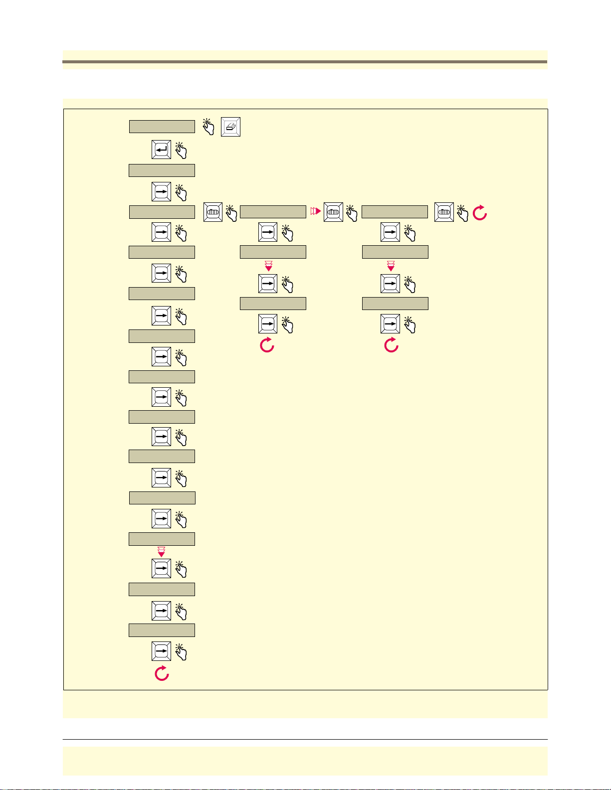
Troubleshooting Probe Troubleshooting
DIAGNOSTICS
PRESS <ENTER>
SOFTWARE VERSION
XXXXXX-XXX Y
T1: PROBE TYPE:
GLB01
T1: SERIAL NUMBER
XXXXX
T1: PROBE ID
0XD011
T1: PROBE LENGTH
96.0
T1: GRADIENT
0180.0000
Prints out the Diagnostic Report if your console has the Serial Package option,
you have made the correct communication setup selections, and you have
a serial printer connected.
T2: PROBE TYPE:
GLB01
T1: SERIAL NUMBER
XXXXXX
T2: COUNTS
18 XXXXX
T6: PROBE TYPE:
GLB01
T6: SERIAL NUMBER
XXXXXX
T6: COUNTS
18 XXXXX
T1: NUMBER SAMPLES
20
T1: SAMPLES READ
XXXXXX
T1: SAMPLES USED
XXXXXX
T1: COUNTS
00 XXXXX 01 XXXXX
T1: COUNTS
16 XXXXX 17 XXXXX
T1: COUNTS
18 XXXXX
consoles\tls50\50diag.eps
Figure 22. Diagnostic Menu - Overview
59
Page 65
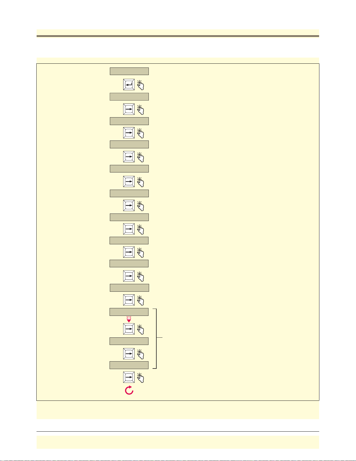
Troubleshooting Probe Troubleshooting
t
DIAGNOSTICS
PRESS <ENTER>
SOFTWARE VERSION
XXXXXX-XXX Y
T1: PROBE TYPE:
GLB01
T1: SERIAL NUMBER
XXXXX
T1: PROBE ID
0XD011
T1: PROBE LENGTH
XXX
T1: GRADIENT
XXX.XXXX
T1: NUMBER SAMPLES
20
T1: SAMPLES READ
XXXXXX
Console's current software version: XXXXXX-XXX
Options: Y= 1 Alarm package, Y= 2 Serial and Alarm Package).
Probe's serial number.
Probe's manufacturing code.
Probe calibration factor used to calculate water height and product height.
Number of probe measurement sets made before posting water height,
product volume, and product temperature. (A measurement set consists of
probe counts 00 - 18 discussed below.)
Historical total of probe measurements read.
T1: SAMPLES USED
XXXXXX
T1: COUNTS
00 XXXXX 01 XXXXX
T1: COUNTS
16 XXXXX 17 XXXXX
T1: COUNTS
18 XXXXX
Historical total of probe measurements used.
Probe counts used to calculate water height, product volume, and
product temperature. Counts 00 - 18 constitute one probe measuremen
set.
consoles\tls50\50dgex.eps
Figure 23. Diagnostic Menu - Explanation
60
Page 66
Troubleshooting Replacing the CPU Board
Probe Diagnostic Report
The Diagnostic Report example below is a printout of probe information, for all tanks. The probe functions are
discussed in Figure 23.
DIAGNOSTICS
SOFTWARE VERSION 349771-001-A
TANK : 1 2 3
PROBE TYPE : GLB8 GLB8 GLB8
SERIAL NUMBER : 123001 123002 123003
PROBE ID : D021 D021 D021
PROBE LENGTH : 96.0 96.0 96.0
GRADIENT : 350.00 350.00 350.00
NUMBER SAMPLES : 20 20 20
SAMPLES READ : xxxxxx xxxxxx xxxxxx
SAMPLES USED : xxxxxx xxxxxx xxxxxx
COUNTS 00 : xxxxx xxxxx xxxxx
01 : xxxxx xxxxx xxxxx
02 : xxxxx xxxxx xxxxx
03 : xxxxx xxxxx xxxxx
04 : xxxxx xxxxx xxxxx
05 : xxxxx xxxxx xxxxx
06 : xxxxx xxxxx xxxxx
07 : xxxxx xxxxx xxxxx
08 : xxxxx xxxxx xxxxx
09 : xxxxx xxxxx xxxxx
10 : xxxxx xxxxx xxxxx
11 : xxxxx xxxxx xxxxx
12 : xxxxx xxxxx xxxxx
13 : xxxxx xxxxx xxxxx
14 : xxxxx xxxxx xxxxx
14 : xxxxx xxxxx xxxxx
15 : xxxxx xxxxx xxxxx
16 : xxxxx xxxxx xxxxx
17 : xxxxx xxxxx xxxxx
18 : xxxxx xxxxx xxxxx
Replacing the CPU Board
The CPU board in the console must be replaced when:
•
A system self-test failure occurs during a warm or cold boot, or
•
The display (on certain models) contains garbled messages and/or the voltage between the GND and 8V test
points on the back of the CPU board is within 7 - 9 Vdc; or,
•
The voltage between the GND and 5V test points [Figure 24] on the back of the CPU board is not within 4.75 -
5.25 Vdc.
OFF
1. Turn Off power to the system.
61
Page 67

Troubleshooting Replacing the CPU Board
C
S
ps
HANDLING THIS BOARD!
5V
able to Power
upply Board
GND 8V
LED1
J1
These voltage test points are on the back of
the CPU board (directly behind this upper left
corner)
+
PROM chip
C5
STATIC SENSITIVE - WEAR
GROUNDED ANIT-STATIC
WRIST STRAP BEFORE
U5
Figure 24. CPU Board Voltage Test Points (Keypad/Display version shown)
Y2
TLS-50 CPU
consoles\tls50\cpu.e
2. Attach the anti-static strap to your wrist and to a good ground.
3. Disconnect the CPU cable from the Power Supply board.
4. The CPU board snaps securely into place in the door of the console without the use of screws. There are two
tabs on the top of the board that fit into two slots in the top edge of the door. The bottom of the CPU board
snaps in place between two pairs of detents protruding from the bottom edge of the door. The CPU board is
removed by inserting a straight-slot screwdriver into one of the two indents on the bottom of the board and
then gently prying against the door until the board clears the upper detents, then rotating the board up slightly
and toward you to clear the top tabs from the slots in the door.
5. Replace the CPU board reversing the above steps.
6. Follow the cold boot instructions beginning on page 20.
62
Page 68

Troubleshooting PROM Chip Replacement (Software Upgrade)
PROM Chip Replacement (Software Upgrade)
The PROM chip is replaced when a software upgrade is installed. This procedure requires that you perform a
RAM clear.
1. If possible, record the current setup information. Turn off power to the system.
OFF
2. Open the front door of the console. The CPU board is installed in the door.
3. Attach anti-static strap to your wrist and to a good ground.
4. Disconnect the CPU board cable from the Power Supply board. Remove the CPU board following the
instructions in “Replacing the CPU Board” on page 61.
5. Locate the PROM chip on the board [Figure 24].
6. Remove the PROM chip following instructions in Figure 25.
7. Replace the PROM chip following instructions in Figure 26.
8. Replace the CPU board in the front door of the TLS-50. Connect the CPU board cable to J1 on the Power
Supply board.
9. Follow the cold boot instructions for your console type beginning on page 20.
63
Page 69
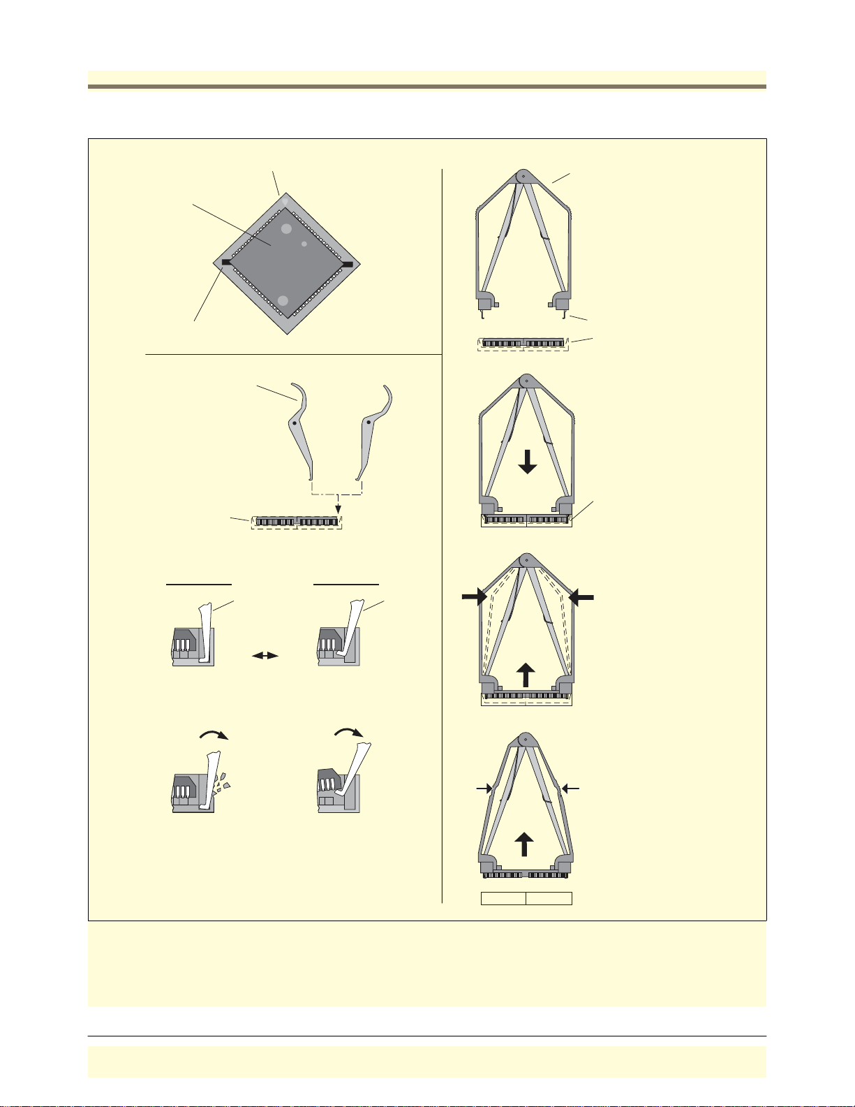
Troubleshooting PROM Chip Replacement (Software Upgrade)
D,
C
(
Chip socket
Removable
chip
Chip removal slots
hip Removal Tool
Chip Removal Tool
(Digikey Part No. K293-N
or equivalent)
Lifting hooks
Chip socket
P/N 576036-022)
Incorrect
Angle
Correct
Angle
lifting hooks
go down in
slots and under
chip until tool
rests on socket
Chip socket
INCORRECT
ANGLE
Tool Tool
Cutaway of
chip in socket
CORRECT
ANGLE
As you squeeze
the sides of the
removal tool with
your hand, the
hooks will lift the
chip out of the
Hook down too
far and rests in
Hook in correct
position under chip
socket.
socket indent
When you rotate
tool, you will crack
the chip socket.
consoles\h8remov1.eps
Lift up chip when
it is free from
socket.
When you rotate tool,
you will lift the corner
of the chip out of the
socket (alternate
between two chip
removal slots)
Figure 25. Removing PROM Chip
64
Page 70

Troubleshooting PROM Chip Replacement (Software Upgrade)
C
S
5V
able to Power
upply Board
GND 8V
LED1
These voltage test points are on the back of
the CPU board (directly behind this upper left
corner))
J1
PROM chip
socket
consoles\tls50\50cpurm.eps
+
C5
U5
Y2
1) Orient PROM so that the small indented dot on
top of the chip is on the same side with the small
triangle embossed in the socket's base; or,
2) If the chip is covered with a label you can also orient
STATIC SENSITIVE - WEAR
GROUNDED ANIT-STATIC
WRIST STRAP BEFORE
HANDLING THIS BOARD!
the chip correctly if you insert the chip in the socket
with its angled corner in the same angled corner of the
socket.
3) Carefully align the chip's pins with the socket's pins.
(If you have the pins aligned correctly, the chip will seem to
drop into the socket.) Then push down firmly and evenly
on the chip until it snaps into the socket.
4) Check to see that all pins are in place and none are bent.
Figure 26. Replacing PROM Chip (Keypad/Display version shown)
65
Page 71
Troubleshooting Replacing the Power Supply Board
Replacing the Power Supply Board
The Power Supply board must be replaced when:
•
Probe data is not being processed, or
•
The voltage between the GND and 8V test points [Figure 24] on the back of the CPU board is less than 7 Vdc.
OFF
1. Turn Off power to the system.
2. Disconnect the CPU cable from the Power Supply board.
3. Tag and disconnect probe, power, and overfill alarm relay wiring to the Power Supply board.
4. The Power Supply board is secured by two T-15 Torx screws in the top of the board. For consoles with the com
option (see Table 1 on page 1), the two screw locks which go through the bottom of the console into the DB-9
connector must also be removed before you can lift out the board.
After removing the Torx screws (and screw locks), slowly lift up on the board until the lower tabs on the board
clear the slots in the bottom of the console, then continue to lift the board out.
5. Replace the board by reversing the above steps.
6. Turn on power to the system. The system will perform a warm boot procedure [page 21] and the display will
return to the top level status screen. You do not have to reprogram the console after replacing the Power
Supply board.
66
Page 72

Console Specifications
PHYSICAL SPECIFICATIONS
•
Width (door closed): 7.6”, open 9.6”) Depth (door closed 2.6”, open 9”))
•
Height: 6.7” Weight: 3.5 lbs.
•
Two PC boards in console: CPU (in door) and Power Supply (in unit)
ENVIRONMENTAL SPECIFICATIONS
•
Console storage and operation: indoor, climate controlled.
ELECTRICAL SPECIFICATIONS
•
Console operating voltage: 120/240 Vac, 2 A max.
•
The Power Supply board fuses F1 and F2 are NOT field replaceable The rating for both fuses is 2 A, Type T
[Time Lag].
SIGNAL INPUT SPECIFICATIONS
•
Up to 6 probes monitored with TLS-50, or 3 probes monitored with TLS-50C
•
Probe data: 0.15 A at 12 volts
SIGNAL OUTPUT SPECIFICATIONS
•
One dry contact Relay Output: 120 Vac, 2 A
FRONT PANEL USER INTERFACE (CONSOLES W/DISPLAY)
•
Two line, graphic LCD display
•
Visible annunciator (bi-color LED)
Green - all functions normal
Flashing red - alarm active
•
Push keys
Select
Enter
Print (optional)
Back
Silence
Tan k
•
Audible annunciator: internal beeper
67
Page 73
Console Specifications Probe Circuit Codes
Probe Circuit Codes
Table 2 lists the probes that can be used with various TLS-50 Console Form Nos. Probe Form Nos. 8990 are only
compatible with Console Form Nos. 846910-XXX.
T able 2.- Probe Cir cuit Codes
Circuit
Code Probe Form
D021 846891-199 GLB8 --- Gasoline Yes 2
D021 846891-299 GLB8 --- Diesel Yes 2
D021 846891-399 GLB8 --- Light Oil Yes 2
D022 846891-499 GLB9 --- Gasoline No 2
D022 846891-599 GLB9 --- Diesel No 2
D022 846891-699 GLB9 --- Light Oil No 2
D023 846891-799 GLB10 --- None Yes 1
D024 846891-899 GLB11 --- None No 1
D026 899021-2XX Mag Plus 0.2 GPH - Gasoline --- Y es 2
D026 899031-2XX Mag Plus 0.2 GPH - Diesel --- Yes 2
D027 899021-3XX Mag Plus Inv. Only - Gasoline --- Yes 2
D027 899031-3XX Mag Plus Inv. Only - Diesel --- Yes 2
All 8990 probes are Nepsi appr oved. The standard configuration for an 8990 probe is stainless steel with a 5foot (1. 524 m ) cable.
Probe
Type Probe Description
Water
Float Type
Temperature
Measurement
No. of
Floats
68
Page 74

Appendix A: TLS-50 and TLS-50C Safety Instructions
1. Refer to Veeder-Root Descriptive System Document 331940-003 for system installation requirements. This drawing
can be found on the Veeder-Root Tech Docs CD-ROM shipped with your console.
2. Refer to the site preparation procedures in this manual for general instructions on safe installation, use, and
replacement.
3. The TLS-50 and TLS-50C systems do not require periodic maintenance or calibration.
4. The TLS-50 and TLS-50C systems are serviceable. If a failure occurs, the unit should be repaired in accordance with
the requirements in the Troubleshooting section of this manual. Note: There are no replaceable components within
the encapsulated protective circuits. If a protective circuit fails, it must be replaced in its entirety.
A-1
Page 75

Page 76

For technical support, sales or
other assistance, please visit:
www.veeder.com
 Loading...