

Page 1

Manual No: 577013-934 ● Revision: E
Site Prep Certification Manual
TLS-450/TLS-450PLUS Consoles
Page 2

Notice
Veeder-Root makes no warranty of any kind with regard to this publication, including, but not limited to, the implied warranties of
merchantability and fitness for a particular purpose.
Veeder-Root shall not be liable for errors contained herein or for incidental or consequential damages in connection with the furnishing,
performance, or use of this publication.
Veeder-Root reserves the right to change system options or features, or the information contained in this publication.
This publication contains proprietary information which is protected by copyright. All rights reserved. No part of this publication may be
photocopied, reproduced, or translated to another language without the prior written consent of Veeder-Root.
Contact TLS Systems Technical Support for additional troubleshooting information at 800-323-1799.
DAMAGE CLAIMS / LOST EQUIPMENT
Thoroughly examine all components and units as soon as they are received. If any cartons are damaged or missing, write a complete
and detailed description of the damage or shortage on the face of the freight bill. The carrier's agent must verify the inspection and sign
the description. Refuse only the damaged product, not the entire shipment.
Veeder-Root must be notified of any damages and/or shortages within 30 days of receipt of the shipment, as stated in our Terms and
Conditions.
VEEDER-ROOT’S PREFERRED CARRIER
1. Contact Veeder-Root Customer Service at 800-873-3313 with the specific part numbers and quantities that were missing or
received damaged.
2. Fax signed Bill of Lading (BOL) to Veeder-Root Customer Service at 800-234-5350.
3. Veeder-Root will file the claim with the carrier and replace the damaged/missing product at no charge to the customer. Customer
Service will work with production facility to have the replacement product shipped as soon as possible.
CUSTOMER’S PREFERRED CARRIER
1. It is the customer’s responsibility to file a claim with their carrier.
2. Customer may submit a replacement purchase order. Customer is responsible for all charges and freight associated with
replacement order. Customer Service will work with production facility to have the replacement product shipped as soon as
possible.
3. If “lost” equipment is delivered at a later date and is not needed, Veeder-Root will allow a Return to Stock without a restocking fee.
4. Veeder-Root will NOT be responsible for any compensation when a customer chooses their own carrier.
RETURN SHIPPING
For the parts return procedure, please follow the appropriate instructions in the "General Returned Goods Policy” pages in the
"Policies and Literature" section of the Veeder-Root North American Environmental Products price list. Veeder-Root will not accept
any return product without a Return Goods Authorization (RGA) number clearly printed on the outside of the package.
©Veeder-Root 2014. All rights reserved
.
ii
Page 3

Table of Contents
Introduction
Related Documents ..........................................................................................................1
Documents Required to Install Equipment ...............................................................1
Safety Precautions ............................................................................................................1
National Electrical Code Compliance ................................................................................2
Probe- and Sensor-to-Console Wiring......................................................................2
Power Wiring ............................................................................................................2
Console Installation
Locating the Console ........................................................................................................3
Mounting the Console .......................................................................................................3
Wiring the Console ...........................................................................................................5
Special Mag Probe Installation Kits
AST Installation Kit ...........................................................................................................6
Vapor Extraction Riser Kit W/ Coupling Adapter ...............................................................7
Vapor Extraction Riser Kit W/O Coupling Adapter ............................................................8
Riser Cap Kit for Mag Probe Installations .........................................................................9
Cap and Cord Grip Kit ..............................................................................................9
Metal Cap and Ring Kit.............................................................................................9
Mag Probe Installation
UST/AST Tank - Dedicated Riser ...................................................................................11
UST Riser Cap Attachment ....................................................................................11
AST Riser Cap Attachment ....................................................................................13
UST Installation - Vapor Extractor Riser W/ Coupling Adapter .......................................13
UST Installation - Vapor Extractor Riser W/O Coupling Adapter ....................................15
Probe and Sensor Conduit Installation
Wiring Run Methods .......................................................................................................17
Buried Rigid Conduit...............................................................................................17
Direct Burial Cable..................................................................................................18
Wiring Module Bay Devices
I/O Module Wiring ...........................................................................................................19
MDIM Module Wiring ......................................................................................................20
LVDIM Module Wiring .....................................................................................................21
iii
Page 4

Figures
Table of Contents
Figure 1. TLS-450/TLS-450PLUS Consoles Dimensions and
Designated Conduit Knockouts ..............................................................4
Figure 2. Wiring AC Power to the TLS-450/TLS-450PLUS Consoles ...................5
Figure 3. Mag Probe AST Installation Kit ...............................................................6
Figure 4. Mag Probe vapor extractor w/coupling adapter installation kit ...............7
Figure 5. Mag Probe vapor extractor w/o coupling adapter installation kit ............8
Figure 6. Cap and Cord Grip Kit ............................................................................9
Figure 7. Metal Cap and Ring Kit .........................................................................10
Figure 8. Modifying an existing metal riser cap ....................................................10
Figure 9. UST probe installation - dedicated riser ................................................11
Figure 10. AST probe installation - dedicated riser ................................................12
Figure 11. Installing a riser adapter beneath the metal cap and adapter ring ...........12
Figure 12. Vapor extractor cabling entry ................................................................13
Figure 13. Mag probe vapor extractor riser installation - w/ coupling adapter...........15
Figure 14. Mag probe vapor extractor riser installation - w/o coupling adapter.........16
Figure 15. Example Probe Wiring Run in Buried Rigid Conduit .............................17
Figure 16. Example Probe Wiring Run via Direct Burial Cable ..............................18
Figure 17. I/O Relay Module Connections .............................................................19
Figure 18. MDIM Module Pulser Connections .......................................................20
Figure 19. LVDIM Module POS/Pulser Connections .............................................21
Tables
Table 1. Mag Probe AST Installation Kit - Part No. 312020-984 .............................6
Table 2. Vapor Extraction Riser Kit (w/ coupling adapter)
- Part No. 846500-001 ...............................................................................7
Table 3. Vapor Extraction Riser Kit (W/O Coupling Adapter)
- Part No. 846500-002 ...............................................................................8
Table 4.- Cap and cord grip kit - Part No. 330020-282 .............................................9
Table 5.- Metal cap and ring kit - Part No. 312020-952 ............................................9
iv
Page 5
Introduction
OFF
This manual assumes that you are installing the console in a new site (before pavement is put down and with no
wiring runs in place). Among the topics covered are:
• Site layout considerations.
• Installing the console and connecting wiring from the AC power panel.
• Probe installation procedures.
• Sensor installation procedures.
• Installing wiring conduit between the console and the probes and sensors.
• Probe and sensor field junction box wiring diagrams.
• Attaching sensor wiring to the console.
Related Documents
DOCUMENTS REQUIRED TO INSTALL EQUIPMENT
This equipment must be installed according to the applicable installation document:
Equipment
ATEX
Descriptive System
Document No. Document No. Document No.
IECEx
Descriptive System
UL/cUL
Control Drawing
Associated Apparatus
TLS-450/TLS-450PLUS 331940-006 331940-106 331940-008
Intrinsically Safe Apparatus for Wireless Applications
Tank Gauge Accessories 331940-005 331940-105 331940-012
Safety Precautions
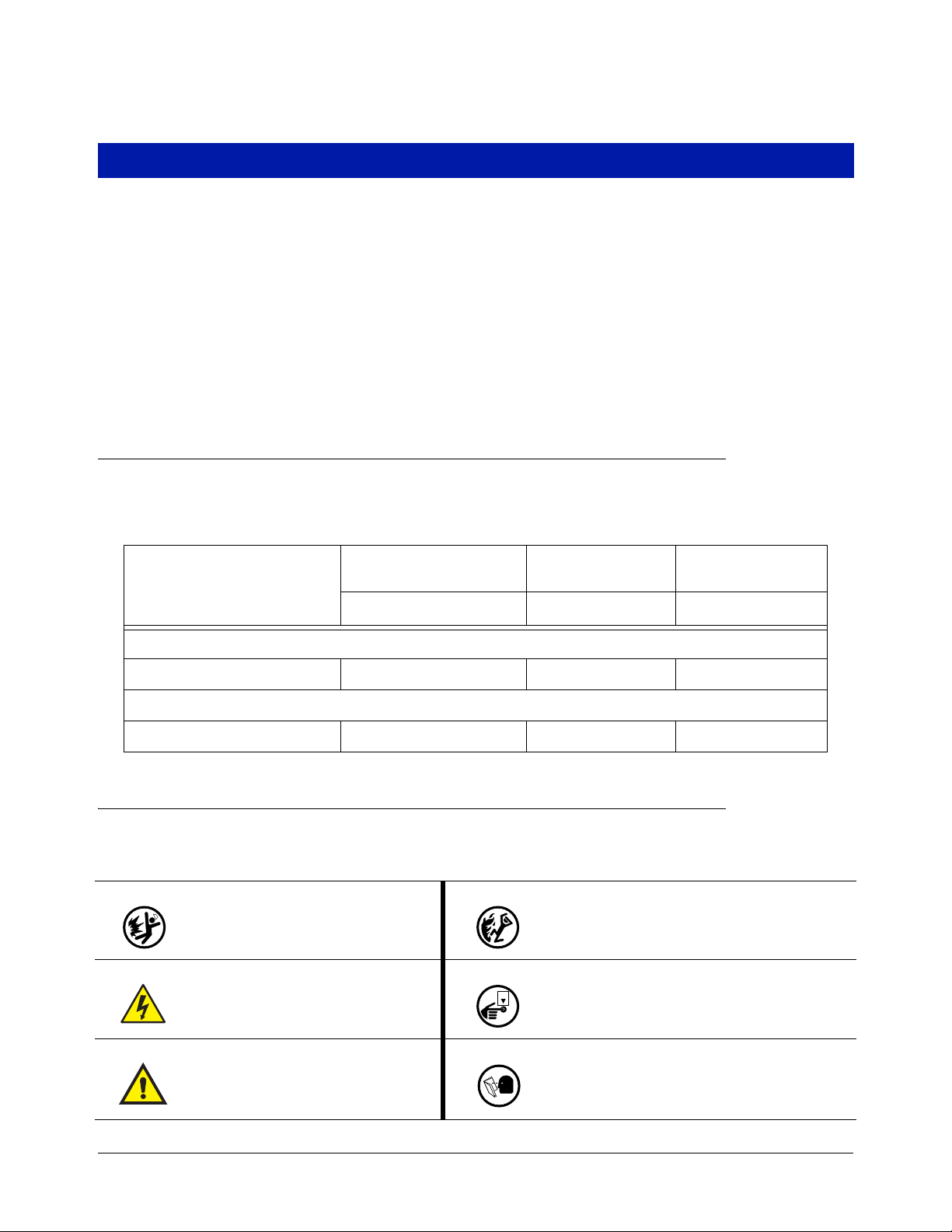
The following safety symbols may be used throughout this manual to alert you to important safety hazards and
precautions.
EXPLOSIVE
Fuels and their vapors are extremely
explosive if ignited.
ELECTRICITY
High voltage exists in, and is supplied to,
the device. A potential shock hazard
exists.
FLAMMABLE
Fuels and their vapors are extremely flammable.
TURN ELECTICAL POWER OFF
Live power to a device creates a potential shock
hazard. Turn Off electrical power to the device and
associated accessories when servicing the unit.
WAR N ING
Heed the adjacent instructions to avoid
damage to equipment, property, environment or personal injury.
1
READ ALL RELATED MANUALS
Knowledge of all related procedures before you
begin work is important. Read and understand all
manuals thoroughly. If you do not understand a procedure, ask someone who does.
Page 6

Introduction National Electrical Code Compliance
National Electrical Code Compliance
The following information is for general reference and is not intended to replace recommended National Electric
Code (NEC) procedures. It is important for the installer to understand that electrical equipment and wiring located
in Class I, Division 1 and 2 installations shall comply with the latest appropriate Articles found in the National
Electric Code (NFPA 70), the Automotive and Marine Service Station Code (NFPA 30A), CEC codes and all
applicable local codes.
PROBE- AND SENSOR-TO-CONSOLE WIRING
Wire Type
To ensure the best operating systems available, Veeder-Root REQUIRES the use of shielded cable for all probes
and sensors regardless of conduit material or application. In these installations, shielded cable must be rated less
than 100 picofarad per foot and be manufactured with a material suitable for the environment, such as Carol™
C2534 or Belden™ 88760, 8760, 8770 or similar.
Note: Throughout this manual, when mentioning any cable or wire being used for probe and sensor to console
wiring, it will be referring to shielded cable.
Wire Length
Improper system operation could result in undetected potential environmental and health hazards if the probe- or
sensor-to-console wire runs exceed 1000 feet. Wire runs must be less than 1000 feet to meet intrinsic safety
requirements.
Wire Gauges - Color coded
Shielded cable must be used in all installations. Sensor-to-console wires should be #14-#18 AWG stranded
copper wire and installed as Class 2 circuits. As an alternate method when approved by the local authority having
jurisdiction, #22 AWG wire such as Belden 88761 may be suitable in installations with the following provisions:
• Wire run is less than 750 feet
• Capacitance does not exceed 100 pF/foot
• Inductance does not exceed 0.2 H/foot
POWER WIRING
Wires carrying 120 or 240 Vac from the power panel to the console should be #14 AWG (or larger) copper wire
for line, neutral and chassis ground (3); and #12 AWG copper wire for barrier ground.
2
Page 7
Console Installation
Locating the Console
WARNI NG
FAILURE TO COMPLY WITH THE FOLLOWING WARNINGS AND SAFETY
PRECAUTIONS COULD CAUSE DAMAGE TO PROPERTY, ENVIRONMENT,
RESULTING IN SERIOUS INJURY OR DEATH.
Explosive vapors or flammable liquids could be present near locations where
fuels are stored or being dispensed.
This console is not explosion proof. Do not install this console in a volatile,
combustible, or explosive atmosphere.
An explosion or fire resulting in serious injury or death, property loss and
equipment damage could occur if the console is installed in a volatile,
combustible or explosive atmosphere (Class I, Division 1 or 2).
Select a mounting location on the inside of any building. The console must be protected from severe vibration,
extremes in temperature and humidity, rain, and other conditions that could harm computerized electronic
equipment. The console’s operating temperature range is 32 to 104°F (0 to 40°C), and its storage temperature
range is -40 to +162°F (-40 to +74°C).
The mounting surface should be strong enough to support the console’s weight which could be approximately 35
pounds with a full complement of modules. You should also consider wall space for routing the power wiring
conduits and probe and sensor wiring conduits that must be connected to the console.
Mounting the Console
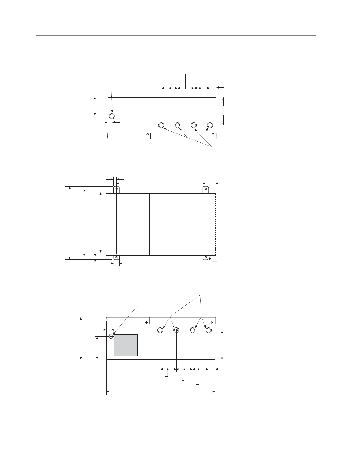
Install the console fastening devices to the mounting surface using the hole pattern shown in Figure 1. Up to 1/4”
diameter screws may be used.
Mount the console to the mounting surface using the four mounting flanges on the back of the unit. Install metal
conduit between the console and the power panel. Figure 1 shows the two designated knockouts through which
power wiring can safely enter the console.
3
Page 8
Console Installation Mounting the Console
Conduit entry for
console power
3/4, 1 I.P.S. knockouts
4-5/8''
0.65''
1/2'' TYP.
11''13''
12''
3-1/8''
3-1/8''
3-1/8''
1"
5.925''
Conduit entries to Module bay
TOP VIEW
3/4, 1 I.P.S. knockouts
(typ. 4 places)
16'' 1-1/8" Typ.
1/2'' TYP.
1'' TYP.
Mounting flanges w/ 1/4'' x 3/8''
slotted hole - typ 4 places
FRONT VIEW
Conduit entry for console power
0.540", 1/2 I.P.S. knockouts
Conduit entries to Module bay
3/4, 1 I.P.S. knockouts
(typ. 4 places)
0.65''
8-7/8''
4-5/8''
3-1/8''
3-1/8''
3-1/8''
5.925''
1-7/16''
18.35''
BOTTOM VIEW
Figure 1. TLS-450/TLS-450PLUS Consoles Dimensions and Designated Conduit Knockouts
tlsng\dim.eps
4
Page 9
Console Installation Wiring the Console
OFF
L1
N
L2
L1
G
L2
(To 240 Vac
breaker in
power panel)
240 Vac Power Input 120 Vac Power Input
L1 (BLK)
N/L2 (WHT)
N/L2 (BLK)
G (GRN)
Barrier (G/Y)
L1 (RED)
(To 120 Vac
breaker in
power panel)
Attach barrier wire
to grounding clamp
Power connector
conduit entry
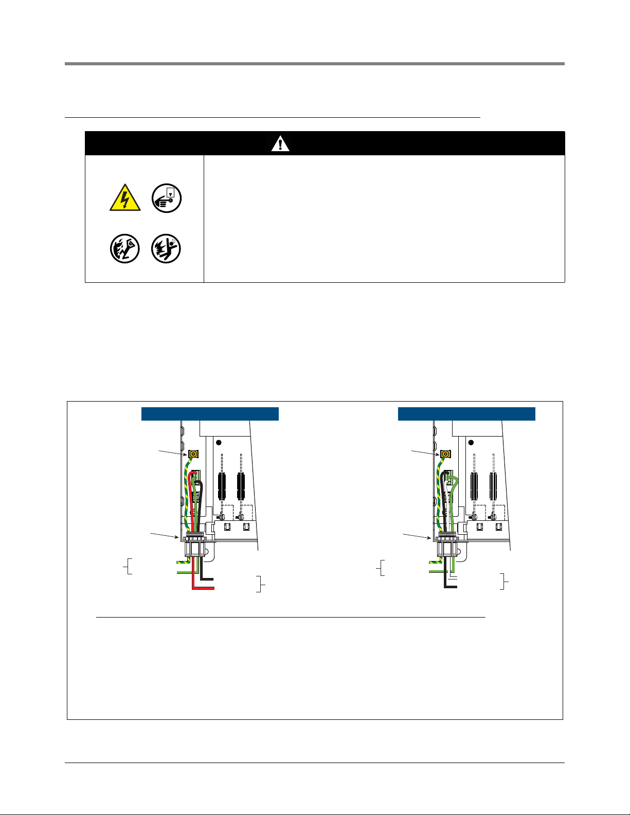
• Barrier ground wire requirements:
- For UL/cUL approved systems, use a 12 AWG barrier ground wire
- For ATEX/IECEx approved systems, use a 4 sq. mm barrier ground wire
• Use an ohmmeter to check the electrical resistance between the console’s metal case and the power panel’s earthing
ground wire connection at the ‘known good ground’. It should read less than 1 ohm.
• Connect the power supply wires in the power panel to a separate dedicated circuit.
• Electrical rating of power input - 120 or 240 Vac, 50/60 Hz, 2 A maximum.
• See Figure 1 for locations of power conduit knockouts into the console. Power wiring must enter the console
through designated knockouts.
POWER WIRING NOTES:
To grounding
terminal bar
in power panel
G (GRN)
Barrier (G/Y)
To grounding
terminal bar
in power panel
Attach barrier wire
to grounding clamp
Power connector
conduit entry
Wiring the Console
WARNI NG
This console contains high voltages which can be lethal. It is also connected
to low power devices that must be kept intrinsically safe.
1. Do not connect the console AC power supply wires at the breaker until
all devices are installed.
2. Attach conduit from the power panel to the console's Power Area
knockouts only.
Connecting power wires to a live circuit can cause electrical shock that may
result in serious injury or death.
Routing conduit for power wires into the intrinsically safe compartment can
result in fire or explosion resulting in serious injury or death.
1. Check the Input Power Rating on the label affixed to the underside of the console to verify whether input
power requirements are 120 Vac or 240 Vac.
2. Pull three #14 AWG or larger color-coded wires for AC line (hot), AC neutral and chassis ground between the
power panel and the console.
3. Pull one wire, with a minimum 90°C rating, for barrier ground - For UL/cUL installations use a # 12 AWG wire;
For ATEX/IECEx installations use a 4 mm
4. Connect the input 120 or 240 Vac power wires as shown in Figure 2.
2
wire.
Figure 2. Wiring AC Power To The TLS-450/TLS-450PLUS Consoles
5
Page 10
Special Mag Probe Installation Kits
Locking nut
J-box
O-ring
Body
fitting
Ferrule
Nut
Nut
Ferrule
Body
fitting
O-ring
Adapter Nut
(Connects to riser cap)
3/8'' Flexible Conduit
3/8'' Liquidtight Connector Assembly
At Riser Cap
3/8'' Liquidtight Connector Assembly
At J-Box
(Plastic coated 5-foot
length, 0.72 '' OD x 0.42'' ID)
probes/astkit.eps
Cord Grip Fitting
Body
Cord Grip
Nut
Note: watch orientation
of bevels and tapers
when assembling these
cord grip components.
Bushing
In addition to the Mag Probe installation kits shipped with each probe (containing floats, spacer rings, cable, etc.),
your installation may also require one or more of the special kits described in this section.
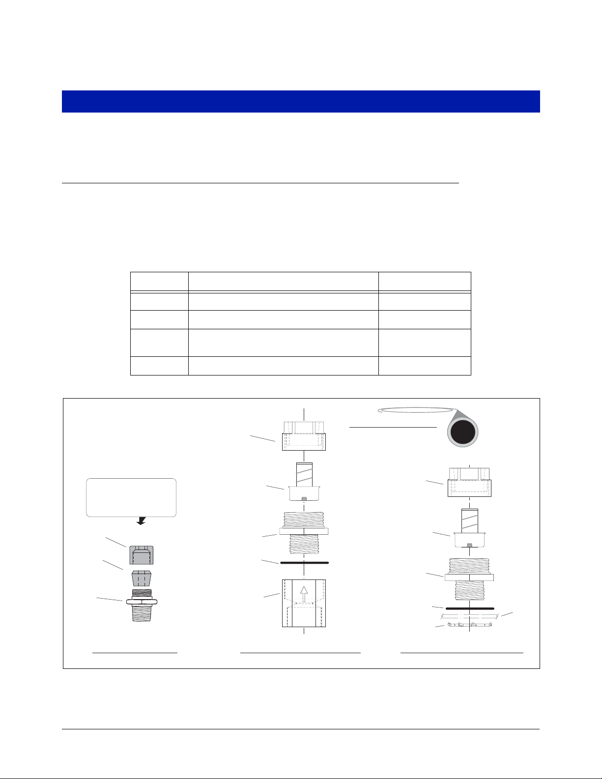
AST Installation Kit
This kit is recommended when installing Mag Probes into an above ground storage tank (AST). This kit contains a
length of flexible conduit, connectors, etc., for easier probe access. The kit contents are listed in Table 1 and
shown in Figure 3.
Table 1. Mag Probe AST Installation Kit - Part No. 312020-984
Quantity Description Part Number
5 feet 3/8” Flexible Conduit 576008-294
1 3/8” Adapter Nut 329972-002
2
Related Parts 576008-295
1 Cord Grip Group 331028-001
3/8” Straight Liquidtite Connectors And
Figure 3. Mag Probe AST Installation Kit
6
Page 11
Special Mag Probe Installation Kits Vapor Extraction Riser Kit W/ Coupling Adapter
probes\vapradpt.eps
1/4 NPT tapped hole
for cord grip fitting
Modified OPW
Adaptor
Fitting - PG7 / 1/4" NPT Cord Grip
Shield - Fitting
4" Hose Clamp
12 Inches Flexible Conduit
Splice Enclosure
Cable Tie
Wire Nuts
O-ring
Threaded Fitting
Nylon Splined Bushing
Dome Nut
This end
screws
into OPW
Adaptor
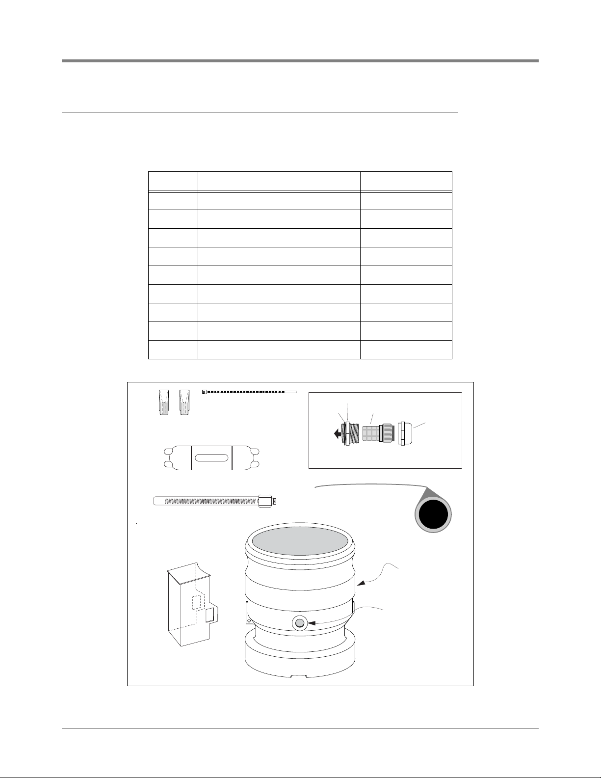
Vapor Extraction Riser Kit W/ Coupling Adapter
This kit contains parts needed to install a Mag Probe into a Vapor Extractor Riser that has a Coupling Adapter
(parts listed in Table 2 and shown in Figure 4):
Table 2. Vapor Extraction Riser Kit (w/ coupling adapter) - Part No. 846500-001
Quantity Description Part Number
2 Wire Nut 576008-461
1 Cable Tie 576008-482
1 Splice Enclosure 514100-357
1 Splice Kit Instructions Manual 576013-861
1 PG7 / 1/4” Cord Grip Fitting 576008-637
1 Modified OPW Adapter 331448-001
1 Shield -Fitting 331449-001
1 4” Hose Clamp 576008-638
12 inches Flex Conduit 576008-294
Figure 4. Mag Probe Vapor Extractor W/coupling Adapter Installation Kit
7
Page 12
Special Mag Probe Installation Kits Vapor Extraction Riser Kit W/O Coupling Adapter
probes\nonvapr.eps
12 Inches Flexible Conduit
Splice Enclosure
4" NPT Riser Cap and Gasket
Cord Grip Bushing
Cord Grip Nut
Cable Tie
Wire Nuts
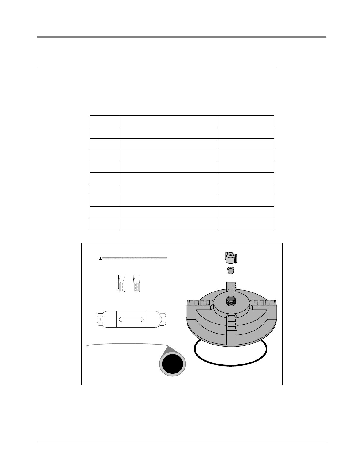
Vapor Extraction Riser Kit W/O Coupling Adapter
This kit contains parts needed to install a probe in a Vapor Extractor Riser that does not have a coupling adapter
(parts listed in Table 3 and shown in Figure 5):
Table 3. Vapor Extraction Riser Kit (W/O Coupling Adapter) - Part No. 846500-002
Quantity Description Part Number
2 Wire Nut 576008-461
1 Cable Tie 576008-482
1 Splice Enclosure 514100-357
1 Splice Kit Instruction Manual 576013-861
1 Riser Cap 331106-001
1 Gasket 331140-001
1 Cord Grip Bushing 330787-001
1 Cord Grip Nut 330594-001
12 inches Flex Conduit 576008-294
Figure 5. Mag Probe Vapor Extractor W/O Coupling Adapter Installation Kit
8
Page 13
Special Mag Probe Installation Kits Riser Cap Kit for Mag Probe Installations
probes\risrcap.eps
4" NPT Riser Cap and Gasket
Cord Grip Bushing
Cord Grip Nut
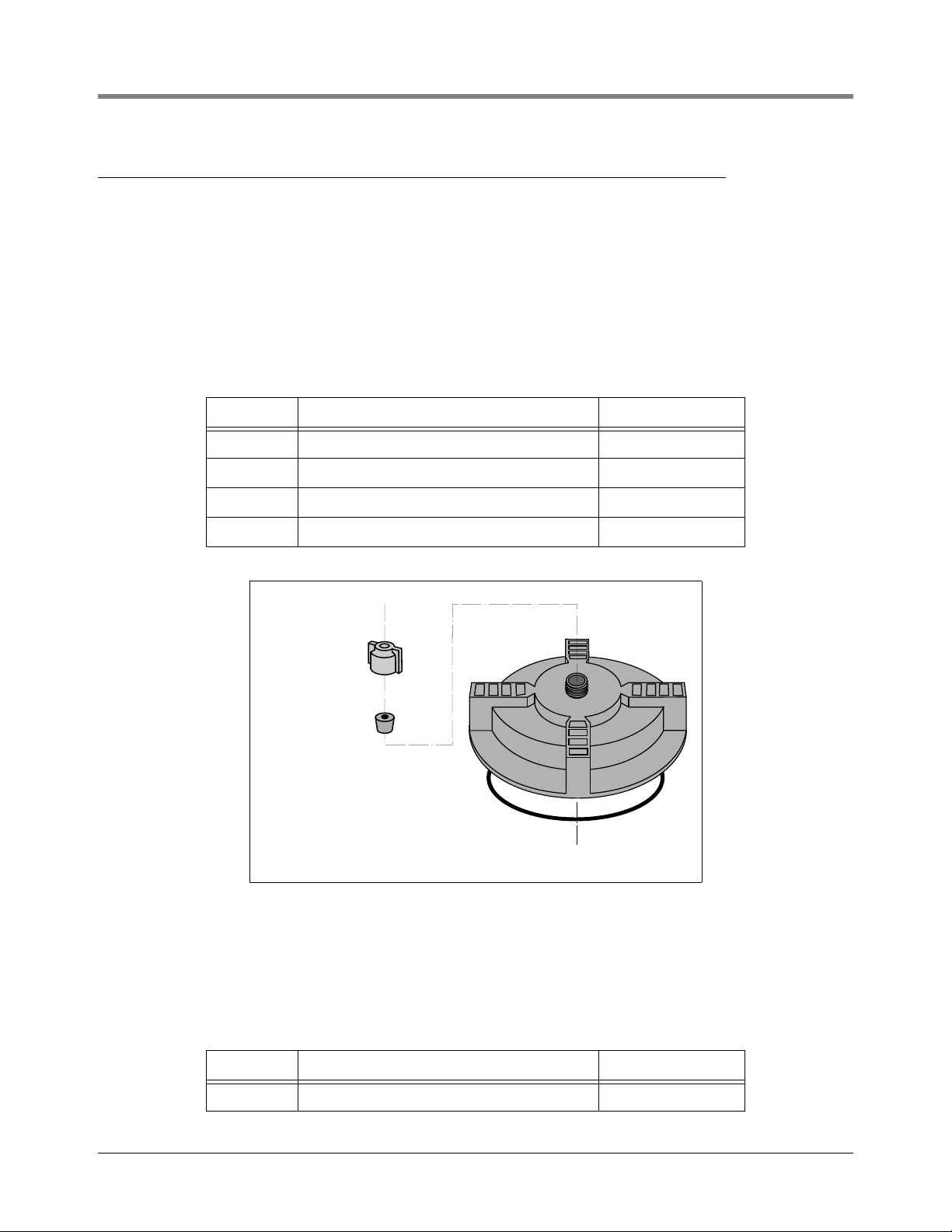
Riser Cap Kit for Mag Probe Installations
The cap on the riser containing the Mag Probe must be modified to allow the probe’s cable to exit the riser. This
modification requires making a 1/2”-14 NPT tapped hole in the cap for a cord grip. Two types of drilled and
tapped Riser Cap kits are available for purchase, or you may be able to modify the existing riser cap.
CAP AND CORD GRIP KIT
This Riser Cap kit (Table 4) contains a non-metallic cap which screws onto the 4” NPT riser (Figure 6). The cap
comes drilled and tapped with a cord grip.
Table 4.- Cap and cord grip kit - Part No. 330020-282
Quantity Description Part Number
1 Cap Riser 331106-001
1 Gasket 331140-001
1 Bushing - Cord Grip 330787-001
1 Nut - Cord Grip 330594-001
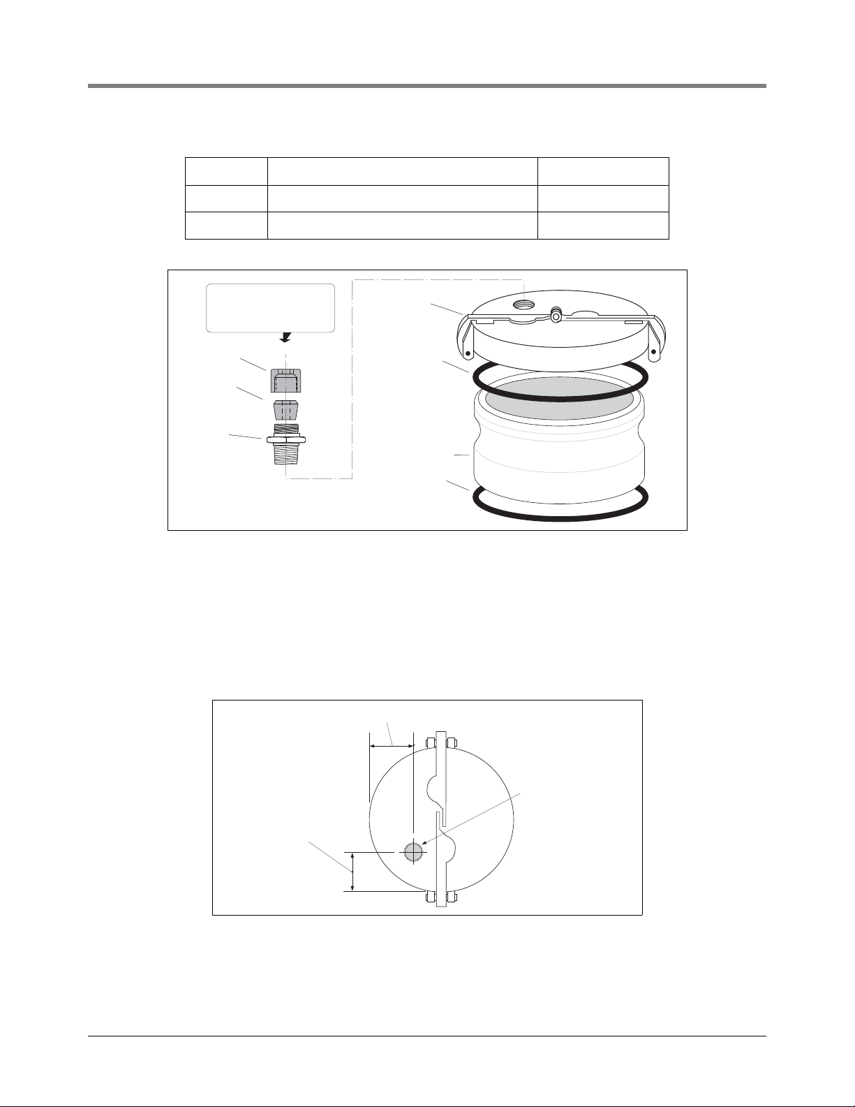
Figure 6. Cap And Cord Grip Kit
METAL CAP AND RING KIT
This riser cap kit contains an adapter ring which screws onto the 4”NPT riser and a quick-release metal cap which
clamps onto the ring (Table 5). The cap comes drilled and tapped with a cord grip (Figure 7).
Table 5.- Metal cap and ring kit - Part No. 312020-952
Quantity Description Part Number
1 Adapter Ring And Gasket 514100-332
9
Page 14
Special Mag Probe Installation Kits Riser Cap Kit for Mag Probe Installations
1.438 ±0.062 (36.53 ±1.6)
1.625 ±0.062 (41.27 ±1.6)
1/2" - 14 NPT hole
probes\prbricp.eps
Table 5.- Metal cap and ring kit - Part No. 312020-952
Quantity Description Part Number
1 Cap And Gasket 327869-003
1 Group Cord Grip 331028-001
Note: watch orientation
of bevels and tapers
when assembling these
cord grip components.
Cord Grip
Nut
Bushing
Body
Cord Grip Fitting
Metal cap
w/1/2" NPT
tapped hole
Cap gasket
Adapter ring
Ring gasket
probes\cap&ring.eps
Figure 7. Metal Cap And Ring Kit
Modifying an Existing Metal Cap
In order to ensure that the riser cap seals properly to the probe cable and riser, we recommend that you purchase
one of the kits available for this purpose. Riser Caps from other manufacturers may require modification. If you use
your own metal riser cap, you must drill and tap it for a cord grip fitting (P/N 331028-001) as follows.
1. Remove the cap to a non-hazardous location.
2. Drill and tap the cap for a 1/2”-14 NPT cord grip thread [Figure 8].
Figure 8. Modifying An Existing Metal Riser Cap
10
Page 15
Mag Probe Installation
OFF
.
.
.
.
.
..
.
.
.
.
.
.
.
.
.
.
.
.
..
.
.
.
.
.
.
.
Riser cap with cord grip
bushing and nut
Concrete slab or packed
earth per NFPA 80
Riser pipe: 2-, 3-, or 4'' API schedule 40
depending on probe type
Cord grip seals
Weatherproof junction box with 1/2" NPT
threads (16 cubic inch minimum)
14'' min. dia. manhole
Seal-off, epoxy seal per NFPA spec
Mag Probe
(rests on bottom)
Tank
A = 10" minimum for global mag
plus/mag plus
probes. When
installing a probe longer than the
the tank diameter, increase this
minimum dimension to compensate.
(Example: a 7'-6'' diameter tank will
use an 8' probe, in which case you
must add 6" to minimum riser length
'A').
1/2" Rigid conduit (to Console)
Probe cable
A
Split-Ring Collar
(P/N 576008-617)
required if probe
enters the riser.
Top view
Side view
3/4" ID
UST/AST Tank - Dedicated Riser
1. Turn OFF power to the console.
2. Remove any sludge from the bottom of the tank.
3. Check that floats, boot, and cable are assembled correctly on probe (ref. Mag Probe Assembly Manual).
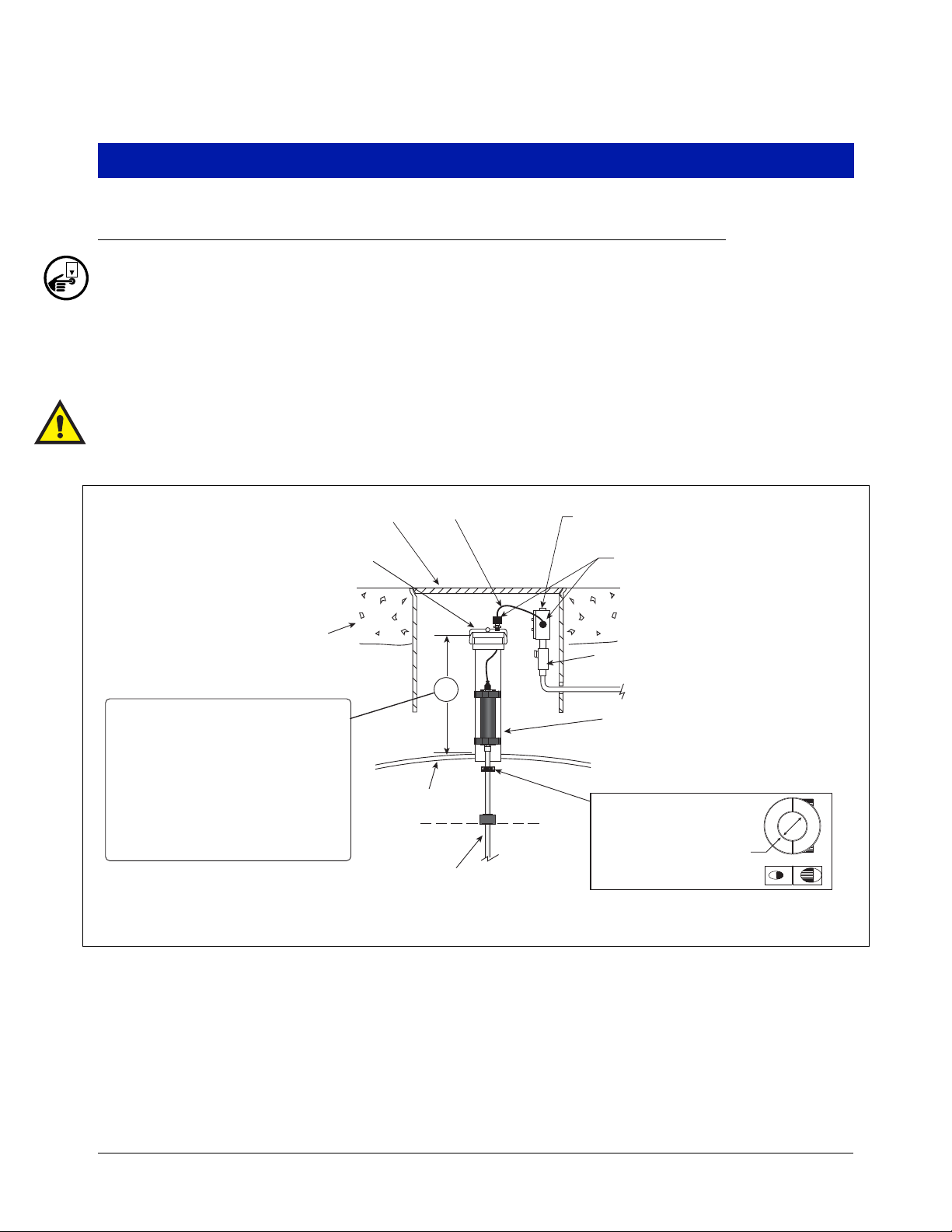
4. Gently slide the float(s) to the bottom of the probe shaft before raising the probe. Carefully lower the probe
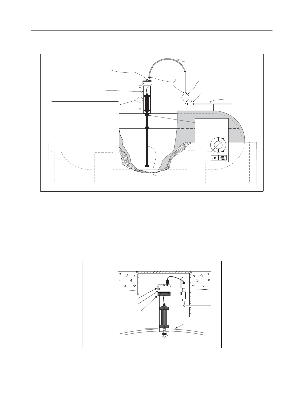
into the riser pipe until the boot rests on the bottom of the tank [See Figure 9 for UST installation or Figure 10
for AST installation].
WARNING! Handle probes carefully. Striking or dropping the probe will result in loss of calibration and damage to the probe.
UST RISER CAP ATTACHMENT
1. If you are using the one piece cap (see Figure 6 on page 9), push the end of the probe cable through the cord
grip bushing and nut on the cap, leaving a minimal amount of slack between the probe and cap. Screw the
cap onto the riser by hand until the gasket first contacts the pipe. Then lightly tap the cap with a hammer to
tighten it an additional 3/4 turn. Go to Step 3.
Figure 9. UST Probe Installation - Dedicated Riser
11
Page 16
Mag Probe Installation UST/AST Tank - Dedicated Riser
Use bushing and body of grip
fitting supplied with probe and
Adaptor nut supplied with
AST kit.
Epoxy seal per NFPA specs
Flexible metal conduit
supplied with AST kit
Weatherproof junction box with
1/2" NPT threads (16 cubic inch
minimum)
Rigid conduit
Liquidtight
fittings from
AST kit
Mag Probe
(rests on bottom)
probes\astpbins.eps
Riser pipe: 2-, 3-, or 4'' API
schedule 40 - depending on
probe type
A
A = 10" minimum for global mag
plus/mag plus probes. When
installing a probe longer than the
the tank diameter, increase this
minimum dimension to compensate.
(Example: a 7'-6'' diameter tank will
use an 8' probe, in which case you
must add 6" to minimum riser length
'A', i.e., 16").
Split-Ring Collar
(P/N 576008-617)
required if probe
enters the riser.
Top view
Side view
3/4" ID
2. If you are installing the metal cap and adapter ring (see Figure 7 on page 10), screw the ring onto the 4” riser
until the gasket contacts the pipe, then use a pipe wrench to tighten it an additional 3/4 turn. Push the cable
through the metal cap and cord grip, then clamp the cap onto the ring.
At sites that require installation of a riser adapter (Phil-Tite M/F 4X4 or equivalent) at the top of the riser, do so
following the manufacturer’s instructions. Next screw the adapter ring from the Veeder-Root kit (
952) onto the riser adapter by hand until the gasket contacts the sealing surface. Then use a torque wrench attached to an appropriate strap wrench (K-D Specialty tools nylon strap oil filter wrench, or equivalent) and tighten the ring to 35 - 45 ft-lbs. Loosen the cord grip nut and push the cable through the metal cap and cord grip,
then clamp the cap onto the ring (see Figure 11).
Figure 10. AST Probe Installation - Dedicated Riser
.
.
.
.
..
Metal cap from kit
Adapter ring from kit
.
.
.
.
.
.
.
.
.
.
.
.
.
.
.
.
.
.
.
.
..
Riser adapter
(Phil-Tite M/F4X4,
or equivalent)
Figure 11. Installing A Riser Adapter Beneath The Metal Cap And Adapter Ring
Tank
P/N 312020-
12
Page 17
Mag Probe Installation UST Installation - Vapor Extractor Riser W/ Coupling Adapter
4" Riser
probes\verprep.eps
Manhole Cover
(Backfill)
(Concrete)
Flex Conduit
Sawcut trench for
Direct Burial Cable
Jackhammered entry to
bottom of manhole
3. Make sure there is a minimal amount of slack between the probe and cap, then tighten the cord grip nut until
the cable is held firmly. Push the end of the cable through the field J-box cord grip, then tighten that cord grip
nut as well. Splice and seal the wires in the J-box.
AST RISER CAP ATTACHMENT
1. If you are using the one piece cap (see Figure 6 on page 9), push the end of the probe cable through the cap
and cord grip bushing, leaving a minimal amount of slack between the probe and cap. Discard the cord grip
nut and attach the adapter Nut from the AST kit to the cap (see Figure 3 on page 6). Tighten the adapter Nut
until the cable is held firmly. Go to Step 3.
2. If you are installing the metal cap and ring (see Figure 7 on page 10), screw the ring onto the 4” riser until the
gasket contacts the pipe, then use a pipe wrench to tighten it an additional 3/4 turn. Using UL-classified pipe
sealant (suitable for the fuels involved), screw the cord grip fitting into the tapped hole and tighten. Place the
cord grip bushing in the fitting. Discard the cord grip nut and loosely screw the adapter Nut from the AST kit
onto the cord grip fitting (see Figure 3 on page 6). Push the cable through the metal cap, bushing, and
adapter nut, then clamp the cap onto the ring. Make sure there is a minimal amount of slack between the
probe and cap, then tighten the adapter Nut until the cable is held firmly.
3. Next assemble the liquidtight connectors on both ends of the flexible conduit as shown in Figure 3. Push the
cable through the flexible conduit assembly and into the J-box. Connect the flexible conduit assembly to the
adapter Nut on one end and the J-box on the other.
4. Tighten the fittings until snug. Splice and seal the wires in the J-box.
UST Installation - Vapor Extractor Riser W/ Coupling Adapter
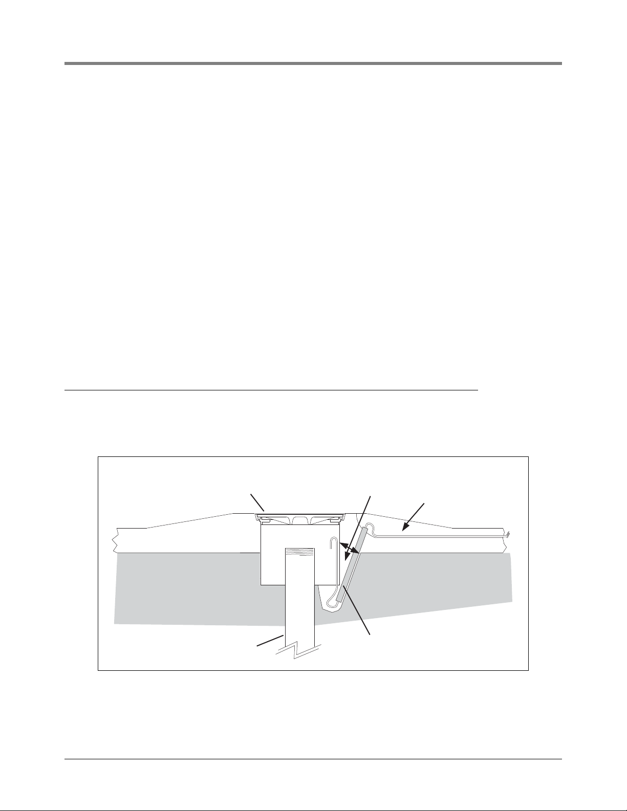
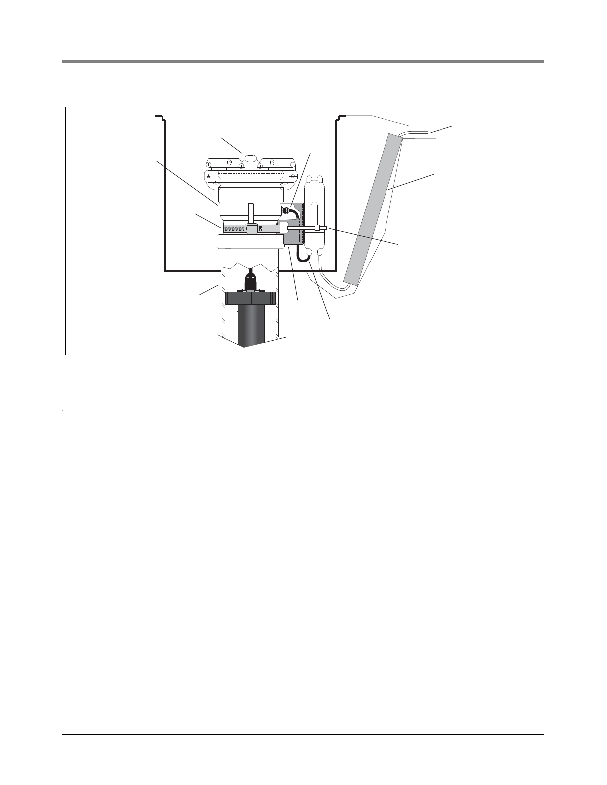
This type installation is usually a retrofit and is usually connected to the console via direct burial cabling. The site
should already be prepped (all digging, saw cutting, and jackhammering done) prior to probe installation (see
Figure 12). A piece of flex conduit should be in place as shown to protect the cable.
Figure 12. Vapor Extractor Cabling Entry
1. Remove any existing hardware from the Vapor Extractor Riser so that it’s 4” NPT riser threads are exposed.
13
Page 18

Mag Probe Installation UST Installation - Vapor Extractor Riser W/ Coupling Adapter
2. Use the extractor wrench tool (OPW Part Number: 89-0044) to remove the Ball Float Check Valve and
Extractor Cage inside the bottom of the 4” riser. Important! - Ball Float Check Valve and Extractor Cage may
be difficult to remove; use caution.
3. Remove any sludge from the bottom of the tank.
4. Assemble the probe floats, spacer rings, and cable as per the Mag Probe Assembly Manual.
5. Gently slide the float(s) to the bottom of the probe shaft. Important! - Handle probes carefully. Striking or
dropping the probe will result in loss of calibration and could cause permanent damage.
6. Carefully lower the probe into the riser pipe until the boot rests on the bottom of the tank.
7. Thread the probe cable through the bottom of the new Coupling adapter and out the tapped opening in its
side.
8. Screw the Coupling Adapter onto the 4” riser until the gasket first contacts the riser pipe. Then use a pipe
wrench to tighten the Coupling Adapter an additional 3/4 turn.
9. Test pull the cable to insure that it is free of spring and that the probe is resting on the bottom of the tank.
(Make sure there is some slack in the cable.)
10. Slip the PG7 cord grip fitting (o-ring end first) over the cable and screw it into the tapped hole in the Coupling
Adapter (ref Figure 4 on page 7 for the correct PG7 cord grip assembly). Tighten snugly - Be careful not to
overtighten. Slide the domed nut of the PG7 fitting down the cable and tighten securely onto the PG7 fitting
so that the cable stays firmly in place. Again, be careful not to overtighten.
11. Reattach the riser cap from the original installation onto the Coupling Adapter.
12. Position the Shield-Fitting over the PG7 cord grip and secure with the hose clamp (see Figure 13 on
page 15).
13. Splice the probe cable to the direct burial cable and seal following instructions shipped with the splice kit.
Observe polarity!
14. Secure splice enclosure against the Shield-Fitting with the tie wrap.
WARNING! If Ball Float Check Valve was part of your Overfill Protection System, you now need to
consider another form of overfill protection (i.e. TLS console alarm, drop tube with overfill protection
valve or some other accepted means).
14
Page 19
Mag Probe Installation UST Installation - Vapor Extractor Riser W/O Coupling Adapter
Riser Cap
Shield
PG7 cord grip
4" riser
Modified
Coupling
Adapter
Piece of flex
conduit
Splice enclosure secured
to shield w/ tie wrap
Probe cable
Direct burial
cable to
console
Hose
Clamp
Figure 13. Mag Probe Vapor Extractor Riser Installation - w/ Coupling Adapter
UST Installation - Vapor Extractor Riser W/O Coupling Adapter
This type installation is usually a retrofit and is usually connected to the console via direct burial cabling. The site
should already be prepped (all digging, saw cutting, and jackhammering done) prior to Probe Installation (see
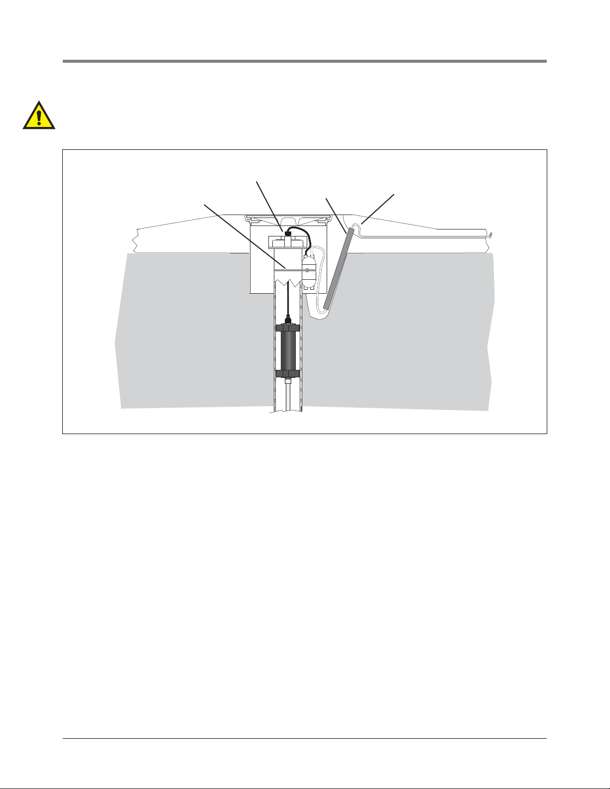
Figure 12 on page 13). A piece of flex conduit should be in place as shown to protect the cable.
1. Remove any existing hardware from the Vapor Extractor Riser so that it’s 4” NPT riser threads are exposed.
2. Use the extractor wrench tool (OPW Part Number: 89-0044) to remove the Ball Float Check Valve and
Extractor Cage inside the bottom of the 4” riser. Important! - Ball Float Check Valve and Extractor Cage may
be difficult to remove; use caution.
3. Remove any sludge from the bottom of the tank.
4. Assemble the probe floats, spacer rings, and cable as per the Mag Probe Assembly Manual.
5. Gently slide the float(s) to the bottom of the probe shaft. Important! - Handle probes carefully. Striking or
dropping the probe will result in loss of calibration and could cause permanent damage.
6. Carefully lower the probe into the riser pipe until the boot rests on the bottom of the tank.
7. Ensure that the cord grip nut on the new cap is loose so that the bushing can rotate freely.
8. Thread the probe cable through the bushing and nut on the cap, leaving a minimal amount of slack between
the probe and cap.
9. Install the cap onto the riser, threading it by hand until the gasket first contacts the riser pipe. Then lightly tap
the cap with a hammer to tighten it an additional 3/4 turn.
10. Splice the probe cable to the direct burial cable and seal following instructions shipped with the splice kit.
Observe polarity!
11. Bring the cable down the side of riser and secure into place with the tie wrap.
15
Page 20
Mag Probe Installation UST Installation - Vapor Extractor Riser W/O Coupling Adapter
879-18.eps
Tie wrap securing splice
enclosure to riser
Riser cap with cord grip
Flex Conduit
Direct Burial
Cable
WARNING! If Ball Float Check Valve was part of your Overfill Protection System, you now need to
consider another form of overfill protection (i.e. TLS console alarm, a drop tube with overfill
protection valve or some other accepted means).
Figure 14. Mag Probe Vapor Extractor Riser Installation - W/O Coupling Adapter
16
Page 21
Probe and Sensor Conduit Installation
WARNI NG
Probes and sensors operate in areas where flammable liquids and explosive vapors
may be present.
Improper installation may result in fire or explosion causing serious injury or death.
Practice the following:
1. Read thoroughly and follow the instructions shipped with each probe and sensor.
2. Probe and sensor wiring conduit must not contain any other wires.
3. Probe and sensor wiring and conduits must enter the console only through their
designated areas.
4. Power and communication wires must not enter the intrinsically safe
compartment of the console.
Wiring Run Methods
Two wiring run methods are commonly used for probes and sensors - Wiring pulled through buried, sealed 1/2”
conduit; or direct burial cable. NOTE: PVC conduit is an acceptable alternate where accepted by local codes [ref.
“National Electrical Code Compliance” on page 2 for more detail on cable requirements].
BURIED RIGID CONDUIT
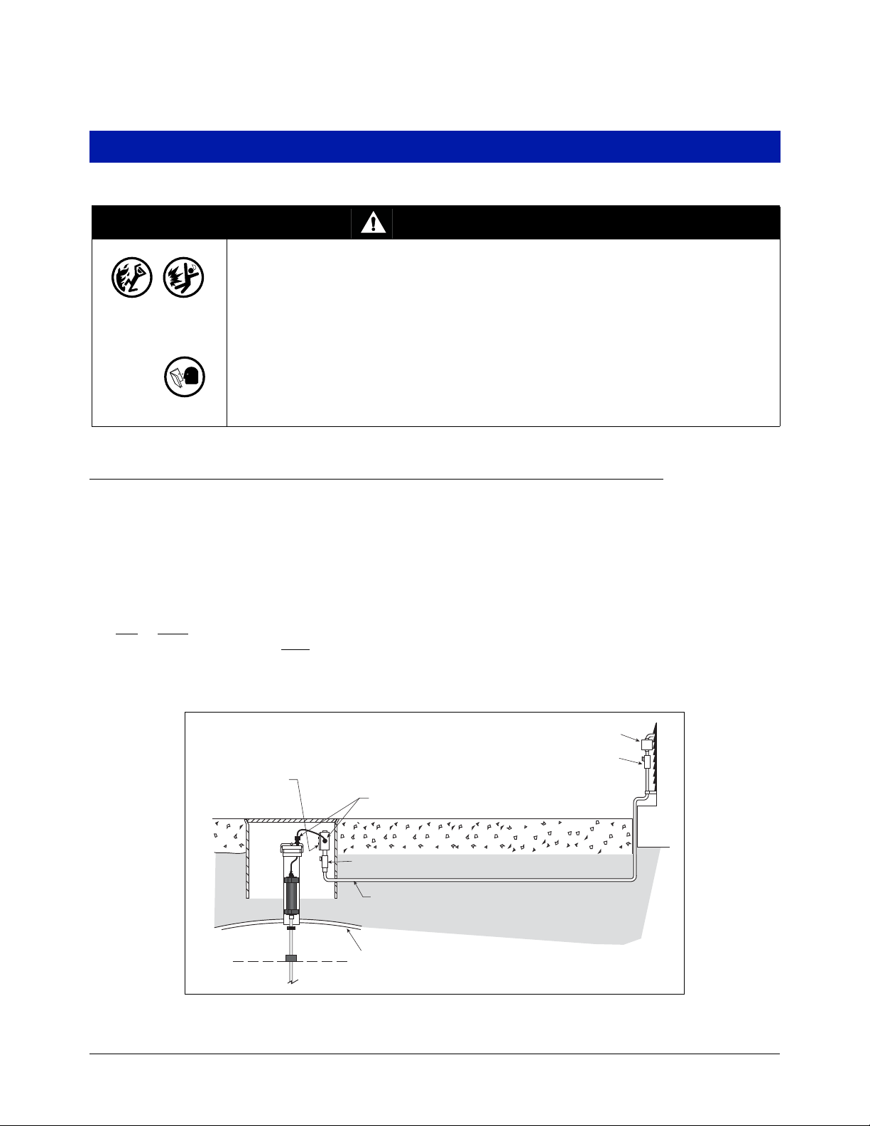
The preferred method, especially in new sites before driveway surfaces are paved, is to pull probe and sensor
wiring through buried 1/2” rigid conduit [Figure 15].
Pull two
console and the junction box at each
or three conductors shielded cable (as required). Individual wires should be color-coded between the
probe and sensor location (do not gang wires together, i.e., splicing all sump
sensor + wires together to run one wire back to console). Use single lengths of wire with no splices to ensure
optimum signal strength.
Weatherproof junction
box with 1/2-inch N.P.T.
threads (16 cubic inch
Splice Closure
Seal-Off
minimum)
Cord grip seals
.
.
.
.
.
.
.
..
.
.
.
.
.
.
.
.
.
.
.
.
.
.
.
.
.
.
.
.
.
.
.
.
..
..
..
.
.
.
.
.
.
.
.
.
.
.
.
.
.
.
.
.
.
.
.
.
.
.
.
.
.
.
.
.
.
.
.
..
..
.
.
.
.
.
.
.
.
.
..
.
.
.
.
.
.
.
.
.
.
.
.
.
.
.
.
.
.
.
.
.
.
.
.
.
.
.
.
.
.
.
.
.
.
.
.
.
.
.
.
.
.
.
.
.
.
.
.
.
.
.
.
.
.
.
.
.
.
.
.
.
.
.
.
.
.
.
.
.
.
.
.
.
.
.
.
.
.
.
.
.
.
.
.
.
.
.
.
.
.
.
.
.
.
.
.
Epoxy seal per NFPA spec
1/2'' rigid conduit (to console)
Tank
Figure 15. Example Probe Wiring Run In Buried Rigid Conduit
17
Page 22
Probe and Sensor Conduit Installation Wiring Run Methods
CAUTION: Since wires for multiple sensors may enter the console through a single conduit, it is recommended
that you use a different color-code for each wire or individually mark each wire to identify sensor inputs. Also, if the
intrinsically safe wires enter the building in a wiring trough, only Veeder-Root intrinsically safe wire can be in the
trough. Keep all low power (intrinsically safe) wiring isolated from high power wires in all wiring troughs.
DIRECT BURIAL CABLE
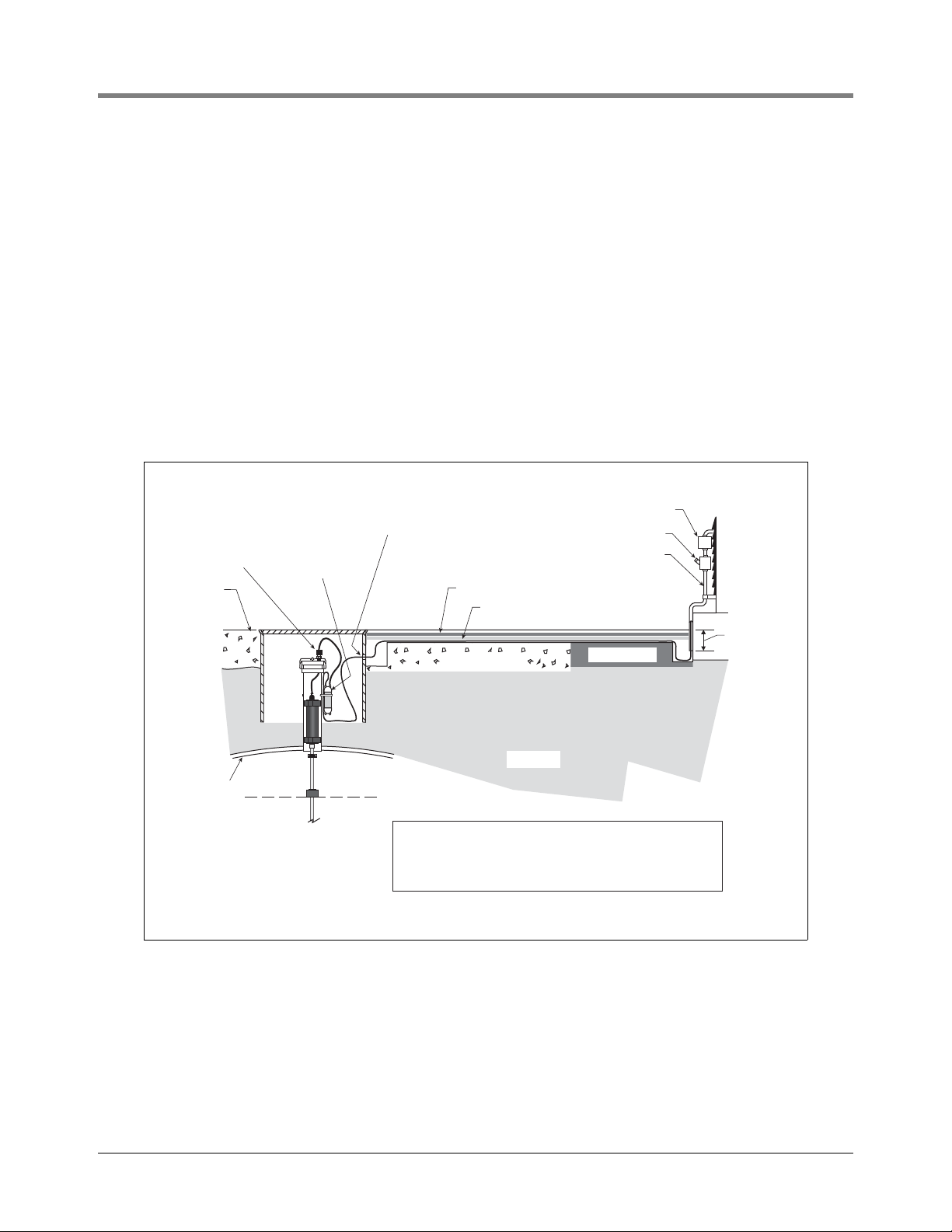
An alternative to trenching through existing pavement is to use direct burial cable. Before considering the direct
burial method, check to be sure that direct burial practices are acceptable at this location. The direct burial method
requires grinding using an abrasive wheel, a 1/4” to 3/8” wide by 1-1/4” deep groove (adding 1/4” of depth for
each additional cable) in the pavement surface, laying Veeder-Root supplied direct burial cable down in the bottom
of the groove, laying an expanded polyethylene foam backer rod over the cable(s), and then a placing a 1/4” to 1/
2” bead of silicone sealant over the backer rod to within a minimum of 3/8” below the pavement surface [see
Figure 16].
If you decide upon the direct burial method, consult the direct burial cable installation manual for detailed
installation instructions (reference manual 576013-858).
Splice closure
Cord grip
Grade
.
.
.
.
.
.
.
.
.
..
.
.
.
.
.
Epoxy filled
splice
enclosure
Drill oversized hole
in manhole for DB cable
890-SL silicone sealant
SOF ROD backer rod
.
.
.
.
.
.
.
.
.
.
..
.
.
.
.
.
.
.
..
.
.
.
.
.
.
.
.
.
.
.
.
.
.
.
.
.
.
.
.
.
.
..
..
.
CONCRETE
.
.
.
.
.
.
.
.
.
.
.
.
.
1
.
.
.
.
.
.
..
.
.
2
.
.
.
.
.
.
.
.
.
.
.
.
.
.
.
.
.
.
.
.
.
.
.
.
.
.
.
.
.
.
.
.
...
.
Seal-off
Rigid conduit
.
.
.
ASPHALT
3'' Min.
Tank
EARTH
1
Dow Corning Silicone Pavement Sealant
2
Expanded polyethylene foam rod - trademark of
Applied-Extrusion Technologies.
Figure 16. Example Probe Wiring Run Via Direct Burial Cable
18
Page 23
Wiring Module Bay Devices
Pump Input (Pump control from
self serve sys. or dispenser (120/240 Vac)
Output Relay
Connections
Pump
Sense
Pump In
Pump Return
NO
C
Dispenser Control
Connections
External Input Connections
NO
C
SWITCH
HOOK
STP CONTROL
(w/ RJ Relay Control Box)
Line (Power Panel 120 or 240 Vac)
Pump Ouput
Pump Return (Power Panel AC Neutral)
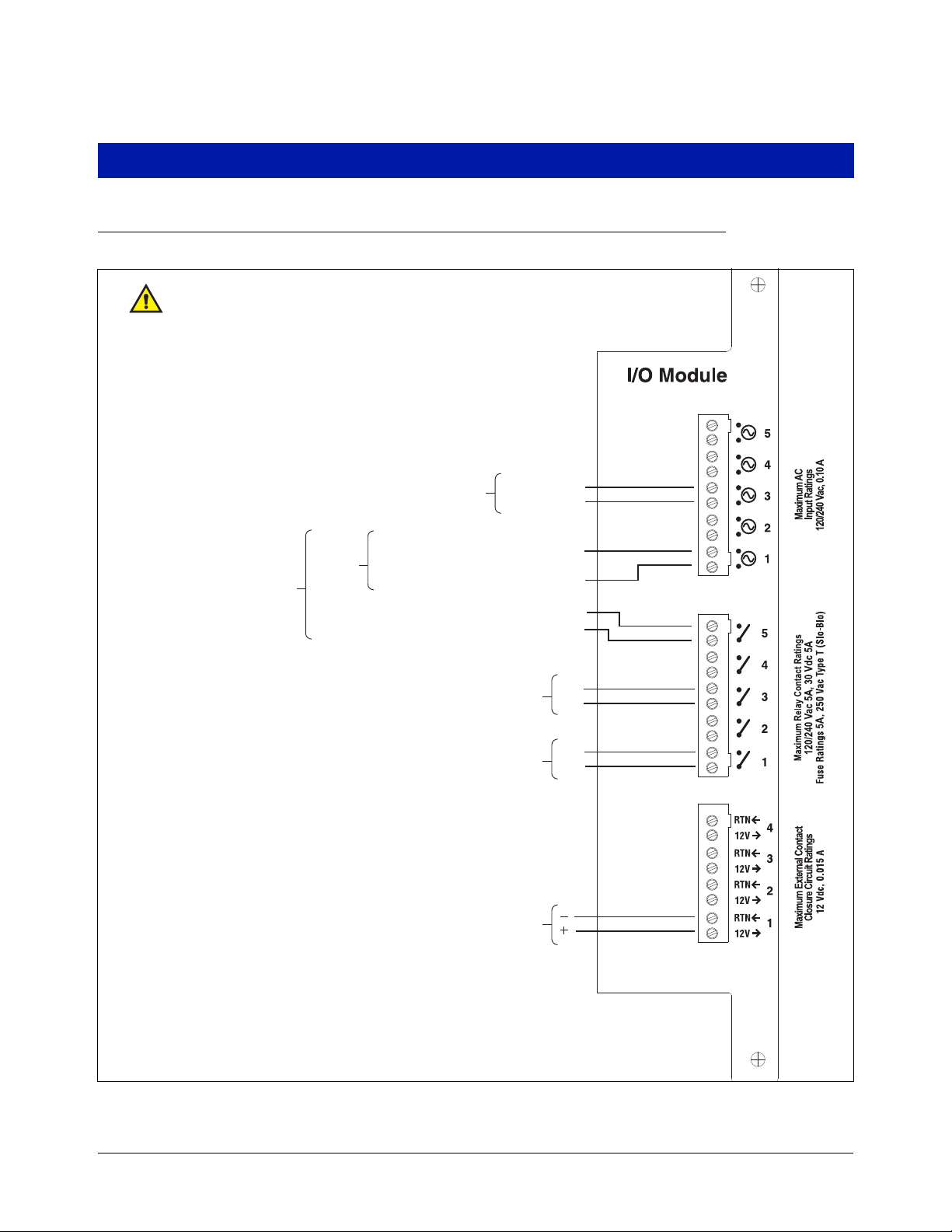
Reference Control Drawing number 331940-008
I/O Module Wiring
Figure 17. I/O Relay Module Connections
19
Page 24
Wiring Module Bay Devices MDIM Module Wiring
MECHANICAL DISPENSER INTERFACE MODULE
MDIM
L1
N
NC
NC
P1
P2
P3
P4
P5
P6
P7
P8
P9
P10
P11
P12
120 VAC
INPUT RATING
120 VAC MAX
0 30 AMP MAX
White
934-2.eps
Black
115 Vac Line (BLK)
Neutral (WHT)
Barrier
P/N: 7859
769780-008
Pulse
Transmitter
120 Vdc
Barrier
P/N: 7859
769780-012
Pulse
Transmitter
120 Vdc
Reference Control Drawing number 331940-008
Barriers and transmitters
must be UL Listed.
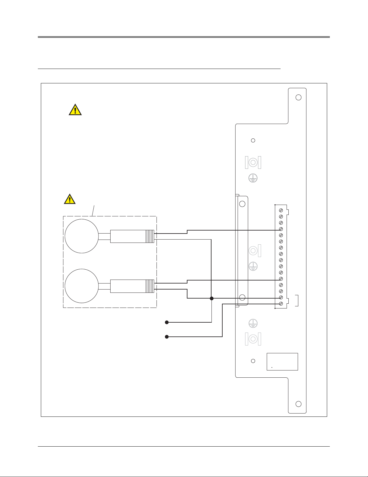
MDIM Module Wiring
Figure 18. MDIM Module Pulser Connections
20
Page 25
Wiring Module Bay Devices LVDIM Module Wiring
Set SW1 (on module's PC board)
to the EXTERNAL position.
Set SW1 (on module's PC board)
to the INTERNAL position.
Set SW1 (on module's PC board)
to the INTERNAL position.
Common
Pulser
+12
PetroVend System 2
PV270 Pump Relay Board
LVDIM
LOW VOLTAGE DISPENS ER INTERFACE MODULE
+
-
+
-
+
-
+
-
12
11
10
9
+
-
+
-
+
-
+
-
5
6
7
8
+
-
+
-
+
-
+
-
1
2
3
4
+
-
SOURCE
INPUT RATING
30 VDC MAX
0 1 AMP MAX
934-1.eps
Micon 200
Electronic Dispenser Head
Yellow #18 AWG
(Pulser Common Line)
Blue #18 AWG
(Volume Pulser Output)
GasBoy 9800 or Tokhiem 2600 Series
Electronic Dispenser Head
Pulse 1 (Red)
NC
Pulse 2 (Grn)
DC Ground (Wht)
DC Junction Box
Reference Control Drawing number 331940-008
CLASS 2 CIRCUITS
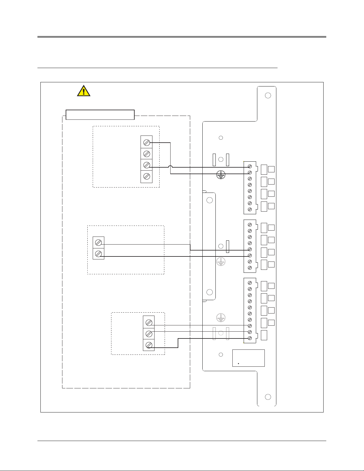
LVDIM Module Wiring
Figure 19. LVDIM Module POS/Pulser Connections
21
Page 26

For technical support, sales or
other assistance, please visit:
www.veeder.com
 Loading...