

Page 1

VEC-896 Vertical Antenna Instructions
VEC-896 Vertical Antenna
INTRODUCTION
The basic 40 meter quarter wave vertical antenna is 33' tall and requires a reasonably good
ground or counterpoise system to function properly. The usual way to eliminate the requirement
for a complicated and space consuming ground system is to center feed a 1/2 wave (in this
example a 66' tall) antenna.
These problems were solved by combining efficient end loading with a balanced center feedpoint
design. The result is a physically small vertical antenna that gives good performance and does
not require any type of RF ground system.
The reduction in size is accomplished by adding separate loading coils and capacitance hats at
each end of the antenna for the HF bands. The efficient end loading coils are wound on
fiberglass forms. The high quality materials and construction of the HF loading system allows a
maximum power rating of 1500 watts on 40, 20, 15 and 10 meters. The six and two meter bands
are covered with the addition of four quarter wave decoupling stubs on the side of the main
elements.
The power rating of this antenna varies from band to band. The PEP ratings are primarily
determined be the voltage breakdown of the components, while the CW ratings are generally
determined be components heating.
The following chart lists the power rating and the 2:1 VSWR bandwidth of this antenna:
Band Power Bandwidth
CW SSB RTTY
40 m 500 1500 700 40 KHz
20 m 750 1500 1250 250 KHz
15 m 1000 1500 1250 700 KHz
10 m 750 1500 1250 1.0 MHz
6 m 300 750 300 2.6 MHz
2 m 200 300 200 7 MHz
The weight and wind load of this antenna is 15 pounds and approximately 2 square feet
respectively.
Warning:
Improper installation and assembly can be hazardous! Read these
instructions thoroughly before attempting to assemble, install or operate this
product! High power transmitting devices produce voltages that can cause
severe burns or other injuries.
1
Page 2

VEC-896 Vertical Antenna Instructions
CHOOSING A LOCATION FOR THE ANTENNA
The best performance on receiving and transmitting will be obtained by mounting the antenna in
a clear location above or away from buildings, towers, feedlines, utility wires, and other
antennas. While your own ingenuity and particular circumstances will determine the final
mounting method, we'll pass along a few ideas for both permanent installation and portable
operation.
Warning:
•••• Never mount this antenna in a location that will permit unsuspecting people to come in
contact with the loading spokes or any other part of the antenna.
•••• Never mount this antenna where a mechanical failure might allow the antenna to contact
power lines or other utility wires.
•••• Always ground the feedline at the point where it enters a building to a good earth ground for
lightning protection.
• Always follow the guide lines for antenna installations as recommended by the US consumer
product safety commission.
Always mount this antenna so that it is out of the reach of adults as well as
children. The capacitance elements can cause injury and or severe RF burns.
Permanent Installation
The ideal installation is a rigid pole or roof mount that puts the antenna completely in the clear.
If the ideal installation is not possible, choose the best compromise. TV mast or steel water pipe
are suitable mast materials. This antenna will mount on masts between 1 and 1-1/2" OD. The
use of soft or thin wall masts is not recommended. Never use mast made of soft material or thin
wall aluminum, such as aluminum tubing and conduit.
The VEC-896 will perform quite well even at ground level, which means the lower capacitance
hat should be at least 5 ft above ground level on a short rigid mast. However, the antenna
installation MUST be protected (with non-metallic fencing) to provide personal safety and to
prevent damage to the antenna itself.
Portable Operation
This antenna may be disassembled to the extent necessary for transporting to a temporary
location. If possible, only remove the two HF loading coil assemblies. Leave the two main
elements with the 2 and 6 meter stub assemblies intact. Some retuning may be required after
moving the antenna.
Note: Even for temporary or portable operation, do not be casual about selecting a suitable
mast. If the antenna falls it will be damaged and may cause serious injury. Whatever
type of installation you choose, remember that the antenna should be installed where it
can never be contacted by people or animals.
2
Page 3

VEC-896 Vertical Antenna Instructions
TOOLS AND TIME REQUIRED FOR ASSEMBLY
The estimated assembly time for this antenna is two hours. Antenna assembly requires the
following hand tools:
1/4" nut driver
3/8" open end wrench
5/16" nut driver (or 1/4" blade standard screwdriver)
7/16" nut driver
7/16" open end wrench
Large wire cutters
#1 phillips screwdriver at least 6" long or longer
#2 phillips screwdriver
suitable eye protection
In addition, you will need two stable supports at least 30" tall (such as saw horses or trash cans)
and a short (6-8') temporary mast (1 to 1-1/2" OD) for temporary mounting during tuning.
VEC-896 PARTS LIST
As you unpack your antenna you should find the parts in the following list.
2 Fiberglass Coil Assemblies
two bundles of wire capacitance spokes 28 short, 12 medium, (and 4 spare long spokes)
one bag of clamps 10 hose clamps and 2 saddle bolts
5' upper radiator, 6061-T6 AL tubing, 1 1/8" OD with the 6 and 2 meter stubs inside
5' lower radiator, 6061-T6 AL tubing, 1 1/8" OD (this tube has two holes through it)
one bag of short 6-32 stainless screws (you will only use 40, the rest are extra)
4 small "L" brackets with holes one end
4 long "U" channel "L" brackets
4 flat fiberglass insulators
2 hollow white nylon insulators
1 solid rod fiberglass center insulator
5 split ring 1/4" washers
5 1/4" dia. 7/16" head bolts
5 1/4-20 x 7/16" nuts
20 6-32 x 1/2" stainless screws
20 6-32 x 1/4" nuts
8 10-32 x 3/8 nuts
For installation you will need some items not supplied with the antenna installation kit.
A 6'-8' rigid mast or other mounting pipe between 1" and 1.5" outside diameter. (suitable
materials include TV mast sections, galvanized iron pipe, or heavy duty rigid conduit.)
3
Page 4

VEC-896 Vertical Antenna Instructions
Quality low-loss 50-Ohm coax with a PL-259 from antenna to transmitter.
Either a SWR meter or Analyzer (such as the Vectronics SWR-584)
SAFETY PRECAUTIONS
Warning:
1. Be careful while climbing and carrying the antenna. It is heavy enough to cause you to lose
your balance if it is handled too casually or if the capacitance spokes are snagged on a gutter,
ladder, tree limbs and so forth.
2. Mount the antenna high enough so that it is out of reach. The ends of the capacitance spokes
can cause eye injury, serious RF burns or both.
3. Make sure that the mast is sturdy enough to support the weight (15 pounds) and the wind load
(approximately 2 square feet).
You can be killed if the antenna, feedline, or the equipment used to install the
antenna accidentally contacts any utility lines. Never install an antenna near
power lines!
ASSEMBLY and INSTALLATION PROCEDURE
During assembly of this antenna refer to the figures in this manual and the picture on the inside
cover. The assembly instructions tell you how to first install the balun and then connect the
upper and lower elements. Then the 2 and 6 meter stub elements are installed. Last the loading
coil assemblies are assembled and installed on the upper and lower elements.
If you do not wish to install the 6 and 2 meter stubs operation on the other bands will not be
affected. Skip step 4, do not install the hose clamps in step 10 and skip steps 13-18.
After the antenna is assembled it is checked and adjusted for resonant frequency and SWR. It
can then be mounted on a tower or rooftop and given final adjustments See the Tuning The
Antenna section for details.
Note: Wear safety glasses whenever working near or on this antenna.
Warning:
Do not tighten the screws th at connect the loading coil terminal lugs to the
capacitance hats or you will BREAK the fiberglass form. If the terminal lugs
loosen tighten the NUT down on the lug.
Step-By-Step Procedure
4
Page 5
VEC-896 Vertical Antenna Instructions
1. Prepare a temporary ground-level mounting mast that will permit easy initial testing and
adjustment. Set up saw horses or any other stable support (plastic trash cans or folding
tables, etc.) near the mast.
2a. Sort out the parts you have unpacked into groups of similar parts. Be sure all the parts are
available.
3. After examining the antenna parts, gather the tools needed for basic assembly. At the
minimum these consist of:
#1 Long Phillips screwdriver for capacitance spoke screws
#2 Phillips screwdriver for other 6-32 screws
1/4" standard screwdriver or a 5/16" nut driver for hose clamps.
3/8" wrench for 6 and 2 meter stub nuts
Two 7/16" open end wrenches or one wrench and one nut driver for "U" BOLTS and
center insulator bolts.
Wire cutters for trimming capacitance spokes.
Safety glasses.
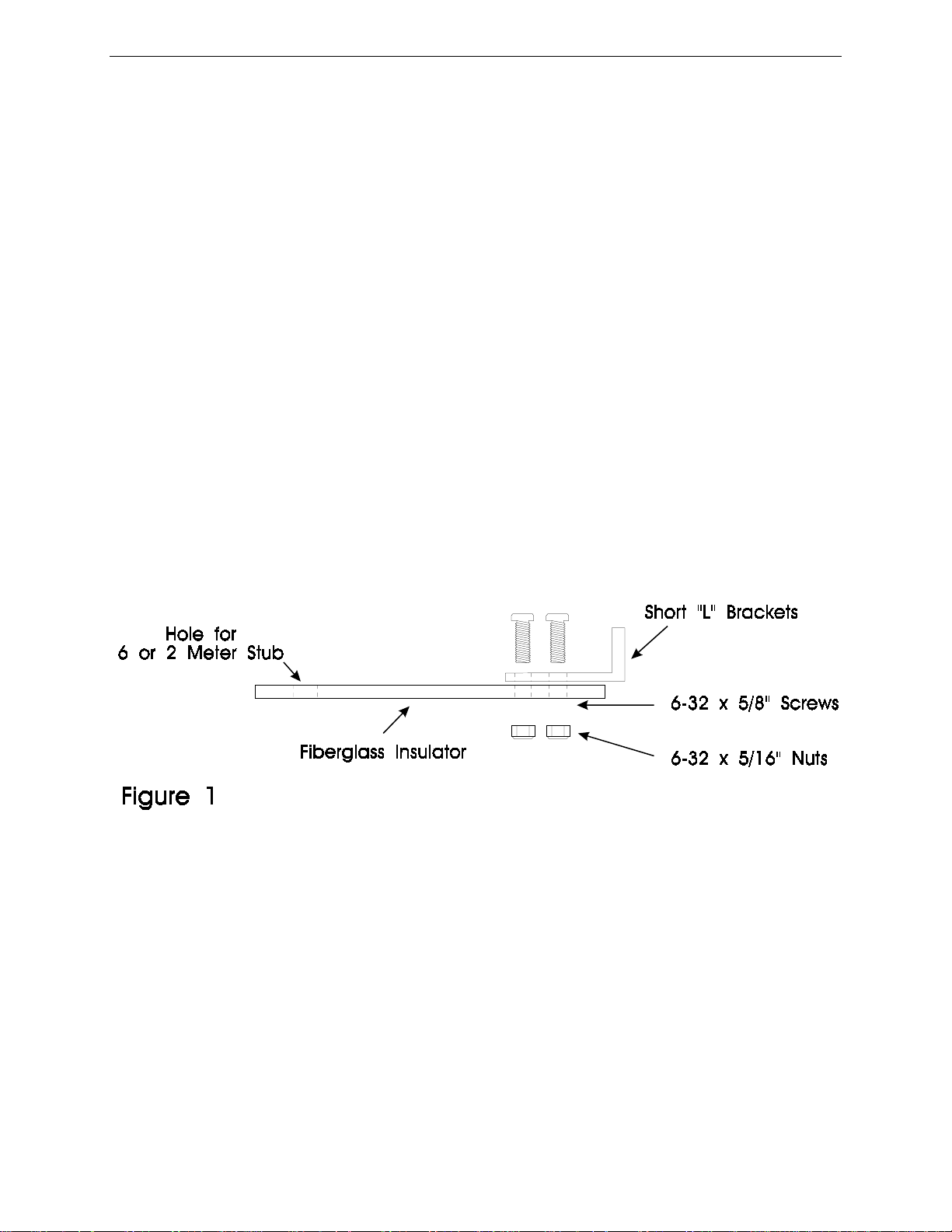
4. Assemble the four small "L" brackets to the 4 long fiberglass insulators with the 6-32 x
1/2" screws and the 6-32 x 5/16" nuts as shown in Figure 1.
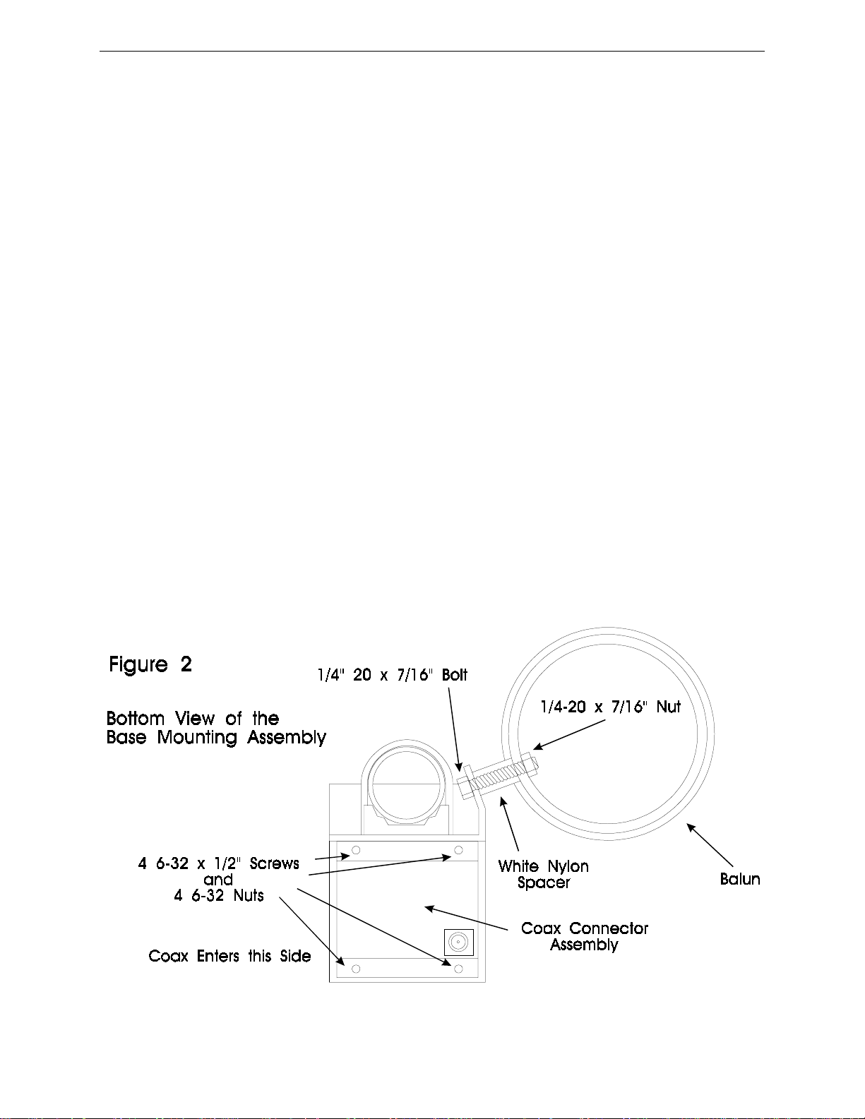
5. Bolt the top balun hole loosely to the top hole in the base mounting assembly with a 1/4-
20 x 7/16" nut and the 1/4" x 7/16" head bolts. Use the hollow white nylon spacers to
separate the balun from the mounting bracket. Finger tighten only. See Figure 2.
6. Bolt the bottom balun hole to the bottom hole in the base mounting assembly as in Step 5.
7. Tighten the balun bolts with a 7/16" wrench.
8. Bolt the coax connector assembly to the base mounting assembly with four 6-32 x 5/8"
screws and 6-32 nuts. See Figure 2.
5
Page 6
VEC-896 Vertical Antenna Instructions
9. Slide the bottom radiator (the one with two sets of holes) over the fiberglass rod with the
holes that are 2" from the end toward the base mounting bracket. Slide a hose clamp to the
bottom of the element. The radiator should butt against the insulating plastic of the base
mounting bracket. Install a 1/4 x 7/16" bolt through the element and fiberglass rod and
tighten with a lock washer and 1/4 x 7/16" nut.
10. Slide three more hose clamps over the bottom elem ent. Tighten the hose clamp installed
in step 9 over the slit in the bottom element. This clamp will make the antenna more rigid.
11. Insert the fiberglass center insulator into the bottom element and insert a 1/4" x 7/16" head
bolt with a lock washer through the hole. Thread a 1/4" x 7/16" nut on the other end.
Finger tighten only. See Figure 3. Slide a hose clamp over the center insulator. Tighten
the hose clamp on the slit in the bottom element. Slide another hose clamp over the
insulator.
12. Slide the top 1 1/8" diameter element over the center insulator and install the 1/4" x 7/16"
head bolt and nut as in step 10. Tighten the hose clamp over the slit in the top element
until the element will not sway.
13. Slide three hose clamps over the top element.
Note: The upper and lower stubs (U-channel "L" brackets) on each band should not be installed
perfectly in line. There should be enough offset so that the threaded ends won't touch if
the stubs are fully shortened. The alignment of the stubs will not affect operation. See
Figure 5.
6
Page 7

VEC-896 Vertical Antenna Instructions
14. Clamp the four long U-channel "L" brackets to the elements 1/4" above and below the
center insulator bolts. See Figure 4 and Figure 6.
15. Mount the two short stubs by threading a 10-32 x 3/8" nut 1/2" from the end of the
threads, toward the elements unthreaded end. This will leave a large area of the threads
exposed at the end of the element. Add a second nut to sandwich the bracket between the
two nuts. See Figure 4. The two short stubs should be mounted opposite from the
balun. See Figure 5.
7
Page 8

VEC-896 Vertical Antenna Instructions
8
Page 9

VEC-896 Vertical Antenna Instructions
16. Mount the two long stubs by treading a
10-32 x 3/8" nut, 1/2" from the
elements threaded end. This will leave
only a small amount of threaded area
below the nut. Add a second nut to
sandwich the bracket between the two
nuts. See Figure 4. The two long
stubs elements should be on the
same side as the balun. See Figure 5.
17. Install two long fiberglass insulators
over each long stub one approximately
20" and the other 14" from the
unthreaded ends of the long stubs by
clamping them in place with hose
clamps. See Figure 6.
18. Install the remaining long fiberglass
insulators over the short stubs
approximately 5" from the outside
ends of the stubs. See Figure 6.
9
Page 10

VEC-896 Vertical Antenna Instruction Manual
19. Install the short 6-32 screws in the ring of both loading coil assemblies. Do not thread the
screws completely in. Put the medium capacitance spokes in the six holes in these rings
on both coil assemblies. Tighten the screws until the spokes are snug. At this point you
should be able to turn the coil assemblies over and they should balance on the long spokes.
USE THE #1 PHILLIPS SCREWDRIVER HERE.
Important:
20. Install the screws in the next set of rings and install six short spokes in these rings.
21. Install the next groups of four short spokes on each loading coil assembly.
22. Check the bare wires running along the side of the loading coil assembly to be sure that
there is at least 1" of clearance between the bare wire and the capacitance spokes. It is
okay to bend the bare wire enough to clear the spokes properly. See Figure 7.
23. Remove the nuts on the center insulator bolts of the main element and install the center
conductor lug of the coax under the upper element nut and the shield lug under the
bottom element nut. Hol d the nut in place and turn th e bolt head to tighten these bolt s so
that the lug does not break off the end of the coax. Be sure to dress the coax so it loops up
in a drip loop so water cannot get into the end. See Figure 8.
Do not use a high torque electric screwdriver to mount the capacitance
spokes. The screw heads will be sheared off if too much torque is applied.
9
Page 11

VEC-896 Vertical Antenna Instruction Manual
24. Use the three wire ties to affix the coax to the antenna as illustrated on the inside cover.
Warning:
25. Slide a hose clamp over the top element. Mount the top coil assembly to the antenna by
inserting the fiberglass insulator in the top element. Tighten the bus wire from the coil
assembly under the hose clamp. Make sure the loading coil assembly is secured.
26. Mount the coil assembly with the angle mounting bracket three to four inches from the
bottom insulator of the antenna. See figure on inside front cover.
27. Double check the tightness of all the hardware you installed and then mount the antenna
on the short temporary tuning mast (6 to 8 feet).
28. Tune the antenna, see the next section.
29. Mount the antenna in its permanent location. Slight re-tuning may be necessary.
To prevent arcing and destruction of the coax cable, do not allow the coax to
come within 1 inch of the base mounting bracket.
FREQUENCY AND SWR ADJUSTMENT
This antenna covers wider frequency ranges on the higher bands, and narrower segments on the
lower frequency bands. The 40 meter band has the narrowest range of operation (approximately
40 KHz) and is the most sensitive to adjustments.
The entire antenna must be accessible during initial coarse tuning and testing. Any repair or
adjustment to the antenna after it is installed on a tall support will make adjustments difficult and
time consuming. It is best to install the antenna on a short temporary mast or pipe that is located
in a reasonably clear location for tuning. The antenna should be mounted vertically with the base
of the antenna around six feet above ground to make tests and adjustments easy.
Hint: The use of a small tripod will make tuning this antenna easy. With the help of another
person it is easy to lean the antenna, while it is fastened to the tripod, to lower it and
make the necessary adjustments.
The SWR can be measured by using a transmitter and SWR bridge or an SWR Analyzer such as
the Vectronics SWR-584. The best location to make SWR measurements is at the base of the
antenna. If the measurements are not taken at the base of the antenna, the antenna must be fed
with a reasonably short length of good quality 50 ohm coaxial cable to insure proper results. If
using a transceiver and SWR meter, set the transceiver to the lowest power possible to make
measurements.
10
Page 12

VEC-896 Vertical Antenna Instruction Manual
Please read the following hints:
•••• The normal resonant frequency of this antenna is at or just below the bottom of each
amateur band. This allows the user to "trim" a small amount off the inside end of the
capacitance spokes to raise the resonant frequency. Conversely, adding a longer capacitance
spoke will lower the resonant frequency of a loading assembly. Spare spokes are included in
case you need to lower the resonant frequency of the antenna.
•••• If you suspect the resonant frequency is lower than your equipment can detect, for
example below 6.0 MHz, take one 40 meter spoke entirely off the antenna (top and bottom
hats). Make another attempt to measure the resonant frequency. If you still are unable to find
the resonant frequency, check another band. If none of these tests produce a good SWR on
any frequency, substitute a 50 ohm load for the antenna to test the feed line. If the SWR
checks good, you will have to double check the antenna assembly for shorts or opens at the
feed point and the connector box.
•••• If the antenna operates normally higher than the band after one spoke is removed,
install all the spokes and trim one spoke simultaneously from top and bottom hats in one inch
steps until you find the resonant frequency within the range of your equipment.
•••• Once you find the resonant frequency, use the chart located on the following page to
estimate the amount of spoke length to cut so the antenna will resonate at your favorite
section of the band.
Important
Always start tuning on 40 meters and adjust each band progressively higher
:
in frequency.
TUNING THE ANTENNA
Remember: This antenna is a balanced dipole. If changes were made to one side only, the
dipole will be balanced. For that reason, any changes you make on the bottom
capacitor hat should be done in the same manner on the top capacitor hat to keep
the dipole balanced.
Measure and record the frequency that the lowest SWR occurs on for each band. The lowest
SWR should be at or below the bottom end of each HF band. The SWR should be below 2:1 at
resonance on each band.
The following is a typical chart for initial measurements of a new antenna before tuning:
40 M 1.6:1 at 6.99 MHz 10 M 1.6:1 at 27.97 MHz
20 M 1.2:1 at 13.9 MHz 6 M 1.2:1 at 51 MHz
15 M 1.2:1 at 20.85 MHz 2 M 1.2:1 at 146 MHz
11
Page 13

VEC-896 Vertical Antenna Instruction Manual
If the resonant frequency is lower than your equipment can detect take one spoke off (top and
bottom hats) to raise the resonant frequency. Measure the resonant frequency and calculate the
approximate resonant frequency as if the spoke was in place using the chart on the next page.
Warning:
Note: Always tune the lowest frequency bands first.
Shortening the spokes from the looped end degrades safety and power
handling capabilities!
TUNING THE LOW FREQUENCY BANDS
Note: Always trim the same amount of spoke length from both capacitor hats of the antenna
(top and bottom) to keep the dipole balanced.
40 Meters Band:
1. Select a frequency 50 KHz below the desired operating frequency. Use this frequency as a
target.
2. Measure the resonant frequency of the antenna at this band. Determine the frequency shift
required by subtracting the initial frequency from the desired frequency. Use the results and
the chart below to determine the proper amount of spoke length to be cut.
3. If the calculated amount of spoke shortening exceeds 8", cut one inch from the inside end of
all six spokes for each 8" calculated.
4. Return to the first step. Keep repeating these steps until done.
Example: The antenna measure 6.95 MHz, the desired frequency is 7.25 MHz, less 0.05 MHz
(50 KHz below desired frequency) for a difference of 0.2 MHz or 200 KHz. This
would require the trimming of 8" from one spoke in each top and bottom hat. Instead,
cut one inch from all 6 spokes (top and bottom hats) and measure the resonant
frequency. Assume the new resonant frequency is close to the wanted one. A single
spoke (from top and bottom hats) can not be trimmed to adjust the antenna to
resonance.
40 M: 1" trimmed off a pair of spokes equals approximately 25 KHz
20 M: 1" trimmed off a pair of spokes equals approximately 100 KHz
15 M: 1" trimmed off a pair of spokes equals approximately 175 KHz
10 M: 1" trimmed off a pair of spokes equals approximately 250 KHz
12
Page 14

VEC-896 Vertical Antenna Instruction Manual
20, 15, and 10 Meter Bands
Now tune progressively higher frequency HF bands by using the same techn ique used for the
40 meter band. Set the target frequency 30 KHz lower than the desired operating frequency for
these bands. 20 meters must be the second HF band adjusted, 15 the third, and 10 meters last.
After adjusting 10 meters go back and check the other bands. Tighten all spoke screws. (Use the
chart above for cutting at each band.)
TUNING THE HIGH FREQUENCY BANDS (VHF)
The six and two meter bands are tuned by lengthening or shortening the threaded portion of the
stubs. See Figure 9. This adjustment is very coarse. If the frequency is still too low with the
stub element extension at a minimum, the unthreaded ends of the stubs can be trimmed. Once
again the lower frequency stub (6 meters) should be adjusted first.
The six meter stub covers from 50 to 54 MHz as it is adjusted. Be careful because the third
harmonic resonance of the six meter stub will show up as a low SWR on the third harmonic of
it's setting, usually between 150 and 160 MHz. The range of the two meter stub allows
frequencies as low as 130 MHz to be covered with the stub fully extended and 148 MHz with the
stub fully contracted.
Final frequency adjustments can be made by trimming spokes on the bottom hat only when the
antenna is permanently mounted. The minor adjustment of bottom spokes without the
symmetrical trimming of the top spokes is perfectly acceptable so long as the frequency is
changed less than 30 KHz on 40 meters and 60 KHz on the higher bands with the final
adjustment. The result of attempting to move the resonant frequency too far with only the
bottom spokes will be an increase in the SWR of the antenna at the resonant frequency.
13
Page 15

VEC-896 Vertical Antenna Instruction Manual
GROUNDING CONSIDERATIONS
Although this antenna is designed to operate efficiently without the requirement of an earth
ground, SAFETY GROUNDING MUST STILL be provided to protect equipment, property and
persons from the hazards of lighting strikes and other weather related electrical discharges. In
addition the coaxial cable feeding the antenna should have the shield grounded to eliminate the
risk of any indoor equipment failure from allowing hazardous voltages from appearing indoors
and creating a shock hazard.
Adequate protection can be accomplished by grounding the shield of the coax where it enters the
building to a good earth ground or directly burying the cable in the earth for several feet before it
enters the building. The coaxial cable should be totally disconnected from the station during
threatening weather conditions for maximum lightning protection.
A less effective method of protecting station equipment is to install an in-line coaxial lightning
arrestor with a heavy duty ground wire to a suitable earth ground, or a safety switching system as
part of the basic ham station equipment.
MAINTENANCE
Your antenna is constructed of heavy duty non corrosive materials and should withstand normal
climates for many years. The use of some type of coaxial connector moisture protection is
recommended at the bottom coax connection and also around the center-feed connections,
especially in coastal areas where salty mist is commonplace.
GE makes a pure silicone grease called "SILICONE DIALECTRIC COMPOUND" that can
be applied SPARINGLY to the threaded area of the female connector. This compound, or even a
clear silicone heatsink compound, will prevent moisture from entering the connector through the
threads and protect the connectors from corrosion. THIS IS THE SAME TYPE OF SEALER
THAT COMMERCIAL ANTENNA INSTALLERS AND CATV COMPANIES USE WITH
GREAT SUCCESS.
A less desirable, but still adequate sealer is the automobile seam sealer commonly sold as "coax
seal". This is a semi-pliable black sealing compound.
When installing any "coax seal", NEVER completely cover the barrel of the coax connector. The
sealer should ONLY be placed near the junction of the threaded part of the chassis connector and
the knurled area of the male connector. This will leave the bottom of the male outer sleeve open
and permit the connector to "breathe" so it does NOT collect moisture!
IMPORTANT FOR COASTAL AREA OPERATORS: It is advisable to use some type of
silicon spray (circuit board type from Radio Shack) on the capacitor rings to prevent corrosions
between the aluminum and the stainless steel screws. Corrosion on capacitor rings tends to make
it difficult to remove the spokes to retune the antenna.
14
Page 16

VEC-896 Vertical Antenna Instruction Manual
TECHNICAL ASSISTANCE
If you have any problem with this unit first check the appropriate section of this manual. If the
manual does not reference your problem or your problem is not solved by reading the manual you
may call VECTRONICS at 601-323-5800. You will be best helped if you have your unit,
manual and all information on your station handy so you can answer any questions the
technicians may ask.
You can also send questions by mail to VECTRONICS, 1007 HWY 25 South, Starkville, MS
39759 or by Fax to 601-323-6551. Send a complete description of your problem, an explanation
of exactly how you are using your unit, and a complete description of your station.
15
Page 17

VEC-896 Vertical Antenna Instruction Manual
VEC-896 Vertical Antenna
Instruction Manual
Table of Contents:
Introduction..............................................................................................................1
Choosing a Location for the Antenna...................................................................... 2
Permanent Installation...................................................................................2
Portable Operation.........................................................................................2
Tools and Time Required for Assembly.................................................................. 3
VEC-896 Parts List..................................................................................................3
Safety Precautions....................................................................................................4
Assembly and Installation Procedure.......................................................................4
Step-By-Step Procedure................................................................................ 4
Frequency and SWR Adjustment ............................................................................ 10
Tuning the Antenna ................................................................................................. 11
Tuning the Low Frequency Bands........................................................................... 12
40 Meters Band .............................................................................................12
20, 15, and 10 Meters Band...........................................................................13
Tuning the High Frequency Bands (VHF)............................................................... 13
Grounding Considerations.......................................................................................14
Maintenance............................................................................................................. 14
Technical Assistance................................................................................................15
16
 Loading...