

Page 1

VEC-884 Owner's Manual
Contents
Fast Start.............................................................................................................1
Before Reading This Manual.......................................................................iv
Chapter 1 Introduction.....................................................................1-1
Introduction to DSP.........................................................................................1-2
Product Overview.............................................................................................1-3
Block Diagram...................................................................................................1-4
Front Panel Layout...........................................................................................1-5
Back Panel Layout............................................................................................1-6
Filter Specifications.........................................................................................1-7
Unit Specifications............................................................................................1-8
General Specifications...........................................................................1-8
Input/Output Specifications................................................................1-8
Chapter 2 Installation.......................................................................2-1
Back Panel Connections...............................................................................2-2
Basic Connections...........................................................................................2-3
Setting Receive Audio Level (Input Level)......................................2-4
Increasing Headphone Audio Level..................................................2-4
Passing Sidetone..............................................................................................2-5
XMIT/RECEIVE Connection.................................................................2-5
CW Sidetone Filter..................................................................................2-6
DSP to TNC Connections..............................................................................2-6
Chapter 3 Operation..........................................................................3-1
Initial Operation..................................................................................................3-2
CW Operation............................................................................................3-3
SSB (and other voice modes) Operation.......................................3-4
Front Panel Description................................................................................3-6
PWR LED.....................................................................................................3-6
Input Level LED..........................................................................................3-6
AGC Button.................................................................................................3-7
Program Button.......................................................................................3-7
Memory Button.........................................................................................3-8
Filters Switch..............................................................................................3-8
Tunable Filters Controls........................................................................3-9
Manual Notch Button.............................................................................3-10
i
Page 2

VEC-884 Owner's Manual
Auto Notch Button..................................................................................3-11
Noise Reduction Control.......................................................................3-12
Noise Reduction Button........................................................................3-12
Volume Control.........................................................................................3-12
Speaker Button.........................................................................................3-12
DSP Button.................................................................................................3-13
Power Button.............................................................................................3-13
Chapter 4 Advanced Features......................................................4-1
Memory Filters..................................................................................................4-2
Saving Memory Filters...........................................................................4-2
CW Spotting Tone............................................................................................4-4
Measuring Frequency............................................................................4-4
Talk..........................................................................................................................4-5
Talk Operation............................................................................................4-5
Jumper Settings...............................................................................................4-8
Talk Settings...............................................................................................4-8
Auto Notch Aggressiveness...............................................................4-8
Normal Jumper Settings......................................................................4-8
Normal Jumper Settings Chart................................................4-9
Setting the CW Sidetone Filter..........................................................4-10
Pre-Set Filters............................................................................................4-11
Data Mode Jumper Settings Chart........................................4-12
Chapter 5 Filter Description..........................................................5-1
LR/HR Filter [1]................................................................................................5-2
Band-stop Filter.........................................................................................5-3
BP Filter [2].........................................................................................................5-4
2BP Filter [3]......................................................................................................5-5
CW Filter [4].......................................................................................................5-6
CW Sidetone Filter..................................................................................5-6
SSB Filter [5].......................................................................................................5-7
RTTY Filter [6]....................................................................................................5-7
HF PACKET Filter [7].......................................................................................5-7
AMTOR Filter [8]...............................................................................................5-8
PACTOR Filter [9].............................................................................................5-8
SSTV/FAX/WeFAX Filter [10]..................................................................5-8
Manual Notch Filter.........................................................................................5-9
Automatic Notch Filter..................................................................................5-10
Noise Reduction Filter....................................................................................5-10
Limited Filters.....................................................................................................5-11
Overlapped Filters............................................................................................5-12
ii
Page 3

VEC-884 Owner's Manual
Appendix A ..............................................................................................A-1
Self-Test................................................................................................................A-2
In Case of Difficulty...........................................................................................A-4
Technical Assistance......................................................................................A-4
MFJ Pre-wired Cables and Open End Cables......................................A-5
Pre-Set and Memory Filters Settings Chart........................................A-6
iii
Page 4

VEC-884 Owner's Manual
Before Reading This Manual
This manual is divided into two parts. The first part, called Fast Start, is meant
for people who need to know nothing except how to minimally install the unit
and operate it on CW and SSB. The second part, Chapters 1 to 5, is meant
for operators who want or need more information. Detailed description of the
unit and its operation are described in these chapters.
The first chapter is an introduction to DSP and the VEC-884. The second
chapter tells about the back panel and how to install the unit with a radio or
TNC. Chapter 3 tells how to operate the unit in CW and SSB and describes
the various controls. Advanced Features, Chapter 4, tells how to use the
special features o f the VEC-884. The las t c hapter is a des c riptio n of the digital
filters used in this unit.
The appendix has two important sections, troubleshooting and technical
assistance. There is also a self-test for the unit's digital circuitry and controls.
Refer to these sections if you should have any problem with your new VEC-884.
Important:
Please read this section to become familiar with the terms
and mechanics used in this manual.
Whenever the manual text discusses a control, jack, or level adjustment, the
name will appear in Bold.
Example: Plug a headphone into the Headphones Out jack for ...
The Memo ry/Nor mal Filters button will be referred to simply as the Me mory
button throughout this manual.
Definitions for the abbreviations used in this manual are listed below:
LR = Low Reject (Cutoff Frequency)
HR = High Reject (Cutoff Frequency)
f1 = Center or Notch Frequency #1
f2 = Center or Notch Frequency #2
fc = Center Frequency
BW = Bandwidth
FIR = Finite Impulse Response
IIR = Infinite Impulse Response
LMS = Least Mean Square
WPM = Words Per Minute
Explanation of graphical symbol:
iv
Page 5
VEC-884 Owner's Manual
The exclamation point within an equilateral triangle is intended to
alert you of conditions that may be damaging to the product or
resulting in a risk of electric shock to persons.
v
Page 6

Page 7

VEC-884 Fast Start
Fast Start
Beginners' Installation and Operation
To install and use the VEC-884 in the simplest way possible, follow the steps
below.
throughout this Fast Start section. SSB also works with AM and FM voice.
1. Install the unit. Follow the installation diagram on the facing page.
2. Set the controls as follows:
3. Apply external power and press and lock the DSP's Power button. The
4. Set the input level.
On some steps we give you a choice of CW or SSB. Choose one
Control Position Meaning
AGC button: out AGC off
Program button: N/A N/A
Memory/Normal button: out Tunable/Pre-Set
Filters switch:
Tunable Filters left knob: center middle center freq.
Manual Notch button: out manual notch off
Tunable Filters right knob: full counter-clockwise widest bandwidth
Auto Notch button: out auto notch off
Noise Reduction control: full counter-clockwise minimum reduction
Noise Reduction button: out noise reduction off
Volume control: full counter-clockwise minimum volume
Speaker button: in speaker on
DSP button: out DSP bypassed
Power button: out VEC-884 off
PWR LED on the front panel should light red. If it is green, press the
Memory/Normal Filters button.
a. Tune your radio to a
b. Set your
c. Use a screwdriver to adjust the Receive Audio Adjust (on the back
panel of the DSP) until the Input Level LED (front panel) flashes mostly
green and never red (red is too high, off is too low).
radio's
volume control to a normal level.
CW or SSB
CW or SSB
station.
CW or SSB filter
Fast Start 1
Page 8

VEC-884 Fast Start
5. How to operate the CW filter. (If you work SSB skip to step 6)
a. Your radio should still be tuned to a CW station and setup as in step
2 (except Power). Press and lock the DSP button. Adjust the DSP's
volume control.
b. Press and hold the red Program button. You will hear a tone.
c. Adjust the left Tunable Filters control (center frequency or fc) until
the tone is the same pitch as the CW station. When the tones are
closely matched, release the Program button.
d. Slowly adjust the right Tunable Filters control (bandwidth or BW)
clockwise. The CW station's signal should become clearer (less noise
and QRM).
e. Practice on other single stations and even with several CW stations
sending at the same time. With practice, you will be able to separate
mixed signals and copy signals that were undetectable without the
filter. Also, experiment with the Noise Reduction, AGC, and Manual
Notch controls.
6. How to operate the SSB filter. (If you work CW skip to step 7)
a. Your radio should still be tuned to a SSB station and setup as in step
2 (except Power). Press and lock the DSP button. Adjust the DSP's
volume control.
b. Adjust the right Tunable Filters control (bandwidth or BW) clockwise
to make the SSB signal clearer (less noise and QRM) while not
making the signal less intelligible.
c. Adjust the left Tunable Filters control (center frequency or fc) to peak
the signal for maximum intelligibility.
d. Re-adjust the right Tunable Filters control (bandwidth or BW)
clockwise to eliminate most of the noise and QRM. At some point
decreasing the bandwidth will make the signal less intelligible.
e. Press the DSP button to the "out" position. Find another station that
has CW or some other tone interference audible with a SSB or voice
signal.
f. Press the DSP button to the "in" position and filter the voice signal.
Lock the Auto Notch button "in." Any remaining tones should
disappear or be greatly reduced.
g. Experiment with different filter adjustments and functions under
various conditions to become familiar with the various controls.
7. Now that you have used the DSP filter you can read other parts of this
manual to learn to use the other features of the VEC-884.
Fast Start 2
Page 9

VEC-884 Owner's Manual
Introduction
Contents of This Chapter
Introduction to DSP Page 1-2
>
Product Overview Page 1-3
>
Block Diagram Page 1-4
>
Front Panel Layout Page 1-5
>
Back Panel Layout Page 1-6
>
Filter Specifications Page 1-7
>
Unit Specifications Page 1-8
>
General Specifications Page 1-8
Input/Output Specifications Page 1-8
Introduction Error! Main Document Only.-1
Page 10

VEC-884 Owner's Manual
Introduction to DSP
The VEC-884
tunable
DSP Filter uses state-of-the-art Digital Signal
Processing (DSP) technology. Digital Signal Processing greatly improves signal
clarity by reducing or eliminating noise (QRN) and interference (QRM). DSP
technology has existed for many years but has always been very complicated
and expensive. Recent advances in integrated circuits have greatly inc reased
the processing power and reduced the size of DSP units. These same
advances also lowered the cost of DSP filtering, making DSP technology
affordable for the average amateur or short wave listener.
The heart of any DSP system is the digital signal processor. Almost any
microprocessor can perform DSP, such as the one in a personal computer,
but only very fast or special-function processors perform DSP in
real time
. A
digital signal processor's commands are tailored to the type of instructions
used in signal processing. The u se of special DSP commands allows a DSP
filter function to be completed in very few clock cycles (usually one). The CPU
in a typical personal computer would require a long set of instructions and
therefore many clock cycles to perform the same function. Analog Device's
16-bit 12 MHz processor, the ADSP-2105, is used in the VEC-884.
The VEC-884 DSP Filter converts the analog audio signals from your receiver
to digital information. This conver sion is achieved by s ampling the audio signal
many thousands of times per second with an analog-to-digital converter. The
result is a string of digital "numbers" that represent the amplitude and
frequency of the analog input signal. The ADSP-2105 chip then pr oces ses the
digital information with different digital filter algorithms depending on the
settings of the front panel controls. The end result is a digitized signal with
undesired signal components either reduced or removed and desired
components enhanced. The processed digital signal information is converted
back to an audio signal by a digital-to-analog converter and sent to the audio
amplifier and line level outputs.
Introduction Error! Main Document Only.-2
Page 11

VEC-884 Owner's Manual
Product Overview
The VEC-884 tunable DSP filter is a highly selective audio filter suitable for
most amateur applications. The VEC-884 contains 5 tunable filters, 5 pre-set
filters, a tunable manual notch, an automatic notch filter, and an adaptive noise
reduction filter. Filter settings can be saved into one of ten memory filter
positions.
The 5 tunable filters consist of the following:
LR/HR Low Reject/High Reject
BP Band-pass
2BP Double band-pass
CW CW mode band-pass
SSB SSB mode band-pass
The 5 pre-set data filters are band-pass filters prog rammed with jumpers for
the different data modes mark-space frequencies and baud rates:
RTTY
HF PACKET
AMTOR
PACTOR
SSTV/FAX/WeFAX
The tunable manual notch filter attenuates 2 tones manually with the front
panel controls.
The auto notch filter attenuates up to 4 tones automatically. The automatic
notch will attenuate moving or shifting tones. The automatic notch is disabled
in the following modes: CW, RTTY, HF PACKET, AMTOR, PACTOR, and
SSTV/FAX/WeFAX.
The noise reduction filter uses adaptive and manually adjustable algorithms to
provide up to 20 dB noise reduction. The amount of noise reduction is
adjustable with a front panel control.
Introduction Error! Main Document Only.-3
Page 12
VEC-884 Owner's Manual
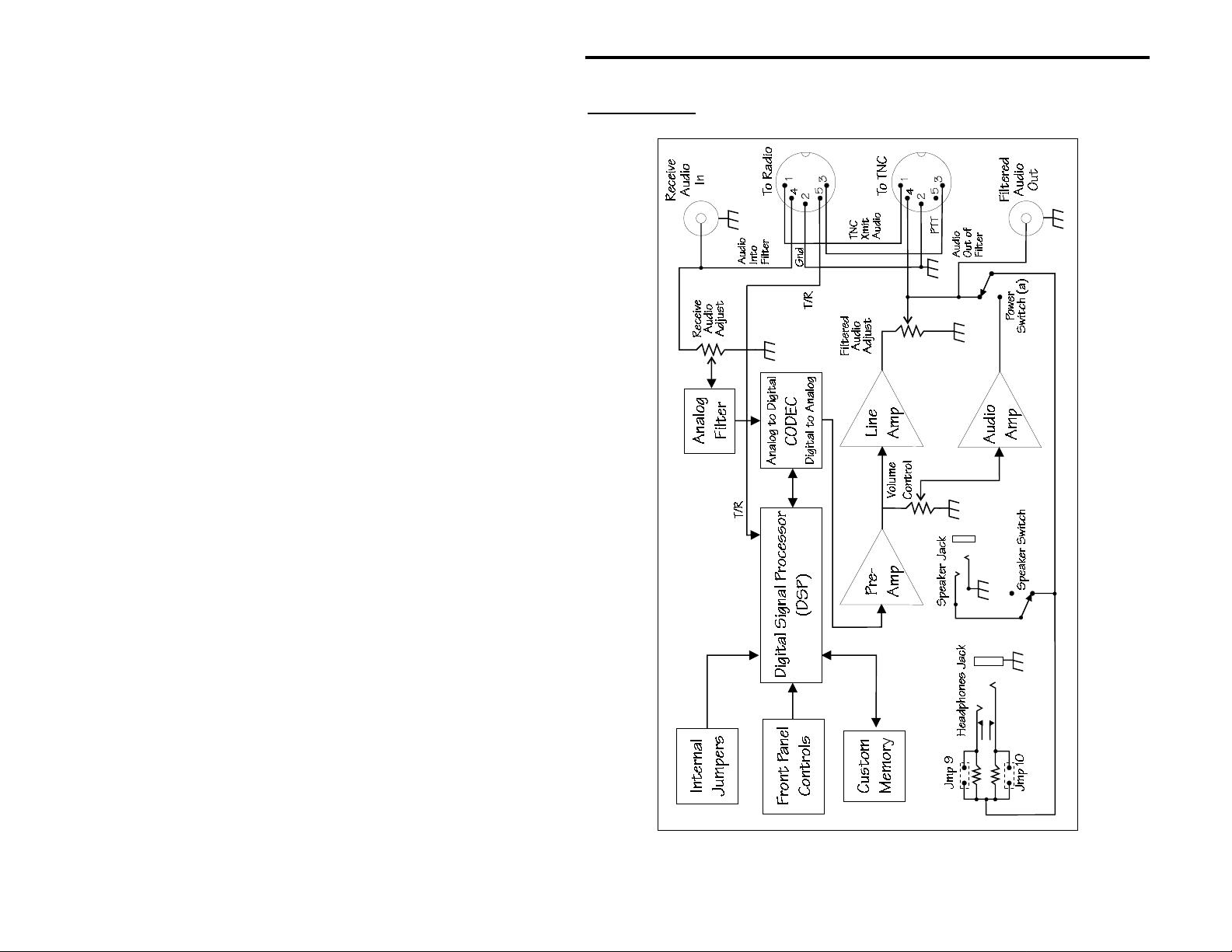
Block Diagram
Introduction Error! Main Document Only.-4
Page 13

VEC-884 Owner's Manual
Front Panel Layout
AGC button: Press to enable the automatic gain control;
press again to turn it off.
Program button: Press to program memory filters, to talk, or to
activate CW spotting tone.
Memory button: Selects either normal or memory filters mode.
Filters switch: Selects one of ten normal or ten memory
filters.
PWR LED: Indicates normal (red) or memory (green) mode.
Input Level LED: Indicates input signal level (red too high, off too
low, green is OK).
Tunable Filters left knob: Adjusts tunable filters and manual notch.
Manual Notch button: Press to enable the manual notch; press again
to turn it off.
Tunable Filters right knob: Adjusts tunable filters and manual notch.
Auto Notch button: Press to enable the automatic notch; press
again to turn it off.
Noise Reduction knob: Controls the level of noise attenuation.
Noise Reduction button: Press to enable the noise reduction; press
again to turn it off.
Volume control: Controls the output volume level to speaker
and headphones jacks.
Speaker button: Press to enable the speaker jack; press again
to turn it off.
DSP button: Press to turn on digital processing of input
signal; press again to bypass processing.
Power button: Press to turn the power on; press again to
turn the power off.
For an in-depth description of the front panel controls, refer to Chapter 3,
Operation.
Introduction Error! Main Document Only.-5
Page 14

VEC-884 Owner's Manual
Back Panel Layout
Power: 10-16 Vdc @ .5 amp peak (low "Z " audio load)
Headphones Out: 1/4" stereo or mono phone jack
Speaker Out: 3.5 mm stereo or mono phone jack
Filtered Audio Adjust: screwdriver adjustable potentiometer
Filtered Audio Out: RCA phono jack (~1.5 V P-P @ 600 ohms)
Receive Audio Adjust: screwdriver adjustable potentiometer
Receive Audio In: RCA phono jack
To Radio: 5-pin DIN jack
(TNC xmit audio, ground, PTT, receive audio in,
XMIT/RECEIVE)
To TNC: 5-pin DIN jack
(TNC xmit audio, ground, PTT, filtered audio out)
For an in-depth description of the back panel connections, refer to Chapter
2, Installation.
Introduction Error! Main Document Only.-6
Page 15
VEC-884 Owner's Manual
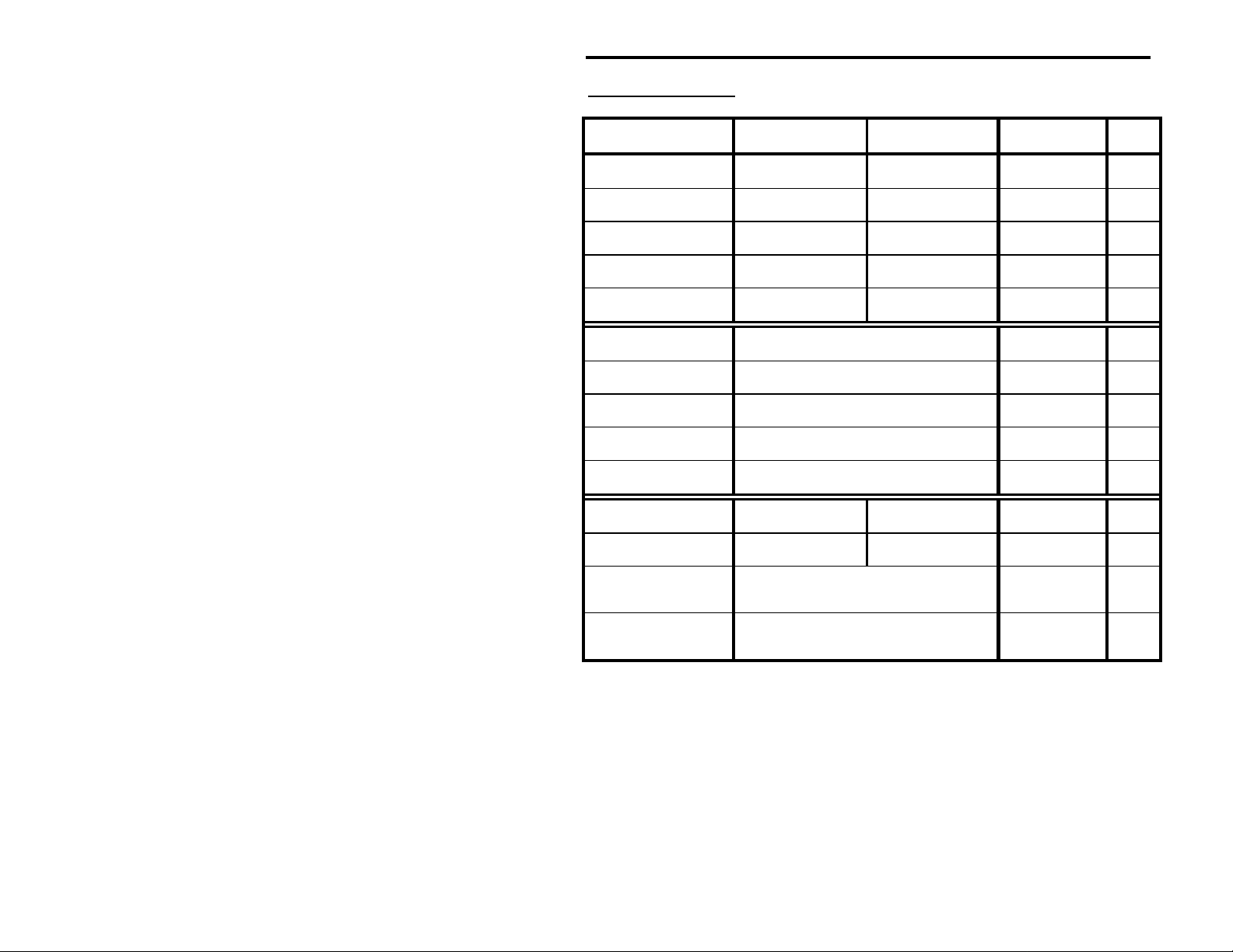
Filter Specifications
Filter Left Control Right Control Attenuation7 Type8
LR/HR1 LR: 200-2200 Hz HR: 1400-3400 Hz 57 dB @ 75 Hz FIR
BP fc: 300-3400 Hz BW: 30-2100 Hz 47 dB @ 60 Hz FIR
2BP2 f1: 300-3400 Hz f2: 300-3400 Hz 47 dB @ 60 Hz F IR
CW3 fc: 300-1000 Hz BW: 30- 700 Hz 47 dB @ 60 Hz FI R
SSB4 fc: 600-1700 Hz BW:1000-2500 Hz 57 dB @ 75 Hz FIR
RTTY Jumper Programmable 47 dB @ 60 Hz FIR
HF PACKET Jumper Programmable 47 dB @ 60 Hz FIR
AMTOR Jumper Programmable 47 dB @ 60 Hz FIR
PACTOR Jumper Programmable 47 dB @ 60 Hz FIR
SSTV/FAX/WeFAX Fixed @1050-1350 Hz an d 1450-2350 Hz 45 dB @ 60 Hz FIR
Manual Notch f1: 150-3400 Hz f2: 150-3400 Hz 40 dB @ 95 Hz IIR
Manual Notch (CW mode) f1: 300-1000 Hz f2: 300-1000 Hz 40 dB @ 105 Hz IIR
Multiple Automatic
Notch5
Random Noise
Reduction6
Note 1: The
Note 2: The
Note 3: The CW filter has an optional jumper-programmable sidetone filter.
Note 4: The
Note 5: The multiple automatic notch has four jumper-programmable levels of aggressiveness and
Note 6: The random noise reduction has a variable level of noise reduction.
Note 7: All FIR and II R filter attenuation is indicated in dB @ a distance in Hz outside the pas sband. All LMS
Note 8: All FIR filters are linear phase with a 23 mS time delay and have the upper cutoff frequency limited
FIR - Finite Impulse Response IIR - Infinite Impulse Response LMS - Least Mean Square
LR/HR
all-pass filter when LR is adjusted equal to HR.
the two center frequencies.
capable of eliminatin g up t o four changing tones or heterodynes.
filter attenuation is dependent on the characteristics of the noise.
to 3900 Hz.
filter becomes a band-stop filter when LR is adjusted higher than HR or becomes an
2BP
filter uses the bandwidth setting last used in BP filter but allows indepe nde nt vari atio n of
SSB
filter has its lower cutoff frequency limited to 175 Hz.
Entire freq. range of the received audio Up to 50 dB LMS
Entire freq. range of selected band-pass filter Up to 20 dB LMS
Introduction Error! Main Document Only.-7
Page 16

VEC-884 Owner's Manual
Introduction Error! Main Document Only.-8
Page 17
VEC-884 Owner's Manual
Unit Specifications
General Specifications
Processor
: Analog Devices ADSP-2105. Data width - 16 bits. Clock speed -
12 MHz.
Bypass
: The VEC-884 DSP filter has a direct audio bypass when power switch
is in "off" position.
Input/Output Specifications
: The maximum curr ent demand will be less than 500 mA at maximum
Power
volume but will always be more than 175 mA.
Filtered Audio Out
: This jack provides approximately 1.5 volts P-P into 600
ohm (or higher) impedance loads (160 mW @ 6 ohms). The output
voltage of this jack is dependent on Filtered Audio Adjust.
Receive Audio In
: This jack should be driven in a range of 1 to 2.8 volts P-P
when Receive Audio Adjust is set to maximum sensitivity. When
Receive Audio Adjust is set to minimum sensitivity, the DSP requires a
very high input voltage. Input circuit loading is 10 K ohms nominal.
Audio Output
: Audio output power is ≈2.5 watts into a 6 ohm load with the AC12 power supply. Au dio frequency r esponse is fro m 250 to 3100 Hz
(-3 dB).
Introduction Error! Main Document Only.-9
Page 18

Page 19

VEC-884 Owner's Manual
Installation
Contents of This Chapter
Back Panel Connections Page 2-2
>
Basic Connections Page 2-3
>
Setting Receive Audio Level (Input Level) Page 2-4
Increasing Headphone Audio Level Page 2-4
Passing Sidetone Page 2-5
>
XMIT/RECEIVE Connection Page 2-5
CW Sidetone Filter Page 2-6
DSP to TNC Connections Page 2-6
>
2
Installation Error! Main Document Only.-1
Page 20
VEC-884 Owner's Manual
Back Panel Connections
: This connector supplies power to the unit. It connects to a 2.1 mm
Power
coaxial plug with the center conductor positive and the shield ground. An
optional dc supply, the AC-12, is available from Vectronics. The voltage
should be 10-16 Vdc.
the VEC-884 will perform erratically.
Warning:
V
If the power supply voltage drops below 10 volts
oltages greater than 18 volts or reverse polarity may
permanently damage the VEC-884.
Headphones Out: This jack supplies volume controlled audio for headphones. It
accepts standard male 1/4 inch stereo or mono phone plugs and
provides audio to both stereo and mono headphones.
Speaker Out: This jack supplies volume controlled audio for a speaker or
walkman type headphones with 3.5 mm stereo or mono phone plugs.
Disengaging the Speaker button disables this jack.
Filtered Audio Adjust: This adjustment varies the level of the audio outputs to
Filtered Audio Out and pin 4 of the To TNC port.
Filtered Audio Out: This jack supplies line level audio for tape recorders or
audio amps. It is a standard RCA phono jack. A quality shielded cable
should be used for connections to this jack. The output is dependent on
the Filtered Audio Adjust and independent of the DSP's volume control.
Receive Audio Adjust: This adjustment controls the sensitivity of the Receive
Audio In jack and pin 4 of the To Radio port. Proper adjustment is
achieved if the Input Level indicator flashes mostly green and never red
when the receiver's volume is at normal levels. Refer to page 2-4.
Receive Audio In: This jack is normally connected to the receiver's speaker or
headphones output. It is a standard RCA phono jack. A shielded cable
should be used to connect this connector to the station receiver.
To Radio: This port supplies connections for transmit and receive audio. PTT is
connected directly to the To TNC port. A connection is also available for
a XMIT/RECEIVE line to automatically bypass the filter during transmit.
To TNC: This port supplies connections to the filtered audio output and the
transmit audio inputs. PTT is connected directly to the To Radio port.
Installation Error! Main Document Only.-2
Page 21

VEC-884 Owner's Manual
Basic Connections
In the most simple case, the VEC-884 will be installed in the audio path
between your receiver and your headphones or speaker.
Installation Error! Main Document Only.-3
Page 22
VEC-884 Owner's Manual
Setting Receive Audio Level (Input Level)
When first connecting the DSP filter and whenever the receiver audio level
changes, you should check the Input Level indicator. This LED indicates the
input signal level. As a signal is received, the Input Level LED will flash from
"off" to either green or red.
If the indicator flashes:
Mostly Green (never red) the input level is adjusted correctly.
Any Red the input level is too high.
Stays Off (or barely green) the input level is too low.
To set Receive Audio Adjust:
1. Tune your radio to the type of signal you will be operating most.
2. Set your
3. Use a screwdriver to adjust the Receive Audio Adjust ( on the back p anel
of the DSP) until the Input Level LED (on the front panel) flashes mostly
green and never red.
Note:
radio's
Some compromise may be required if the receiver does not maintain
volume control to a normal level.
the same audio level on different modes. Set the Receive Audio
Adjust on the DSP for the most common mode, and use the receiver's
volume knob to properly adjust the level when switching modes.
Increasing Headphone Audio Level
The VEC-884 headphone level is attenuated as it comes from the factory. If a
speaker is at a comfortable level and the headphones are too quiet, the level
may be raised by using jumpers JMP 9 and JMP 10 (next to the headphones
jack).
Warning: Do not short JMP 10 when using a mono phone plug or
damage to your unit will result.
To raise the headphone audio level fo r mono headphones, put a 470 ohm or
smaller resistor on JMP 9. For stereo headphones, put
smaller resistor on JMP 10.
Installation Error! Main Document Only.-4
another
470 ohm or
Page 23
VEC-884 Owner's Manual
Passing Sidetone
Operators may listen to a station tone with different pitch than the sidetone of
their transmitter. In this situation, the DSP filter will attenuate the sidetone
and the operator will not be able to monitor his sending. There are two
methods of passing sidetone through the DSP filter.
XMIT/RECEIVE Connection
preferred
The
(transmit/receive) line on the DSP's To Radio port. All filter functions are
bypassed when the XMIT/RECEIVE line is pulled low. The transceiver's
sidetone and audio monitoring functions will appear at the DSP output without
digital filtering.
The XMIT/RECEIVE line should be connected to an output from your radio
that is pulled low when the radio goes into the transmit mode (such as an
output for an external RF amplifier). Radio manufacturers call such a line
many different names: Relay or RLY; NO or normally open; xmit, transmit or
send; or maybe even PTT.
If a linear amplifier is connected to the XMIT/RECEIVE line, a diode (1N4001
or equivalent) should be connected from the linear amplifier's control (relay)
jack to the XMIT/RECEIVE line. This diode prevents the amplifier fr om loading
the DSP's XMIT/RECEIVE line when the amplifier is turned "off." The anode of
the diode should be connected to the amplifier and the catho de (banded end)
to the XMIT/RECEIVE line.
method for passing sidetone is the use of the XMIT/RECEIVE
Warning: Never connect the
XMIT/RECEIVE
line to negative
voltages or to positive voltage sources that exceed 35 volts.
The DSP has internal protection circuitry to help prevent other equipment
connected to the XMIT/RECEIVE line (such as a linear amplifier) from
damaging the unit.
Installation Error! Main Document Only.-5
Page 24
VEC-884 Owner's Manual
CW Sidetone Filter
less preferred
The
method for passing sidetone involves programming a
special internal CW sidetone filter. The CW sidetone filter is a totally separate,
jumper programmed, constant frequency filter. This option makes the DSP
function with two separate parallel filter s. One filter is the standard adjustable
CW filter and the other is the fixed frequency CW sidetone filter. This method
has the advantage of not requiring a XMIT/RECEIVE connection, but the
disadvantage of allowing unwanted signals to feed through if they happen to be
within 30 Hz of the sidetone frequency. To enable the CW sidetone filter,
internal jumpers must be set to the sidetone frequency of your radio. Refer to
page 4-10 for a description of setting the sidetone filter. The center frequency
of the sidetone filter ranges from 300 Hz to 1000 Hz in 50 Hz increments.
The bandwidth of the sidetone filter is fixed at 50 Hz.
DSP to TNC Connections
When connecting to a TNC, Vectronics suggests the use of the 5-pin ports.
TNCs need a PTT connection that is only available on these ports.
The VEC-884 plugs directly into any Vectronics/MFJ/TAPR2 compatible TNC.
Use a 5-pin DIN-to-5-pin DIN cable, MFJ-5100, for connection to
Vectronics/MFJ/TAPR2 compatible TNCs or the PK-12/96/900. MFJ
offers pre-wired radio cables (models MFJ-50xx) for connection to your radio
and pre-wired TNC cables (models MFJ-51xx) for connection to other TNCs.
Refer to the appendix for more information on these radio-to-TNC cables.
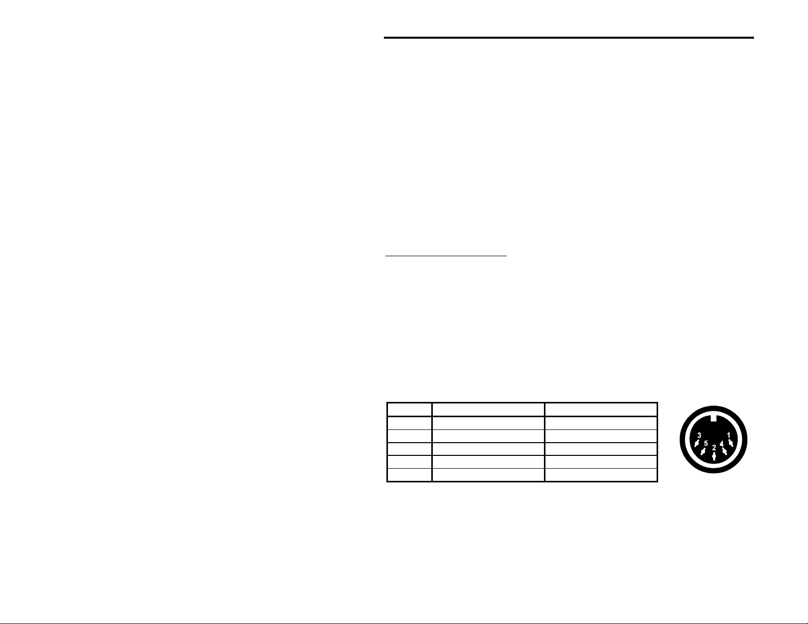
Pin To Radio Function To TNC Function
1 TNC Xmit Audio TNC Xmit Audio
2 Ground Ground
3 PTT PTT
4 Receive Audio In Filtered Audio Out
5 XMIT/RECEIVE No Connection
Installation Error! Main Document Only.-6
Page 25

VEC-884 Owner's Manual
Installation Error! Main Document Only.-7
Page 26

Page 27

VEC-884 Owner's Manual
Operation
Contents of This Chapter
Initial Operation Page 3-2
>
CW Operation Page 3-3
SSB (and other voice modes) Operation Page 3-4
Front Panel Description Page 3-6
>
PWR LED Page 3-6
Input Level LED Page 3-6
AGC Button Page 3-7
Program Button Page 3-7
Memory Button Page 3-8
Filters Switch Page 3-8
Tunable Filters Controls Page 3-9
Manual Notch Button Page 3-10
Auto Notch Button Page 3-11
Noise Reduction Control Page 3-12
Noise Reduction Button Page 3-12
Volume Control Page 3-12
Speaker Button Page 3-12
DSP Button Page 3-13
Power Button Page 3-13
3
Operation Error! Main Document Only.-1
Page 28
VEC-884 Owner's Manual
Initial Operation
Connect the VEC-884 as outlined in Chapter 2. To prepare the unit, set the
controls as follows:
Control Position Meaning
AGC button: out AGC off
Program button: N/A N/A
Memory button: out (normal) Tunable/Pre-Set mode
Filters switch: CW CW filter
Tunable Filters left knob: center middle center freq.
Manual Notch button: out manual notch off
Tunable Filters right knob: full counter-clockwise maximum bandwidth
Auto Notch button: out auto notch off
Noise Reduction control: full counter-clockwise minimum reduction
Noise Reduction button: out noise reduction off
Volume control: full counter-clockwise minimum volume
Speaker button: in speaker on
DSP button: out DSP bypassed
Power button: out VEC-884 off
Warning: Damage or improper operation may occur if the
polarity, current or voltage of the supply is incorrect. See the
installation section on page 2-2. Please don't assume your power
supply wiring is correct.
The external power supply should be connected and on. The headphones
and/or speaker should be connected to the correct jacks.
Turn the power on by pressing the DSP's Power button. The PWR LED will
red
glow
microprocessor is operating. This LED will glow
are selected. Press and release the Memory button if this LED is green.
. The red glow indicates the normal filter mode is selected and the
green
if the memory filters
Operation Error! Main Document Only.-2
Page 29

VEC-884 Owner's Manual
CW Operation
This example will demonstr ate how the CW filter operates and show you how
to adjust the audio level from the statio n's receiver for proper DSP operation.
If your receiver doesn't operate CW you can skip to the SSB section. That
section works for AM, FM, and SSB.
Before attempting to operate your VEC-884, you must familiarize yourself with
the DSP controls (be sure yo u have read the preceding sections). Your VEC884 should be set up as outlined in the initial operation section on the
preceding page. Tune in a CW station and adjust your receiver for normal
comfortable levels of pitch and volume.
Next, push and lock the DSP button "in." Adjust the DSP's Volume control to a
comfortable setting. Make sure the left Tunable Filters control is centered,
and the right control is fully counter-clockwise.
Note:
Always use the DSP's volume control to adjust the volume when the
DSP is "on." Never adjust the receiver's volume knob to control the
volume unless the DSP's power is "off."
1. Look at the Input Level LED. If it flashes or lights red, you will have to
decrease the receiver's volume control or adjust the Receive Audio
Adjust control on the DSP's back panel towards MIN. If the Input Level
LED is flashing or steadily green the audio level is acceptable. The ideal
setting is where the LED is as green as possible without ever turning red.
(Refer to page 2-4 for a longer explanation.)
2. Press and hold the red Program button. You will hear a tone. Adjust the
left Tunable Filters control (center frequency or fc) until the tone is the
same pitch as the CW station. When the tones are closely matched,
release the button.
3. Slowly adjust the right Tunable Filters control (bandwidth or BW)
clockwise. This will increase the selectivity. The desired signal should
become clearer (less noise and QRM) as the right control is moved
clockwise. If turning this control makes the desired signal disappear, the
left Tunable Filters control (fc) will have to be re-adjusted.
Please go through steps 2 and 3 several times to get a feel for how the
controls act. You will notice tuning becomes more touchy as the BW
(bandwidth) control is decreased, but the signal becomes clearer. With a little
practice you will become very good at adjusting the filter.
Operation Error! Main Document Only.-3
Page 30

VEC-884 Owner's Manual
4. Place the DSP button in the "out" position. Tune your receiver until a
frequency is found with several CW signals sending at the same time.
When the digital processing is activated by pressing the DSP button "in,"
you should be able to separate the signals with the Tunable Filters
controls. Careful adjustments to the DSP filter's center frequency (with
moderate or low bandwidth) may even allow you to copy signals that were
undetectable without the filter.
5. Take some time to experiment with the Noise Reduction, AGC, Man ual
Notch, and the Tunable Filters controls in the CW mode. For the best
use of this filter, you should become familiar with the effects of all these
controls.
Note:
Most people monitor their sending with a transmitter sidetone
oscillator. If you use this common method of monitoring yourself, you
have to program a sidetone filter or ground the XMIT/RECEIVE line to
monitor yourself. Page 2-5 gives details on this requirement.
SSB (and other voice modes) Operation
The example in this section demons trates the basic SSB filter functions, and
allows for further confirmation of the station receiver audio level adjustments.
Turn the DSP's Filters switch to SSB mode and place the AGC and NOISE
REDUCTION buttons out ("off"). Place the DSP button in the "out" position.
Tune in a SSB, AM or FM station and adjust your radio for normal pitch and
volume. Press and lock the DSP button "in." Adjust the Volume control on the
DSP to a comfortable volume setting.
Note:
Always use the DSP's volume control to adjust the volume when the
DSP is "on" unless specifically told otherwise.
1. Observe the Input Level LED and adjust audio input if the LED is not fully
green without ever flashing red. The ideal adjustment point is when the
LED is as green as possible withou t ever flashing red. If the LED is red,
reduce the receiver's volume control; if the LED is not lit, increase the
receiver's volume control. (Refer to page 2-4.)
2. Adjust the left Tunable Filters control (center frequency or fc) and the
right Tunable Filters control (bandwidth or BW) to peak the SSB signal
for maximum intelligibility.
Operation Error! Main Document Only.-4
Page 31

VEC-884 Owner's Manual
3. You should notice the signal becomes clearer (less noise and QRM) as
the bandwidth (right Tunable Filters control) is moved clockwise and the
center frequency (left Tunable Filters control) is re-adjusted. At some
point decreasing the bandwidth will make the signal less intelligible. If this
happens turn the right Tunable Filters control counter-clockwise.
4. Place the DSP button in the "out" position. Adjust the receiver until you
find a frequency that has CW or any other tone interference audible with
a SSB or voice signal.
5. Place the DSP button in the "in" position. Lock the Auto Notch button "in."
The interference should disappear or be greatly reduced.
Note:
The automatic notch will not recognize signals that vary rapidly in
frequency or amplitude, becau se the filter mus t ignore ra pid amplitude
and frequency changes to avoid nulling or distorting voices. If the
automatic notch distorts voice reduce the radio volume slightly or
select a less aggressive internal auto notch jumper.
6. Experiment with different filter adjustments and functions under various
conditions to become familiar with the various controls.
Operation Error! Main Document Only.-5
Page 32

VEC-884 Owner's Manual
Front Panel Description
The following section will help you become familiar with the operation of the
DSP. The two L EDs are explained first. The buttons, switch, and contr ols are
then explained from left to right as they appear on the panel.
PWR LED
This LED lights two different colors, red and green. It helps tell you when the
DSP is on and working, and whether the DSP is using the memory or the
normal Tunable/Pre-Set filters.
When you turn the DSP power o n, there will be a s light delay and this LED will
light. If this LED lights red, the Tunable/Pre-Set filters are being used.
If this LED is green, the memory filters (called Memory) that you can store or
program are being used. We explain this in detail as we talk about operating
the DSP.
If this LED does not light, or does not change color when the Memory button is
changed, the DSP is not operating correctly.
Input Level LED
This LED lights two different colors, red and green. It tells you if the DSP is
getting the correct audio level from the receiver.
The volume of the audio from your receiver will change with different signals.
Please remember that sometimes there may be a lot of receiver audio, and
sometimes there may not. For example, the station you are listening to will
probably not be sending all the time, or may be fading in and out.
Operation Error! Main Document Only.-6
Page 33

VEC-884 Owner's Manual
The use of this LED is very simple. When you are listening to a loud signal,
adjust the receiver's volume control so the LED lights the most steady and
brightest green possible witho ut ever going red. If the LED doesn't light green
on good signals, the receiver volume is too low for the best filter performance.
With a properly designed receiver that has a good AGC circuit, you won't have
to adjust the receiver volume control very often. You will only have to adjust it
when (or if) the Input Level LED indicates improper level by flashing red or
failing to light an almost steady green color.
AGC Button
This button controls an automatic gain control (AGC) program. The AGC
program automatically adjusts the DSP's internal gain. It tries to make all
signals have exactly the same volume. The AGC button setting cannot be
stored in memory. It operates independently of all other buttons and controls
except the DSP and the Power buttons.
The AGC is activated by pushing and locking this button "in." If the DSP is on
and operating, pushing the AGC button "in" will make every s ignal have nearly
the same volume level, if the input signal level changes less than 18 dB.
If there is a lot of noise on the signal, you may not want to use the AGC
function. It will increase the volume of the noise during long pauses in the
signal you are listening to. That can distract you or make it difficult to
concentrate on the signal you are listening to.
Program Button
This button is used to make the DSP memorize the filter settings you are
currently using. When using the tunable CW filter, this button activates the
CW spotting tone. It also starts a "Talk" feature if the DSP button is "out." This
button does not stay locked-in like the other buttons, it springs right back out
when released.
The use of this button is very special. To use this button to memorize or save
a filter, please read the section on page 4-2. To use this button to activate the
spotting tone, please read the section on page 4-4. To use this button to start
the Talk feature, please read the section on page 4-5.
Operation Error! Main Document Only.-7
Page 34

VEC-884 Owner's Manual
Memory Button
This button allows you to choose two different groups of filters with the Filters
switch. This button functions any time the DSP's power is on and the DSP
button is "in."
With the Memory button "out," the Filters switch picks one of ten Tunable
(front panel adjustable) and Pre-Set (jumper or factory programmed) filters
marked LR/HR through SSTV/FAX/WeFAX.
When the Memory button is "in," the Filters switch picks a memory location
labeled 1 through 10 on the front panel. The DSP processes the signal using
the filter you have stored in that memory location. Page 4-2 gives you more
detail on the use of memory.
Filters Switch
This switch picks the main filter used to process the signal. It is used in
conjunction with the Memory button we talked about above. It functions
whenever the DSP power is on and the DSP button is "in."
Note:
Please remember that when we say Tunable, the main filter's
bandwidth and frequencies can be adjusted by the two front panel
Tunable Filters controls. Pre-Set means the front panel Tunable
Filters controls cannot be used to adjust the filter. A Pre-Set filter's
mark-space frequencies and bandwidth can only be changed by
removing the cover and re-programming internal jumpers (see page 4-
11).
When the Memory button is "out," the Filters switch selects one of the 5
Tunable filters (LR/HR, BP, 2BP, CW, and SSB) or one of the 5 Pre-Set filters
(RTTY, HF PACKET, AMTOR, PACTOR, and SSTV/FAX/WeFAX).
When the Memory button is "in," the Filters switch selects any one of ten
memory filters you have stored in locations 1 through 10 of the DSP's
memory. The Filters switch also selects the memory position (1-10) where you
can store the last Tunable/Pre-Set filter you're using.
Chapter 5, Filter Description, gives more detailed information on each filter
type available with this switch. Chapter 4, Advanced Features, gives more
details on using the memory.
Operation Error! Main Document Only.-8
Page 35

VEC-884 Owner's Manual
Tunable Filters Controls
The Tunable Filters knobs, left and right, adjust the center frequency (also
called the tone or pitch) and the bandwidth (also called the selectivity ) or the
lower and upper cutoff frequencies of the 5 Tunable filters selected by the
Filters switch. These filters are the LR/HR, BP, 2BP, CW and SSB filters.
These controls also adjust the two manual notch frequencies whenever the
Manual Notch button is "in."
Note:
The manual notch function uses the same controls as the main filter.
That means any time the manual notch is being used, the adjustable
filter cannot be changed.
The following chart tells you what type of adjustment is made by the left and
right Tunable Filters controls in every front panel adjustable filter position.
Mode Tunable Filters Left Tunable Filters Right
LR/HR
BP
2BP
*
CW
SSB
Manual Notch
* The 2BP's bandwidth (or selectivity) is changed by adjusting the BP's
bandwidth before selecting 2BP.
lowest freq. you will hear highest freq. you will hear
center frequency bandwidth *
center frequency 1 center frequency 2
center frequency bandwidth
center frequency bandwidth
notch frequency 1 notch frequency 2
Operation Error! Main Document Only.-9
Page 36

VEC-884 Owner's Manual
Manual Notch Button
When pressed in, this button activates two manually adjustable notch filters.
Each filter rem oves a very narrow range of freq uencies or tones. The manual
notch operates in every filter mode except when the DSP button is out.
The manual notch is often used to notch out one or two unwanted tones on
CW, voice or digital modes. A manually adjusted notch is the only type of notch
that operates correctly on CW and digital modes. The manual notch can also
remove warbling or buzzing carriers that the automatic notch may ignore. The
manual notch also causes less audio distortion in voice modes than an
automatic notch.
A manual notch does some things better than the automatic notch. In tone
modulated modes the automatic notch wouldn't "know" which tone you wanted
to hear and which tone was the interference. It would remove the good signals
right along with the bad signals. Since the operator can tell which tones are
bad, he/she can use the manual notch to remove them.
The Tunable Filters left and right knobs adjust the frequency of each notch
over the entire audio range of the filter . The manual notch bandwidth is very
narrow. Tones w ithin 100 Hz o f each no tch fr equenc y will be r educ ed over ten
thousand times in volume. If you only need to notch one tone, set the other
Tunable Filters control to any end of its range. Doing so will prevent the
unused notch from hurting the quality of the signal you want to hear.
One thing is a little tricky when using the manual notch. Since the manual notch
uses the Tunable Filters left and right knobs to adjust the notch frequencies,
you must select and adjust the correct main filter
before
using the manual
notch. The VEC-884 always "remembers" the Tunable Filters left and right
knobs settings when the manual notch is engaged and then the Tunable
Filters left and right knobs will only adjust the two manual notch frequencies.
Another important thing to remember is when you release the Manual Notch
button, the main filter will still remain exactly as it was set. The only thing that
will happen is the notch will turn off. But if you adjust or move either Tunable
Filters left or right knob, the main filter will quickly jump to the current control
settings. If you don't want to loose your original filter settings, don't touch the
Tunable Filters left or right knobs after using the manual notch. You can
adjust and use the notch as much as you like without affecting the original filter
settings whenever the Manual Notch button is "in."
Operation Error! Main Document Only.-10
Page 37

VEC-884 Owner's Manual
Auto Notch Button
The auto notch does nearly the same job as the manual notch except it finds
and removes up to four u nwanted tones very effectively. The main advantage
of the auto notch is that it hunts down and removes steady tones without any
help from you. The auto notch operates
only in
the LR/HR, BP, 2BP, and SSB
filters regardless of whether they are saved in memory or not.
With the Auto Notch button "in," the VEC-884 searches for heterodynes or
steady tones and instantly removes them. It is so good it can remove four
drifting tones at the same time, even if the tones are moving in different
directions.
The automatic
notch filter has two important limitations. First, it cannot tell the
difference between a good tone and a bad tone. Some Filter positions are
used for receiving tone signals and the auto notch wouldn't have any idea
which tone you really want to copy. Therefore, we can't let you use the auto
notch in the following Filters switch positions: CW, RTTY, HF PACKET, AMTOR,
PACTOR, and SSTV/FAX/WeFAX. In these modes the auto notch would
remove every signal, not just the bad ones.
Second, the automatic notch cannot tell the difference between a voice and a
tone that varies rapidly in volume and pitch. If we made the automatic notch
remove all the very fast changing tones, it would also remove tones from
voices. If we made the automatic notch work only on the slowest changing
tones, it would not follow the drifting or fading tones you didn't want to hear.
Because of this limited operating range, we give you two ways to select how
quickly and completely the automatic notch works.
One way you can co ntrol the no tch speed is by reduc ing the volume contro l on
your receiver slightly. This will lower any distortion on voices while the
automatic notch is being used.
The second way to adjust the automatic notch involves removing the DSP's
cover and moving two jumpers to different positions. This adjustment allows
you to choose four different levels of what we call auto notch aggressiveness.
We ship the DSP in the least aggressive setting (1). If you are unhappy with the
notch and would like to step the notch performance up a little bit, you can
reset the jumpers. Refer to Jumper Settings on page 4-8. Remember that the
automatic notch's distortion of voices will get worse if you choose a more
aggressive setting.
Operation Error! Main Document Only.-11
Page 38

VEC-884 Owner's Manual
Noise Reduction Control
This knob controls how much the noise reduction program reduces random
noises. Random noises are noises that do not repeat at exactly the same rate.
When this control is in the full clockwis e position, random nois es are reduced
the maximum amount possible. This control's setting can be used in any active
filter mode, including while the Memory button is "in."
Remember to use the least amount of noise reduction necessary. Turning the
Noise Reduction control up too far (clockwise) will reduce the audio and cause
unnecessary audio distortion and echo. This is an unavoidable side effect of
noise reduction at audio fr equencies. The slight echo or hollowness in voices
occurs from time delays in the filter and the noise reduction program's effect
on random peaks in voices.
Turning off the AGC on the DSP may also reduce how much unwanted noise
bothers you.
Noise Reduction Button
This button turns the noise reduction filter on or off. The Noise Reduction
button operates in every filter mode, including the memory positions.
Volume Control
The Volume control adjusts the audio level at the Headphones Out and the
not
Speaker Out jacks. It does
adjust the audio output level at the Filtered
Audio Out and To TNC output ports. The Filtered Audio Out has a back panel
screwdriver adjustment. This control's position cannot be stored in memory,
and it operates all the time. See the block diagram on page Error! Bookmark
not defined.-4.
Speaker Button
This button turns the external speaker on or off. It operates in any position of
the Memory button and in every mode as long as the Power button is on.
Operation Error! Main Document Only.-12
Page 39

VEC-884 Owner's Manual
DSP Button
While "in" this button causes the DSP to digitally process the signal. While
"out" this button prevents the DSP from doing any digital processing. It
operates in any position of the Memory button.
Non-processed audio is still available at all the audio outputs when this button
is in the out position. The only change is the audio output voltage at all the
jacks, including the Filtered Audio Out jack, is no longer held constant. The
Volume control still functions with the headphones and speaker while the DSP
button is "out."
Power Button
This button controls the power to the DSP. It operates in any position of the
Memory button.
When the Power button is off (out), this switch connects all the input ports to
the speaker and headphones outputs. The F ilter e d Au dio O u t jac k and the To
TNC port become "dead." See the block diagram on page 1-4.
Do not use this switch to bypass the DSP. Use the DSP button. You should
only use this switch to turn the DSP off after you are completely finished using
the DSP.
Operation Error! Main Document Only.-13
Page 40

Page 41

VEC-884 Owner's Manual
Advanced Features
Contents of This Chapter
Memory Filters Page 4-2
>
Saving Memory Filters Page 4-2
CW Spotting Tone Page 4-4
>
Measuring Frequency Page 4-4
Talk Page 4-5
>
Talk Operation Page 4-5
Jumper Settings Page 4-8
>
Talk Settings Page 4-8
Auto Notch Aggressiveness Page 4-8
Normal Jumper Settings Page 4-8
Normal Jumper Settings Chart Page 4-9
Setting the CW Sidetone Filter Page 4-10
Pre-Set Filters Page 4-11
Data Mode Jumper Settings Chart Page 4-12
4
Advanced Features Error! Main Document Only.-1
Page 42

VEC-884 Owner's Manual
Memory Filters
The VEC-884 allows you to save your favorite filter settings into one of ten
"memory filters" in non-volatile memo ry. Whenever you have to r epeatedly set
your DSP filter for one station or for similar operating conditions, you may
choose to save the settings in memory.
Each position of the Filters switch can select a memory filter for a total of ten
filters. These filters are selected when the Memory button is in.
The memory filters store the Filters s witch's Tunable/Pre-Set filter selection
and the corresponding filter's center frequency and bandwidth or lower and
upper cutoff frequencies, including the CW sidetone filter if set and enabled.
The center frequency and bandwidth or low/high reject frequencies of the
filters stored in memory cannot be adjusted. Only the noise reduction and
notch filters can be adjusted while using a memory filter (Memory button in).
If you use several different mark-space frequencies, program and save several
filters at once. Otherwise you may have to take the cover of the unit off several
times. Save a memory filter with each mark-space frequency that you will be
using. For programming mark-space frequencies refer to page 4-11.
erase
It is not necessa r y t o
an old memory filter. Old filters are erased when a
new filter is saved over them. Use the chart on page A-7 to record your
memory filters settings.
Saving Memory Filters
1. With the Memory button out, select and adjust the filter that you want to
save.
Advanced Features Error! Main Document Only.-2
Page 43

VEC-884 Owner's Manual
2. Press and lock the Memory button in. The PWR LED will now turn green,
indicating the memory filters, and your new filter settings will be saved
temporarily until they are saved into a memory position (1-10).
Note:
From steps 2-4 your filter may not appear to work because the filter
position (1-10) is still set to the old memory filter.
3. Turn the Filters switch to the position where the new filter is to be saved.
red
4. Press and hold the Program button. The LEDs will light
will beep in one second. Release the Program button. This memory
position will now operate with these settings whenever memory mode is
selected (Memory button in).
and the DSP
Advanced Features Error! Main Document Only.-3
Page 44

VEC-884 Owner's Manual
CW Spotting Tone
To help you find the center frequency for the CW filter, the VEC-884 is
equipped with a CW spotting tone. The spotting tone marks the center
frequency of the tunable CW filter and appears when the Program button is
pushed in while the DSP button is in. While the spotting tone is present, the
bandwidth of the CW filter is opened to maximum allowing you to "zero in" on
any CW signal from 300 Hz to 1000 Hz.
As the spotting tone pitch, adjusted with the Tunable Filters left knob, gets
close to matching the incoming CW signal's tone, you will hear a beat note.
This note will decrease in pitch until a very slow waver or fade is heard in the
signals. When this wavering is adjusted to the slowest rate, the center
frequency of the CW filter matches the incoming CW signal.
To use the CW spotting tone:
1. Select the CW Filter. The Filters switch must be turned to CW and the
Memory button must be out.
2. Engage the filter by pressing and locking the DSP button in.
3. Press and hold the Program button to activate the spotting tone.
4. Use the Tunable Filters left knob to zero-beat (match) the spotting tone
and the CW signal.
5. Release the Program button.
6. Decrease the bandwidth with the Tunable Filters right knob to eliminate
all other signals.
Measuring Frequency
By using the spotting tone, you can measure the approximate frequency of any
audio tone between 300 Hz and 1000 Hz.
1. Disengage the DSP button out to bypass the filter.
2. Select the CW Filter. The Filters switch must be turned to CW and the
Memory button must be out.
3. Engage the filter by pressing and locking the DSP button in.
4. Press and hold the Program button to activate the spotting tone.
5. Use the Tunable Filters left knob to zero-beat (match) the spotting tone
and the signal you wish to measure.
6. Release the Program button.
7. Release the DSP button. Press and release the Program button.
CF
8. Copy the CW. The number following
is the signal's approximate
frequency. (You are using Talk. See the Talk section on page 4-5.)
Advanced Features Error! Main Document Only.-4
Page 45

VEC-884 Owner's Manual
Talk
In order to know more about the settings of the various filters, Vectronics has
provided the Talk function. Talk tells you filter settings by sending them over
the audio outputs and by flashing them on the LEDs in Morse code. This
feature is extremely useful if you have forgotten the settings for jumper
programmed memory filters and you do not wish to remove the cover to reprogram them! When used with the CW spotting tone, this feature also
allows you to accurately measure a frequency from 300 Hz to 1000 Hz.
The Talk routine uses the following abbreviations:
CF = C
BW = B
L =
R
= Notch Frequency 2 (Tunable Filters Right Knob)
MN
= Manual Notch
AN
= Automatic Notch
NR
= Noise Reduction
enter Frequency
andWidth
Notch Frequency 1 (Tunable Filters Left Knob)
Talk will send the following settings for a selected Normal or Memory filter:
filter mode (LR/HR, BP, 2BP, CW, SSB, RTTY, etc.),
•
lower and upper cutoff frequencies or center frequency and bandwidth,
•
state of the manual notch and its two notch frequencies,
•
state of the auto notch and its aggressiveness level setting (1-4), and
•
state of the noise reduction filter and its front panel level (1-10).
•
The Talk tone frequency and Morse code speed are jumper programmable.
Factory default speed is 5 words p er minute (WPM) with a 700 Hz pitch. See
Jumper Settings on page 4-8.
Talk Operation
To activate the Talk function:
1. Select a filter using the Filters switch and the Memory button.
2. Set Volume to comfortable listening level.
3. Disengage the DSP button to "out."
4. Press and release the Program button.
5. Listen to the unit send the filter settings (see examples on the next page).
6. At any time, press and lock the DSP button to stop the message.
Advanced Features Error! Main Document Only.-5
Page 46

VEC-884 Owner's Manual
Examples: (These are hypothetical examples.)
Suppose you forget what you stored in memory filter 3. You position the
controls as follows:
Control Position Meaning
Memory button: in select memory filters
Filters switch: 3 (2BP) memory filter 3
Manual Notch button: out manual notch off
Auto Notch button: in auto notch on
Noise Reduction control: midrange reduction level 5
Noise Reduction button: in noise reduction on
Auto Notch aggressiveness: jumper-programmed level 3
Then release the DSP button out, press and release the Program button, and
the VEC-884 sends:
BP CF 1025 BW 350 AN 3 NR 5
You now know that in memory position 3 you have a narrow band-pass filter
with a bandwidth of 350 Hz and center frequenc y of 1025 Hz. The unit also
sent your current settings for notch and noise reduction. Now suppose you
try memory filter 6.
Turn the Filters switch to 6 (RTTY).
Press the Program button and the VEC-884 sends:
RTTY CF 1360 BW 279 NR 5
In this position, you have saved a jumper-programmed RTTY filter with the
center frequency of 1360 Hz and a bandwidth of 279 Hz. These are the
settings for European RTTY. Notice that there is nothing sent for auto notch
because it is disabled in the RTTY filter.
These are examples of the individual filter settings:
LR/HR
High-pass/low-pass (LR < HR):
•
Band-stop filter (LR > HR):
•
All-pass filter (LR = HR):
•
LRHR 2000-3400
LRHR 0-1400 2200-3900
LRHR 0-3900
BP
Normal filter:
•
Limited filter:*
•
BP CF 1500 BW 2100
BP CF 675 BW 1350
Advanced Features Error! Main Document Only.-6
Page 47
VEC-884 Owner's Manual
2BP
Normal filter:
•
Overlapped filter:**
•
2BP CF 300 BW 30 CF 3400 BW 30
2BP CF 1000 BW 100
CW
Filter without sidetone:
•
Filter with CW sidetone:
•
Overlapped filter:**
•
SSB
Normal filter:
•
RTTY
2125-2295 Hz 45 baud:
•
HF PACKET
2125-2295 Hz 300 baud:
•
AMTOR
2125-2295 Hz 100 baud:
•
PACTOR
2125-2295 Hz 200 baud:
•
CW CF 700 BW 30
CW CF 400 BW 50 CF 700 BW 30
CW CF 600 BW 100
SSB CF 900 BW 1000
RTTY CF 2210 BW 250
PCKT CF 2210 BW 504
AMTR CF 2210 BW 304
PCTR CF 2210 BW 404
SSTV/FAX/WeFAX
Non-adjustable:
•
SSTV 1050-1350 1450-2350
Manual Notch
Manual Notch On:
•
(when off, MN is not sent)
MN L 150 R 3400
Automatic Notch
On with aggressive level 3:
•
AN
(when off,
Noise Reduction
On with control midrange:
•
(when off,
is not sent)
NR
is not sent)
AN 3
NR 5
* A filter is "limited" by the VEC-884 frequ ency range of 0-3900 Hz or
175 Hz minimum in SSB. The center frequency and bandwidth for
these filters are changed to reflect these limits. See the Limited Filters
section in Chapter 5.
** An "overlapped" filter occurs when two filters overlap each other
resulting in a single filter capable of passing all the frequencies of the
two filters. See the Overlapped Filters section in Chapter 5.
Advanced Features Error! Main Document Only.-7
Page 48

VEC-884 Owner's Manual
Jumper Settings
Several features of the VEC-884 are varied by internal plug -in jumpers. These
jumpers are used for:
Talk: set CW tone frequency and Morse code speed
Auto Notch: set aggressiveness level
CW sidetone: enable and set sidetone filter
Data modes: program mark-space frequencies and baud rates
Talk Settings
The Talk routine will "tell" you the DSP's filter settings by sending them in
Morse code. Jumpers 1-3 are used for the pitch of the Morse code. Jumpers
4 & 5 are used for the Morse code speed. The DSP is shipped with these
jumpers set at 5 WPM and 700 Hz pitch.
Auto Notch Aggressiveness
We ship the DSP in the least aggressive setting (1). If you are unhappy with
the notch performance and would like to step it up a little bit, you can reset the
jumpers. Remember that the automatic notch's distortion of voices will get
worse if you choose a more aggressive setting.
Normal Jumper Settings
Except when programming CW sidetone and data filters, the jumpers are set
for the Talk routine and the auto notch aggressiveness settings. After
programming a Pre-Set data filter or the CW sidetone filter, the jumpers
should be returned to their original positions for Talk and auto notch.
Warning: Remove all power plug from the VEC-884 before
removing the cover. Even though the unit is "off," power is still
applied to some circuitry.
To set the tone frequency, code speed, and auto notch level:
1. Disengage (turn "off") the Power button and
remove the power plug
.
2. Remove the unit's cover (6 screws).
3. Set the jumpers according to the jumper setting table on the next page.
4. Replace the unit's cover (6 screws).
5. Reconnect the power cable and resume normal operation.
Advanced Features Error! Main Document Only.-8
Page 49

Normal Jumper Settings Chart
JMP 1 JMP 2 JMP 3 Tone
L L L 300 Hz
L L H 400 Hz
L H L 500 Hz
L H H 600 Hz
H L L *
H L H 800 Hz
H H L 900 Hz
H H H 1000 Hz
JMP JMP Code
4
L L *
L H 10 wpm
H L 20 wpm
H H 30 wpm
JMP 6 JMP 7 Auto Notch
L L *
L H 2
H L 3
H H 4
*
This is what the jumpers should look
like for the following settings:
1000 Hz Talk pitch,
10 WPM Talk Morse code speed,
and Auto Notch level 1.
VEC-884 Owner's Manual
Frequency
700 Hz
5 wpm
Level
1
5
Speed
Factory defaults
This is what the jumpers should look like
for the default settings:
700 Hz Talk pitch,
5 WPM Talk Morse code speed,
and Auto Notch level 1.
Advanced Features Error! Main Document Only.-9
Page 50

VEC-884 Owner's Manual
Setting the CW Sidetone Filter
If you do not have a XMIT/RECEIVE connection and wish to pass CW sidetone
through the DSP, you must enable this filter. This is not the preferred method
to pass sidetone, see page 2-5. The CW sidetone filter is a jumper
programmable internal constant frequenc y filter. It only works in the Tunable
CW mode. Any signal within 30 Hz of the sidetone frequency will pass through
this filter.
To enable the CW sidetone filter, program it to the sidetone frequency of your
radio. The center frequency of the sidetone filter ranges from 300 Hz to
1000 Hz in 50 Hz increments. The bandwidt h of the sidetone filter is fixed at
50 Hz. See the chart below for jumper settings.
The DSP unit is shipped with the CW sidetone filter set to "off." If you wish to
disable the filter, program it with all four jumpers in the "H" position.
To set the CW sidetone filter:
1. Disengage the Power button
remove the power plug
and
.
2. Remove the unit's cover.
3. Set the jumpers for the selected
sidetone filter.
4. Turn the Filters switch to CW.
5. Reconnect the power cable.
6. Press and hold the Program
button.
7. Press and lock the Power
button to "on."
8. The unit will beep at the new
sidetone pitch until the
Program button is released.
9. Disengage the Power button
remove the power plug
and
.
10. Set the jumpers back to the Talk
tone frequency a nd Morse co de
speed.
JMP 1 JMP 2 JMP 3 JMP 4 Sidetone
Frequency
L L L L 300 Hz
L L L H 350 Hz
L L H L 400 Hz
L L H H 450 Hz
L H L L 500 Hz
L H L H 550 Hz
L H H L 600 Hz
L H H H 650 Hz
H L L L 700 Hz
H L L H 750 Hz
H L H L 800 Hz
H L H H 850 Hz
H H L L 900 Hz
H H L H 950 Hz
H H H L 1000 Hz
H H H H *
*
Factory programmed
OFF
11. Replace the unit's cover.
12. Reconnect the power cable and resume normal operation.
Advanced Features Error! Main Document Only.-10
Page 51

VEC-884 Owner's Manual
Pre-Set Filters
We have set the RTTY, HF Packet, AMTOR, and PacTOR filters to the most
commonly used mark-space frequencies and baud rates. If you wish to change
from the factory defaults, you must change the jumpers and program a filter.
You may program these filters to a number of mark-space frequencies (shifts)
and baud rates. The baud rate setting controls the bandwidth of the filter.
Depending on conditions, it is possible to run higher baud rates than are
calculated.
The SSTV/FAX/WeFAX filter is fixed. When you program into this position (no
change of the jumpers is necessary ), the Pre-Set filters and CW sidetone (not
those in memory filters) will reset to the factory defaults. See below.
To set mark-space frequency or reset the filters to the factory defaults*:
1. Press and unlock the Power button to "off" and
remove the power plug
.
2. Remove the unit's cover (6 screws).
3. Set the jumpers for the selected data filter (see jumper table on next
page). Record the Pre-Set filter settings with the chart on page A-7.
4. Turn the Filters switch to RTTY, HF PACKET, AMTOR, PACTOR, or
SSTV/FAX/WeFAX *.
5. Reconnect the power cable.
6. Press and hold the Program button.
7. Press and lock the Power button to "on."
8. The unit will beep until the Program button is released.
9. Press and unlock the Power button to "off" and
remove the power plug
.
10. Set the jumper s back to the Talk tone frequency and Mo rse code speed
and the auto notch aggressiveness level. (Refer to page 4-8.)
11. Replace the unit's cover (6 screws).
12. Reconnect the power cable and resume normal operation.
* Factory Filter Defaults
When you program a filter to the SSTV/FAX/WeFAX position, the following
filters (not those stored in memory) are reset to the factory defaults as:
Pre-Set Filter Mark-Space Baud Rate
RTTY 2125-2295 Hz 45
HF PACKET 2125-2295 Hz 300
AMTOR 2125-2295 Hz 100
PACTOR 2125-2295 Hz 200
CW Sidetone Set to OFF
Advanced Features Error! Main Document Only.-11
Page 52

VEC-884 Owner's Manual
Data Mode Jumper Settings Chart
JMP 1 JMP 2 JMP 3 JMP 4 Mark-Space
(Shift)
L L L L 1215-1385 Hz (170)
L L L H 1275-1445 Hz (170)
L L H L 1415-1585 Hz (170)
L L H H 1615-1785 Hz (170)
L H L L *
L H L H 1200-1400 Hz (200)
L H H L 1260-1460 Hz (200)
L H H H 1430-1630 Hz (200)
H L L L 1600-1800 Hz (200)
H L L H 2025-2225 Hz (200)
H L H L 2110-2310 Hz (200)
H L H H 2125-2325 Hz (200)
H H L L 1275-1700 Hz (425)
H H L H 2125-2550 Hz (425)
H H H L 1275-2125 Hz (850)
H H H H 2125-2975 Hz (850)
JMP 5 JMP 6 JMP
7
L L L *
L L H 57
L H L 75
L H H *
H L L 110
H L H 150
H H L
H H H *
*
2125-2295 Hz (170)
Baud Rate
45
100
*200
300
Factory programmed
Data filter center frequency = (mark + space) ÷ 2
Data filter bandwidth = (1.2 x shift) + (baud rate) (ref.: ARRL Handbook)
Advanced Features Error! Main Document Only.-12
Page 53

VEC-884 Owner's Manual
Filter Description
Contents of This Chapter
LR/HR Filter [1] Page 5-2
>
Band-stop Filter Page 5-3
BP Filter [2] Page 5-4
>
2BP Filter [3] Page 5-5
>
CW Filter [4] Page 5-6
>
CW Sidetone Filter Page 5-6
SSB Filter [5] Page 5-7
>
RTTY Filter [6] Page 5-7
>
HF PACKET Filter [7] Page 5-7
>
AMTOR Filter [8] Page 5-8
>
PACTOR Filter [9] Page 5-8
>
SSTV/FAX/WeFAX Filter [10] Page 5-8
>
Manual Notch Filter Page 5-9
>
Automatic Notch Filter Page 5-10
>
Noise Reduction Filter Page 5-10
>
Limited Filters Page 5-11
>
Overlapped Filters Page 5-12
>
5
Filter Description 5-1
Page 54

VEC-884 Owner's Manual
The following section descr ibes the filter s available in the var io us Filters switch
positions in detail. All graphs of the following filter s show a line at the noise
floor of -55 dB. The response for these digital filters is typically much deeper
than -55 dB but circuit noise will generally mask any response below that point.
LR/HR Filter [1]
Use: Custom Voice, FSK, Wide CW Filter.
Passes medium to wide frequency width.
This position selects an adjust able low reject/high reject filter. The low reject
filter (Low) removes all signals below a user-selected frequency. The low reject
filter cutoff frequency c an be varied between 200 Hz and 2200 Hz with the
Tunable Filters left knob. The high reject
filter (High) removes all signals
above the selected frequency. The high reject limit is adjustable between
1400 Hz and 3400 Hz with the Tunable Filters right knob.
For example: If the low reject filter is adjusted to 900 Hz and the high rejec t
filter is adjusted to 2500 Hz, all fr equenc ies below 900 Hz and
above 2500 Hz will be reject ed. In this cas e, the DSP filter will
only pass frequencies from 900 Hz to 2500 Hz.
Typical Low Reject/High Reject Filter Response
Frequency (Hz)
0 500 100 0 1500 2000 2500 3000 3500 4000
0
-10
-20
-30
-40
dB
-50
-60
-70
-80
Filter Description 5-2
Page 55

VEC-884 Owner's Manual
Band-stop Filter
Use: Rejecting broad or variable frequency signals between 1400-2200 Hz.
Removes medium to wide frequency width.
When the low reject filter,
the Tunable Filters left knob, is adjusted to a
frequency higher than the high reject filter, the Tunable Filters right knob, the
filter removes all frequencies between the two filter settings and passes all
frequencies outside the settings of the two filters. This sp ecial filter is called a
band-stop
or
band-reject
filter. A band-sto p filter makes a "hole" in the middle
of the frequency range and passes everything on either side of the "hole."
For example: If the low reject filter is adjusted to 2200 Hz and the high
reject filter is adjusted to 1600 Hz, all frequencies between
1600 Hz and 2200 Hz will be removed. This creates a hole
with a 600 Hz bandwidth.
Typical Band-stop Filter Response
Frequency (Hz)
0 500 1000 1500 2000 2500 3000 3500 4000
0
-10
-20
-30
dB
-40
-50
-60
-70
Filter Description 5-3
Page 56

VEC-884 Owner's Manual
BP Filter [2]
Use: Custom Voice, FSK, Custom CW Filter.
Passes narrow to wide frequency width.
This filter is an adjustable band-pass filter. The bandwidth (BW) is controlled
by the Tunable Filters right knob. This adjustment is similar to the selectivity
control on a receiver. It can be adjusted from 30 Hz to 2100 Hz. The Tunable
Filters left knob varies the center frequenc y (fc) between 300 Hz and 3400
Hz. This adjustment is very much like the pass band tuning or IF shift control
on high quality receivers.
For example: If the center frequency (fc) is adjusted to 2200 Hz and the
bandwidth (BW) is adjusted to 600 Hz, all frequencies between
1900 Hz and 2500 Hz will pass. All frequencies not in the
600 Hz bandwidth will be attenuated.
Typical Band-pass Filter Response
Frequency (Hz)
0 500 1000 1500 2000 2500 3000 3500 4000
0
-10
-20
-30
-40
dB
-50
-60
-70
-80
Filter Description 5-4
Page 57

VEC-884 Owner's Manual
2BP Filter [3]
Use: Custom Voice, FSK, Dual Pitch CW Filter.
Passes 2 independent narrow to wide frequency ranges.
This position allows the use of two frequency-independent variable band-pass
filters in parallel. The Tunable Filters left and right knobs control the individual
center frequencies (f1 & f2) of the filters.
Each filter has the same bandwidth. The 2BP position uses the bandwidth
setting from the BP filter. The bandwidth can be adjusted by switching to the
BP position and adjusting the Tunable Filters right knob.
For Example: To adjust the bandwidth of the 2BP filter, the Tunable Filters
right knob is adjusted to 200 Hz bandwidth while Filters switch
is in the BP position. The Filters switch is then turned to 2BP.
Now two filters are available, with the Tunable Filters left knob
controlling the cent er frequency (f1) of one 200 Hz filter and
the Tunable Filters right knob controlling the center frequ ency
(f2) of a second 200 Hz filter.
Typical Dual Band-pass Filter Response
Frequency (Hz)
0 500 1000 1500 2000 2500 3000 3500 4000
Filter Description 5-5
0
-10
-20
-30
-40
-50
-60
-70
-80
dB
Page 58

VEC-884 Owner's Manual
CW Filter [4]
Use: CW Filter, Narrow FSK.
Passes "razor sharp" to medium frequency width.
The CW filter is an adjustable band-pass filter that can be varied over the
normal frequency range preferred by most CW enthusiasts.
The center frequency (or pitch) is controlled by the Tunable Filters left knob
and has a frequency range of 300 Hz to 1000 Hz. This control functions
similarly to the pass band tuning or the IF shift control of a receiver with this
filter.
The Tunable Filters right knob adjust s the filter bandwid th from 30 Hz to 700
Hz. This knob acts exactly like the selectivity control on a receiver.
Note that as the bandwidth of this filter approaches the on-off rate of the dot
and dashes, some ringing may appear. This is an inherent characteristic of
any filter when the bandwidth approaches the on-off rate. When this filter is
operated using a very narrow bandwidth, some ringing or softening is
inevitable. To minimize ringing use the maximum bandwidth possible.
CW Sidetone Filter
Use: To pass CW sidetone
Passes any signal very near programmed center frequency.
Note:
This is not the preferred method for passing sidetone. This filter will
pass unwanted signals within 30 Hz of the sidetone frequency. See
page 2-5, Passing Sidetone.
The CW sidetone filter is a constant frequency filter used to pass sidetone
through the DSP. It makes the unit operate as two separate parallel filters:
one normal tunable or memory CW filter and the other a constant frequency
sidetone filter.
The CW sidetone filter is set at 50 Hz bandwidth. The filter is jumper
programmable to center frequencies from 300 Hz to 1000 Hz in 50 Hz
increments.
Filter Description 5-6
Page 59

VEC-884 Owner's Manual
SSB Filter
Use: All Voice modes, FSK, CW Filter.
Passes medium to wide frequency width.
The SSB filter is a band-pass filter with adjustable center frequency and
bandwidth. The center frequency (fc) is adjusted with the Tunable Filters left
knob in a ra nge o f 600 Hz to 1700 Hz. The Tunable Filters right knob adjusts
the bandwidth (BW) from 1000 Hz to 2500 Hz. The actua l filter response is
limited internally to a minimum of 175 Hz.
While some voice transmiss ions may be understand able with only 1000 Hz of
bandwidth if the center frequency is properly adjus ted, the majority of stations
will be copied best with the controls nearly centered. The optimum center
frequency and bandwidth setting will be determined by the transmitting
operator's voice, the transmitter's response, the receiver's response, any
noise or QRM, and/or the receiving operator's hearing.
The operator may prefer to monitor himself/herself in the transmit mode.
Refer to the section called Passing Sidetone on page 2-5.
[5]
RTTY Filter [6]
Use: RTTY, FSK.
Passes high frequency tones with narrow frequency width.
The RTTY filter is factory pre-set for best performance with standard 21252295 Hz mark-space freque ncies (170 Hz shift), 45 baud RTTY s ignals. This
filter can also be programmed to one of several different mark-space
frequencies and/or baud rates. This procedure is detailed on page 4-11.
Under special conditions the o perator may wish to use one of the adjustable
band-pass filters in place of the RTTY filter.
HF PACKET Filter [7]
Use: Packet, Wide RTTY, FSK.
Passes high frequency tones with medium frequency width.
The HF Packet filter is factory pre-set for best performance with standard
2125-2295 Hz mark-space frequenc ies (170 Hz shift), 300 baud HF Packet
signals. This filter can also be programmed to one of several different markspace frequencies and/o r baud rates. This procedur e is detailed on page 4-
11. Under special conditions the operator may wish to use one of the
adjustable band-pass filters in place of the HF Packet filter.
Filter Description 5-7
Page 60

VEC-884 Owner's Manual
AMTOR Filter [8]
Use: AMTOR, Narrow PACTOR, Wide RTTY, FSK.
Passes high frequency tones with narrow frequency width.
The AMTOR filter is fac tory pr e-set for bes t perfor mance with standar d 21252295 Hz mark-space frequencies (170 Hz shift), 100 baud AMTOR signals.
This filter can also be programmed to one of several different mark-space
frequencies and/or baud rates. This procedure is detailed on page 4-11.
Under special conditions the o perator may wish to use one of the adjustable
band-pass filters in place of the AMTOR filter.
PACTOR Filter [9]
Use: PACTOR, Narrow Packet, Wide RTTY.
Passes high frequency tones with medium frequency width.
The PACTOR filter is factory pre-set for best performance with standard
2125-2295 Hz mark-space frequencies (170 Hz shift), 200 baud PACTOR
signals. This filter can also be programmed to one of several different markspace frequencies and/o r baud rates. This procedur e is detailed on page 4-
11. Under special conditions the operator may wish to use one of the
adjustable band-pass filters in place of the PACTOR filter.
SSTV/FAX/WeFAX Filter [10]
Use: Slow Scan, Facsimile.
Passes two separ ate frequency ranges, one narrow and one wide frequency
width.
This filter is a dual band-pass filter that allows two separate frequency groups
to pass through the filter. The first filter is pre-set to pass frequencies
between 1050 Hz and 1350 Hz for the synch tone and the Vertical Interva l
Signal (VIS) tones. The pictu re c o ntent is p as sed by a second filter at 1450 Hz
to 2350 Hz. This filter is non-adjustable and cannot be programmed to
different frequencies.
Filter Description 5-8
Page 61
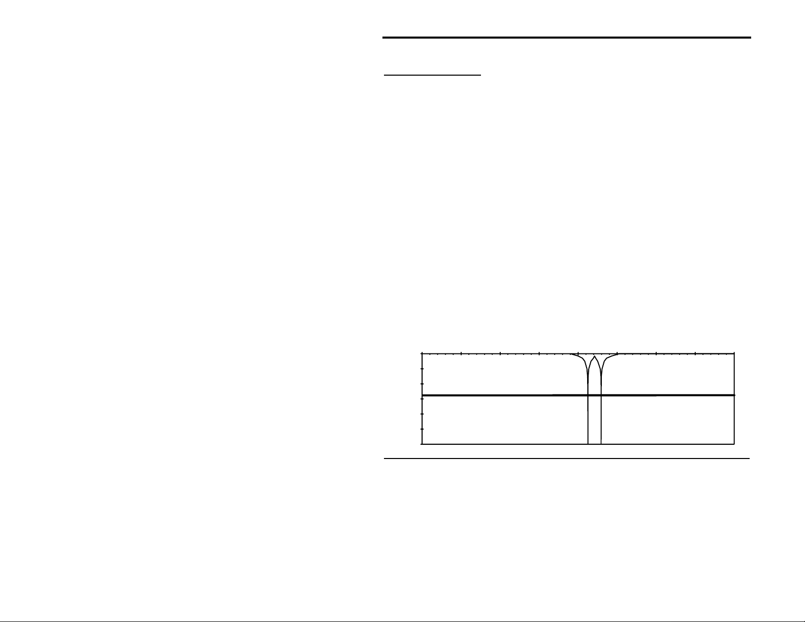
VEC-884 Owner's Manual
Manual Notch Filter
Use: Removes unwanted tones or heterodynes.
Removes up to 2 very narrow frequency ranges and passes all others.
The manual notch filter allo ws the use of two frequency-independent manu ally
tunable notch filters. The Tunable Filters left and right knobs control the
individual notch frequencies (f1 & f2).
The manual notch has tw o different frequency r anges and widths: o ne for the
CW filter and one fo r the other filters. When using the CW filter the notc h is
narrower, 45 Hz @ -40 d B, and has a freque ncy range of 300 Hz to 1000 Hz
(same as the CW filter). In all other modes the notch is wider, 85 Hz @ -40 dB,
and has a frequency range of 150 Hz to 3400 Hz.
For Example: There is RTTY in your SSB audio. After engaging the Manual
Notch button, use the Tunable Filters
left and right knobs
to
notch the two RTTY tones at 2125 and 2295 Hz.
Typical Manual Notch Filter Response
Frequency (Hz)
0 500 1000 1500 2000 2500 3000 3500 4000
0
-20
-40
-60
dB
-80
-100
-120
Filter Description 5-9
Page 62

VEC-884 Owner's Manual
Automatic Notch Filter
Use: Removes multiple tones or heterodynes quickly.
Removes up to 4 changing tones in the presence of speech signals.
The multiple automatic notch filter searches for and eliminates up to four
changing or shifting tones in milli-seconds, with attenuation as great as 50 dB.
All the notches are extremely narrow, res ulting in a minimal effect on the voice
signals. The automatic
notch filter is disabled in the following filter modes:
CW, RTTY, HF PACKET, AMTOR, PACTOR, and SSTV/FAX/WeFAX (including
those stored in memory).
There is an adjustment to change the "speed" of the automatic notch filter.
We call this adjustment the automatic notch aggressiveness. By changing a
jumper setting, this aggressiveness can be changed in a range of four levels.
See the jumper setting section on page 4-8.
Noise Reduction Filter
Use: Removes random noises such as white noise, background hiss, etc.
Removes random noises and passes coherent signals like voices.
The random noise reductio n filter effec tively r emoves no ises in the presenc e of
voice with minimal degradation of the voice itself. The noise reduction filter
works by auto matically for ming consta ntly-varying band-p ass filters around the
coherent components, such as speech, of the audio signal. In effect, this
provides noise reduction by reducing the individual filters' bandwidths to the
minimum required to pass the speech signals intelligently. This filter greatly
reduces operator fatigue during long-term monitoring and makes listening
much more pleasant.
There is a noise reduction control to adjust the reduction characteristics of
the noise reduction filter to prevent s ignal distortion. When this control is in
the full clockwise position, random noises can be attenuated up to 20 dB
(depending on the types of noises).
Filter Description 5-10
Page 63

VEC-884 Owner's Manual
Limited Filters
Filter response is limited to the frequency range of 0-3900 Hz or 175 Hz
minimum in SSB mode. When a filter's center frequency setting is low or high
enough that the bandwidth w ould exceed these frequency ranges, the filter is
"limited." The filter actually changes its center frequency and bandwidth
settings so that it does not exceed these frequency ranges.
Limited filters are pro bably not even noticed by the cas ual operator. However
when using the Talk featur e, an operator may notice a difference in the front
panel controls and the Tunable Filters left and right knob settings. Limited
filters can only occu r in the following filter modes: LR/HR, BP, 2BP, CW, and
SSB.
For example: The Filters switch is set to BP. The Tunable Filters left knob is
set at a 300 Hz center frequency and the Tunable Filters right
knob is set to a bandwidth of 2000 Hz. Obviously the lower
cutoff frequency cannot be -700 Hz. Since the DSP's
frequency range stops at zero, the filter must stop at zero.
The filter's upper cutoff frequency is 1000 Hz above the center
frequency, 1300 Hz. In this case, the DSP limits the BP filter
to 0-1300 Hz (a low-pass filter). Therefore when the Talk
feature is used, the DSP will send the following:
BP CF 650 BW 1300
Filter Description 5-11
Page 64

VEC-884 Owner's Manual
Overlapped Filters
When the passbands of two filters touc h each other, the filters are said to be
"overlapped." The result is a single band-pass filter capable of passing all the
frequencies of the two individual filters. The filter actually changes its center
frequency and bandwidth settings so that the two individual filters are
effectively implemented as a single filter.
The new center frequency, fc, is at the center of the lowest cutoff frequency
and the highest cutoff frequency of the two individual filters:
The new bandwidth, BW, is equal to the sum of the two individual filters'
bandwidths, BW1 and BW2, minus the overlapped region:
Overlapped filters are not notic eable by the oper ato r. Ho wever when us ing the
Talk feature, an operator may notice a difference in the front panel controls
and the Tunable Filters left and right knob settings. Overlapped filters can only
occur in the following filter modes: 2BP and CW with sidetone filter enabled.
fc = (lowest cutoff freq. + highest cutoff freq.) ÷ 2
BW = BW1 + BW2 - (overlapped region)
For example: The Filters switch is set to 2BP. The Tunable Filters left and
right knobs are set at center frequencies of 2000 Hz and
2400 Hz, respectively. The bandw idth of each filter is 600 Hz.
In this case, the upper cutoff frequency of the first filter is
2300 Hz and the lower cutoff frequency of the second filter is
2100. Obviously the two filters overlap each o ther by 200 Hz;
therefore, the DSP implements these two filters as a single
band-pass filter. When the Talk feature is used, the DSP will
send the following:
2BP CF 2200 BW 1000
Filter Description 5-12
Page 65

VEC-884 Owner's Manual
Appendix
Contents of This Appendix
Self-Test Page A-2
>
In Case of Difficulty Page A-4
>
Technical Assistance Page A-4
>
MFJ Pre-wired Cables and Open End Cables Page A-5
>
Pre-Set and Memory Filters Settings Chart Page A-6
>
A
Appendix A-1
Page 66

VEC-884 Owner's Manual
Self-Test
This self-test is used to test all the digital circuitry, switches, and controls of
the VEC-884.
To perform the self-test:
1. Turn the Filters switch to BP.
2. Push all buttons so they are in the "out" position.
3. Turn all knobs to full clockwise, except Volume. Set Volume to a
4. Disengage the Power button and
5. Remove the DSP's cover (6 screws).
6. Remove all jumpers from JMP1 to JMP7. Record their positions to re-
7. Reconnect power.
8. Press and hold the Program button.
9. Press and lock the Power button to "on."
10. Release the Program button. The unit sends
11. Test each button (except the Speaker and Power buttons) by pressing:
12. Test the Filters switch by turning it to each position: LR/HR, BP, 2BP,
13. Test the left Tunable Filters knob by turning it to full counter-clockwise
14. Test the right Tunable Filters and Noise Reduction knobs in the same
15. Test the jumper connections by placing plug-in jumpers on the "L"
Important:
comfortable listening level.
remove the power plug
configure the unit after the self-test.
SELF TEST
.
10 WPM
each operation. If the LEDs blink red the unit fails the test and a Morse
code message is sent to indicate the nature of the failure.
AGC, Program, Memory, Manual Notch, Auto Notch, Nois e Reduction,
and DSP buttons. Skip the Speaker and Power buttons. The LEDs
should blink green once after each button push.
CW, SSB, RTTY, HF PACKET, AMTOR, PACTOR, and SSTV/FAX/
WeFAX. The LEDs should blink green once after each turn of the switch.
then to full clockwise. The LEDs should blink green once at each end.
way. The LEDs should blink green once at each end.
positions of JMP1 to JMP7 (JMP8 is not used). The LEDs should blink
green once for each jumper.
For the entire test, the LEDs should blink green once after
Performing the next step will reset the CW sidetone and the
.
in Morse code at
Pre-Set data filters to factory defaults as described on page 4-
11. If you do not want these filters to reset to factory defaults,
stop this self-test now by releasing the Power button.
Appendix A-2
Page 67

VEC-884 Owner's Manual
16. Test the XMIT/RECEIVE line by short ing pin 5 of the To Radio connector
to ground for approximately one second or until the LEDs blink. If it is
shorted for less than one second, the DSP might signal a false failure.
The LEDs should blink green once when the XMIT/RECEIVE line is
grounded for one second.
17. The filter EEPROM memory, IC U8, is then tested without assistance.
Note that this step will reset the CW sidetone and the Pre-Set data filters
to factory defaults.
18. If you've pressed the buttons, turned the switch and the knobs, placed the
jumpers, and grounded the XMIT/RECEIVE sense line in the correct
order and the unit is working properly, the unit repeatedly sends
(with blinking green LEDs) in Morse code. A repetitive message such as
B4 FAIL
correct order or the unit failed the test. The prefix and the number
indicate the nature of the failure (see table below).
19. Disengage the Power button and
20. Replace all jumpers from JMP1 to JMP7 to their original positions.
21. Replace the DSP's cover (6 screws).
22. Reconnect power and resume with normal operation.
B1
= AGC button
B2
= PROGRAM button
B3
= MEMORY button
B4
= MANUAL NOTCH button
B5
= AUTO NOTCH button
B6
= NOISE REDUCTION button
B7
= SPEAKER button *
B8
= DSP button
B9
= POWER button *
J1
= JMP1 jumper
J2
= JMP2 jumper
J3
= JMP3 jumper
J4
= JMP4 jumper
J5
= JMP5 jumper
J6
= JMP6 jumper
J7
= JMP7 jumper
(with blinking red LEDs) indicates that you didn't follow the
remove the power plug
Prefix-Number and Its Designation
S1
= LR/HR switch position
S2
= BP switch position
S3
= 2BP switch position
S4
= CW switch position
S5
= SSB switch position
S6
= RTTY switch position
S7
= HF PACKET switch position
S8
= AMTOR switch position
S9
= PACTOR switch position
S0
= SSTV/FAX/WeFAX switch position
K1
= TUNABLE FILTERS left knob
K2
= TUNABLE FILTERS right knob
K3
= NOISE REDUCTION knob
K4
= VOLUME knob *
TR
= XMIT/RECEIVE sense
EE
= EEPROM -- IC U8
.
PASS
Appendix A-3
Page 68

VEC-884 Owner's Manual
* These controls are included here for completeness even though they are
not directly tested by this self-test.
Appendix A-4
Page 69

VEC-884 Owner's Manual
In Case of Difficulty
If you experience low volume, hum only when the DSP volume control is
high, or distortion:
Double check the wiring used to connect the DSP to the receiver's speaker
and headphones jacks. The wiring can be tested by turning the DSP "off".
When the DSP power switch is in the "off" position, the audio input jack is
connected directly to the DSP's sp eaker and headphones jacks. If the DSP is
properly connected and the wiring is good, the volume level and audio quality
should be exactly the same as when the speaker or headphones is plugged
directly into the receiver's speaker or headphones jacks.
If the DSP fails to process properly when using the Automatic Notch or
Noise Reduction, or if the DSP audio is distorted intermittently:
The receiver's volume or the DSP's level control may need to be adjusted.
Check the Input Level LED.
If you hear hum at high or low volume:
The power supply you are using may not be filtered properly.
If the DSP won't start or shuts off intermittently:
The power supply may not be within the required 10-16 volt range. If the
power supply drops below 10 volts from poor regulation or a bad connection,
the DSP may operate erratically An indication of poor power is the power LED
flashing from red and green.
Technical Assistance
If you have any problem with this unit first check the appropriate section of this
manual. If the manual does not reference your problem or your problem is not
solved by reading the manual you may call Vectronics toll-free at 601-323-
5800. You will be best helped if you have your unit, manual and all information
on your station handy so you can answer any questions the technicians may
ask.
You can also send questions by mail to Vectronics, 1007 HWY 25 South,
Starkville, MS 39759 or by FAX to 601-323-6551. Send a complete
description of your problem, an explanation of exactly how you are using your
unit and a complete description of your station.
Appendix A-5
Page 70

VEC-884 Owner's Manual
MFJ Pre-wired Cables and Open End Cables
The following MFJ radio-to-TNC cables are pre-wired for most 8-pin rigs and
HTs. The open end cables allow you to make your own cables. For your
nearest dealer or to order call toll-free 800-647-1800.
Pre-wired Radio-to-DSP Cables
Radio
MFJ Part #
Icom1/Yaesu/Alinco/Radio Shack HTs MFJ-5024 $14.95
Kenwood2 HTs MFJ-5026 $14.95
Yaesu 8-pin MFJ-5080 $14.95
Yaesu 8-pin modular MFJ-5080M $14.95
Icom3 8-pin MFJ-5084 $14.95
Icom4 8-pin modular MFJ-5084M $14.95
Kenwood/Alinco 8-pin MFJ-5086 $14.95
Kenwood 8-pin modular MFJ-5086M $14.95
Radio Shack 8-pin modular MFJ-5088M $14.95
MFJ-8621 Data Radio MFJ-5100 $14.95
Note 1: Doe s not include IC-W2A. Note 3: Does not include 25A, 255A.
Note 2: Does not include 2500. Note 4: Does not include IC-100H, I C-2700H.
Price
*
Pre-wired DSP-to-TNC Cables
TNC
All MFJ TNCs/PK-900/PK-96/PK-12/PacCom/
MFJ Part #
MFJ-5100 $14.95
other TNC-2 compatibles
PK-232 MFJ-5100X $14.95
KAM HF5/KAM VHF5/KPC35/KPC96125 MFJ-5100YH6 $14.95
MFJ-5100YV7 $14.95
PK-88 MFJ-5100Z $14.95
Note 5: YH for KAM HF port. YV for KAM VHF port. Other Kantronics use YV models.
Note 6: YH models for KPC9612 9600 baud port.
Note 7: YV for KPC9612 1200 baud port.
Price
*
Open End Cables With Radio Connectors
Open End Cable ...
... with 8-pin mic connector MFJ-5082 $9.95
... with 5-pin DIN connector (general purpose) MFJ-5205 $4.95
... with split connectors for Alinco & other hand-helds MFJ-5222 $9.95
... for Icom/Yaesu/Alinco/Radio Shack hand-helds MFJ-5224 $9.95
... for Kenwood hand-helds MFJ-5226 $9.95
... with 8-pin modular mic plug for Yaesu, Ke nwood,
Icom, and Radio Shack
*
Prices as of June 30, 1995. Prices subject to change without notice.
MFJ Part #
Price
MFJ-5268 $9.95
Appendix A-6
*
Page 71

VEC-884 Owner's Manual
Pre-Set and Memory Filters Settings Chart
Copy this chart and use it to record your Pre-Set and memory filters settings.
Use the Talk function to get the frequency values for CF, BW, and/or LR-HR.
Pre-Set RTTY Mode
Mark-Space _____________________
Baud Rate _____________________
Pre-Set AMTOR Mode
Mark-Space _____________________
Baud Rate _____________________
Pre-Set HF PACKET Mode
Mark-Space _____________________
Baud Rate _____________________
Pre-Set PACTOR Mode
Mark-Space _____________________
Baud Rate _____________________
Memory 1
Operation Conditions/Radio Frequency
________________________________
________________________________
CF, BW ________________________
LR-HR ________________________
Memory 3
Operation Conditions/Radio Frequency
________________________________
________________________________
CF, BW ________________________
LR-HR ________________________
Memory 5
Operation Conditions/Radio Frequency
________________________________
________________________________
CF, BW ________________________
LR-HR ________________________
Memory 7
Operation Conditions/Radio Frequency
________________________________
________________________________
CF, BW ________________________
LR-HR ________________________
Memory 9
Operation Conditions/Radio Frequency
________________________________
________________________________
CF, BW ________________________
LR-HR ________________________
Mode: ___________
Mode: ____________
Mode: ___________
Mode: ___________
Mode: ___________
Memory 2
Operation Conditions/Radio Frequency
________________________________
________________________________
CF, BW ________________________
LR-HR ________________________
Memory 4
Operation Conditions/Radio Frequency
________________________________
________________________________
CF, BW ________________________
LR-HR ________________________
Memory 6
Operation Conditions/Radio Frequency
________________________________
________________________________
CF, BW ________________________
LR-HR ________________________
Memory 8
Operation Conditions/Radio Frequency
________________________________
________________________________
CF, BW ________________________
LR-HR ________________________
Memory 10
Operation Conditions/Radio Frequency
________________________________
________________________________
CF, BW ________________________
LR-HR ________________________
Mode: ___________
Mode: ___________
Mode: ___________
Mode: ___________
Mode: ___________
Appendix A-7
Page 72

VEC-884 Owner's Manual
Pre-Set and Memory Filters Settings Chart
Copy this chart and use it to record your Pre-Set and memory filters settings.
Use the Talk function to get the frequency values for CF, BW, and/or LR-HR.
Pre-Set RTTY Mode
Mark-Space _____________________
Baud Rate _____________________
Pre-Set AMTOR Mode
Mark-Space _____________________
Baud Rate _____________________
Pre-Set HF PACKET Mode
Mark-Space _____________________
Baud Rate _____________________
Pre-Set PACTOR Mode
Mark-Space _____________________
Baud Rate _____________________
Memory 1
Operation Conditions/Radio Frequency
________________________________
________________________________
CF, BW ________________________
LR-HR ________________________
Memory 3
Operation Conditions/Radio Frequency
________________________________
________________________________
CF, BW ________________________
LR-HR ________________________
Memory 5
Operation Conditions/Radio Frequency
________________________________
________________________________
CF, BW ________________________
LR-HR ________________________
Memory 7
Operation Conditions/Radio Frequency
________________________________
________________________________
CF, BW ________________________
LR-HR ________________________
Memory 9
Operation Conditions/Radio Frequency
________________________________
________________________________
CF, BW ________________________
LR-HR ________________________
Mode: ___________
Mode: ____________
Mode: ___________
Mode: ___________
Mode: ___________
Memory 2
Operation Conditions/Radio Frequency
________________________________
________________________________
CF, BW ________________________
LR-HR ________________________
Memory 4
Operation Conditions/Radio Frequency
________________________________
________________________________
CF, BW ________________________
LR-HR ________________________
Memory 6
Operation Conditions/Radio Frequency
________________________________
________________________________
CF, BW ________________________
LR-HR ________________________
Memory 8
Operation Conditions/Radio Frequency
________________________________
________________________________
CF, BW ________________________
LR-HR ________________________
Memory 10
Operation Conditions/Radio Frequency
________________________________
________________________________
CF, BW ________________________
LR-HR ________________________
Mode: ___________
Mode: ___________
Mode: ___________
Mode: ___________
Mode: ___________
Appendix A-8
Page 73
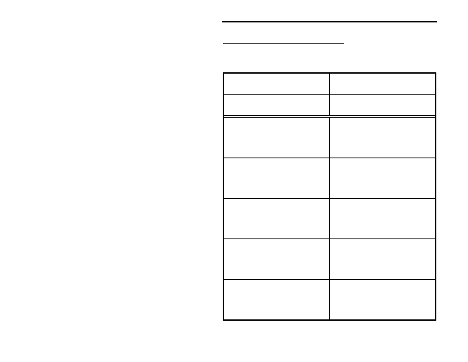
VEC-884 Owner's Manual
Pre-Set and Memory Filters Settings Chart
Copy this chart and use it to record your Pre-Set and memory filters settings.
Use the Talk function to get the frequency values for CF, BW, and/or LR-HR.
Pre-Set RTTY Mode
Mark-Space _____________________
Baud Rate _____________________
Pre-Set AMTOR Mode
Mark-Space _____________________
Baud Rate _____________________
Pre-Set HF PACKET Mode
Mark-Space _____________________
Baud Rate _____________________
Pre-Set PACTOR Mode
Mark-Space _____________________
Baud Rate _____________________
Memory 1
Operation Conditions/Radio Frequency
________________________________
________________________________
CF, BW ________________________
LR-HR ________________________
Memory 3
Operation Conditions/Radio Frequency
________________________________
________________________________
CF, BW ________________________
LR-HR ________________________
Memory 5
Operation Conditions/Radio Frequency
________________________________
________________________________
CF, BW ________________________
LR-HR ________________________
Memory 7
Operation Conditions/Radio Frequency
________________________________
________________________________
CF, BW ________________________
LR-HR ________________________
Memory 9
Operation Conditions/Radio Frequency
________________________________
________________________________
CF, BW ________________________
LR-HR ________________________
Mode: ___________
Mode: ____________
Mode: ___________
Mode: ___________
Mode: ___________
Memory 2
Operation Conditions/Radio Frequency
________________________________
________________________________
CF, BW ________________________
LR-HR ________________________
Memory 4
Operation Conditions/Radio Frequency
________________________________
________________________________
CF, BW ________________________
LR-HR ________________________
Memory 6
Operation Conditions/Radio Frequency
________________________________
________________________________
CF, BW ________________________
LR-HR ________________________
Memory 8
Operation Conditions/Radio Frequency
________________________________
________________________________
CF, BW ________________________
LR-HR ________________________
Memory 10
Operation Conditions/Radio Frequency
________________________________
________________________________
CF, BW ________________________
LR-HR ________________________
Mode: ___________
Mode: ___________
Mode: ___________
Mode: ___________
Mode: ___________
Appendix A-9
Page 74

VEC-884 Owner's Manual
Pre-Set and Memory Filters Settings Chart
Copy this chart and use it to record your Pre-Set and memory filters settings.
Use the Talk function to get the frequency values for CF, BW, and/or LR-HR.
Pre-Set RTTY Mode
Mark-Space _____________________
Baud Rate _____________________
Pre-Set AMTOR Mode
Mark-Space _____________________
Baud Rate _____________________
Pre-Set HF PACKET Mode
Mark-Space _____________________
Baud Rate _____________________
Pre-Set PACTOR Mode
Mark-Space _____________________
Baud Rate _____________________
Memory 1
Operation Conditions/Radio Frequency
________________________________
________________________________
CF, BW ________________________
LR-HR ________________________
Memory 3
Operation Conditions/Radio Frequency
________________________________
________________________________
CF, BW ________________________
LR-HR ________________________
Memory 5
Operation Conditions/Radio Frequency
________________________________
________________________________
CF, BW ________________________
LR-HR ________________________
Memory 7
Operation Conditions/Radio Frequency
________________________________
________________________________
CF, BW ________________________
LR-HR ________________________
Memory 9
Operation Conditions/Radio Frequency
________________________________
________________________________
CF, BW ________________________
LR-HR ________________________
Mode: ___________
Mode: ____________
Mode: ___________
Mode: ___________
Mode: ___________
Memory 2
Operation Conditions/Radio Frequency
________________________________
________________________________
CF, BW ________________________
LR-HR ________________________
Memory 4
Operation Conditions/Radio Frequency
________________________________
________________________________
CF, BW ________________________
LR-HR ________________________
Memory 6
Operation Conditions/Radio Frequency
________________________________
________________________________
CF, BW ________________________
LR-HR ________________________
Memory 8
Operation Conditions/Radio Frequency
________________________________
________________________________
CF, BW ________________________
LR-HR ________________________
Memory 10
Operation Conditions/Radio Frequency
________________________________
________________________________
CF, BW ________________________
LR-HR ________________________
Mode: ___________
Mode: ___________
Mode: ___________
Mode: ___________
Mode: ___________
Appendix A-10
Page 75

VEC-884 Owner's Manual
Notes
Appendix A-11
Page 76

VEC-884 Owner's Manual
Notes
Appendix A-12
 Loading...