

Page 1

IMPORTANT WARRANTY INFORMATION! PLEASE READ
Return Policy on Kits When Not Purchased Directly From Vectronics: Before continuing
any further with your VEC kit check with your Dealer about their return policy. If your Dealer
allows returns, your kit must be returned before you begin construction.
Return Policy on Kits When Purchased Directly From Vectronics: Your VEC kit may be
returned to the factory in its pre-assembled condition only. The reason for this stipulation is,
once you begin i nsta lli ng a nd sol deri ng pa rt s, you essenti al ly tak e over the rol e of the devic e's
manufacturer . From this point on, neither Vect ronics nor its dea lers can reas onably be held
accountab le for the qua lity or the outcome of your work. Because of this, Vectronics cannot
accept return of any kit-in-progress or completed work as a warranty item for any reason
whatsoever. If you are a new or inexperienced kit b uilder, we urge you to read the manual
carefully a nd determine whether or not you're r eady to tak e on the job. If you wish to c hange
your mind and return your ki t, you may--b ut you must do i t before you begin c ons tr uc ti on, a nd
within ten (10) working days of the time it arrives.
Vectronics Warrants: Your kit contains each item specified in the parts list.
Missing Parts: If you determine, during your pre-construction inventory, that any part is
missing, please contact Vectronics and we'll send the missing item to you free of charge.
However, before you contact Vect ronic s, please look carefully to c onf ir m you haven't misr ea d
the marking on one of the other items provided with the kit. Also, make certain an alternative
part hasn't been substituted for the item you're missing. If a specific part is no longer
available, or if Engineering has determined that an alternative component is more suitable,
Vectronics reserves the right to make substitutions at any time. In most cases, these changes
will be clearly noted in an addendum to the manual.
Defective Parts: Today's electronic parts are physically and electrically resilient, and
defective components a re r a re. However, if you disc over a n it em duri ng your pr e- c onst r uct i on
inventory that's obviously broken or unserviceable, we'll replace it. Just return the part to
Vectronics at the address below accompanied with an explanation. Upon receipt, we'll test it.
If it's defec tive and appear s unused, we'll ship you a new one right away at no charge.
Missing or Defective Parts After You Begin Assembly: Parts and materials lost or
damaged after construction begins are not covered under the terms of this warranty. However,
most parts supplied with VEC kits are relatively inexpensive and Vectronics can replace them
for a reasonable charge. Simply contact the factory with a complete description. We'll
process your order quickly and get you back on trac k.
Factory Repair After You Begin Assembly: Kits-in progress and completed kits are
specifically excluded from coverage by the Vectronics warranty. However, as a service to
customers, tec hnicia ns ar e availa ble t o evaluate a nd repai r malf unctioni ng kits for a minimum
service fee of $18.00 (½ hour rate) plus $7.00 shipping and handling (prices subject to
change). To qualify for repair service, your kit must be fully completed, unmodified, and the
printed circuit board assembled using rosin-core solder. In the event your repair will require
more than an hour to fi x (or $36.00, subject to change), our technicians will contact you in
advance by telephone b efore p erforming t he work. Def ective unit s should b e shipp ed prep aid
to:
Vectronics
1007 HWY 25 South
Starkville, MS 39759
Page 2

When shipping, pack your kit well and include the minimum payment plus shipping and
handling charges ($25.00 total). No work can be performed without pre-payment. Also,
provide a valid UPS return address a nd a day time phone number where you may be reac hed.
Page 3

VEC-841K Owner's Manual Tunable SSB/CW Audio Filter Kit
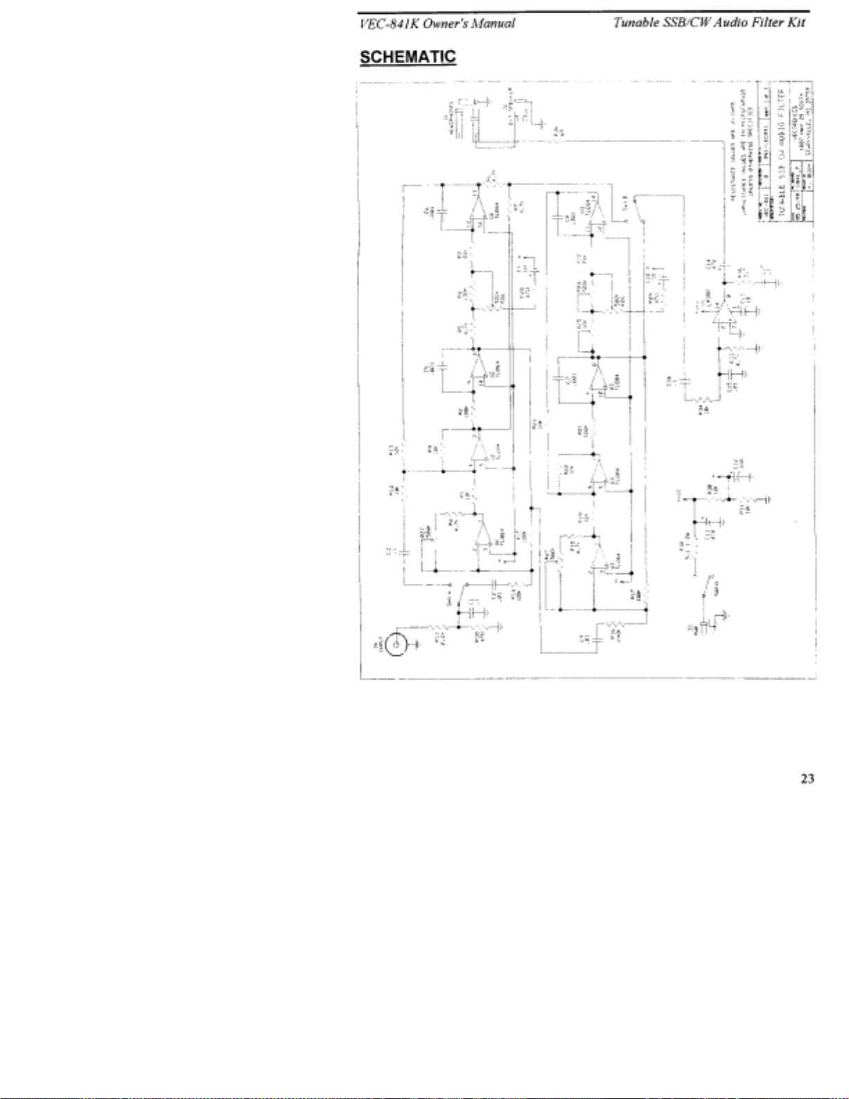
INTRODUCTION
Thank you for purchasing the VEC-841K Tunable CW Audio Filter kit. The
VEC-841K consists of a four stage, switch selectable band pass CW filter, using
selected components that will make “cleaning up” CW signals effortless and
easy. Featuring razor sharp selectivity and extremely steep sided skirts, and a
Tunable Notch, makes even the weakest signal stand out. Also, the VEC-841K
has a built-in 1 watt audio amplifier that will easily drive headphones or an
external speaker. With the VEC-841K you bring up any hard to hear signal out
of a “band pi le up” for ea sy listening, or get ri d of unwanted, annoying signals.
The VEC-841K also features a headphone output that will allow the use of
standard mono headphones. The VEC-841K is powered from any 9-18 volt DC
power supply.
TOOLS AND SUPPLIES
Construction Area:
area where you can easily organize and handle small parts without losing them.
An inexpensive sheet of white poster board makes an excellent construction
surface, while providing protection for the underlying table or desk. Welldiffused overhead lighting is a plus, and a supplemental high-intensity desk lamp
will prove especially helpful for close-up work. Safety is an important
consideration. Be sure to use a suitable high-temperature stand for your
soldering iron, and keep the work area free of combustible clutter.
Universal Kit-building Tools:
additional items to complete, virtually all construction projects require a work
area outfitted with the following tools and supplies:
!
30-60 watt Soldering Iron
!
High-temperature Iron Holder with a Moist Cleaning Sponge
!
Rosin-core Solder (thin wire-size preferred)
!
Needle Nose Pliers or Surgical Hemostats
!
Diagonal Cutters or "Nippy Cutters"
!
Wire Strippers
!
Solder Sucker, Vacuum Pump, or Desoldering Braid
!
Bright Desk Lamp
!
Magnifying Glass
Kit construction requires a clean, smooth, and well-lighted
Although your particular kit may require
1
Page 4

VEC-841K Owner's Manual Tunable SSB/CW Audio Filter Kit
BEFORE YOU START BUILDING
Experience shows there are four common mistakes builders make. Avoid these,
and your kit will probably work on the first try! Here's what they are:
1. Installing the Wrong Part:
and a 10K resistor may look almost the same, but they may act very
differently in an electronic circuit! Same for capacitors--a device marked
102 (or .001 uF) may have very different operating characteristics from one
marked 103 (or .01uF).
2. Installing Parts Backwards:
capacitors to make sure the positive (+) lead goes in the (+) hole on the
circuit board. Transistors have a flat side or emitter tab to help you identify
the correct mounting position. ICs have a notch or dot at one end indicating
the correct direction of insertion. Diodes have a banded end indicating
correct polarity. Always double-check--especially before applying power to
the circuit!
3. Faulty Solder Connections:
bridges. Cold solder joints happen when you don't fully heat the connection-or when metallic corrosion and oxide contaminate a component lead or pad.
Solder bridges form when a trail of excess solder shorts pads or tracks
together (see Solder Tips below).
4. Omitting or Misreading a Part:
Always double-check to make sure you completed each step in an assembly
sequence.
Soldering Tips:
professional soldering. Before you install and solder each part, inspect leads or
pins for oxidation. If the metal surface is dull, sand with fine emery paper until
shiny. Also, clean the oxidation and excess solder from the soldering iron tip to
allow maximum heat transfer. Allow the tip of your iron to contact both the lead
and pad for about one second (count "one-thousand-one") before feeding solder
to the connection. Surfaces must become hot enough for solder to flow
smoothly. Feed solder to the opposite side of the lead from your iron tip--solder
will wick around the lead toward the tip, wetting all exposed surfaces. Apply
solder sparingly, and do not touch solder directly to the hot iron tip to promote
rapid melting.
Cleanliness and good heat distribution are the two secrets of
It always pays to double-check each step. A 1K
Always check the polarity of electrolytic
Inspect for cold-solder joints and solder
This is easier to do than you might think!
Desoldering Tips:
these instructions carefully! First, grasp the component with a pair of hemostats
or needle-nose pliers. Heat the pad beneath the lead you intend to extract, and
pull gently. The lead should come out. Repeat for the other lead. Solder may
fill in behind the lead as you extract it--especially if you are working on a
2
If you make a mistake and need to remove a part, follow
Page 5
VEC-841K Owner's Manual Tunable SSB/CW Audio Filter Kit
double-sided b o ar d with plat e-thr o ugh hol es. Sho uld this ha pp e n, tr y heat ing the
pad again and inserting a common pin into the hole. Solder won't stick to the
pin's chromium plating. When the pad cools, remove the pin and insert the
correct component. For ICs or multi-pin parts, use desoldering braid to remove
excess solder before attempting to extract the part. Alternatively, a low-cost
vacuum-bulb or spring-loaded solder sucker may be used. Parts damaged or
severely overheated during extraction should be replaced rather than reinstalled.
Work Habits:
instructions and, in many cases, to perform new and unfamiliar tasks. To avoid
making needless mistakes, work for short periods when you're fresh and alert.
Recreational construction project are more informative and more fun when you
take your time. Enjoy!
Sorting and Reading Resistors:
a color code (shown below). You don't have to memorize this code to work with
resistors, but you do need to understand how it works:
Kit construction requires the ability to follow detailed
The electrical value of resistors is indicated by
Resistor Color Code
Black = 0 (tens)
1st Digit
2nd Digit
Multiplier
Tolerence
(gold or silver)
When you look at a resistor, check its multiplier code first. Any resistor with a
black multiplier band falls between 10 and 99 ohms in value. Brown designates
a value between 100 and 999 ohms. Red indicates a value from 1000 to 9999
ohms, which is also expressed as 1.0K to 9.9K. An orange multiplier band
designates 10K to 99K, etc. To sort and inventory resistors, first separate them
into groups by multiplier band (make a pile of 10s, 100s, Ks, 10Ks, etc.). Next,
sort each group by specific value (1K, 2.2K, 4.7K, etc.). This procedure makes
the inventory easier, and also makes locating specific parts more convenient later
on during construction. Some builders find it especially helpful to arrange
resistors in ascending order along a strip of double-sided tape.
Brown = 1 (hundreds)
Red = 2 (K)
Orange = 3 (10K)
Yellow = 4 (100K)
Green = 5 (1Meg)
Blue = 6
Violet = 7
Gray = 8
White = 9
Silver = 10%
Gold = 5%
Some VEC kits may contain molded chokes which appear, at first glance, similar
to resistors in both shape and band marking. However, a closer look will enable
you to differentiate between the two--chokes are generally larger in diameter and
fatter at the ends than resistors. When doing your inventory, separate out any
chokes and consult the parts list for specific color-code information.
3
Page 6
VEC-841K Owner's Manual Tunable SSB/CW Audio Filter Kit
l
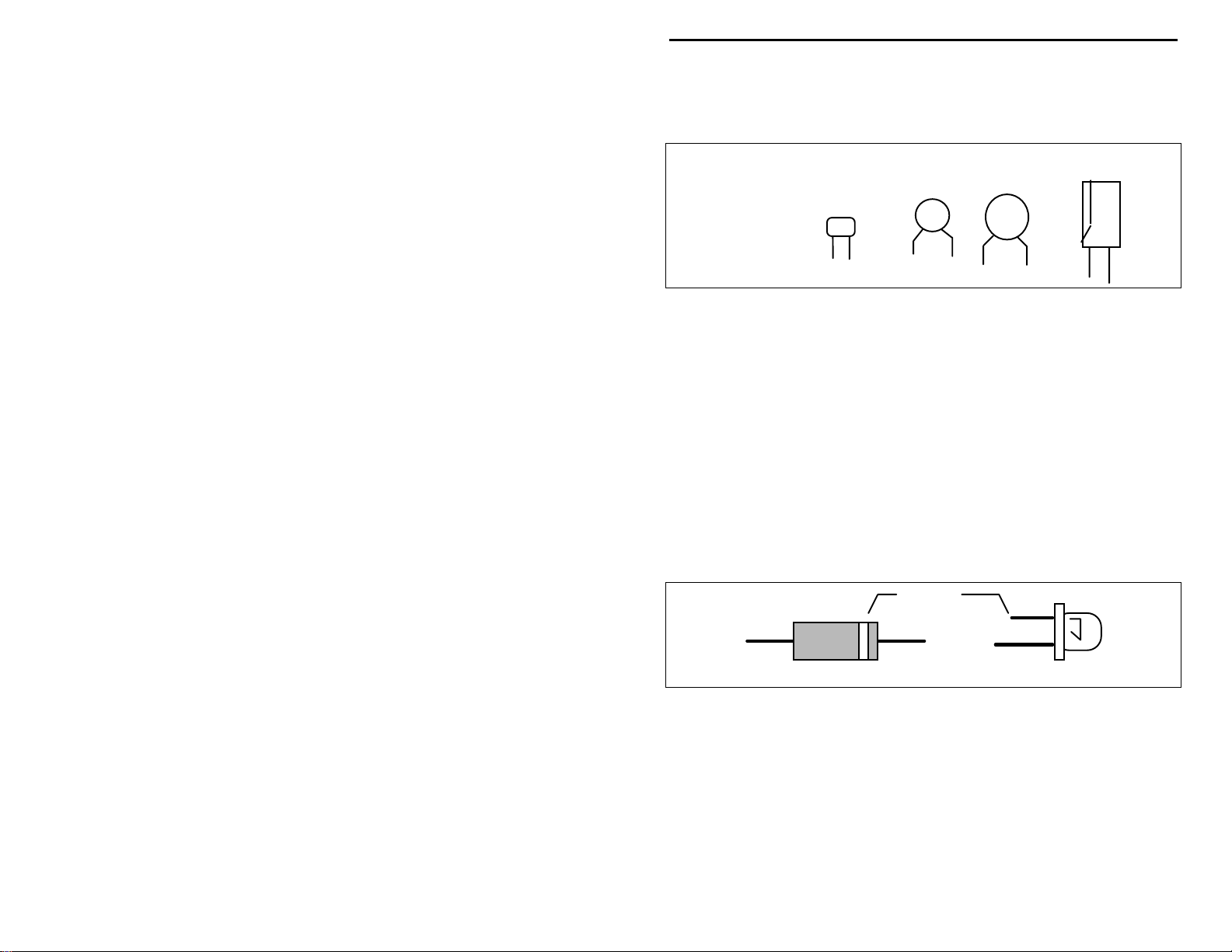
Reading Capacitors:
value identification. Instead, the value, or a 3-number code, is printed on the
body.
Value Code
10 pF = 100
100 pF = 101
1000 pF = 102
.001 uF = 102*
.01 uF = 103
.1 uF = 104
As with resistors, it's helpful to sort capacitors by type, and then to arrange them
in ascending order of value. Small-value capacitors are characterized in pF (or
pico-Farads), while larger values are labeled in uF (or micro-Farads). The
transition from pF to uF occurs at 1000 pF (or .001 uF)*. Today, most
monolithic and disc-ceramic capacitors are marked with a three-number code.
The first two digits indicate a numerical value, while the last digit indicates a
multiplier (same as resistors).
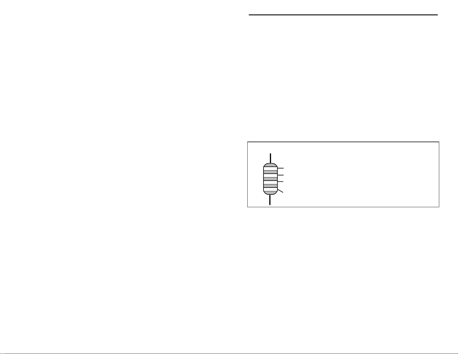
Electrolytic capacitors are always marked in uF. Electrolytics are polarized
devices and must be oriented correctly during installation. If you become
confused by markings on the case, remember the uncut negative lead is slightly
shorter than the positive lead.
Diodes:
Always look for the banded or cathode end when installing, and follow
instructions carefully.
Diodes are also polarized devices that must be installed correctly.
Unlike resistors, capacitors no longer use a color code for
E
ectrolytic
1 uF
1uF
|
35V
|
-
+
Multilayer
(270 pF)
271
Ceramic Discs
(.001 uF) (.1 uF)
102
104
Cathode
(shorter Lead)
Diode
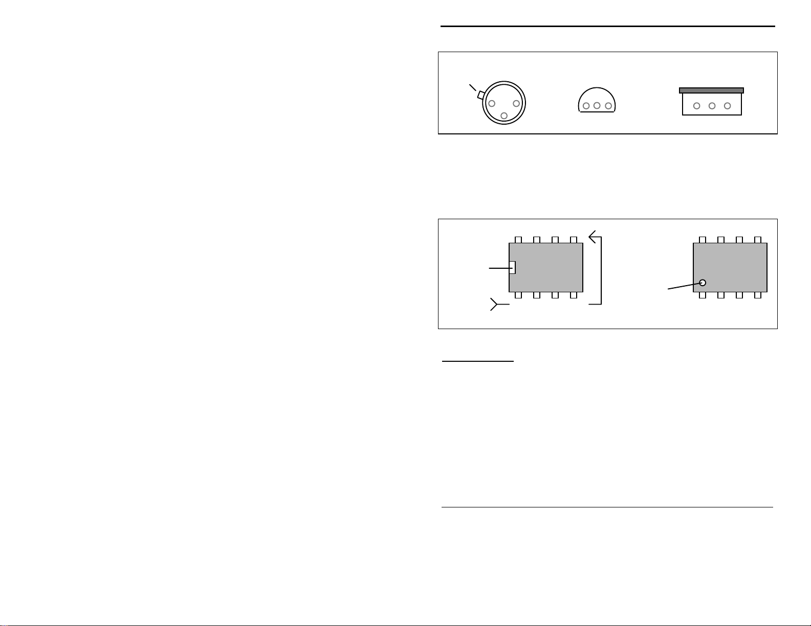
Transistors:
power is applied. Transistors in metal cases have a small tab near the emitter
lead to identify correct positioning. Semiconductors housed in small plastic
cases (TO-92) have an easily-identified flat side to identify mounting orientation.
Many specialized diodes and low-current voltage regulators also use this type
packaging. Larger plastic transistors and voltage regulators use a case backed
with a prominent metal tab to dissipate heat (T-220). Here orientation is
indicated by the positioning of the cooling tab.
4
If transistors are installed incorrectly, damage may result when
LED
Page 7
VEC-841K Owner's Manual Tunable SSB/CW Audio Filter Kit
Metal Can Device Plastic Device Tab-cooled Device
Emitter
Flat Side
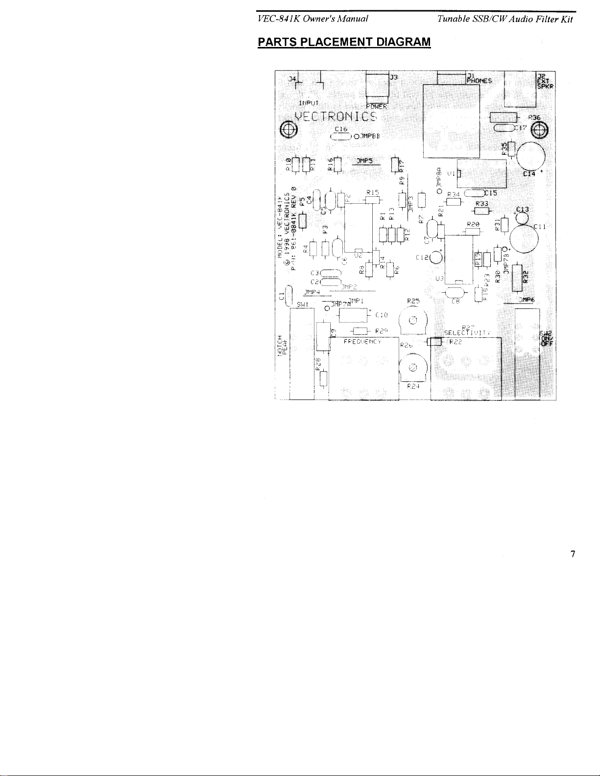
Integrated Circuits:
marking located on one end of the device. A corresponding mark will be silkscreened on the PC board and printed on the kit's parts-placement diagram. To
identify specific IC pin numbers for testing purposes, see the diagram below.
Pin numbers always start at the keyed end of the case and progress counterclockwise around the device, as shown:
Installation
Key
Proper IC positioning is indicated by a dot or square
8 7 6 5
Installation
Key
1 2 3 4
Pin Numbers
Metal Tab
PARTS LIST
Your kit should contain all of the parts in the foll owing list. Please go thro ugh
the parts bag to identify and inventory each item on the checklist before you start
building. If any par ts are missing or damaged, r efer to the warranty section of
this manual for replacement instructions. If you can't positively identify an
unfamiliar item in the bag on the basis of the information given, set it aside until
all other items are checked off. You may then be able to identify it by process of
elimination. Finally, your kit will go together more smoothly if parts are
organized by type and arranged by value ahead of time. Use this inventory as an
opportunity to sort and arrange parts so you can identify and find them quickly.
Qty Part Description Designation
"
Fixed Resistors:
!
1 2.7 ohm resistor (red-violet-gold) R35
!
1 5.1 ohm, 1/2 watt resistor (green-brown-gold) R32
!
1 68 ohm resistor; 1/2 watt (blue-gray-black) R36
!
3 470 ohm resistor (yellow-violet-brown) R10, R28, R29
5
Page 8

VEC-841K Owner's Manual Tunable SSB/CW Audio Filter Kit
!
1 2.2K ohm resistor (red-red-red) R11
!
6 4.7K ohm resistor (yellow-violet-red) R5, R6, R7, R8
R18, R33
!
10 10K ohm resistor (brown-black-orange) R1, R9, R12, R13
R19, R20, R23
R30, R31, R34
!
2 24K ohm resistor (red-yellow-orange) R3, R22
!
5 100K ohm resistor (brown-black-yellow) R2, R14, R15
R17, R21
!
1 130K ohm resistor (brown-orange-yellow) R4
!
1 240K ohm resistor (red-yellow-yellow) R16
Capacitors:
!
4 .1uF disc ceramic capacitor (104, 104Z) C1, C3, C16, C17
!
3 .01uF disc ceramic capacitor (103, 103Z) C2, C4, C15
!
4 1000pF polystyrene capacitors (1000J) C5, C6, C7, C8
!
1 100uF electrolytic capacitor C12
!
2 470uF electrolytic capacitor C11, C14
!
1 10uF electrolytic capacitor (radial leads) C13
!
2 10uF electrolytic capacitor (axial leads) C9, C10
Semi-conductors:
!
2 TL084 quad operational amplifiers IC U2, U3
!
1 LM380 2 watt audio amplifier IC U1
Miscellaneous:
!
1 10K ohm horizontal trimpot (10K or 103) R25
!
1 500K ohm horizontal trimpot (500K or 504) R24
!
2 500K Dual Linear potentiometer R26, R27
!
2 2-pole 2-position push button switch SW1, SW2
!
1 RCA phono jack J4
!
1 1/4" stereo phone jack J1
!
1 3.5mm stereo jack J2
!
1 2.1mm coaxial DC jack J3
!
3 14-pin IC sockets For U1, U2, U3
!
2 6" insulated stranded wires Circuit wiring
!
1 VEC-841K PC board
!
1 Instruction Manual
PARTS PLACEMENT DIAGRAM
6
Page 9
Page 10

VEC-841K Owner's Manual Tunable SSB/CW Audio Filter Kit
STEP-BY-STEP ASSEMBLY
Before assembling your kit, please take time to read and understand the VEC kit
warranty printed on the inside cover of this manual. Also, read through the
assembly instructions to make sure the kit does not exceed your skill level. Once
you begin construction, your kit will be non-returnable. Finally, if you haven't
already done so, please verify that all parts listed in the inventory are included.
If anything is missing or broken, refer to the warranty instructions for replacing
missing or damaged parts.
Note that part designators, such as R1, C3, etc., appear on a silk-screened legend
on the component-mounting side of the printed circuit board. This corresponds
with the parts placement page in the manual. All parts will be inserted on the
silk-screen side of the board.
If you have la st-minute questions about what you need to build your kit, p lease
refer back to the section titled "Tools and Supplies" . If you're ready to begin
now, here we go! The directions use two sets of check boxes. Check one when
a step is complete and use the other for double-checking your work before
operation.
Installing Resistors:
! !
1. Locate resistor R35. This is a 2.7 ohm resistor (red-violet-gold).
Carefully bend the leads close to the resistor body to form right-angles (see
following diagram).
.4"
! !
2. Insert R35 into its mounting holes so the resistor body rests against the
board. Solder in place and trim the leads.
! !
3. Locate resistor R10. This is a 470 ohm resistor (yellow-violet-brown).
Carefully bend the leads close to the resistor body as in Step #1. Insert
at R10, solder in place and trim the leads
! !
4. Locate resistor R28. This is a 470 ohm resistor (yellow-violet-brown).
Carefully bend the leads close to the resistor body as in Step #1. Insert
at R28, solder in place and trim the leads.
! !
5. Locate resistor R29. This is a 470 ohm resistor (yellow-violet-brown).
Carefully bend the leads close to the resistor body as in Step #1. Insert
at R29, solder in place and trim the leads.
7
Page 11

VEC-841K Owner's Manual Tunable SSB/CW Audio Filter Kit
! !
6. Locate resistor R11. This is a 2.2K resistor (red-red-red). Carefully
bend the leads close to the resistor body as in Step #1. Insert at R11,
solder in place and trim the leads.
! !
7. Locate resistor R5. This is a 4.7K resistor (yellow-violet-red).
Carefully bend the leads close to the resistor body as in Step #1. Insert
at R5, solder in place and trim the leads.
! !
8. Locate resistor R6. This is a 4.7K resistor (yellow-violet-red).
Carefully bend the leads close to the resistor body as in Step #1. Insert
at R6, solder in place and trim the leads.
! !
9. Locate resistor R7. This is a 4.7K resistor (yellow-violet-red).
Carefully bend the leads close to the resistor body as in Step #1. Insert
at R7, solder in place and trim the leads.
! !
10. Locate resistor R8. This is a 4.7K resistor (yellow-violet-red).
Carefully bend the leads close to the resistor body as in Step #1. Insert
at R8, solder in place and trim the leads.
! !
11. Locate resistor R18. This is a 4.7K resistor (yellow-violet-red).
Carefully bend the leads close to the resistor body as in Step #1. Insert
at R18, solder in place and trim the leads.
! !
12. Locate resistor R33. This is a 4.7K resistor (yellow-violet-red).
Carefully bend the leads close to the resistor body as in Step #1. Insert
at R33, solder in place and trim the leads.
! !
13. Locate resistor R1. This is a 10K resistor (brown-black-orange).
Carefully bend the leads close to the resistor body as in Step #1. Insert
at R1, solder in place and trim the leads.
! !
14. Locate resistor R9 This is a 10K resistor (brown-black-orange).
Carefully bend the leads close to the resistor body as in Step #1. Insert
at R9, solder in place and trim the leads.
! !
15. Locate resistor R12. This is a 10K resistor (brown-black-orange).
Carefully bend the leads close to the resistor body as in Step #1. Insert
at R12, solder in place and trim the leads.
! !
16. Locate resistor R13. This is a 10K resistor (brown-black-orange).
Carefully bend the leads close to the resistor body as in Step #1. Insert
at R13, solder in place and trim the leads.
! !
17. Locate resistor R19. This is a 10K resistor (brown-black-orange).
Carefully bend the leads close to the resistor body as in Step #1. Insert
at R19, solder in place and trim the leads.
8
Page 12

VEC-841K Owner's Manual Tunable SSB/CW Audio Filter Kit
! !
18. Locate resistor R20. This is a 10K resistor (brown-black-orange).
Carefully bend the leads close to the resistor body as in Step #1. Insert
at R20, solder in place and trim the leads.
! !
19. Locate resistor R23. This is a 10K resistor (brown-black-orange).
Carefully bend the leads close to the resistor body as in Step #1. Insert
at R23, solder in place and trim the leads.
! !
20. Locate resistor R30. This is a 10K resistor (brown-black-orange).
Carefully bend the leads close to the resistor body as in Step #1. Insert
at R30, solder in place and trim the leads.
! !
21. Locate resistor R31. This is a 10K resistor (brown-black-orange).
Carefully bend the leads close to the resistor body as in Step #1. Insert
at R31, solder in place and trim the leads.
! !
22. Locate resistor R34. This is a 10K resistor (brown-black-orange).
Carefully bend the leads close to the resistor body as in Step #1. Insert
at R34, solder in place and trim the leads.
! !
23. Locate resistor R3. This is a 24K resistor (red-yellow-orange).
Carefully bend the leads close to the resistor body as in Step #1. Insert
at R3, solder in place and trim the leads.
! !
24. Locate resistor R22. This is a 24K resistor (red-yellow-orange).
Carefully bend the leads close to the resistor body as in Step #1. Insert
at R22, solder in place and trim the leads.
! !
25. Locate resistor R2. This is a 100K resistor (brown-black-yellow).
Carefully bend the leads close to the resistor body as in Step #1. Insert
at R2, solder in place and trim the leads.
! !
26. Locate resistor R14. This is a 100K resistor (brown-black-yellow).
Carefully bend the leads close to the resistor body as in Step #1. Insert
at R14, solder in place and trim the leads.
! !
27. Locate resistor R15. This is a 100K resistor (brown-black-yellow).
Carefully bend the leads close to the resistor body as in Step #1. Insert
at R15, solder in place and trim the leads.
! !
28. Locate resistor R17. This is a 100K resistor (brown-black-yellow).
Carefully bend the leads close to the resistor body as in Step #1. Insert
at R17, solder in place and trim the leads.
! !
29. Locate resistor R21. This is a 100K resistor (brown-black-yellow).
Carefully bend the leads close to the resistor body as in Step #1. Insert
at R21, solder in place and trim the leads.
9
Page 13

VEC-841K Owner's Manual Tunable SSB/CW Audio Filter Kit
! !
30. Locate resistor R4. This is a 130K resistor (brown-orange-yellow).
Carefully bend the leads close to the resistor body as in Step #1. Insert
at R4, solder in place and trim the leads.
! !
31. Locate resistor R16. This is a 240K resistor (red-yellow-yellow).
Carefully bend the leads close to the resistor body as in Step #1. Insert
at R16, solder in place and trim the leads.
! !
32. Locate resistor R32. This is a 5.1 ohm, 1/2 watt resistor (greenbrown-gold). Carefully bend the leads close to the resistor body as in
Step #1. Insert at R32, solder in place and trim the leads.
! !
33. Locate resistor R36. This is a 68 ohm, 1/2 watt resistor (blue-grayblack). Carefully bend the leads close to the resistor body as in Step
#1. Insert at R36, solder in place and trim the leads.
Installing Non-polarized Capacitors:
Important Note:
Avoid overheating these components when soldering to prevent melting the
capacitor body.
! !
1. Locate capacitor C5 (1000pF). The is a polystyrene capacitor and will
Capacitors C5-C8 are made of a polystyrene type material.
be marked with a "1000J" on the body (actual value in pF).
! !
2. Mount C5 and solder both leads in place, making sure the capacitor
remains seated. Remove excess leads on the bottom side of the board
with diagonal cutters.
! !
3. Locate capacitor C6 (1000pF). The is a polystyrene capacitor and will
be marked with a "1000J" on the body (actual value in pF). Insert at
C6, solder in place and trim the leads.
! !
4. Locate capacitor C7 (1000pF). Insert at C7, solder in place and trim
the leads.
! !
5. Locate capacitor C8 (1000pF). Insert at C8, solder in place and trim
the leads.
! !
6. Locate capacitor C1 (.1uF). The is a disc ceramic capacitor and will
be marked with either a "104" or "104Z" on the body (actual value in
uF). Insert at C1, solder in place and trim the leads.
! !
7. Locate capacitor C3 (.1uF). Insert at C3, solder in place and trim the
leads.
! !
8. Locate capacitor C16 (.1uF). Insert at C16, solder in place and trim
the leads.
10
Page 14

VEC-841K Owner's Manual Tunable SSB/CW Audio Filter Kit
! !
9. Locate capacitor C17 (.1uF). Insert at C17, solder in place and trim
the leads.
! !
10. Locate capacitor C2 (.01uF). T he is a disc ceramic capacitor and will
be marked with either a "103" or "103Z" on the body. (actual value in
uF). Insert at C2, solder in place and trim the leads.
! !
11. Locate capacitor C4 (.01uF). Insert at C4, solder in place and trim the
leads.
! !
12. Locate capacitor C15 (.01uF). Insert at C15, solder in place and trim
the leads.
At this point you may want to take a few minutes to double check your work.
There are still quite a few parts to be installed on this board.
Installing Trimpots:
! !
1. Locate R25. This is a 10K horizontal trimpot.
! !
2. Insert R25 into its mounting holes until it stops, making sure that all
three (3) legs are inserted into the board. Bend the legs outward to
secure the part to the board. Solder in place.
! !
3. Locate R24. This is a 500K horizontal trimpot.
! !
4. Insert R24 into its mounting holes until it stops, making sure that all
three (3) legs are inserted into the board. Bend the legs outward to
secure the part to the board. Solder in place.
Installing Electrolytic Capacitors:
Important Note:
way in order to work. Each capacitor's plus (+) mounting holes are noted on
both the circuit board and parts placement diagram. If the markings on the
capacitor body are unclear, the plus (+) lead is always the longer of the two.
! !
1. Locate capacitor C12 (100uF). This is an electrolytic capacitor and
Electrolytic caps are polarized and must be installed the correct
will be marked "100uF" (actual value in uF). Remember, an
electrolytic capacitor is a polarity sensitive component and must be
installed properly.
! !
2. Carefully install C12, ensuring that both leads are fully seated, and that
it is installed with respect to the proper polarity Once installed, then
solder in place and trim the leads.
! !
3. Locate capacitor C11 (470uF). This is an electrolytic capacitor and
will be marked "470uF". Insert at C11, observing correct polarity,
solder in place and trim the leads.
11
Page 15

VEC-841K Owner's Manual Tunable SSB/CW Audio Filter Kit
! !
4. Locate capacitor C14 (470uF). Insert at C14, observing correct
polarity, solder in place and trim the leads.
! !
5. Locate capacitor C13 (10uF). This is an electrolytic capacitor and will
be marked "10uF". There are two "styles" of 10uF capacitors in this
kit. Capacitor C13 is the same "style" as C12, with the leads coming
out of the bottom of the component. Insert at C13, observing correct
polarity, solder in place and trim the leads.
! !
6. Locate capacitor C9 (10uF). This is an electrolytic capacitor and will
be marked "10uF" (actual value in uF). Capacitor C9 is the type of
capacitor with leads coming out of the ends of the component (like a
resistor). Insert at C9, observing correct polarity (positive lead toward
R28), solder in place and trim the leads.
! !
7. Locate capacitor C10 (10uF). This is an electrolytic capacitor and will
be marked "10uF" (actual value in uF). Capacitor C10 is the type of
capacitor with leads coming out of the ends of the component (like a
resistor). Insert at C10, observing correct polarity, solder in place and
trim the leads.
Installing PCB Jumpers:
! !
1. Locate one (1) 6" piece of insulated wire. Using a ruler, measure and
cut three (3) pieces 13/16" long.
! !
2. Using a pair of wire strippers, remove 1/8" of insulation from each end
of each 13/16" long piece.
! !
3. Install one 13/16" j umper at JMP4. This wire is stranded, so be sure
that all strands are in the hole. Once installed, solder in place and trim
the leads.
! !
4. Install one 13/16" jumper at JMP5. Solder in place and trim the leads.
! !
5. Install the remaining 13/16" jumper at JMP6. Solder in place and trim
the leads.
! !
6. Locate another piece of the 6" insulated wire. Using a ruler, measure
and cut two (2) pieces 1" long. With a pair of wire strippers, remove
3/16" of insulation from each end of each 1" long piece.
12
Page 16

VEC-841K Owner's Manual Tunable SSB/CW Audio Filter Kit
! !
7. Install one of the 1" jumpers at JMP2. This wire is stranded, so be sure
that all strands are in the hole. Once installed, solder in place and trim
the leads.
! !
8. Install the remaining 1" jumper at JMP3. Solder in place and trim the
leads.
! !
9. Use the rest of the 6" insulated wire--should be about 1" left over.
With a ruler, measure and cut one (1) piece 5/8" long. Then remove
1/8" of insulation from each end of the 5/8" long piece.
! !
10. Install the 5/8" jumper at JMP1. Solder in place and trim the leads.
! !
11. Locate the remaining piece of the 6" insulated wire. Using a ruler,
measure and cut one (1) piece 3¾" long. Then remove 1/8" of
insulation from each end of the 3¾" long piece.
! !
12. Install the 3¾" jumper between points JMP7A and JMP7B on the
circuit board. Please refer to the "Parts Placement Diagram" for the
location of points JMP7A and JMP7B. Once installed, solder in place
and trim the leads.
! !
13. Locate the remaining piece of the 6" insulated wire. Measure and cut
one (1) piece 1¾" long, then remove 1/8" of insulation from each end
of the 1¾" long piece.
! !
14. Install the 1¾" jumper between points JMP8A and JMP8B on the
circuit board. Please refer to the "Parts Placement Diagram" for the
location of points JMP8A and JMP8B. Once installed, solder in place
and trim the leads.
! !
15. Select a scrap resistor lead to make the final jumper. Install at JMP9
and solder.
Installing Switches:
! !
1. Locate push-button switch SW1. Referencing the "Parts Placement"
section install SW1 so all six legs are inserted into the circuit board
holes. Ensure that SW1 is parallel with the circuit board surface.
Once installed, solder in place.
! !
2. Locate push-button switch SW2. Install SW2 so all six legs are
inserted into the circuit board holes. Ensure that SW2 is parallel with
the circuit board surface. Once installed, solder in place.
Installing IC Sockets and ICs:
13
Page 17

VEC-841K Owner's Manual Tunable SSB/CW Audio Filter Kit
Important Note:
orientation of Pin 1 of the IC sockets. Proper orientation is essential to ensure
that the ICs are installed properly.
! !
1. Locate a 14-pin IC socket. Install it at the location for U1, ensuring
Refer to the "Parts Placement" section for the proper
proper orientation of pin 1. Refer to "Parts Placement Diagram" for
proper orientation of pin 1.
! !
2. Bend the four corner pins against the solder pads to hold the socket in
place. Solder in place. Be careful not to create any solder bridges
between the pins.
! !
3. Locate another 14-pin IC socket. Install it at the location U2, ensuring
proper orientation of pin 1. Solder.
! !
4. Locate the final 14-pin IC socket. Install it at the location for U3,
ensuring proper orientation of pin 1. Solder.
! !
5. Locate both TL084 op amp integrated circuits. Insert them into IC
sockets for U2 and U3. Please refer to the "Parts Placement Diagram"
for prop er or ientatio n. Be sure not t o bend any of the pins underneath
the IC body, and that all pins are inserted into the socket.
! !
6. Locate the LM380 audio amplifier integrated circuit. Insert it into IC
socket for U1. Please refer to the "Parts Placement Diagram" for
proper or ienta tion. Be sure no t to bend any of the p ins unde rnea th the
IC body, and that all pins are inserted into the socket.
Installing Jacks:
! !
1. Locate the RCA phono jack, J4. Install J4 so that the three (3) frame
legs and the center conductor pin are inserted into the circuit board.
Be sure that the frame of J4 is fully seated and is parallel with the
circuit board surface. Solder in place.
! !
2. Locate the 2.1mm coaxial power jack, J3. Install J3 so all legs are
fully inserted into the circuit board, and the body rests totally against
the circuit board surface. Solder in place.
! !
3. Locate the 1/4" phones jack, J1. Install J1 so all seven (7) legs are
fully inserted into the circuit board. Solder in place.
! !
4. Locate the 3.5mm external speaker jack, J2. Install J2 so all legs are
fully inserted into the circuit board. Solder in place.
Installing Main Controls:
14
Page 18

VEC-841K Owner's Manual Tunable SSB/CW Audio Filter Kit
! !
1. Locate resistor R26. This is a 500K linear dual potentiometer with six
(6) legs. This part will be marked "105-2011" on the backside of the
part.
! !
2. Insert R26 into its mounting holes until it stops, making sure that all
six (6) legs are inserted into the board. Also, make sure that the shaft
is parallel with the circuit board surface. Solder in place.
! !
3. Locate resistor R27. This is also a 500K linear dual potentiometer.
Insert at R27, making sure that all six legs are inserted and the shaft is
parallel with the circuit board surface. Solder in place.
At this point, your kit is finished and it's time to take a well-earned break! When
you come back, be sure to give your work a close "quality control" inspection.
PC Board Inspection:
Before applying power to your kit, give it a thorough QC (quality control)
inspection. This will help you find inadvertent assembly errors that might
prevent the filter from working or cause damage to sensitive parts. Follow this
procedure:
!
Compare parts locations against the parts-placement diagram. Was each
part installed where it is supposed to be? Was the correct value used? Start
at one side of the board and work your way across in an organized pattern.
!
Inspect the solder side of the board for cold-solder joints and solder bridges
between tracks or pads. Use a magnifying glass to obtain a clear view of the
track area. If you suspect a solder bridge, hold the board in front of a bright
light for a better view. All joints should be smooth and shiny, indicating
good solder wetting and flow. Resolder any beaded or dull-appearing
connections.
If you find a construction error and need to remove a part or two, it will be easier
if you have the right tools. One very convenient item for freeing soldered-in
parts is a "solder sucker". This consists of a suction bulb or a spring loaded
vacuum pump that draws molten solder away from the pad and lead.
Alternatively, you may use a special copper braid called "solder wick" (solder
suckers and solder wick are both available at your local Radio Shack or
electronics supply house). If you suspect you've damaged a component during
removal, better to replace it than risk reusing it!
Finally, rosin flux can absorb moisture, which may cause a problem for some
electronic equipment. To remove flux, use isopropyl alcohol (or 95% grain
alcohol) and an old toothbrush. Apply a generous amount of alcohol with the
toothbrush and scrub gently. Once the flux has fully dissolved, blot the bottom
15
Page 19

VEC-841K Owner's Manual Tunable SSB/CW Audio Filter Kit
of the board dry with an untreated tissue. Give it a final alcohol wash, and allow
to dry thoro ughl y.
Caution: alcohol is highly flammable and must be used
with adequate ventilation! Use safety
goggles, and avoid prolonged skin contact.
It's also best to do this outdoors.
Now that assembly and inspection is completed, you're ready to begin the testing
and alignment phase of construction.
TESTING AND ALIGNMENT
The correct way to test and align the VEC-841K is with a calibrated audio signal
generator and oscilloscope. T he alignment is very simple and easy, so it will not
take much time. We have written a simple test and alignment procedure for you
to follow. Please be sure to follow each step as it is written and laid out for you.
This will ensure that filter will perform well. Well, if you are ready, then let's
get started!
Test Equipment Needed:
The following is the test equipment required to accurately test and align the
VEC-841K CW Audio Filter.
•
Oscilloscope with a 10:1 probe and clip ground
•
Audio Signal Generator with RCA cable
•
Power Supply; 9-18 volts DC @ 300mA; cable must have a 2.1mm coaxial
plug with the center pin positive and outer sleeve negative.
•
Small 5 watt speaker with a 3.5mm mono plug. Tip is positive and sleeve is
negative.
•
Mono headphones (optional)
•
Small Plastic Flat-tipped alignment tool
You may want to have a couple of knobs for the Frequency and Selectivity
controls. They will be difficult to turn without knobs.
Initial Setup:
The following steps are to assist you in connecting your test equipment to the
VEC-841K filter. Please follow each step as it is written and laid out for you.
16
Page 20
VEC-841K Owner's Manual Tunable SSB/CW Audio Filter Kit
1. Set SW1 and SW2 on the VEC-841K to the out position.
2. Set the Frequency and Selectivity controls, R26 and R27, fully clockwise.
3. Turn R27 counter-clockwise about 10% from fully clockwise.
4. Set R24 and R25 on the circuit board to MID-RANGE.
5. Connect the Audio Signal Generator to Signal Input jack, J4. The Signal
input jack (J4) is an RCA phono type and requires an RCA phono plug.
6. Connect an external speaker to J2.
7. Connect the 9-18 volt DC power supply to J3. Power jack J3 requires a
2.1mm coaxial plug with the center pin positive and the outer sleeve
negative.
It is probably best at this point to double check to see that your test equipment is
setup as per the above steps. Also, be sure that the polarity of the power supply
is correct, otherwise damage to the circuit will definitely result when power is
applied.
Test Procedure:
This here is the actual test and alignment procedure. Please follow each step as
it is written and laid out for you. This will ensure that the procedure is done
correctly.
Important Note:
external speaker in this test, then be sure to set the SW2 to the ON position,
before you put the headphones on your ears.
If you are going to use a pair of headphones instead of an
1. Turn ON all test equipment and set SW2 on the VEC-841K to ON. You may
hear a pop in the external speaker. You may also hear the audio signal from
the signal generator too. This is normal.
2. Set the Audio Signal Generator 2990 hertz.
3. Set the scope for the best possible display.
4. Connect the oscilloscope to J4 and set the output amplitude of the generator
to 2 volts peak-to-peak.
5. Connect the oscilloscope to the outer lead of R36 (the 68 ohm 1/2 watt
resistor). Connect the oscilloscope ground to the frame of J4.
6. Set SW1 on the VEC-841K to the IN position (NOTCH).
7. Using the frequency co ntro ls on t he aud io ge nera tor , set the fre quenc y output
so the signal presented on the scope is at it's absolute MINIMUM amplitude.
17
Page 21

VEC-841K Owner's Manual Tunable SSB/CW Audio Filter Kit
The freq uency output of the genera tor rep resents the maximum freque ncy of
the filter.
8. Set SW1 on the VEC-841K to the OUT position (PEAK).
9. Using the small plastic alignment tool, set R25 so the signal displayed on the
scope is at maximum amplitude.
10. Set SW1 on the VEC-841K to the IN position (NOTCH). The signal on the
scope should decrease to the same level as in step #7. If not, then something
was done wrong, or there is something wrong with the filter. Go back and
re-check all previous steps in this section.
11. Make sure SW1 on the VEC-841K is still at the IN position (NOTCH).
12. Set the signal generator to 1000 hertz.
13. Using the Frequency control (R26) on the VEC-841K set the signal
displayed on the scope to it's absolute MINIMUM amplitude.
14. Set SW1 on the VEC-841K to the OUT position (PEAK).
15. Using the small plastic alignment tool, set R24 so the signal displayed on
the scope is at maximum amplitude.
16. Set SW1 on the VEC-841K to the IN position (NOTCH). The signal on the
scope should decrease to the same level as in step #13. If not, then
something was done wrong, or there is something wrong with the filter. Go
back and re-check all previous steps in this section.
If all has gone well to this point, you have completed the testing and alignment
of the VEC-841K. If any step did not give you the specified results, as
mentioned earlier, something is wrong with the VEC-841K, or the particular step
in question was not done properly. The testing and alignment procedure must
work 100% for the VEC-841K to function correctly.
18
Page 22

VEC-841K Owner's Manual Tunable SSB/CW Audio Filter Kit
OPERATING INSTRUCTIONS
You may use the VEC-841K with any communications receiver or scanner. You
can also use the VEC-841K with a ham-radio transceiver. The VEC-841K
requires any 9-18 volt DC source.
There are a few items that you will need to operate the VEC-841K. We have
provided a list of these items below for your convenience.
•
Communications Receiver, scanner, or Ham Radio transceiver with proper
cables.
•
9-18 volt DC power supply
•
External speaker with a 3.5mm mono plug
•
Mono Headphones with 1/4" phone plug. (optional)
Receiver or Scanner Operation:
As mentioned in the above, you can use the VEC-841K with a communications
receiver or scanner. A BFO, or Beat Frequency Oscillator, or a Fine Tuning
control will assist you in fine tuning the received signals.
The filter requires audio from the external speaker or headphones output of the
receiver or scanner. Apply the audio signal to the signal input jack, J4. The
signal input jack uses an RCA phone jack (J4), which requires an RCA phono
plug. The center pin of the RCA phono is positive, while the outer shell is
ground.
Next, connect the
mono plug. Connect the
SLEEVE of the 3 .5 mm mono plug. P lug t he 3 .5 mm mono plug into the Exte r nal
speaker jack, J2.
Next, connect the
a 2.1mm coaxial DC plug. Connect the
outer
SLEEVE
the VEC-841K, set SW2 to the OUT (OFF) position. If you choose to use a pair
of headphones, then DO NOT plug the headphones into the filter until SW2 is
set to the IN position (ON).
Next, turn the receiver volume all the way down, then set SW2 to the IN position
(ON). Set SW1 to the IN position (NOTCH). Now turn the receiver up slightly
so you can hear the received signals on the external speaker, or headphones. The
signal you are listening to is the "filtered" signal. Using the tuning knob on the
radio, tune in a signal you want to listen to. Then use the FREQUENCY and
SELECTIVITY controls to clean up any unwanted or annoying interference.
POSITIVE
POSITIVE
of the 2.1mm coaxi al DC p lug. B efo re p lugging in t he po wer to
lead of the external speaker to the TIP of a 3.5mm
NEGATIVE
power supply lead to the
lead of the external speaker to the
conductor of
NEGATIVE
CENTER
power supply lead to the
19
Page 23

VEC-841K Owner's Manual Tunable SSB/CW Audio Filter Kit
The maximum filter settings are when the FREQUENCY and SELECTIVITY
controls are set fully clockwise. This is the highest "Q" setting for the filter,
noting that at maximum selectivity you may experience a "ringing" effect. This
is normal. The most usable setting for the Selectivity control is when it is back
off in the counter-clockwise direction about 10-15% of the maximum setting.
Use the FREQUENCY control to either "peak up" desired signals while SW1 is
in the PEAK position. While SW1 is in the NOTCH position, the
FREQUENCY control can be used to "notch" or "null" unwanted interference.
The PEAK/NOTCH switch (SW1) is a dual function switch. The IN position is
NOTCH, while the OUT position is PEAK. How you are using the VEC-841K,
dictates what position SW1 will be in. Placing SW1 in the PEAK position you
will be able to PEAK desired signals to bring them up where they are more
readable and out of the SSB noise. Using the filter with SW1 in the NOTCH
position, you can actually notch or null out nearby adjacent signals and
interference.
You can also use a pair of mono headphones with a 1/4" mono plug attached.
Connect your headphones to the phones jack, J5.
IN CASE OF DIFFICULTY
No Signal Filtering:
A newly constructed filter that fails to work upon initial power up, generally
requires a ve ry close a nd care ful inspec tion of a ll work. P lease go back thro ugh
all steps of assembly and inspection, referring to the "Parts Placement Diagram".
Most of the time there will be a part that is not installed or installed properly, a
wrong value part in place of another, or a broken part. A close inspection at this
point will reveal some accidental mistake.
Intermittent Filter Operation:
A filter that operates intermittently may have poor solder connections, a problem
with broken wires, or low voltage power source. Self-oscillation, may be caused
by a defective U1, U2, or U3. Also check for dirty or intermittent switch
operation. Also, if you made the jumper going from Points C and D too long,
self-oscillation can occur.
Filter Stops Filtering:
A working filter that fails "in-service" generally indicates a failure of one or
more of the integrated circuits U1, U2, or U3. If you suspect a bad integrated
20
Page 24
Page 25
Page 26

VEC-841K Owner's Manual Tunable SSB/CW Audio Filter Kit
24
Page 27

 Loading...